EP3416526B1 - Pressure monitoring cushion - Google Patents
Pressure monitoring cushion Download PDFInfo
- Publication number
- EP3416526B1 EP3416526B1 EP17705454.1A EP17705454A EP3416526B1 EP 3416526 B1 EP3416526 B1 EP 3416526B1 EP 17705454 A EP17705454 A EP 17705454A EP 3416526 B1 EP3416526 B1 EP 3416526B1
- Authority
- EP
- European Patent Office
- Prior art keywords
- pressure
- cushion
- pressure sensor
- pressure monitoring
- contact
- Prior art date
- Legal status (The legal status is an assumption and is not a legal conclusion. Google has not performed a legal analysis and makes no representation as to the accuracy of the status listed.)
- Active
Links
Images


Classifications
-
- A—HUMAN NECESSITIES
- A61—MEDICAL OR VETERINARY SCIENCE; HYGIENE
- A61B—DIAGNOSIS; SURGERY; IDENTIFICATION
- A61B5/00—Measuring for diagnostic purposes; Identification of persons
- A61B5/68—Arrangements of detecting, measuring or recording means, e.g. sensors, in relation to patient
- A61B5/6887—Arrangements of detecting, measuring or recording means, e.g. sensors, in relation to patient mounted on external non-worn devices, e.g. non-medical devices
- A61B5/6892—Mats
-
- A—HUMAN NECESSITIES
- A61—MEDICAL OR VETERINARY SCIENCE; HYGIENE
- A61B—DIAGNOSIS; SURGERY; IDENTIFICATION
- A61B5/00—Measuring for diagnostic purposes; Identification of persons
- A61B5/103—Measuring devices for testing the shape, pattern, colour, size or movement of the body or parts thereof, for diagnostic purposes
- A61B5/1036—Measuring load distribution, e.g. podologic studies
-
- A—HUMAN NECESSITIES
- A61—MEDICAL OR VETERINARY SCIENCE; HYGIENE
- A61B—DIAGNOSIS; SURGERY; IDENTIFICATION
- A61B5/00—Measuring for diagnostic purposes; Identification of persons
- A61B5/103—Measuring devices for testing the shape, pattern, colour, size or movement of the body or parts thereof, for diagnostic purposes
- A61B5/11—Measuring movement of the entire body or parts thereof, e.g. head or hand tremor or mobility of a limb
- A61B5/1113—Local tracking of patients, e.g. in a hospital or private home
- A61B5/1115—Monitoring leaving of a patient support, e.g. a bed or a wheelchair
-
- A—HUMAN NECESSITIES
- A61—MEDICAL OR VETERINARY SCIENCE; HYGIENE
- A61B—DIAGNOSIS; SURGERY; IDENTIFICATION
- A61B5/00—Measuring for diagnostic purposes; Identification of persons
- A61B5/44—Detecting, measuring or recording for evaluating the integumentary system, e.g. skin, hair or nails
- A61B5/441—Skin evaluation, e.g. for skin disorder diagnosis
- A61B5/447—Skin evaluation, e.g. for skin disorder diagnosis specially adapted for aiding the prevention of ulcer or pressure sore development, i.e. before the ulcer or sore has developed
-
- G—PHYSICS
- G01—MEASURING; TESTING
- G01L—MEASURING FORCE, STRESS, TORQUE, WORK, MECHANICAL POWER, MECHANICAL EFFICIENCY, OR FLUID PRESSURE
- G01L1/00—Measuring force or stress, in general
- G01L1/20—Measuring force or stress, in general by measuring variations in ohmic resistance of solid materials or of electrically-conductive fluids; by making use of electrokinetic cells, i.e. liquid-containing cells wherein an electrical potential is produced or varied upon the application of stress
- G01L1/205—Measuring force or stress, in general by measuring variations in ohmic resistance of solid materials or of electrically-conductive fluids; by making use of electrokinetic cells, i.e. liquid-containing cells wherein an electrical potential is produced or varied upon the application of stress using distributed sensing elements
-
- G—PHYSICS
- G08—SIGNALLING
- G08B—SIGNALLING SYSTEMS, e.g. PERSONAL CALLING SYSTEMS; ORDER TELEGRAPHS; ALARM SYSTEMS
- G08B21/00—Alarms responsive to a single specified undesired or abnormal condition and not otherwise provided for
- G08B21/18—Status alarms
- G08B21/22—Status alarms responsive to presence or absence of persons
-
- A—HUMAN NECESSITIES
- A61—MEDICAL OR VETERINARY SCIENCE; HYGIENE
- A61B—DIAGNOSIS; SURGERY; IDENTIFICATION
- A61B2562/00—Details of sensors; Constructional details of sensor housings or probes; Accessories for sensors
- A61B2562/02—Details of sensors specially adapted for in-vivo measurements
- A61B2562/0247—Pressure sensors
-
- A—HUMAN NECESSITIES
- A61—MEDICAL OR VETERINARY SCIENCE; HYGIENE
- A61B—DIAGNOSIS; SURGERY; IDENTIFICATION
- A61B2562/00—Details of sensors; Constructional details of sensor housings or probes; Accessories for sensors
- A61B2562/04—Arrangements of multiple sensors of the same type
- A61B2562/043—Arrangements of multiple sensors of the same type in a linear array
-
- A—HUMAN NECESSITIES
- A61—MEDICAL OR VETERINARY SCIENCE; HYGIENE
- A61B—DIAGNOSIS; SURGERY; IDENTIFICATION
- A61B5/00—Measuring for diagnostic purposes; Identification of persons
- A61B5/68—Arrangements of detecting, measuring or recording means, e.g. sensors, in relation to patient
- A61B5/6887—Arrangements of detecting, measuring or recording means, e.g. sensors, in relation to patient mounted on external non-worn devices, e.g. non-medical devices
- A61B5/6891—Furniture
Definitions
- the present invention relates to a pressure monitoring cushion for monitoring persons who are at risk of developing pressure ulcers.
- Pressure ulcers can arise due to sustained pressure on an area of soft tissue, often over a bony prominence, with a range of factors potentially contributing to their formation, including but not limited to: shearing (where the skin remains static but the underlying tissues do not) and microclimate (temperature and level of moisture) between the bed and a patient's skin. Perspiration and incontinence both contribute to the skin microclimate, increasing the level of moisture and potentially accentuating the development of one or more pressure ulcers.
- Maintaining a healthy diet can also minimise the degree to which pressure sores affect patients, as can effective management of the skin microclimate.
- Some systems use pressure sensors to detect whether a person is sat on a seat or in bed, for example, which can further be used to identify if they have left the seat or bed, or possibly fallen off.
- Other systems monitor the specific pressure under a person on a seat or bed.
- a pressure monitoring cushion comprising first and second pressure sensors, a controller configured to receive input from the pressure sensors, output means controlled by the controller, and a power source, wherein
- the pressure monitoring cushion supports one or more parts of the body, potentially reducing the risk of the formation of pressure ulcers by redistributing pressure evenly.
- the whole cushion acts as a dual pressure sensor. Normal pressure is detected via the first pressure sensor and excess pressure is detected via the second pressure sensor.
- the pressure sensors are essentially pressure switches which activate at different pressure thresholds, corresponding to acceptable and unacceptable levels of pressure on the body of a person using the cushion.
- the second pressure sensor may be considered to function as a time-dependent pressure switch.
- Sitting on the cushion compresses the resilient insulating layers, such that the conductors can come into contact via the aperture(s) and complete an electrical circuit.
- the controller then starts timing and, after a set period has passed without loss of contact between the conductors, initiates the output means. This alerts the person sitting on the cushion (or their carer) that they have been in the same position for a long time and may be at risk of developing a pressure ulcer, prompting re-positioning.
- the period of time may be customised prior to use of the cushion. This is because a reduced delay period may be appropriate for an elderly person as opposed to a younger person, as they are more likely to sustain injury easily.
- the period of time from initial use to activation of the output means could be set to 3 hours, 30 minutes, or a period of time in between these.
- the controller may shorten the period of time until the output means is triggered.
- the second pressure sensor is brought into operation when its conductors come into contact. This happens when a person is applying a particularly high pressure to the cushion, usually through a bony prominence.
- the controller recognises the change in state of the second pressure sensor, and reduces the scheduled time until the output means is triggered. This alerts the user (or their carer) to move/re-position earlier than otherwise scheduled, mitigating the risk of a pressure ulcer developing.
- Operation of the second pressure sensor may also indicate that the cushion is deteriorating, if the insulating layer is more readily allowing the conductors to touch. Since this gives reduced support, the earlier alert can mean that the cushion is worn out and needs replacing/refurbishment.
- the output means may issue a first output when the electrical conductors of the first pressure sensor are brought into contact.
- the output means may issue a different second output when the respective electrical conductors of the first and second pressure sensors are brought into contact.
- the contact between electrical conductors may be regarded as closure of a switch.
- the output means is activated to confirm whether the cushion is operating correctly.
- the first output signals that only the first pressure sensor is in operation, i.e. the electrical conductors of the first pressure sensor are in contact, and so the level of pressure is within an acceptable range.
- both pressure sensors are in operation, i.e. both sets of electrical conductors are in respective contact, a second output is issued. This means that the level of pressure when a person has begun to use the cushion is unacceptable. This may indicate that the person is awkwardly positioned, the cushion is unsuitable for the weight of the person using the cushion, or that the cushion is deteriorating or has undergone structural failure. In either case, the second output is indicative of inadequate support and remedial action can be taken.
- At least one property of the first and/or second pressure sensors may be calibrated for a user, for example, according to their weight and/or body shape.
- the resilient electrical insulator of the second pressure sensor may have a greater depth than the resilient electrical insulator of the first pressure sensor.
- the resilient electrical insulator of the second pressure sensor may be more resistant to deformation than the resilient electrical insulator of the first pressure sensor.
- the pressure sensors can be customised to suit different ranges of user weight and/or body shape. For example, heavier patients may need cushions that deform less under pressure, whilst lighter patients (e.g. young children) may need cushions that deform to a greater extent, so that the pressure sensors operate and initiate alerts appropriately. Varying the stiffness and/or thickness gives a large range of options in adjusting the pressure thresholds of the cushion to suit a particular patient.
- the first and second pressure sensors may be stacked within the cushion.
- the first and second pressure sensors may have a common electrical conductor between their resilient electrical insulators.
- the pressure sensors in a stack By using the pressure sensors in a stack, they function in series. Therefore, higher pressure is needed to operate whichever pressure sensor is lower in the stack, since more material must be deformed to bring the corresponding electrical conductors into contact.
- Using a common or shared electrical conductor i.e. the second electrical conductor of the first pressure sensor is the first electrical conductor of the second pressure sensor
- the controller may be programmed to disable or suppress the output means at predetermined times.
- the controller may be programmed to reset the period of time that has elapsed since the electrical conductors came into contact if the electrical conductors lose contact for an interval.
- the interval is substantially 0.5 seconds or longer.
- this can account for a person shifting their own weight to a new position, even without the knowledge of a carer. This prevents the carer inadvertently returning a patient to their original position after too little time since adopting that position, and also prevents the cushion activating an alert unnecessarily if the person is moving sufficiently often on their own. It also accounts for the person getting up from the seat where the cushion is located.
- Each electrical conductor may include a flexible material.
- Each electrical conductor may include a carbon-printed surface.
- each electrical conductor includes carbon-printed polythene.
- the electrical conductors in a given pressure sensor can enter one or more of the apertures in the electrical insulator, contacting the opposing conductor.
- the conductors may include a fabric or other material which can flow (or slip) into the apertures during use. It is safer to use conductors with carbon-printed surfaces, as opposed to metal for example, because this prevents electrical arcing within the cushion if the conductors are proximal but not in contact. Carbon-printed surfaces are also more durable than metal counterparts over repeated cycles of compression. Carbon-printed polythene is particularly durable and flexible.
- Each resilient electrical insulator may include foam, or a substantially foam portion.
- Using a foam electrical insulator makes the cushion more comfortable to sit or lie on.
- the foam may also be compressed into a significantly smaller volume under pressure, shortening the distance the electrical conductors must bridge to make contact.
- using foam with a honeycomb structure improves ventilation relative to a solid layer of equivalent thickness, whilst still being structurally resilient.
- the output means may include a speaker, and when the period of time has elapsed, instructions are issued via the speaker for a person sitting on the cushion or their carer.
- the content and language of the instructions is customisable.
- a pre-recorded voice message may be provided saying "Please sit in a new position”.
- the output means may include a visual indicator for signalling that the period of time has elapsed.
- An audible alert is particularly useful if the person using the cushion is blind or has poor eyesight, or merely has their eyes closed. Having the option to set a chosen language is beneficial in a hospital, for example, where different patients speak different languages. This conveys instructions in a manner understood by the individual user, in case nursing staff are unable to attend to them in good time.
- a visual alert is particularly useful if the person using the cushion is deaf or hard of hearing, even if a hearing aid is being used.
- the output means may include a signal for communication with an external device.
- the signal is transmitted wirelessly for receipt by the external device.
- the signal can generate an alert accessible via the external device (e.g. a pager, a phone, etc.), so that a carer is alerted even when located at a distance from their patient.
- the external device e.g. a pager, a phone, etc.
- a wireless signal is useful where the carer is located at larger distances from the patient.
- the signal may be (or may trigger) any form of alert or notification which conveys that the output means of the cushion has been activated.
- the signal may be sent to multiple external devices, so that the nearest or next available carer can attend to the patient.
- the pressure monitoring cushion may be incorporated into or used with one of the following: a bed; a mattress; a seat; a chair; a wheelchair.
- a first embodiment of a pressure monitoring cushion is indicated generally at 10.
- the cushion 10 includes a top cushion 12 and a bottom cushion 14.
- Another cushioned layer 16 is provided adjacent the bottom cushion 14.
- the top and bottom cushions 12, 14 are the same thickness in this embodiment, with the cushioned layer 16 being about half as thick as these. This corresponds to a depth of 25 mm for the cushions 12, 14 and 12 mm for the cushioned layer 16.
- the materials used to construct the cushion 10 are selected to ensure that regular washing will not cause degradation of the device or impede its functionality.
- First and second pressure sensors are provided in the cushion 10.
- the first and second pressure sensors are disposed in different horizontal planes in the cushion 10.
- the pressure sensors are between the cushions 12, 14.
- the pressure monitors are also stacked one above the other within the cushion 10.
- the first pressure sensor lies above the second pressure sensor in the cushion 10.
- the pressure sensors act as pressure switches.
- Fabric sheets 17 are provided between the top cushion 12 and the cushioned layer 16, about the first and second pressure sensors.
- the first pressure sensor includes two electrical conductors (or conductive sheets) 18, 20, and a resilient electrical insulator (or insulating layer) 22 disposed between the sheets 18, 20.
- the second pressure sensor also includes two conductive sheets 20, 24, and an insulating layer 26 disposed between the sheets 20, 24.
- the pressure sensors share a common conductive sheet 20.
- other embodiments may have distinct conductive sheets for each pressure sensor. These conductive sheets (of different pressure sensors) may be separated by an insulating layer to prevent contact between them.
- Each insulating layer 22, 26 is made of resilient foam, providing a cushioning effect in addition to the other cushions 12, 14, 16.
- the foam is CMHR foam (Combustion Modified High Resilience foam), so its fire resistance properties are enhanced and it meets relevant Fire Safety Regulations.
- Each insulating layer 22, 26 includes a plurality of apertures or holes 28, 30.
- the holes 28, 30 extend from one side of the respective layer 22, 26 to the other.
- the holes 28, 30 are spaced evenly in a 6x6 square (partially shown) in this embodiment, but may be arranged regularly or irregularly in other embodiments, with higher or lower numbers of apertures than in the present embodiment. For example, there may be 8x6, 8x8, 10x8 or other arrangements of holes, where a rectangular layout is used. There may be a higher number of holes where higher pressure is expected to be applied in use, such as towards a central region of the cushion, for example.
- the holes may have different cross-sectional areas.
- the holes may have different cross-sectional shapes. The shape and or area of the cross-section may be selected based on the expected distortion under pressure in use.
- the holes 28 in the upper insulating layer 22 are co-aligned with the holes 30 in the lower insulating layer 26. In other embodiments, the holes in different layers may be anti-aligned, or have another alignment.
- the insulating layers 22, 26 are compressed when the cushion 10 is sat upon, but the apertures 28, 30 substantially retain their size, shape and relative spacing in use.
- the conductive sheets 18, 20, 24 cover the apertures 28, 30 on the respective sides of the insulating layers 22, 26.
- Each conductive sheet 18, 20, 24 is a carbon-printed (or carbon-coated) sheet of polythene.
- the polythene is durable and can undergo deformation into the holes 28, 30 over many cycles without wearing out.
- Using carbon as a conductor is better than metal because it is lighter, it will not undergo metal fatigue during repeated compression cycles, and internal arcing across air gaps will not occur if a small gap is present between the conductive sheets 18, 20, 24.
- a controller 34 is connected to the conductive sheets 18, 20, 24.
- an LED 36 is used to visually indicate excess pressure.
- Side portions of parts of the cushion 10 are cut-out to accommodate the controller 34 at the side of the cushion 10.
- a power source or energy source (not shown) for powering the controller 34 and LED 36 is also provided.
- the battery is mounted behind the controller 34 as viewed in Figure 2 . Together, the controller 34, conductive sheets 18, 20, 24, LED 36 and energy source form an electrical circuit.
- the power source is a battery.
- the controller 34 is programmed to issue a warning signal via the output (here, LED 36) in the event that the battery charge is low.
- the controller 34 includes a processor (not shown) which controls activation of the LED 36 when a pre-set period of time (or delay period) has elapsed. In other words, the controller 34 delays activation of the LED 36 if the conductive sheets 18, 20 of the first pressure sensor come into contact.
- the pre-set period is measured from the moment at which the conductive sheets 18, 20 of at least the first pressure sensor last came into contact.
- 'Contact' means to sustained contact between the conductive sheets 18, 20, 24, i.e. where any loss of contact lasts less than 0.5 seconds, with reference to the interval below.
- the pre-set period can be adjusted using a variable control (not shown), taking account of the condition of the user.
- the period may be set prior to using the cushion to 30 minutes, 3 hours, or any length of time between these.
- the variable control is a rotary switch which is adjustable using a screwdriver (or similar), preventing accidental changes to the pre-set period. It will be appreciated that the LED 36 could be normally 'on', and delayed deactivation could be an alert instead.
- the controller 34 is also adapted to reset the delay period to its initial value if the person shifts their weight before the delay period has expired, i.e. if the patient moves and eases pressure on the skin, allowing blood to flow and reach the area which was under pressure. This is identified by monitoring whether the conductive sheets 18, 20 of the uppermost pressure sensor move out of contact for an interval substantially 0.5 seconds or more in length. In other embodiments, the interval (or delay period) may be linked to the second pressure sensor. The interval may also be shorter or longer as needed in alternate embodiments.
- the controller is programmed to recognise when the second pressure sensor is 'closed', i.e. the conductive sheets 20, 24 are in contact. Since the first pressure sensor is already closed when this occurs, excess pressure is determined to be present.
- the controller is programmed to reduce the time until the output (i.e. the LED 36) activates, as measured from the last contact initiated between the conductive sheets 18, 20.
- the time reduction may be proportional (e.g. a 50% reduction in remaining time) or absolute (e.g. a reduction of 45 minutes). Other values may be selected for shortening the period until output activation.
- FIG. 2 a second embodiment of a pressure monitoring cushion is shown. Many of the features are the same as those of the first embodiment, and are labelled with the same reference numerals. Only features unique to the second embodiment are discussed below.
- the controller 34 includes a speaker 38 and a processor (not shown). A representation of a clock 40 is also shown.
- the processor is programmed to deactivate the speaker 38 at night. In other words, between the hours of 2200-0700, for example, the speaker will remain silent even if it would normally otherwise sound an alert. Fabric sheets are not provided between the cushions and pressure sensors in this embodiment.
- the processor includes programmed verbal instructions which are played through the activated speaker 38.
- the controller stores instructions of approximately 2 seconds in length.
- the instructions are self-explanatory and tell the person atop the cushion to re-position themselves, or tell the carer the same, if the person is incapacitated for example.
- the instructions are recorded in different languages, so that the user can set the instruction language to one they understand.
- the processor is also programmed to activate the speaker 38 on beginning to use the cushion.
- the speaker 38 issues a tone (e.g. long beep) to indicate that it is operational. This corresponds to the conductive sheets 18, 20 of only the first pressure sensor being brought into contact. However, if sitting on the cushion brings both sets of conductive sheets 18, 20, 24 of the first and second pressure sensors into contact, a different tone (e.g. short beep, or a two-tone beep) is sounded to indicate that support is inadequate. This can mean that the cushion is worn out, or that the cushion is not robust enough to properly support the person using it.
- a tone e.g. long beep
- the electronics of the cushion are battery-powered.
- the controller 34 includes a PCB (printed circuit board, not shown) and the speaker 38 is PCB-mounted.
- the controller 34 activates the speaker 38 to issue a warning sound if the battery charge is low.
- the warning is periodic (or intermittent), similar to that of a smoke alarm.
- FIG. 3 a person sat on the cushion 10 has compressed the first pressure sensor and its conductive sheets 18, 20 are touching. This corresponds to normal pressure being exerted on seated parts of that person's body. No remedial action is needed until the controller initiates the relevant output device.
- the cushion 10 will be used beneath a person in a chair or a bed, where the person may be a hospital patient, for example, who is confined to a sitting or lying down position.
- the cushion 10 may be independent of the chair, bed or other element of furniture, or it may be integrated into (i.e. built into) the relevant item.
- auxiliary monitoring cushions can be utilised alongside the primary cushion 10.
- the cushion 10 would most likely be placed beneath the head, torso (including the hips) or feet of a patient, since these general areas support the body most when lying down.
- the controller 34 When a patient is atop the cushion 10, the pressure exerted by the patient slowly causes the uppermost conductive sheet 18 to enter one or more of the holes 28 in the upper insulating layer 22. Once contact is made between the conductive sheets 18, 20 in the first pressure sensor, the controller 34 begins a countdown until activation of the output (whether the speaker 38, the LED 36, or another output). If pressure is redistributed to another area of the cushion 10 (and hence to another area of the patient's skin) by, for example, the natural movement of the patient in shifting their weight occasionally, then the delay timer will reset and start anew. This is because the shift in weight will disconnect the conductive sheets 18, 20, 24 for more than 0.5 seconds, resetting the delay period.
- the delay period will expire and the output device will activate. This warns the patient and/or their carer(s) that the patient has not changed position significantly over the course of the delay period and is at risk of developing a pressure ulcer, and hence attention is needed. After re-positioning, the cushion 10 continues to monitor the patient in their new position in the same manner as when monitoring their first seated position.
- the first pressure sensor may be divided into two distinct halves within the upper portion of the cushion.
- the first pressure sensor would be a dual zone pressure sensor.
- a patient could be positioned above one half of the first pressure sensor and, when the relevant time period had elapsed, could be turned to lie above the other half of the first pressure sensor, i.e. on the other side of the cushion.
- the controller would be able to distinguish between activation of either half of the first pressure sensor and reset the timing circuit accordingly.
- the electrical conductors may be composed of electrically conductive fibres as a mesh, for example. Additional pressure sensors may be provided, with greater, lesser or intermediary thickness or firmness, for example, giving a wider range of potential pressure thresholds for monitoring a patient.
- the controller can include a signal generator which activates after the delay period ends, sending a wireless signal to an external device.
- the external device receiving the signal may be a pager, a phone or a computer, for example, alerting a carer that a patient should be turned.
- the signal may be sent non-wirelessly.
- the cushion therefore provides an inexpensive means of detecting pressure above two different thresholds, where the first threshold corresponds to acceptable pressure for a given period of time, and the second (higher) threshold corresponds to unacceptable pressure which can only be tolerated for a shorter period of time. Re-positioning or shifting the body of a person on the cushion allows blood flow to be restored and the areas of the body that were under pressure can recover, reducing the risk of a pressure ulcer forming in those areas.
Landscapes
- Health & Medical Sciences (AREA)
- Life Sciences & Earth Sciences (AREA)
- Physics & Mathematics (AREA)
- Medical Informatics (AREA)
- Surgery (AREA)
- Biophysics (AREA)
- Pathology (AREA)
- Engineering & Computer Science (AREA)
- Biomedical Technology (AREA)
- Heart & Thoracic Surgery (AREA)
- Veterinary Medicine (AREA)
- Molecular Biology (AREA)
- Public Health (AREA)
- Animal Behavior & Ethology (AREA)
- General Health & Medical Sciences (AREA)
- Oral & Maxillofacial Surgery (AREA)
- Dentistry (AREA)
- Physiology (AREA)
- General Physics & Mathematics (AREA)
- Business, Economics & Management (AREA)
- Emergency Management (AREA)
- Dermatology (AREA)
- Invalid Beds And Related Equipment (AREA)
Description
- The present invention relates to a pressure monitoring cushion for monitoring persons who are at risk of developing pressure ulcers.
- Patients who spend long periods of time in one position, whether in hospital or otherwise, are at risk of pressure ulcers forming. Whilst the skin can tolerate a high pressure for short period, or sustained lower pressure over a longer period, spending excessive time in one position can cause capillaries in the skin to close up, which may lead to skin necrosis and the subsequent formation of a pressure ulcer (also known as pressure sores or bedsores). Patients at risk of developing such ulcers include, for example, those who are elderly, paraplegic, tetraplegic, critically ill or terminally ill. The most commonly affected parts of the body can include the sacrum, the coccyx, the heels and the hips, although they may also form elsewhere.
- Pressure ulcers can arise due to sustained pressure on an area of soft tissue, often over a bony prominence, with a range of factors potentially contributing to their formation, including but not limited to: shearing (where the skin remains static but the underlying tissues do not) and microclimate (temperature and level of moisture) between the bed and a patient's skin. Perspiration and incontinence both contribute to the skin microclimate, increasing the level of moisture and potentially accentuating the development of one or more pressure ulcers.
- It can take many weeks for a pressure ulcer to completely heal, with more advanced ulcers potentially never fully healing, although the age and general state of health of the patient will also affect the outcome. They are painful at all stages for all patients, and increase the likelihood of infection for the immunocompromised.
- The early identification of pressure ulcers can greatly increase the chance of successful treatment, and although the technique of regularly turning bedridden patients has long been known to help reduce their prevalence, this requires nursing staff, for example, to adhere to a regular schedule of turning multiple patients.
- Maintaining a healthy diet can also minimise the degree to which pressure sores affect patients, as can effective management of the skin microclimate.
- Currently, some systems use pressure sensors to detect whether a person is sat on a seat or in bed, for example, which can further be used to identify if they have left the seat or bed, or possibly fallen off. Other systems monitor the specific pressure under a person on a seat or bed.
- It is an objective of the present invention to provide an improved means for reducing or substantially obviating the aforementioned problems.
- According to the present invention, there is provided a pressure monitoring cushion comprising first and second pressure sensors, a controller configured to receive input from the pressure sensors, output means controlled by the controller, and a power source, wherein
- each pressure sensor includes first and second electrical conductors and a resilient electrical insulator disposed between the electrical conductors;
- each electrical insulator includes one or more apertures through which the adjacent electrical conductors come into contact when a threshold pressure is applied to the cushion;
- the electrical conductors of the first pressure sensor come into contact at a first threshold pressure, and the electrical conductors of the second pressure sensor come into contact at a higher second threshold pressure; and
- the controller triggers an output from the output means after a predetermined period of time has elapsed with substantial contact between the electrical conductors in the first and/or second pressure sensors.
- The pressure monitoring cushion supports one or more parts of the body, potentially reducing the risk of the formation of pressure ulcers by redistributing pressure evenly. The whole cushion acts as a dual pressure sensor. Normal pressure is detected via the first pressure sensor and excess pressure is detected via the second pressure sensor. The pressure sensors are essentially pressure switches which activate at different pressure thresholds, corresponding to acceptable and unacceptable levels of pressure on the body of a person using the cushion. The second pressure sensor may be considered to function as a time-dependent pressure switch.
- Sitting on the cushion compresses the resilient insulating layers, such that the conductors can come into contact via the aperture(s) and complete an electrical circuit. The controller then starts timing and, after a set period has passed without loss of contact between the conductors, initiates the output means. This alerts the person sitting on the cushion (or their carer) that they have been in the same position for a long time and may be at risk of developing a pressure ulcer, prompting re-positioning.
- The period of time may be customised prior to use of the cushion. This is because a reduced delay period may be appropriate for an elderly person as opposed to a younger person, as they are more likely to sustain injury easily. For example, the period of time from initial use to activation of the output means could be set to 3 hours, 30 minutes, or a period of time in between these.
- When the second pressure sensor is brought into operation with the first pressure sensor, detecting the second threshold pressure, then the controller may shorten the period of time until the output means is triggered.
- The second pressure sensor is brought into operation when its conductors come into contact. This happens when a person is applying a particularly high pressure to the cushion, usually through a bony prominence. The controller recognises the change in state of the second pressure sensor, and reduces the scheduled time until the output means is triggered. This alerts the user (or their carer) to move/re-position earlier than otherwise scheduled, mitigating the risk of a pressure ulcer developing. Operation of the second pressure sensor may also indicate that the cushion is deteriorating, if the insulating layer is more readily allowing the conductors to touch. Since this gives reduced support, the earlier alert can mean that the cushion is worn out and needs replacing/refurbishment.
- The output means may issue a first output when the electrical conductors of the first pressure sensor are brought into contact. The output means may issue a different second output when the respective electrical conductors of the first and second pressure sensors are brought into contact. The contact between electrical conductors may be regarded as closure of a switch.
- After sitting on the cushion, the output means is activated to confirm whether the cushion is operating correctly. The first output signals that only the first pressure sensor is in operation, i.e. the electrical conductors of the first pressure sensor are in contact, and so the level of pressure is within an acceptable range. However, if both pressure sensors are in operation, i.e. both sets of electrical conductors are in respective contact, a second output is issued. This means that the level of pressure when a person has begun to use the cushion is unacceptable. This may indicate that the person is awkwardly positioned, the cushion is unsuitable for the weight of the person using the cushion, or that the cushion is deteriorating or has undergone structural failure. In either case, the second output is indicative of inadequate support and remedial action can be taken.
- At least one property of the first and/or second pressure sensors may be calibrated for a user, for example, according to their weight and/or body shape. The resilient electrical insulator of the second pressure sensor may have a greater depth than the resilient electrical insulator of the first pressure sensor. The resilient electrical insulator of the second pressure sensor may be more resistant to deformation than the resilient electrical insulator of the first pressure sensor.
- By customising the stiffness and/or thickness of the cushion materials, the pressure sensors can be customised to suit different ranges of user weight and/or body shape. For example, heavier patients may need cushions that deform less under pressure, whilst lighter patients (e.g. young children) may need cushions that deform to a greater extent, so that the pressure sensors operate and initiate alerts appropriately. Varying the stiffness and/or thickness gives a large range of options in adjusting the pressure thresholds of the cushion to suit a particular patient.
- The first and second pressure sensors may be stacked within the cushion. The first and second pressure sensors may have a common electrical conductor between their resilient electrical insulators.
- By using the pressure sensors in a stack, they function in series. Therefore, higher pressure is needed to operate whichever pressure sensor is lower in the stack, since more material must be deformed to bring the corresponding electrical conductors into contact. Using a common or shared electrical conductor (i.e. the second electrical conductor of the first pressure sensor is the first electrical conductor of the second pressure sensor) can make the device more sensitive to pressure, reducing the difference between the first and second pressure thresholds.
- The controller may be programmed to disable or suppress the output means at predetermined times.
- This can be used to prevent the alert being activated during the night, for example, when a person using the cushion will typically be asleep. Alternatively, a quieter alert may be issued to avoid disturbing other patients in a communal ward, for example.
- The controller may be programmed to reset the period of time that has elapsed since the electrical conductors came into contact if the electrical conductors lose contact for an interval. Preferably, the interval is substantially 0.5 seconds or longer.
- Advantageously, this can account for a person shifting their own weight to a new position, even without the knowledge of a carer. This prevents the carer inadvertently returning a patient to their original position after too little time since adopting that position, and also prevents the cushion activating an alert unnecessarily if the person is moving sufficiently often on their own. It also accounts for the person getting up from the seat where the cushion is located.
- Each electrical conductor may include a flexible material. Each electrical conductor may include a carbon-printed surface. Preferably, each electrical conductor includes carbon-printed polythene.
- Under pressure, the electrical conductors in a given pressure sensor can enter one or more of the apertures in the electrical insulator, contacting the opposing conductor. For example, the conductors may include a fabric or other material which can flow (or slip) into the apertures during use. It is safer to use conductors with carbon-printed surfaces, as opposed to metal for example, because this prevents electrical arcing within the cushion if the conductors are proximal but not in contact. Carbon-printed surfaces are also more durable than metal counterparts over repeated cycles of compression. Carbon-printed polythene is particularly durable and flexible.
- Each resilient electrical insulator may include foam, or a substantially foam portion.
- Using a foam electrical insulator makes the cushion more comfortable to sit or lie on. The foam may also be compressed into a significantly smaller volume under pressure, shortening the distance the electrical conductors must bridge to make contact. Optionally, using foam with a honeycomb structure improves ventilation relative to a solid layer of equivalent thickness, whilst still being structurally resilient.
- The output means may include a speaker, and when the period of time has elapsed, instructions are issued via the speaker for a person sitting on the cushion or their carer. Preferably, the content and language of the instructions is customisable. For example, a pre-recorded voice message may be provided saying "Please sit in a new position". The output means may include a visual indicator for signalling that the period of time has elapsed.
- This can alert the person sat on the cushion or their carer that they need to shift their weight to avoid developing a pressure ulcer. An audible alert is particularly useful if the person using the cushion is blind or has poor eyesight, or merely has their eyes closed. Having the option to set a chosen language is beneficial in a hospital, for example, where different patients speak different languages. This conveys instructions in a manner understood by the individual user, in case nursing staff are unable to attend to them in good time. A visual alert is particularly useful if the person using the cushion is deaf or hard of hearing, even if a hearing aid is being used.
- The output means may include a signal for communication with an external device. Preferably, the signal is transmitted wirelessly for receipt by the external device.
- Advantageously, the signal can generate an alert accessible via the external device (e.g. a pager, a phone, etc.), so that a carer is alerted even when located at a distance from their patient. A wireless signal is useful where the carer is located at larger distances from the patient. The signal may be (or may trigger) any form of alert or notification which conveys that the output means of the cushion has been activated. The signal may be sent to multiple external devices, so that the nearest or next available carer can attend to the patient.
- The pressure monitoring cushion may be incorporated into or used with one of the following: a bed; a mattress; a seat; a chair; a wheelchair.
- For a better understanding of the present invention, and to show more clearly how it may be carried into effect, reference will now be made by way of example only to the accompanying drawings, in which:
-
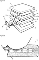
Figure 1 shows an exploded perspective view of a first embodiment of a pressure monitoring cushion; -
Figure 2 shows an exploded perspective view of a second embodiment of a pressure monitoring cushion; -
Figure 3 shows a cross-sectional view of the pressure monitoring cushion ofFigure 2 in use, where the uppermost pressure sensor is in operation; and -
Figure 4 shows a cross-sectional view of the pressure monitoring cushion ofFigure 2 in use, where the upper and lower pressure sensors are both in operation. - Referring to
Figure 1 , a first embodiment of a pressure monitoring cushion is indicated generally at 10. Thecushion 10 includes atop cushion 12 and abottom cushion 14. Another cushionedlayer 16 is provided adjacent thebottom cushion 14. The top andbottom cushions layer 16 being about half as thick as these. This corresponds to a depth of 25 mm for thecushions layer 16. The materials used to construct thecushion 10 are selected to ensure that regular washing will not cause degradation of the device or impede its functionality. - First and second pressure sensors are provided in the
cushion 10. The first and second pressure sensors are disposed in different horizontal planes in thecushion 10. In this embodiment, the pressure sensors are between thecushions cushion 10. In this embodiment, the first pressure sensor lies above the second pressure sensor in thecushion 10. The pressure sensors act as pressure switches.Fabric sheets 17 are provided between thetop cushion 12 and the cushionedlayer 16, about the first and second pressure sensors. - The first pressure sensor includes two electrical conductors (or conductive sheets) 18, 20, and a resilient electrical insulator (or insulating layer) 22 disposed between the
sheets conductive sheets layer 26 disposed between thesheets conductive sheet 20. However, other embodiments may have distinct conductive sheets for each pressure sensor. These conductive sheets (of different pressure sensors) may be separated by an insulating layer to prevent contact between them. - Each insulating
layer other cushions - Applying pressure to cushion 10 compresses the insulating
layers conductive sheets Figure 1 that the lower insulatinglayer 26 is around twice as thick as the upper insulatinglayer 22 in this embodiment. In this embodiment, the layers are 10 mm and 5 mm thick respectively. Therefore, the lower insulating layer is more difficult to compress. The actual thicknesses can be calibrated accordingly to the weight of the intended user. Overall, this gives the second pressure sensor a higher effective pressure threshold before itsconductive sheets - Each insulating
layer holes respective layer holes - The
holes 28 in the upper insulatinglayer 22 are co-aligned with theholes 30 in the lower insulatinglayer 26. In other embodiments, the holes in different layers may be anti-aligned, or have another alignment. The insulating layers 22, 26 are compressed when thecushion 10 is sat upon, but theapertures conductive sheets apertures layers - Each
conductive sheet holes conductive sheets - A
controller 34 is connected to theconductive sheets LED 36 is used to visually indicate excess pressure. Side portions of parts of thecushion 10 are cut-out to accommodate thecontroller 34 at the side of thecushion 10. - A power source or energy source (not shown) for powering the
controller 34 andLED 36 is also provided. The battery is mounted behind thecontroller 34 as viewed inFigure 2 . Together, thecontroller 34,conductive sheets LED 36 and energy source form an electrical circuit. In this embodiment, the power source is a battery. Thecontroller 34 is programmed to issue a warning signal via the output (here, LED 36) in the event that the battery charge is low. - The
controller 34 includes a processor (not shown) which controls activation of theLED 36 when a pre-set period of time (or delay period) has elapsed. In other words, thecontroller 34 delays activation of theLED 36 if theconductive sheets conductive sheets conductive sheets - In this embodiment, the pre-set period can be adjusted using a variable control (not shown), taking account of the condition of the user. The period may be set prior to using the cushion to 30 minutes, 3 hours, or any length of time between these. The variable control is a rotary switch which is adjustable using a screwdriver (or similar), preventing accidental changes to the pre-set period. It will be appreciated that the
LED 36 could be normally 'on', and delayed deactivation could be an alert instead. - The
controller 34 is also adapted to reset the delay period to its initial value if the person shifts their weight before the delay period has expired, i.e. if the patient moves and eases pressure on the skin, allowing blood to flow and reach the area which was under pressure. This is identified by monitoring whether theconductive sheets - The controller is programmed to recognise when the second pressure sensor is 'closed', i.e. the
conductive sheets conductive sheets - Referring now to
Figure 2 , a second embodiment of a pressure monitoring cushion is shown. Many of the features are the same as those of the first embodiment, and are labelled with the same reference numerals. Only features unique to the second embodiment are discussed below. - The
controller 34 includes aspeaker 38 and a processor (not shown). A representation of a clock 40 is also shown. The processor is programmed to deactivate thespeaker 38 at night. In other words, between the hours of 2200-0700, for example, the speaker will remain silent even if it would normally otherwise sound an alert. Fabric sheets are not provided between the cushions and pressure sensors in this embodiment. - The processor includes programmed verbal instructions which are played through the activated
speaker 38. In this embodiment, the controller stores instructions of approximately 2 seconds in length. The instructions are self-explanatory and tell the person atop the cushion to re-position themselves, or tell the carer the same, if the person is incapacitated for example. The instructions are recorded in different languages, so that the user can set the instruction language to one they understand. - The processor is also programmed to activate the
speaker 38 on beginning to use the cushion. Once a person has sat on the cushion, thespeaker 38 issues a tone (e.g. long beep) to indicate that it is operational. This corresponds to theconductive sheets conductive sheets - In this embodiment, the electronics of the cushion are battery-powered. The
controller 34 includes a PCB (printed circuit board, not shown) and thespeaker 38 is PCB-mounted. Thecontroller 34 activates thespeaker 38 to issue a warning sound if the battery charge is low. The warning is periodic (or intermittent), similar to that of a smoke alarm. - Referring now to
Figures 3 and4 , the pressure sensors are shown in use. InFigure 3 , a person sat on thecushion 10 has compressed the first pressure sensor and itsconductive sheets - In
Figure 4 , a person sat on thecushion 10 has compressed both the first and second pressure sensors, connecting all of theconductive sheets - In use, it is envisaged that the
cushion 10 will be used beneath a person in a chair or a bed, where the person may be a hospital patient, for example, who is confined to a sitting or lying down position. Thecushion 10 may be independent of the chair, bed or other element of furniture, or it may be integrated into (i.e. built into) the relevant item. Where the need exists to monitor multiple areas of the body that are separated by a distance greater than the size of thecushion 10, auxiliary monitoring cushions can be utilised alongside theprimary cushion 10. In general, thecushion 10 would most likely be placed beneath the head, torso (including the hips) or feet of a patient, since these general areas support the body most when lying down. - When a patient is atop the
cushion 10, the pressure exerted by the patient slowly causes the uppermostconductive sheet 18 to enter one or more of theholes 28 in the upper insulatinglayer 22. Once contact is made between theconductive sheets controller 34 begins a countdown until activation of the output (whether thespeaker 38, theLED 36, or another output). If pressure is redistributed to another area of the cushion 10 (and hence to another area of the patient's skin) by, for example, the natural movement of the patient in shifting their weight occasionally, then the delay timer will reset and start anew. This is because the shift in weight will disconnect theconductive sheets - If the pressure is not redistributed to another area of the
cushion 10 then the delay period will expire and the output device will activate. This warns the patient and/or their carer(s) that the patient has not changed position significantly over the course of the delay period and is at risk of developing a pressure ulcer, and hence attention is needed. After re-positioning, thecushion 10 continues to monitor the patient in their new position in the same manner as when monitoring their first seated position. - Other embodiments are envisaged within the scope of the claims. For example, the first pressure sensor may be divided into two distinct halves within the upper portion of the cushion. In other words, the first pressure sensor would be a dual zone pressure sensor. A patient could be positioned above one half of the first pressure sensor and, when the relevant time period had elapsed, could be turned to lie above the other half of the first pressure sensor, i.e. on the other side of the cushion. The controller would be able to distinguish between activation of either half of the first pressure sensor and reset the timing circuit accordingly.
- Further embodiments may have the cushion integrated into a car seat or a wheelchair. The electrical conductors may be composed of electrically conductive fibres as a mesh, for example. Additional pressure sensors may be provided, with greater, lesser or intermediary thickness or firmness, for example, giving a wider range of potential pressure thresholds for monitoring a patient. The controller can include a signal generator which activates after the delay period ends, sending a wireless signal to an external device. The external device receiving the signal may be a pager, a phone or a computer, for example, alerting a carer that a patient should be turned. In a further embodiment, the signal may be sent non-wirelessly.
- The cushion therefore provides an inexpensive means of detecting pressure above two different thresholds, where the first threshold corresponds to acceptable pressure for a given period of time, and the second (higher) threshold corresponds to unacceptable pressure which can only be tolerated for a shorter period of time. Re-positioning or shifting the body of a person on the cushion allows blood flow to be restored and the areas of the body that were under pressure can recover, reducing the risk of a pressure ulcer forming in those areas.
- The embodiments described above are provided by way of example only, and various changes and modifications will be apparent to persons skilled in the art without departing from the scope of the present invention as defined by the appended claims.
Claims (15)
- A pressure monitoring cushion (10) comprising first and second pressure sensors, a controller (34) configured to receive input from the pressure sensors, output means (36, 38) controlled by the controller (34), and a power source, whereineach pressure sensor includes first and second electrical conductors (18, 20, 24) and a resilient electrical insulator (22, 26) disposed between the electrical conductors (18, 20, 24);each electrical insulator (22, 26) includes one or more apertures (28, 30) through which the adjacent electrical conductors (18, 20, 24) come into contact when a threshold pressure is applied to the cushion (10);the electrical conductors (18, 20) of the first pressure sensor come into contact at a first threshold pressure, and the electrical conductors (20, 24) of the second pressure sensor come into contact at a higher second threshold pressure; andthe controller (34) triggers an output from the output means (36, 38) after a predetermined period of time has elapsed with contact between the electrical conductors (18, 20, 24) in the first and/or second pressure sensors;characterised in that the controller (34) shortens the period of time until the output means (36, 38) is triggered when the second pressure sensor detects the second threshold pressure.
- A pressure monitoring cushion (10) as claimed in claim 1, in which the output means (36, 38) issues a first output when the electrical conductors (18, 20) of the first pressure sensor are brought into contact, and the output means (36, 38) issues a different second output when the respective electrical conductors (18, 20, 24) of the first and second pressure sensors are brought into contact.
- A pressure monitoring cushion (10) as claimed in claim 1 or 2, in which at least one property of the first and/or second pressure sensors can be calibrated for a particular user.
- A pressure monitoring cushion (10) as claimed in any preceding claim, in which the resilient electrical insulator (26) of the second pressure sensor has a greater depth than the resilient electrical insulator (22) of the first pressure sensor.
- A pressure monitoring cushion (10) as claimed in any preceding claim, in which the resilient electrical insulator (26) of the second pressure sensor is more resistant to deformation than the resilient electrical insulator (22) of the first pressure sensor.
- A pressure monitoring cushion (10) as claimed in any preceding claim, in which the first and second pressure sensors are stacked within the cushion (10).
- A pressure monitoring cushion (10) as claimed in any preceding claim, in which the first and second pressure sensors have a common electrical conductor (20) between their resilient electrical insulators (22, 26).
- A pressure monitoring cushion (10) as claimed in any preceding claim, in which the controller (34) is programmed to disable or suppress the output means (36, 38) at predetermined times.
- A pressure monitoring cushion (10) as claimed in any preceding claim, in which the controller (34) is programmed to reset the period of time that has elapsed since the electrical conductors (18, 20, 24) came into contact if the electrical conductors (18, 20, 24) lose contact for an interval.
- A pressure monitoring cushion (10) as claimed in any preceding claim, in which each resilient electrical insulator (22, 26) includes foam.
- A pressure monitoring cushion (10) as claimed in any preceding claim, in which the output means includes a speaker (38), and when the period of time has elapsed, instructions are issued via the speaker (38) for a person sitting on the cushion (10) or their carer.
- A pressure monitoring cushion (10) as claimed in claim 11, in which the language of the instructions is customisable.
- A pressure monitoring cushion (10) as claimed in any preceding claim, in which the output means includes a visual indicator (36) for signalling that the period of time has elapsed.
- A pressure monitoring cushion (10) as claimed in any preceding claim, in which the output means (36, 38) includes a signal for communication with an external device.
- A pressure monitoring cushion (10) as claimed in any preceding claim, incorporated into or used with one of the following: a bed; a mattress; a seat; a chair; a wheelchair.
Applications Claiming Priority (2)
| Application Number | Priority Date | Filing Date | Title |
|---|---|---|---|
| GB1602774.0A GB2547436A (en) | 2016-02-17 | 2016-02-17 | Pressure monitoring cushion |
| PCT/GB2017/050306 WO2017141008A1 (en) | 2016-02-17 | 2017-02-08 | Pressure monitoring cushion |
Publications (3)
| Publication Number | Publication Date |
|---|---|
| EP3416526A1 EP3416526A1 (en) | 2018-12-26 |
| EP3416526B1 true EP3416526B1 (en) | 2020-01-08 |
| EP3416526B8 EP3416526B8 (en) | 2020-04-08 |
Family
ID=55697790
Family Applications (1)
| Application Number | Title | Priority Date | Filing Date |
|---|---|---|---|
| EP17705454.1A Active EP3416526B8 (en) | 2016-02-17 | 2017-02-08 | Pressure monitoring cushion |
Country Status (4)
| Country | Link |
|---|---|
| EP (1) | EP3416526B8 (en) |
| CN (1) | CN108697245B (en) |
| GB (3) | GB2547495B (en) |
| WO (1) | WO2017141008A1 (en) |
Cited By (1)
| Publication number | Priority date | Publication date | Assignee | Title |
|---|---|---|---|---|
| WO2024194224A1 (en) * | 2023-03-17 | 2024-09-26 | Baxter Medical Systems Gmbh + Co. Kg | Knitted thermal circuit system |
Families Citing this family (10)
| Publication number | Priority date | Publication date | Assignee | Title |
|---|---|---|---|---|
| WO2018167082A1 (en) * | 2017-03-13 | 2018-09-20 | Redtel, Heiko | Method and device for the time-resolved measurement of characteristic variables of the cardiac function |
| SG11202109039UA (en) * | 2019-03-11 | 2021-09-29 | Beijing Microvibration Datanet Technology Co Ltd | Signal acquisition sensor array, electronic device and mattress |
| WO2021152847A1 (en) * | 2020-01-31 | 2021-08-05 | Karlos Ishac | Posture detection system and posture detection method |
| KR102795696B1 (en) * | 2020-04-07 | 2025-04-15 | 엘지전자 주식회사 | Control method of bed |
| US11793463B2 (en) * | 2021-01-07 | 2023-10-24 | VJ Electronics Limited | Multi-zone pressure sensitive mat with two electrodes |
| GB2603171B (en) * | 2021-01-28 | 2023-11-15 | The Helping Hand Company Ledbury Ltd | A pressure monitoring cushion, system and method |
| CN113178354B (en) * | 2021-02-25 | 2022-09-30 | 宜科(天津)电子有限公司 | Pressure sensing threshold value self-adaptive pressure switch device |
| CN115576440A (en) * | 2021-06-21 | 2023-01-06 | 万魔声学股份有限公司 | an electronic device |
| TWI804098B (en) * | 2021-12-10 | 2023-06-01 | 元智大學 | Activity sensing mat, wheelchair and activity monitoring system |
| CN114847716B (en) * | 2022-06-14 | 2023-09-01 | 慕思健康睡眠股份有限公司 | Infant compression detection method, device, intelligent mattress and storage medium |
Family Cites Families (15)
| Publication number | Priority date | Publication date | Assignee | Title |
|---|---|---|---|---|
| JPH10206253A (en) * | 1997-01-21 | 1998-08-07 | Aisin Seiki Co Ltd | Pressure switch |
| US5844488A (en) * | 1997-09-23 | 1998-12-01 | Musick; Jeff L. | Bed sensor and alarm |
| US20020067273A1 (en) * | 1998-09-10 | 2002-06-06 | Senior Technologies, Inc. | Patient monitoring system |
| WO2005030008A1 (en) * | 2003-09-25 | 2005-04-07 | Eleksen Limited | Apparatus with fabric sensor |
| JP2006094903A (en) * | 2004-09-28 | 2006-04-13 | Pentax Corp | Pressure detection mat and pressure ulcer prevention system |
| SE0600562L (en) * | 2006-03-14 | 2007-09-15 | Disa Lidman | Alarm |
| CN201223179Y (en) * | 2008-06-26 | 2009-04-22 | 金飞 | Time counting cushion |
| US20100228516A1 (en) * | 2009-03-06 | 2010-09-09 | Telehealth Sensors, Llc | Electronic mattress or chair sensor for patient monitoring |
| CN202352029U (en) * | 2011-11-28 | 2012-07-25 | 无锡市恒达矿山机械有限公司 | Alarm circuit for health-care cushion |
| US9140614B2 (en) * | 2012-11-12 | 2015-09-22 | Paul Lecat | Conductive cloth sensor |
| US10398354B2 (en) * | 2013-07-12 | 2019-09-03 | Swinburne University Of Technology | Sensor array system |
| CN203720987U (en) * | 2013-11-28 | 2014-07-16 | 张俭 | Sensor pad |
| KR101547653B1 (en) * | 2013-12-13 | 2015-08-31 | 윤승환 | Posture correction system using comparison analysis about pressure distribution chart |
| CN204105482U (en) * | 2014-10-10 | 2015-01-21 | 北京京东世纪贸易有限公司 | An anti-sedentary reminder device and a mat with a built-in anti-sedentary reminder device |
| CN204596070U (en) * | 2015-05-04 | 2015-08-26 | 侯志广 | Intelligent-induction pad |
-
2016
- 2016-02-17 GB GB1612632.8A patent/GB2547495B/en active Active
- 2016-02-17 GB GB1602774.0A patent/GB2547436A/en not_active Withdrawn
- 2016-02-17 GB GB1612633.6A patent/GB2547496A/en not_active Withdrawn
-
2017
- 2017-02-08 WO PCT/GB2017/050306 patent/WO2017141008A1/en not_active Ceased
- 2017-02-08 CN CN201780011395.7A patent/CN108697245B/en active Active
- 2017-02-08 EP EP17705454.1A patent/EP3416526B8/en active Active
Non-Patent Citations (1)
| Title |
|---|
| None * |
Cited By (1)
| Publication number | Priority date | Publication date | Assignee | Title |
|---|---|---|---|---|
| WO2024194224A1 (en) * | 2023-03-17 | 2024-09-26 | Baxter Medical Systems Gmbh + Co. Kg | Knitted thermal circuit system |
Also Published As
| Publication number | Publication date |
|---|---|
| CN108697245B (en) | 2020-06-23 |
| WO2017141008A1 (en) | 2017-08-24 |
| EP3416526B8 (en) | 2020-04-08 |
| GB201612632D0 (en) | 2016-09-07 |
| GB2547495A (en) | 2017-08-23 |
| GB201612633D0 (en) | 2016-09-07 |
| GB201602774D0 (en) | 2016-03-30 |
| GB2547496A (en) | 2017-08-23 |
| CN108697245A (en) | 2018-10-23 |
| GB2547495B (en) | 2021-09-22 |
| GB2547436A (en) | 2017-08-23 |
| EP3416526A1 (en) | 2018-12-26 |
Similar Documents
| Publication | Publication Date | Title |
|---|---|---|
| EP3416526A1 (en) | Pressure monitoring cushion | |
| EP3416603B1 (en) | Support evaluation device | |
| US5519380A (en) | Personal monitoring system and method | |
| US7656299B2 (en) | Bed exit and patient detection system | |
| US6917293B2 (en) | Integral, flexible, electronic patient sensing and monitoring system | |
| US8558702B2 (en) | Apparatus and method for preventing pressure injuries and circulatory problems in sedentary patients | |
| WO2018130824A1 (en) | Cushion | |
| WO2000000081A1 (en) | Pressure relief reminder and compliance system | |
| US20150128354A1 (en) | Methods, circuits, apparatuses and assemblies for providing a mattress or body portion support cushion with a sensor layer | |
| WO2017032393A1 (en) | System and process for controlling the risks of appearance of pressure ulcers | |
| DK2781209T3 (en) | Mattress | |
| US20240307219A1 (en) | Knitted thermal circuit system | |
| US20220257174A1 (en) | An electrical stimulation system | |
| EP4284233B1 (en) | A pressure monitoring device, system and method | |
| CN204890415U (en) | Medical mattress | |
| Rocha et al. | System providing discomfort monitoring for people in wheelchairs | |
| CN101248329A (en) | proximity sensor | |
| Rush | Sensation augmentation to relieve pressure sore formation in wheelchair users | |
| CN207133948U (en) | A kind of warning device for medical bed mattress | |
| WO1993012834A1 (en) | Pad for preventing bed sore | |
| JP6055579B2 (en) | Biological sensor | |
| Lowthian | Acute patient care: pressure areas |
Legal Events
| Date | Code | Title | Description |
|---|---|---|---|
| STAA | Information on the status of an ep patent application or granted ep patent |
Free format text: STATUS: UNKNOWN |
|
| STAA | Information on the status of an ep patent application or granted ep patent |
Free format text: STATUS: THE INTERNATIONAL PUBLICATION HAS BEEN MADE |
|
| PUAI | Public reference made under article 153(3) epc to a published international application that has entered the european phase |
Free format text: ORIGINAL CODE: 0009012 |
|
| STAA | Information on the status of an ep patent application or granted ep patent |
Free format text: STATUS: REQUEST FOR EXAMINATION WAS MADE |
|
| 17P | Request for examination filed |
Effective date: 20180814 |
|
| AK | Designated contracting states |
Kind code of ref document: A1 Designated state(s): AL AT BE BG CH CY CZ DE DK EE ES FI FR GB GR HR HU IE IS IT LI LT LU LV MC MK MT NL NO PL PT RO RS SE SI SK SM TR |
|
| AX | Request for extension of the european patent |
Extension state: BA ME |
|
| DAV | Request for validation of the european patent (deleted) | ||
| DAX | Request for extension of the european patent (deleted) | ||
| GRAP | Despatch of communication of intention to grant a patent |
Free format text: ORIGINAL CODE: EPIDOSNIGR1 |
|
| STAA | Information on the status of an ep patent application or granted ep patent |
Free format text: STATUS: GRANT OF PATENT IS INTENDED |
|
| INTG | Intention to grant announced |
Effective date: 20191025 |
|
| GRAS | Grant fee paid |
Free format text: ORIGINAL CODE: EPIDOSNIGR3 |
|
| GRAA | (expected) grant |
Free format text: ORIGINAL CODE: 0009210 |
|
| STAA | Information on the status of an ep patent application or granted ep patent |
Free format text: STATUS: THE PATENT HAS BEEN GRANTED |
|
| AK | Designated contracting states |
Kind code of ref document: B1 Designated state(s): AL AT BE BG CH CY CZ DE DK EE ES FI FR GB GR HR HU IE IS IT LI LT LU LV MC MK MT NL NO PL PT RO RS SE SI SK SM TR |
|
| REG | Reference to a national code |
Ref country code: GB Ref legal event code: FG4D |
|
| REG | Reference to a national code |
Ref country code: CH Ref legal event code: EP |
|
| REG | Reference to a national code |
Ref country code: DE Ref legal event code: R096 Ref document number: 602017010679 Country of ref document: DE |
|
| REG | Reference to a national code |
Ref country code: IE Ref legal event code: FG4D |
|
| REG | Reference to a national code |
Ref country code: AT Ref legal event code: REF Ref document number: 1221604 Country of ref document: AT Kind code of ref document: T Effective date: 20200215 |
|
| GRAT | Correction requested after decision to grant or after decision to maintain patent in amended form |
Free format text: ORIGINAL CODE: EPIDOSNCDEC |
|
| REG | Reference to a national code |
Ref country code: CH Ref legal event code: PK Free format text: BERICHTIGUNG B8 |
|
| REG | Reference to a national code |
Ref country code: NL Ref legal event code: FP |
|
| RAP2 | Party data changed (patent owner data changed or rights of a patent transferred) |
Owner name: THE HELPING HAND COMPANY (LEDBURY) LIMITED |
|
| REG | Reference to a national code |
Ref country code: LT Ref legal event code: MG4D |
|
| PG25 | Lapsed in a contracting state [announced via postgrant information from national office to epo] |
Ref country code: PT Free format text: LAPSE BECAUSE OF FAILURE TO SUBMIT A TRANSLATION OF THE DESCRIPTION OR TO PAY THE FEE WITHIN THE PRESCRIBED TIME-LIMIT Effective date: 20200531 Ref country code: LT Free format text: LAPSE BECAUSE OF FAILURE TO SUBMIT A TRANSLATION OF THE DESCRIPTION OR TO PAY THE FEE WITHIN THE PRESCRIBED TIME-LIMIT Effective date: 20200108 Ref country code: NO Free format text: LAPSE BECAUSE OF FAILURE TO SUBMIT A TRANSLATION OF THE DESCRIPTION OR TO PAY THE FEE WITHIN THE PRESCRIBED TIME-LIMIT Effective date: 20200408 Ref country code: RS Free format text: LAPSE BECAUSE OF FAILURE TO SUBMIT A TRANSLATION OF THE DESCRIPTION OR TO PAY THE FEE WITHIN THE PRESCRIBED TIME-LIMIT Effective date: 20200108 Ref country code: FI Free format text: LAPSE BECAUSE OF FAILURE TO SUBMIT A TRANSLATION OF THE DESCRIPTION OR TO PAY THE FEE WITHIN THE PRESCRIBED TIME-LIMIT Effective date: 20200108 |
|
| PG25 | Lapsed in a contracting state [announced via postgrant information from national office to epo] |
Ref country code: LV Free format text: LAPSE BECAUSE OF FAILURE TO SUBMIT A TRANSLATION OF THE DESCRIPTION OR TO PAY THE FEE WITHIN THE PRESCRIBED TIME-LIMIT Effective date: 20200108 Ref country code: HR Free format text: LAPSE BECAUSE OF FAILURE TO SUBMIT A TRANSLATION OF THE DESCRIPTION OR TO PAY THE FEE WITHIN THE PRESCRIBED TIME-LIMIT Effective date: 20200108 Ref country code: BG Free format text: LAPSE BECAUSE OF FAILURE TO SUBMIT A TRANSLATION OF THE DESCRIPTION OR TO PAY THE FEE WITHIN THE PRESCRIBED TIME-LIMIT Effective date: 20200408 Ref country code: GR Free format text: LAPSE BECAUSE OF FAILURE TO SUBMIT A TRANSLATION OF THE DESCRIPTION OR TO PAY THE FEE WITHIN THE PRESCRIBED TIME-LIMIT Effective date: 20200409 Ref country code: SE Free format text: LAPSE BECAUSE OF FAILURE TO SUBMIT A TRANSLATION OF THE DESCRIPTION OR TO PAY THE FEE WITHIN THE PRESCRIBED TIME-LIMIT Effective date: 20200108 Ref country code: IS Free format text: LAPSE BECAUSE OF FAILURE TO SUBMIT A TRANSLATION OF THE DESCRIPTION OR TO PAY THE FEE WITHIN THE PRESCRIBED TIME-LIMIT Effective date: 20200508 |
|
| REG | Reference to a national code |
Ref country code: CH Ref legal event code: PL |
|
| REG | Reference to a national code |
Ref country code: DE Ref legal event code: R097 Ref document number: 602017010679 Country of ref document: DE |
|
| REG | Reference to a national code |
Ref country code: BE Ref legal event code: MM Effective date: 20200229 |
|
| PG25 | Lapsed in a contracting state [announced via postgrant information from national office to epo] |
Ref country code: SK Free format text: LAPSE BECAUSE OF FAILURE TO SUBMIT A TRANSLATION OF THE DESCRIPTION OR TO PAY THE FEE WITHIN THE PRESCRIBED TIME-LIMIT Effective date: 20200108 Ref country code: CZ Free format text: LAPSE BECAUSE OF FAILURE TO SUBMIT A TRANSLATION OF THE DESCRIPTION OR TO PAY THE FEE WITHIN THE PRESCRIBED TIME-LIMIT Effective date: 20200108 Ref country code: DK Free format text: LAPSE BECAUSE OF FAILURE TO SUBMIT A TRANSLATION OF THE DESCRIPTION OR TO PAY THE FEE WITHIN THE PRESCRIBED TIME-LIMIT Effective date: 20200108 Ref country code: RO Free format text: LAPSE BECAUSE OF FAILURE TO SUBMIT A TRANSLATION OF THE DESCRIPTION OR TO PAY THE FEE WITHIN THE PRESCRIBED TIME-LIMIT Effective date: 20200108 Ref country code: EE Free format text: LAPSE BECAUSE OF FAILURE TO SUBMIT A TRANSLATION OF THE DESCRIPTION OR TO PAY THE FEE WITHIN THE PRESCRIBED TIME-LIMIT Effective date: 20200108 Ref country code: SM Free format text: LAPSE BECAUSE OF FAILURE TO SUBMIT A TRANSLATION OF THE DESCRIPTION OR TO PAY THE FEE WITHIN THE PRESCRIBED TIME-LIMIT Effective date: 20200108 Ref country code: MC Free format text: LAPSE BECAUSE OF FAILURE TO SUBMIT A TRANSLATION OF THE DESCRIPTION OR TO PAY THE FEE WITHIN THE PRESCRIBED TIME-LIMIT Effective date: 20200108 Ref country code: ES Free format text: LAPSE BECAUSE OF FAILURE TO SUBMIT A TRANSLATION OF THE DESCRIPTION OR TO PAY THE FEE WITHIN THE PRESCRIBED TIME-LIMIT Effective date: 20200108 Ref country code: LU Free format text: LAPSE BECAUSE OF NON-PAYMENT OF DUE FEES Effective date: 20200208 |
|
| PLBE | No opposition filed within time limit |
Free format text: ORIGINAL CODE: 0009261 |
|
| STAA | Information on the status of an ep patent application or granted ep patent |
Free format text: STATUS: NO OPPOSITION FILED WITHIN TIME LIMIT |
|
| REG | Reference to a national code |
Ref country code: AT Ref legal event code: MK05 Ref document number: 1221604 Country of ref document: AT Kind code of ref document: T Effective date: 20200108 |
|
| PG25 | Lapsed in a contracting state [announced via postgrant information from national office to epo] |
Ref country code: LI Free format text: LAPSE BECAUSE OF NON-PAYMENT OF DUE FEES Effective date: 20200229 Ref country code: CH Free format text: LAPSE BECAUSE OF NON-PAYMENT OF DUE FEES Effective date: 20200229 |
|
| 26N | No opposition filed |
Effective date: 20201009 |
|
| PG25 | Lapsed in a contracting state [announced via postgrant information from national office to epo] |
Ref country code: AT Free format text: LAPSE BECAUSE OF FAILURE TO SUBMIT A TRANSLATION OF THE DESCRIPTION OR TO PAY THE FEE WITHIN THE PRESCRIBED TIME-LIMIT Effective date: 20200108 Ref country code: IT Free format text: LAPSE BECAUSE OF FAILURE TO SUBMIT A TRANSLATION OF THE DESCRIPTION OR TO PAY THE FEE WITHIN THE PRESCRIBED TIME-LIMIT Effective date: 20200108 Ref country code: IE Free format text: LAPSE BECAUSE OF NON-PAYMENT OF DUE FEES Effective date: 20200208 |
|
| PG25 | Lapsed in a contracting state [announced via postgrant information from national office to epo] |
Ref country code: PL Free format text: LAPSE BECAUSE OF FAILURE TO SUBMIT A TRANSLATION OF THE DESCRIPTION OR TO PAY THE FEE WITHIN THE PRESCRIBED TIME-LIMIT Effective date: 20200108 Ref country code: BE Free format text: LAPSE BECAUSE OF NON-PAYMENT OF DUE FEES Effective date: 20200229 Ref country code: SI Free format text: LAPSE BECAUSE OF FAILURE TO SUBMIT A TRANSLATION OF THE DESCRIPTION OR TO PAY THE FEE WITHIN THE PRESCRIBED TIME-LIMIT Effective date: 20200108 |
|
| PG25 | Lapsed in a contracting state [announced via postgrant information from national office to epo] |
Ref country code: TR Free format text: LAPSE BECAUSE OF FAILURE TO SUBMIT A TRANSLATION OF THE DESCRIPTION OR TO PAY THE FEE WITHIN THE PRESCRIBED TIME-LIMIT Effective date: 20200108 Ref country code: MT Free format text: LAPSE BECAUSE OF FAILURE TO SUBMIT A TRANSLATION OF THE DESCRIPTION OR TO PAY THE FEE WITHIN THE PRESCRIBED TIME-LIMIT Effective date: 20200108 Ref country code: CY Free format text: LAPSE BECAUSE OF FAILURE TO SUBMIT A TRANSLATION OF THE DESCRIPTION OR TO PAY THE FEE WITHIN THE PRESCRIBED TIME-LIMIT Effective date: 20200108 |
|
| PG25 | Lapsed in a contracting state [announced via postgrant information from national office to epo] |
Ref country code: MK Free format text: LAPSE BECAUSE OF FAILURE TO SUBMIT A TRANSLATION OF THE DESCRIPTION OR TO PAY THE FEE WITHIN THE PRESCRIBED TIME-LIMIT Effective date: 20200108 Ref country code: AL Free format text: LAPSE BECAUSE OF FAILURE TO SUBMIT A TRANSLATION OF THE DESCRIPTION OR TO PAY THE FEE WITHIN THE PRESCRIBED TIME-LIMIT Effective date: 20200108 |
|
| PGFP | Annual fee paid to national office [announced via postgrant information from national office to epo] |
Ref country code: NL Payment date: 20260112 Year of fee payment: 10 |
|
| PGFP | Annual fee paid to national office [announced via postgrant information from national office to epo] |
Ref country code: GB Payment date: 20260108 Year of fee payment: 10 |
|
| PGFP | Annual fee paid to national office [announced via postgrant information from national office to epo] |
Ref country code: DE Payment date: 20260112 Year of fee payment: 10 |
|
| PGFP | Annual fee paid to national office [announced via postgrant information from national office to epo] |
Ref country code: FR Payment date: 20260112 Year of fee payment: 10 |