EP3416377A1 - Image display device and method for displaying image - Google Patents
Image display device and method for displaying image Download PDFInfo
- Publication number
- EP3416377A1 EP3416377A1 EP17750022.0A EP17750022A EP3416377A1 EP 3416377 A1 EP3416377 A1 EP 3416377A1 EP 17750022 A EP17750022 A EP 17750022A EP 3416377 A1 EP3416377 A1 EP 3416377A1
- Authority
- EP
- European Patent Office
- Prior art keywords
- image
- information
- driver
- display
- hud
- Prior art date
- Legal status (The legal status is an assumption and is not a legal conclusion. Google has not performed a legal analysis and makes no representation as to the accuracy of the status listed.)
- Granted
Links
Images


Classifications
-
- G—PHYSICS
- G01—MEASURING; TESTING
- G01C—MEASURING DISTANCES, LEVELS OR BEARINGS; SURVEYING; NAVIGATION; GYROSCOPIC INSTRUMENTS; PHOTOGRAMMETRY OR VIDEOGRAMMETRY
- G01C21/00—Navigation; Navigational instruments not provided for in groups G01C1/00 - G01C19/00
- G01C21/26—Navigation; Navigational instruments not provided for in groups G01C1/00 - G01C19/00 specially adapted for navigation in a road network
- G01C21/34—Route searching; Route guidance
- G01C21/36—Input/output arrangements for on-board computers
- G01C21/3626—Details of the output of route guidance instructions
- G01C21/365—Guidance using head up displays or projectors, e.g. virtual vehicles or arrows projected on the windscreen or on the road itself
-
- G—PHYSICS
- G02—OPTICS
- G02B—OPTICAL ELEMENTS, SYSTEMS OR APPARATUS
- G02B27/00—Optical systems or apparatus not provided for by any of the groups G02B1/00 - G02B26/00, G02B30/00
- G02B27/01—Head-up displays
- G02B27/0101—Head-up displays characterised by optical features
-
- B—PERFORMING OPERATIONS; TRANSPORTING
- B60—VEHICLES IN GENERAL
- B60K—ARRANGEMENT OR MOUNTING OF PROPULSION UNITS OR OF TRANSMISSIONS IN VEHICLES; ARRANGEMENT OR MOUNTING OF PLURAL DIVERSE PRIME-MOVERS IN VEHICLES; AUXILIARY DRIVES FOR VEHICLES; INSTRUMENTATION OR DASHBOARDS FOR VEHICLES; ARRANGEMENTS IN CONNECTION WITH COOLING, AIR INTAKE, GAS EXHAUST OR FUEL SUPPLY OF PROPULSION UNITS IN VEHICLES
- B60K35/00—Instruments specially adapted for vehicles; Arrangement of instruments in or on vehicles
- B60K35/10—Input arrangements, i.e. from user to vehicle, associated with vehicle functions or specially adapted therefor
-
- B—PERFORMING OPERATIONS; TRANSPORTING
- B60—VEHICLES IN GENERAL
- B60K—ARRANGEMENT OR MOUNTING OF PROPULSION UNITS OR OF TRANSMISSIONS IN VEHICLES; ARRANGEMENT OR MOUNTING OF PLURAL DIVERSE PRIME-MOVERS IN VEHICLES; AUXILIARY DRIVES FOR VEHICLES; INSTRUMENTATION OR DASHBOARDS FOR VEHICLES; ARRANGEMENTS IN CONNECTION WITH COOLING, AIR INTAKE, GAS EXHAUST OR FUEL SUPPLY OF PROPULSION UNITS IN VEHICLES
- B60K35/00—Instruments specially adapted for vehicles; Arrangement of instruments in or on vehicles
- B60K35/20—Output arrangements, i.e. from vehicle to user, associated with vehicle functions or specially adapted therefor
- B60K35/21—Output arrangements, i.e. from vehicle to user, associated with vehicle functions or specially adapted therefor using visual output, e.g. blinking lights or matrix displays
- B60K35/23—Head-up displays [HUD]
- B60K35/233—Head-up displays [HUD] controlling the size or position in display areas of virtual images depending on the condition of the vehicle or the driver
-
- B—PERFORMING OPERATIONS; TRANSPORTING
- B60—VEHICLES IN GENERAL
- B60K—ARRANGEMENT OR MOUNTING OF PROPULSION UNITS OR OF TRANSMISSIONS IN VEHICLES; ARRANGEMENT OR MOUNTING OF PLURAL DIVERSE PRIME-MOVERS IN VEHICLES; AUXILIARY DRIVES FOR VEHICLES; INSTRUMENTATION OR DASHBOARDS FOR VEHICLES; ARRANGEMENTS IN CONNECTION WITH COOLING, AIR INTAKE, GAS EXHAUST OR FUEL SUPPLY OF PROPULSION UNITS IN VEHICLES
- B60K35/00—Instruments specially adapted for vehicles; Arrangement of instruments in or on vehicles
- B60K35/20—Output arrangements, i.e. from vehicle to user, associated with vehicle functions or specially adapted therefor
- B60K35/21—Output arrangements, i.e. from vehicle to user, associated with vehicle functions or specially adapted therefor using visual output, e.g. blinking lights or matrix displays
- B60K35/23—Head-up displays [HUD]
- B60K35/235—Head-up displays [HUD] with means for detecting the driver's gaze direction or eye points
-
- B—PERFORMING OPERATIONS; TRANSPORTING
- B60—VEHICLES IN GENERAL
- B60R—VEHICLES, VEHICLE FITTINGS, OR VEHICLE PARTS, NOT OTHERWISE PROVIDED FOR
- B60R11/00—Arrangements for holding or mounting articles, not otherwise provided for
- B60R11/02—Arrangements for holding or mounting articles, not otherwise provided for for radio sets, television sets, telephones, or the like; Arrangement of controls thereof
-
- B—PERFORMING OPERATIONS; TRANSPORTING
- B60—VEHICLES IN GENERAL
- B60R—VEHICLES, VEHICLE FITTINGS, OR VEHICLE PARTS, NOT OTHERWISE PROVIDED FOR
- B60R11/00—Arrangements for holding or mounting articles, not otherwise provided for
- B60R11/04—Mounting of cameras operative during drive; Arrangement of controls thereof relative to the vehicle
-
- G—PHYSICS
- G06—COMPUTING OR CALCULATING; COUNTING
- G06F—ELECTRIC DIGITAL DATA PROCESSING
- G06F3/00—Input arrangements for transferring data to be processed into a form capable of being handled by the computer; Output arrangements for transferring data from processing unit to output unit, e.g. interface arrangements
- G06F3/01—Input arrangements or combined input and output arrangements for interaction between user and computer
- G06F3/011—Arrangements for interaction with the human body, e.g. for user immersion in virtual reality
- G06F3/012—Head tracking input arrangements
-
- G—PHYSICS
- G06—COMPUTING OR CALCULATING; COUNTING
- G06V—IMAGE OR VIDEO RECOGNITION OR UNDERSTANDING
- G06V40/00—Recognition of biometric, human-related or animal-related patterns in image or video data
- G06V40/10—Human or animal bodies, e.g. vehicle occupants or pedestrians; Body parts, e.g. hands
- G06V40/16—Human faces, e.g. facial parts, sketches or expressions
-
- G—PHYSICS
- G09—EDUCATION; CRYPTOGRAPHY; DISPLAY; ADVERTISING; SEALS
- G09G—ARRANGEMENTS OR CIRCUITS FOR CONTROL OF INDICATING DEVICES USING STATIC MEANS TO PRESENT VARIABLE INFORMATION
- G09G5/00—Control arrangements or circuits for visual indicators common to cathode-ray tube indicators and other visual indicators
-
- H—ELECTRICITY
- H04—ELECTRIC COMMUNICATION TECHNIQUE
- H04N—PICTORIAL COMMUNICATION, e.g. TELEVISION
- H04N7/00—Television systems
- H04N7/18—Closed-circuit television [CCTV] systems, i.e. systems in which the video signal is not broadcast
-
- B—PERFORMING OPERATIONS; TRANSPORTING
- B60—VEHICLES IN GENERAL
- B60K—ARRANGEMENT OR MOUNTING OF PROPULSION UNITS OR OF TRANSMISSIONS IN VEHICLES; ARRANGEMENT OR MOUNTING OF PLURAL DIVERSE PRIME-MOVERS IN VEHICLES; AUXILIARY DRIVES FOR VEHICLES; INSTRUMENTATION OR DASHBOARDS FOR VEHICLES; ARRANGEMENTS IN CONNECTION WITH COOLING, AIR INTAKE, GAS EXHAUST OR FUEL SUPPLY OF PROPULSION UNITS IN VEHICLES
- B60K2360/00—Indexing scheme associated with groups B60K35/00 or B60K37/00 relating to details of instruments or dashboards
- B60K2360/20—Optical features of instruments
- B60K2360/33—Illumination features
- B60K2360/334—Projection means
-
- G—PHYSICS
- G02—OPTICS
- G02B—OPTICAL ELEMENTS, SYSTEMS OR APPARATUS
- G02B27/00—Optical systems or apparatus not provided for by any of the groups G02B1/00 - G02B26/00, G02B30/00
- G02B27/01—Head-up displays
- G02B27/0101—Head-up displays characterised by optical features
- G02B2027/0138—Head-up displays characterised by optical features comprising image capture systems, e.g. camera
-
- G—PHYSICS
- G02—OPTICS
- G02B—OPTICAL ELEMENTS, SYSTEMS OR APPARATUS
- G02B27/00—Optical systems or apparatus not provided for by any of the groups G02B1/00 - G02B26/00, G02B30/00
- G02B27/01—Head-up displays
- G02B27/0101—Head-up displays characterised by optical features
- G02B2027/014—Head-up displays characterised by optical features comprising information/image processing systems
Definitions
- the present invention relates to an image display apparatus and an image display method.
- a head-up display (hereinafter, referred to as a HUD) to be installed in a vehicle has been progressing.
- Expectations for a HUD have increased in the market, as an apparatus for a vehicle's driver to be able to recognize an alarm and information with a small amount of line-of-sight movement.
- ADAS Advanced Driving Assistance System
- a vehicle has been able to acquire various types of traveling environment information and vehicle occupant information.
- a HUD to be installed in a vehicle has also drawn attention as an "outlet of ADAS" that transmits the various types of traveling environment information and vehicle occupant information to the driver.
- a HUD to be installed in a vehicle displays an image as a virtual image ahead of the driver's visual point position by several meters.
- the HUD to be installed in the vehicle is capable of displaying the image as if the image were located in a real space in front of the vehicle.
- Such technology with which an image appears as if the image were present in a real space is called AR (Augmented Reality), and it is considered that the technology enables various types of information to be intuitionally displayed to the driver.
- An object of the disclosure is to improve a viewer's visibility for a case where, if an image displayed by an image display apparatus and an object at the same position as or near a position of the image were viewed from a position of the viewer's visual point, the image would overlap with the object.
- An image display apparatus includes a display section configured to display an image; a detecting section configured to detect an object at the same position as or near a position of the image; and a control section configured to control the image in response to determining overlap of the object with the image when viewed from a position of a visual point of a viewer viewing the image.
- An embodiment according to the present invention improves a viewer's visibility for a case where, for example, there is an object such as another vehicle in front of a vehicle, and, if an image displayed by a HUD 200 and the object are viewed from a viewer, the image is superposed on the object.
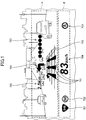
- FIG. 1 is a forward view illustrating one example of a virtual image displayed by an automotive HUD 200 (hereinafter, simply referred to as a HUD 200) according to an embodiment of the present invention in a state where the virtual image is superposed on a landscape, which a driver can see through a windshield 302, in front of a vehicle 301.
- FIG. 2 is a partially-cutaway schematic side view schematically illustrating an inner arrangement of an automobile in which the HUD 200 according to the embodiment is installed.
- FIG. 3 is a block diagram schematically illustrating a configuration example of an optical system of the HUD 200 of FIG. 2 .
- the HUD 200 is one example of an image display apparatus.
- the HUD 200 is installed, for example, inside a dashboard of the vehicle 301 that is a traveling body as a mobile body.
- Projected light L that is image light emitted by the HUD 200 inside the dashboard is reflected by the windshield 302 that is a light transmissive member, and the driver 300 who is a viewer is irradiated with the projected light L.
- the driver 300 can see a route navigation image or the like described later as the virtual image G.
- a combiner is installed as a light transmissive member on the inner wall of the windshield 302, and the projected light L reflected by the combiner allows the driver 300 to see the virtual image G.
- the forward shooting camera 110 takes a picture of a forward view.
- the forward view a picture of which is taken by the forward shooting camera 110 includes display information displayed by the HUD 200 onto the windshield 302 and a background of the display information. That is, the forward shooting camera 110 takes a picture of the display information displayed by the HUD 200 onto the windshield 302 and a picture of the background through the windshield 302.
- the background a picture of which is taken by the forward shooting camera 110 through the windshield 302 includes an environment in front of the vehicle 301 (i.e., a preceding vehicle, a road surface, and so forth).
- the driver camera 150 takes a picture of the driver 300 for detecting the visual point position of the driver 300.
- the optical system 230 of the HUD 200 and so forth are designed in such a manner that the distance from the driver 300 to the virtual image G is greater than or equal to 5 m.
- a distance from a driver to a virtual image is approximately 2 m.
- a driver carefully watches a forward infinite point of the vehicle, or carefully watches a preceding vehicle at several tens of meters.
- the focal length varies greatly. As a result, the driver greatly moves the lenses of the eyes.
- a focus adjustment time taken until the virtual image is focused increases, a time is taken for the driver to recognize the contents of the virtual image, and the driver's eyeballs may become easily tired. Further, it is not easy for the driver to notice the contents of the virtual image, and it may be difficult to appropriately provide information to the driver with the virtual image.
- the distance to the virtual image G is greater than or equal to 5 m in the present embodiment
- an amount by which the driver 300 moves the lenses of the eyes is reduced from the amount of the conventional case, and the focus adjustment time taken until the virtual image G is focused is reduced so that the driver can rapidly recognize the contents of the virtual image G.
- the driver 300 can easily notice the contents of the virtual image G, and it is possible to appropriately provide information to the driver 300 with the virtual image G easily.
- the driver 300 can focus on the virtual image G almost without performing convergence movement of the eyeballs.
- the optical system 230 of the HUD 200 illustrated in FIG. 3 includes red, green, and blue laser light sources 201R, 201G, and 201B; collimator lenses 202, 203, and 204 for the respective laser light sources; and two dichroic mirrors 205 and 206.
- the optical system 230 further includes a light intensity adjustment section 207, an optical scanning apparatus 208 as an optical scanning section, a free-curved mirror 209, a micro-lens array 210 as a light divergence member, and a projection mirror 211 as a light reflecting member.
- the laser light sources 201R, 201G, and 201B, the collimator lenses 202, 203, and 204, and the dichroic mirrors 205 and 206 are integrated with an optical housing.
- LDs semiconductor laser devices
- the wavelength of the beam emitted by the red laser light source 201R is, for example, 640 nm
- the wavelength of the beam emitted by the green laser light source 201G is, for example, 530 nm
- the wavelength of the beam emitted by the blue laser light source 201B is, for example, 445 nm.
- an intermediate image formed on the micro-lens array 210 is projected onto the windshield 302 of the vehicle 301.
- the driver 300 is able to see a magnified image of the intermediate image as the virtual image G.
- the laser light of the corresponding color emitted from each of the laser light sources 201R, 201G, and 201B is transformed into approximately parallel light by the corresponding one of the collimator lenses 202, 203, and 204, and thereafter, is combined with the other two colors of laser light by the two dichroic mirrors 205 and 206.
- the light intensity adjustment section 207 adjusts the light intensity of the combined laser light, and thereafter the laser light is deflected by the mirror of the optical scanning apparatus 208 to scan the free-curved mirror 209 two-dimensionally.
- the scanning light L' that scans the free-curved mirror 209 two-dimensionally as a result of being deflected by the optical scanning apparatus 208 is reflected by the free-curved mirror 209 so that distortion is corrected, and thereafter is concentrated onto the micro-lens array 210 and renders the intermediate image G' on the micro-lens array 210.
- the micro-lens array 210 is used as the light divergence member to divergently emit the beams corresponding to the respective pixels of the intermediate image G' (the respective points of the intermediate image).
- the light divergence member it is possible to use another light divergence member.
- the laser scanning type as in the present embodiment is desirable for displaying the large virtual image G with high brightness.
- the HUD 200 performs a display control process to gradually increase the brightness of the alarm image from among various images included in the virtual image G.
- the laser scanning type is desirable. If a liquid crystal display (LCD) or a fluorescent display tube (VFD) were used, also the brightness of images other than the alarm image included in the virtual image displayed by the HUD 200 might be increased together.
- the optical scanning apparatus 208 inclines the mirror in the main-scanning direction and in the sub-scanning direction with the use of a known actuator driving system such as a MEMS (Micro Electronic Mechanical Systems), to deflect the laser light that is incident on the mirror to two-dimensionally scan (raster scan) the free-curved mirror 209. Controlling the driving of the mirror is in synchronization with the light emission timing of the laser light sources 201R, 201G, and 201B.
- a known actuator driving system such as a MEMS (Micro Electronic Mechanical Systems)
- MEMS Micro Electronic Mechanical Systems
- Controlling the driving of the mirror is in synchronization with the light emission timing of the laser light sources 201R, 201G, and 201B.
- the optical scanning apparatus 208 is not limited to having the above-described configuration.
- an optical scanning apparatus using a mirror system including two mirrors that are oscillated or rotated about two mutually orthogonal axes may be used instead.
- FIG. 4 is a block diagram illustrating a configuration example of the control system 250 of the HUD 200 of FIG. 2 .
- the control system 250 of the HUD 200 includes a FPGA (Field Programmable Gate Array) 251, a CPU (Central Processing Unit) 252, a ROM (Read-Only Memory) 253, a RAM (Random Access Memory) 254, an interface (hereinafter, referred to as I/F) 255, a bus line 256, a LD driver 257, and a MEMS controller 258.
- FPGA Field Programmable Gate Array
- CPU Central Processing Unit
- ROM Read-Only Memory
- RAM Random Access Memory
- the FPGA 251 uses the LD driver 257 to control the laser light sources 201R, 201G, and 201B of the light source unit 220, and uses the MEMS controller 258 to control the MEMS 208a of the optical scanning apparatus 208.
- the CPU 252 implements various functions of the HUD 200.
- the ROM 253 stores various programs such as an image processing program for the CPU 252 to implement the various functions of the HUD 200.
- the RAM 254 is used as a work area of the CPU 252.
- the I/F 255 is an interface for communication with an external controller or the like, and is connected with, for example, a vehicle navigation apparatus 400, a various-sensor apparatus 500, and so forth via a CAN (Controller Area Network) of the vehicle 301.
- CAN Controller Area Network
- the forward shooting camera 110 takes a picture of a forward view of the vehicle 301, i.e., the forward shooting camera 110 takes a picture of the display information displayed by the HUD 200 on the windshield 302, and takes a picture of the background of the display information through the windshield 302.
- the driver camera 150 is connected to the I/F 255.
- the driver camera 150 is used to detect the visual point position of the driver 300.
- the control system 250 performs image processing on the pictures of the display information and the background to convert the pictures into a picture that would be obtained if the display information and the background were viewed from the visual point position of the driver 300 on the basis of the detected visual point position of the driver 300.
- the control system 250 detects the visual point position of the driver 300 by, for example, performing image analysis on the picture of the head of the driver 300 taken by the driver camera 150.
- FIG. 5 is a block diagram illustrating a general arrangement of peripheral apparatuses of the HUD 200 of FIG. 2 .
- the HUD 200 mainly includes the optical system 230 that is one example of a display section and the control system 250 that is one example of a control section.
- the vehicle navigation apparatus 400 As the vehicle navigation apparatus 400 according to the present embodiment, a known vehicle navigation apparatus installed in an automobile or the like can be extensively used.
- the vehicle navigation apparatus 400 outputs information to generate a route navigation image to be displayed as the virtual image G; the information is input to the control system 250.
- the route navigation image includes, for example, as illustrated in FIG. 1 , images that indicate the number of lanes (travelling lanes) of the road on which the vehicle 301 is traveling; the distance to the position at which the next course change (turning right, turning left, entering a branch route, or the like) will be performed; the direction in which the course change will be performed, and so forth. These types of information are input to the control system 250 from the vehicle navigation apparatus 400.
- the HUD 200 displays as the virtual image G the route navigation images such as a travelling lane image 711, a vehicular gap image 712, a course instruction image 721, a remaining distance image 722, an intersection (or the like) name image 723, and so forth in an upper image display area A.
- the route navigation images such as a travelling lane image 711, a vehicular gap image 712, a course instruction image 721, a remaining distance image 722, an intersection (or the like) name image 723, and so forth in an upper image display area A.
- the HUD 200 displays, as the virtual image G, images that indicate road-specific information (the road name, the speed limit, and so forth) in a lower image display area B. Also the road-specific information is input to the control system 250 from the vehicle navigation apparatus 400. As a result, under the control of the control system 250, the HUD 200 displays a road name image 701, a speed limit image 702, a no-passing indication image 703, and so forth corresponding to the road-specific information as the virtual image in the lower image display area B.
- the control system 250 displays a road name image 701, a speed limit image 702, a no-passing indication image 703, and so forth corresponding to the road-specific information as the virtual image in the lower image display area B.
- the sensor apparatus 500 of FIG. 5 includes one or more sensors for detecting various types of information that indicate the behavior of the vehicle 301, the state of the vehicle 301, the surrounding conditions of the vehicle 301, and so forth. From the sensor apparatus 500, sensing information to be used to generate images to be displayed as the virtual image G is output; the sensing information is input to the control system 250. For example, according to the image example illustrated in FIG. 1 , the HUD 200 displays a vehicle speed image 704 (a character image "83km/h" in the example of FIG. 1 ) that indicates the speed of the vehicle 301 in the lower image display area B.
- a vehicle speed image 704 a character image "83km/h" in the example of FIG. 1
- vehicle speed information that is included in CAN information of the vehicle 301 is input to the control system 250 from the sensor apparatus 500; under the control of control system 250, the HUD 200 displays the character image indicating the vehicle speed in the lower image display area B as the virtual image G.
- the sensor apparatus 500 in addition to the sensor to detect the speed of the vehicle 301, (1) a laser radar apparatus or a photographing apparatus for detecting the distances to other vehicles, pedestrians, and constructions (guardrails, telegraph poles, and so forth) in the surroundings (forward, sideward, and backward) of the vehicle 301, and sensors for detecting the vehicle surrounding information (the ambient temperature, the lightness outside, the weather, and so forth); (2) sensors for detecting driving operations of the driver 300 (a braking operation, the accelerator position, and so forth); (3) a sensor for detecting the remaining fuel amount in the fuel tank of the vehicle 301; and (4) sensors for detecting states of various on-board apparatuses such as the engine, the battery, and so forth can be included for example.
- the information that indicates the detection results of the sensor apparatus 500 is sent to the control system 250 so that the HUD 200 can provide the information to the driver 300 in the form of the virtual image G.
- the driver-provided information to be provided to the driver 300 by the virtual image G can include any information as long as the information is useful for the driver 300.
- the driver-provided information to be provided to the driver is generally classified into passive information and active information.
- the passive information is information that is passively recognized by the driver 300 at a time when predetermined information provision conditions are satisfied. Therefore, information that is provided to the driver 300 at a set time stored in the HUD 200 is included in the passive information. Information such that a time at which the information is provided has a fixed relationship with the contents of the information is included in the passive information.
- the passive information for example, information concerning safety while driving, route navigation information, and so forth can be cited.
- information concerning safety while driving information (the vehicular gap image 712) that indicates the vehicular gap between the vehicle 301 and the preceding vehicle 350, emergency information concerning driving (alarm information such as emergency operation instruction information that gives instruction to the driver to perform an emergency operation; attention attracting information; or the like), and so forth can be cited.
- the route navigation information is information of route guidance for a predetermined destination, and can be the same as information that is provided to a driver by a known vehicle navigation apparatus.
- travelling lane instruction information (the travelling lane image 711) for giving instruction for the travelling lane to travel at an immediate intersection; course change instruction information for giving an instruction for a course change operation at the intersection or the branch point of a next course change from the straight-ahead direction; and so forth can be cited.
- course instruction information (the course instruction image 721) to give an instruction for a course to select at the intersection or the branch point; information (the remaining distance image 722) indicating the remaining distance up to the intersection or the like of the course change; information (the intersection (or the like) name image 723) indicating the name of the intersection or the like; and so forth can be cited.
- the active information is information to be actively recognized by the driver 300 at a time that is determined by the driver 300 himself or herself.
- the active information is such that it is sufficient for the active information to be provided to the driver 300 at a time desired by the driver 300. For example, information such that a time at which the information is provided has little or no relationship with the contents of the information is included in the active information.
- the active information is information that is provided at a time desired by the driver 300, and therefore, is information that is displayed continuously for a rather long time or is displayed continuously at all times. For example, the road-specific information for the road on which the vehicle 301 is traveling, the vehicle speed information (the vehicle speed image 704) of the vehicle 301, the current time information, and so forth can be cited.
- information concerning the road and useful for the driver 300 such as information (the road name image 701) indicating the name of the road; information (the speed limit image 702 or the no-passing indication image 703) indicating regulation contents concerning the road; and so forth can be cited for example.
- the thus generally classified passive information and active information are displayed in the respective display areas where the virtual images G can be displayed.
- two display areas arranged vertically are set.
- the upper image display area A of these two display areas mainly passive information images corresponding to the passive information are displayed.
- the lower image display area B of these two display areas mainly active information images corresponding to the active information are displayed. Note that, for a case where some of the active information images are displayed in the upper image display area A, these active information images are displayed in such a manner that the visibility of the passive information images displayed in the upper image display area A has priority over the visibility of these active information images.
- a stereoscopic image that is expressed with the use of a stereoscopic approach is used.
- a perspective image that is expressed with the use of perspective is used as the vehicular gap image 712 and the travelling lane image 711 displayed in the upper image display area A in which the virtual image is displayed by the HUD 200.
- the five horizontal lines included in the vehicular gap image 712 are displayed in such a manner that the higher horizontal line is shorter.
- the vehicular gap image 712 is expressed as a perspective image directed toward a single vanishing point according to a perspective drawing method.
- the vehicular gap image 712 is formed in such a manner that the vanishing point can be determined near the gazing point of the driver 300.
- the driver 300 can easily perceive the sense of depth of the vehicular gap image 712.
- the vehicular gap image 712 as the perspective image is displayed in such a manner that the higher horizontal line is narrower or the brightness of the higher horizontal line is lower. As a result, the driver 300 can further easily perceive the sense of depth of the vehicular gap image 712.
- FIGs. 6A and 6B are front views each illustrating an example displayed by the HUD 200 viewed from the visual point of the driver 300 together with a forward environment of the vehicle 301.
- the image display area 100 in which the HUD 200 displays the virtual image overlaps with the road surface on which the vehicle 301 is travelling.
- the image display area 100 may overlap with the preceding vehicle 101. In this case, the visibility of the image displayed in the image display area 100 and the visibility of the preceding vehicle 101 may greatly degrade.
- FIG. 7 is a flowchart illustrating one example of an image display change process implemented by the control system 250 of FIG. 4 .
- the present embodiment has the following three control modes (1), (2), and (3) for controlling an image for a case where, if the image displayed by the HUD 200 in the image display area 100 and the preceding vehicle 101 were viewed by the driver 300, the image would overlap with the preceding vehicle 101.
- the partial erasing mode is a control mode such that a part of the image displayed in the image display area 100 is erased.
- the image display value control mode is a control mode such that display values (i.e., at least one type of values out of three types of values, i.e., brightness; hues that are, for example, ratios among R (red) values, G (green) values, and B (blue) values; and alpha values) of the entirety or a part of the image displayed in the image display area 100 are changed.
- display values i.e., at least one type of values out of three types of values, i.e., brightness; hues that are, for example, ratios among R (red) values, G (green) values, and B (blue) values; and alpha values
- the image position change mode is a control mode such that the position of the image displayed in the image display area 100 is changed.
- alpha values are display values representing transparency of the displayed image.
- step S1 of FIG. 7 the control system 250 obtains a picture of the preceding vehicle 101 as a result of causing the forward shooting camera 110 to take a picture of a forward environment of the vehicle 301.
- step S2 the control system 250 obtains the visual point position of the driver 300 as a result of causing the driver camera 150 to take a picture of the head of the driver 300.
- step S3 the control system 250 causes the HUD 200 to display the display information.
- step S4 the control system 250 determines whether, if the display information image displayed by the HUD 200 and the preceding vehicle 101 were viewed from the driver's visual point position, the display information image would overlap with the preceding vehicle 101.
- step S4 the control system 250 performs image processing on the pictures that include the picture of the display information displayed on the windshield 302 by the HUD 200 and taken by the forward shooting camera 110 in step S3 and the picture of the preceding vehicle 101 taken by the forward shooting camera 110 in step S1, on the basis of the visual point position of the driver 300 obtained in step S2.
- the control system 250 converts the pictures that include the display information image displayed on the windshield 302 and the background of the display information image viewed through the windshield 302 into a picture that would be obtained from the visual point position of the driver 300.
- the control system 250 can determine whether, if the display information image and the preceding vehicle 101 were viewed from the driver's visual point position, the display information image would overlap with the preceding vehicle 101.
- the preceding vehicle 101 is assumed as an object for which it is determined whether the object would overlap with the image displayed by the HUD 200 on the windshield 302.
- the object is not limited to the preceding vehicle 101.
- the object may be, instead of the "preceding vehicle 101", any object that adversely affects the visibility of the driver 300 because of overlapping with the image displayed by the HUD 200 on the windshield 302, where said any object may be the preceding vehicle 101.
- An actual method to obtain the picture that would be obtained from the visual point position of the driver 300 may be, for example, the following method. That is, assuming that the forward shooting camera 110 includes two cameras for example, the two cameras are used to take respective pictures of the preceding vehicle 101, and the position of the preceding vehicle 101 (with respect to the vehicle 301) is determined according to the triangulation method. Next, on the basis of the thus obtained position of the preceding vehicle 101 and the detected visual point position of the driver 300, the position of the preceding vehicle 101 on the windshield 302 if the preceding vehicle 101 were viewed from the visual point of the driver 300 is determined.
- the reflection position and the reflection angle at which the display information image is reflected by the windshield 302 are determined. Because the positional relationship between the forward shooting camera 110 and the windshield 302 is known, it is possible to determine the reflection position and the reflection angle on the basis of the position of the display information image on the windshield 302. Next, on the basis of the reflection position and the reflection angle, the position in the HUD 200 from which the display information image is emitted is determined. Because the positional relationship between the HUD 200 and the windshield 302 is known, it is possible to determine the position in the HUD 200 from which the display information image is emitted on the basis of the reflection position and the reflection angle.
- the position of the display information image on the windshield 302 if the display information image were viewed from the driver's visual point is determined.
- step S4 In response to the determination result YES in step S4, the control system 250 proceeds to step S5. In response to the determination result NO in step S4, the control system 250 returns to step S1.
- step S5 the control system 250 determines whether the control system 250 is in the above-mentioned "partially erasing mode". In response to the determination result YES in step S5, the control system 250 proceeds to step S6. In response to the determination result NO in step S5, the control system 250 proceeds to step S7.
- step S6 the control system 250 partially erases the display information displayed by the HUD 200, and returns to step S1.
- step S7 the control system 250 determines whether the control system 250 is in the above-mentioned "image display value control mode". In response to the determination result YES in step S7, the control system 250 proceeds to step S8. In response to the determination result NO in step S7, the control system 250 proceeds to step S9.
- step S8 the control system 250 changes the display values (i.e., at least one type of values out of three types of values, i.e., brightness; hues that are, for example, ratios among R (Red) values, G (Green) values, and B (Blue) values; and alpha values) of the image displayed by the HUD 200, and returns to step S1.
- display values i.e., at least one type of values out of three types of values, i.e., brightness; hues that are, for example, ratios among R (Red) values, G (Green) values, and B (Blue) values; and alpha values
- step S9 the control system 250 determines whether the control system 250 is in the above-mentioned "image position change mode". In response to the determination result YES in step S9, the control system 250 proceeds to step S10. In response to the determination result NO in step S9, the control system 250 returns to step S1.
- step S10 the control system 250 changes the position at which the HUD 200 displays the image, and returns to step S1.
- the display information displayed by the HUD 200 includes, for example, the following three types of display information.
- FIG. 8A is a front view illustrating a displaying example of the HUD 200 viewed from the visual point of the driver 300 together with an environment in front of the vehicle 301.
- the partially erasing mode is used, and a part (for example, the navigation display information 102 (because of lower importance level) above the speed display information 103) is erased in the image display area 100.
- FIG. 8B is a front view illustrating another displaying example of the HUD 200 viewed from the visual point of the driver 300 together with an environment in front of the vehicle 301.
- the image position change mode is used, and, in order to prevent the navigation display information 102 from overlapping with the preceding vehicle 101, the navigation display information 102 is shifted to below the speed display information 103. Note that, as illustrated in the example of FIG. 6A , originally, the navigation display information 102 is displayed above the speed display information 103.
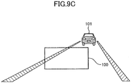
- FIGs. 9A, 9B , and 9C are yet other front views illustrating respective displaying examples of the HUD 200 viewed from the visual point of the driver 300 together with an environment in front of the vehicle 301.
- the zone of the forward environment of the vehicle 301 included in the image display area 100 depends on the driver's visual point position.
- the preceding vehicle 101 when the preceding vehicle 101 is viewed from the visual point position of the driver 300, the preceding vehicle 101 is approximately at the center of the left and right directions with respect to the image display area 100.
- the preceding vehicle 101 when the preceding vehicle 101 is viewed from the visual point position of the driver 300, the preceding vehicle 101 is to the left with respect to the image display area 100.
- FIG. 9C when the preceding vehicle 101 is viewed from the visual point position of the driver 300, the preceding vehicle 101 is to the right with respect to the image display area 100.
- the present embodiment for a case where, if an image displayed on the windshield 302 and a forward object viewable through the windshield 302 were viewed from the driver, the image would overlap with the forward object, it is controlled whether to display the image on the windshield 302; the brightness, the hue, the transparency, or the position of the image is controlled; or the like, according to the degree at which the image would overlap with the forward object. As a result, it is possible to effectively improve the visibility of the image displayed on the windshield 302 and the visibility of the forward object viewable through the windshield 302.
- the automotive HUD 200 has been described.
- the present invention is not limited to the automotive HUD 200.
- the present invention can be applied also to HUDs for other vehicles, to HDDs for other uses, and to image display apparatuses such as displays.
- a viewer corresponds to the driver 300, and an object at the same position as or near a position of an image display area 100 corresponds to the preceding vehicle 101 or the like.
- the color information values are represented by the RGB values. However, instead, other color information values such as lightness coordinates may be used.
- the present invention is not limited to this manner; it is also possible that at least one of these control modes is used. It is also possible to use yet another manner to perform the image display change.
- a method for detecting the visual point position is not limited to the above-described method using the driver camera 150. It is also possible to detect the visual point position by detecting the position of the head of the viewer to determine the visual point position. Further, as to the visual point position, it is also possible to use a viewer's visual point position that is previously determined on the basis of design values of the optical system 230 at a time when the HUD 200 is installed, as illustrated in FIG. 3 .
- Patent Document No. 1 Japanese Patent No. 4692595
Landscapes
- Engineering & Computer Science (AREA)
- Mechanical Engineering (AREA)
- Physics & Mathematics (AREA)
- Radar, Positioning & Navigation (AREA)
- Remote Sensing (AREA)
- General Physics & Mathematics (AREA)
- Transportation (AREA)
- Combustion & Propulsion (AREA)
- Chemical & Material Sciences (AREA)
- Theoretical Computer Science (AREA)
- Automation & Control Theory (AREA)
- Multimedia (AREA)
- General Engineering & Computer Science (AREA)
- Human Computer Interaction (AREA)
- Computer Hardware Design (AREA)
- Signal Processing (AREA)
- Optics & Photonics (AREA)
- Oral & Maxillofacial Surgery (AREA)
- General Health & Medical Sciences (AREA)
- Health & Medical Sciences (AREA)
- Instrument Panels (AREA)
- Fittings On The Vehicle Exterior For Carrying Loads, And Devices For Holding Or Mounting Articles (AREA)
- Closed-Circuit Television Systems (AREA)
Abstract
Description
- The present invention relates to an image display apparatus and an image display method.
- Technical development for a head-up display (hereinafter, referred to as a HUD) to be installed in a vehicle has been progressing. Expectations for a HUD have increased in the market, as an apparatus for a vehicle's driver to be able to recognize an alarm and information with a small amount of line-of-sight movement. In particular, along with advancement of automotive sensing technology typified by an ADAS (Advanced Driving Assistance System), a vehicle has been able to acquire various types of traveling environment information and vehicle occupant information. A HUD to be installed in a vehicle has also drawn attention as an "outlet of ADAS" that transmits the various types of traveling environment information and vehicle occupant information to the driver.
- A HUD to be installed in a vehicle displays an image as a virtual image ahead of the driver's visual point position by several meters. Thus, the HUD to be installed in the vehicle is capable of displaying the image as if the image were located in a real space in front of the vehicle. Such technology with which an image appears as if the image were present in a real space is called AR (Augmented Reality), and it is considered that the technology enables various types of information to be intuitionally displayed to the driver.
- An object of the disclosure is to improve a viewer's visibility for a case where, if an image displayed by an image display apparatus and an object at the same position as or near a position of the image were viewed from a position of the viewer's visual point, the image would overlap with the object.
- An image display apparatus includes a display section configured to display an image; a detecting section configured to detect an object at the same position as or near a position of the image; and a control section configured to control the image in response to determining overlap of the object with the image when viewed from a position of a visual point of a viewer viewing the image.
- It is possible to improve a viewer's visibility for a case where, if an image displayed by an image display apparatus and an object at the same position as or near a position of the image were viewed from a position of the viewer's visual point, the image would overlap with the object.
-
-
FIG. 1 is a front view illustrating one example of a virtual image displayed by an automotive HUD 200 (hereinafter, simply referred to as a HUD 200) according to an embodiment of the present invention in a state where the virtual image is superposed on a landscape, which a driver can see through awindshield 302, in front of avehicle 301. -
FIG. 2 is a partially-cutaway schematic side view schematically illustrating an inner arrangement of an automobile in which theHUD 200 according to the embodiment is installed. -
FIG. 3 is a block diagram schematically illustrating a configuration example of anoptical system 230 of theHUD 200 ofFIG. 2 . -
FIG. 4 is a block diagram illustrating a configuration example of acontrol system 250 of theHUD 200 ofFIG. 2 . -
FIG. 5 is a block diagram illustrating a general arrangement example of peripheral apparatuses of theHUD 200 ofFIG. 2 . -
FIG. 6A is a first front view illustrating a displaying example of theHUD 200 viewed from the visual point of adriver 300 together with an environment in front of thevehicle 301. -
FIG. 6B is a second front view illustrating a displaying example of theHUD 200 viewed from the visual point of thedriver 300 together with an environment in front of thevehicle 301. -
FIG. 7 is a flowchart illustrating one example of an image display change process implemented by thecontrol system 250 ofFIG. 4 . -
FIG. 8A is a third front view illustrating a displaying example of theHUD 200 viewed from the visual point of thedriver 300 together with an environment in front of thevehicle 301. -
FIG. 8B is a fourth front view illustrating a displaying example of theHUD 200 viewed from the visual point of thedriver 300 together with an environment in front of thevehicle 301. -
FIG. 9A is a fifth front view illustrating a displaying example of theHUD 200 viewed from the visual point of thedriver 300 together with an environment in front of thevehicle 301. -
FIG. 9B is a sixth front view illustrating a displaying example performed by theHUD 200 viewed from the visual point of thedriver 300 together with an environment in front of thevehicle 301. -
FIG. 9C is a seventh front view illustrating a displaying example of theHUD 200 viewed from the visual point of thedriver 300 together with an environment in front of thevehicle 301. - An embodiment according to the present invention that will now be described improves a viewer's visibility for a case where, for example, there is an object such as another vehicle in front of a vehicle, and, if an image displayed by a
HUD 200 and the object are viewed from a viewer, the image is superposed on the object. - Hereinafter, the embodiment of the present invention will be described with reference to the drawings. Note that the same reference signs are given to common elements of each embodiment that will now be described, and duplicate description will be omitted.
-
FIG. 1 is a forward view illustrating one example of a virtual image displayed by an automotive HUD 200 (hereinafter, simply referred to as a HUD 200) according to an embodiment of the present invention in a state where the virtual image is superposed on a landscape, which a driver can see through awindshield 302, in front of avehicle 301.FIG. 2 is a partially-cutaway schematic side view schematically illustrating an inner arrangement of an automobile in which theHUD 200 according to the embodiment is installed.FIG. 3 is a block diagram schematically illustrating a configuration example of an optical system of theHUD 200 ofFIG. 2 . TheHUD 200 is one example of an image display apparatus. - In
FIG. 2 , theHUD 200 according to the present embodiment is installed, for example, inside a dashboard of thevehicle 301 that is a traveling body as a mobile body. Projected light L that is image light emitted by theHUD 200 inside the dashboard is reflected by thewindshield 302 that is a light transmissive member, and thedriver 300 who is a viewer is irradiated with the projected light L. Thus, thedriver 300 can see a route navigation image or the like described later as the virtual image G. It is also possible that a combiner is installed as a light transmissive member on the inner wall of thewindshield 302, and the projected light L reflected by the combiner allows thedriver 300 to see the virtual image G. - At an upper portion of the
windshield 302, aforward shooting camera 110 and adriver camera 150 are arranged. Theforward shooting camera 110 takes a picture of a forward view. The forward view a picture of which is taken by theforward shooting camera 110 includes display information displayed by theHUD 200 onto thewindshield 302 and a background of the display information. That is, theforward shooting camera 110 takes a picture of the display information displayed by theHUD 200 onto thewindshield 302 and a picture of the background through thewindshield 302. The background a picture of which is taken by theforward shooting camera 110 through thewindshield 302 includes an environment in front of the vehicle 301 (i.e., a preceding vehicle, a road surface, and so forth). Thedriver camera 150 takes a picture of thedriver 300 for detecting the visual point position of thedriver 300. - According to the present embodiment, the
optical system 230 of theHUD 200 and so forth are designed in such a manner that the distance from thedriver 300 to the virtual image G is greater than or equal to 5 m. In contrast, in a conventional common automotive HUD, a distance from a driver to a virtual image is approximately 2 m. Generally speaking, a driver carefully watches a forward infinite point of the vehicle, or carefully watches a preceding vehicle at several tens of meters. In a case where the driver who has focused on such a distant position will see a virtual image at 2 m, the focal length varies greatly. As a result, the driver greatly moves the lenses of the eyes. Thus, a focus adjustment time taken until the virtual image is focused increases, a time is taken for the driver to recognize the contents of the virtual image, and the driver's eyeballs may become easily tired. Further, it is not easy for the driver to notice the contents of the virtual image, and it may be difficult to appropriately provide information to the driver with the virtual image. - In contrast, because the distance to the virtual image G is greater than or equal to 5 m in the present embodiment, an amount by which the
driver 300 moves the lenses of the eyes is reduced from the amount of the conventional case, and the focus adjustment time taken until the virtual image G is focused is reduced so that the driver can rapidly recognize the contents of the virtual image G. Further, it is possible to reduce tiredness of the eyeballs of thedriver 300. Further, thedriver 300 can easily notice the contents of the virtual image G, and it is possible to appropriately provide information to thedriver 300 with the virtual image G easily. In a case where the distance up to the virtual image G is greater than or equal to 5 m, thedriver 300 can focus on the virtual image G almost without performing convergence movement of the eyeballs. Accordingly, it is possible to suppress a reduction in an advantageous effect to allow a viewer to perceive a sense of distance (a change in the perceivable distance) and a sense of depth (a difference in the perceivable distance) with the use of motion parallax, the reduction otherwise occurring due to the eyeballs' convergence movement. Thus, it is possible to effectively obtain an advantageous effect for thedriver 300 to perceive information with the use of the sense of distance and the sense of depth. - The
optical system 230 of theHUD 200 illustrated inFIG. 3 includes red, green, and bluelaser light sources collimator lenses dichroic mirrors optical system 230 further includes a lightintensity adjustment section 207, anoptical scanning apparatus 208 as an optical scanning section, a free-curved mirror 209, amicro-lens array 210 as a light divergence member, and aprojection mirror 211 as a light reflecting member. Further, in alight source unit 220, thelaser light sources collimator lenses dichroic mirrors - As the
laser light sources light source 201R is, for example, 640 nm; the wavelength of the beam emitted by the green laserlight source 201G is, for example, 530 nm; and the wavelength of the beam emitted by the bluelaser light source 201B is, for example, 445 nm. - In the
HUD 200 according to the present embodiment, an intermediate image formed on themicro-lens array 210 is projected onto thewindshield 302 of thevehicle 301. Thus, thedriver 300 is able to see a magnified image of the intermediate image as the virtual image G. The laser light of the corresponding color emitted from each of thelaser light sources collimator lenses dichroic mirrors intensity adjustment section 207 adjusts the light intensity of the combined laser light, and thereafter the laser light is deflected by the mirror of theoptical scanning apparatus 208 to scan the free-curved mirror 209 two-dimensionally. The scanning light L' that scans the free-curved mirror 209 two-dimensionally as a result of being deflected by theoptical scanning apparatus 208 is reflected by the free-curved mirror 209 so that distortion is corrected, and thereafter is concentrated onto themicro-lens array 210 and renders the intermediate image G' on themicro-lens array 210. - Note that, according to the present embodiment, the
micro-lens array 210 is used as the light divergence member to divergently emit the beams corresponding to the respective pixels of the intermediate image G' (the respective points of the intermediate image). However, it is possible to use another light divergence member. Further, it is also possible to use a liquid crystal display (LCD) or a fluorescent display tube (VFD) to form the intermediate image G'. However, the laser scanning type as in the present embodiment is desirable for displaying the large virtual image G with high brightness. - In this regard, if a liquid crystal display (LCD) or a fluorescent display tube (VFD) were used, non-image segments included in the display area to which the virtual image G is displayed would be irradiated even slightly, and it would be difficult to completely prevent the non-image segments from being irradiated. As a result, the visibility of the forward landscape of the
vehicle 301 viewable through the non-image segments might degrade. In contrast, according to the laser scanning type as in the present embodiment, it is possible to completely prevent the non-image segments of the virtual image G in the display area from being irradiated by turning off thelaser light sources vehicle 301 through the non-image segments otherwise being degraded due to light emitted from theHUD 200, and it is possible to further improve the visibility of the forward landscape. - Further, for a case where the
HUD 200 gradually increases the brightness of an alarm image for, for example, alarming the driver, theHUD 200 performs a display control process to gradually increase the brightness of the alarm image from among various images included in the virtual image G. Also for the case of performing the display control process to increase the brightness of the partial image included in the virtual image G displayed by theHUD 200, the laser scanning type is desirable. If a liquid crystal display (LCD) or a fluorescent display tube (VFD) were used, also the brightness of images other than the alarm image included in the virtual image displayed by theHUD 200 might be increased together. Thus, if a liquid crystal display (LCD) or a fluorescent display tube (VFD) were used, it might be impossible to increase the difference in the brightness between the alarm image and the other images, and thus, it might be impossible to sufficiently obtain the advantageous effect to increase the degree of alarming by gradually increasing the brightness of the alarm image. - The
optical scanning apparatus 208 inclines the mirror in the main-scanning direction and in the sub-scanning direction with the use of a known actuator driving system such as a MEMS (Micro Electronic Mechanical Systems), to deflect the laser light that is incident on the mirror to two-dimensionally scan (raster scan) the free-curved mirror 209. Controlling the driving of the mirror is in synchronization with the light emission timing of thelaser light sources optical scanning apparatus 208 is not limited to having the above-described configuration. For example, an optical scanning apparatus using a mirror system including two mirrors that are oscillated or rotated about two mutually orthogonal axes may be used instead. -
FIG. 4 is a block diagram illustrating a configuration example of thecontrol system 250 of theHUD 200 ofFIG. 2 . As illustrated inFIG. 4 , thecontrol system 250 of theHUD 200 includes a FPGA (Field Programmable Gate Array) 251, a CPU (Central Processing Unit) 252, a ROM (Read-Only Memory) 253, a RAM (Random Access Memory) 254, an interface (hereinafter, referred to as I/F) 255, abus line 256, aLD driver 257, and aMEMS controller 258. TheFPGA 251 uses theLD driver 257 to control thelaser light sources light source unit 220, and uses theMEMS controller 258 to control theMEMS 208a of theoptical scanning apparatus 208. TheCPU 252 implements various functions of theHUD 200. TheROM 253 stores various programs such as an image processing program for theCPU 252 to implement the various functions of theHUD 200. TheRAM 254 is used as a work area of theCPU 252. The I/F 255 is an interface for communication with an external controller or the like, and is connected with, for example, avehicle navigation apparatus 400, a various-sensor apparatus 500, and so forth via a CAN (Controller Area Network) of thevehicle 301. - To the I/
F 255, also theforward shooting camera 110 is connected. Theforward shooting camera 110 takes a picture of a forward view of thevehicle 301, i.e., theforward shooting camera 110 takes a picture of the display information displayed by theHUD 200 on thewindshield 302, and takes a picture of the background of the display information through thewindshield 302. Further, to the I/F 255, also thedriver camera 150 is connected. Thedriver camera 150 is used to detect the visual point position of thedriver 300. Thecontrol system 250 performs image processing on the pictures of the display information and the background to convert the pictures into a picture that would be obtained if the display information and the background were viewed from the visual point position of thedriver 300 on the basis of the detected visual point position of thedriver 300. Thecontrol system 250 detects the visual point position of thedriver 300 by, for example, performing image analysis on the picture of the head of thedriver 300 taken by thedriver camera 150. -
FIG. 5 is a block diagram illustrating a general arrangement of peripheral apparatuses of theHUD 200 ofFIG. 2 . In the present embodiment, as information obtaining sections that obtain driver-provided information to be provided to thedriver 300 with the virtual image G, thevehicle navigation apparatus 400, the sensor apparatus, and so forth are installed. TheHUD 200 mainly includes theoptical system 230 that is one example of a display section and thecontrol system 250 that is one example of a control section. - As the
vehicle navigation apparatus 400 according to the present embodiment, a known vehicle navigation apparatus installed in an automobile or the like can be extensively used. Thevehicle navigation apparatus 400 outputs information to generate a route navigation image to be displayed as the virtual image G; the information is input to thecontrol system 250. The route navigation image includes, for example, as illustrated inFIG. 1 , images that indicate the number of lanes (travelling lanes) of the road on which thevehicle 301 is traveling; the distance to the position at which the next course change (turning right, turning left, entering a branch route, or the like) will be performed; the direction in which the course change will be performed, and so forth. These types of information are input to thecontrol system 250 from thevehicle navigation apparatus 400. As a result, under the control of thecontrol system 250, theHUD 200 displays as the virtual image G the route navigation images such as a travellinglane image 711, avehicular gap image 712, acourse instruction image 721, a remainingdistance image 722, an intersection (or the like)name image 723, and so forth in an upper image display area A. - Further, according to the image example illustrated in
FIG. 1 , theHUD 200 displays, as the virtual image G, images that indicate road-specific information (the road name, the speed limit, and so forth) in a lower image display area B. Also the road-specific information is input to thecontrol system 250 from thevehicle navigation apparatus 400. As a result, under the control of thecontrol system 250, theHUD 200 displays aroad name image 701, aspeed limit image 702, a no-passingindication image 703, and so forth corresponding to the road-specific information as the virtual image in the lower image display area B. - The
sensor apparatus 500 ofFIG. 5 includes one or more sensors for detecting various types of information that indicate the behavior of thevehicle 301, the state of thevehicle 301, the surrounding conditions of thevehicle 301, and so forth. From thesensor apparatus 500, sensing information to be used to generate images to be displayed as the virtual image G is output; the sensing information is input to thecontrol system 250. For example, according to the image example illustrated inFIG. 1 , theHUD 200 displays a vehicle speed image 704 (a character image "83km/h" in the example ofFIG. 1 ) that indicates the speed of thevehicle 301 in the lower image display area B. That is, vehicle speed information that is included in CAN information of thevehicle 301 is input to thecontrol system 250 from thesensor apparatus 500; under the control ofcontrol system 250, theHUD 200 displays the character image indicating the vehicle speed in the lower image display area B as the virtual image G. - As the
sensor apparatus 500, in addition to the sensor to detect the speed of thevehicle 301, (1) a laser radar apparatus or a photographing apparatus for detecting the distances to other vehicles, pedestrians, and constructions (guardrails, telegraph poles, and so forth) in the surroundings (forward, sideward, and backward) of thevehicle 301, and sensors for detecting the vehicle surrounding information (the ambient temperature, the lightness outside, the weather, and so forth); (2) sensors for detecting driving operations of the driver 300 (a braking operation, the accelerator position, and so forth); (3) a sensor for detecting the remaining fuel amount in the fuel tank of thevehicle 301; and (4) sensors for detecting states of various on-board apparatuses such as the engine, the battery, and so forth can be included for example. The information that indicates the detection results of thesensor apparatus 500 is sent to thecontrol system 250 so that theHUD 200 can provide the information to thedriver 300 in the form of the virtual image G. - Next, the virtual image G displayed by the
HUD 200 will be described. In theHUD 200 according to the present embodiment, the driver-provided information to be provided to thedriver 300 by the virtual image G can include any information as long as the information is useful for thedriver 300. According to the present embodiment, for the sake of convenience, the driver-provided information to be provided to the driver is generally classified into passive information and active information. - The passive information is information that is passively recognized by the
driver 300 at a time when predetermined information provision conditions are satisfied. Therefore, information that is provided to thedriver 300 at a set time stored in theHUD 200 is included in the passive information. Information such that a time at which the information is provided has a fixed relationship with the contents of the information is included in the passive information. As the passive information, for example, information concerning safety while driving, route navigation information, and so forth can be cited. As the information concerning safety while driving, information (the vehicular gap image 712) that indicates the vehicular gap between thevehicle 301 and the preceding vehicle 350, emergency information concerning driving (alarm information such as emergency operation instruction information that gives instruction to the driver to perform an emergency operation; attention attracting information; or the like), and so forth can be cited. The route navigation information is information of route guidance for a predetermined destination, and can be the same as information that is provided to a driver by a known vehicle navigation apparatus. As the route navigation information, travelling lane instruction information (the travelling lane image 711) for giving instruction for the travelling lane to travel at an immediate intersection; course change instruction information for giving an instruction for a course change operation at the intersection or the branch point of a next course change from the straight-ahead direction; and so forth can be cited. As the course change instruction information, course instruction information (the course instruction image 721) to give an instruction for a course to select at the intersection or the branch point; information (the remaining distance image 722) indicating the remaining distance up to the intersection or the like of the course change; information (the intersection (or the like) name image 723) indicating the name of the intersection or the like; and so forth can be cited. - The active information is information to be actively recognized by the
driver 300 at a time that is determined by thedriver 300 himself or herself. The active information is such that it is sufficient for the active information to be provided to thedriver 300 at a time desired by thedriver 300. For example, information such that a time at which the information is provided has little or no relationship with the contents of the information is included in the active information. The active information is information that is provided at a time desired by thedriver 300, and therefore, is information that is displayed continuously for a rather long time or is displayed continuously at all times. For example, the road-specific information for the road on which thevehicle 301 is traveling, the vehicle speed information (the vehicle speed image 704) of thevehicle 301, the current time information, and so forth can be cited. As the road-specific information, information concerning the road and useful for thedriver 300 such as information (the road name image 701) indicating the name of the road; information (thespeed limit image 702 or the no-passing indication image 703) indicating regulation contents concerning the road; and so forth can be cited for example. - According to the present embodiment, the thus generally classified passive information and active information are displayed in the respective display areas where the virtual images G can be displayed. Actually, according to the present embodiment, as areas in which the
HUD 200 displays the virtual images, two display areas arranged vertically are set. In the upper image display area A of these two display areas, mainly passive information images corresponding to the passive information are displayed. In the lower image display area B of these two display areas, mainly active information images corresponding to the active information are displayed. Note that, for a case where some of the active information images are displayed in the upper image display area A, these active information images are displayed in such a manner that the visibility of the passive information images displayed in the upper image display area A has priority over the visibility of these active information images. - Further, according to the present embodiment, as the virtual image G displayed by the
HUD 200, a stereoscopic image that is expressed with the use of a stereoscopic approach is used. Actually, as thevehicular gap image 712 and the travellinglane image 711 displayed in the upper image display area A in which the virtual image is displayed by theHUD 200, a perspective image that is expressed with the use of perspective is used. - In more detail, the five horizontal lines included in the
vehicular gap image 712 are displayed in such a manner that the higher horizontal line is shorter. Thus, thevehicular gap image 712 is expressed as a perspective image directed toward a single vanishing point according to a perspective drawing method. Especially, according to the present embodiment, thevehicular gap image 712 is formed in such a manner that the vanishing point can be determined near the gazing point of thedriver 300. As a result, thedriver 300 can easily perceive the sense of depth of thevehicular gap image 712. In addition, according to the present embodiment, thevehicular gap image 712 as the perspective image is displayed in such a manner that the higher horizontal line is narrower or the brightness of the higher horizontal line is lower. As a result, thedriver 300 can further easily perceive the sense of depth of thevehicular gap image 712. -
FIGs. 6A and 6B are front views each illustrating an example displayed by theHUD 200 viewed from the visual point of thedriver 300 together with a forward environment of thevehicle 301. As described above, being viewed from the visual point of the driver (movable in the left and right directions, in the forward and backward directions, and in the vertical directions of the vehicle 301), theimage display area 100 in which theHUD 200 displays the virtual image overlaps with the road surface on which thevehicle 301 is travelling. In this regard, depending on the position of the precedingvehicle 101, as illustrated inFIG. 6B , theimage display area 100 may overlap with the precedingvehicle 101. In this case, the visibility of the image displayed in theimage display area 100 and the visibility of the precedingvehicle 101 may greatly degrade. -
FIG. 7 is a flowchart illustrating one example of an image display change process implemented by thecontrol system 250 ofFIG. 4 . The present embodiment has the following three control modes (1), (2), and (3) for controlling an image for a case where, if the image displayed by theHUD 200 in theimage display area 100 and the precedingvehicle 101 were viewed by thedriver 300, the image would overlap with the precedingvehicle 101. - The partial erasing mode is a control mode such that a part of the image displayed in the
image display area 100 is erased. - The image display value control mode is a control mode such that display values (i.e., at least one type of values out of three types of values, i.e., brightness; hues that are, for example, ratios among R (red) values, G (green) values, and B (blue) values; and alpha values) of the entirety or a part of the image displayed in the
image display area 100 are changed. - The image position change mode is a control mode such that the position of the image displayed in the
image display area 100 is changed. - Note that the alpha values are display values representing transparency of the displayed image.
- In step S1 of
FIG. 7 , thecontrol system 250 obtains a picture of the precedingvehicle 101 as a result of causing theforward shooting camera 110 to take a picture of a forward environment of thevehicle 301. Next, in step S2, thecontrol system 250 obtains the visual point position of thedriver 300 as a result of causing thedriver camera 150 to take a picture of the head of thedriver 300. Then, in step S3, thecontrol system 250 causes theHUD 200 to display the display information. Next, in step S4, thecontrol system 250 determines whether, if the display information image displayed by theHUD 200 and the precedingvehicle 101 were viewed from the driver's visual point position, the display information image would overlap with the precedingvehicle 101. - In detail, in step S4, the
control system 250 performs image processing on the pictures that include the picture of the display information displayed on thewindshield 302 by theHUD 200 and taken by theforward shooting camera 110 in step S3 and the picture of the precedingvehicle 101 taken by theforward shooting camera 110 in step S1, on the basis of the visual point position of thedriver 300 obtained in step S2. Through the image processing, thecontrol system 250 converts the pictures that include the display information image displayed on thewindshield 302 and the background of the display information image viewed through thewindshield 302 into a picture that would be obtained from the visual point position of thedriver 300. As a result, thecontrol system 250 can determine whether, if the display information image and the precedingvehicle 101 were viewed from the driver's visual point position, the display information image would overlap with the precedingvehicle 101. Note that, for the sake of convenience of explanation, the precedingvehicle 101 is assumed as an object for which it is determined whether the object would overlap with the image displayed by theHUD 200 on thewindshield 302. However, the object is not limited to the precedingvehicle 101. The object may be, instead of the "precedingvehicle 101", any object that adversely affects the visibility of thedriver 300 because of overlapping with the image displayed by theHUD 200 on thewindshield 302, where said any object may be the precedingvehicle 101. - An actual method to obtain the picture that would be obtained from the visual point position of the
driver 300 may be, for example, the following method. That is, assuming that theforward shooting camera 110 includes two cameras for example, the two cameras are used to take respective pictures of the precedingvehicle 101, and the position of the preceding vehicle 101 (with respect to the vehicle 301) is determined according to the triangulation method. Next, on the basis of the thus obtained position of the precedingvehicle 101 and the detected visual point position of thedriver 300, the position of the precedingvehicle 101 on thewindshield 302 if the precedingvehicle 101 were viewed from the visual point of thedriver 300 is determined. Next, on the basis of the taken picture of the display information image displayed by theHUD 200 on thewindshield 302, the reflection position and the reflection angle at which the display information image is reflected by thewindshield 302 are determined. Because the positional relationship between theforward shooting camera 110 and thewindshield 302 is known, it is possible to determine the reflection position and the reflection angle on the basis of the position of the display information image on thewindshield 302. Next, on the basis of the reflection position and the reflection angle, the position in theHUD 200 from which the display information image is emitted is determined. Because the positional relationship between theHUD 200 and thewindshield 302 is known, it is possible to determine the position in theHUD 200 from which the display information image is emitted on the basis of the reflection position and the reflection angle. Next, on the basis of the position in theHUD 200 from which the display information image is emitted, the position of the display information image on thewindshield 302 if the display information image were viewed from the driver's visual point is determined. By thus determining the positional relationship between the precedingvehicle 101 and the display information image on thewindshield 302 included in the picture that would be obtained if the precedingvehicle 101 and the display information image were viewed from the visual point of thedriver 300, it is possible to obtain the picture that includes the precedingvehicle 101 and the display information image when viewed from the visual point of thedriver 300. - In response to the determination result YES in step S4, the
control system 250 proceeds to step S5. In response to the determination result NO in step S4, thecontrol system 250 returns to step S1. - In step S5, the
control system 250 determines whether thecontrol system 250 is in the above-mentioned "partially erasing mode". In response to the determination result YES in step S5, thecontrol system 250 proceeds to step S6. In response to the determination result NO in step S5, thecontrol system 250 proceeds to step S7. - In step S6, the
control system 250 partially erases the display information displayed by theHUD 200, and returns to step S1. - Next, in step S7, the
control system 250 determines whether thecontrol system 250 is in the above-mentioned "image display value control mode". In response to the determination result YES in step S7, thecontrol system 250 proceeds to step S8. In response to the determination result NO in step S7, thecontrol system 250 proceeds to step S9. - In step S8, the
control system 250 changes the display values (i.e., at least one type of values out of three types of values, i.e., brightness; hues that are, for example, ratios among R (Red) values, G (Green) values, and B (Blue) values; and alpha values) of the image displayed by theHUD 200, and returns to step S1. - Next, in step S9, the
control system 250 determines whether thecontrol system 250 is in the above-mentioned "image position change mode". In response to the determination result YES in step S9, thecontrol system 250 proceeds to step S10. In response to the determination result NO in step S9, thecontrol system 250 returns to step S1. - In step S10, the
control system 250 changes the position at which theHUD 200 displays the image, and returns to step S1. - According to the present embodiment, the display information displayed by the
HUD 200 includes, for example, the following three types of display information. - (1) Speed display information
- (2) Navigation display information (for example, "turn left 2 km ahead")
- (3) Alarm display information of, for example, approaching a preceding vehicle
-
FIG. 8A is a front view illustrating a displaying example of theHUD 200 viewed from the visual point of thedriver 300 together with an environment in front of thevehicle 301. In the example ofFIG. 8A , the partially erasing mode is used, and a part (for example, the navigation display information 102 (because of lower importance level) above the speed display information 103) is erased in theimage display area 100. -
FIG. 8B is a front view illustrating another displaying example of theHUD 200 viewed from the visual point of thedriver 300 together with an environment in front of thevehicle 301. In the example ofFIG. 8B , the image position change mode is used, and, in order to prevent thenavigation display information 102 from overlapping with the precedingvehicle 101, thenavigation display information 102 is shifted to below thespeed display information 103. Note that, as illustrated in the example ofFIG. 6A , originally, thenavigation display information 102 is displayed above thespeed display information 103. -
FIGs. 9A, 9B , and9C are yet other front views illustrating respective displaying examples of theHUD 200 viewed from the visual point of thedriver 300 together with an environment in front of thevehicle 301. - The zone of the forward environment of the
vehicle 301 included in theimage display area 100 depends on the driver's visual point position. According to the example ofFIG. 9B , when the precedingvehicle 101 is viewed from the visual point position of thedriver 300, the precedingvehicle 101 is approximately at the center of the left and right directions with respect to theimage display area 100. According to the example ofFIG. 9A , when the precedingvehicle 101 is viewed from the visual point position of thedriver 300, the precedingvehicle 101 is to the left with respect to theimage display area 100. According to the example ofFIG. 9C , when the precedingvehicle 101 is viewed from the visual point position of thedriver 300, the precedingvehicle 101 is to the right with respect to theimage display area 100. - Thus, to what degree an object such as the preceding
vehicle 101 in the forward environment would overlap with theimage display area 100 depends on the visual point position of thedriver 300. Therefore, by taking into consideration the visual point position of thedriver 300 when thecontrol system 250 determines to what degree an object such as the precedingvehicle 101 in the forward environment would overlap with theimage display area 100, it is possible to implement displaying the image in a state of further reducing obstructiveness. - Next, differences of the above-described embodiment from the disclosed art of the patent document No. 1 will now be described.
- According to the patent document No. 1, in order to provide a vehicular information display system that can display a large amount of information without interfering driver's visibility, transparency of an image is adjusted and a position to project the image is changed when the image overlaps with an object in front of a vehicle. However, by controlling only the transparency of the image and the position to project the image, it may be insufficient to implement improving the visibility, reducing a time for understanding information, avoiding misrecognition and annoyance, and so forth. Further, concerning a change in a driver's visual point position, the disclosed art of the patent document No. 1 may not have sufficient robustness against a change in a driving situation of a driver. According to the present embodiment, for a case where, if an image displayed on the
windshield 302 and a forward object viewable through thewindshield 302 were viewed from the driver, the image would overlap with the forward object, it is controlled whether to display the image on thewindshield 302; the brightness, the hue, the transparency, or the position of the image is controlled; or the like, according to the degree at which the image would overlap with the forward object. As a result, it is possible to effectively improve the visibility of the image displayed on thewindshield 302 and the visibility of the forward object viewable through thewindshield 302. - In the above-described embodiment, the
automotive HUD 200 has been described. However, the present invention is not limited to theautomotive HUD 200. The present invention can be applied also to HUDs for other vehicles, to HDDs for other uses, and to image display apparatuses such as displays. In these cases, a viewer corresponds to thedriver 300, and an object at the same position as or near a position of animage display area 100 corresponds to the precedingvehicle 101 or the like. - In the above-described embodiment, the color information values are represented by the RGB values. However, instead, other color information values such as lightness coordinates may be used.
- In the above-described embodiment, in the image display change process of
FIG. 7 , the partially erasing mode, the image display value control mode, and the image position change mode are used. However, the present invention is not limited to this manner; it is also possible that at least one of these control modes is used. It is also possible to use yet another manner to perform the image display change. - In the above-described embodiment, it is determined whether, if the preceding
vehicle 101 or the like and the image displayed on thewindshield 302 were viewed from the visual point position of the viewer who is thedriver 300, the precedingvehicle 101 or the like would overlap with the image. In this regard, a method for detecting the visual point position is not limited to the above-described method using thedriver camera 150. It is also possible to detect the visual point position by detecting the position of the head of the viewer to determine the visual point position. Further, as to the visual point position, it is also possible to use a viewer's visual point position that is previously determined on the basis of design values of theoptical system 230 at a time when theHUD 200 is installed, as illustrated inFIG. 3 . - Thus, the image display apparatuses and the image display methods have been described with the embodiments. However, the present invention is not limited to the embodiments, and various modifications and improvements can be made within the scope of the present invention.
- The present international application claims priority to Japanese Patent Application No.
2016-021737 filed February 8, 2016 2016-021737 -
100 image display area 101 preceding vehicle 110 forward shooting camera 150 driver camera 200 automotive HUD 211 proj ection mirror 220 light source unit 230 optical system 250 control system 251 FPGA 252 CPU 253 ROM 254 RAM 300 driver 301 vehicle 302 windshield 400 the vehicle navigation apparatus 500 sensor apparatus 712 vehicular gap image A upper image display area B lower image display area - Patent Document No. 1: Japanese Patent No.
4692595
Claims (8)
- An image display apparatus comprising:a display section configured to display an image;a first detecting section configured to detect an object at the same position as or near a position of the image; anda control section configured to control the image in response to determining overlap of the object with the image when viewed from a position of a visual point of a viewer viewing the image.
- The image display apparatus according to claim 1, further comprising a second detecting section configured to detect the position of the visual point of the viewer.
- The image display apparatus according to claim 1 or 2, wherein
the control section is configured to, in response to determining overlap of the object with the image when viewed from the position of the visual point of the viewer viewing the image, perform any one of control to erase a part of the image, control to change a display value of all or a part of the image, and control to change a position to display the image. - The image display apparatus according to claim 3, wherein
the display value includes at least one of brightness, hue, and an alpha value. - The image display apparatus according to any one of claims 1-4, comprising a head-up display that displays the image to a windshield of a vehicle or a combiner.
- An image display method that is implemented by an image display apparatus that includes a display section configured to display an image, the image display method comprising:detecting an object at the same position as or near a position of the image; andcontrolling the image in response to determining overlap of the object with the image when viewed from a position of a visual point of a viewer viewing the image.
- The image display method according to claim 6, further comprising detecting the position of the visual point of the viewer.
- The image display method according to claim 6 or 7, wherein
the controlling the image includes, in response to determining overlap of the object with the image when viewed from the position of the visual point of the viewer viewing the image, performing any one of control to erase a part of the image, control to change a display value of all or a part of the image, and control to change a position to display the image.
Applications Claiming Priority (2)
| Application Number | Priority Date | Filing Date | Title |
|---|---|---|---|
| JP2016021737 | 2016-02-08 | ||
| PCT/JP2017/000997 WO2017138297A1 (en) | 2016-02-08 | 2017-01-13 | Image display device and method for displaying image |
Publications (3)
| Publication Number | Publication Date |
|---|---|
| EP3416377A1 true EP3416377A1 (en) | 2018-12-19 |
| EP3416377A4 EP3416377A4 (en) | 2019-02-20 |
| EP3416377B1 EP3416377B1 (en) | 2021-06-16 |
Family
ID=59562993
Family Applications (1)
| Application Number | Title | Priority Date | Filing Date |
|---|---|---|---|
| EP17750022.0A Active EP3416377B1 (en) | 2016-02-08 | 2017-01-13 | Image display apparatus and image display method |
Country Status (4)
| Country | Link |
|---|---|
| US (1) | US10890762B2 (en) |
| EP (1) | EP3416377B1 (en) |
| JP (1) | JP6806097B2 (en) |
| WO (1) | WO2017138297A1 (en) |
Families Citing this family (22)
| Publication number | Priority date | Publication date | Assignee | Title |
|---|---|---|---|---|
| JP6726674B2 (en) * | 2015-10-15 | 2020-07-22 | マクセル株式会社 | Information display device |
| WO2018147066A1 (en) * | 2017-02-08 | 2018-08-16 | 株式会社デンソー | Display control apparatus for vehicles |
| CN108628087B (en) * | 2017-03-20 | 2020-11-06 | 成都理想境界科技有限公司 | A projection device and spatial imaging method |
| CN107323375B (en) * | 2017-06-27 | 2019-12-03 | 京东方科技集团股份有限公司 | In-vehicle display system, traffic equipment and image display method |
| CA3013888C (en) * | 2017-08-11 | 2025-09-23 | 8259402 Canada Inc. | Transmissive aerial image display |
| JP6991794B2 (en) * | 2017-08-29 | 2022-01-13 | 矢崎総業株式会社 | Vehicle display device and display control method |
| US20190161010A1 (en) * | 2017-11-30 | 2019-05-30 | Panasonic Automotive Systems Company Of America, Division Of Panasonic Corporation Of North America | High visibility head up display (hud) |
| JP6945933B2 (en) * | 2017-12-27 | 2021-10-06 | アルパイン株式会社 | Display system |
| JP6838626B2 (en) * | 2018-08-22 | 2021-03-03 | 株式会社デンソー | Display control device and display control program |
| WO2020039855A1 (en) * | 2018-08-22 | 2020-02-27 | 株式会社デンソー | Display control device, display control program, and continuous tangible computer-readable medium thereof |
| JP1632766S (en) * | 2018-09-10 | 2019-06-03 | ||
| CN112930557B (en) * | 2018-09-26 | 2025-09-02 | 相干逻辑公司 | Any world view generation |
| JP7222285B2 (en) | 2019-03-20 | 2023-02-15 | 株式会社リコー | DISPLAY CONTROL DEVICE, DISPLAY DEVICE, DISPLAY SYSTEM, MOBILE OBJECT, PROGRAM, IMAGE GENERATION METHOD |
| KR102757348B1 (en) * | 2019-06-25 | 2025-01-20 | 현대모비스 주식회사 | Control system using gesture in vehicle |
| PL3839411T3 (en) * | 2019-12-17 | 2023-12-27 | John Cockerill Defense SA | INTELLIGENT SYSTEM FOR CONTROLING THE TURRET FUNCTIONS OF A COMBAT VEHICLE |
| JP7767738B2 (en) * | 2021-06-01 | 2025-11-12 | マツダ株式会社 | Head-up display device |
| WO2022264294A1 (en) * | 2021-06-16 | 2022-12-22 | 三菱電機株式会社 | Aerial image display device and aerial image display method |
| JP2024074656A (en) * | 2022-11-21 | 2024-05-31 | トヨタ自動車株式会社 | Vehicle display control device, vehicle display control method, and vehicle display control program |
| JP2025075869A (en) * | 2023-10-31 | 2025-05-15 | 株式会社小糸製作所 | Image projection device and image projection method |
| JP7798851B2 (en) * | 2023-11-30 | 2026-01-14 | 本田技研工業株式会社 | Projection management device and program |
| USD1117255S1 (en) * | 2023-12-19 | 2026-03-10 | Lg Electronics Inc. | Display panel with animated graphical user interface |
| CN119078510A (en) * | 2024-09-02 | 2024-12-06 | 江苏泽景汽车电子股份有限公司 | A method, device, medium and projection device for controlling display brightness |
Family Cites Families (38)
| Publication number | Priority date | Publication date | Assignee | Title |
|---|---|---|---|---|
| JP4297045B2 (en) * | 2004-12-14 | 2009-07-15 | 株式会社デンソー | Display control apparatus and program for head-up display |
| JP2006309090A (en) | 2005-02-21 | 2006-11-09 | Ricoh Co Ltd | Scanning optical system, optical scanning apparatus, image forming apparatus, and color image forming apparatus |
| JP4500738B2 (en) | 2005-06-20 | 2010-07-14 | 株式会社リコー | Optical scanning device and image forming device |
| US7876486B2 (en) | 2006-03-08 | 2011-01-25 | Ricoh Company, Limited | Optical scanning apparatus, optical writing apparatus, and image forming apparatus |
| US7688491B2 (en) | 2006-09-15 | 2010-03-30 | Ricoh Company, Ltd. | Diffractive-optical element, scanning optical system, optical scanner, and image forming apparatus |
| JP4976092B2 (en) | 2006-09-19 | 2012-07-18 | 株式会社リコー | Optical scanning device and image forming apparatus using the same |
| US8045248B2 (en) | 2007-03-09 | 2011-10-25 | Ricoh Company, Ltd. | Optical scanning device and image forming apparatus |
| JP2009053379A (en) | 2007-08-27 | 2009-03-12 | Ricoh Co Ltd | Optical scanning apparatus and image forming apparatus |
| JP2009053378A (en) | 2007-08-27 | 2009-03-12 | Ricoh Co Ltd | Optical scanning apparatus and image forming apparatus |
| JP2009274542A (en) * | 2008-05-14 | 2009-11-26 | Honda Motor Co Ltd | Head up display device |
| JP4692595B2 (en) | 2008-08-25 | 2011-06-01 | 株式会社デンソー | Information display system for vehicles |
| JP2011013289A (en) | 2009-06-30 | 2011-01-20 | Ricoh Co Ltd | Optical scanning device and image forming apparatus |
| US8531766B2 (en) | 2009-07-02 | 2013-09-10 | Ricoh Company, Limited | Polarization-separation device, optical scanning apparatus, and image forming apparatus |
| JP5679175B2 (en) | 2010-03-24 | 2015-03-04 | 株式会社リコー | Optical scanning apparatus and image forming apparatus |
| JP5691633B2 (en) | 2010-06-25 | 2015-04-01 | 株式会社リコー | Optical scanning apparatus and image forming apparatus |
| JP5803184B2 (en) | 2010-11-19 | 2015-11-04 | 株式会社リコー | Image projection apparatus and memory access method |
| JP2013061554A (en) | 2011-09-14 | 2013-04-04 | Ricoh Co Ltd | Image forming apparatus, and vehicle with image forming apparatus mounted thereon |
| JP2013203374A (en) * | 2012-03-29 | 2013-10-07 | Denso It Laboratory Inc | Display device for vehicle, control method therefor, and program |
| JP2012252347A (en) | 2012-07-24 | 2012-12-20 | Ricoh Co Ltd | Optical scanner, optical writing apparatus, and image forming apparatus |
| JP6265140B2 (en) | 2012-12-21 | 2018-01-24 | 株式会社リコー | Microlens array and moving body |
| JP6237124B2 (en) | 2012-12-21 | 2017-11-29 | 株式会社リコー | Two-dimensional image display device, optical scanning device for two-dimensional image display device, scanned surface element, and moving body |
| US9158124B2 (en) | 2012-12-21 | 2015-10-13 | Ricoh Company, Ltd. | Image display device and vehicle incorporating the same |
| JP6237123B2 (en) | 2012-12-21 | 2017-11-29 | 株式会社リコー | Two-dimensional image display device, optical scanning device for two-dimensional image display device, scanned surface element, and moving body |
| JP5682692B2 (en) | 2012-12-21 | 2015-03-11 | 株式会社リコー | Image display device |
| JP2014181927A (en) * | 2013-03-18 | 2014-09-29 | Aisin Aw Co Ltd | Information provision device, and information provision program |
| JP2014185926A (en) * | 2013-03-22 | 2014-10-02 | Aisin Aw Co Ltd | Guidance display system |
| JP5786905B2 (en) | 2013-07-18 | 2015-09-30 | 株式会社リコー | Optical scanning apparatus and image forming apparatus |
| JP6387589B2 (en) | 2013-08-30 | 2018-09-12 | 株式会社リコー | Image forming apparatus, vehicle, and control method of image forming apparatus |
| JP6253417B2 (en) * | 2014-01-16 | 2017-12-27 | 三菱電機株式会社 | Vehicle information display control device |
| JP2015138084A (en) | 2014-01-21 | 2015-07-30 | 株式会社リコー | Video display device and video display system |
| JP5817855B2 (en) | 2014-01-22 | 2015-11-18 | 株式会社リコー | Optical scanning apparatus and image forming apparatus |
| JP6524417B2 (en) | 2014-02-05 | 2019-06-05 | パナソニックIpマネジメント株式会社 | Display device for vehicle and display method of display device for vehicle |
| JP6340807B2 (en) | 2014-02-05 | 2018-06-13 | 株式会社リコー | Image display device and moving body |
| JP6555507B2 (en) | 2014-05-12 | 2019-08-07 | 株式会社リコー | Image display device and moving body |
| JP6638198B2 (en) | 2014-05-12 | 2020-01-29 | 株式会社リコー | Image display device and moving object |
| JP6617947B2 (en) | 2014-05-15 | 2019-12-11 | 株式会社リコー | Image display device and image display system |
| JP6485732B2 (en) | 2014-12-10 | 2019-03-20 | 株式会社リコー | Information providing apparatus, information providing method, and information providing control program |
| EP3093194B1 (en) | 2015-04-24 | 2021-09-22 | Ricoh Company, Ltd. | Information provision device |
-
2017
- 2017-01-13 EP EP17750022.0A patent/EP3416377B1/en active Active
- 2017-01-13 WO PCT/JP2017/000997 patent/WO2017138297A1/en not_active Ceased
- 2017-01-13 JP JP2017566554A patent/JP6806097B2/en active Active
-
2018
- 2018-07-26 US US16/046,470 patent/US10890762B2/en active Active
Also Published As
| Publication number | Publication date |
|---|---|
| US10890762B2 (en) | 2021-01-12 |
| EP3416377B1 (en) | 2021-06-16 |
| WO2017138297A1 (en) | 2017-08-17 |
| JPWO2017138297A1 (en) | 2018-11-15 |
| US20180373030A1 (en) | 2018-12-27 |
| EP3416377A4 (en) | 2019-02-20 |
| JP6806097B2 (en) | 2021-01-06 |
Similar Documents
| Publication | Publication Date | Title |
|---|---|---|
| US10890762B2 (en) | Image display apparatus and image display method | |
| US10551619B2 (en) | Information processing system and information display apparatus | |
| US12361850B2 (en) | Information provision device, information provision method, and recording medium storing information provision program for a vehicle display | |
| US10852818B2 (en) | Information provision device and information provision method | |
| US10948716B2 (en) | Image display device and image display method | |
| US10696159B2 (en) | Information providing apparatus | |
| KR102222091B1 (en) | Display device, moving body device, manufacturing method of display device, and display method | |
| EP3416376B1 (en) | Image display device, car onboard system, and image display method | |
| JP2017211366A (en) | Mobile body system and information display device | |
| EP3415971A1 (en) | Information display device | |
| JPWO2017138527A1 (en) | Information provision device | |
| JP6512475B2 (en) | INFORMATION PROVIDING DEVICE, INFORMATION PROVIDING METHOD, AND INFORMATION PROVIDING CONTROL PROGRAM | |
| EP3348433B1 (en) | Information display device and vehicle apparatus | |
| JP2016109645A (en) | Information providing device, information providing method, and control program for providing information | |
| JP6876277B2 (en) | Control device, display device, display method and program | |
| JP2016107947A (en) | Information providing device, information providing method, and control program for providing information | |
| JP7027992B2 (en) | Image display device, moving object, image display method and program | |
| JP7037764B2 (en) | Travel route guidance device, mobile body, travel route guidance method and program | |
| JP7552018B2 (en) | In-vehicle display device and program | |
| WO2021153454A1 (en) | Image display apparatus, image display method, program, and non-transitory recording medium |
Legal Events
| Date | Code | Title | Description |
|---|---|---|---|
| STAA | Information on the status of an ep patent application or granted ep patent |
Free format text: STATUS: THE INTERNATIONAL PUBLICATION HAS BEEN MADE |
|
| PUAI | Public reference made under article 153(3) epc to a published international application that has entered the european phase |
Free format text: ORIGINAL CODE: 0009012 |
|
| STAA | Information on the status of an ep patent application or granted ep patent |
Free format text: STATUS: REQUEST FOR EXAMINATION WAS MADE |
|
| 17P | Request for examination filed |
Effective date: 20180725 |
|
| AK | Designated contracting states |
Kind code of ref document: A1 Designated state(s): AL AT BE BG CH CY CZ DE DK EE ES FI FR GB GR HR HU IE IS IT LI LT LU LV MC MK MT NL NO PL PT RO RS SE SI SK SM TR |
|
| AX | Request for extension of the european patent |
Extension state: BA ME |
|
| A4 | Supplementary search report drawn up and despatched |
Effective date: 20190118 |
|
| RIC1 | Information provided on ipc code assigned before grant |
Ipc: H04N 7/18 20060101AFI20190114BHEP Ipc: G09G 5/00 20060101ALI20190114BHEP Ipc: G01C 21/36 20060101ALI20190114BHEP Ipc: G01C 21/34 20060101ALI20190114BHEP Ipc: B60R 11/02 20060101ALI20190114BHEP Ipc: B60K 35/00 20060101ALI20190114BHEP |
|
| DAV | Request for validation of the european patent (deleted) | ||
| DAX | Request for extension of the european patent (deleted) | ||
| STAA | Information on the status of an ep patent application or granted ep patent |
Free format text: STATUS: EXAMINATION IS IN PROGRESS |
|
| 17Q | First examination report despatched |
Effective date: 20191120 |
|
| GRAP | Despatch of communication of intention to grant a patent |
Free format text: ORIGINAL CODE: EPIDOSNIGR1 |
|
| STAA | Information on the status of an ep patent application or granted ep patent |
Free format text: STATUS: GRANT OF PATENT IS INTENDED |
|
| INTG | Intention to grant announced |
Effective date: 20210128 |
|
| RIN1 | Information on inventor provided before grant (corrected) |
Inventor name: KATAGIRI, KEITA Inventor name: SAISHO, KENICHIROH Inventor name: KUSANAGI, MASATO Inventor name: YAMAGUCHI, HIROSHI Inventor name: SUZUKI, YUUKI |
|
| GRAS | Grant fee paid |
Free format text: ORIGINAL CODE: EPIDOSNIGR3 |
|
| GRAA | (expected) grant |
Free format text: ORIGINAL CODE: 0009210 |
|
| STAA | Information on the status of an ep patent application or granted ep patent |
Free format text: STATUS: THE PATENT HAS BEEN GRANTED |
|
| AK | Designated contracting states |
Kind code of ref document: B1 Designated state(s): AL AT BE BG CH CY CZ DE DK EE ES FI FR GB GR HR HU IE IS IT LI LT LU LV MC MK MT NL NO PL PT RO RS SE SI SK SM TR |
|
| REG | Reference to a national code |
Ref country code: GB Ref legal event code: FG4D |
|
| REG | Reference to a national code |
Ref country code: CH Ref legal event code: EP |
|
| REG | Reference to a national code |
Ref country code: DE Ref legal event code: R096 Ref document number: 602017040396 Country of ref document: DE |
|
| REG | Reference to a national code |
Ref country code: AT Ref legal event code: REF Ref document number: 1403307 Country of ref document: AT Kind code of ref document: T Effective date: 20210715 |
|
| REG | Reference to a national code |
Ref country code: IE Ref legal event code: FG4D |
|
| REG | Reference to a national code |
Ref country code: LT Ref legal event code: MG9D |
|
| PG25 | Lapsed in a contracting state [announced via postgrant information from national office to epo] |
Ref country code: FI Free format text: LAPSE BECAUSE OF FAILURE TO SUBMIT A TRANSLATION OF THE DESCRIPTION OR TO PAY THE FEE WITHIN THE PRESCRIBED TIME-LIMIT Effective date: 20210616 Ref country code: LT Free format text: LAPSE BECAUSE OF FAILURE TO SUBMIT A TRANSLATION OF THE DESCRIPTION OR TO PAY THE FEE WITHIN THE PRESCRIBED TIME-LIMIT Effective date: 20210616 Ref country code: BG Free format text: LAPSE BECAUSE OF FAILURE TO SUBMIT A TRANSLATION OF THE DESCRIPTION OR TO PAY THE FEE WITHIN THE PRESCRIBED TIME-LIMIT Effective date: 20210916 Ref country code: HR Free format text: LAPSE BECAUSE OF FAILURE TO SUBMIT A TRANSLATION OF THE DESCRIPTION OR TO PAY THE FEE WITHIN THE PRESCRIBED TIME-LIMIT Effective date: 20210616 |
|
| REG | Reference to a national code |
Ref country code: AT Ref legal event code: MK05 Ref document number: 1403307 Country of ref document: AT Kind code of ref document: T Effective date: 20210616 |
|
| REG | Reference to a national code |
Ref country code: NL Ref legal event code: MP Effective date: 20210616 |
|
| PG25 | Lapsed in a contracting state [announced via postgrant information from national office to epo] |
Ref country code: LV Free format text: LAPSE BECAUSE OF FAILURE TO SUBMIT A TRANSLATION OF THE DESCRIPTION OR TO PAY THE FEE WITHIN THE PRESCRIBED TIME-LIMIT Effective date: 20210616 Ref country code: NO Free format text: LAPSE BECAUSE OF FAILURE TO SUBMIT A TRANSLATION OF THE DESCRIPTION OR TO PAY THE FEE WITHIN THE PRESCRIBED TIME-LIMIT Effective date: 20210916 Ref country code: SE Free format text: LAPSE BECAUSE OF FAILURE TO SUBMIT A TRANSLATION OF THE DESCRIPTION OR TO PAY THE FEE WITHIN THE PRESCRIBED TIME-LIMIT Effective date: 20210616 Ref country code: RS Free format text: LAPSE BECAUSE OF FAILURE TO SUBMIT A TRANSLATION OF THE DESCRIPTION OR TO PAY THE FEE WITHIN THE PRESCRIBED TIME-LIMIT Effective date: 20210616 Ref country code: GR Free format text: LAPSE BECAUSE OF FAILURE TO SUBMIT A TRANSLATION OF THE DESCRIPTION OR TO PAY THE FEE WITHIN THE PRESCRIBED TIME-LIMIT Effective date: 20210917 |
|
| PG25 | Lapsed in a contracting state [announced via postgrant information from national office to epo] |
Ref country code: CZ Free format text: LAPSE BECAUSE OF FAILURE TO SUBMIT A TRANSLATION OF THE DESCRIPTION OR TO PAY THE FEE WITHIN THE PRESCRIBED TIME-LIMIT Effective date: 20210616 Ref country code: EE Free format text: LAPSE BECAUSE OF FAILURE TO SUBMIT A TRANSLATION OF THE DESCRIPTION OR TO PAY THE FEE WITHIN THE PRESCRIBED TIME-LIMIT Effective date: 20210616 Ref country code: AT Free format text: LAPSE BECAUSE OF FAILURE TO SUBMIT A TRANSLATION OF THE DESCRIPTION OR TO PAY THE FEE WITHIN THE PRESCRIBED TIME-LIMIT Effective date: 20210616 Ref country code: RO Free format text: LAPSE BECAUSE OF FAILURE TO SUBMIT A TRANSLATION OF THE DESCRIPTION OR TO PAY THE FEE WITHIN THE PRESCRIBED TIME-LIMIT Effective date: 20210616 Ref country code: PT Free format text: LAPSE BECAUSE OF FAILURE TO SUBMIT A TRANSLATION OF THE DESCRIPTION OR TO PAY THE FEE WITHIN THE PRESCRIBED TIME-LIMIT Effective date: 20211018 Ref country code: NL Free format text: LAPSE BECAUSE OF FAILURE TO SUBMIT A TRANSLATION OF THE DESCRIPTION OR TO PAY THE FEE WITHIN THE PRESCRIBED TIME-LIMIT Effective date: 20210616 Ref country code: ES Free format text: LAPSE BECAUSE OF FAILURE TO SUBMIT A TRANSLATION OF THE DESCRIPTION OR TO PAY THE FEE WITHIN THE PRESCRIBED TIME-LIMIT Effective date: 20210616 Ref country code: SM Free format text: LAPSE BECAUSE OF FAILURE TO SUBMIT A TRANSLATION OF THE DESCRIPTION OR TO PAY THE FEE WITHIN THE PRESCRIBED TIME-LIMIT Effective date: 20210616 Ref country code: SK Free format text: LAPSE BECAUSE OF FAILURE TO SUBMIT A TRANSLATION OF THE DESCRIPTION OR TO PAY THE FEE WITHIN THE PRESCRIBED TIME-LIMIT Effective date: 20210616 |
|
| PG25 | Lapsed in a contracting state [announced via postgrant information from national office to epo] |
Ref country code: PL Free format text: LAPSE BECAUSE OF FAILURE TO SUBMIT A TRANSLATION OF THE DESCRIPTION OR TO PAY THE FEE WITHIN THE PRESCRIBED TIME-LIMIT Effective date: 20210616 |
|
| REG | Reference to a national code |
Ref country code: DE Ref legal event code: R097 Ref document number: 602017040396 Country of ref document: DE |
|
| PLBE | No opposition filed within time limit |
Free format text: ORIGINAL CODE: 0009261 |
|
| STAA | Information on the status of an ep patent application or granted ep patent |
Free format text: STATUS: NO OPPOSITION FILED WITHIN TIME LIMIT |
|
| PG25 | Lapsed in a contracting state [announced via postgrant information from national office to epo] |
Ref country code: DK Free format text: LAPSE BECAUSE OF FAILURE TO SUBMIT A TRANSLATION OF THE DESCRIPTION OR TO PAY THE FEE WITHIN THE PRESCRIBED TIME-LIMIT Effective date: 20210616 |
|
| 26N | No opposition filed |
Effective date: 20220317 |
|
| PG25 | Lapsed in a contracting state [announced via postgrant information from national office to epo] |
Ref country code: AL Free format text: LAPSE BECAUSE OF FAILURE TO SUBMIT A TRANSLATION OF THE DESCRIPTION OR TO PAY THE FEE WITHIN THE PRESCRIBED TIME-LIMIT Effective date: 20210616 |
|
| PG25 | Lapsed in a contracting state [announced via postgrant information from national office to epo] |
Ref country code: IT Free format text: LAPSE BECAUSE OF FAILURE TO SUBMIT A TRANSLATION OF THE DESCRIPTION OR TO PAY THE FEE WITHIN THE PRESCRIBED TIME-LIMIT Effective date: 20210616 |
|
| PG25 | Lapsed in a contracting state [announced via postgrant information from national office to epo] |
Ref country code: MC Free format text: LAPSE BECAUSE OF FAILURE TO SUBMIT A TRANSLATION OF THE DESCRIPTION OR TO PAY THE FEE WITHIN THE PRESCRIBED TIME-LIMIT Effective date: 20210616 |
|
| REG | Reference to a national code |
Ref country code: CH Ref legal event code: PL |
|
| REG | Reference to a national code |
Ref country code: BE Ref legal event code: MM Effective date: 20220131 |
|
| PG25 | Lapsed in a contracting state [announced via postgrant information from national office to epo] |
Ref country code: LU Free format text: LAPSE BECAUSE OF NON-PAYMENT OF DUE FEES Effective date: 20220113 |
|
| PG25 | Lapsed in a contracting state [announced via postgrant information from national office to epo] |
Ref country code: BE Free format text: LAPSE BECAUSE OF NON-PAYMENT OF DUE FEES Effective date: 20220131 |
|
| PG25 | Lapsed in a contracting state [announced via postgrant information from national office to epo] |
Ref country code: LI Free format text: LAPSE BECAUSE OF NON-PAYMENT OF DUE FEES Effective date: 20220131 Ref country code: CH Free format text: LAPSE BECAUSE OF NON-PAYMENT OF DUE FEES Effective date: 20220131 |
|
| PG25 | Lapsed in a contracting state [announced via postgrant information from national office to epo] |
Ref country code: IE Free format text: LAPSE BECAUSE OF NON-PAYMENT OF DUE FEES Effective date: 20220113 |
|
| P01 | Opt-out of the competence of the unified patent court (upc) registered |
Effective date: 20230714 |
|
| PG25 | Lapsed in a contracting state [announced via postgrant information from national office to epo] |
Ref country code: HU Free format text: LAPSE BECAUSE OF FAILURE TO SUBMIT A TRANSLATION OF THE DESCRIPTION OR TO PAY THE FEE WITHIN THE PRESCRIBED TIME-LIMIT; INVALID AB INITIO Effective date: 20170113 |
|
| PG25 | Lapsed in a contracting state [announced via postgrant information from national office to epo] |
Ref country code: MK Free format text: LAPSE BECAUSE OF FAILURE TO SUBMIT A TRANSLATION OF THE DESCRIPTION OR TO PAY THE FEE WITHIN THE PRESCRIBED TIME-LIMIT Effective date: 20210616 Ref country code: CY Free format text: LAPSE BECAUSE OF FAILURE TO SUBMIT A TRANSLATION OF THE DESCRIPTION OR TO PAY THE FEE WITHIN THE PRESCRIBED TIME-LIMIT Effective date: 20210616 |
|
| PGFP | Annual fee paid to national office [announced via postgrant information from national office to epo] |
Ref country code: DE Payment date: 20240119 Year of fee payment: 8 Ref country code: GB Payment date: 20240119 Year of fee payment: 8 |
|
| PGFP | Annual fee paid to national office [announced via postgrant information from national office to epo] |
Ref country code: FR Payment date: 20240122 Year of fee payment: 8 |
|
| PG25 | Lapsed in a contracting state [announced via postgrant information from national office to epo] |
Ref country code: TR Free format text: LAPSE BECAUSE OF FAILURE TO SUBMIT A TRANSLATION OF THE DESCRIPTION OR TO PAY THE FEE WITHIN THE PRESCRIBED TIME-LIMIT Effective date: 20210616 |
|
| PG25 | Lapsed in a contracting state [announced via postgrant information from national office to epo] |
Ref country code: MT Free format text: LAPSE BECAUSE OF FAILURE TO SUBMIT A TRANSLATION OF THE DESCRIPTION OR TO PAY THE FEE WITHIN THE PRESCRIBED TIME-LIMIT Effective date: 20210616 |
|
| REG | Reference to a national code |
Ref country code: DE Ref legal event code: R119 Ref document number: 602017040396 Country of ref document: DE |
|
| GBPC | Gb: european patent ceased through non-payment of renewal fee |
Effective date: 20250113 |
|
| PG25 | Lapsed in a contracting state [announced via postgrant information from national office to epo] |
Ref country code: DE Free format text: LAPSE BECAUSE OF NON-PAYMENT OF DUE FEES Effective date: 20250801 |
|
| PG25 | Lapsed in a contracting state [announced via postgrant information from national office to epo] |
Ref country code: GB Free format text: LAPSE BECAUSE OF NON-PAYMENT OF DUE FEES Effective date: 20250113 |
|
| PG25 | Lapsed in a contracting state [announced via postgrant information from national office to epo] |
Ref country code: FR Free format text: LAPSE BECAUSE OF NON-PAYMENT OF DUE FEES Effective date: 20250131 |