EP3416342B1 - Pilotfrequenzsequenzsendeverfahren und -vorrichtung - Google Patents
Pilotfrequenzsequenzsendeverfahren und -vorrichtung Download PDFInfo
- Publication number
- EP3416342B1 EP3416342B1 EP17759155.9A EP17759155A EP3416342B1 EP 3416342 B1 EP3416342 B1 EP 3416342B1 EP 17759155 A EP17759155 A EP 17759155A EP 3416342 B1 EP3416342 B1 EP 3416342B1
- Authority
- EP
- European Patent Office
- Prior art keywords
- masking
- pilot sequence
- time masking
- sequence
- time
- Prior art date
- Legal status (The legal status is an assumption and is not a legal conclusion. Google has not performed a legal analysis and makes no representation as to the accuracy of the status listed.)
- Active
Links
Images


Classifications
-
- H—ELECTRICITY
- H04—ELECTRIC COMMUNICATION TECHNIQUE
- H04L—TRANSMISSION OF DIGITAL INFORMATION, e.g. TELEGRAPHIC COMMUNICATION
- H04L27/00—Modulated-carrier systems
- H04L27/32—Carrier systems characterised by combinations of two or more of the types covered by groups H04L27/02, H04L27/10, H04L27/18 or H04L27/26
- H04L27/34—Amplitude- and phase-modulated carrier systems, e.g. quadrature-amplitude modulated carrier systems
- H04L27/3405—Modifications of the signal space to increase the efficiency of transmission, e.g. reduction of the bit error rate, bandwidth, or average power
- H04L27/3411—Modifications of the signal space to increase the efficiency of transmission, e.g. reduction of the bit error rate, bandwidth, or average power reducing the peak to average power ratio or the mean power of the constellation; Arrangements for increasing the shape gain of a signal set
-
- H—ELECTRICITY
- H04—ELECTRIC COMMUNICATION TECHNIQUE
- H04L—TRANSMISSION OF DIGITAL INFORMATION, e.g. TELEGRAPHIC COMMUNICATION
- H04L27/00—Modulated-carrier systems
- H04L27/26—Systems using multi-frequency codes
- H04L27/2601—Multicarrier modulation systems
- H04L27/2602—Signal structure
- H04L27/261—Details of reference signals
- H04L27/2613—Structure of the reference signals
-
- H—ELECTRICITY
- H04—ELECTRIC COMMUNICATION TECHNIQUE
- H04B—TRANSMISSION
- H04B7/00—Radio transmission systems, i.e. using radiation field
- H04B7/02—Diversity systems; Multi-antenna system, i.e. transmission or reception using multiple antennas
- H04B7/04—Diversity systems; Multi-antenna system, i.e. transmission or reception using multiple antennas using two or more spaced independent antennas
- H04B7/0413—MIMO systems
- H04B7/0452—Multi-user MIMO systems
-
- H—ELECTRICITY
- H04—ELECTRIC COMMUNICATION TECHNIQUE
- H04L—TRANSMISSION OF DIGITAL INFORMATION, e.g. TELEGRAPHIC COMMUNICATION
- H04L25/00—Baseband systems
- H04L25/02—Details ; arrangements for supplying electrical power along data transmission lines
- H04L25/03—Shaping networks in transmitter or receiver, e.g. adaptive shaping networks
- H04L25/03828—Arrangements for spectral shaping; Arrangements for providing signals with specified spectral properties
- H04L25/03866—Arrangements for spectral shaping; Arrangements for providing signals with specified spectral properties using scrambling
-
- H—ELECTRICITY
- H04—ELECTRIC COMMUNICATION TECHNIQUE
- H04L—TRANSMISSION OF DIGITAL INFORMATION, e.g. TELEGRAPHIC COMMUNICATION
- H04L27/00—Modulated-carrier systems
- H04L27/26—Systems using multi-frequency codes
- H04L27/2601—Multicarrier modulation systems
- H04L27/2602—Signal structure
- H04L27/261—Details of reference signals
-
- H—ELECTRICITY
- H04—ELECTRIC COMMUNICATION TECHNIQUE
- H04L—TRANSMISSION OF DIGITAL INFORMATION, e.g. TELEGRAPHIC COMMUNICATION
- H04L27/00—Modulated-carrier systems
- H04L27/26—Systems using multi-frequency codes
- H04L27/2601—Multicarrier modulation systems
- H04L27/2614—Peak power aspects
-
- H—ELECTRICITY
- H04—ELECTRIC COMMUNICATION TECHNIQUE
- H04L—TRANSMISSION OF DIGITAL INFORMATION, e.g. TELEGRAPHIC COMMUNICATION
- H04L27/00—Modulated-carrier systems
- H04L27/26—Systems using multi-frequency codes
- H04L27/2601—Multicarrier modulation systems
- H04L27/2614—Peak power aspects
- H04L27/262—Reduction thereof by selection of pilot symbols
-
- H—ELECTRICITY
- H04—ELECTRIC COMMUNICATION TECHNIQUE
- H04L—TRANSMISSION OF DIGITAL INFORMATION, e.g. TELEGRAPHIC COMMUNICATION
- H04L27/00—Modulated-carrier systems
- H04L27/26—Systems using multi-frequency codes
- H04L27/2601—Multicarrier modulation systems
- H04L27/2647—Arrangements specific to the receiver only
- H04L27/2655—Synchronisation arrangements
- H04L27/2657—Carrier synchronisation
- H04L27/266—Fine or fractional frequency offset determination and synchronisation
-
- H—ELECTRICITY
- H04—ELECTRIC COMMUNICATION TECHNIQUE
- H04L—TRANSMISSION OF DIGITAL INFORMATION, e.g. TELEGRAPHIC COMMUNICATION
- H04L27/00—Modulated-carrier systems
- H04L27/26—Systems using multi-frequency codes
- H04L27/2601—Multicarrier modulation systems
- H04L27/2647—Arrangements specific to the receiver only
- H04L27/2655—Synchronisation arrangements
- H04L27/2668—Details of algorithms
- H04L27/2673—Details of algorithms characterised by synchronisation parameters
- H04L27/2675—Pilot or known symbols
-
- H—ELECTRICITY
- H04—ELECTRIC COMMUNICATION TECHNIQUE
- H04L—TRANSMISSION OF DIGITAL INFORMATION, e.g. TELEGRAPHIC COMMUNICATION
- H04L27/00—Modulated-carrier systems
- H04L27/26—Systems using multi-frequency codes
- H04L27/2601—Multicarrier modulation systems
- H04L27/2647—Arrangements specific to the receiver only
- H04L27/2655—Synchronisation arrangements
- H04L27/2689—Link with other circuits, i.e. special connections between synchronisation arrangements and other circuits for achieving synchronisation
- H04L27/2695—Link with other circuits, i.e. special connections between synchronisation arrangements and other circuits for achieving synchronisation with channel estimation, e.g. determination of delay spread, derivative or peak tracking
-
- H—ELECTRICITY
- H04—ELECTRIC COMMUNICATION TECHNIQUE
- H04L—TRANSMISSION OF DIGITAL INFORMATION, e.g. TELEGRAPHIC COMMUNICATION
- H04L5/00—Arrangements affording multiple use of the transmission path
- H04L5/003—Arrangements for allocating sub-channels of the transmission path
- H04L5/0048—Allocation of pilot signals, i.e. of signals known to the receiver
Definitions
- This application relates to the wireless communications field, and in particular, to a pilot sequence sending method and apparatus.
- a next generation wireless local area network (Wireless Local Area Networks, WLAN for short) standard 802.11 ax is dedicated to further improving WLAN spectral efficiency, an area throughput, actual user experience, and performance in various environments of indoor and outdoor dense network deployment, and requires suppression of interference between devices, so as to meet large-scale and highly-loaded networking requirements.
- WLAN Wireless Local Area Networks
- HE-LTF High Efficiency Long Training Field
- An HE-LTF is a pilot sequence, and a receive end performs channel estimation and frequency offset detection based on a received HE-LTF.
- the P-matrix includes eight rows of sequences that are corresponding to eight encoded data sequence flows, respectively.
- a station performs, by using a corresponding row sequence in the P-matrix and based on a data-flow transport layer allocated by an access point (Access point, AP for short), masking on an HE-LTF that needs to be sent by the STA.
- an access point Access point, AP for short
- a peak-to-average power ratio (Peak to Average Power Ratio, PAPR for short) of the HE-LTF is usually relatively high, and even far greater than a minimum PAPR threshold of a data portion. This affects accuracy of channel estimation and frequency offset detection.
- US 2011/299382 A1 discloses a communication device for generating a matrix-mapped sequence, and includes sequence generation circuitry.
- Embodiments of this application provide a pilot sequence sending method and apparatus, so as to reduce a PAPR of a pilot sequence.
- the present invention is hereby defined by a terminal according to claims 1 and 5.
- first-time masking is performed on the pilot sequence based on the cyclic orthogonal matrix
- second-time masking is performed on the pilot sequence on which first-time masking has been performed, so that a PAPR of the pilot sequence on which second-time masking has been performed is less than a PAPR of the pilot sequence on which first-time masking has been performed
- orthogonality of the pilot sequence on which second-time masking has been performed can be higher than that of the pilot sequence on which first-time masking has been performed. This ensures accuracy of channel estimation and frequency offset detection.
- first-time masking is performed on a pilot sequence based on a cyclic orthogonal matrix
- second-time masking is performed, based on a preset masking manner, on the pilot sequence on which first-time masking has been performed, so that a PAPR of the pilot sequence on which second-time masking has been performed is less than a PAPR of the pilot sequence on which first-time masking has been performed, and further, higher orthogonality can be obtained.
- the embodiments of this application may be applicable to an uplink multiple-input multiple-output (Multiple-Input Multiple-Output, MIMO for short) transmission process, and in particular, to an uplink multi-user MIMO (MU-MIMO for short) transmission process.
- MIMO Multiple-Input Multiple-Output
- MU-MIMO uplink multi-user MIMO
- different users use same time-frequency resources for uplink sending (single-antenna sending). From a perspective of a receive end, it may be considered that data flows are from different antennas of one device, so that a virtual MIMO system is formed.
- the embodiments of this application may be applicable to an 802.11ax system.
- the embodiments of this application are applied to the 802.11ax system.
- the following first describes some technologies and relevant technical terms used in the embodiments of this application.
- Tone plan distributed of subcarriers that carry data
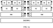
- FIG. 1a , FIG. 1b , and FIG. 1c show distribution of OFDMA RUs at system bandwidths of 20 MHz, 40 MHz, and 80 MHz, respectively.
- An arrow indicates a location of a leftover subcarrier (leftover tone) between RUs.
- a quantity of subcarriers corresponding to large-granularity RUs is equal to a sum of a quantity of subcarriers corresponding to a plurality of small-granularity RUs that can be included in the large-granularity RUs and a quantity of leftover subcarriers between small-granularity RUs.
- an OFDMA multi-user data packet may include RUs of a plurality of granularities, and an AP allocates one RU to one user.
- RUs that can be allocated include:
- HE-LTFs in two modes may be used for channel estimation.
- a subcarrier number (index) corresponding to an HE-LTF sequence in a 4x mode is the same as a tone plan of a data portion.
- every other tone is selected from a tone plan of a data portion, that is, a corresponding subcarrier number thereof is a subcarrier number corresponding to the HE-LTF sequence in the 2x mode.
- a corresponding subcarrier number thereof is a subcarrier number corresponding to the HE-LTF sequence in the 2x mode.
- data sequences that are two times those in the 2x mode are inserted in a same tone plan. Therefore, more data can be transmitted in the 4x mode.
- a downlink multi-user presentation protocol data unit (Presentation Protocol Data Unit, PPDU for short) sent by the AP is shown in FIG. 2a .
- An uplink multi-user PPDU sent by a STA is shown in FIG. 2b .
- an HE-SIG-A field is used to indicate a downlink STA transmission bandwidth
- an HE-SIG-B field is used to indicate a size and a location of an RU allocated by a STA that is scheduled in downlink, a STA ID corresponding to each scheduled STA, and other scheduling information such as a spatial flow number, and modulation and coding.
- the HE-SIG-A field or the HE-SIG-B field may indicate that a plurality of STAs align an HE-LTF length, that is, indicate a symbol quantity N.
- Solution 1 Masking-manner indication information used for second-time masking is pre-stored.
- a terminal obtains a pilot sequence
- first-time masking is performed on the pilot sequence based on a cyclic orthogonal matrix
- second-time masking is performed, based on the pre-stored masking-manner indication information, on the pilot sequence on which first-time masking has been performed.
- Solution 2 A pilot sequence on which two times of masking are performed is pre-stored.
- a terminal may obtain, based on information such as a size and a location of an allocated RU, the corresponding pilot sequence on which the two times of masking are performed.
- the two times of masking means that first-time masking is performed based on a cyclic orthogonal matrix and then second-time masking is performed, based on a pre-determined masking manner, on the pilot sequence on which first-time masking has been performed.
- masking-manner indication information used for second-time masking may be preset, where the masking-manner indication information may indicate a masking manner for the pilot sequence on which first-time masking has been performed.
- the masking-manner indication information may indicate whether original polarity of each piece of data in the pilot sequence is to be kept or is to be reversed, where one piece of data in the pilot sequence is one element in the sequence, and one element is corresponding to one data subcarrier.
- the masking-manner indication information may also indicate whether original polarity of each subsequence in the pilot sequence is to be kept or is to be reversed, where one subsequence includes a plurality of elements, that is, one subsequence is corresponding to a plurality of subcarriers.
- a block mask template may be preset, where the block mask template provides, in unit of a block, masking-manner indication information corresponding to each block, and one block is corresponding to one subsequence in the pilot sequence.
- masking may be performed on a corresponding subsequence based on a masking manner corresponding to each block, where masking manners of all elements in the subsequence are the same.
- a block size is fixed, for example, one block is corresponding to one subsequence of a length L, that is, a block length is L.
- a value of L may be set based on a requirement. For example, the value of L may be 2, 4, 6, 8, or the like.
- the preset block mask template may be obtained based on a method such as emulation. For example, if a block length is equal to L, all possible block mask templates are determined for a pilot sequence, so as to form a candidate block mask template set. First-time masking is performed on the pilot sequence based on the cyclic orthogonal matrix, and then second-time masking is performed, by using all block mask templates in the candidate block mask template set one by one, on the pilot sequence on which first-time masking has been performed, and PAPRs obtained by using different candidate block mask templates are measured. A candidate block mask template corresponding to a most reduced PAPR is obtained by comparing the PAPRs corresponding to the candidate block mask templates.
- the block mask template is stored in a STA to be used as a block mask template for second-time masking.
- a PAPR measured after second-time masking is performed by using a candidate block mask template may be compared with a PAPR measured after first-time masking is performed.
- the selected block mask template is a block mask template, among all candidate block mask templates, that can be used to obtain a most reduced PAPR and improve orthogonality.
- both a PAPR and orthogonality may be balanced based on a requirement.
- a value of a block length L of the block mask template may be set based on a requirement.
- a scale of a candidate block mask template set used in a process of selecting an appropriate block mask template through emulation is smaller, leading to lower calculation overheads and higher processing efficiency; and higher processing efficiency is achieved when second-time masking is performed, by using the selected block mask template, on the pilot sequence on which first-time masking has been performed.
- the value of L may be set based on a requirement, so as to achieve balance between the two cases.
- corresponding block mask templates may be set based on RUs with different sizes and locations. Further, if the system supports pilot sequences in a 2x mode and in a 4x mode, block mask templates may be set for RUs with different sizes and locations in different modes.
- MASK (-128:2:127) includes 32 pieces of block indication information, and each piece of block indication information is represented by "+" or "-".
- (-128:2:127) indicates that numbers of subcarriers corresponding to the mask are from -128 to 127, and the mask (namely, the block mask template) is used in the 2x mode.
- a value is selected from values corresponding to every two subcarriers in the pilot sequence, so as to obtain the pilot sequence in the 2x mode.
- Each block in the mask is corresponding to a subsequence of a length of 4 in the pilot sequence in the 2x mode.
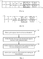
- FIG. 3 is a schematic diagram of a pilot sequence sending process according to an embodiment of this application.
- the process may be executed by a terminal (for example, a STA), and more specifically, may be executed by a transmitter in the terminal. As shown in the figure, the process may include the following steps.
- Step 301 Obtain a pilot sequence based on at least an allocated RU.
- An 802.11 ax system is used as an example.
- different system bandwidths are corresponding to different HE-LTF sequences
- different uplink MIMO sending modes (such as a 2x mode and a 4x mode) are corresponding to different HE-LTF sequences at a same bandwidth.
- different RU locations and sizes are corresponding to different HE-LTF sequences. Therefore, the STA may obtain a corresponding pilot sequence based on a system bandwidth, a size and a location of an RU allocated by an AP to the STA, an uplink MIMO sending mode, and the like.
- the system bandwidth may not be used as a basis to obtain the pilot sequence; if the uplink MIMO sending mode is single or fixed, the uplink MIMO sending mode may not be used as a basis to obtain the pilot sequence.
- Step 302 Perform first-time masking on the obtained pilot sequence based on a cyclic orthogonal matrix.
- the cyclic orthogonal matrix used in this step may be a P-matrix.
- the P-matrix is usually an 8x8 matrix.
- P 8 ⁇ 8 1 ⁇ 1 1 1 1 1 ⁇ 1 1 1 1 1 1 1 1 1 1 1 1 ⁇ 1 1 1 1 ⁇ 1 1 1 1 ⁇ 1 1 1 1 ⁇ 1 1 1 1 ⁇ 1 1 1 1 ⁇ 1 1 1 1 ⁇ 1 1 1 1 ⁇ 1 1 1 1 ⁇ 1 1 1 ⁇ 1 1 1 ⁇ 1 1 1 ⁇ 1 1 1 ⁇ 1 1 1 ⁇ 1 1 1 ⁇ 1 1 1 ⁇ 1 1 1 ⁇ 1 1 1 1 ⁇ 1 ⁇ 1 1 1 1 ⁇ 1 ⁇ 1 1 1 1 1 ⁇ 1 ⁇ 1 ⁇ 1 1 1 1 1 ⁇ 1 ⁇ 1 ⁇ 1 ⁇ 1 ⁇ 1 ⁇ 1 ⁇ 1 ⁇ 1 ⁇ 1 ⁇ 1 ⁇ 1 ⁇ 1 ⁇ 1 ⁇ 1 ⁇ 1 ⁇ 1 ⁇ 1 ⁇ 1 ⁇ 1 ⁇ 1
- Eight rows of sequences in the P-matrix are corresponding to eight encoded sequence flows, respectively, and a corresponding row of the matrix is used for masking each HE-LTF sequence flow.
- P1, P2, P3, P4, P5, P6, P7, and P8 are corresponding to the first to the eighth rows in the P-matrix, respectively.
- the P-matrix is used for mask processing based on a block length of 8.
- the first row of sequence in the P-matrix is used for masking a first flow
- the second row of sequence in the P-matrix is used for masking a second flow, and so on. That is, every eight pieces of data are used as one block, and masking is performed based on a row of sequence in the P-matrix, so as to ensure orthogonality.
- "1" indicates that original polarity is kept unchanged, and "-1" indicates that polarity is reversed. When a data length cannot be exactly divided by 8, remaining data is filled with 0 to ensure orthogonality.
- the cyclic orthogonal matrix used in this step may alternatively be a Chu-matrix.
- the Chu-matrix is usually an 8x8 matrix.
- each row of sequence in the Chu-matrix is obtained through cyclic shifting on a previous row of sequence. There is cyclic orthogonality between rows. PAPRs obtained after all rows are used for mask processing on the pilot sequence in a same manner are the same.
- cyclic orthogonal matrix used in the embodiment of this application is not limited to the P-matrix and Chu-matrix illustrated above. Cyclic orthogonal matrix in another form also falls within the protection scope of this application, provided that orthogonality of a masked sequence can be ensured.
- Step 303 Perform second-time masking on the pilot sequence on which first-time masking has been performed.
- a preset block mask template may be used for second-time masking on the pilot sequence on which first-time masking has been performed.
- the STA may obtain a corresponding block mask template based on a system bandwidth, a size and a location of an RU allocated by the AP to the STA, an uplink MIMO sending mode, and the like, and then the block mask template is used to perform second-time masking on the pilot sequence on which first-time masking has been performed.
- the system bandwidth is single or fixed, the system bandwidth may not be used as a basis to obtain the block mask template; if the uplink MIMO sending mode is single or fixed, the uplink MIMO sending mode may not be used as a basis to obtain the block mask template.
- the block mask template includes indication information of a masking manner corresponding to each of M blocks is used as an example.
- masking may be performed on a subsequence corresponding to each block in the pilot sequence on which first-time masking has been performed, to obtain the pilot sequence on which second-time masking has been performed.
- a masking manner corresponding to a block is keeping polarity unchanged or making polarity reversed. If one block is corresponding to one subsequence of a length N in the pilot sequence, MxN is greater than or equal to a length of the pilot sequence on which first-time masking has been performed, where both M and N are integers greater than 1.
- the preset masking manner or block mask template is obtained by using a method such as emulation, so that a PAPR of the pilot sequence on which second-time masking has been performed is less than a PAPR of the pilot sequence on which first-time masking has been performed, and further, higher orthogonality can be obtained.
- Step 304 Send the pilot sequence on which second-time masking has been performed.
- 802.11 ax is used as an example.
- the STA may add the pilot sequence on which second-time masking has been performed to an HE-LTF field corresponding to the STA in a PPDU. Then, signal modulation, resource mapping, and other processing may be performed according to the 802.11 ax protocol, and the pilot sequence is sent by using an antenna.
- the STA may multiply an identification code allocated by the AP to the STA by the pilot sequence on which second-time masking has been performed, where the identification code is used to identify a STA scheduled based on uplink MU-MIMO.
- the operation of multiplying the identification code allocated by the AP to the STA may alternatively be performed after the pilot sequence is obtained in step 301, or performed after the pilot sequence on which first-time masking has been performed is obtained in step 302.
- a system bandwidth is 20 MHz
- an uplink MI-MIMO sending mode is a 2x mode
- an RU allocated by the AP to the STA is an RU of a largest granularity (an RU corresponding to 242 contiguous subcarriers shown in FIG. 1a ).
- the uplink MI-MIMO sending mode is a 2x mode
- the HE-LTF sequence in the 2x mode may be obtained in the following manner: One element is obtained from every two elements in the HE-LTF sequence corresponding to the 242 contiguous subcarriers, to obtain the HE-LTF sequence in the 2x mode.
- step 302 first-time masking is performed on the obtained HE-LTF sequence by using the P-matrix
- MASK ⁇ 128 : 2 : 127 + , + , + , + , + , ⁇ , ⁇ , + , ⁇ , + , ⁇ , ⁇ , + , + ⁇ , ⁇ , + , + , + , + , + , + , + , + , + , + , + , + , + , + , + , + , + , + , + , , , , , ⁇ , ⁇ , + , ⁇
- step 302 first-time masking is performed on the obtained HE-LTF sequence by using a cyclic orthogonal matrix, that is, a Chu-matrix
- a system bandwidth is 40 MHz
- an uplink MI-MIMO sending mode is a 2x mode
- an RU allocated by the AP to the STA is an RU of a largest granularity (an RU corresponding to 484 contiguous subcarriers shown in FIG. 1b ).
- the uplink MI-MIMO sending mode is a 2x mode
- the HE-LTF sequence in the 2x mode may be obtained in the following manner: One element is obtained from every two elements in the HE-LTF sequence corresponding to the 484 contiguous subcarriers, to obtain the HE-LTF sequence in the 2x mode.
- step 302 first-time masking is performed on the obtained HE-LTF sequence by using the P-matrix
- original polarity of the subsequence may be kept unchanged, or polarity of the subsequence may be reversed.
- Specific processing may be performed according to an agreement reached in advance. This is because for uplink MU-MIMO transmission, if original polarity of HE-LTF sequences in these locations is kept unchanged or polarity of HE-LTF sequences in these locations is reversed, neither a subsequent signal processing process is affected, nor HE-LTF sequence based channel estimation and frequency offset detection are affected.
- step 302 first-time masking is performed on the obtained HE-LTF sequence by using the cyclic orthogonal matrix, that is, the Chu-matrix
- a system bandwidth is 80 MHz
- an uplink MI-MIMO sending mode is a 2x mode
- an RU allocated by the AP to the STA is an RU of a largest granularity (an RU corresponding to 996 contiguous subcarriers shown in FIG. 1c ).
- the STA first obtains an HE-LTF sequence based on the RU corresponding to the 996 contiguous subcarriers, and then one element is obtained from every two elements in the HE-LTF sequence based on the uplink MI-MIMO sending mode (the 2x mode), to form the following HE-LTF sequence:
- the uplink MI-MIMO sending mode is a 2x mode
- the HE-LTF sequence in the 2x mode may be obtained in the following manner: One element is obtained from every two elements in the HE-LTF sequence corresponding to the 996 contiguous subcarriers, to obtain the HE-LTF sequence in the 2x mode.
- step 302 first-time masking is performed on the obtained HE-LTF sequence by using the P-matrix
- MASK ⁇ 512 : 2 : 511 0 , ⁇ , ⁇ , ⁇ , ⁇ , + , + , + , ⁇ , + , + , + , + , + , + , ⁇ , ⁇ , + , + , + , + , ⁇ , + , + , + ⁇ , + , + ⁇ , + , + , + ⁇ , + , + , + ⁇ , + , + , + ⁇ , + , + , + ⁇ , + , + , + , + ⁇ , + , + , + , + , + ⁇ , + , + , + , + , ⁇ , + ,
- original polarity of the subsequence may be kept unchanged, or polarity of the subsequence may be reversed. Specific processing may be performed according to an agreement reached in advance.
- step 302 first-time masking is performed on the obtained HE-LTF sequence by using the cyclic orthogonal matrix, that is, the Chu-matrix
- MASK ⁇ 512 : 2 : 511 ⁇ , + , + , + , ⁇ , + , ⁇ , ⁇ , ⁇ , + , ⁇ , + , + , ⁇ , + , + ⁇ , + , + ⁇ , + , + , + , + , + , + , + , + , + , + , + , + , + , + , + , + , + , + , + , + , + , + , + , + , + , + , + , + , + , + , + , + , + , + , + , + , + ,
- a processing process in which first-time masking is performed on an HE-LTF sequence in a 2x mode by using the P-matrix or the Chu-matrix and then second-time masking is performed on the HE-LTF sequence by using different block lengths is provided.
- the block masking manner provided by the foregoing processing process is merely an example. In the embodiment of this application, another block masking manner may alternatively be used for second-time masking.
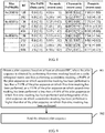
- the first column represents different bandwidths in the 2x mode; the second column represents quantities of RUs at different bandwidths in the 2x mode; the third column represents minimum PAPR values (target values) of data portions; the fourth column represents PAPR values of the HE-LTF sequence on which no mask processing is performed; the fifth column represents PAPR values of the HE-LTF sequence on which two times of masking (first-time masking is performed by using the P-matrix and then block masking is performed) are performed; the sixth column represents PAPR values of the HE-LTF sequence on which masking is performed merely based on the P sequence; values in brackets of the fourth, fifth, and sixth columns all are data obtained based on comparison with the target values in the third column.
- the first column represents different bandwidths in the 2x mode; the second column represents quantities of RUs at different bandwidths in the 2x mode; the third column represents minimum PAPR values (target values) of data portions; the fourth column represents PAPR values of the HE-LTF sequence on which no mask processing is performed; the fifth column represents PAPR values of the HE-LTF sequence on which two times of masking (first-time masking is performed by using the Chu-matrix and then block masking is performed) are performed; the sixth column represents PAPR values of the HE-LTF sequence on which masking is performed merely based on the Chu-matrix; values in brackets of the fourth, fifth, and sixth columns all are data obtained based on comparison with the target values in the third column.
- a system bandwidth is 20 MHz
- an uplink MI-MIMO sending mode is a 4x mode
- an RU allocated by the AP to the STA is an RU of a largest granularity (an RU corresponding to 242 contiguous subcarriers shown in FIG. 1a ).
- step 302 first-time masking is performed on the obtained HE-LTF sequence by using the P-matrix
- step 302 first-time masking is performed on the obtained HE-LTF sequence by using the P-matrix
- original polarity of the subsequence may be kept unchanged, or polarity of the subsequence may be reversed. Specific processing may be performed according to an agreement reached in advance.
- step 302 first-time masking is performed on the obtained HE-LTF sequence by using the Chu-matrix
- a system bandwidth is 40 MHz
- an uplink MI-MIMO sending mode is a 4x mode
- an RU allocated by the AP to the STA is an RU of a largest granularity (an RU corresponding to 484 contiguous subcarriers shown in FIG. 1b ).
- step 301 the STA obtains the following HE-LTF sequence based on the RU allocated by the AP to the STA:
- step 302 first-time masking is performed on the obtained HE-LTF sequence by using the P-matrix
- step 302 first-time masking is performed on the obtained HE-LTF sequence by using the P-matrix
- MASK ⁇ 256 : 255 x 1 , ⁇ , + , ⁇ , ⁇ , ⁇ , + , ⁇ , + , ⁇ , ⁇ , ⁇ , ⁇ , + , + , + , ⁇ , ⁇ , + , + , ⁇ , ⁇ , + , ⁇ , + , + ⁇ , + , + ⁇ , + , + ⁇ , + , + , + ⁇ , + , + , ⁇ , + , + , ⁇ , ⁇ , + , + , + , ⁇ , ⁇ , + , + , + , + ⁇ , ⁇ , + , + , + ⁇
- original polarity of the subsequence may be kept unchanged, or polarity of the subsequence may be reversed. Specific processing may be performed according to an agreement reached in advance.
- step 302 first-time masking is performed on the obtained HE-LTF sequence by using the Chu-matrix
- a system bandwidth is 80 MHz
- an uplink MI-MIMO sending mode is a 4x mode
- an RU allocated by the AP to the STA is an RU of a largest granularity (an RU corresponding to 996 contiguous subcarriers shown in FIG. 1c ).
- step 301 the STA obtains the following HE-LTF sequence based on the RU allocated by the AP to the STA:
- step 302 first-time masking is performed on the obtained HE-LTF sequence by using the P-matrix
- MASK ⁇ 512 : 511 0 , ⁇ , ⁇ , + , ⁇ , + , + , ⁇ , ⁇ , + , + , + , + , + , + , + , + , + , ⁇ , + , + , + ⁇ , + , + , ⁇ , + , ⁇ , + , ⁇ , + ⁇ , + ⁇ , ⁇ , + , ⁇ , + , ⁇ , + , ⁇ , ⁇ , + , + ⁇ , ⁇ , + , ⁇ , + , ⁇ , + , ⁇ , + , ⁇ , + , ⁇ , + , ⁇
- step 302 first-time masking is performed on the obtained HE-LTF sequence by using the P-matrix
- MASK ⁇ 512 : 511 x 1 , ⁇ , ⁇ , + , ⁇ , ⁇ , ⁇ , ⁇ , + , ⁇ , + , + , + , + , + , ⁇ , ⁇ , + , ⁇ , ⁇ , + , + ⁇ , + , + ⁇ , + , + ⁇ , + , + ⁇ , + , + ⁇ , + , + ⁇ , + , + , + ⁇ , ⁇ , + , + , + , + ⁇ , ⁇ , + , + , + , + , + , + , ⁇ , ⁇ , + , + , + , +
- original polarity of the subsequence may be kept unchanged, or polarity of the subsequence may be reversed. Specific processing may be performed according to an agreement reached in advance.
- step 302 first-time masking is performed on the obtained HE-LTF sequence by using the Chu-matrix
- MASK ⁇ 512 : 511 0 , ⁇ , + , + , + , ⁇ , + , ⁇ , ⁇ , ⁇ , + , ⁇ , ⁇ , ⁇ , ⁇ , + , ⁇ , ⁇ , ⁇ , + , + ⁇ , ⁇ , + , + , + , + , ⁇ , + , + , + , + , + , ⁇ , ⁇ , + , + , + , + , + , ⁇ , ⁇ , + , + , + , ⁇ , + , + , + , ⁇ , + , + , ⁇ , + , + , ⁇ , +
- a processing process in which first-time masking is performed on an HE-LTF sequence in a 4x mode by using the P-matrix or the Chu-matrix and then second-time masking is performed on the HE-LTF sequence by using different block lengths is provided.
- the block masking manner provided by the foregoing processing process is merely an example. In the embodiment of this application, another block masking manner may alternatively be used for second-time masking.
- the first column represents different bandwidths in the 4x mode; the second column represents quantities of RUs at different bandwidths in the 4x mode; the third column represents minimum PAPR values (target values) of data portions; the fourth column represents PAPR values of the HE-LTF sequence on which no mask processing is performed; the fifth column represents PAPR values of the HE-LTF sequence on which two times of masking (first-time masking is performed by using the P-matrix and then block masking is performed) are performed; the sixth column represents PAPR values of the HE-LTF sequence on which masking is performed merely based on the P sequence; values in brackets of the fourth, fifth, and sixth columns all are data obtained based on comparison with the target values in the third column.
- the first column represents different bandwidths in the 4x mode; the second column represents quantities of RUs at different bandwidths in the 4x mode; the third column represents minimum PAPR values (target values) of data portions; the fourth column represents PAPR values of the HE-LTF sequence on which no mask processing is performed; the fifth column represents PAPR values of the HE-LTF sequence on which two times of masking (first-time masking is performed by using the P-matrix and then block masking is performed) are performed; the sixth column represents PAPR values of the HE-LTF sequence on which masking is performed merely based on the P-matrix; values in brackets of the fourth, fifth, and sixth columns all are data obtained based on comparison with the target values in the third column.
- the first column represents different bandwidths in the 4x mode; the second column represents quantities of RUs at different bandwidths in the 4x mode; the third column represents minimum PAPR values (target values) of data portions; the fourth column represents PAPR values of the HE-LTF sequence on which no mask processing is performed; the fifth column represents PAPR values of the HE-LTF sequence on which masking is performed by using the Chu-matrix and then block masking is performed; the sixth column represents PAPR values of the HE-LTF sequence on which masking is performed merely based on the Chu_matrix; values in brackets of the fourth, fifth, and sixth columns all are data obtained based on comparison with the target values in the third column.
- two times of masking may be pre-performed on a pilot sequence (that is, first-time masking is performed on the pilot sequence based on a cyclic orthogonal matrix and then second-time masking is performed on the pilot sequence on which first-time masking has been performed), and then the pilot sequence on which the two times of masking are performed is stored.
- a STA only needs to obtain the pre-stored pilot sequence based on information such as an RU allocated to the STA, and sends the obtained pilot sequence.
- the pilot sequence obtained by the STA is a pilot sequence on which the two times of masking are performed, so that a PAPR of the pilot sequence is less than a PAPR of the pilot sequence on which first-time masking has been performed, and further, higher orthogonality can be obtained.
- two times of masking are performed on a pilot sequence corresponding to each RU, and the pilot sequence on which masking is performed is stored.
- a specific implementation method for performing the two times of masking on the pilot sequence is the same as the method for performing two times of masking described in solution 1. Details are not repeated herein.
- FIG. 9 is a schematic diagram of a pilot sequence sending process according to an embodiment of this application.
- the process may include the following steps.
- Step 901 Obtain a pilot sequence based on at least an allocated RU, where the pilot sequence is obtained by performing first-time masking based on a cyclic orthogonal matrix and then performing second-time masking, a PAPR of the pilot sequence on which second-time masking has been performed is less than a PAPR of the pilot sequence on which first-time masking has been performed, or a PAPR of the pilot sequence on which second-time masking has been performed is less than a PAPR of the pilot sequence on which first-time masking has been performed and orthogonality of the pilot sequence on which second-time masking has been performed is higher than that of the pilot sequence on which first-time masking has been performed.
- Step 902 Send the obtained pilot sequence.
- 802.11 ax is used as an example.
- a STA may add the obtained pilot sequence to an HE-LTF field corresponding to the STA in a PPDU.
- signal modulation, resource mapping, and other processing may be performed according to the 802.11 ax protocol, and the pilot sequence is sent by using an antenna.
- the STA may multiply an identification code allocated by the AP to the STA by the pilot sequence, where the identification code is used to identify a STA scheduled based on uplink MU-MIMO.
- an embodiment of this application further provides a resource indication processing apparatus, for example, an access point device (such as a STA).
- the apparatus may implement the pilot sequence sending process provided by the foregoing embodiments.
- a resource indication processing apparatus (not shown), where the apparatus is applied to a wireless local area network using an OFDMA technology, includes a processing unit, and is configured to execute the method in the foregoing implementation.
- the processing unit may be a general purpose processor, a digital signal processor, an application-specific integrated circuit, a field programmable gate array or another programmable logic device, a discrete gate or a transistor logic device, or a discrete hardware assembly, and may implement or execute the methods, steps, and logical block diagrams disclosed in the embodiments of the present invention.
- the general purpose processor may be a microprocessor, any conventional processor, or the like.
- the steps of the methods disclosed with reference to the embodiments of the present invention may be directly implemented by a hardware processor, or may be implemented by using a combination of hardware and software modules in the processor. It is easy to understand that the foregoing resource indication processing apparatus may be located at an access point or a station.
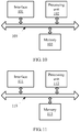
- FIG. 10 is a block diagram of an access point according to another embodiment of the present invention.
- the access point may implement the pilot sequence sending process provided by solution 1.
- the access point in FIG. 10 includes an interface 101, a processing unit 102, and a memory 103.
- the processing unit 102 controls an operation of the access point.
- the memory 103 may include a read-only memory and a random access memory, and provide an instruction and data to the processing unit 102.
- a part of the memory 103 may further include a non-volatile random access memory (NVRAM).
- Components of the access point are coupled together by using a bus system 109.
- the bus system 109 includes a power bus, a control bus, and a status signal bus. However, for clear description, various buses in the figure are denoted as the bus system 109.
- the frame sending methods disclosed in the foregoing embodiments of the present invention may be applied to the processing unit 102 or implemented by the processing unit 102.
- steps in the foregoing methods may be implemented by using an integrated logic circuit of hardware in the processing unit 102, or by using an instruction in a form of software.
- the processing unit 102 may be a general purpose processor, a digital signal processor, an application-specific integrated circuit, a field programmable gate array or another programmable logic device, a discrete gate or a transistor logic device, or a discrete hardware assembly, and may implement or execute the methods, steps, of the present invention.
- the general purpose processor may be a microprocessor, any conventional processor, or the like.
- the steps of the methods disclosed with reference to the embodiments of the present invention may be directly implemented by a hardware processor, or may be implemented by using a combination of hardware and software modules in the processor.
- the software module may be located in a random access memory, a flash memory, a read-only memory, a programmable read-only memory or an electrically erasable programmable memory, a register, or another mature storage medium in the art.
- the storage medium is located in the memory 103.
- the processing unit 102 reads information in the memory 103 and completes the steps of the foregoing methods in combination with hardware in the processing unit 102.
- FIG. 11 is a block diagram of a station according to another embodiment of the present invention.
- the station may implement the pilot sequence sending process provided by solution 2.
- the station in FIG. 11 includes an interface 111, a processing unit 112, and a memory 113.
- the processing unit 112 controls an operation of the station.
- the memory 113 may include a read-only memory and a random access memory, and provide an instruction and data to the processing unit 112.
- a part of the memory 113 may further include a non-volatile random access memory (NVRAM).
- Components of the station are coupled together by using a bus system 119.
- the bus system 119 includes a power bus, a control bus, and a status signal bus. However, for clear description, various buses in the figure are denoted as the bus system 119.
- the frame receiving methods disclosed in the foregoing embodiments of the present invention may be applied to the processing unit 112 or implemented by the processing unit 112.
- steps in the foregoing methods may be implemented by using an integrated logic circuit of hardware in the processing unit 112, or by using an instruction in a form of software.
- the processing unit 112 may be a general purpose processor, a digital signal processor, an application-specific integrated circuit, a field programmable gate array or another programmable logic device, a discrete gate or a transistor logic device, or a discrete hardware assembly, and may implement or execute the methods, steps, and logical block diagrams disclosed in the embodiments of the present invention.
- the general purpose processor may be a microprocessor, any conventional processor, or the like.
- the steps of the methods disclosed with reference to the embodiments of the present invention may be directly implemented by a hardware processor, or may be implemented by using a combination of hardware and software modules in the processor.
- the software module may be located in a random access memory, a flash memory, a read-only memory, a programmable read-only memory or an electrically erasable programmable memory, a register, or another mature storage medium in the art.
- the storage medium is located in the memory 113.
- the processing unit 112 reads information in the memory 113 and completes the steps of the foregoing methods in combination with hardware in the processing unit 112.
- the memory 113 stores the instruction that enables the processing unit 112 to perform the following operations: determining resource status information, where the resource status information indicates a busy/idle state of a sub-resource of a channel resource for data transmission between an access point and the station; and sending the resource status information to the access point, so that the access point allocates resources based on the resource status information.
- this application may be provided as a method, a system, or a computer program product. Therefore, this application may use a form of hardware only embodiments, software only embodiments, or embodiments with a combination of software and hardware. Moreover, this application may use a form of a computer program product that is implemented on one or more computer-usable storage media (including but not limited to a disk memory, a CD-ROM, an optical memory, and the like) that include computer usable program code.
- a computer-usable storage media including but not limited to a disk memory, a CD-ROM, an optical memory, and the like
- These computer program instructions may be provided for a general-purpose computer, a dedicated computer, an embedded processor, or a processor of any other programmable data processing device to generate a machine, so that the instructions executed by a computer or a processor of any other programmable data processing device generate an apparatus for implementing a specific function in one or more processes in the flowcharts and/or in one or more blocks in the block diagrams.
- These computer program instructions may be stored in a computer readable memory that can instruct the computer or any other programmable data processing device to work in a specific manner, so that the instructions stored in the computer readable memory generate an artifact that includes an instruction apparatus.
- the instruction apparatus implements a specific function in one or more processes in the flowcharts and/or in one or more blocks in the block diagrams.
- These computer program instructions may be loaded onto a computer or another programmable data processing device, so that a series of operations and steps are performed on the computer or the another programmable device, thereby generating computer-implemented processing. Therefore, the instructions executed on the computer or the another programmable device provide steps for implementing a specific function in one or more processes in the flowcharts and/or in one or more blocks in the block diagrams.
Landscapes
- Engineering & Computer Science (AREA)
- Signal Processing (AREA)
- Computer Networks & Wireless Communication (AREA)
- Physics & Mathematics (AREA)
- Spectroscopy & Molecular Physics (AREA)
- Power Engineering (AREA)
- Radio Transmission System (AREA)
- Mobile Radio Communication Systems (AREA)
Claims (8)
- Pilotsequenzsendeverfahren, Folgendes umfassend:Erhalten (301, 901) einer Pilotsequenz basierend auf wenigstens einer zugewiesenen Ressourceneinheit (resource unit- RU);Durchführen einer (302) erstmaligen Maskierung der Pilotsequenz basierend auf einer zyklischen orthogonalen Matrix;Durchführen einer (303) zweiten Maskierung auf der Pilotsequenz, an der eine erstmalige Maskierung durchgeführt wurde, wobei ein Spitzen-zu-Durchschnitt-Leistungsverhältnis (peak-to-average power ratio - PAPR) der Pilotsequenz, an der eine zweite Maskierung durchgeführt wurde, geringer als ein PAPR der Pilotsequenz ist, auf der die erstmalige Maskierung durchgeführt wurde, oder ein PAPR der Pilotsequenz, auf der die zweite Maskierung durchgeführt wurde, geringer als ein PAPR der Pilotsequenz ist, auf der die erstmalige Maskierung durchgeführt wurde, und die Orthogonalität der Pilotsequenz, auf der die zweite Maskierung durchgeführt wurde, höher als die der Pilotsequenz ist, auf der die erstmalige Maskierung durchgeführt wurde; undSenden (304, 902) der Pilotsequenz, auf der eine zweite Maskierung durchgeführt wurde;wobei das Durchführen der (303) zweiten Maskierung auf der Pilotsequenz, auf der eine erstmalige Maskierung durchgeführt wurde, Folgendes umfasst:Durchführen, basierend auf einer Maskierungsweise, die jedem der M-Blöcke entspricht, einer Maskierung auf einer Untersequenz, die jedem Block in der Pilotsequenz entspricht, auf der eine erstmalige Maskierung durchgeführt wurde, um die Pilotsequenz zu erhalten, auf der eine zweite Maskierung durchgeführt wurde, wobei ein Block einer Teilsequenz einer Länge N in der Pilotsequenz entspricht, MxN wenigstens eine Länge der Pilotsequenz ist, auf der die erstmalige Maskierung durchgeführt wurde, und sowohl M als auch N ganze Zahlen über 1 sind; undwobei vor dem Durchführen, basierend auf einer Maskierungsweise, die jedem der M-Blöcke entspricht, eine Teilsequenz maskiert wird, die jedem Block in der Pilotsequenz entspricht, auf der die erstmalige Maskierung durchgeführt wurde, ferner Folgendes umfassend:
Erhalten einer voreingestellten Blockmaskenschablone für die zweite Maskierung, basierend auf wenigstens der zugewiesenen RU, wobei die Blockmaskenschablone Anzeigeinformationen der Maskierungsweise umfasst, die jedem der M-Blöcken entspricht, wobei das Erhalten der voreingestellten Blockmaskenschablone ferner Folgendes umfasst:Bestimmen aller möglichen Blockmaskenschablonen für die Pilotsequenz;Messen und Vergleichen von PAPRs, die durch Verwenden der Blockmaskenschablonen erhalten wurden;Speichern der Blockmaskenschablone, die einem am meisten reduzierten PAPR entspricht, als voreingestellte Blockmaskenschablone. - Verfahren nach einem der Ansprüche 1, wobei eine Maskierungsweise, die einem Block entspricht, die Polarität unverändert lässt oder die Polarität umkehrt.
- Verfahren nach einem der Ansprüche 1 bis 2, wobei das Erhalten (301, 901) einer Pilotsequenz Folgendes umfasst:Erhalten der Pilotsequenz basierend auf der Größe und dem Ort der zugewiesenen RU; oderErhalten der Pilotsequenz basierend auf der Größe und dem Ort der zugewiesenen Ressourceneinheit (RU) und des Uplink-MU-MIMO-Sendemodus; oderErhalten der Pilotsequenz basierend auf der Systembandbreite, der Größe und dem Ort der zugewiesenen RU und dem Uplink-MU-MIMO-Sendemodus.
- Verfahren nach einem der Ansprüche 1 bis 3, vor dem Senden (304, 902) der Pilotsequenz, auf der eine zweite Maskierung durchgeführt wurde, ferner Folgendes umfassend:
Multiplizieren eines zugeordneten Identifikationscodes durch die Pilotsequenz, auf der eine zweite Maskierung durchgeführt wurde, wobei der Identifikationscode verwendet wird, um ein Endgerät zu identifizieren, basierend auf Uplink-MU-MIMO. - Pilotsequenzsendevorrichtung, Folgendes umfassend:ein Erhaltensmodul (102, 112), das konfiguriert ist, um eine Pilotsequenz zu erhalten;ein erstes Maskierungsmodul (102, 112), das konfiguriert ist, um basierend auf einer zyklischen orthogonalen Matrix eine erstmalige Maskierung der durch das Erhaltensmodul erhaltenen Pilotsequenz durchzuführen;ein zweites Maskierungsmodul (102, 112), das konfiguriert ist, um eine zweite Maskierung auf der Pilotsequenz durchzuführen, auf der eine erstmalige Maskierung durch das erste Maskierungsmodul durchgeführt wird, wobei ein Spitzen-zu-Durchschnitt-Leistungsverhältnis (PAPR) der Pilotsequenz, auf der die zweite Maskierung durchgeführt wurde, geringer als eine PAPR der Pilotsequenz ist, auf der die Maskierung der ersten Zeit durchgeführt wurde; undein Sendemodul, das konfiguriert ist, um die Pilotsequenz zu senden, auf der eine zweite Maskierung durch das zweite Maskierungsmodul durchgeführt wird;wobei das zweite Maskierungsmodul (102, 112) speziell für Folgendes konfiguriert ist:Durchführen, basierend auf einer Maskierungsweise, die jedem der M-Blöcke entspricht, der Maskierung auf einer Untersequenz, die jedem Block in der Pilotsequenz entspricht, auf der die erstmalige Maskierung durchgeführt wurde, um die Pilotsequenz zu erhalten, auf der eine zweite Maskierung durchgeführt wurde, wobei ein Block einer Teilsequenz einer Länge N in der Pilotsequenz entspricht, MxN wenigstens eine Länge der Pilotsequenz ist, auf der die erstmalige Maskierung durchgeführt wurde, und sowohl M als auch N ganze Zahlen über 1 sind;wobei das zweite Maskierungsmodul (102, 112) ferner für Folgendes konfiguriert ist:Durchführen, basierend auf einer Maskierungsweise, die jedem der M-Blöcke entspricht, der Maskierimg auf einer Untersequenz, die jedem Block in der Pilotsequenz entspricht, auf der die erstmalige Maskierung durchgeführt wurde, um die voreingestellte Blockmaskenvorlage für die zweite Maskierung zu erhalten, basierend auf wenigstens einer zugewiesenen RU, wobei die Blockmaskenvorlage Anzeigeinformationen der Maskierungsweise umfasst, die jedem der M Blöcke entsprechen;Bestimmen aller möglichen Blockmaskenschablonen für die Pilotsequenz;Messen und Vergleichen von PAPRs, die durch Verwenden der Blockmaskenschablonen erhalten wurden;Speichern der Blockmaskenschablone, die einem am meisten reduzierten PAPR entspricht, als voreingestellte Blockmaskenschablone.
- Vorrichtung nach einem der Ansprüche 5, wobei eine Maskierungsweise, die einem Block entspricht, die Polarität unverändert lässt oder die Polarität umkehrt.
- Vorrichtung nach einem der Ansprüche 5, wobei das Erhaltensmodul (102, 112) speziell für Folgendes konfiguriert ist:Erhalten der Pilotsequenz basierend auf der Größe und dem Ort der zugewiesenen RU; oderErhalten der Pilotsequenz basierend auf der Größe und dem Ort der zugewiesenen Ressourceneinheit (RU) und des Uplink-MU-MIMO-Sendemodus; oderErhalten der Pilotsequenz basierend auf der Systembandbreite, der Größe und dem Ort der zugewiesenen RU und dem Uplink-MU-MIMO-Sendemodus.
- Vorrichtung nach einem der Ansprüche 5, ferner Folgendes umfassend:
ein Verarbeitungsmodul (102, 112), das für Folgendes konfiguriert ist:
bevor die Pilotsequenz, auf der die zweite Maskierung durchgeführt wurde, gesendet wird, Multiplizieren eines zugewiesenen Identifizierungscodes mit der Pilotsequenz, auf der die zweite Maskierung durchgeführt wurde, wobei der Identifizierungscode verwendet wird, um ein Endgerät zu identifizieren, das basierend auf Uplink-MU-MIMO geplant ist.
Applications Claiming Priority (2)
| Application Number | Priority Date | Filing Date | Title |
|---|---|---|---|
| CN201610116067.0A CN107135178B (zh) | 2016-02-29 | 2016-02-29 | 一种导频序列发送方法及装置 |
| PCT/CN2017/074256 WO2017148304A1 (zh) | 2016-02-29 | 2017-02-21 | 一种导频序列发送方法及装置 |
Publications (3)
| Publication Number | Publication Date |
|---|---|
| EP3416342A1 EP3416342A1 (de) | 2018-12-19 |
| EP3416342A4 EP3416342A4 (de) | 2019-02-20 |
| EP3416342B1 true EP3416342B1 (de) | 2020-08-05 |
Family
ID=59721342
Family Applications (1)
| Application Number | Title | Priority Date | Filing Date |
|---|---|---|---|
| EP17759155.9A Active EP3416342B1 (de) | 2016-02-29 | 2017-02-21 | Pilotfrequenzsequenzsendeverfahren und -vorrichtung |
Country Status (4)
| Country | Link |
|---|---|
| US (1) | US10756865B2 (de) |
| EP (1) | EP3416342B1 (de) |
| CN (1) | CN107135178B (de) |
| WO (1) | WO2017148304A1 (de) |
Families Citing this family (3)
| Publication number | Priority date | Publication date | Assignee | Title |
|---|---|---|---|---|
| CN112702128B (zh) * | 2019-10-23 | 2023-05-12 | 中兴通讯股份有限公司 | 信道测量方法、第一设备、第二设备及计算机可读介质 |
| CN113938864B (zh) * | 2020-06-29 | 2025-12-12 | 华为技术有限公司 | 一种序列生成方法及相关设备 |
| CN117353760A (zh) * | 2022-02-21 | 2024-01-05 | 联发科技股份有限公司 | 通信设备以及无线通信方法 |
Family Cites Families (13)
| Publication number | Priority date | Publication date | Assignee | Title |
|---|---|---|---|---|
| US4843587A (en) * | 1987-12-10 | 1989-06-27 | General Dynamics Pomona Division | Processing system for performing matrix multiplication |
| US5483475A (en) * | 1993-09-15 | 1996-01-09 | Industrial Technology Research Institute | Fast pipelined 2-D discrete cosine transform architecture |
| US5933537A (en) * | 1996-07-29 | 1999-08-03 | Polaroid Corporation | Method and apparatus for conversion of frequency-coefficient matrices |
| KR101532821B1 (ko) * | 2010-04-02 | 2015-06-30 | 후지쯔 가부시끼가이샤 | Occ 생성을 위한 장치 및 방법과 occ 매핑을 위한 장치 및 방법 |
| US8982686B2 (en) * | 2010-06-07 | 2015-03-17 | Qualcomm Incorporated | Communication devices for generating and using a matrix-mapped sequence |
| WO2013066739A1 (en) | 2011-11-02 | 2013-05-10 | Marvell World Trade Ltd. | Method and apparatus for automatically detecting a physical layer (phy) mode of a data unit in a wireless local area network (wlan) |
| US20130322563A1 (en) * | 2012-06-04 | 2013-12-05 | Qualcomm Incorporated | Communication device, method, computer-program product and apparatus for transmitting a pilot sequence with a reduced peak-to-average power ratio contribution |
| US9065482B1 (en) * | 2013-03-13 | 2015-06-23 | Xilinx, Inc. | Circuit for forward error correction encoding of data blocks |
| WO2015073437A1 (en) | 2013-11-12 | 2015-05-21 | Huawei Technologies Co., Ltd. | System and method for high efficiency wireless local area network communications |
| US10117254B2 (en) * | 2015-07-31 | 2018-10-30 | Qualcomm Incorporated | Pilot sequences in data streams |
| US9998951B2 (en) * | 2015-08-05 | 2018-06-12 | Qualcomm Incorporated | Training sequence generation for wireless communication networks |
| US10123329B2 (en) * | 2015-10-07 | 2018-11-06 | Intel IP Corporation | Long training field in uplink multi-user multiple-input multiple-output communications |
| US9686757B1 (en) * | 2015-11-11 | 2017-06-20 | Newracom, Inc. | Peak to average power ratio (PAPR) reduction in a wireless network |
-
2016
- 2016-02-29 CN CN201610116067.0A patent/CN107135178B/zh active Active
-
2017
- 2017-02-21 EP EP17759155.9A patent/EP3416342B1/de active Active
- 2017-02-21 WO PCT/CN2017/074256 patent/WO2017148304A1/zh not_active Ceased
-
2018
- 2018-08-28 US US16/115,296 patent/US10756865B2/en active Active
Non-Patent Citations (1)
| Title |
|---|
| None * |
Also Published As
| Publication number | Publication date |
|---|---|
| US20180367276A1 (en) | 2018-12-20 |
| CN107135178B (zh) | 2020-01-17 |
| US10756865B2 (en) | 2020-08-25 |
| EP3416342A4 (de) | 2019-02-20 |
| EP3416342A1 (de) | 2018-12-19 |
| WO2017148304A1 (zh) | 2017-09-08 |
| CN107135178A (zh) | 2017-09-05 |
Similar Documents
| Publication | Publication Date | Title |
|---|---|---|
| EP4280554B1 (de) | Verfahren zur übertragung einer he-ltf-sequenz und vorrichtung | |
| US11784864B2 (en) | Physical layer protocol data unit transmission method and apparatus | |
| EP3611989B1 (de) | Verfahren und vorrichtung zur übertragung von informationen eines drahtlosen lokalen netzwerks | |
| CN101594215B (zh) | 控制信道单元数量确定方法及装置、控制信道管理方法 | |
| US11916710B2 (en) | Data transmission method and apparatus | |
| US20230309087A1 (en) | Methods and apparatuses for soliciting trigger-based physical layer protocol data unit transmission in wireless local area network | |
| US10756865B2 (en) | Pilot sequence sending method and apparatus | |
| AU2021413193B2 (en) | Method and apparatus for reducing a peak to average power ratio in the transmission of physical layer protocol data units | |
| US10326571B2 (en) | Resource allocation instruction method and device |
Legal Events
| Date | Code | Title | Description |
|---|---|---|---|
| STAA | Information on the status of an ep patent application or granted ep patent |
Free format text: STATUS: THE INTERNATIONAL PUBLICATION HAS BEEN MADE |
|
| PUAI | Public reference made under article 153(3) epc to a published international application that has entered the european phase |
Free format text: ORIGINAL CODE: 0009012 |
|
| STAA | Information on the status of an ep patent application or granted ep patent |
Free format text: STATUS: REQUEST FOR EXAMINATION WAS MADE |
|
| 17P | Request for examination filed |
Effective date: 20180911 |
|
| AK | Designated contracting states |
Kind code of ref document: A1 Designated state(s): AL AT BE BG CH CY CZ DE DK EE ES FI FR GB GR HR HU IE IS IT LI LT LU LV MC MK MT NL NO PL PT RO RS SE SI SK SM TR |
|
| AX | Request for extension of the european patent |
Extension state: BA ME |
|
| A4 | Supplementary search report drawn up and despatched |
Effective date: 20190121 |
|
| RIC1 | Information provided on ipc code assigned before grant |
Ipc: H04L 27/26 20060101AFI20190115BHEP Ipc: H04L 25/03 20060101ALI20190115BHEP |
|
| DAV | Request for validation of the european patent (deleted) | ||
| DAX | Request for extension of the european patent (deleted) | ||
| GRAP | Despatch of communication of intention to grant a patent |
Free format text: ORIGINAL CODE: EPIDOSNIGR1 |
|
| STAA | Information on the status of an ep patent application or granted ep patent |
Free format text: STATUS: GRANT OF PATENT IS INTENDED |
|
| INTG | Intention to grant announced |
Effective date: 20200225 |
|
| GRAS | Grant fee paid |
Free format text: ORIGINAL CODE: EPIDOSNIGR3 |
|
| GRAA | (expected) grant |
Free format text: ORIGINAL CODE: 0009210 |
|
| STAA | Information on the status of an ep patent application or granted ep patent |
Free format text: STATUS: THE PATENT HAS BEEN GRANTED |
|
| AK | Designated contracting states |
Kind code of ref document: B1 Designated state(s): AL AT BE BG CH CY CZ DE DK EE ES FI FR GB GR HR HU IE IS IT LI LT LU LV MC MK MT NL NO PL PT RO RS SE SI SK SM TR |
|
| REG | Reference to a national code |
Ref country code: GB Ref legal event code: FG4D |
|
| REG | Reference to a national code |
Ref country code: CH Ref legal event code: EP |
|
| REG | Reference to a national code |
Ref country code: AT Ref legal event code: REF Ref document number: 1300309 Country of ref document: AT Kind code of ref document: T Effective date: 20200815 |
|
| REG | Reference to a national code |
Ref country code: DE Ref legal event code: R096 Ref document number: 602017021183 Country of ref document: DE |
|
| REG | Reference to a national code |
Ref country code: IE Ref legal event code: FG4D |
|
| REG | Reference to a national code |
Ref country code: LT Ref legal event code: MG4D |
|
| REG | Reference to a national code |
Ref country code: NL Ref legal event code: MP Effective date: 20200805 |
|
| REG | Reference to a national code |
Ref country code: AT Ref legal event code: MK05 Ref document number: 1300309 Country of ref document: AT Kind code of ref document: T Effective date: 20200805 |
|
| PG25 | Lapsed in a contracting state [announced via postgrant information from national office to epo] |
Ref country code: BG Free format text: LAPSE BECAUSE OF FAILURE TO SUBMIT A TRANSLATION OF THE DESCRIPTION OR TO PAY THE FEE WITHIN THE PRESCRIBED TIME-LIMIT Effective date: 20201105 Ref country code: LT Free format text: LAPSE BECAUSE OF FAILURE TO SUBMIT A TRANSLATION OF THE DESCRIPTION OR TO PAY THE FEE WITHIN THE PRESCRIBED TIME-LIMIT Effective date: 20200805 Ref country code: AT Free format text: LAPSE BECAUSE OF FAILURE TO SUBMIT A TRANSLATION OF THE DESCRIPTION OR TO PAY THE FEE WITHIN THE PRESCRIBED TIME-LIMIT Effective date: 20200805 Ref country code: HR Free format text: LAPSE BECAUSE OF FAILURE TO SUBMIT A TRANSLATION OF THE DESCRIPTION OR TO PAY THE FEE WITHIN THE PRESCRIBED TIME-LIMIT Effective date: 20200805 Ref country code: FI Free format text: LAPSE BECAUSE OF FAILURE TO SUBMIT A TRANSLATION OF THE DESCRIPTION OR TO PAY THE FEE WITHIN THE PRESCRIBED TIME-LIMIT Effective date: 20200805 Ref country code: SE Free format text: LAPSE BECAUSE OF FAILURE TO SUBMIT A TRANSLATION OF THE DESCRIPTION OR TO PAY THE FEE WITHIN THE PRESCRIBED TIME-LIMIT Effective date: 20200805 Ref country code: GR Free format text: LAPSE BECAUSE OF FAILURE TO SUBMIT A TRANSLATION OF THE DESCRIPTION OR TO PAY THE FEE WITHIN THE PRESCRIBED TIME-LIMIT Effective date: 20201106 Ref country code: NO Free format text: LAPSE BECAUSE OF FAILURE TO SUBMIT A TRANSLATION OF THE DESCRIPTION OR TO PAY THE FEE WITHIN THE PRESCRIBED TIME-LIMIT Effective date: 20201105 Ref country code: ES Free format text: LAPSE BECAUSE OF FAILURE TO SUBMIT A TRANSLATION OF THE DESCRIPTION OR TO PAY THE FEE WITHIN THE PRESCRIBED TIME-LIMIT Effective date: 20200805 Ref country code: PT Free format text: LAPSE BECAUSE OF FAILURE TO SUBMIT A TRANSLATION OF THE DESCRIPTION OR TO PAY THE FEE WITHIN THE PRESCRIBED TIME-LIMIT Effective date: 20201207 |
|
| PG25 | Lapsed in a contracting state [announced via postgrant information from national office to epo] |
Ref country code: IS Free format text: LAPSE BECAUSE OF FAILURE TO SUBMIT A TRANSLATION OF THE DESCRIPTION OR TO PAY THE FEE WITHIN THE PRESCRIBED TIME-LIMIT Effective date: 20201205 Ref country code: RS Free format text: LAPSE BECAUSE OF FAILURE TO SUBMIT A TRANSLATION OF THE DESCRIPTION OR TO PAY THE FEE WITHIN THE PRESCRIBED TIME-LIMIT Effective date: 20200805 Ref country code: LV Free format text: LAPSE BECAUSE OF FAILURE TO SUBMIT A TRANSLATION OF THE DESCRIPTION OR TO PAY THE FEE WITHIN THE PRESCRIBED TIME-LIMIT Effective date: 20200805 Ref country code: PL Free format text: LAPSE BECAUSE OF FAILURE TO SUBMIT A TRANSLATION OF THE DESCRIPTION OR TO PAY THE FEE WITHIN THE PRESCRIBED TIME-LIMIT Effective date: 20200805 Ref country code: NL Free format text: LAPSE BECAUSE OF FAILURE TO SUBMIT A TRANSLATION OF THE DESCRIPTION OR TO PAY THE FEE WITHIN THE PRESCRIBED TIME-LIMIT Effective date: 20200805 |
|
| PG25 | Lapsed in a contracting state [announced via postgrant information from national office to epo] |
Ref country code: RO Free format text: LAPSE BECAUSE OF FAILURE TO SUBMIT A TRANSLATION OF THE DESCRIPTION OR TO PAY THE FEE WITHIN THE PRESCRIBED TIME-LIMIT Effective date: 20200805 Ref country code: CZ Free format text: LAPSE BECAUSE OF FAILURE TO SUBMIT A TRANSLATION OF THE DESCRIPTION OR TO PAY THE FEE WITHIN THE PRESCRIBED TIME-LIMIT Effective date: 20200805 Ref country code: DK Free format text: LAPSE BECAUSE OF FAILURE TO SUBMIT A TRANSLATION OF THE DESCRIPTION OR TO PAY THE FEE WITHIN THE PRESCRIBED TIME-LIMIT Effective date: 20200805 Ref country code: EE Free format text: LAPSE BECAUSE OF FAILURE TO SUBMIT A TRANSLATION OF THE DESCRIPTION OR TO PAY THE FEE WITHIN THE PRESCRIBED TIME-LIMIT Effective date: 20200805 Ref country code: SM Free format text: LAPSE BECAUSE OF FAILURE TO SUBMIT A TRANSLATION OF THE DESCRIPTION OR TO PAY THE FEE WITHIN THE PRESCRIBED TIME-LIMIT Effective date: 20200805 |
|
| REG | Reference to a national code |
Ref country code: DE Ref legal event code: R097 Ref document number: 602017021183 Country of ref document: DE |
|
| PG25 | Lapsed in a contracting state [announced via postgrant information from national office to epo] |
Ref country code: AL Free format text: LAPSE BECAUSE OF FAILURE TO SUBMIT A TRANSLATION OF THE DESCRIPTION OR TO PAY THE FEE WITHIN THE PRESCRIBED TIME-LIMIT Effective date: 20200805 |
|
| PLBE | No opposition filed within time limit |
Free format text: ORIGINAL CODE: 0009261 |
|
| STAA | Information on the status of an ep patent application or granted ep patent |
Free format text: STATUS: NO OPPOSITION FILED WITHIN TIME LIMIT |
|
| PG25 | Lapsed in a contracting state [announced via postgrant information from national office to epo] |
Ref country code: SK Free format text: LAPSE BECAUSE OF FAILURE TO SUBMIT A TRANSLATION OF THE DESCRIPTION OR TO PAY THE FEE WITHIN THE PRESCRIBED TIME-LIMIT Effective date: 20200805 |
|
| 26N | No opposition filed |
Effective date: 20210507 |
|
| PG25 | Lapsed in a contracting state [announced via postgrant information from national office to epo] |
Ref country code: IT Free format text: LAPSE BECAUSE OF FAILURE TO SUBMIT A TRANSLATION OF THE DESCRIPTION OR TO PAY THE FEE WITHIN THE PRESCRIBED TIME-LIMIT Effective date: 20200805 |
|
| PG25 | Lapsed in a contracting state [announced via postgrant information from national office to epo] |
Ref country code: SI Free format text: LAPSE BECAUSE OF FAILURE TO SUBMIT A TRANSLATION OF THE DESCRIPTION OR TO PAY THE FEE WITHIN THE PRESCRIBED TIME-LIMIT Effective date: 20200805 |
|
| PG25 | Lapsed in a contracting state [announced via postgrant information from national office to epo] |
Ref country code: MC Free format text: LAPSE BECAUSE OF FAILURE TO SUBMIT A TRANSLATION OF THE DESCRIPTION OR TO PAY THE FEE WITHIN THE PRESCRIBED TIME-LIMIT Effective date: 20200805 |
|
| GBPC | Gb: european patent ceased through non-payment of renewal fee |
Effective date: 20210221 |
|
| REG | Reference to a national code |
Ref country code: BE Ref legal event code: MM Effective date: 20210228 |
|
| PG25 | Lapsed in a contracting state [announced via postgrant information from national office to epo] |
Ref country code: CH Free format text: LAPSE BECAUSE OF NON-PAYMENT OF DUE FEES Effective date: 20210228 Ref country code: LI Free format text: LAPSE BECAUSE OF NON-PAYMENT OF DUE FEES Effective date: 20210228 Ref country code: LU Free format text: LAPSE BECAUSE OF NON-PAYMENT OF DUE FEES Effective date: 20210221 |
|
| PG25 | Lapsed in a contracting state [announced via postgrant information from national office to epo] |
Ref country code: GB Free format text: LAPSE BECAUSE OF NON-PAYMENT OF DUE FEES Effective date: 20210221 Ref country code: IE Free format text: LAPSE BECAUSE OF NON-PAYMENT OF DUE FEES Effective date: 20210221 Ref country code: FR Free format text: LAPSE BECAUSE OF NON-PAYMENT OF DUE FEES Effective date: 20210228 |
|
| PG25 | Lapsed in a contracting state [announced via postgrant information from national office to epo] |
Ref country code: BE Free format text: LAPSE BECAUSE OF NON-PAYMENT OF DUE FEES Effective date: 20210228 |
|
| PG25 | Lapsed in a contracting state [announced via postgrant information from national office to epo] |
Ref country code: CY Free format text: LAPSE BECAUSE OF FAILURE TO SUBMIT A TRANSLATION OF THE DESCRIPTION OR TO PAY THE FEE WITHIN THE PRESCRIBED TIME-LIMIT Effective date: 20200805 |
|
| PG25 | Lapsed in a contracting state [announced via postgrant information from national office to epo] |
Ref country code: HU Free format text: LAPSE BECAUSE OF FAILURE TO SUBMIT A TRANSLATION OF THE DESCRIPTION OR TO PAY THE FEE WITHIN THE PRESCRIBED TIME-LIMIT; INVALID AB INITIO Effective date: 20170221 |
|
| PG25 | Lapsed in a contracting state [announced via postgrant information from national office to epo] |
Ref country code: MK Free format text: LAPSE BECAUSE OF FAILURE TO SUBMIT A TRANSLATION OF THE DESCRIPTION OR TO PAY THE FEE WITHIN THE PRESCRIBED TIME-LIMIT Effective date: 20200805 |
|
| PG25 | Lapsed in a contracting state [announced via postgrant information from national office to epo] |
Ref country code: TR Free format text: LAPSE BECAUSE OF FAILURE TO SUBMIT A TRANSLATION OF THE DESCRIPTION OR TO PAY THE FEE WITHIN THE PRESCRIBED TIME-LIMIT Effective date: 20200805 |
|
| PG25 | Lapsed in a contracting state [announced via postgrant information from national office to epo] |
Ref country code: MT Free format text: LAPSE BECAUSE OF FAILURE TO SUBMIT A TRANSLATION OF THE DESCRIPTION OR TO PAY THE FEE WITHIN THE PRESCRIBED TIME-LIMIT Effective date: 20200805 |
|
| PGFP | Annual fee paid to national office [announced via postgrant information from national office to epo] |
Ref country code: DE Payment date: 20251230 Year of fee payment: 10 |