EP3416332A1 - Quantum communication device, quantum communication system and quantum communication method - Google Patents
Quantum communication device, quantum communication system and quantum communication method Download PDFInfo
- Publication number
- EP3416332A1 EP3416332A1 EP18154870.2A EP18154870A EP3416332A1 EP 3416332 A1 EP3416332 A1 EP 3416332A1 EP 18154870 A EP18154870 A EP 18154870A EP 3416332 A1 EP3416332 A1 EP 3416332A1
- Authority
- EP
- European Patent Office
- Prior art keywords
- retransmission
- key data
- data
- error correction
- corrected
- Prior art date
- Legal status (The legal status is an assumption and is not a legal conclusion. Google has not performed a legal analysis and makes no representation as to the accuracy of the status listed.)
- Granted
Links
Images



Classifications
-
- H—ELECTRICITY
- H04—ELECTRIC COMMUNICATION TECHNIQUE
- H04L—TRANSMISSION OF DIGITAL INFORMATION, e.g. TELEGRAPHIC COMMUNICATION
- H04L9/00—Cryptographic mechanisms or cryptographic arrangements for secret or secure communications; Network security protocols
- H04L9/08—Key distribution or management, e.g. generation, sharing or updating, of cryptographic keys or passwords
- H04L9/0816—Key establishment, i.e. cryptographic processes or cryptographic protocols whereby a shared secret becomes available to two or more parties, for subsequent use
- H04L9/0852—Quantum cryptography
- H04L9/0858—Details about key distillation or coding, e.g. reconciliation, error correction, privacy amplification, polarisation coding or phase coding
-
- H—ELECTRICITY
- H04—ELECTRIC COMMUNICATION TECHNIQUE
- H04B—TRANSMISSION
- H04B10/00—Transmission systems employing electromagnetic waves other than radio-waves, e.g. infrared, visible or ultraviolet light, or employing corpuscular radiation, e.g. quantum communication
- H04B10/70—Photonic quantum communication
-
- H—ELECTRICITY
- H04—ELECTRIC COMMUNICATION TECHNIQUE
- H04L—TRANSMISSION OF DIGITAL INFORMATION, e.g. TELEGRAPHIC COMMUNICATION
- H04L1/00—Arrangements for detecting or preventing errors in the information received
- H04L1/004—Arrangements for detecting or preventing errors in the information received by using forward error control
- H04L1/0056—Systems characterized by the type of code used
- H04L1/0057—Block codes
Definitions
- the present disclosure relates to a quantum communication device, a quantum communication system, and a quantum communication method.
- Quantum cryptography has been introduced in communication technology as an encryption scheme that is unbreakable even if computers have enough computing power, and many efforts have been made for its practical implementation.
- One of the efforts to practically implement the quantum cryptography in the communication technology is, for example, to study error correction technologies, and various types of error correction technologies have been developed.
- LDPC low-density parity-check
- a quantum communication device includes a corrector and a retransmission controller.
- the corrector is configured to generate corrected key data by performing error correction on received key data received from a transmitting device through a quantum channel.
- the retransmission controller is configured to transmit a retransmission request including retransmission target address information to the transmitting device through a control channel when a retransmission request condition is satisfied, and receive retransmission key data corresponding to the retransmission target address information from the transmitting device through the control channel. After receiving the retransmission key data, the corrector replaces corrected key data corresponding to the retransmission target address information with the retransmission key data.
- Described first is a first arrangement.
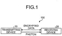
- FIG. 1 is a diagram illustrating an example device configuration of a quantum communication system 100 according to the first arrangement.
- the quantum communication system 100 according to the first arrangement includes two quantum communication devices (a transmitting device 10 and a receiver 20).
- the transmitting device 10 sequentially transmits photons indicating quantum bits to the receiver 20.
- the device that transmits photons is referred to as the transmitting device 10 in the first arrangement, but the transmitting device 10 may include a function of receiving photons.
- the receiver 20 may include a function of transmitting photons.
- the transmitting device 10 and the receiver 20 transmit and receive encrypted data using quantum key data.
- the method of generating quantum key data will be described in detail below with reference to FIG. 2 .
- the transmitting device 10 and the receiver 20 are connected with each other through a classical channel 2.
- the classical channel 2 is a control channel through which control information for generating quantum key data 105 (208) is transmitted and received.
- the control information includes an LDPC parameter 203, syndrome data 103, a retransmission request 206, and retransmission key data 104.
- the classical channel 2 may be a wired channel or a wireless channel, and may be implemented by both wired and wireless channels.
- the receiver 20 includes a receiver 21, a sifting processor 22, a determiner 23, a first corrector 24-1, a second corrector 24-2, a retransmission controller 25, and a privacy amplifier 26.
- the receiver 21 receives the transmission photon data 101 from the transmitter 11 through the quantum channel 1, thereby acquiring received photon data 201.
- the sifting processor 12 in the transmitting device 10 performs the sifting process on the transmission photon data 101 and acquires sifted key data 102.
- the sifting processor 12 inputs the sifted key data 102 to the generator 13 and to the privacy amplifier 15.
- the retransmitter 14 receives a retransmission request 206 from the receiver 20, the sifting processor 12 inputs data, out of the sifted key data 102, specified by the retransmission request 206 to the retransmitter 14.
- the determiner 23 in the receiver 20 determines an LDPC parameter 203 for use in error correction on the sifted key data 202.
- the LDPC parameter 203 may be determined by any method.
- the determiner 23 determines the LDPC parameter 203 by using, for example, an error rate of the previously received sifted key data 202 computed in the previous error correction.
- the determiner 23 transmits the LDPC parameter 203 to the generator 13 in the transmitting device 10 through the classical channel 2.
- the generator 13 in the transmitting device 10 receives the LDPC parameter 203 from the determiner 23 in the receiver 20 and receives the sifted key data 102 from the sifting processor 12.
- the generator 13 generates syndrome data 103 from the sifted key data 102 by using the LDPC parameter 203.
- the generator 13 transmits the syndrome data 103 to the first corrector 24-1 in the receiver 20 through the classical channel 2.
- the first corrector 24-1 in the receiver 20 receives the syndrome data 103 from the generator 13 in the transmitting device 10, receives the LDPC parameter 203 from the determiner 23, and receives the sifted key data 202 from the sifting processor 22.
- the first corrector 24-1 divides the sifted key data 202 into one or more error correction blocks and performs error correction on each error correction block.
- the first corrector 24-1 is implemented by, for example, an LDPC decoder.
- the first corrector 24-1 uses the syndrome data 103 and the LDPC parameter 203 to perform error correction on the sifted key data 202 (one or more error correction blocks), thereby generating first corrected key data 204 and retransmission control information 205.
- the first corrected key data 204 is binary data converted from a posterior value (analog value) of the sifted key data 202.
- the posterior value is computed upon execution of error correction (LDPC decoding).
- the posterior value is a log-likelihood ratio between a posterior probability that the data included in the sifted key data 202 is 1 and a posterior probability that the data included in the sifted key data 202 is 0, as a result of LDPC decoding.
- the posterior value is positive, the probability that the data is 1 is higher, whereas when the posteriori value is negative, the probability that the data is 0 is higher.
- the first corrector 24-1 sets the data corresponding to the posterior value to be 1, and when the posterior value is smaller than zero, the first corrector 24-1 sets the data corresponding to the posterior value to be 0, and generates the first corrected key data 204 from the sifted key data 202.
- the success/failure information indicates success or failure in error correction for each error correction block. For example, the success/failure information indicates success when it is 1, and indicates failure when it is 0.
- the error rate indicates the error rate of the sifted key data 202.
- the error rate of the sifted key data 202 is computed by comparing the first corrected key data 204 with the sifted key data 202 when the error correction on the one or more error correction blocks is successfully performed.
- the first corrector 24-1 inputs the first corrected key data 204 and the retransmission control information 205 to the retransmission controller 25.
- the retransmission controller 25 transmits the retransmission request 206 to the transmitting device 10 through the classical channel 2.
- the retransmitter 14 in the transmitting device 10 Upon reception of the retransmission request 206 from the retransmission controller 25 in the receiver 20, the retransmitter 14 in the transmitting device 10 acquires data specified by the retransmission target address information included in the retransmission request 206 from the sifted key data 102 and transmits the data to the retransmission controller 25 as retransmission key data 104.
- the retransmission controller 25 Upon reception of the retransmission key data 104 from the transmitting device 10 through the classical channel 2, the retransmission controller 25 inputs the retransmission key data 104 and the first corrected key data 204 to the second corrector 24-2.
- the second corrector 24-2 Upon reception of the retransmission key data 104 and the first corrected key data 204 from the retransmission controller 25, the second corrector 24-2 replaces data (error correction blocks in the first arrangement) corresponding to the retransmission target address information with the retransmission key data 104, thereby correcting the first corrected key data 204.
- the second corrector 24-2 inputs second corrected key data 207, which is generated by correcting the first corrected key data 204, to the privacy amplifier 26.
- FIG. 2 illustrates the first corrector 24-1 and the second corrector 24-2 as units for performing error correction
- the first corrector 24-1 and the second corrector 24-2 may be implemented by a single corrector.
- the privacy amplifier 26 Upon reception of the first corrected key data 204 from the retransmission controller 25, the privacy amplifier 26 performs privacy amplification on the first corrected key data 204 and generates quantum key data 208. In the same manner, upon reception of the second corrected key data 207 from the second corrector 24-2, the privacy amplifier 26 performs privacy amplification on the second corrected key data 207 and generates the quantum key data 208.
- the privacy amplification is a process of amplifying privacy in generating the quantum key data 208 by compressing the first corrected key data 204 or the second corrected key data 207.
- FIG. 3 is a flowchart illustrating an example retransmission control process according to the first arrangement.
- the retransmission controller 25 determines whether the retransmission request condition is satisfied (Step S1). Details of the retransmission request condition will be described later.
- Step S3 If all the error correction blocks have been successfully error corrected (Yes at Step S2), the retransmission controller 25 inputs the first corrected key data 204 to the privacy amplifier 26 (Step S3).
- the retransmission controller 25 transmits the retransmission request 206 to the transmitting device 10 through the classical channel 2 (Step S4).
- the retransmission controller 25 receives the retransmission key data 104 from the transmitting device 10 through the classical channel 2 (Step S5).
- the second corrector 24-2 replaces data of unsuccessfully error corrected blocks included in the first corrected key data 204 with the retransmission key data 104 to generate second corrected key data 207 (Step S6).
- the second corrector 24-2 inputs the second corrected key data 207 to the privacy amplifier 26 (Step S7).
- Condition (1) There is an error correction block that has been unsuccessfully error corrected.
- Condition (2) The sum of data lengths of the retransmission key data 104 is smaller than a certain value.
- the second corrector 24-2 replaces data of unsuccessfully error corrected blocks included in the first corrected key data 204 with the retransmission key data 104 and generates the second corrected key data 207, and the second corrected key data 207 is transmitted to the privacy amplifier 26.
- the retransmission key data 104 is transmitted through the classical channel 2, and thus the retransmission key data 104 is publicized in a common network.
- the privacy amplifier 26 increases the compression rate in the privacy amplification in accordance with the data length of the retransmission key data 104, thereby ensuring privacy of the quantum key data 208.
- Condition (2) relates to the size of data publicly transmitted in the classical channel 2 in executing the error correction and to a compression rate in the privacy amplification.
- the syndrome data 103 and the retransmission key data 104 are transmitted through the classical channel 2, and thus the syndrome data 103 and the retransmission key data 104 are publicized.
- the compression rate in the privacy amplification increases as the amount of data publicly transmitted is larger, and when the amount of data equates to a certain value T or greater, the compression rate will be zero or below zero.
- T the data length of public data with which the compression rate in privacy amplification will be zero
- S the syndrome length in error correction
- the certain value T is expressed as L - S.
- the data length L of the public data is determined in accordance with the error rate of the sifted key data 202.
- the data length of the retransmission key data 104 is a sum of data lengths of all the data of the unsuccessfully error corrected blocks.
- the retransmission controller 25 performs the retransmission process, whereas when the sum is the certain value T or greater, the retransmission controller 25 does not perform the retransmission process.
- Condition (2) can prevent the retransmission controller 25 from performing useless retransmission processes, thereby increasing the generation rate of the quantum key data 208.
- the data length L of the public data will be large.
- the compression rate in the privacy amplification will be zero or below zero, which will make the retransmission process useless, and thus, the retransmission controller 25 does not perform the retransmission process.
- Equation (1) H ⁇ PE A
- the first term on the right-hand side of Equation (1) indicates to which extent the eavesdropper eavesdrops on the transmission photon data 101 transmitted from the transmitter 11. When the first term on the right-hand side of Equation (1) is zero, it indicates that the eavesdropper eavesdrops on all the transmission photon data 101. When the first term on the right-hand side of Equation (1) is one, it indicates that the eavesdropper eavesdrops on no transmission photon data 101.
- the first term on the right-hand side of Equation (1) is computed based on, for example, an error rate of the sifted key data 202, and is closer to zero as the error rate increases.
- leak EC in Equation (1) accounts for the amount of data publicly transmitted through the classical channel 2 during error correction.
- the syndrome data 103 and the retransmission key data 104 are publicly transmitted through the classical channel 2.
- the amount of leak EC increases as the sum of the data length of the syndrome data 103 and the data length of the retransmission key data 104 increases, which results in a smaller compression rate r.
- Equation (1) ⁇ represents data indicating the finite length effect of the quantum key data 208.
- An error rate Q of the sifted key data 202 can be obtained by comparing the error correction blocks that are successfully error corrected with data corresponding to these error correction blocks in the sifted key data 202. Once the error rate Q of the sifted key data is obtained, the value of leak EC and the data length L with which the compression rate r will be zero can be obtained from Equation (1) and the error rate Q. Thus, the certain value T can be obtained from L - S as described above.
- the retransmission controller 25 may use, for example, Condition (1) as the retransmission request condition.
- the retransmission controller 25 may use, for example, both Conditions (1) and (2) as the retransmission request condition.
- the error correction in the first arrangement is described as decoding of LDPC codes, for example, but the error correction is not limited to LDPC decoding.
- the error correction may be, for example, decoding of Bose-Chaudhuri-Hocquenghem (BCH) codes or decoding of Reed-Solomon (RS) codes.
- BCH Bose-Chaudhuri-Hocquenghem
- RS Reed-Solomon
- the first corrector 24-1 performs error correction on the sifted key data 202 (received key data) received from the transmitting device 10 through the quantum channel 1 and generates the first corrected key data 204.
- the retransmission controller 25 transmits the retransmission request 206 including the retransmission target address information (in the first arrangement, the entire address of each error correction block that has been unsuccessfully error corrected) to the transmitting device 10 through the classical channel 2 (control channel), and receives the retransmission key data 104 corresponding to the retransmission target address information from the transmitting device 10 through the classical channel 2.
- the second corrector 24-2 replaces corrected key data corresponding to the retransmission target address information with the retransmission key data 104, thereby correcting the first corrected key data 204.
- the first corrector 24-1 and the second corrector 24-2 may be implemented by a single corrector.
- the receiver 20 according to the first arrangement can prevent lowering of the generation rate of a cryptographic key if failures in error correction occur frequently.
- a second arrangement Described next is a second arrangement.
- the whole data of unsuccessfully error corrected blocks is retransmitted.
- the retransmission key data 104 to be retransmitted does not include the whole data of the unsuccessfully error corrected blocks, but includes part of data included in the unsuccessfully error corrected blocks. This configuration can reduce the amount of data on which the eavesdropper may eavesdrop in the classical channel 2.
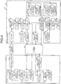
- FIG. 4 is a diagram illustrating an example functional configuration of a quantum communication system 100 according to the second arrangement.
- the quantum communication system 100 according to the second arrangement includes the transmitting device 10 and the receiver 20.
- the transmitting device 10 and the receiver 20 are connected with each other through the quantum channel 1.
- the transmitting device 10 and the receiver 20 are connected with each other through the classical channel 2.
- the transmitting device 10 includes the transmitter 11, the sifting processor 12, the generator 13, the retransmitter 14, and the privacy amplifier 15.
- the receiver 20 includes the receiver 21, the sifting processor 22, the determiner 23, a corrector 24, the retransmission controller 25, and the privacy amplifier 26.
- the second arrangement differs from the first arrangement in the operations of the corrector 24 and the retransmission controller 25, and thus, the description of the second arrangement will focus on the operations of the corrector 24 and the retransmission controller 25.
- the corrector 24 refers to the LDPC parameter 203 and the syndrome data 103 to correct errors in the sifted key data 202.
- the corrector 24 inputs the first corrected key data 204 and the retransmission control information 205 to the retransmission controller 25.
- the retransmission control information 205 includes reliability information in addition to the success/failure information and the error rate described above.
- the reliability information indicates reliability of the first corrected key data 204 or the second corrected key data 207.
- the reliability information is computed from the posterior value (log-likelihood ratio) described above.
- a greater absolute value of the posterior value means a higher probability that the data included in the sifted key data 202 is 0 or that the data is 1, thus indicating a higher reliability of the data.
- a threshold is set for the absolute value of the posterior value, and when the absolute value is below the threshold, the retransmission controller 25 determines that the data is not reliable. In other words, data, out of data included in each unsuccessfully error corrected block, determined to be unreliable will be the retransmission target data.
- the threshold of the posterior value will be considered.
- the posterior value is a log-likelihood ratio between the posterior probability that the data included in the sifted key data 202 is 1 and the posterior probability that the data included in the sifted key data 202 is 0.
- the retransmission controller 25 receives the first corrected key data 204 and the retransmission control information 205 from the corrector 24. When the retransmission request condition is satisfied, the retransmission controller 25 determines the address of data reliability of which is below the threshold in each unsuccessfully error corrected block to be the retransmission target address information, and transmits the retransmission request 206 including the retransmission target address information to the transmitting device 10 through the classical channel 2.
- the retransmitter 14 in the transmitting device 10 Upon reception of the retransmission request 206 from the retransmission controller 25 in the receiver 20, the retransmitter 14 in the transmitting device 10 acquires the data specified by the retransmission target address information included in the retransmission request 206 from the sifted key data 102 and transmits the data to the retransmission controller 25 as the retransmission key data 104.
- the retransmission controller 25 Upon reception of the retransmission key data 104 from the transmitting device 10 through the classical channel 2, the retransmission controller 25 inputs the retransmission key data 104 to the corrector 24.
- the corrector 24 Upon reception of the retransmission key data 104 from the retransmission controller 25, the corrector 24 replaces data, out of the data included in the first corrected key data 204, corresponding to the retransmission key data 104 with the retransmission key data 104, and generates replaced data. The corrector 24 then refers to the LDPC parameter 203 and the syndrome data 103 and performs error correction on the replaced data, thereby generating the second corrected key data 207 and the retransmission control information 205.
- the retransmission controller 25 Upon reception of the second corrected key data 207 and the retransmission control information 205 from the corrector 24, the retransmission controller 25 performs the retransmission control process again. The retransmission controller 25 repeats the retransmission control process until the retransmission request condition is no longer satisfied. When the retransmission request condition is not satisfied, the retransmission controller 25 inputs the first corrected key data 204 generated through a single error correction process, or the second corrected key data 207 generated through two or more error correction processes to the privacy amplifier 26. Differences between the first arrangement and the second arrangement have been described.
- FIG. 5 is a flowchart illustrating an example retransmission control process according to the second arrangement.
- the retransmission controller 25 refers to the retransmission control information 205 (success/failure information and reliability information) described above, and computes address information indicating the address of data included in each unsuccessfully error corrected block, the data reliability of which is below the threshold, as the retransmission target address (Step S21).
- the retransmission controller 25 determines whether the aforementioned retransmission request condition is satisfied (Step S22).
- Condition (1) is the same as the condition described in the first arrangement. That is, if there is an error correction block that has been unsuccessfully error corrected, the retransmission controller 25 requests retransmission.
- Condition (2) is basically the same as the condition described in the first arrangement.
- the retransmission controller 25 may request retransmission a plurality of times. In this regard, when the sum of data lengths of the retransmission key data 104 that has been retransmitted so far is smaller than the certain value T, the retransmission controller 25 requests retransmission.
- the retransmission request condition there are two possible combinations, a combination composed of Condition (1) and a combination composed of Conditions (1) and (2), in the same manner as in the first arrangement.
- the retransmission controller 25 determines whether all the error correction blocks that are the divided portions of the sifted key data 202 have been successfully error corrected (Step S23).
- the retransmission controller 25 inputs the first corrected key data 204 or the second corrected key data 207 to the privacy amplifier 26 (Step S24).
- the procedure is ended.
- the first corrected key data 204 or the second corrected key data 207 is not input to the privacy amplifier 26, and the sifted key data 102 is not input to the privacy amplifier 15.
- the procedure is ended.
- the retransmission controller 25 transmits the retransmission request 206 to the transmitting device 10 through the classical channel 2 (Step S25).
- the retransmission controller 25 receives the retransmission key data 104 from the transmitting device 10 through the classical channel 2 (Step S26).
- the corrector replaces data (data at the retransmission target address) included in the data of each unsuccessfully error corrected block of the first corrected key data 204 with the retransmission key data 104, and generates replaced data (Step S27).
- the corrector 24 then refers to the LDPC parameter 203 and the syndrome data 103 and performs error correction on the replaced data, thereby generating the second corrected key data 207 and the retransmission control information 205 (Step S28). The procedure returns to Step S21.
- the replaced data is generated at Step S27 by replacing data (data at the retransmission target address) included in the data of each unsuccessfully error corrected block of the second corrected key data 207 with the retransmission key data 104.
- the corrector 24 performs error correction on the sifted key data 202 (received key data) received from the transmitting device 10 through the quantum channel 1 and generates the first corrected key data 204.
- the retransmission controller 25 transmits the retransmission request 206 including the retransmission target address information (in the second arrangement, an address of unreliable data in each unsuccessfully error corrected block) to the transmitting device 10 through the classical channel 2 (control channel), and receives the retransmission key data 104 corresponding to the retransmission target address information from the transmitting device 10 through the classical channel 2.
- the corrector 24 replaces corrected key data at the retransmission target address with the retransmission key data 104 to generate replaced data, and further corrects the replaced data.
- the receiver 20 according to the second arrangement can prevent lowering of the generation rate of a cryptographic key if failures in error correction occur frequently.
- the receiver 20 according to the second arrangement can reduce the amount of data on which the eavesdropper may eavesdrop through the classical channel 2 compared to the first arrangement.
- FIG. 6 is a diagram illustrating an example hardware configuration of main units of the transmitting device 10 and the receiver 20 according to the first and the second arrangements.
- the transmitting device 10 and the receiver 20 according to the first and the second arrangements each include a control device 301, a main storage 302, a auxiliary storage 303, a display device 304, an input device 305, a quantum communication interface (IF) 306, and a classical communication IF 307.
- IF quantum communication interface
- the control device 301, the main storage 302, the auxiliary storage 303, the display device 304, the input device 305, the quantum communication IF 306, and the classical communication IF 307 are connected with each other through a bus 310.
- the control device 301 executes a computer program read from the auxiliary storage 303 onto the main storage 302.
- the main storage 302 may include, for example, a read only memory (ROM) and a random access memory (RAM).
- the auxiliary storage 303 may include, for example, a hard disk drive (HDD) and a memory card.
- the display device 304 displays, for example, states of the transmitting device 10 and the receiver 20.
- the input device 305 receives inputs from a user.
- the quantum communication IF 306 is an interface for connecting to the quantum channel 1.
- the classical communication IF 307 is an interface for connecting to the classical channel 2.
- the transmitting device 10 and the receiver 20 according to the first and the second arrangements can be implemented by any device such as a general-purpose computer including the hardware configuration illustrated in FIG. 6 .
- the computer program executed by the transmitting device 10 and the receiver 20 according to the first and the second arrangements above is recorded in a computer-readable recording medium such as a compact disc read only memory (CD-ROM), a memory card, a compact disc recordable (CD-R), and a digital versatile disc (DVD), as an installable or executable file, and provided as a computer program product.
- a computer-readable recording medium such as a compact disc read only memory (CD-ROM), a memory card, a compact disc recordable (CD-R), and a digital versatile disc (DVD), as an installable or executable file, and provided as a computer program product.
- the computer program executed by the transmitting device 10 and the receiver 20 according to the first and the second arrangements above may be stored in a computer connected to a network such as the Internet and provided by being downloaded through the network.
- the computer program executed by the transmitting device 10 and the receiver 20 according to the first and the second arrangements above may be provided through a network such as the Internet without being downloaded.
- the computer program executed by the transmitting device 10 and the receiver 20 according to the first and the second arrangements above may be embedded and provided in a ROM, for example.
- the computer program executed by the transmitting device 10 and the receiver 20 according to the first and the second arrangements above has a modular configuration including a function, out of the functions of the transmitting device 10 and the receiver 20 according to the first and the second arrangements, that can be implemented by the computer program.
- the function implemented by the computer program is implemented such that the control device 301 reads the computer program from a storage medium such as the auxiliary storage 303 and executes it, and the function is loaded on the main storage 302. In other words, the function implemented by the computer program is generated on the main storage 302.
- the IC is a processor that performs, for example, specialized processing.
- each processor may implement a single function, or may implement two or more functions.
- the transmitting device 10 and the receiver 20 according to the first and the second arrangements above may be operated in any way.
- the transmitting device 10 and the receiver 20 according to the first and the second arrangements above may be operated, for example, as devices that configure a cloud system on a network.
- the quantum communication device the quantum communication system, and the quantum communication method of at least one arrangement described above, it is possible to prevent lowering of the generation rate of a cryptographic key if failures in error correction occur frequently.
Landscapes
- Engineering & Computer Science (AREA)
- Physics & Mathematics (AREA)
- Electromagnetism (AREA)
- Computer Networks & Wireless Communication (AREA)
- Signal Processing (AREA)
- Theoretical Computer Science (AREA)
- Computer Security & Cryptography (AREA)
- Optics & Photonics (AREA)
- Detection And Prevention Of Errors In Transmission (AREA)
Abstract
Description
- The present disclosure relates to a quantum communication device, a quantum communication system, and a quantum communication method.
- Developments in the information communication technology made it possible to send and receive various types of data. Accordingly, ensuring privacy and security in transmitting information has become of greater importance. Quantum cryptography has been introduced in communication technology as an encryption scheme that is unbreakable even if computers have enough computing power, and many efforts have been made for its practical implementation. One of the efforts to practically implement the quantum cryptography in the communication technology is, for example, to study error correction technologies, and various types of error correction technologies have been developed. Among them, low-density parity-check (LDPC) codes have recently attracted attention as an error correction code that has an error correction capability very close to the theoretical maximum (the Shannon limit).
- In the conventional technologies, however, it is difficult to prevent lowering of the generation rate of a cryptographic key if error correction occurs frequently.
-
-
FIG. 1 is a diagram illustrating an example device configuration of a quantum communication system according to a first arrangement; -
FIG. 2 is a diagram illustrating an example functional configuration of the quantum communication system according to the first arrangement; -
FIG. 3 is a flowchart illustrating an example retransmission control process according to the first arrangement; -
FIG. 4 is a diagram illustrating an example functional configuration of a quantum communication system according to a second arrangement; -
FIG. 5 is a flowchart illustrating an example retransmission control process according to the second arrangement; and -
FIG. 6 is a diagram illustrating an example hardware configuration of main units of a transmitting device and a receiver according to the first and the second arrangements. - According to an arrangement, a quantum communication device includes a corrector and a retransmission controller. The corrector is configured to generate corrected key data by performing error correction on received key data received from a transmitting device through a quantum channel. The retransmission controller is configured to transmit a retransmission request including retransmission target address information to the transmitting device through a control channel when a retransmission request condition is satisfied, and receive retransmission key data corresponding to the retransmission target address information from the transmitting device through the control channel. After receiving the retransmission key data, the corrector replaces corrected key data corresponding to the retransmission target address information with the retransmission key data.
- The following describes arrangements of a quantum communication device, a quantum communication system, and a quantum communication method with reference to the accompanying drawings.
- Described first is a first arrangement.
-
FIG. 1 is a diagram illustrating an example device configuration of aquantum communication system 100 according to the first arrangement. Thequantum communication system 100 according to the first arrangement includes two quantum communication devices (a transmittingdevice 10 and a receiver 20). The transmittingdevice 10 sequentially transmits photons indicating quantum bits to thereceiver 20. For convenience of explanation, the device that transmits photons is referred to as the transmittingdevice 10 in the first arrangement, but the transmittingdevice 10 may include a function of receiving photons. In the same manner, thereceiver 20 may include a function of transmitting photons. - The transmitting
device 10 and thereceiver 20 transmit and receive encrypted data using quantum key data. The method of generating quantum key data will be described in detail below with reference toFIG. 2 . -
FIG. 2 is a diagram illustrating an example functional configuration of thequantum communication system 100 according to the first arrangement. Thequantum communication system 100 according to the first arrangement includes the transmittingdevice 10 and thereceiver 20. - The transmitting
device 10 and thereceiver 20 are connected with each other through a quantum channel 1. The quantum channel 1 is an optical fiber through which transmission photon data 101 indicating a quantum bit string is transmitted. The quantum channel 1 conveys single photons that are very weak light particles, thus susceptible to disturbance. - The transmitting
device 10 and thereceiver 20 are connected with each other through a classical channel 2. The classical channel 2 is a control channel through which control information for generating quantum key data 105 (208) is transmitted and received. As illustrated inFIG. 2 , for example, the control information includes anLDPC parameter 203,syndrome data 103, aretransmission request 206, andretransmission key data 104. The classical channel 2 may be a wired channel or a wireless channel, and may be implemented by both wired and wireless channels. - The
transmitting device 10 includes a transmitter 11, asifting processor 12, agenerator 13, a retransmitter 14, and aprivacy amplifier 15. - The
receiver 20 includes areceiver 21, a sifting processor 22, adeterminer 23, a first corrector 24-1, a second corrector 24-2, aretransmission controller 25, and a privacy amplifier 26. - The transmitter 11 transmits the transmission photon data 101 to the
receiver 21 through the quantum channel 1. The quantum bits configuring the transmission photon data 101 are each expressed by one of a plurality of bases using the quantum states of the photon. For the bases, properties of the photon such as its polarization or phase are used. - The
receiver 21 receives the transmission photon data 101 from the transmitter 11 through the quantum channel 1, thereby acquiring receivedphoton data 201. - The sifting processor 22 performs a sifting process in which the sifting processor 22 refers to the received
photon data 201 for each certain bit string in reference bases randomly selected from a plurality of bases and acquires sifted key data 202 (received key data). The sifting processor 22 inputs the siftedkey data 202 to thedeterminer 23 and to the first corrector 24-1. - Meanwhile, the
sifting processor 12 in the transmittingdevice 10 performs the sifting process on the transmission photon data 101 and acquires siftedkey data 102. Thesifting processor 12 inputs the siftedkey data 102 to thegenerator 13 and to theprivacy amplifier 15. When the retransmitter 14 receives aretransmission request 206 from thereceiver 20, thesifting processor 12 inputs data, out of the siftedkey data 102, specified by theretransmission request 206 to the retransmitter 14. - Upon reception of the sifted
key data 202 from the sifting processor 22, thedeterminer 23 in thereceiver 20 determines anLDPC parameter 203 for use in error correction on the siftedkey data 202. TheLDPC parameter 203 may be determined by any method. Thedeterminer 23 determines theLDPC parameter 203 by using, for example, an error rate of the previously received siftedkey data 202 computed in the previous error correction. Thedeterminer 23 transmits theLDPC parameter 203 to thegenerator 13 in the transmittingdevice 10 through the classical channel 2. - The
generator 13 in thetransmitting device 10 receives theLDPC parameter 203 from thedeterminer 23 in thereceiver 20 and receives the siftedkey data 102 from thesifting processor 12. Thegenerator 13 generatessyndrome data 103 from the siftedkey data 102 by using theLDPC parameter 203. Thegenerator 13 transmits thesyndrome data 103 to the first corrector 24-1 in thereceiver 20 through the classical channel 2. - The first corrector 24-1 in the
receiver 20 receives thesyndrome data 103 from thegenerator 13 in thetransmitting device 10, receives theLDPC parameter 203 from thedeterminer 23, and receives the siftedkey data 202 from the sifting processor 22. - The first corrector 24-1 divides the sifted
key data 202 into one or more error correction blocks and performs error correction on each error correction block. The first corrector 24-1 is implemented by, for example, an LDPC decoder. The first corrector 24-1 uses thesyndrome data 103 and theLDPC parameter 203 to perform error correction on the sifted key data 202 (one or more error correction blocks), thereby generating first correctedkey data 204 andretransmission control information 205. - The first corrected
key data 204 is binary data converted from a posterior value (analog value) of the siftedkey data 202. The posterior value is computed upon execution of error correction (LDPC decoding). The posterior value is a log-likelihood ratio between a posterior probability that the data included in the siftedkey data 202 is 1 and a posterior probability that the data included in the siftedkey data 202 is 0, as a result of LDPC decoding. When the posterior value is positive, the probability that the data is 1 is higher, whereas when the posteriori value is negative, the probability that the data is 0 is higher. When the posterior value is zero or greater, the first corrector 24-1 sets the data corresponding to the posterior value to be 1, and when the posterior value is smaller than zero, the first corrector 24-1 sets the data corresponding to the posterior value to be 0, and generates the first correctedkey data 204 from the siftedkey data 202. - The
retransmission control information 205 is information for use in retransmission control of theretransmission controller 25. Theretransmission control information 205 includes, for example, success/failure information and an error rate. - The success/failure information indicates success or failure in error correction for each error correction block. For example, the success/failure information indicates success when it is 1, and indicates failure when it is 0. The error rate indicates the error rate of the sifted
key data 202. The error rate of the siftedkey data 202 is computed by comparing the first correctedkey data 204 with the siftedkey data 202 when the error correction on the one or more error correction blocks is successfully performed. - The first corrector 24-1 inputs the first corrected
key data 204 and theretransmission control information 205 to theretransmission controller 25. - The
retransmission controller 25 receives the first correctedkey data 204 and theretransmission control information 205 from the first corrector 24-1. Theretransmission controller 25 refers to theretransmission control information 205 to determine whether a retransmission request condition is satisfied. Details of the retransmission request condition will be described later with reference toFIG. 3 . - When the retransmission request condition is not satisfied and when all the error correction blocks that are the divided portions of the sifted
key data 202 are successfully error corrected, theretransmission controller 25 inputs the first correctedkey data 204 to the privacy amplifier 26. - When the retransmission request condition is satisfied, the
retransmission controller 25 transmits theretransmission request 206 to the transmittingdevice 10 through the classical channel 2. - The
retransmission request 206 includes retransmission target address information. The retransmission target address information according to the first arrangement indicates the entire address of each unsuccessfully error corrected block. - Upon reception of the
retransmission request 206 from theretransmission controller 25 in thereceiver 20, the retransmitter 14 in the transmittingdevice 10 acquires data specified by the retransmission target address information included in theretransmission request 206 from the siftedkey data 102 and transmits the data to theretransmission controller 25 as retransmissionkey data 104. - Upon reception of the retransmission
key data 104 from the transmittingdevice 10 through the classical channel 2, theretransmission controller 25 inputs the retransmissionkey data 104 and the first correctedkey data 204 to the second corrector 24-2. - Upon reception of the retransmission
key data 104 and the first correctedkey data 204 from theretransmission controller 25, the second corrector 24-2 replaces data (error correction blocks in the first arrangement) corresponding to the retransmission target address information with the retransmissionkey data 104, thereby correcting the first correctedkey data 204. The second corrector 24-2 inputs second correctedkey data 207, which is generated by correcting the first correctedkey data 204, to the privacy amplifier 26. - Although
FIG. 2 illustrates the first corrector 24-1 and the second corrector 24-2 as units for performing error correction, the first corrector 24-1 and the second corrector 24-2 may be implemented by a single corrector. - Upon reception of the first corrected
key data 204 from theretransmission controller 25, the privacy amplifier 26 performs privacy amplification on the first correctedkey data 204 and generates quantumkey data 208. In the same manner, upon reception of the second correctedkey data 207 from the second corrector 24-2, the privacy amplifier 26 performs privacy amplification on the second correctedkey data 207 and generates the quantumkey data 208. - The privacy amplification is a process of amplifying privacy in generating the quantum
key data 208 by compressing the first correctedkey data 204 or the second correctedkey data 207. - Meanwhile, upon reception of the sifted
key data 102 from the siftingprocessor 12, theprivacy amplifier 15 in the transmittingdevice 10 performs privacy amplification on the siftedkey data 102 and generates quantumkey data 105 that is identical to the quantumkey data 208. -
FIG. 3 is a flowchart illustrating an example retransmission control process according to the first arrangement. First, theretransmission controller 25 determines whether the retransmission request condition is satisfied (Step S1). Details of the retransmission request condition will be described later. - If the retransmission request condition is not satisfied (No at Step S1), the
retransmission controller 25 determines whether all the error correction blocks that are the divided portions of the siftedkey data 202 have been successfully error corrected (Step S2). - If all the error correction blocks have been successfully error corrected (Yes at Step S2), the
retransmission controller 25 inputs the first correctedkey data 204 to the privacy amplifier 26 (Step S3). - If not all the error correction blocks have been successfully error corrected (No at Step S2), the procedure is ended. In this case, the first corrected
key data 204 is not input to the privacy amplifier 26, and the siftedkey data 102 is not input to theprivacy amplifier 15. In other words, when the error correction is unsuccessfully performed and the retransmission request condition is not satisfied, the procedure is ended. - If the retransmission request condition is satisfied (Yes at Step S1), the
retransmission controller 25 transmits theretransmission request 206 to the transmittingdevice 10 through the classical channel 2 (Step S4). Theretransmission controller 25 then receives the retransmissionkey data 104 from the transmittingdevice 10 through the classical channel 2 (Step S5). The second corrector 24-2 replaces data of unsuccessfully error corrected blocks included in the first correctedkey data 204 with the retransmissionkey data 104 to generate second corrected key data 207 (Step S6). The second corrector 24-2 inputs the second correctedkey data 207 to the privacy amplifier 26 (Step S7). - Described next are details of the retransmission request condition. The retransmission request condition includes, for example, Conditions (1) and (2) below.
- Condition (1): There is an error correction block that has been unsuccessfully error corrected.
- Condition (2): The sum of data lengths of the retransmission
key data 104 is smaller than a certain value. - Condition (1) is a retransmission request condition that can be used in, for example, automatic repeat request (ARQ) protocols. Using Condition (1) as the retransmission request condition can reduce the probability of failure in error correction, thereby preventing lowering of the key generation rate caused by the correction failure. In particular, this configuration has a significant improving effect in executing an error correction instruction compared to a case in which data is divided into a plurality of error correction blocks and, when not all of the error correction blocks are successfully error corrected, the entire first corrected
key data 204 is discarded. - Suppose that, for example, the first corrector 24-1 divides the sifted
key data 202 into ten error correction blocks upon execution of an error correction instruction and transmits the siftedkey data 202 to the privacy amplifier 26 only when all of the error correction blocks are successfully error corrected. In this case, when Condition (1) is not used in the retransmission control scheme, the entire data of the ten error corrected blocks is discarded upon failure in error correction on a single block. - Meanwhile, when Condition (1) is used in the retransmission control scheme, the second corrector 24-2 replaces data of unsuccessfully error corrected blocks included in the first corrected
key data 204 with the retransmissionkey data 104 and generates the second correctedkey data 207, and the second correctedkey data 207 is transmitted to the privacy amplifier 26. The retransmissionkey data 104 is transmitted through the classical channel 2, and thus the retransmissionkey data 104 is publicized in a common network. In this regard, the privacy amplifier 26 increases the compression rate in the privacy amplification in accordance with the data length of the retransmissionkey data 104, thereby ensuring privacy of the quantumkey data 208. - Condition (2) relates to the size of data publicly transmitted in the classical channel 2 in executing the error correction and to a compression rate in the privacy amplification. In the error correction according to the first arrangement, the
syndrome data 103 and the retransmissionkey data 104 are transmitted through the classical channel 2, and thus thesyndrome data 103 and the retransmissionkey data 104 are publicized. - The compression rate in the privacy amplification increases as the amount of data publicly transmitted is larger, and when the amount of data equates to a certain value T or greater, the compression rate will be zero or below zero. Let the data length of public data with which the compression rate in privacy amplification will be zero be L, and let the syndrome length in error correction be S, the certain value T is expressed as L - S. The data length L of the public data is determined in accordance with the error rate of the sifted
key data 202. - In the first arrangement, the data length of the retransmission
key data 104 is a sum of data lengths of all the data of the unsuccessfully error corrected blocks. When the sum is smaller than the certain value T, theretransmission controller 25 performs the retransmission process, whereas when the sum is the certain value T or greater, theretransmission controller 25 does not perform the retransmission process. - Adding Condition (2) to Condition (1) can prevent the
retransmission controller 25 from performing useless retransmission processes, thereby increasing the generation rate of the quantumkey data 208. - When, for example, most of the ten error correction blocks are incorrect and the retransmission process is performed, the data length L of the public data will be large. Thus, the compression rate in the privacy amplification will be zero or below zero, which will make the retransmission process useless, and thus, the
retransmission controller 25 does not perform the retransmission process. - Described next is the detail of the computation method of the certain value T. Lucamarini discloses the following Equation (1) as an equation for computing a compression rate r for use in privacy amplification.

- The first term on the right-hand side of Equation (1) indicates to which extent the eavesdropper eavesdrops on the transmission photon data 101 transmitted from the transmitter 11. When the first term on the right-hand side of Equation (1) is zero, it indicates that the eavesdropper eavesdrops on all the transmission photon data 101. When the first term on the right-hand side of Equation (1) is one, it indicates that the eavesdropper eavesdrops on no transmission photon data 101. The first term on the right-hand side of Equation (1) is computed based on, for example, an error rate of the sifted
key data 202, and is closer to zero as the error rate increases. - The term leakEC in Equation (1) accounts for the amount of data publicly transmitted through the classical channel 2 during error correction. As described above, in the first arrangement, the
syndrome data 103 and the retransmissionkey data 104 are publicly transmitted through the classical channel 2. The amount of leakEC increases as the sum of the data length of thesyndrome data 103 and the data length of the retransmissionkey data 104 increases, which results in a smaller compression rate r. - In Equation (1), Δ represents data indicating the finite length effect of the quantum
key data 208. An error rate Q of the siftedkey data 202 can be obtained by comparing the error correction blocks that are successfully error corrected with data corresponding to these error correction blocks in the siftedkey data 202. Once the error rate Q of the sifted key data is obtained, the value of leakEC and the data length L with which the compression rate r will be zero can be obtained from Equation (1) and the error rate Q. Thus, the certain value T can be obtained from L - S as described above. - The
retransmission controller 25 may use, for example, Condition (1) as the retransmission request condition. Theretransmission controller 25 may use, for example, both Conditions (1) and (2) as the retransmission request condition. - The error correction in the first arrangement is described as decoding of LDPC codes, for example, but the error correction is not limited to LDPC decoding. The error correction may be, for example, decoding of Bose-Chaudhuri-Hocquenghem (BCH) codes or decoding of Reed-Solomon (RS) codes.
- As described above, in the receiver 20 (quantum communication device) according to the first arrangement, the first corrector 24-1 performs error correction on the sifted key data 202 (received key data) received from the transmitting
device 10 through the quantum channel 1 and generates the first correctedkey data 204. When the retransmission request condition is satisfied, theretransmission controller 25 transmits theretransmission request 206 including the retransmission target address information (in the first arrangement, the entire address of each error correction block that has been unsuccessfully error corrected) to the transmittingdevice 10 through the classical channel 2 (control channel), and receives the retransmissionkey data 104 corresponding to the retransmission target address information from the transmittingdevice 10 through the classical channel 2. The second corrector 24-2 replaces corrected key data corresponding to the retransmission target address information with the retransmissionkey data 104, thereby correcting the first correctedkey data 204. - The first corrector 24-1 and the second corrector 24-2 may be implemented by a single corrector.
- The
receiver 20 according to the first arrangement can prevent lowering of the generation rate of a cryptographic key if failures in error correction occur frequently. - Described next is a second arrangement. In the description of the second arrangement, explanations similar to the first arrangement are omitted and differences from the first arrangement are described. In the first arrangement, the whole data of unsuccessfully error corrected blocks is retransmitted. In the second arrangement, however, the retransmission
key data 104 to be retransmitted does not include the whole data of the unsuccessfully error corrected blocks, but includes part of data included in the unsuccessfully error corrected blocks. This configuration can reduce the amount of data on which the eavesdropper may eavesdrop in the classical channel 2. -
FIG. 4 is a diagram illustrating an example functional configuration of aquantum communication system 100 according to the second arrangement. Thequantum communication system 100 according to the second arrangement includes the transmittingdevice 10 and thereceiver 20. The transmittingdevice 10 and thereceiver 20 are connected with each other through the quantum channel 1. The transmittingdevice 10 and thereceiver 20 are connected with each other through the classical channel 2. - The transmitting
device 10 includes the transmitter 11, the siftingprocessor 12, thegenerator 13, the retransmitter 14, and theprivacy amplifier 15. Thereceiver 20 includes thereceiver 21, the sifting processor 22, thedeterminer 23, acorrector 24, theretransmission controller 25, and the privacy amplifier 26. - The second arrangement differs from the first arrangement in the operations of the
corrector 24 and theretransmission controller 25, and thus, the description of the second arrangement will focus on the operations of thecorrector 24 and theretransmission controller 25. - The
corrector 24 refers to theLDPC parameter 203 and thesyndrome data 103 to correct errors in the siftedkey data 202. Thecorrector 24 inputs the first correctedkey data 204 and theretransmission control information 205 to theretransmission controller 25. - The
retransmission control information 205 according to the second arrangement includes reliability information in addition to the success/failure information and the error rate described above. The reliability information indicates reliability of the first correctedkey data 204 or the second correctedkey data 207. The reliability information is computed from the posterior value (log-likelihood ratio) described above. A greater absolute value of the posterior value means a higher probability that the data included in the siftedkey data 202 is 0 or that the data is 1, thus indicating a higher reliability of the data. In this regard, a threshold is set for the absolute value of the posterior value, and when the absolute value is below the threshold, theretransmission controller 25 determines that the data is not reliable. In other words, data, out of data included in each unsuccessfully error corrected block, determined to be unreliable will be the retransmission target data. - In this paragraph, the threshold of the posterior value will be considered. The posterior value is a log-likelihood ratio between the posterior probability that the data included in the sifted
key data 202 is 1 and the posterior probability that the data included in the siftedkey data 202 is 0. Suppose that, for example, the higher one of the posterior probabilities is 90% or greater and the lower one is 10% or smaller, and that the data is reliable, the threshold for the absolute value of the posterior value is 2.197 (≈ log(0.9/0.1) = |log(0.1/0.9)|). Accordingly, when the absolute value of the posterior value is 2.197 or greater, theretransmission controller 25 determines that the data corresponding to the posterior value is reliable. When the absolute value of the posterior value is smaller than 2.197, theretransmission controller 25 determines that the data corresponding to the posterior value is not reliable. - The
retransmission controller 25 receives the first correctedkey data 204 and theretransmission control information 205 from thecorrector 24. When the retransmission request condition is satisfied, theretransmission controller 25 determines the address of data reliability of which is below the threshold in each unsuccessfully error corrected block to be the retransmission target address information, and transmits theretransmission request 206 including the retransmission target address information to the transmittingdevice 10 through the classical channel 2. - Upon reception of the
retransmission request 206 from theretransmission controller 25 in thereceiver 20, the retransmitter 14 in the transmittingdevice 10 acquires the data specified by the retransmission target address information included in theretransmission request 206 from the siftedkey data 102 and transmits the data to theretransmission controller 25 as the retransmissionkey data 104. - Upon reception of the retransmission
key data 104 from the transmittingdevice 10 through the classical channel 2, theretransmission controller 25 inputs the retransmissionkey data 104 to thecorrector 24. - Upon reception of the retransmission
key data 104 from theretransmission controller 25, thecorrector 24 replaces data, out of the data included in the first correctedkey data 204, corresponding to the retransmissionkey data 104 with the retransmissionkey data 104, and generates replaced data. Thecorrector 24 then refers to theLDPC parameter 203 and thesyndrome data 103 and performs error correction on the replaced data, thereby generating the second correctedkey data 207 and theretransmission control information 205. - Upon reception of the second corrected
key data 207 and theretransmission control information 205 from thecorrector 24, theretransmission controller 25 performs the retransmission control process again. Theretransmission controller 25 repeats the retransmission control process until the retransmission request condition is no longer satisfied. When the retransmission request condition is not satisfied, theretransmission controller 25 inputs the first correctedkey data 204 generated through a single error correction process, or the second correctedkey data 207 generated through two or more error correction processes to the privacy amplifier 26. Differences between the first arrangement and the second arrangement have been described. -
FIG. 5 is a flowchart illustrating an example retransmission control process according to the second arrangement. First, theretransmission controller 25 refers to the retransmission control information 205 (success/failure information and reliability information) described above, and computes address information indicating the address of data included in each unsuccessfully error corrected block, the data reliability of which is below the threshold, as the retransmission target address (Step S21). - The
retransmission controller 25 then determines whether the aforementioned retransmission request condition is satisfied (Step S22). Condition (1) is the same as the condition described in the first arrangement. That is, if there is an error correction block that has been unsuccessfully error corrected, theretransmission controller 25 requests retransmission. Condition (2) is basically the same as the condition described in the first arrangement. In the second arrangement, theretransmission controller 25 may request retransmission a plurality of times. In this regard, when the sum of data lengths of the retransmissionkey data 104 that has been retransmitted so far is smaller than the certain value T, theretransmission controller 25 requests retransmission. With regard to the retransmission request condition, there are two possible combinations, a combination composed of Condition (1) and a combination composed of Conditions (1) and (2), in the same manner as in the first arrangement. - If the retransmission request condition is not satisfied (No at Step S22), the
retransmission controller 25 determines whether all the error correction blocks that are the divided portions of the siftedkey data 202 have been successfully error corrected (Step S23). - If all the error correction blocks have been successfully error corrected (Yes at Step S23), the
retransmission controller 25 inputs the first correctedkey data 204 or the second correctedkey data 207 to the privacy amplifier 26 (Step S24). - If not all the error correction blocks are successfully error corrected (No at Step S23), the procedure is ended. In this case, the first corrected
key data 204 or the second correctedkey data 207 is not input to the privacy amplifier 26, and the siftedkey data 102 is not input to theprivacy amplifier 15. In other words, if the error correction is unsuccessfully performed and the retransmission request condition is not satisfied, the procedure is ended. - If the retransmission request condition is satisfied (Yes at Step S22), the
retransmission controller 25 transmits theretransmission request 206 to the transmittingdevice 10 through the classical channel 2 (Step S25). Theretransmission controller 25 then receives the retransmissionkey data 104 from the transmittingdevice 10 through the classical channel 2 (Step S26). Subsequently, the corrector replaces data (data at the retransmission target address) included in the data of each unsuccessfully error corrected block of the first correctedkey data 204 with the retransmissionkey data 104, and generates replaced data (Step S27). Thecorrector 24 then refers to theLDPC parameter 203 and thesyndrome data 103 and performs error correction on the replaced data, thereby generating the second correctedkey data 207 and the retransmission control information 205 (Step S28). The procedure returns to Step S21. - From the second round of the procedure, the replaced data is generated at Step S27 by replacing data (data at the retransmission target address) included in the data of each unsuccessfully error corrected block of the second corrected
key data 207 with the retransmissionkey data 104. - As described above, in the receiver 20 (quantum communication device) according to the second arrangement, the
corrector 24 performs error correction on the sifted key data 202 (received key data) received from the transmittingdevice 10 through the quantum channel 1 and generates the first correctedkey data 204. When the retransmission request condition is satisfied, theretransmission controller 25 transmits theretransmission request 206 including the retransmission target address information (in the second arrangement, an address of unreliable data in each unsuccessfully error corrected block) to the transmittingdevice 10 through the classical channel 2 (control channel), and receives the retransmissionkey data 104 corresponding to the retransmission target address information from the transmittingdevice 10 through the classical channel 2. Thecorrector 24 replaces corrected key data at the retransmission target address with the retransmissionkey data 104 to generate replaced data, and further corrects the replaced data. - The
receiver 20 according to the second arrangement can prevent lowering of the generation rate of a cryptographic key if failures in error correction occur frequently. Thereceiver 20 according to the second arrangement can reduce the amount of data on which the eavesdropper may eavesdrop through the classical channel 2 compared to the first arrangement. - Lastly, an example hardware configuration of the transmitting
device 10 and thereceiver 20 according to the first and the second arrangements will be described. -
FIG. 6 is a diagram illustrating an example hardware configuration of main units of the transmittingdevice 10 and thereceiver 20 according to the first and the second arrangements. The transmittingdevice 10 and thereceiver 20 according to the first and the second arrangements each include acontrol device 301, amain storage 302, aauxiliary storage 303, adisplay device 304, aninput device 305, a quantum communication interface (IF) 306, and a classical communication IF 307. - The
control device 301, themain storage 302, theauxiliary storage 303, thedisplay device 304, theinput device 305, the quantum communication IF 306, and the classical communication IF 307 are connected with each other through abus 310. - The
control device 301 executes a computer program read from theauxiliary storage 303 onto themain storage 302. Themain storage 302 may include, for example, a read only memory (ROM) and a random access memory (RAM). Theauxiliary storage 303 may include, for example, a hard disk drive (HDD) and a memory card. - The
display device 304 displays, for example, states of the transmittingdevice 10 and thereceiver 20. Theinput device 305 receives inputs from a user. - The quantum communication IF 306 is an interface for connecting to the quantum channel 1. The classical communication IF 307 is an interface for connecting to the classical channel 2.
- The transmitting
device 10 and thereceiver 20 according to the first and the second arrangements can be implemented by any device such as a general-purpose computer including the hardware configuration illustrated inFIG. 6 . - The computer program executed by the transmitting
device 10 and thereceiver 20 according to the first and the second arrangements above is recorded in a computer-readable recording medium such as a compact disc read only memory (CD-ROM), a memory card, a compact disc recordable (CD-R), and a digital versatile disc (DVD), as an installable or executable file, and provided as a computer program product. - The computer program executed by the transmitting
device 10 and thereceiver 20 according to the first and the second arrangements above may be stored in a computer connected to a network such as the Internet and provided by being downloaded through the network. - Furthermore, the computer program executed by the transmitting
device 10 and thereceiver 20 according to the first and the second arrangements above may be provided through a network such as the Internet without being downloaded. - The computer program executed by the transmitting
device 10 and thereceiver 20 according to the first and the second arrangements above may be embedded and provided in a ROM, for example. - The computer program executed by the transmitting
device 10 and thereceiver 20 according to the first and the second arrangements above has a modular configuration including a function, out of the functions of the transmittingdevice 10 and thereceiver 20 according to the first and the second arrangements, that can be implemented by the computer program. - The function implemented by the computer program is implemented such that the
control device 301 reads the computer program from a storage medium such as theauxiliary storage 303 and executes it, and the function is loaded on themain storage 302. In other words, the function implemented by the computer program is generated on themain storage 302. - Some or all of the functions of the transmitting
device 10 and thereceiver 20 according to the first and the second arrangements above may be implemented by hardware such as an integrated circuit (IC). The IC is a processor that performs, for example, specialized processing. - When the functions are implemented by a plurality of processors, each processor may implement a single function, or may implement two or more functions.
- The transmitting
device 10 and thereceiver 20 according to the first and the second arrangements above may be operated in any way. The transmittingdevice 10 and thereceiver 20 according to the first and the second arrangements above may be operated, for example, as devices that configure a cloud system on a network. - According to the quantum communication device, the quantum communication system, and the quantum communication method of at least one arrangement described above, it is possible to prevent lowering of the generation rate of a cryptographic key if failures in error correction occur frequently.
- While certain arrangements have been described, these arrangements have been presented by way of example only, and are not intended to limit the scope of the claims. Indeed, the novel devices described herein may be embodied in a variety of other forms; furthermore various omissions, substitutions and changes in the form of the devices described herein may be made.
- Example 1. A quantum communication device includes a corrector and a retransmission controller. The corrector is configured to generate corrected key data by performing error correction on received key data received from a transmitting device through a quantum channel. The retransmission controller is configured to transmit a retransmission request including retransmission target address information to the transmitting device through a control channel when a retransmission request condition is satisfied, and receive retransmission key data corresponding to the retransmission target address information from the transmitting device through the control channel. After receiving the retransmission key data, the corrector replaces corrected key data corresponding to the retransmission target address information with the retransmission key data.
- Example 2. In the quantum communication device according to Example 1, the corrector divides the received key data into a plurality of error correction blocks and performs error correction on each error correction block.
- Example 3. In the quantum communication device according to Example 2, the retransmission target address information indicates an entire address of an error correction block that has been unsuccessfully error corrected.
- Example 4. In the quantum communication device according to Example 2, the corrector is a low-density parity-check decoder configured to output information indicating success or failure in error correction on each error correction block, corrected key data of each error correction block, and reliability of data included in the corrected key data. The retransmission target address information indicates an address of data reliability of which is below a threshold, the data being included in an error correction block that has been unsuccessfully error corrected. After receiving the retransmission key data, the corrector replaces corrected key data corresponding to the retransmission target address information with the retransmission key data to generate replaced data, and performs error correction on the replaced data.
- Example 5. In the quantum communication device according to Example 4, the reliability is an absolute value of a log-likelihood ratio between a posterior probability that data included in the received key data is 1 and a posterior probability that data included in the received key data is 0.
- Example 6. In the quantum communication device according to Example 2, the retransmission request condition is that there is an error correction block that has been unsuccessfully error corrected.
- Example 7. In the quantum communication device according to any one of Examples 1 to 6, the retransmission request condition is that a sum of data lengths of the retransmission key data is smaller than a certain value.
- Example 8. In the quantum communication device according to Example 7, the certain value is a difference between a data length of public data, the data length with which a compression rate in privacy amplification performed after the error correction is zero, and a data length of syndrome data transmitted in the error correction.
- Example 9. A quantum communication system includes a transmitting device; and a receiver connected with the transmitting device through a quantum channel. The receiver includes a corrector and a retransmission controller. The corrector is configured to generate corrected key data by performing error correction on received key data received from the transmitting device through the quantum channel. The retransmission controller is configured to transmit a retransmission request including retransmission target address information to the transmitting device through a control channel when a retransmission request condition is satisfied, and receive retransmission key data corresponding to the retransmission target address information from the transmitting device through the control channel. After receiving the retransmission key data, the corrector replaces corrected key data corresponding to the retransmission target address information with the retransmission key data.
- Example 10. A quantum communication method includes: generating corrected key data by performing error correction on received key data received from a transmitting device through a quantum channel; transmitting a retransmission request including retransmission target address information to the transmitting device through a control channel when a retransmission request condition is satisfied, and receiving retransmission key data corresponding to the retransmission target address information from the transmitting device through the control channel; and replacing corrected key data corresponding to the retransmission target address information with the retransmission key data.
Claims (10)
- A quantum communication device (20) comprising:a corrector (24; 24-1) configured to generate corrected key data by performing error correction on received key data received from a transmitting device through a quantum channel; anda retransmission controller (25) configured totransmit a retransmission request including retransmission target address information to the transmitting device through a control channel when a retransmission request condition is satisfied, andreceive retransmission key data corresponding to the retransmission target address information from the transmitting device through the control channel, whereinafter receiving the retransmission key data, the corrector (24; 24-2) replaces corrected key data corresponding to the retransmission target address information with the retransmission key data.
- The quantum communication device (20) according to claim 1, wherein the corrector (24; 24-1) divides the received key data into a plurality of error correction blocks and performs error correction on each error correction block.
- The quantum communication device (20) according to claim 2, wherein the retransmission target address information indicates an entire address of an error correction block that has been unsuccessfully error corrected.
- The quantum communication device (20) according to claim 2, wherein
the corrector (24) is a low-density parity-check decoder configured to output information indicating success or failure in error correction on each error correction block, corrected key data of each error correction block, and reliability of data included in the corrected key data,
the retransmission target address information indicates an address of data reliability of which is below a threshold, the data being included in an error correction block that has been unsuccessfully error corrected, and
after receiving the retransmission key data, the corrector (24) replaces corrected key data corresponding to the retransmission target address information with the retransmission key data to generate replaced data, and performs error correction on the replaced data. - The quantum communication device (20) according to claim 4, wherein the reliability is an absolute value of a log-likelihood ratio between a posterior probability that data included in the received key data is 1 and a posterior probability that data included in the received key data is 0.
- The quantum communication device (20) according to claim 2, wherein the retransmission request condition is that there is an error correction block that has been unsuccessfully error corrected.
- The quantum communication device (20) according to any one of claims 1 to 6, wherein the retransmission request condition is that a sum of data lengths of the retransmission key data is smaller than a certain value.
- The quantum communication device (20) according to claim 7, wherein the certain value is a difference between a data length of public data, the data length with which a compression rate in privacy amplification performed after the error correction is zero, and a data length of syndrome data transmitted in the error correction.
- A quantum communication system (100) comprising:a transmitting device (10); anda receiving device (20) connected with the transmitting device (10) through a quantum channel (1), whereinthe receiving device (20) includesa corrector (24; 24-1) configured to generate corrected key data by performing error correction on received key data received from the transmitting device through the quantum channel; anda retransmission controller (25) configured totransmit a retransmission request including retransmission target address information to the transmitting device through a control channel when a retransmission request condition is satisfied, andreceive retransmission key data corresponding to the retransmission target address information from the transmitting device through the control channel, andafter receiving the retransmission key data, the corrector (24; 24-2) replaces corrected key data corresponding to the retransmission target address information with the retransmission key data.
- A quantum communication method comprising:generating corrected key data by performing error correction on received key data received from a transmitting device through a quantum channel;transmitting a retransmission request including retransmission target address information to the transmitting device through a control channel when a retransmission request condition is satisfied (S1, S4), and receiving retransmission key data corresponding to the retransmission target address information from the transmitting device through the control channel (S5); andreplacing corrected key data corresponding to the retransmission target address information with the retransmission key data (S7).
Applications Claiming Priority (1)
| Application Number | Priority Date | Filing Date | Title |
|---|---|---|---|
| JP2017116219 | 2017-06-13 |
Publications (2)
| Publication Number | Publication Date |
|---|---|
| EP3416332A1 true EP3416332A1 (en) | 2018-12-19 |
| EP3416332B1 EP3416332B1 (en) | 2020-04-08 |
Family
ID=61157076
Family Applications (1)
| Application Number | Title | Priority Date | Filing Date |
|---|---|---|---|
| EP18154870.2A Active EP3416332B1 (en) | 2017-06-13 | 2018-02-02 | Quantum communication device, quantum communication system and quantum communication method |
Country Status (3)
| Country | Link |
|---|---|
| US (1) | US20180359086A1 (en) |
| EP (1) | EP3416332B1 (en) |
| JP (1) | JP2019004467A (en) |
Cited By (1)
| Publication number | Priority date | Publication date | Assignee | Title |
|---|---|---|---|---|
| US12445275B2 (en) | 2020-08-24 | 2025-10-14 | Lg Electronics Inc. | Method and device for estimating quantum bit error rate on basis of maximum bit group and two-dimensional parity |
Families Citing this family (3)
| Publication number | Priority date | Publication date | Assignee | Title |
|---|---|---|---|---|
| US20210042650A1 (en) | 2019-08-06 | 2021-02-11 | Microsoft Technology Licensing, Llc | Pipelined hardware decoder for quantum computing devices |
| CN114745074B (en) * | 2022-03-08 | 2023-09-26 | 青岛理工大学 | Topological SEMION error correction method for quantum communication in noisy environment |
| JP2025524875A (en) * | 2022-07-21 | 2025-08-01 | キューシムプラス カンパニー リミテッド | Method and system for error correction in quantum cryptography communications |
Citations (2)
| Publication number | Priority date | Publication date | Assignee | Title |
|---|---|---|---|---|
| US20070071245A1 (en) * | 2005-09-28 | 2007-03-29 | Nortel Networks Limited | Methods and systems for communicating over a quantum channel |
| JP2011166292A (en) * | 2010-02-05 | 2011-08-25 | Nec Corp | Signal processing system, quantum encryption system, signal processing method and quantum encryption method |
-
2018
- 2018-02-02 EP EP18154870.2A patent/EP3416332B1/en active Active
- 2018-02-16 US US15/932,199 patent/US20180359086A1/en not_active Abandoned
- 2018-06-13 JP JP2018113176A patent/JP2019004467A/en active Pending
Patent Citations (2)
| Publication number | Priority date | Publication date | Assignee | Title |
|---|---|---|---|---|
| US20070071245A1 (en) * | 2005-09-28 | 2007-03-29 | Nortel Networks Limited | Methods and systems for communicating over a quantum channel |
| JP2011166292A (en) * | 2010-02-05 | 2011-08-25 | Nec Corp | Signal processing system, quantum encryption system, signal processing method and quantum encryption method |
Non-Patent Citations (2)
| Title |
|---|
| ANASTASE NAKASSIS , JOSHUA BIENFANG, CARL WILLIAMS: "Expeditious Reconciliation for Practical Quantum Key Distribution", SPIE, PO BOX 10 BELLINGHAM WA 98227-0010 USA, 24 August 2004 (2004-08-24), XP040185453 * |
| SUNGSIK YOON ET AL: "Efficient information reconciliation with turbo codes over the quantum channel", 2013 INTERNATIONAL CONFERENCE ON ICT CONVERGENCE (ICTC), IEEE, 14 October 2013 (2013-10-14), pages 1091 - 1092, XP032527254, DOI: 10.1109/ICTC.2013.6675563 * |
Cited By (1)
| Publication number | Priority date | Publication date | Assignee | Title |
|---|---|---|---|---|
| US12445275B2 (en) | 2020-08-24 | 2025-10-14 | Lg Electronics Inc. | Method and device for estimating quantum bit error rate on basis of maximum bit group and two-dimensional parity |
Also Published As
| Publication number | Publication date |
|---|---|
| JP2019004467A (en) | 2019-01-10 |
| US20180359086A1 (en) | 2018-12-13 |
| EP3416332B1 (en) | 2020-04-08 |
Similar Documents
| Publication | Publication Date | Title |
|---|---|---|
| US10680651B2 (en) | Signature-enabled polar encoder and decoder | |
| US7461323B2 (en) | Quantum key delivery method and communication device | |
| EP2348640B1 (en) | Systematic encoding of chain reaction codes | |
| US10454625B2 (en) | System and method for employing outer codes with non-equal length codeblocks field | |
| US20170104590A1 (en) | Method and Apparatus for Error Correcting Code Based Public Key Encryption Schemes | |
| JP4554523B2 (en) | Quantum key distribution method and communication apparatus | |
| US9467284B2 (en) | Transmitter, receiver, quantum key distribution (QKD) system and quantum key distribution method | |
| EP3416332B1 (en) | Quantum communication device, quantum communication system and quantum communication method | |
| US8850298B2 (en) | Combined Koetter-Vardy and Chase decoding of cyclic codes | |
| US9742438B2 (en) | Method and apparatus for cipher detection | |
| US20190052403A1 (en) | Forward error correction with contrast coding | |
| US9397793B2 (en) | Method for securely transmitting packets for wireless telecommunications system | |
| JP2018157411A (en) | Information processing device | |
| US20170019211A1 (en) | Method and device for decoding low density parity check code for forward error correction in wireless communication system | |
| JPWO2003007543A1 (en) | Shared data refining apparatus and shared data refining method | |
| US10447300B2 (en) | Decoding device, decoding method, and signal transmission system | |
| US20150263766A1 (en) | Method and apparatus for controlling interleaving depth | |
| Hashemi et al. | A modified McEliece public-Key cryptosystem based on irregular codes of QC-LDPC and QC-MDPC | |
| JP4231926B2 (en) | Quantum key distribution method and communication apparatus | |
| RU2611235C1 (en) | Method for and detection and correction of erased potions of received digital information | |
| JP2017143343A (en) | Data processing apparatus, communication system, and data processing method | |
| JP2012039450A (en) | Decoder and decoding method | |
| WO2015068765A1 (en) | Decoding device |
Legal Events
| Date | Code | Title | Description |
|---|---|---|---|
| PUAI | Public reference made under article 153(3) epc to a published international application that has entered the european phase |
Free format text: ORIGINAL CODE: 0009012 |
|
| STAA | Information on the status of an ep patent application or granted ep patent |
Free format text: STATUS: REQUEST FOR EXAMINATION WAS MADE |
|
| 17P | Request for examination filed |
Effective date: 20180202 |
|
| AK | Designated contracting states |
Kind code of ref document: A1 Designated state(s): AL AT BE BG CH CY CZ DE DK EE ES FI FR GB GR HR HU IE IS IT LI LT LU LV MC MK MT NL NO PL PT RO RS SE SI SK SM TR |
|
| AX | Request for extension of the european patent |
Extension state: BA ME |
|
| GRAP | Despatch of communication of intention to grant a patent |
Free format text: ORIGINAL CODE: EPIDOSNIGR1 |
|
| STAA | Information on the status of an ep patent application or granted ep patent |
Free format text: STATUS: GRANT OF PATENT IS INTENDED |
|
| INTG | Intention to grant announced |
Effective date: 20191112 |
|
| GRAS | Grant fee paid |
Free format text: ORIGINAL CODE: EPIDOSNIGR3 |
|
| GRAA | (expected) grant |
Free format text: ORIGINAL CODE: 0009210 |
|
| STAA | Information on the status of an ep patent application or granted ep patent |
Free format text: STATUS: THE PATENT HAS BEEN GRANTED |
|
| AK | Designated contracting states |
Kind code of ref document: B1 Designated state(s): AL AT BE BG CH CY CZ DE DK EE ES FI FR GB GR HR HU IE IS IT LI LT LU LV MC MK MT NL NO PL PT RO RS SE SI SK SM TR |
|
| REG | Reference to a national code |
Ref country code: AT Ref legal event code: REF Ref document number: 1255819 Country of ref document: AT Kind code of ref document: T Effective date: 20200415 Ref country code: CH Ref legal event code: EP |
|
| REG | Reference to a national code |
Ref country code: DE Ref legal event code: R096 Ref document number: 602018003476 Country of ref document: DE |
|
| REG | Reference to a national code |
Ref country code: IE Ref legal event code: FG4D |
|
| REG | Reference to a national code |
Ref country code: NL Ref legal event code: MP Effective date: 20200408 |
|
| REG | Reference to a national code |
Ref country code: LT Ref legal event code: MG4D |
|
| PG25 | Lapsed in a contracting state [announced via postgrant information from national office to epo] |
Ref country code: PT Free format text: LAPSE BECAUSE OF FAILURE TO SUBMIT A TRANSLATION OF THE DESCRIPTION OR TO PAY THE FEE WITHIN THE PRESCRIBED TIME-LIMIT Effective date: 20200817 Ref country code: IS Free format text: LAPSE BECAUSE OF FAILURE TO SUBMIT A TRANSLATION OF THE DESCRIPTION OR TO PAY THE FEE WITHIN THE PRESCRIBED TIME-LIMIT Effective date: 20200808 Ref country code: SE Free format text: LAPSE BECAUSE OF FAILURE TO SUBMIT A TRANSLATION OF THE DESCRIPTION OR TO PAY THE FEE WITHIN THE PRESCRIBED TIME-LIMIT Effective date: 20200408 Ref country code: NL Free format text: LAPSE BECAUSE OF FAILURE TO SUBMIT A TRANSLATION OF THE DESCRIPTION OR TO PAY THE FEE WITHIN THE PRESCRIBED TIME-LIMIT Effective date: 20200408 Ref country code: FI Free format text: LAPSE BECAUSE OF FAILURE TO SUBMIT A TRANSLATION OF THE DESCRIPTION OR TO PAY THE FEE WITHIN THE PRESCRIBED TIME-LIMIT Effective date: 20200408 Ref country code: LT Free format text: LAPSE BECAUSE OF FAILURE TO SUBMIT A TRANSLATION OF THE DESCRIPTION OR TO PAY THE FEE WITHIN THE PRESCRIBED TIME-LIMIT Effective date: 20200408 Ref country code: NO Free format text: LAPSE BECAUSE OF FAILURE TO SUBMIT A TRANSLATION OF THE DESCRIPTION OR TO PAY THE FEE WITHIN THE PRESCRIBED TIME-LIMIT Effective date: 20200708 Ref country code: GR Free format text: LAPSE BECAUSE OF FAILURE TO SUBMIT A TRANSLATION OF THE DESCRIPTION OR TO PAY THE FEE WITHIN THE PRESCRIBED TIME-LIMIT Effective date: 20200709 |
|
| REG | Reference to a national code |
Ref country code: AT Ref legal event code: MK05 Ref document number: 1255819 Country of ref document: AT Kind code of ref document: T Effective date: 20200408 |
|
| PG25 | Lapsed in a contracting state [announced via postgrant information from national office to epo] |
Ref country code: HR Free format text: LAPSE BECAUSE OF FAILURE TO SUBMIT A TRANSLATION OF THE DESCRIPTION OR TO PAY THE FEE WITHIN THE PRESCRIBED TIME-LIMIT Effective date: 20200408 Ref country code: LV Free format text: LAPSE BECAUSE OF FAILURE TO SUBMIT A TRANSLATION OF THE DESCRIPTION OR TO PAY THE FEE WITHIN THE PRESCRIBED TIME-LIMIT Effective date: 20200408 Ref country code: RS Free format text: LAPSE BECAUSE OF FAILURE TO SUBMIT A TRANSLATION OF THE DESCRIPTION OR TO PAY THE FEE WITHIN THE PRESCRIBED TIME-LIMIT Effective date: 20200408 Ref country code: BG Free format text: LAPSE BECAUSE OF FAILURE TO SUBMIT A TRANSLATION OF THE DESCRIPTION OR TO PAY THE FEE WITHIN THE PRESCRIBED TIME-LIMIT Effective date: 20200708 |
|
| PG25 | Lapsed in a contracting state [announced via postgrant information from national office to epo] |
Ref country code: AL Free format text: LAPSE BECAUSE OF FAILURE TO SUBMIT A TRANSLATION OF THE DESCRIPTION OR TO PAY THE FEE WITHIN THE PRESCRIBED TIME-LIMIT Effective date: 20200408 |
|
| REG | Reference to a national code |
Ref country code: DE Ref legal event code: R097 Ref document number: 602018003476 Country of ref document: DE |
|
| PG25 | Lapsed in a contracting state [announced via postgrant information from national office to epo] |
Ref country code: EE Free format text: LAPSE BECAUSE OF FAILURE TO SUBMIT A TRANSLATION OF THE DESCRIPTION OR TO PAY THE FEE WITHIN THE PRESCRIBED TIME-LIMIT Effective date: 20200408 Ref country code: RO Free format text: LAPSE BECAUSE OF FAILURE TO SUBMIT A TRANSLATION OF THE DESCRIPTION OR TO PAY THE FEE WITHIN THE PRESCRIBED TIME-LIMIT Effective date: 20200408 Ref country code: IT Free format text: LAPSE BECAUSE OF FAILURE TO SUBMIT A TRANSLATION OF THE DESCRIPTION OR TO PAY THE FEE WITHIN THE PRESCRIBED TIME-LIMIT Effective date: 20200408 Ref country code: CZ Free format text: LAPSE BECAUSE OF FAILURE TO SUBMIT A TRANSLATION OF THE DESCRIPTION OR TO PAY THE FEE WITHIN THE PRESCRIBED TIME-LIMIT Effective date: 20200408 Ref country code: AT Free format text: LAPSE BECAUSE OF FAILURE TO SUBMIT A TRANSLATION OF THE DESCRIPTION OR TO PAY THE FEE WITHIN THE PRESCRIBED TIME-LIMIT Effective date: 20200408 Ref country code: DK Free format text: LAPSE BECAUSE OF FAILURE TO SUBMIT A TRANSLATION OF THE DESCRIPTION OR TO PAY THE FEE WITHIN THE PRESCRIBED TIME-LIMIT Effective date: 20200408 Ref country code: SM Free format text: LAPSE BECAUSE OF FAILURE TO SUBMIT A TRANSLATION OF THE DESCRIPTION OR TO PAY THE FEE WITHIN THE PRESCRIBED TIME-LIMIT Effective date: 20200408 Ref country code: ES Free format text: LAPSE BECAUSE OF FAILURE TO SUBMIT A TRANSLATION OF THE DESCRIPTION OR TO PAY THE FEE WITHIN THE PRESCRIBED TIME-LIMIT Effective date: 20200408 |
|
| PLBE | No opposition filed within time limit |
Free format text: ORIGINAL CODE: 0009261 |
|
| STAA | Information on the status of an ep patent application or granted ep patent |
Free format text: STATUS: NO OPPOSITION FILED WITHIN TIME LIMIT |
|
| PG25 | Lapsed in a contracting state [announced via postgrant information from national office to epo] |
Ref country code: SK Free format text: LAPSE BECAUSE OF FAILURE TO SUBMIT A TRANSLATION OF THE DESCRIPTION OR TO PAY THE FEE WITHIN THE PRESCRIBED TIME-LIMIT Effective date: 20200408 Ref country code: PL Free format text: LAPSE BECAUSE OF FAILURE TO SUBMIT A TRANSLATION OF THE DESCRIPTION OR TO PAY THE FEE WITHIN THE PRESCRIBED TIME-LIMIT Effective date: 20200408 |
|
| 26N | No opposition filed |
Effective date: 20210112 |
|
| PG25 | Lapsed in a contracting state [announced via postgrant information from national office to epo] |
Ref country code: SI Free format text: LAPSE BECAUSE OF FAILURE TO SUBMIT A TRANSLATION OF THE DESCRIPTION OR TO PAY THE FEE WITHIN THE PRESCRIBED TIME-LIMIT Effective date: 20200408 |
|
| PG25 | Lapsed in a contracting state [announced via postgrant information from national office to epo] |
Ref country code: MC Free format text: LAPSE BECAUSE OF FAILURE TO SUBMIT A TRANSLATION OF THE DESCRIPTION OR TO PAY THE FEE WITHIN THE PRESCRIBED TIME-LIMIT Effective date: 20200408 |
|
| REG | Reference to a national code |
Ref country code: BE Ref legal event code: MM Effective date: 20210228 |
|
| PG25 | Lapsed in a contracting state [announced via postgrant information from national office to epo] |
Ref country code: LU Free format text: LAPSE BECAUSE OF NON-PAYMENT OF DUE FEES Effective date: 20210202 Ref country code: LI Free format text: LAPSE BECAUSE OF NON-PAYMENT OF DUE FEES Effective date: 20210228 Ref country code: CH Free format text: LAPSE BECAUSE OF NON-PAYMENT OF DUE FEES Effective date: 20210228 |
|
| PG25 | Lapsed in a contracting state [announced via postgrant information from national office to epo] |
Ref country code: IE Free format text: LAPSE BECAUSE OF NON-PAYMENT OF DUE FEES Effective date: 20210202 |
|
| PG25 | Lapsed in a contracting state [announced via postgrant information from national office to epo] |
Ref country code: BE Free format text: LAPSE BECAUSE OF NON-PAYMENT OF DUE FEES Effective date: 20210228 |
|
| PG25 | Lapsed in a contracting state [announced via postgrant information from national office to epo] |
Ref country code: CY Free format text: LAPSE BECAUSE OF FAILURE TO SUBMIT A TRANSLATION OF THE DESCRIPTION OR TO PAY THE FEE WITHIN THE PRESCRIBED TIME-LIMIT Effective date: 20200408 |
|
| PG25 | Lapsed in a contracting state [announced via postgrant information from national office to epo] |
Ref country code: HU Free format text: LAPSE BECAUSE OF FAILURE TO SUBMIT A TRANSLATION OF THE DESCRIPTION OR TO PAY THE FEE WITHIN THE PRESCRIBED TIME-LIMIT; INVALID AB INITIO Effective date: 20180202 |
|
| PG25 | Lapsed in a contracting state [announced via postgrant information from national office to epo] |
Ref country code: MK Free format text: LAPSE BECAUSE OF FAILURE TO SUBMIT A TRANSLATION OF THE DESCRIPTION OR TO PAY THE FEE WITHIN THE PRESCRIBED TIME-LIMIT Effective date: 20200408 |
|
| PG25 | Lapsed in a contracting state [announced via postgrant information from national office to epo] |
Ref country code: TR Free format text: LAPSE BECAUSE OF FAILURE TO SUBMIT A TRANSLATION OF THE DESCRIPTION OR TO PAY THE FEE WITHIN THE PRESCRIBED TIME-LIMIT Effective date: 20200408 |
|
| PG25 | Lapsed in a contracting state [announced via postgrant information from national office to epo] |
Ref country code: MT Free format text: LAPSE BECAUSE OF FAILURE TO SUBMIT A TRANSLATION OF THE DESCRIPTION OR TO PAY THE FEE WITHIN THE PRESCRIBED TIME-LIMIT Effective date: 20200408 |
|
| PGFP | Annual fee paid to national office [announced via postgrant information from national office to epo] |
Ref country code: GB Payment date: 20251211 Year of fee payment: 9 |
|
| PGFP | Annual fee paid to national office [announced via postgrant information from national office to epo] |
Ref country code: FR Payment date: 20251128 Year of fee payment: 9 |
|
| PGFP | Annual fee paid to national office [announced via postgrant information from national office to epo] |
Ref country code: DE Payment date: 20251210 Year of fee payment: 9 |