EP3416305A1 - Communication system - Google Patents
Communication system Download PDFInfo
- Publication number
- EP3416305A1 EP3416305A1 EP17175972.3A EP17175972A EP3416305A1 EP 3416305 A1 EP3416305 A1 EP 3416305A1 EP 17175972 A EP17175972 A EP 17175972A EP 3416305 A1 EP3416305 A1 EP 3416305A1
- Authority
- EP
- European Patent Office
- Prior art keywords
- data
- visible
- interface
- communication system
- downlink
- Prior art date
- Legal status (The legal status is an assumption and is not a legal conclusion. Google has not performed a legal analysis and makes no representation as to the accuracy of the status listed.)
- Granted
Links
Images


Classifications
-
- H—ELECTRICITY
- H04—ELECTRIC COMMUNICATION TECHNIQUE
- H04B—TRANSMISSION
- H04B10/00—Transmission systems employing electromagnetic waves other than radio-waves, e.g. infrared, visible or ultraviolet light, or employing corpuscular radiation, e.g. quantum communication
- H04B10/11—Arrangements specific to free-space transmission, i.e. transmission through air or vacuum
- H04B10/114—Indoor or close-range type systems
- H04B10/116—Visible light communication
-
- H—ELECTRICITY
- H04—ELECTRIC COMMUNICATION TECHNIQUE
- H04B—TRANSMISSION
- H04B10/00—Transmission systems employing electromagnetic waves other than radio-waves, e.g. infrared, visible or ultraviolet light, or employing corpuscular radiation, e.g. quantum communication
- H04B10/11—Arrangements specific to free-space transmission, i.e. transmission through air or vacuum
- H04B10/112—Line-of-sight transmission over an extended range
- H04B10/1129—Arrangements for outdoor wireless networking of information
Definitions
- the invention relates to a communication system.
- data communication services are provided via RF based or cable based systems, like e.g. UMTS or LTE or cable internet.
- the present invention provides a communication system with the features of claim 1.
- the present invention is based on the finding that RF signals are already present in today's public data infrastructure, like e.g. in TV broadcast signals and cell phone broadcast signals. Further, the present invention is based on the finding that visible light data communication may be used to transmit data at very high data rates over large distances.
- the present invention uses these findings and provides a hybrid data communication system that uses different physical channels for uplink and downlink data transmission.
- RF signals are provided from the first RF downlink data interface from a central data center to the second RF downlink data interfaces in the remote data nodes.
- visible light data communication is used on the uplink channel, where the second visible-light based uplink data interfaces transmit data from the remote data nodes to the first visible-light based uplink interface in the central data center.
- the central data center may e.g. be coupled to the internet or comprise dedicated data sources, like e.g. file servers or the like, that provide the data to be transmitted in the downlink.
- dedicated data sources like e.g. file servers or the like, that provide the data to be transmitted in the downlink.
- the present invention therefore provides a wireless data service with a hybrid configuration, where the downlink channel does not share the same transmission medium with the uplink channel. Interference are reduced and sharing of bandwidth between the downlink and the uplink channel is therefore not necessary.
- a high bandwidth data service may be provided to a plurality of remote data nodes at the same time from a single central data center.
- the central data center may comprise a TV broadcast station.
- TV broadcast stations are usually positioned at exposed spots or locations to cover an area as large as possible with the RF signal that carries the TV program. Therefore, including the central data center with the TV broadcast station makes use of this exposed location to provide the data service to as many remote data nodes as possible with a single central data center.
- the first RF downlink data interface may comprise a TV signal RF data interface.
- the present invention acknowledges that the RF signal emitted by the TV broadcast station is a RF signal that may be enhanced to carry an additional data stream that may carry a broadcast data stream or data that is requested by the remote data nodes via the uplink.
- the TV signal RF data interface may comprise an encoder configured to encode data to be transmitted in the downlink in a TV signal transmitted via the TV signal RF data interface.
- the encoder may e.g. encode a data stream into the TV signal such that it may be decoded at the receiver side.
- Encoding means that the data may e.g. be added to the TV signals in the form of images.
- a single TV channel that is not used for image or video transmission may be used to transmit the signals via VLC (Visible Light Communication), or a dedicated section of a TV image may be used to encode and transmit the data via VLC e.g. by modulating the brightness of the image.
- the TV image may be divided into different sections and e.g. the brightness of the single sections may be modulated, especially with such high frequencies that the modulation is not visible to the human eye to overlay the modulation over the TV channel contents.
- the encoder may encode the data in signals of different TV channels at the same time such that the images transmitted for the different TV channels are not visibly modified.
- the data may e.g. be added to non-visible sections of the signals of the TV channels or the data may be distributed over the whole TV signal bandwidth such that the influence in every single TV channel is minimal.
- a specific multiuser broadcast encoding of multimedia pictures or videos can be realized at the TV broadcast station before sending the data to the users.
- specific data hiding or steganography methods can be utilized in a way not to spoil the TV broadcast multimedia content. If the whole image is utilized to broadcast downlink packets of the users without any data hiding, then the image is encoded to include all the data of multiple houses which can reach hundreds of numbers. For example, in the simplest case each pixel can include twenty four bits downlink data of a single house. In this manner, all the devices which can access the output image of TV a decoder can decode internet data, such as mobile phones with cameras capturing TV images even without any RF antenna.
- the TV decoder performs ordinarily by only generating output images without any intervention with the image data.
- any other encoding scheme may be used that allows transmitting data embedded in the TV station RF signal.
- the user devices may then e.g. comprise decoders to demodulate a VLC data signal.
- the second RF downlink data interface may comprise a decoder that is configured to decode the data embedded in the TV signal, and a visible light communication downlink interface configured to output the decoded data.
- the decoder may perform the reverse operation compared to the operations that are performed by the encoder. That means the decoder extracts the data that is embedded by the encoder in the TV signal from the TV signal for further processing by other elements of the communication system.
- the remote data nodes may e.g. be provided in or on buildings, like homes or industrial buildings. In such buildings usually some TV sets or TV screens will be present. Therefore, as an addition or as an alternative, the decoder and the visible light communication downlink interface may be arranged in a TV set that receives the TV signal and emits the data via the TV screen as visible light based communication signal. It is understood that in case that the data is encoded into the TV channel images as indicated above, the decoder is just the image decoder that is usually present in TV screens. No additional decoder is needed, since the data will be directly emitted by the TV screen when it shows the respective TV channel.
- a separate decoder unit may be provided that is independent of a TV set and may e.g. be a computer or the like.
- the visible light communication downlink interface may in one embodiment comprise a light source that is configured to emit the decoded data according to a predetermined visible light communication standard.
- the visible light communication downlink interface may e.g. induce the modulation signal into a light installation of a building, where all light sources then start emitting respective modulated light that carries the data.
- the visible light communication signal emitted by the visible light communication downlink interface may then e.g. be received by any mobile or static device, like e.g. smartphones, Tablet-PCs, or computers.
- the second visible-light based uplink data interface may comprise an uplink data receiver configured to receive uplink data in the respective remote data node.
- the second visible-light based uplink data interface may be a kind of relay that receives uplink data from the devices, like e.g. smartphones, Tablet-PCs or computers, and transmits the data to the central data center.
- the uplink data receiver for receiving the uplink data may e.g. be a WIFI based data receiver or a visible light data receiver. It is understood, that in case that the uplink data receiver is a visible light data receiver, the uplink data receiver may use other frequencies than the visible light communication downlink interface.
- the second visible-light based uplink data interface may comprise a visible light data communication source for modulating the uplink data and emitting a respective visible light signal including the modulated uplink data.
- the visible light data communication source may be any type of data source that is capable of directing modulated visible light to the first visible-light based uplink data interface.
- Such visible light data communication sources may e.g. be laser based light sources or LED based light sources.
- the visible light data communication source may e.g. comprise a LED panel of a predefined size, e.g. 1 m * 1 m or the like.
- a LED panel may e.g. be installed on the rooftop of a building or inside the building behind a window.
- Such LED or laser based visible light data communication sources may comprise a data encoder that modulates the light of the LEDs or laser according to the data received via the uplink data receiver.
- the first visible-light based uplink data interface may comprise at least one camera sensor to receive the visible light emitted by the second visible-light based uplink data interfaces.
- Camera sensors like e.g. CCD sensors are cheap and readily available electronic devices that can easily be integrated into the first visible-light based uplink data interface.
- the first visible-light based uplink data interface may comprise at least one optical arrangement to focus the visible light emitted by the second visible-light based uplink data interfaces onto the camera sensor.
- the optical arrangement may comprise any type or combination of lenses, filters and other optical elements.
- the optical arrangement may be used to aim at the remote data nodes with the first visible-light based uplink data interface and therefore improve the reception of the visible light emitted by the second visible-light based uplink data interfaces.
- the at least one optical arrangement may comprise at least one telescope, like e.g. a high focal length telescope.
- the focal length of the telescope may be adapted to the distance between the central data center and the respective remote data nodes. With high focal length telescopes data may be transmitted over ranges of up to 50 km or more.
- the focal length may especially be arranged such that more than one remote data node, i.e. the light emitted by more than one remote data node, may be received with one telescope and camera sensor pair. This allows evaluating or receiving the data provided by a plurality of remote data nodes at the same time with a single camera sensor.
- the central data center may comprise a data synchronization unit configured to synchronize the data received via the first visible-light based uplink data interface with the data transmitted via the first RF downlink data interface.
- Data may be provided to the remote data nodes in the form of a predefined data stream.
- weather data, news or the like may be provided by the central data center to all remote data nodes.
- a remote data node may want to request specific data, e.g. from the internet. This request may be transmitted to the central data center via the respective second visible-light based uplink data interface and the first visible-light based uplink data interface.
- the data synchronization unit will then retrieve the requested data from the respective source, e.g. a server on the internet, and provide the data together with respective synchronization information e.g. to the encoder of the first RF downlink data interface.
- the synchronization information refers to information that is included in the data stream and allows the receiving remote data node to identify that the specific data is the data it had requested.
- the data synchronization unit may further be configured to provide multiplexed data for multiple remote data nodes with respective node identifiers via the first RF downlink data interface.
- the data synchronization unit may not only include data for a single one of the remote data nodes in the downlink data stream. Instead the data synchronization unit may at the same time provide different remote data nodes with respective data.
- the remote data nodes may include a node identifier in the request.
- the node identifier is also known to the decoder in the second RF downlink data interface or to the device that receives the data from the second RF downlink data interface at the respective remote data node to extract the respective data.
- the data synchronization unit may then request the data from the respective sources and multiplex the data in the downlink data channel and include the node identifiers accordingly.
- the data synchronization unit may be configured to provide multiplexed data for multiple remote data nodes via at least two different TV channels.
- the data synchronization unit may e.g. split the data for different remote data nodes over different TV channels, while a single TV channel may still be used to provide data to more than one remote data node. If e.g. four data nodes receive data this data may be transmitted via two TV channels, each TV channel carrying data for two remote data nodes. It is also possible that one TV channel carries data for three data nodes and the other TV channel carries data for one data node depending on the required bandwidth.
- the data synchronization unit may be configured to provide in the RF signals transmitted to the second RF downlink data interfaces information about the TV channel that carries data for a specific remote data node.
- remote data nodes e.g. the second RF downlink data interfaces in the remote data nodes to automatically select the respective TV channels that carry the relevant data.
- Fig. 1 shows a block diagram of communication system 100.
- the communication system 100 comprises a central data center 101 and two remote data nodes 105, 106. It is understood, that the two shown remote data nodes 105, 106 are just exemplarily shown and that any number of remote data nodes is possible.
- the central data center 101 comprises a first RF downlink data interface 102 and a first visible-light based uplink data interface 104.
- the remote data nodes 105, 106 each comprise a second RF downlink data interface 107, 108 and a second visible-light based uplink data interface 109, 110.
- the central data center 101 may e.g. be a TV broadcast station that emits RF signals 103, like e.g. UHF TV signals. Therefore, the first RF downlink data interface 102 may also be a TV signal RF data interface, over which the first RF downlink data interface 102 provides TV programs to the area surrounding the central data center 101.
- the central data center 101 may e.g. be a cell phone base station that emits RF signals 103, like e.g. LTE data signals.
- the central data center 101 may e.g. be a cell phone base station.
- the first RF downlink data interface 102 in any case uses an already present RF interface to provide additional data 145 in the downlink RF signal 103.
- the first RF downlink data interface 102 may especially encode the data 145 in the downlink RF signal 103 in the image data, i.e. without additional data side channels or the like, as VLC.
- the data 145 may e.g. be provided to the central data center 101 via the internet or the central data center 101 may comprise respective data sources.
- the second RF downlink data interfaces 107, 108 receive the RF signal 103 and extract the data 145. If the remote data nodes 105, 106 want to send data to the central data center 101 in return, they transmit such uplink data via the second visible-light based uplink data interfaces 109, 110 via visible light 111, 112 to the central data center 101. In the central data center 101 the visible light 111, 112 is received by the first visible-light based uplink data interface 104 and the respective data extracted from the visible light 111, 112.
- Fig. 2 shows a block diagram of another communication system 200.
- the communication system 200 shows details of the first visible-light based uplink data interface 204 and of the second visible-light based uplink data interfaces (not separately referenced).
- the central data center 201 of the communication system 200 comprises a first visible-light based uplink data interface 204 with a camera sensor 213 and a lens 214 in front of the camera sensor 213. With the lens the light from a specific region is focused onto the camera sensor 213. This specific region may also be called a cell 217 that is served with the camera sensor 213.
- the distance between the lens 214 and the remote data node 205 in reality may be as large as tens of kilometers, like e.g. 50 km. This also makes it obvious that the first RF downlink data interface and the first visible-light based uplink data interface 104 may be provided separately since most RF communication standards will not cover a distance of 50 km.
- the remote data node 205 may e.g. be a house or another building, like e.g. an industrial building.
- a visible light data communication source 215 may be provided on top of the house or building.
- the visible light data communication source 215 may e.g. comprise a matrix of LEDs 216, of which only four are shown. It is understood that the matrix may be adapted e.g. to the distance between the central data center 201 and the remote data node 205.
- the visible light data communication source 215 may e.g. be 10 cm * 10 cm or up to 2 m * 2 m or the like. Non-square sizes, like e.g. 1 m * 2 m, are also possible.
- Laser-based visible light data communication sources 215 are also possible.
- the camera sensor 213 comprises a plurality of pixels (not separately referenced).
- the camera sensor 213 or any other component of the first visible-light based uplink data interface 204 may e.g. be calibrated to know which of the pixels represent which one of the remote data nodes 205.
- One pixel must not necessarily represent one remote data node 205. Instead a group of pixels may also represent a single remote data node 205.
- the different remote data nodes 205 may transmit data with light at different wavelengths, e.g. with red, blue and green light, and/or different modulation frequencies to differentiate the single remote data nodes 205.
- the lens 214 is just exemplarily shown instead of any other optical arrangement, like e.g. telescopes or the like.
- a plurality of optical arrangements may be provided with overlapping or separate cells 217. Multiple optical arrangements can e.g. focus onto remote data nodes 205 in the same direction but in different distances to the central data center 201.
- every optical arrangement may also comprise a dedicated camera sensor 213.
- the first visible-light based uplink data interface 204 may comprise any further element that is necessary to demodulate or decode the visible light communication received via light 211 from the remote data node 205.
- Such elements may e.g. be signal processors, general purpose processors, FPGAs or the like and any other, e.g. discrete electronic or electric, element, that is necessary.
- Fig. 3 shows a block diagram of another communication system 300.
- the communication system 300 comprises a central data center 301 that may e.g. be a TV broadcast station 301.
- a plurality of first visible-light based uplink data interfaces are provided (not explicitly referenced) to cover a 360° area around the central data center 301. Every first visible-light based uplink data interface covers a specific sector or cell of the 360° circle.
- Every cell may cover an area with a plurality of remote data nodes 305, 306, 321, 322.
- two remote data nodes 305, 306 are shown in cell 317 and two remote data nodes 321, 322 are shown in cell 325 and more remote data nodes are hinted at by three dots.
- the central data center 301 for every cell 317, 325 there is a dedicated arrangement of an optical element 314, 320 and a camera sensor 313, 319.
- the elements of the first RF downlink data interface of the central data center 301 are provided in the central data center 301 as TV RF interfaces and provide the downlink data channel to the remote data nodes 305, 306, 321, 322.
- the further cells of the communication system 300 are indicated by dotted lines and it can be seen that with the arrangement of the communication system 300 a 360° area around the central data center 301 can be provided with data services via RF signals and visible light according to the present invention.
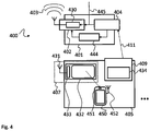
- Fig. 4 shows a block diagram of another communication system 400.
- the communication system 400 comprises a central data center 401 and one exemplary remote data node 405.
- the first RF downlink data interface 402 is a TV signal RF data interface and comprises an encoder 430. Further, the central data center 401 comprises a data synchronization unit 444.
- the encoder encodes the data 445 to be transmitted in the downlink in a TV RF signal 403 transmitted via the TV signal RF data interface 402.
- the data synchronization unit 444 synchronizes the data received via the first visible-light based uplink data interface 404 with the data 445 transmitted via the first RF downlink data interface 402. This is e.g. necessary, when a remote data node 405 requests specific data via the second visible-light based uplink data interface 409 from the central data center 401. The data synchronization unit 444 may then retrieve the requested data and provide said data to the first RF downlink data interface 402 for transmission to the remote data node 405. It is understood, that the encoder 430 and the data synchronization unit 444 may also be integrally formed in a single unit.
- the data synchronization unit 444 may e.g. provide the data 445 multiplexed for multiple remote data nodes 405 with respective node identifiers via the first RF downlink data interface 402.
- the data synchronization unit 444 may further provide the data 445 multiplexed for multiple remote data nodes 405 via at least two different TV channels.
- the second RF downlink data interface 407 is formed by an antenna 431 for receiving the RF signal 403 and a TV 432.
- the TV 432 serves as visible light communication downlink interface 432 that provides the data 445 transported in the RF signal 403 to a user device, here a smartphone 450, via visible light communication. Such visible light may be radiated by the screen of the TV 432.
- the decoder 433 in the second RF downlink data interface 407 may be the decoder of the TV 432 that also decodes the TV channels.
- the remote data node 405 further comprises a second visible-light based uplink data interface 409.
- the second visible-light based uplink data interface 409 further comprises an uplink data receiver 434.
- the uplink data receiver 434 may e.g. be a Wi-Fi access point or any other type of data receiver, like e.g. a Bluetooth or visible light data receiver.
- the data received via uplink data receiver 434 is then provided to the first visible-light based uplink data interface 404 via visible light 411 by the second visible-light based uplink data interface 409.
- the present invention provides a communication system 100, 200, 300, 400 for communicating data, the communication system 100, 200, 300, 400 comprising a central data center 101, 201, 301, 401, the central data center 101, 201, 301, 401 comprising a first RF downlink data interface 102, 402 for transmitting the data, and a first visible-light based uplink data interface 104, 204, 404, and a number of remote data nodes 105, 106, 205, 305, 306, 321, 322, 405, each data node comprising a second RF downlink data interface 107, 108, 407 configured to receive RF signals 103, 403 from the first RF downlink interface and a second visible-light based uplink data interface 109, 110, 409 configured to send visible light signals 111, 112, 211, 411 to the first visible-light based uplink data interface 104, 204, 404.
Landscapes
- Engineering & Computer Science (AREA)
- Physics & Mathematics (AREA)
- Electromagnetism (AREA)
- Computer Networks & Wireless Communication (AREA)
- Signal Processing (AREA)
- Computing Systems (AREA)
- Optical Communication System (AREA)
- Radio Relay Systems (AREA)
Abstract
Description
- The invention relates to a communication system.
- Although applicable in any application that requires data communication services, the present invention will mainly be described in conjunction with domestic data services.
- In modern society it is vital to provide data communication to as many people as possible. Usually data communication services are provided via RF based or cable based systems, like e.g. UMTS or LTE or cable internet.
- However, in remote locations often there is neither a LTE base station in reach nor any cable based internet access available. To provide internet access to such remote locations data may e.g. be transmitted via satellite. However, satellite based communication suffers a huge latency and is affected by bad weather conditions.
- Accordingly, there is a need for an improved data communication system.
- The present invention provides a communication system with the features of
claim 1. - Therefore it is provided:
- A communication system for communicating data, the communication system comprising a central data center, the central data center comprising a first RF downlink data interface for transmitting the data, and a first visible-light based uplink data interface, and a number, i.e. one or more, of remote data nodes, each remote data node comprising a second RF downlink data interface configured to receive RF signals from the first RF downlink interface and a second visible-light based uplink data interface configured to send signals to the first visible-light based uplink data interface.
- The present invention is based on the finding that RF signals are already present in today's public data infrastructure, like e.g. in TV broadcast signals and cell phone broadcast signals. Further, the present invention is based on the finding that visible light data communication may be used to transmit data at very high data rates over large distances.
- The present invention uses these findings and provides a hybrid data communication system that uses different physical channels for uplink and downlink data transmission.
- On the downlink side RF signals are provided from the first RF downlink data interface from a central data center to the second RF downlink data interfaces in the remote data nodes.
- In contrast to the RF based downlink, visible light data communication is used on the uplink channel, where the second visible-light based uplink data interfaces transmit data from the remote data nodes to the first visible-light based uplink interface in the central data center.
- The central data center may e.g. be coupled to the internet or comprise dedicated data sources, like e.g. file servers or the like, that provide the data to be transmitted in the downlink.
- The present invention therefore provides a wireless data service with a hybrid configuration, where the downlink channel does not share the same transmission medium with the uplink channel. Interference are reduced and sharing of bandwidth between the downlink and the uplink channel is therefore not necessary.
- Therefore a high bandwidth data service may be provided to a plurality of remote data nodes at the same time from a single central data center.
- Further embodiments of the present invention are subject of the further subclaims and of the following description, referring to the drawings.
- In an embodiment, the central data center may comprise a TV broadcast station.
- TV broadcast stations are usually positioned at exposed spots or locations to cover an area as large as possible with the RF signal that carries the TV program. Therefore, including the central data center with the TV broadcast station makes use of this exposed location to provide the data service to as many remote data nodes as possible with a single central data center.
- In an embodiment, the first RF downlink data interface may comprise a TV signal RF data interface.
- The present invention acknowledges that the RF signal emitted by the TV broadcast station is a RF signal that may be enhanced to carry an additional data stream that may carry a broadcast data stream or data that is requested by the remote data nodes via the uplink.
- In an embodiment, the TV signal RF data interface may comprise an encoder configured to encode data to be transmitted in the downlink in a TV signal transmitted via the TV signal RF data interface.
- The encoder may e.g. encode a data stream into the TV signal such that it may be decoded at the receiver side. Encoding means that the data may e.g. be added to the TV signals in the form of images. For example a single TV channel that is not used for image or video transmission may be used to transmit the signals via VLC (Visible Light Communication), or a dedicated section of a TV image may be used to encode and transmit the data via VLC e.g. by modulating the brightness of the image. Further, the TV image may be divided into different sections and e.g. the brightness of the single sections may be modulated, especially with such high frequencies that the modulation is not visible to the human eye to overlay the modulation over the TV channel contents.
- As an alternative the encoder may encode the data in signals of different TV channels at the same time such that the images transmitted for the different TV channels are not visibly modified. The data may e.g. be added to non-visible sections of the signals of the TV channels or the data may be distributed over the whole TV signal bandwidth such that the influence in every single TV channel is minimal.
- Furthermore, a specific multiuser broadcast encoding of multimedia pictures or videos can be realized at the TV broadcast station before sending the data to the users. In addition, specific data hiding or steganography methods can be utilized in a way not to spoil the TV broadcast multimedia content. If the whole image is utilized to broadcast downlink packets of the users without any data hiding, then the image is encoded to include all the data of multiple houses which can reach hundreds of numbers. For example, in the simplest case each pixel can include twenty four bits downlink data of a single house. In this manner, all the devices which can access the output image of TV a decoder can decode internet data, such as mobile phones with cameras capturing TV images even without any RF antenna. With such an approach, there is no need for an extra hardware or demodulator block for the downlink in comparison with hybrid structures utilizing TV RF white spaces in a cognitive manner. The TV decoder performs ordinarily by only generating output images without any intervention with the image data.
- Further, any other encoding scheme may be used that allows transmitting data embedded in the TV station RF signal. The user devices may then e.g. comprise decoders to demodulate a VLC data signal.
- In an embodiment, the second RF downlink data interface may comprise a decoder that is configured to decode the data embedded in the TV signal, and a visible light communication downlink interface configured to output the decoded data.
- The decoder may perform the reverse operation compared to the operations that are performed by the encoder. That means the decoder extracts the data that is embedded by the encoder in the TV signal from the TV signal for further processing by other elements of the communication system.
- The remote data nodes may e.g. be provided in or on buildings, like homes or industrial buildings. In such buildings usually some TV sets or TV screens will be present. Therefore, as an addition or as an alternative, the decoder and the visible light communication downlink interface may be arranged in a TV set that receives the TV signal and emits the data via the TV screen as visible light based communication signal. It is understood that in case that the data is encoded into the TV channel images as indicated above, the decoder is just the image decoder that is usually present in TV screens. No additional decoder is needed, since the data will be directly emitted by the TV screen when it shows the respective TV channel.
- However, a separate decoder unit may be provided that is independent of a TV set and may e.g. be a computer or the like.
- The visible light communication downlink interface may in one embodiment comprise a light source that is configured to emit the decoded data according to a predetermined visible light communication standard. The visible light communication downlink interface may e.g. induce the modulation signal into a light installation of a building, where all light sources then start emitting respective modulated light that carries the data.
- The visible light communication signal emitted by the visible light communication downlink interface may then e.g. be received by any mobile or static device, like e.g. smartphones, Tablet-PCs, or computers.
- In an embodiment, the second visible-light based uplink data interface may comprise an uplink data receiver configured to receive uplink data in the respective remote data node.
- The second visible-light based uplink data interface may be a kind of relay that receives uplink data from the devices, like e.g. smartphones, Tablet-PCs or computers, and transmits the data to the central data center. The uplink data receiver for receiving the uplink data may e.g. be a WIFI based data receiver or a visible light data receiver. It is understood, that in case that the uplink data receiver is a visible light data receiver, the uplink data receiver may use other frequencies than the visible light communication downlink interface.
- In an embodiment, the second visible-light based uplink data interface may comprise a visible light data communication source for modulating the uplink data and emitting a respective visible light signal including the modulated uplink data.
- The visible light data communication source may be any type of data source that is capable of directing modulated visible light to the first visible-light based uplink data interface. Such visible light data communication sources may e.g. be laser based light sources or LED based light sources.
- In an embodiment the visible light data communication source may e.g. comprise a LED panel of a predefined size, e.g. 1 m * 1 m or the like. Such a LED panel may e.g. be installed on the rooftop of a building or inside the building behind a window.
- Such LED or laser based visible light data communication sources may comprise a data encoder that modulates the light of the LEDs or laser according to the data received via the uplink data receiver.
- In an embodiment, the first visible-light based uplink data interface may comprise at least one camera sensor to receive the visible light emitted by the second visible-light based uplink data interfaces.
- Camera sensors, like e.g. CCD sensors are cheap and readily available electronic devices that can easily be integrated into the first visible-light based uplink data interface.
- In an embodiment, the first visible-light based uplink data interface may comprise at least one optical arrangement to focus the visible light emitted by the second visible-light based uplink data interfaces onto the camera sensor.
- The optical arrangement may comprise any type or combination of lenses, filters and other optical elements. The optical arrangement may be used to aim at the remote data nodes with the first visible-light based uplink data interface and therefore improve the reception of the visible light emitted by the second visible-light based uplink data interfaces.
- In an embodiment, the at least one optical arrangement may comprise at least one telescope, like e.g. a high focal length telescope.
- It is understood that the focal length of the telescope may be adapted to the distance between the central data center and the respective remote data nodes. With high focal length telescopes data may be transmitted over ranges of up to 50 km or more.
- The focal length may especially be arranged such that more than one remote data node, i.e. the light emitted by more than one remote data node, may be received with one telescope and camera sensor pair. This allows evaluating or receiving the data provided by a plurality of remote data nodes at the same time with a single camera sensor.
- In an embodiment, the central data center may comprise a data synchronization unit configured to synchronize the data received via the first visible-light based uplink data interface with the data transmitted via the first RF downlink data interface.
- Data may be provided to the remote data nodes in the form of a predefined data stream. For example weather data, news or the like may be provided by the central data center to all remote data nodes.
- However, a remote data node may want to request specific data, e.g. from the internet. This request may be transmitted to the central data center via the respective second visible-light based uplink data interface and the first visible-light based uplink data interface.
- The data synchronization unit will then retrieve the requested data from the respective source, e.g. a server on the internet, and provide the data together with respective synchronization information e.g. to the encoder of the first RF downlink data interface. The synchronization information refers to information that is included in the data stream and allows the receiving remote data node to identify that the specific data is the data it had requested.
- In an embodiment, the data synchronization unit may further be configured to provide multiplexed data for multiple remote data nodes with respective node identifiers via the first RF downlink data interface.
- The data synchronization unit may not only include data for a single one of the remote data nodes in the downlink data stream. Instead the data synchronization unit may at the same time provide different remote data nodes with respective data.
- When more than one remote data node requests data e.g. from the internet the remote data nodes, e.g. the visible light data communication sources, may include a node identifier in the request. The node identifier is also known to the decoder in the second RF downlink data interface or to the device that receives the data from the second RF downlink data interface at the respective remote data node to extract the respective data.
- The data synchronization unit may then request the data from the respective sources and multiplex the data in the downlink data channel and include the node identifiers accordingly.
- In another embodiment, the data synchronization unit may be configured to provide multiplexed data for multiple remote data nodes via at least two different TV channels.
- The data synchronization unit may e.g. split the data for different remote data nodes over different TV channels, while a single TV channel may still be used to provide data to more than one remote data node. If e.g. four data nodes receive data this data may be transmitted via two TV channels, each TV channel carrying data for two remote data nodes. It is also possible that one TV channel carries data for three data nodes and the other TV channel carries data for one data node depending on the required bandwidth.
- In a further embodiment, the data synchronization unit may be configured to provide in the RF signals transmitted to the second RF downlink data interfaces information about the TV channel that carries data for a specific remote data node.
- This allows the remote data nodes, e.g. the second RF downlink data interfaces in the remote data nodes to automatically select the respective TV channels that carry the relevant data.
- For a more complete understanding of the present invention and advantages thereof, reference is now made to the following description taken in conjunction with the accompanying drawings. The invention is explained in more detail below using exemplary embodiments which are specified in the schematic figures of the drawings, in which:
-
Fig. 1 shows a block diagram of an embodiment of a communication system according to the present invention; -
Fig. 2 shows a block diagram of another embodiment of a communication system according to the present invention; -
Fig. 3 shows a block diagram of another embodiment of a communication system according to the present invention; and -
Fig. 4 shows a block diagram of another embodiment of a communication system according to the present invention. - In the figures like reference signs denote like elements unless stated otherwise.
-
Fig. 1 shows a block diagram ofcommunication system 100. Thecommunication system 100 comprises acentral data center 101 and tworemote data nodes remote data nodes - The
central data center 101 comprises a first RFdownlink data interface 102 and a first visible-light baseduplink data interface 104. Theremote data nodes downlink data interface uplink data interface - The
central data center 101 may e.g. be a TV broadcast station that emits RF signals 103, like e.g. UHF TV signals. Therefore, the first RFdownlink data interface 102 may also be a TV signal RF data interface, over which the first RFdownlink data interface 102 provides TV programs to the area surrounding thecentral data center 101. - Alternatively, the
central data center 101 may e.g. be a cell phone base station that emits RF signals 103, like e.g. LTE data signals. Thecentral data center 101 may e.g. be a cell phone base station. - The first RF
downlink data interface 102 in any case uses an already present RF interface to provideadditional data 145 in thedownlink RF signal 103. In case of a TV channel RF signal 103 the first RFdownlink data interface 102 may especially encode thedata 145 in thedownlink RF signal 103 in the image data, i.e. without additional data side channels or the like, as VLC. Thedata 145 may e.g. be provided to thecentral data center 101 via the internet or thecentral data center 101 may comprise respective data sources. - In the
remote data nodes RF signal 103 and extract thedata 145. If theremote data nodes central data center 101 in return, they transmit such uplink data via the second visible-light based uplink data interfaces 109, 110 viavisible light central data center 101. In thecentral data center 101 thevisible light visible light -
Fig. 2 shows a block diagram of anothercommunication system 200. Thecommunication system 200 shows details of the first visible-light based uplink data interface 204 and of the second visible-light based uplink data interfaces (not separately referenced). - The central data center 201 of the
communication system 200 comprises a first visible-light based uplink data interface 204 with acamera sensor 213 and alens 214 in front of thecamera sensor 213. With the lens the light from a specific region is focused onto thecamera sensor 213. This specific region may also be called acell 217 that is served with thecamera sensor 213. - Just exemplarily one
remote data node 205 is shown in front of thelens 214, while more remote data nodes are hinted at by three dots. The distance between thelens 214 and theremote data node 205 in reality may be as large as tens of kilometers, like e.g. 50 km. This also makes it obvious that the first RF downlink data interface and the first visible-light based uplink data interface 104 may be provided separately since most RF communication standards will not cover a distance of 50 km. - The
remote data node 205 may e.g. be a house or another building, like e.g. an industrial building. On top of the house or building a visible light data communication source 215 may be provided. The visible light data communication source 215 may e.g. comprise a matrix ofLEDs 216, of which only four are shown. It is understood that the matrix may be adapted e.g. to the distance between the central data center 201 and theremote data node 205. The visible light data communication source 215 may e.g. be 10 cm * 10 cm or up to 2 m * 2 m or the like. Non-square sizes, like e.g. 1 m * 2 m, are also possible. Laser-based visible light data communication sources 215 are also possible. - It can be seen that the
camera sensor 213 comprises a plurality of pixels (not separately referenced). Thecamera sensor 213 or any other component of the first visible-light based uplink data interface 204 may e.g. be calibrated to know which of the pixels represent which one of theremote data nodes 205. One pixel must not necessarily represent oneremote data node 205. Instead a group of pixels may also represent a singleremote data node 205. In addition or as an alternative the differentremote data nodes 205 may transmit data with light at different wavelengths, e.g. with red, blue and green light, and/or different modulation frequencies to differentiate the singleremote data nodes 205. - It is understood that the
lens 214 is just exemplarily shown instead of any other optical arrangement, like e.g. telescopes or the like. Further, a plurality of optical arrangements may be provided with overlapping orseparate cells 217. Multiple optical arrangements can e.g. focus ontoremote data nodes 205 in the same direction but in different distances to the central data center 201. Further, every optical arrangement may also comprise adedicated camera sensor 213. - It is clear that the first visible-light based uplink data interface 204 may comprise any further element that is necessary to demodulate or decode the visible light communication received via light 211 from the
remote data node 205. Such elements may e.g. be signal processors, general purpose processors, FPGAs or the like and any other, e.g. discrete electronic or electric, element, that is necessary. -
Fig. 3 shows a block diagram of another communication system 300. The communication system 300 comprises acentral data center 301 that may e.g. be aTV broadcast station 301. In the central data center 301 a plurality of first visible-light based uplink data interfaces are provided (not explicitly referenced) to cover a 360° area around thecentral data center 301. Every first visible-light based uplink data interface covers a specific sector or cell of the 360° circle. - For sake of clarity only the elements of two of the
cells - Every cell may cover an area with a plurality of
remote data nodes remote data nodes cell 317 and tworemote data nodes cell 325 and more remote data nodes are hinted at by three dots. - In the
central data center 301 for everycell optical element camera sensor data communication sources 315, 318,323,324 will be received by thecamera sensor cell data communication sources - Not shown are the elements of the first RF downlink data interface of the
central data center 301. It is understood, that especially in case that thecentral data center 301 is a TV broadcast station, the elements of the first RF downlink data interface are provided in thecentral data center 301 as TV RF interfaces and provide the downlink data channel to theremote data nodes - The further cells of the communication system 300 are indicated by dotted lines and it can be seen that with the arrangement of the communication system 300 a 360° area around the
central data center 301 can be provided with data services via RF signals and visible light according to the present invention.. -
Fig. 4 shows a block diagram of another communication system 400. The communication system 400 comprises acentral data center 401 and one exemplaryremote data node 405. - In the
central data center 401 the first RFdownlink data interface 402 is a TV signal RF data interface and comprises anencoder 430. Further, thecentral data center 401 comprises adata synchronization unit 444. The encoder encodes thedata 445 to be transmitted in the downlink in aTV RF signal 403 transmitted via the TV signal RF data interface 402. - The
data synchronization unit 444 synchronizes the data received via the first visible-light based uplink data interface 404 with thedata 445 transmitted via the first RFdownlink data interface 402. This is e.g. necessary, when aremote data node 405 requests specific data via the second visible-light based uplink data interface 409 from thecentral data center 401. Thedata synchronization unit 444 may then retrieve the requested data and provide said data to the first RFdownlink data interface 402 for transmission to theremote data node 405. It is understood, that theencoder 430 and thedata synchronization unit 444 may also be integrally formed in a single unit. - The
data synchronization unit 444 may e.g. provide thedata 445 multiplexed for multipleremote data nodes 405 with respective node identifiers via the first RFdownlink data interface 402. Thedata synchronization unit 444 may further provide thedata 445 multiplexed for multipleremote data nodes 405 via at least two different TV channels. - In the
remote data node 405 the second RFdownlink data interface 407 is formed by anantenna 431 for receiving theRF signal 403 and aTV 432. TheTV 432 serves as visible lightcommunication downlink interface 432 that provides thedata 445 transported in the RF signal 403 to a user device, here asmartphone 450, via visible light communication. Such visible light may be radiated by the screen of theTV 432. Thedecoder 433 in the second RFdownlink data interface 407 may be the decoder of theTV 432 that also decodes the TV channels. - The
remote data node 405 further comprises a second visible-light baseduplink data interface 409. The second visible-light based uplink data interface 409 further comprises anuplink data receiver 434. Theuplink data receiver 434 may e.g. be a Wi-Fi access point or any other type of data receiver, like e.g. a Bluetooth or visible light data receiver. The data received viauplink data receiver 434 is then provided to the first visible-light based uplink data interface 404 viavisible light 411 by the second visible-light baseduplink data interface 409. - Although specific embodiments have been illustrated and described herein, it will be appreciated by those of ordinary skill in the art that a variety of alternate and/or equivalent implementations exist. It should be appreciated that the exemplary embodiment or exemplary embodiments are only examples, and are not intended to limit the scope, applicability, or configuration in any way. Rather, the foregoing summary and detailed description will provide those skilled in the art with a convenient road map for implementing at least one exemplary embodiment, it being understood that various changes may be made in the function and arrangement of elements described in an exemplary embodiment without departing from the scope as set forth in the appended claims and their legal equivalents. Generally, this application is intended to cover any adaptations or variations of the specific embodiments discussed herein.
- Thus, the present invention provides a
communication system communication system central data center central data center downlink data interface uplink data interface remote data nodes downlink data interface RF signals uplink data interface uplink data interface -
- 100, 200, 300, 400
- communication system
- 101, 201, 301, 401
- central data center
- 102, 402
- first RF downlink data interface
- 103, 403
- RF signals
- 104, 204, 404
- first visible-light based uplink data interface
- 105, 106, 205, 305, 306, 321, 322, 405
- remote data nodes
- 107, 108, 407
- second RF downlink data interface
- 109, 110, 409
- second visible-light based uplink data interface
- 111, 112, 211, 411
- visible light signal
- 213, 313, 319
- camera sensor
- 214, 314, 320
- optical arrangement
- 215, 315, 318, 323, 324
- visible light data communication source
- 216
- LED
- 217, 317, 325
- Cell
- 430
- encoder
- 431
- antenna
- 432
- visible light communication downlink interface
- 433
- decoder
- 434
- uplink data receiver
- 444
- data synchronization unit
- 145, 445
- data
- 450
- Smartphone
- 451
- camera
- 452
- WIFI Interface
Claims (14)
- Communication system (100, 200, 300, 400) for communicating data (145, 445), the communication system (100, 200, 300, 400) comprising:a central data center (101, 201, 301, 401), the central data center (101, 201, 301, 401) comprising a first RF downlink data interface (102, 402) for transmitting the data (145, 445), and a first visible-light based uplink data interface (104, 204, 404), anda number of remote data nodes (105, 106, 205, 305, 306, 321, 322, 405), each remote data node comprising a second RF downlink data interface (107, 108, 407) configured to receive RF signals (103, 403) from the first RF downlink interface and a second visible-light based uplink data interface (109, 110, 409) configured to send visible light signals (111, 112, 211, 411) to the first visible-light based uplink data interface (104, 204, 404).
- Communication system (100, 200, 300, 400) according to claim 1, wherein the central data center (101, 201, 301, 401) comprises a TV broadcast station.
- Communication system (100, 200, 300, 400) according to claim 2, wherein the first RF downlink data interface (102, 402) comprises a TV signal RF data interface.
- Communication system (100, 200, 300, 400) according to claim 3, wherein the TV signal RF data interface comprises an encoder (430) configured to encode the data (145, 445) to be transmitted in the downlink in a TV signal transmitted via the TV signal RF data interface.
- Communication system (100, 200, 300, 400) according to claim 4, wherein the second RF downlink data interface (107, 108, 407) comprises a decoder (433) that is configured to decode the data (145, 445) embedded in the TV signal, and a visible light communication downlink interface (432) configured to output the decoded data (145, 445).
- Communication system (100, 200, 300, 400) according to any one of the preceding claims, wherein the second visible-light based uplink data interface (109, 110, 409) comprises an uplink data receiver (434) configured to receive uplink data in the respective remote data node.
- Communication system (100, 200, 300, 400) according to claim 6, wherein the second visible-light based uplink data interface (109, 110, 409) comprises a visible light data communication source (215, 315, 318, 323, 324) for modulating the uplink data and emitting a respective visible light signal (111, 112, 211, 411) including the modulated uplink data.
- Communication system (100, 200, 300, 400) according to any one of the preceding claims, wherein the first visible-light based uplink data interface (104, 204, 404) comprises at least one camera sensor (213, 313, 319) to receive the visible light emitted by the second visible-light based uplink data interfaces (109, 110, 409).
- Communication system (100, 200, 300, 400) according to claim 8, wherein the first visible-light based uplink data interface (104, 204, 404) comprises at least one optical arrangement (214, 314, 320) to focus the visible light emitted by the second visible-light based uplink data interfaces (109, 110, 409) onto the camera sensor (213, 313, 319).
- Communication system (100, 200, 300, 400) according to claim 9, wherein the at least one optical arrangement (214, 314, 320) comprises at least one telescope.
- Communication system (100, 200, 300, 400) according to any one of the preceding claims, wherein the central data center (101, 201, 301, 401) comprises a data synchronization unit (444) configured to synchronize the data received via the first visible-light based uplink data interface (104, 204, 404) with the data (145, 445) transmitted via the first RF downlink data interface (102, 402).
- Communication system (100, 200, 300, 400) according to claim 11, wherein the data synchronization unit (444) is further configured to provide the data (145, 445) multiplexed for multiple remote data nodes (105, 106, 205, 305, 306, 321, 322, 405) with respective node identifiers via the first RF downlink data interface (102, 402).
- Communication system (100, 200, 300, 400) according to any one of claims 11 or 12, wherein the data synchronization unit (444) is configured to provide the data (145, 445) multiplexed for multiple remote data nodes (105, 106, 205, 305, 306, 321, 322, 405) via at least two different TV channels.
- Communication system (100, 200, 300, 400) according to claim 13, wherein the data synchronization unit (444) is configured to provide in the RF signals (103, 403) transmitted to the second RF downlink data interfaces (107, 108, 407) information about the TV channel that carries data (145, 445) for a specific remote data node.
Priority Applications (2)
| Application Number | Priority Date | Filing Date | Title |
|---|---|---|---|
| EP17175972.3A EP3416305B1 (en) | 2017-06-14 | 2017-06-14 | Communication system |
| TR2017/09272A TR201709272A2 (en) | 2017-06-14 | 2017-06-21 | COMMUNICATION SYSTEM |
Applications Claiming Priority (1)
| Application Number | Priority Date | Filing Date | Title |
|---|---|---|---|
| EP17175972.3A EP3416305B1 (en) | 2017-06-14 | 2017-06-14 | Communication system |
Publications (2)
| Publication Number | Publication Date |
|---|---|
| EP3416305A1 true EP3416305A1 (en) | 2018-12-19 |
| EP3416305B1 EP3416305B1 (en) | 2020-02-26 |
Family
ID=59070489
Family Applications (1)
| Application Number | Title | Priority Date | Filing Date |
|---|---|---|---|
| EP17175972.3A Active EP3416305B1 (en) | 2017-06-14 | 2017-06-14 | Communication system |
Country Status (2)
| Country | Link |
|---|---|
| EP (1) | EP3416305B1 (en) |
| TR (1) | TR201709272A2 (en) |
Cited By (2)
| Publication number | Priority date | Publication date | Assignee | Title |
|---|---|---|---|---|
| WO2021115611A1 (en) * | 2019-12-13 | 2021-06-17 | Telefonaktiebolaget Lm Ericsson (Publ) | Access network and wireless device |
| CN113766522A (en) * | 2021-09-30 | 2021-12-07 | 中国电信股份有限公司 | VLC-RF heterogeneous network deployment method, device, equipment and medium based on room division system |
Citations (6)
| Publication number | Priority date | Publication date | Assignee | Title |
|---|---|---|---|---|
| US20110044218A1 (en) * | 2009-08-21 | 2011-02-24 | Interdigital Patent Holdings, Inc. | Method and apparatus for a multi-radio access technology layer for splitting downlink-uplink over different radio access technologies |
| US20110063510A1 (en) * | 2009-09-16 | 2011-03-17 | Samsung Electronics Co., Ltd. | Method and apparatus for providing additional information through display |
| US7920794B1 (en) * | 2007-01-05 | 2011-04-05 | Lockheed Martin Corporation | Free space optical communication |
| US20130183042A1 (en) * | 2011-09-13 | 2013-07-18 | David J. Knapp | System and Method of Extending the Communication Range in a Visible Light Communication System |
| WO2013190410A1 (en) * | 2012-06-21 | 2013-12-27 | Koninklijke Philips N.V. | Hybrid rf – optical link for mobile communication devices |
| US20140029952A1 (en) * | 2011-03-15 | 2014-01-30 | Huawei Technologies Co., Ltd. | Data transmission method and related device and system |
-
2017
- 2017-06-14 EP EP17175972.3A patent/EP3416305B1/en active Active
- 2017-06-21 TR TR2017/09272A patent/TR201709272A2/en unknown
Patent Citations (6)
| Publication number | Priority date | Publication date | Assignee | Title |
|---|---|---|---|---|
| US7920794B1 (en) * | 2007-01-05 | 2011-04-05 | Lockheed Martin Corporation | Free space optical communication |
| US20110044218A1 (en) * | 2009-08-21 | 2011-02-24 | Interdigital Patent Holdings, Inc. | Method and apparatus for a multi-radio access technology layer for splitting downlink-uplink over different radio access technologies |
| US20110063510A1 (en) * | 2009-09-16 | 2011-03-17 | Samsung Electronics Co., Ltd. | Method and apparatus for providing additional information through display |
| US20140029952A1 (en) * | 2011-03-15 | 2014-01-30 | Huawei Technologies Co., Ltd. | Data transmission method and related device and system |
| US20130183042A1 (en) * | 2011-09-13 | 2013-07-18 | David J. Knapp | System and Method of Extending the Communication Range in a Visible Light Communication System |
| WO2013190410A1 (en) * | 2012-06-21 | 2013-12-27 | Koninklijke Philips N.V. | Hybrid rf – optical link for mobile communication devices |
Non-Patent Citations (2)
| Title |
|---|
| LEITGEB E ET AL: "Combination of Free Space Optics (FSO) and RF for different wireless application scenarios", 2015 9TH EUROPEAN CONFERENCE ON ANTENNAS AND PROPAGATION (EUCAP), EURAAP, 13 April 2015 (2015-04-13), pages 1 - 4, XP033213178 * |
| MANDL P ET AL: "Hybrid systems using DVB-T, WLAN and FSO to connect peripheral regions with broadband Internet services", CAD SYSTEMS IN MICROELECTRONICS, 2009. CADSM 2009. 10TH INTERNATIONAL CONFERENCE - THE EXPERIENCE OF DESIGNING AND APPLICATION OF, IEEE, PISCATAWAY, NJ, USA, 8 June 2009 (2009-06-08), pages 67 - 71, XP031514087, ISBN: 978-953-184-130-6 * |
Cited By (4)
| Publication number | Priority date | Publication date | Assignee | Title |
|---|---|---|---|---|
| WO2021115611A1 (en) * | 2019-12-13 | 2021-06-17 | Telefonaktiebolaget Lm Ericsson (Publ) | Access network and wireless device |
| US12308880B2 (en) | 2019-12-13 | 2025-05-20 | Telefonaktiebolaget Lm Ericsson (Publ) | Access network and wireless device |
| CN113766522A (en) * | 2021-09-30 | 2021-12-07 | 中国电信股份有限公司 | VLC-RF heterogeneous network deployment method, device, equipment and medium based on room division system |
| CN113766522B (en) * | 2021-09-30 | 2022-08-02 | 中国电信股份有限公司 | VLC-RF heterogeneous network deployment method, device, equipment and medium based on room division system |
Also Published As
| Publication number | Publication date |
|---|---|
| TR201709272A2 (en) | 2019-01-21 |
| EP3416305B1 (en) | 2020-02-26 |
Similar Documents
| Publication | Publication Date | Title |
|---|---|---|
| Saha et al. | Survey on optical camera communications: challenges and opportunities | |
| US10455006B2 (en) | Signal generating method, signal generating unit, and non-transitory recording medium storing computer program | |
| US10389446B2 (en) | Reproduction method for reproducing contents | |
| US10187147B2 (en) | Signal decoding method, signal decoding device, and non-transitory computer-readable recording medium storing program | |
| US9998220B2 (en) | Transmitting method, transmitting apparatus, and program | |
| Aoyama et al. | Visible light communication using a conventional image sensor | |
| US11695477B2 (en) | Spatial optical wireless communication system | |
| US10166917B2 (en) | Transmission of uncompressed video in cellular networks | |
| US20160352422A1 (en) | Multi-functional smart led systems with visible light communication and ip-based radiofrequency connectivity | |
| US11974078B2 (en) | Digital signage by optical communication and supplemental downlink device and method using LED illumination | |
| US20250105919A1 (en) | Reception device and reception method | |
| JP2024019243A (en) | transmitting device | |
| KR102294353B1 (en) | Image display apparatus and video wall including the same | |
| US11012844B2 (en) | Peer-to-peer emergency communication using public broadcasting | |
| KR20170084709A (en) | Image sensor communication system based on dimmable M-PSK | |
| EP3416305B1 (en) | Communication system | |
| EP3236598A1 (en) | Transmission method, transmission device and program | |
| US9130674B2 (en) | Coded-light detection system including a camera, light sensor and augmented information display | |
| KR20130065929A (en) | Satellite broadcasting system and method | |
| CN106411402A (en) | Video on demand system based on visible light communication technology | |
| Le et al. | Effect of blur Gaussian in MIMO optical camera communications | |
| KR101674961B1 (en) | Digital device and method for obtaining color image thereof | |
| US10165312B2 (en) | Over-the-air television gap filler using television-white-space channels via wireless local area networks | |
| Shatz et al. | Demonstration of augmented-reality optical narrowcasting | |
| KR101260637B1 (en) | High-definition cctv system having multiplex transferring device and method for operating thereof |
Legal Events
| Date | Code | Title | Description |
|---|---|---|---|
| PUAI | Public reference made under article 153(3) epc to a published international application that has entered the european phase |
Free format text: ORIGINAL CODE: 0009012 |
|
| STAA | Information on the status of an ep patent application or granted ep patent |
Free format text: STATUS: THE APPLICATION HAS BEEN PUBLISHED |
|
| AK | Designated contracting states |
Kind code of ref document: A1 Designated state(s): AL AT BE BG CH CY CZ DE DK EE ES FI FR GB GR HR HU IE IS IT LI LT LU LV MC MK MT NL NO PL PT RO RS SE SI SK SM TR |
|
| AX | Request for extension of the european patent |
Extension state: BA ME |
|
| STAA | Information on the status of an ep patent application or granted ep patent |
Free format text: STATUS: REQUEST FOR EXAMINATION WAS MADE |
|
| 17P | Request for examination filed |
Effective date: 20190611 |
|
| RBV | Designated contracting states (corrected) |
Designated state(s): AL AT BE BG CH CY CZ DE DK EE ES FI FR GB GR HR HU IE IS IT LI LT LU LV MC MK MT NL NO PL PT RO RS SE SI SK SM TR |
|
| GRAP | Despatch of communication of intention to grant a patent |
Free format text: ORIGINAL CODE: EPIDOSNIGR1 |
|
| STAA | Information on the status of an ep patent application or granted ep patent |
Free format text: STATUS: GRANT OF PATENT IS INTENDED |
|
| INTG | Intention to grant announced |
Effective date: 20190927 |
|
| GRAS | Grant fee paid |
Free format text: ORIGINAL CODE: EPIDOSNIGR3 |
|
| GRAA | (expected) grant |
Free format text: ORIGINAL CODE: 0009210 |
|
| STAA | Information on the status of an ep patent application or granted ep patent |
Free format text: STATUS: THE PATENT HAS BEEN GRANTED |
|
| AK | Designated contracting states |
Kind code of ref document: B1 Designated state(s): AL AT BE BG CH CY CZ DE DK EE ES FI FR GB GR HR HU IE IS IT LI LT LU LV MC MK MT NL NO PL PT RO RS SE SI SK SM TR |
|
| REG | Reference to a national code |
Ref country code: GB Ref legal event code: FG4D |
|
| REG | Reference to a national code |
Ref country code: CH Ref legal event code: EP |
|
| REG | Reference to a national code |
Ref country code: DE Ref legal event code: R096 Ref document number: 602017012146 Country of ref document: DE |
|
| REG | Reference to a national code |
Ref country code: AT Ref legal event code: REF Ref document number: 1238931 Country of ref document: AT Kind code of ref document: T Effective date: 20200315 |
|
| REG | Reference to a national code |
Ref country code: IE Ref legal event code: FG4D |
|
| PG25 | Lapsed in a contracting state [announced via postgrant information from national office to epo] |
Ref country code: FI Free format text: LAPSE BECAUSE OF FAILURE TO SUBMIT A TRANSLATION OF THE DESCRIPTION OR TO PAY THE FEE WITHIN THE PRESCRIBED TIME-LIMIT Effective date: 20200226 Ref country code: RS Free format text: LAPSE BECAUSE OF FAILURE TO SUBMIT A TRANSLATION OF THE DESCRIPTION OR TO PAY THE FEE WITHIN THE PRESCRIBED TIME-LIMIT Effective date: 20200226 Ref country code: NO Free format text: LAPSE BECAUSE OF FAILURE TO SUBMIT A TRANSLATION OF THE DESCRIPTION OR TO PAY THE FEE WITHIN THE PRESCRIBED TIME-LIMIT Effective date: 20200526 |
|
| REG | Reference to a national code |
Ref country code: NL Ref legal event code: MP Effective date: 20200226 |
|
| REG | Reference to a national code |
Ref country code: LT Ref legal event code: MG4D |
|
| PG25 | Lapsed in a contracting state [announced via postgrant information from national office to epo] |
Ref country code: BG Free format text: LAPSE BECAUSE OF FAILURE TO SUBMIT A TRANSLATION OF THE DESCRIPTION OR TO PAY THE FEE WITHIN THE PRESCRIBED TIME-LIMIT Effective date: 20200526 Ref country code: IS Free format text: LAPSE BECAUSE OF FAILURE TO SUBMIT A TRANSLATION OF THE DESCRIPTION OR TO PAY THE FEE WITHIN THE PRESCRIBED TIME-LIMIT Effective date: 20200626 Ref country code: LV Free format text: LAPSE BECAUSE OF FAILURE TO SUBMIT A TRANSLATION OF THE DESCRIPTION OR TO PAY THE FEE WITHIN THE PRESCRIBED TIME-LIMIT Effective date: 20200226 Ref country code: SE Free format text: LAPSE BECAUSE OF FAILURE TO SUBMIT A TRANSLATION OF THE DESCRIPTION OR TO PAY THE FEE WITHIN THE PRESCRIBED TIME-LIMIT Effective date: 20200226 Ref country code: GR Free format text: LAPSE BECAUSE OF FAILURE TO SUBMIT A TRANSLATION OF THE DESCRIPTION OR TO PAY THE FEE WITHIN THE PRESCRIBED TIME-LIMIT Effective date: 20200527 Ref country code: HR Free format text: LAPSE BECAUSE OF FAILURE TO SUBMIT A TRANSLATION OF THE DESCRIPTION OR TO PAY THE FEE WITHIN THE PRESCRIBED TIME-LIMIT Effective date: 20200226 |
|
| PG25 | Lapsed in a contracting state [announced via postgrant information from national office to epo] |
Ref country code: NL Free format text: LAPSE BECAUSE OF FAILURE TO SUBMIT A TRANSLATION OF THE DESCRIPTION OR TO PAY THE FEE WITHIN THE PRESCRIBED TIME-LIMIT Effective date: 20200226 |
|
| PG25 | Lapsed in a contracting state [announced via postgrant information from national office to epo] |
Ref country code: PT Free format text: LAPSE BECAUSE OF FAILURE TO SUBMIT A TRANSLATION OF THE DESCRIPTION OR TO PAY THE FEE WITHIN THE PRESCRIBED TIME-LIMIT Effective date: 20200719 Ref country code: EE Free format text: LAPSE BECAUSE OF FAILURE TO SUBMIT A TRANSLATION OF THE DESCRIPTION OR TO PAY THE FEE WITHIN THE PRESCRIBED TIME-LIMIT Effective date: 20200226 Ref country code: DK Free format text: LAPSE BECAUSE OF FAILURE TO SUBMIT A TRANSLATION OF THE DESCRIPTION OR TO PAY THE FEE WITHIN THE PRESCRIBED TIME-LIMIT Effective date: 20200226 Ref country code: SK Free format text: LAPSE BECAUSE OF FAILURE TO SUBMIT A TRANSLATION OF THE DESCRIPTION OR TO PAY THE FEE WITHIN THE PRESCRIBED TIME-LIMIT Effective date: 20200226 Ref country code: RO Free format text: LAPSE BECAUSE OF FAILURE TO SUBMIT A TRANSLATION OF THE DESCRIPTION OR TO PAY THE FEE WITHIN THE PRESCRIBED TIME-LIMIT Effective date: 20200226 Ref country code: SM Free format text: LAPSE BECAUSE OF FAILURE TO SUBMIT A TRANSLATION OF THE DESCRIPTION OR TO PAY THE FEE WITHIN THE PRESCRIBED TIME-LIMIT Effective date: 20200226 Ref country code: LT Free format text: LAPSE BECAUSE OF FAILURE TO SUBMIT A TRANSLATION OF THE DESCRIPTION OR TO PAY THE FEE WITHIN THE PRESCRIBED TIME-LIMIT Effective date: 20200226 Ref country code: CZ Free format text: LAPSE BECAUSE OF FAILURE TO SUBMIT A TRANSLATION OF THE DESCRIPTION OR TO PAY THE FEE WITHIN THE PRESCRIBED TIME-LIMIT Effective date: 20200226 Ref country code: ES Free format text: LAPSE BECAUSE OF FAILURE TO SUBMIT A TRANSLATION OF THE DESCRIPTION OR TO PAY THE FEE WITHIN THE PRESCRIBED TIME-LIMIT Effective date: 20200226 |
|
| REG | Reference to a national code |
Ref country code: AT Ref legal event code: MK05 Ref document number: 1238931 Country of ref document: AT Kind code of ref document: T Effective date: 20200226 |
|
| REG | Reference to a national code |
Ref country code: DE Ref legal event code: R097 Ref document number: 602017012146 Country of ref document: DE |
|
| PLBE | No opposition filed within time limit |
Free format text: ORIGINAL CODE: 0009261 |
|
| STAA | Information on the status of an ep patent application or granted ep patent |
Free format text: STATUS: NO OPPOSITION FILED WITHIN TIME LIMIT |
|
| PG25 | Lapsed in a contracting state [announced via postgrant information from national office to epo] |
Ref country code: IT Free format text: LAPSE BECAUSE OF FAILURE TO SUBMIT A TRANSLATION OF THE DESCRIPTION OR TO PAY THE FEE WITHIN THE PRESCRIBED TIME-LIMIT Effective date: 20200226 Ref country code: AT Free format text: LAPSE BECAUSE OF FAILURE TO SUBMIT A TRANSLATION OF THE DESCRIPTION OR TO PAY THE FEE WITHIN THE PRESCRIBED TIME-LIMIT Effective date: 20200226 Ref country code: MC Free format text: LAPSE BECAUSE OF FAILURE TO SUBMIT A TRANSLATION OF THE DESCRIPTION OR TO PAY THE FEE WITHIN THE PRESCRIBED TIME-LIMIT Effective date: 20200226 |
|
| REG | Reference to a national code |
Ref country code: CH Ref legal event code: PL |
|
| 26N | No opposition filed |
Effective date: 20201127 |
|
| PG25 | Lapsed in a contracting state [announced via postgrant information from national office to epo] |
Ref country code: SI Free format text: LAPSE BECAUSE OF FAILURE TO SUBMIT A TRANSLATION OF THE DESCRIPTION OR TO PAY THE FEE WITHIN THE PRESCRIBED TIME-LIMIT Effective date: 20200226 Ref country code: PL Free format text: LAPSE BECAUSE OF FAILURE TO SUBMIT A TRANSLATION OF THE DESCRIPTION OR TO PAY THE FEE WITHIN THE PRESCRIBED TIME-LIMIT Effective date: 20200226 |
|
| PG25 | Lapsed in a contracting state [announced via postgrant information from national office to epo] |
Ref country code: LU Free format text: LAPSE BECAUSE OF NON-PAYMENT OF DUE FEES Effective date: 20200614 |
|
| REG | Reference to a national code |
Ref country code: BE Ref legal event code: MM Effective date: 20200630 |
|
| PG25 | Lapsed in a contracting state [announced via postgrant information from national office to epo] |
Ref country code: IE Free format text: LAPSE BECAUSE OF NON-PAYMENT OF DUE FEES Effective date: 20200614 Ref country code: FR Free format text: LAPSE BECAUSE OF NON-PAYMENT OF DUE FEES Effective date: 20200630 Ref country code: CH Free format text: LAPSE BECAUSE OF NON-PAYMENT OF DUE FEES Effective date: 20200630 Ref country code: LI Free format text: LAPSE BECAUSE OF NON-PAYMENT OF DUE FEES Effective date: 20200630 |
|
| PG25 | Lapsed in a contracting state [announced via postgrant information from national office to epo] |
Ref country code: BE Free format text: LAPSE BECAUSE OF NON-PAYMENT OF DUE FEES Effective date: 20200630 |
|
| PG25 | Lapsed in a contracting state [announced via postgrant information from national office to epo] |
Ref country code: MT Free format text: LAPSE BECAUSE OF FAILURE TO SUBMIT A TRANSLATION OF THE DESCRIPTION OR TO PAY THE FEE WITHIN THE PRESCRIBED TIME-LIMIT Effective date: 20200226 Ref country code: CY Free format text: LAPSE BECAUSE OF FAILURE TO SUBMIT A TRANSLATION OF THE DESCRIPTION OR TO PAY THE FEE WITHIN THE PRESCRIBED TIME-LIMIT Effective date: 20200226 |
|
| PG25 | Lapsed in a contracting state [announced via postgrant information from national office to epo] |
Ref country code: MK Free format text: LAPSE BECAUSE OF FAILURE TO SUBMIT A TRANSLATION OF THE DESCRIPTION OR TO PAY THE FEE WITHIN THE PRESCRIBED TIME-LIMIT Effective date: 20200226 Ref country code: AL Free format text: LAPSE BECAUSE OF FAILURE TO SUBMIT A TRANSLATION OF THE DESCRIPTION OR TO PAY THE FEE WITHIN THE PRESCRIBED TIME-LIMIT Effective date: 20200226 |
|
| PGFP | Annual fee paid to national office [announced via postgrant information from national office to epo] |
Ref country code: DE Payment date: 20250618 Year of fee payment: 9 |
|
| PGFP | Annual fee paid to national office [announced via postgrant information from national office to epo] |
Ref country code: GB Payment date: 20260629 Year of fee payment: 10 |
|
| PGFP | Annual fee paid to national office [announced via postgrant information from national office to epo] |
Ref country code: TR Payment date: 20260610 Year of fee payment: 10 |