EP3416213A2 - Secondary battery having positive electrode terminal-and-membrane integrated cap plate - Google Patents
Secondary battery having positive electrode terminal-and-membrane integrated cap plate Download PDFInfo
- Publication number
- EP3416213A2 EP3416213A2 EP18176699.9A EP18176699A EP3416213A2 EP 3416213 A2 EP3416213 A2 EP 3416213A2 EP 18176699 A EP18176699 A EP 18176699A EP 3416213 A2 EP3416213 A2 EP 3416213A2
- Authority
- EP
- European Patent Office
- Prior art keywords
- terminal
- secondary battery
- membrane
- plate
- cap plate
- Prior art date
- Legal status (The legal status is an assumption and is not a legal conclusion. Google has not performed a legal analysis and makes no representation as to the accuracy of the status listed.)
- Granted
Links
- 239000012528 membrane Substances 0.000 title claims abstract description 90
- 238000009413 insulation Methods 0.000 claims description 16
- 239000011347 resin Substances 0.000 claims description 5
- 229920005989 resin Polymers 0.000 claims description 5
- 229910045601 alloy Inorganic materials 0.000 description 22
- 239000000956 alloy Substances 0.000 description 22
- 229910052782 aluminium Inorganic materials 0.000 description 21
- XAGFODPZIPBFFR-UHFFFAOYSA-N aluminium Chemical compound [Al] XAGFODPZIPBFFR-UHFFFAOYSA-N 0.000 description 21
- 238000003466 welding Methods 0.000 description 15
- 229910000838 Al alloy Inorganic materials 0.000 description 12
- YWXYYJSYQOXTPL-SLPGGIOYSA-N isosorbide mononitrate Chemical compound [O-][N+](=O)O[C@@H]1CO[C@@H]2[C@@H](O)CO[C@@H]21 YWXYYJSYQOXTPL-SLPGGIOYSA-N 0.000 description 10
- 239000007789 gas Substances 0.000 description 9
- PXHVJJICTQNCMI-UHFFFAOYSA-N Nickel Chemical compound [Ni] PXHVJJICTQNCMI-UHFFFAOYSA-N 0.000 description 8
- 239000007772 electrode material Substances 0.000 description 8
- 239000000463 material Substances 0.000 description 8
- -1 polyethylene Polymers 0.000 description 7
- 238000004804 winding Methods 0.000 description 7
- XEEYBQQBJWHFJM-UHFFFAOYSA-N Iron Chemical compound [Fe] XEEYBQQBJWHFJM-UHFFFAOYSA-N 0.000 description 6
- 229910052802 copper Inorganic materials 0.000 description 6
- 239000010949 copper Substances 0.000 description 6
- 239000003792 electrolyte Substances 0.000 description 6
- RYGMFSIKBFXOCR-UHFFFAOYSA-N Copper Chemical compound [Cu] RYGMFSIKBFXOCR-UHFFFAOYSA-N 0.000 description 5
- 229910052751 metal Inorganic materials 0.000 description 5
- 239000002184 metal Substances 0.000 description 5
- 238000000034 method Methods 0.000 description 4
- 229910000881 Cu alloy Inorganic materials 0.000 description 3
- PWHULOQIROXLJO-UHFFFAOYSA-N Manganese Chemical compound [Mn] PWHULOQIROXLJO-UHFFFAOYSA-N 0.000 description 3
- 238000005242 forging Methods 0.000 description 3
- 229910052742 iron Inorganic materials 0.000 description 3
- 229910052748 manganese Inorganic materials 0.000 description 3
- 239000011572 manganese Substances 0.000 description 3
- 229910052759 nickel Inorganic materials 0.000 description 3
- OKTJSMMVPCPJKN-UHFFFAOYSA-N Carbon Chemical compound [C] OKTJSMMVPCPJKN-UHFFFAOYSA-N 0.000 description 2
- 229910000990 Ni alloy Inorganic materials 0.000 description 2
- 239000004698 Polyethylene Substances 0.000 description 2
- 239000004743 Polypropylene Substances 0.000 description 2
- HCHKCACWOHOZIP-UHFFFAOYSA-N Zinc Chemical compound [Zn] HCHKCACWOHOZIP-UHFFFAOYSA-N 0.000 description 2
- 239000011149 active material Substances 0.000 description 2
- 239000011248 coating agent Substances 0.000 description 2
- 238000000576 coating method Methods 0.000 description 2
- 239000004020 conductor Substances 0.000 description 2
- 238000005260 corrosion Methods 0.000 description 2
- 230000007797 corrosion Effects 0.000 description 2
- 238000005520 cutting process Methods 0.000 description 2
- 238000000354 decomposition reaction Methods 0.000 description 2
- 239000011888 foil Substances 0.000 description 2
- 239000011777 magnesium Substances 0.000 description 2
- 229920000573 polyethylene Polymers 0.000 description 2
- 229920001155 polypropylene Polymers 0.000 description 2
- 229910052710 silicon Inorganic materials 0.000 description 2
- 239000010703 silicon Substances 0.000 description 2
- 229910052725 zinc Inorganic materials 0.000 description 2
- 239000011701 zinc Substances 0.000 description 2
- 229910018134 Al-Mg Inorganic materials 0.000 description 1
- 229910021365 Al-Mg-Si alloy Inorganic materials 0.000 description 1
- 229910018131 Al-Mn Inorganic materials 0.000 description 1
- 229910021364 Al-Si alloy Inorganic materials 0.000 description 1
- 229910018182 Al—Cu Inorganic materials 0.000 description 1
- 229910018467 Al—Mg Inorganic materials 0.000 description 1
- 229910018461 Al—Mn Inorganic materials 0.000 description 1
- 229910000570 Cupronickel Inorganic materials 0.000 description 1
- 229910001290 LiPF6 Inorganic materials 0.000 description 1
- WHXSMMKQMYFTQS-UHFFFAOYSA-N Lithium Chemical compound [Li] WHXSMMKQMYFTQS-UHFFFAOYSA-N 0.000 description 1
- HBBGRARXTFLTSG-UHFFFAOYSA-N Lithium ion Chemical compound [Li+] HBBGRARXTFLTSG-UHFFFAOYSA-N 0.000 description 1
- FYYHWMGAXLPEAU-UHFFFAOYSA-N Magnesium Chemical compound [Mg] FYYHWMGAXLPEAU-UHFFFAOYSA-N 0.000 description 1
- 229910000831 Steel Inorganic materials 0.000 description 1
- RTAQQCXQSZGOHL-UHFFFAOYSA-N Titanium Chemical compound [Ti] RTAQQCXQSZGOHL-UHFFFAOYSA-N 0.000 description 1
- 238000005275 alloying Methods 0.000 description 1
- 230000000712 assembly Effects 0.000 description 1
- 238000000429 assembly Methods 0.000 description 1
- 229910052799 carbon Inorganic materials 0.000 description 1
- 230000001413 cellular effect Effects 0.000 description 1
- 239000002131 composite material Substances 0.000 description 1
- 238000001816 cooling Methods 0.000 description 1
- 239000002001 electrolyte material Substances 0.000 description 1
- 238000005516 engineering process Methods 0.000 description 1
- 238000003912 environmental pollution Methods 0.000 description 1
- 238000004880 explosion Methods 0.000 description 1
- 239000000499 gel Substances 0.000 description 1
- 229910002804 graphite Inorganic materials 0.000 description 1
- 239000010439 graphite Substances 0.000 description 1
- 238000002347 injection Methods 0.000 description 1
- 239000007924 injection Substances 0.000 description 1
- 239000011810 insulating material Substances 0.000 description 1
- 238000010030 laminating Methods 0.000 description 1
- 239000007788 liquid Substances 0.000 description 1
- 229910052744 lithium Inorganic materials 0.000 description 1
- 229910001416 lithium ion Inorganic materials 0.000 description 1
- 229910003002 lithium salt Inorganic materials 0.000 description 1
- 159000000002 lithium salts Chemical class 0.000 description 1
- 229910001496 lithium tetrafluoroborate Inorganic materials 0.000 description 1
- 229910052749 magnesium Inorganic materials 0.000 description 1
- 239000003960 organic solvent Substances 0.000 description 1
- 239000007787 solid Substances 0.000 description 1
- 239000010959 steel Substances 0.000 description 1
- 238000003860 storage Methods 0.000 description 1
- 239000000126 substance Substances 0.000 description 1
- 239000010936 titanium Substances 0.000 description 1
- 229910052719 titanium Inorganic materials 0.000 description 1
- 229910000314 transition metal oxide Inorganic materials 0.000 description 1
- 229910052720 vanadium Inorganic materials 0.000 description 1
- LEONUFNNVUYDNQ-UHFFFAOYSA-N vanadium atom Chemical compound [V] LEONUFNNVUYDNQ-UHFFFAOYSA-N 0.000 description 1
Images


Classifications
-
- H—ELECTRICITY
- H01—ELECTRIC ELEMENTS
- H01M—PROCESSES OR MEANS, e.g. BATTERIES, FOR THE DIRECT CONVERSION OF CHEMICAL ENERGY INTO ELECTRICAL ENERGY
- H01M10/00—Secondary cells; Manufacture thereof
- H01M10/05—Accumulators with non-aqueous electrolyte
- H01M10/052—Li-accumulators
-
- H—ELECTRICITY
- H01—ELECTRIC ELEMENTS
- H01M—PROCESSES OR MEANS, e.g. BATTERIES, FOR THE DIRECT CONVERSION OF CHEMICAL ENERGY INTO ELECTRICAL ENERGY
- H01M50/00—Constructional details or processes of manufacture of the non-active parts of electrochemical cells other than fuel cells, e.g. hybrid cells
- H01M50/50—Current conducting connections for cells or batteries
- H01M50/572—Means for preventing undesired use or discharge
- H01M50/574—Devices or arrangements for the interruption of current
- H01M50/581—Devices or arrangements for the interruption of current in response to temperature
-
- H—ELECTRICITY
- H01—ELECTRIC ELEMENTS
- H01M—PROCESSES OR MEANS, e.g. BATTERIES, FOR THE DIRECT CONVERSION OF CHEMICAL ENERGY INTO ELECTRICAL ENERGY
- H01M50/00—Constructional details or processes of manufacture of the non-active parts of electrochemical cells other than fuel cells, e.g. hybrid cells
- H01M50/50—Current conducting connections for cells or batteries
- H01M50/572—Means for preventing undesired use or discharge
- H01M50/574—Devices or arrangements for the interruption of current
- H01M50/578—Devices or arrangements for the interruption of current in response to pressure
-
- H—ELECTRICITY
- H01—ELECTRIC ELEMENTS
- H01M—PROCESSES OR MEANS, e.g. BATTERIES, FOR THE DIRECT CONVERSION OF CHEMICAL ENERGY INTO ELECTRICAL ENERGY
- H01M10/00—Secondary cells; Manufacture thereof
- H01M10/04—Construction or manufacture in general
-
- H—ELECTRICITY
- H01—ELECTRIC ELEMENTS
- H01M—PROCESSES OR MEANS, e.g. BATTERIES, FOR THE DIRECT CONVERSION OF CHEMICAL ENERGY INTO ELECTRICAL ENERGY
- H01M4/00—Electrodes
- H01M4/02—Electrodes composed of, or comprising, active material
- H01M4/36—Selection of substances as active materials, active masses, active liquids
- H01M4/38—Selection of substances as active materials, active masses, active liquids of elements or alloys
- H01M4/46—Alloys based on magnesium or aluminium
- H01M4/463—Aluminium based
-
- H—ELECTRICITY
- H01—ELECTRIC ELEMENTS
- H01M—PROCESSES OR MEANS, e.g. BATTERIES, FOR THE DIRECT CONVERSION OF CHEMICAL ENERGY INTO ELECTRICAL ENERGY
- H01M4/00—Electrodes
- H01M4/02—Electrodes composed of, or comprising, active material
- H01M4/64—Carriers or collectors
- H01M4/66—Selection of materials
- H01M4/661—Metal or alloys, e.g. alloy coatings
- H01M4/662—Alloys
-
- H—ELECTRICITY
- H01—ELECTRIC ELEMENTS
- H01M—PROCESSES OR MEANS, e.g. BATTERIES, FOR THE DIRECT CONVERSION OF CHEMICAL ENERGY INTO ELECTRICAL ENERGY
- H01M4/00—Electrodes
- H01M4/02—Electrodes composed of, or comprising, active material
- H01M2004/026—Electrodes composed of, or comprising, active material characterised by the polarity
- H01M2004/027—Negative electrodes
-
- H—ELECTRICITY
- H01—ELECTRIC ELEMENTS
- H01M—PROCESSES OR MEANS, e.g. BATTERIES, FOR THE DIRECT CONVERSION OF CHEMICAL ENERGY INTO ELECTRICAL ENERGY
- H01M4/00—Electrodes
- H01M4/02—Electrodes composed of, or comprising, active material
- H01M2004/026—Electrodes composed of, or comprising, active material characterised by the polarity
- H01M2004/028—Positive electrodes
-
- H—ELECTRICITY
- H01—ELECTRIC ELEMENTS
- H01M—PROCESSES OR MEANS, e.g. BATTERIES, FOR THE DIRECT CONVERSION OF CHEMICAL ENERGY INTO ELECTRICAL ENERGY
- H01M2200/00—Safety devices for primary or secondary batteries
- H01M2200/10—Temperature sensitive devices
- H01M2200/103—Fuse
-
- H—ELECTRICITY
- H01—ELECTRIC ELEMENTS
- H01M—PROCESSES OR MEANS, e.g. BATTERIES, FOR THE DIRECT CONVERSION OF CHEMICAL ENERGY INTO ELECTRICAL ENERGY
- H01M2200/00—Safety devices for primary or secondary batteries
- H01M2200/20—Pressure-sensitive devices
-
- H—ELECTRICITY
- H01—ELECTRIC ELEMENTS
- H01M—PROCESSES OR MEANS, e.g. BATTERIES, FOR THE DIRECT CONVERSION OF CHEMICAL ENERGY INTO ELECTRICAL ENERGY
- H01M50/00—Constructional details or processes of manufacture of the non-active parts of electrochemical cells other than fuel cells, e.g. hybrid cells
- H01M50/10—Primary casings; Jackets or wrappings
- H01M50/147—Lids or covers
- H01M50/148—Lids or covers characterised by their shape
- H01M50/15—Lids or covers characterised by their shape for prismatic or rectangular cells
-
- H—ELECTRICITY
- H01—ELECTRIC ELEMENTS
- H01M—PROCESSES OR MEANS, e.g. BATTERIES, FOR THE DIRECT CONVERSION OF CHEMICAL ENERGY INTO ELECTRICAL ENERGY
- H01M50/00—Constructional details or processes of manufacture of the non-active parts of electrochemical cells other than fuel cells, e.g. hybrid cells
- H01M50/10—Primary casings; Jackets or wrappings
- H01M50/172—Arrangements of electric connectors penetrating the casing
- H01M50/174—Arrangements of electric connectors penetrating the casing adapted for the shape of the cells
- H01M50/176—Arrangements of electric connectors penetrating the casing adapted for the shape of the cells for prismatic or rectangular cells
-
- H—ELECTRICITY
- H01—ELECTRIC ELEMENTS
- H01M—PROCESSES OR MEANS, e.g. BATTERIES, FOR THE DIRECT CONVERSION OF CHEMICAL ENERGY INTO ELECTRICAL ENERGY
- H01M50/00—Constructional details or processes of manufacture of the non-active parts of electrochemical cells other than fuel cells, e.g. hybrid cells
- H01M50/40—Separators; Membranes; Diaphragms; Spacing elements inside cells
- H01M50/409—Separators, membranes or diaphragms characterised by the material
-
- H—ELECTRICITY
- H01—ELECTRIC ELEMENTS
- H01M—PROCESSES OR MEANS, e.g. BATTERIES, FOR THE DIRECT CONVERSION OF CHEMICAL ENERGY INTO ELECTRICAL ENERGY
- H01M50/00—Constructional details or processes of manufacture of the non-active parts of electrochemical cells other than fuel cells, e.g. hybrid cells
- H01M50/50—Current conducting connections for cells or batteries
- H01M50/531—Electrode connections inside a battery casing
- H01M50/536—Electrode connections inside a battery casing characterised by the method of fixing the leads to the electrodes, e.g. by welding
-
- H—ELECTRICITY
- H01—ELECTRIC ELEMENTS
- H01M—PROCESSES OR MEANS, e.g. BATTERIES, FOR THE DIRECT CONVERSION OF CHEMICAL ENERGY INTO ELECTRICAL ENERGY
- H01M50/00—Constructional details or processes of manufacture of the non-active parts of electrochemical cells other than fuel cells, e.g. hybrid cells
- H01M50/50—Current conducting connections for cells or batteries
- H01M50/543—Terminals
- H01M50/547—Terminals characterised by the disposition of the terminals on the cells
- H01M50/55—Terminals characterised by the disposition of the terminals on the cells on the same side of the cell
-
- H—ELECTRICITY
- H01—ELECTRIC ELEMENTS
- H01M—PROCESSES OR MEANS, e.g. BATTERIES, FOR THE DIRECT CONVERSION OF CHEMICAL ENERGY INTO ELECTRICAL ENERGY
- H01M50/00—Constructional details or processes of manufacture of the non-active parts of electrochemical cells other than fuel cells, e.g. hybrid cells
- H01M50/50—Current conducting connections for cells or batteries
- H01M50/543—Terminals
- H01M50/552—Terminals characterised by their shape
- H01M50/553—Terminals adapted for prismatic, pouch or rectangular cells
-
- H—ELECTRICITY
- H01—ELECTRIC ELEMENTS
- H01M—PROCESSES OR MEANS, e.g. BATTERIES, FOR THE DIRECT CONVERSION OF CHEMICAL ENERGY INTO ELECTRICAL ENERGY
- H01M50/00—Constructional details or processes of manufacture of the non-active parts of electrochemical cells other than fuel cells, e.g. hybrid cells
- H01M50/50—Current conducting connections for cells or batteries
- H01M50/543—Terminals
- H01M50/562—Terminals characterised by the material
-
- H—ELECTRICITY
- H01—ELECTRIC ELEMENTS
- H01M—PROCESSES OR MEANS, e.g. BATTERIES, FOR THE DIRECT CONVERSION OF CHEMICAL ENERGY INTO ELECTRICAL ENERGY
- H01M50/00—Constructional details or processes of manufacture of the non-active parts of electrochemical cells other than fuel cells, e.g. hybrid cells
- H01M50/50—Current conducting connections for cells or batteries
- H01M50/543—Terminals
- H01M50/564—Terminals characterised by their manufacturing process
- H01M50/566—Terminals characterised by their manufacturing process by welding, soldering or brazing
-
- H—ELECTRICITY
- H01—ELECTRIC ELEMENTS
- H01M—PROCESSES OR MEANS, e.g. BATTERIES, FOR THE DIRECT CONVERSION OF CHEMICAL ENERGY INTO ELECTRICAL ENERGY
- H01M50/00—Constructional details or processes of manufacture of the non-active parts of electrochemical cells other than fuel cells, e.g. hybrid cells
- H01M50/50—Current conducting connections for cells or batteries
- H01M50/543—Terminals
- H01M50/564—Terminals characterised by their manufacturing process
- H01M50/567—Terminals characterised by their manufacturing process by fixing means, e.g. screws, rivets or bolts
-
- Y—GENERAL TAGGING OF NEW TECHNOLOGICAL DEVELOPMENTS; GENERAL TAGGING OF CROSS-SECTIONAL TECHNOLOGIES SPANNING OVER SEVERAL SECTIONS OF THE IPC; TECHNICAL SUBJECTS COVERED BY FORMER USPC CROSS-REFERENCE ART COLLECTIONS [XRACs] AND DIGESTS
- Y02—TECHNOLOGIES OR APPLICATIONS FOR MITIGATION OR ADAPTATION AGAINST CLIMATE CHANGE
- Y02E—REDUCTION OF GREENHOUSE GAS [GHG] EMISSIONS, RELATED TO ENERGY GENERATION, TRANSMISSION OR DISTRIBUTION
- Y02E60/00—Enabling technologies; Technologies with a potential or indirect contribution to GHG emissions mitigation
- Y02E60/10—Energy storage using batteries
-
- Y—GENERAL TAGGING OF NEW TECHNOLOGICAL DEVELOPMENTS; GENERAL TAGGING OF CROSS-SECTIONAL TECHNOLOGIES SPANNING OVER SEVERAL SECTIONS OF THE IPC; TECHNICAL SUBJECTS COVERED BY FORMER USPC CROSS-REFERENCE ART COLLECTIONS [XRACs] AND DIGESTS
- Y02—TECHNOLOGIES OR APPLICATIONS FOR MITIGATION OR ADAPTATION AGAINST CLIMATE CHANGE
- Y02P—CLIMATE CHANGE MITIGATION TECHNOLOGIES IN THE PRODUCTION OR PROCESSING OF GOODS
- Y02P70/00—Climate change mitigation technologies in the production process for final industrial or consumer products
- Y02P70/50—Manufacturing or production processes characterised by the final manufactured product
Definitions
- the present invention relates to a secondary battery having a positive electrode terminal-and-membrane integrated cap plate.
- a secondary battery is a power storage system which can provide an excellent energy density for converting electrical energy into chemical energy and storing the same.
- secondary batteries are rechargeable and are widely used in information technology (IT) devices, such as smart phones, cellular phones, notebook computers, tablet personal computers (tablet PCs), or the like.
- IT information technology
- secondary batteries are employed to power the electric vehicles. Accordingly, the development of secondary batteries having characteristics including high energy density, high power output, and stability, is desired.
- a secondary battery having a positive electrode terminal-and-membrane integrated cap plate is provided.
- the present invention provides a secondary battery having a positive electrode terminal-and-membrane integrated cap plate, which can cut off a charging current in an overcharge mode by integrating a positive electrode terminal and a membrane into the cap plate, and can also cut off a short-circuit current in an external short-circuit mode by placing a fuse in a region of the membrane connected to the current collector plate.
- a secondary battery including a case having an opening, an electrode assembly housed in the opening of the case, and a cap plate configured for covering the opening of the case, wherein the cap plate may include a terminal portion integrated into the cap plate, and a membrane integrated into the terminal portion to be electrically connected to the electrode assembly.
- the terminal portion may include a support region extending vertically upwards from the cap plate, and a terminal region extending horizontally from the support region, wherein the membrane may be concavely located downwardly from the terminal region.
- a thickness of the membrane may be smaller than that of the terminal region.
- the membrane may be connected to the electrode assembly through a current collector plate.
- a lower insulation plate may be interposed between the cap plate and the current collector plate.
- a terminal cavity may be defined by the terminal portion and the membrane, and throughholes may be in the current collector plate and the lower insulation plate to cut off a charging current path when the membrane is inverted from the pressure of the gases being transmitted to the terminal cavity, the gases are generated when the secondary battery is overcharged.
- a fuse may be at a lower end of the membrane, and the fuse may be connected to the current collector plate. When the secondary battery is externally shorted-circuited, the fuse may be melted by a short-circuit current to cut off a short-circuit current path.
- various embodiments relate to a secondary battery having a positive electrode terminal-and-membrane integrated cap plate.
- FIG. 1 For example, when the secondary battery is overcharged, gases may be generated due to decomposition of active materials and an electrolyte, and the internal pressure of the secondary battery may rise.
- the membrane connected to the current collector plate may be inverted by the gas pressure, thereby cutting off the charging current.
- various embodiments relate to a secondary battery having a positive electrode terminal-and-membrane integrated cap plate, which can cut off a short-circuit current in an external short-circuit mode by placing a fuse in a region of the membrane connected to the current collector plate.
- the short-circuit current overcurrent
- the secondary battery is pierced by a conductor, crushed and/or externally short-circuited due to short-circuits occurring between the positive electrode terminal and the negative electrode terminal, the short-circuit current (overcurrent) may flow in the secondary battery.
- a fuse connecting the membrane and the current collector plate is melted and removed, thereby cutting off the short-circuit current (overcurrent).
- first, second, etc. may be used herein to describe various members, elements, regions, layers and/or sections, these members, elements, regions, layers and/or sections should not be limited by these terms. These terms are only used to distinguish one member, element, region, layer and/or section from another. Thus, for example, a first member, a first element, a first region, a first layer and/or a first section discussed below could be termed a second member, a second element, a second region, a second layer and/or a second section without departing from the teachings of the present invention.
- any numerical range recited herein is intended to include all sub-ranges of the same numerical precision subsumed within the recited range.
- a range of "1.0 to 10.0" is intended to include all subranges between (and including) the recited minimum value of 1.0 and the recited maximum value of 10.0, that is, having a minimum value equal to or greater than 1.0 and a maximum value equal to or less than 10.0, such as, for example, 2.4 to 7.6.
- Any maximum numerical limitation recited herein is intended to include all lower numerical limitations subsumed therein and any minimum numerical limitation recited in this specification is intended to include all higher numerical limitations subsumed therein.
- positive electrode terminal-and-membrane integrated cap plate refers to a cap plate in the shape of a rectangular flat panel with a positive electrode terminal and a membrane, which are integrated into the cap plate through multiple forging processes.
- thicknesses or widths of the positive electrode terminal, the membrane and the cap plate may be exaggerated for clarity, and illustration of some portions is omitted to avoid obscuring the subject matter of the present invention.
- the negative electrode terminal may also be referred to as a first terminal and the positive electrode terminal may also be referred to as a second terminal or terminal portion.
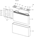
- FIG. 1 shows a perspective view of an example secondary battery 100 having a positive electrode terminal-and-membrane integrated cap plate.
- FIGS. 2A and 2B respectively, show an exploded perspective view of the example secondary battery 100 having a positive electrode terminal-and-membrane integrated cap plate 151, and a cross-sectional view taken along the line I-I' of FIG. 1 .
- the secondary battery 100 may include an electrode assembly 110, a first terminal 120, a second terminal 130, a case 140 and a cap assembly 150.
- the electrode assembly 110 may be formed by winding or laminating a stacked structure including a first electrode plate 111, a separator 113, and a second electrode plate 112, which are formed of thin plates or layers.
- the first electrode plate 111 may serve as a negative electrode and the second electrode plate 112 may serve as a positive electrode, and vice versa.
- the first electrode plate 111 may be formed by coating a first electrode active material 111b including graphite or carbon on a first electrode current collector 111a formed as a metal foil made of copper, a copper alloy, nickel, or a nickel alloy, and include a first electrode uncoated portion that is a region without the first electrode active material 111b coated thereon.
- the first electrode plate 111 may include a first multi-tab 111c upwardly extending a set or predetermined length from the first electrode uncoated portion.
- the first multi-tab 111c becomes a passageway of the flow of current between the first electrode plate 111 and the outside of the first electrode plate 111.
- the present invention does not limit the material of the first electrode plate 111 to those listed herein.
- the multi-tab used herein may encompass the concept of multiple tabs, but aspects of the present invention are not limited thereto.
- the multi-tab used herein may also encompass the concept of a single tab.
- the second electrode plate 112 may be formed by coating a second electrode active material 112b including a transition metal oxide on a second electrode current collector 112a formed as a metal foil made of aluminum or an aluminum alloy, and may include a second electrode uncoated portion that is a region without the second electrode active material 112b coated thereon.
- the second electrode plate 112 may include a second multi-tab 112c upwardly extending a set or predetermined length from the second electrode uncoated portion.
- the second multi-tab 112c may be a passageway of the flow of current between the second electrode plate 112 and the outside of the second electrode plate 112 (e.g., the second current collector plate 131).
- the first and second multi-tabs 111c and 112c maintain a substantially parallel state with respect to each other.
- the material of the second electrode plate 112 is not limited to those listed herein.
- Polarities of the first electrode plate 111 and the second electrode plate 112 may change, and the first electrode plate 111 and the second electrode plate 112 may then be suitably arranged.
- a winding axis of the electrode assembly 110 may be substantially parallel or substantially horizontal with respect to the terminal axes of the first terminal 120 and the second terminal 130.
- the winding axis and the terminal axes may refer to axes in upward and downward directions in FIGS. 2A and 2B .
- the separator 113 may be disposed between the first electrode plate 111 and the second electrode plate 112 to avoid short-circuiting and allow movement of lithium ions.
- the separator 113 may be formed of polyethylene, polypropylene, or a composite film including polyethylene and polypropylene. The material of the separator 113 is not limited to those listed herein.
- a first terminal 120 and a second terminal 130 are electrically connected to the first electrode plate 111 and the second electrode plate 112, and are positioned at left and right sides of an upper portion of the electrode assembly 110, respectively.
- the electrode assembly 110 is housed in the case 140 together with the electrolyte.
- the electrolyte may include an organic solvent, such as EC, PC, DEC, EMC, or DMC, and a lithium salt, such as LiPF6 or LiBF4.
- the electrolyte may be in a liquid, solid or gel phase.
- the first terminal 120 may be formed of a metal and may be electrically connected to the first electrode plate 111.
- the first terminal 120 may include a first current collector plate 121, a first terminal pillar 122 and a first terminal plate 123.
- the first terminal pillar 122 is electrically/mechanically connected between the first current collector plate 121 and the first terminal plate 123.
- the first current collector plate 121 contacts the first multi-tab 111c protruding from one side (e.g., the left) of the upper portion of the electrode assembly 110.
- the first current collector plate 121 is welded to the first multi-tab 111c.
- the first current collector plate 121 may include a hole formed at one side, and the first terminal pillar 122 is fitted into the hole for riveting or welding.
- the first current collector plate 121 may be formed of, for example, copper or a copper alloy. However, the material of the first current collector plate 121 is not limited to those listed herein.
- the first terminal pillar 122 upwardly protrudes and extends a set or predetermined length from the cap plate 151 while passing through the cap plate 151, which will later be described.
- the terminal pillar 122 may be electrically connected to the first current collector plate 121 at a lower portion of the cap plate 151.
- the first terminal pillar 122 is electrically insulated from the cap plate 151.
- the first terminal pillar 122 may pass through the cap plate 151 and may be formed of, for example, copper, a copper alloy, nickel, a nickel alloy, aluminum or an aluminum alloy.
- the first terminal plate 123 may have at least one hole, and the first terminal pillar 122 may be coupled and welded to the hole.
- the first terminal plate 123 may be formed of, for example, aluminum or an aluminum alloy.
- laser beam may be provided to boundary regions of the first terminal pillar 122 and the first terminal plate 123, which are upwardly exposed, so that the boundary regions are melted and then cooled to be welded to each other. Regions resulting after the welding are denoted by reference numeral 124.
- the first terminal plate 123 may be formed of aluminum or an aluminum alloy, busbars formed of aluminum or an aluminum alloy may be easily welded.
- the second terminal 130 may also be formed of a metal and may be electrically connected to the second electrode plate 112.
- the second terminal 130 may be integrated into the cap plate 151, and may be formed of the same material as the cap plate 151.
- the second terminal 130 may include a second current collector plate 131, a support region 132, a terminal region 133, and a membrane 134.
- the support region 132, the terminal region 133, and the membrane 134 may be formed by a forging process at the time of forming the cap plate 151.
- the second current collector plate 131 may contact the second multi-tab 112c protruding from one side (e.g., the right) of the upper portion of the electrode assembly 110.
- the second current collector plate 131 may be welded to the second multi-tab 112c.
- the second current collector plate 131 may include a hole formed thereat, and the membrane 134 concavely located downwardly at the terminal region 133, may be connected to the hole.
- a protrusion may be at a lower end of the membrane 134, and may be coupled to the hole of the second current collector plate 131.
- the protrusion may be coupled to the second current collector plate 131, followed by riveting or welding.
- the second current collector plate 131 may be formed of, for example, aluminum or an aluminum alloy. However, the material of the second current collector plate 131 is not limited to those listed herein.
- the support region 132 may upwardly extend a set or predetermined length from the cap plate 151, and the terminal region 133 may be at a top end of the support region 132.
- the terminal region 133 may have the same height or thickness as the first terminal plate 123, and may have an outer shape similar to that of the first terminal plate 123.
- the terminal region 133 may be also formed of aluminum or an aluminum alloy, busbars made of aluminum or an aluminum alloy may be easily welded.
- the terminal region 133 may be integrated into the cap plate 151, the cap plate 151 and the case 140, which will later be described, may have the same polarity as the second terminal 130 (e.g., a positive polarity). Accordingly, the second terminal 130 may serve as a positive electrode terminal.
- the case 140 may be made of a conductive metal, such as aluminum, an aluminum alloy or nickel plated steel, and may have an approximately hexahedron shape provided with an opening through which the electrode assembly 110 is inserted and placed. Since the case 140 and the cap assembly 150 are illustrated in an assembled state in FIG. 2 , the opening of the case 140 is not shown. However, it will be appreciated that the opening corresponds to a substantially open portion of the edge of the cap assembly 150.
- the inner surface of the case 140 may be treated to be insulated from the electrode assembly 110, the first terminal 120, the second terminal 130, and the cap assembly 150.
- the cap assembly 150 may be coupled to the case 140.
- the cap assembly 150 may include the cap plate 151, a seal gasket 152, a plug 153, a safety vent 154, an upper insulation member 155, and a lower insulation member 156.
- the cap plate 151 closes the opening of the case 140 and may be made of the same material as the case 140.
- the cap plate 151 may be coupled to the case 140 by laser welding.
- the cap plate 151 since the cap plate 151 may have the same polarity with the second terminal 130, the cap plate 151 and the case 140 may also have the same polarity. Also, since the second terminal 130 and the membrane 134 are integrated into the cap plate 151, they may be considered as one single element of the cap plate 151.
- the seal gasket 152 may be made of an insulating material, and may be located between the first terminal pillar 122 and the cap plate 151.
- the seal gasket 152 may prevent or protect from the introduction of external moisture into the secondary battery 100 or the leakage of the electrolyte from the secondary battery 100.
- the plug 153 may close an electrolyte injection hole 151a of the cap plate 151.
- the safety vent 154 may be installed in a vent hole of the cap plate 151 and may have a notch 154a to be opened at a set pressure.
- the upper insulation member 155 may be located between the first terminal pillar 122 and the cap plate 151, and between the first terminal plate 123 and the cap plate 151. Moreover, the upper insulation member 155 may make close contact with the seal gasket 152. The upper insulation member 155 may insulates the first terminal pillar 122 and the first terminal plate 123 from the cap plate 151.
- the lower insulation member 156 may be between the first current collector plate 121 and the cap plate 151, thereby preventing or protecting from unnecessary short-circuits. In some examples, the lower insulation member 156 prevents or protects from a short-circuit between the first current collector plate 121 and the cap plate 151.
- FIG. 3 shows an enlarged cross-sectional view illustrating essential parts of the example secondary battery having a positive electrode terminal-and-membrane integrated cap plate 151.
- the terminal portion refers to a second terminal or a positive electrode terminal.
- the cap plate 151 may include the terminal portion 130 integrated thereinto, and the membrane 134 integrated into the terminal portion 130.
- the membrane 134 may be electrically connected to the electrode assembly 110 through the current collector plate 131.
- the terminal portion 130 may include the support region 132 substantially upwardly extending a set or predetermined length from the cap plate 151, and the terminal region 133 substantially horizontally extending from the support region 132.
- the support region 132 may be bent and extended in a substantially perpendicular direction with respect to a lengthwise direction of the cap plate 151, and the terminal region 133 may be bent and extended in a substantially horizontal direction with respect to the lengthwise direction of the cap plate 151.
- the membrane 134 may be concavely located substantially downwardly from the terminal region 133.
- the membrane 134 may be configured such that it is downwardly recessed a set or predetermined depth from the center of the terminal region 133.
- a thickness of the membrane 134 may be smaller than that of the terminal region 133.
- the thickness of the membrane 134 may gradually decrease substantially toward the lower end of the membrane 134.
- the membrane 134 may be connected to the electrode assembly 110 through the current collector plate 131, and the lower insulation plate 156 may be interposed between the current collector plate 131 and the cap plate 151. Therefore, the current collector plate 131 may not be directly electrically connected to the cap plate 151 but may be indirectly electrically connected to the cap plate 151 through the membrane 134.
- a protrusion 135 may be at the bottommost end of the membrane 134.
- the protrusion 135 may be coupled to the hole of the current collector plate 131, by riveting and/or welding, thereby allowing the protrusion 135 to be electrically connected to the current collector plate 131.
- the membrane 134 may be electrically connected to the current collector plate 131 through the protrusion 135.
- a terminal cavity 138 having a set or predetermined volume may be defined by the terminal portion 130 (the support region 132 and the terminal region 133) and the membrane 134.
- at least one throughhole 156a may be in the lower insulation plate 156 corresponding to the terminal cavity 138, and at least one throughhole 131a may be in the current collector plate 131, so that the terminal cavity 138 and the internal space of the case 140 can be connected to each other. Therefore, when the internal pressure of the case 140 becomes higher than a preset reference pressure, it may be transmitted to the terminal cavity 138 to invert the membrane 134.
- a fuse 136 having a relatively small width may be between the membrane 134 and the protrusion 135 or between the membrane 134 and the current collector plate 131. Since the fuse 136 may be designed to have a smaller sectional area than the membrane 134 and/or the protrusion 135, the fuse 136 may be melted and removed when an overcurrent flows through the fuse 136.
- FIGS. 4A and 4B show schematic views illustrating states before and after operations in an overcharge mode in an example secondary battery.
- the secondary battery according to the present specification enters an overcharge mode, a large amount of gases are generated due to decomposition of an electrolyte or active materials and the internal pressure sharply increases by the generated gases.
- the membrane 134 when the gas pressure exceeds a preset reference pressure, the membrane 134 is inverted and is electrically disconnected from the current collector plate 131. In some examples, as the membrane 134, the fuse 136 and/or the protrusion 135 are separated from the current collector plate 131, a current path between the current collector plate 131 and the membrane 134 is cut off. Therefore, the charging current is no longer supplied to the secondary battery, thereby preventing or protecting the secondary battery from being overcharged.
- FIG. 4B illustrates that the membrane 134 is completely inverted, the present invention is not limited thereto. Rather, the membrane 134 may be slightly separated from the current collector plate 131 in an overcharge mode.
- FIGS. 5A and 5B show schematic views illustrating states before and after operations in an external short-circuit mode in an example secondary battery.
- a short-circuit current flows to the membrane 134 and the terminal portion 130, through the current collector plate 131.
- the over-current may flow in the secondary battery through the current collector plate 131, the membrane 134, and the terminal portion 130 as illustrated by the arrow in FIG. 5A .
- the short-circuit current i.e., the overcurrent
- the fuse 136 between the membrane 134 and the current collector plate 131 and/or between the membrane 134 and the protrusion 135 is melted and removed. Accordingly, the short-circuit current (the overcurrent) between the current collector plate 131 and the membrane 134 is cut off as illustrated by the arrow in FIG. 5b , thereby preventing or protecting the secondary battery from getting into a dangerous state.
- FIG. 6 shows a partial cross-sectional view of an example secondary battery having a positive electrode terminal-and-membrane integrated cap plate 151.
- the secondary battery according to the present invention may further include a resin portion 137 at the edge of the fuse 136.
- the resin portion 137 surrounds the edge of the fuse 136 but does not come into contact with a bottom surface of the membrane 134 and the current collector plate 131 or a top surface of the protrusion 135. Therefore, an inverting operation of the membrane 134 is not impeded by the resin portion 137.
- an arc that may occur during the operation of the fuse 136 may be suppressed by the resin portion 137, thereby preventing or reducing the risk of a fire or explosion from occurring at the secondary battery due to the arc.
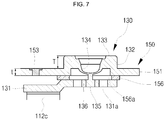
- FIG. 7 show a partial cross-sectional view of an example secondary battery having a positive electrode terminal-and-membrane integrated cap plate 151.
- a thickness of the terminal portion 130 may be greater than a thickness (t) of the cap plate 151.
- the thickness (T) of the terminal region 133 may be 1.5 to 3 times greater than the thickness (t) of the cap plate 151, but aspects of the present invention are not limited thereto.
- busbars may be welded to the terminal region 133 of the terminal portion 130 using laser beam.
- integrated welding regions are formed in the busbars and the terminal portion 130 by the laser beam. If depths of the welding regions are greater than the thickness of the terminal region 133, throughholes may be formed in the terminal region 133, and a welding failure may occur due to the throughholes.
- the thickness of the terminal region 133 of the positive electrode terminal may be greater than the thickness of the cap plate 151, and the depths of the welding regions formed in the terminal region 133 during laser welding may be smaller than the thickness of the terminal region 133. Therefore, the busbars can be welded to the terminal region 133 of the terminal portion 130 without a welding failure.
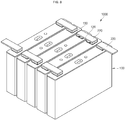
- FIG. 8 shows a perspective view illustrating an example battery module 1000 using the secondary battery.
- a plurality of secondary batteries 100 may be arranged in a line and a plurality of busbars 220 may be coupled to the plurality of secondary batteries 100, thereby completing a battery module 1000.
- a first terminal (e.g., a negative electrode terminal) of one of the plurality of secondary batteries 100 may be welded to a secondary terminal (e.g., a positive electrode terminal) 130 of another of the plurality of secondary batteries 100, which is adjacent to the one secondary battery 100 by the busbars 220, thereby providing the battery module 1000 having the plurality of secondary batteries 100 connected to one another in series.
- the busbars 220 may be made of aluminum or an aluminum alloy.
- the first terminal plate 124 of the first terminal 120 and the terminal region 133 of the second terminal 130 may also be made of aluminum or an aluminum alloy. Therefore, the busbars 220 can be welded to the first terminal 120 and the second terminal 130.
- the positive electrode terminal-and-membrane integrated cap plate according to the present specification may be made of aluminum or an aluminum alloy.
- the positive electrode terminal-and-membrane integrated cap plate according to the present specification may be formed using one selected from the group consisting of 1XXX series alloys (e.g., 1050, 1060, 1100, 1145, 1199, 1200, 1230, 1350, etc.), that is, pure aluminum of 99.0% or greater purity, 2XXX series alloys (e.g., 2011, 2014, 2017, 2018, 2124, 2219, 2319, 201.0, 203.0, 206.0, 224.0, 242.0, etc.), that is, Al-Cu alloys, 3XXX series alloys (e.g., 3003, 3004, 3102, 3105, 383.0, 385.0, A360, 390.0, etc.), that is, Al-Mn alloys, 4XXX series alloys (e.g., 4032, 4043, 4145, 4643, etc.), that is,
- the positive electrode terminal-and-membrane integrated cap plate according to the present specification can be made of pure aluminum, which is a 1XXX series alloy having excellent corrosion resistance, superb electrical and thermal conductivities, and good weldability and workability, or non-heat treatable alloys, which are 3XXX series alloys having various properties acquired by a cooling process with manganese as a principle alloying element, including a higher strength than pure aluminum, good weldability, corrosion resistance and workability.
- the terminal region and/or the membrane may be formed through various forging processes, as described above, the 1XXX series alloy or the 3XXX series alloys may be used.
- the positive electrode terminal-and-membrane integrated cap plate according to the present specification may be made of aluminum 1050 series alloys including, for example, aluminum: 99.5% min, copper: 0.05% max, iron: 0.4% max, magnesium: 0.05% max, manganese: 0.05% max, silicon: 0.25% max, titanium: 0.03% max, vanadium: 0.05% max, and zinc: 0.05% max, but are not limited thereto. Additionally, aluminum 1060, 1100, or 1199 series alloys may also be used.
- the positive electrode terminal-and-membrane integrated cap plate according to the present specification may be made of aluminum 3003 series alloys including, for example, aluminum: 96.8 to 99%, copper: 0.05 to 0.20%, iron: 0.70% max, manganese: 1.0 to 1.5%, silicon: 0.6% max, zinc: 0.1% max, and residuals: 0.15% max. Additionally, aluminum 3004 or 3102 series alloys may also be used.
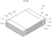
- FIGS. 9A and 9B respectively, show a cross-sectional view of an example secondary battery 200 having a positive electrode terminal-and-membrane integrated cap plate, and a perspective view illustrating an example electrode assembly 210.
- the secondary battery 200 having a positive electrode terminal-and-membrane integrated cap plate may include an electrode assembly 210, a first terminal 120, a second terminal 130, a case 140, and a cap assembly 150.
- the electrode assembly 210 may include, for example, a stack type electrode assembly or a winding type electrode assembly, but is not limited thereto.
- the stack type electrode assembly 210 may include a first electrode plate 211, a separator 213, and a second electrode plate 212, and may be provided by sequentially stacking these components in that order.
- the first electrode plate 211 may include a first electrode current collector 211a having a panel shape, a first electrode active material 211b coated on both surfaces or one surface of the first electrode current collector 211a, and a first electrode uncoated portion 211c at one side of the first electrode current collector 211a without the first electrode active material 211b coated thereon.
- the first electrode uncoated portion 211c of the first electrode plate 211 may be connected to a first bent portion 121a, bent approximately at right angle from a first current collector plate 121 of the first terminal 120.
- a lengthwise direction of the first bent portion 121a may be substantially parallel with a lengthwise direction of a first terminal pillar 122, and the first electrode uncoated portion 211c facing the first bent portion 121a may be welded to the first bent portion 121a through laser welding and/or ultrasonic welding.
- the second electrode plate 212 may include a second electrode current collector 212a having a panel shape, a second electrode active material 212b coated on both surfaces or one surface of the second electrode current collector 212a, and a second electrode uncoated portion 212c at one side of the second electrode current collector 212a without the second electrode active material 212b coated thereon.
- the second electrode uncoated portion 212c of the second electrode plate 212 may be connected to a second bent portion 131a bent approximately at right angle from a second current collector plate 131 of the second terminal 130.
- a lengthwise direction of the second bent portion 131a may be substantially parallel with a lengthwise direction of a fuse 136, and the second electrode uncoated portion 212c facing the second bent portion 131a may be welded to the second bent portion 131a through laser welding or ultrasonic welding.
- the current may be supplied from the electrode assembly 210 to the first terminal 120 and the second terminal 130 positioned on the electrode assembly 210 through the first bent portion 121a and the second bent portion 131a disposed at the left and right sides of the electrode assembly 210.
- the current may be supplied from the first terminal 120 and the second terminal 130 to the electrode assembly 210 through the first bent portion 121a and the second bent portion 131a, the first bent portion 121a and the second bent portion 131a being disposed at the left and right sides of a lower portion of the electrode assembly 210.
- regions excluding the first electrode uncoated portion 211c and the second electrode uncoated portion 212c in the electrode assembly 210 may be subjected to insulation treatment by being surrounded by a separator or a separate insulation member.
- a winding type electrode assemblies may also be used in the battery of the invention.
- a first electrode uncoated portion may be electrically connected to a first bent portion of a first current collector plate and a second electrode uncoated portion may be electrically connected to a second bent portion of a second current collector plate.
Landscapes
- Chemical & Material Sciences (AREA)
- Chemical Kinetics & Catalysis (AREA)
- Electrochemistry (AREA)
- General Chemical & Material Sciences (AREA)
- Engineering & Computer Science (AREA)
- Manufacturing & Machinery (AREA)
- Materials Engineering (AREA)
- Connection Of Batteries Or Terminals (AREA)
Abstract
Description
- The present invention relates to a secondary battery having a positive electrode terminal-and-membrane integrated cap plate.
- A secondary battery is a power storage system which can provide an excellent energy density for converting electrical energy into chemical energy and storing the same. Unlike primary batteries, which cannot be recharged, secondary batteries are rechargeable and are widely used in information technology (IT) devices, such as smart phones, cellular phones, notebook computers, tablet personal computers (tablet PCs), or the like. Recently, in order to reduce environmental pollution, electric vehicles have attracted high attention, and high-capacity secondary batteries are employed to power the electric vehicles. Accordingly, the development of secondary batteries having characteristics including high energy density, high power output, and stability, is desired.
- One or more of the drawbacks of the prior art could be avoided or at least reduced by means of the present invention. In particular, a secondary battery having a positive electrode terminal-and-membrane integrated cap plate is provided. Preferably, the present invention provides a secondary battery having a positive electrode terminal-and-membrane integrated cap plate, which can cut off a charging current in an overcharge mode by integrating a positive electrode terminal and a membrane into the cap plate, and can also cut off a short-circuit current in an external short-circuit mode by placing a fuse in a region of the membrane connected to the current collector plate.
- According to embodiments of the present invention, there is provided a secondary battery including a case having an opening, an electrode assembly housed in the opening of the case, and a cap plate configured for covering the opening of the case, wherein the cap plate may include a terminal portion integrated into the cap plate, and a membrane integrated into the terminal portion to be electrically connected to the electrode assembly.
- The terminal portion may include a support region extending vertically upwards from the cap plate, and a terminal region extending horizontally from the support region, wherein the membrane may be concavely located downwardly from the terminal region. A thickness of the membrane may be smaller than that of the terminal region. The membrane may be connected to the electrode assembly through a current collector plate. A lower insulation plate may be interposed between the cap plate and the current collector plate. A terminal cavity may be defined by the terminal portion and the membrane, and throughholes may be in the current collector plate and the lower insulation plate to cut off a charging current path when the membrane is inverted from the pressure of the gases being transmitted to the terminal cavity, the gases are generated when the secondary battery is overcharged. A fuse may be at a lower end of the membrane, and the fuse may be connected to the current collector plate. When the secondary battery is externally shorted-circuited, the fuse may be melted by a short-circuit current to cut off a short-circuit current path.
- As described above, various embodiments relate to a secondary battery having a positive electrode terminal-and-membrane integrated cap plate.
- Further embodiments of the present invention, relate to a secondary battery having a positive electrode terminal-and-membrane integrated cap plate, which can cut off a charging current in an overcharge mode by integrating a positive electrode terminal and a membrane into the cap plate. For example, when the secondary battery is overcharged, gases may be generated due to decomposition of active materials and an electrolyte, and the internal pressure of the secondary battery may rise. The membrane connected to the current collector plate may be inverted by the gas pressure, thereby cutting off the charging current.
- In addition, various embodiments relate to a secondary battery having a positive electrode terminal-and-membrane integrated cap plate, which can cut off a short-circuit current in an external short-circuit mode by placing a fuse in a region of the membrane connected to the current collector plate. For example, when the secondary battery is pierced by a conductor, crushed and/or externally short-circuited due to short-circuits occurring between the positive electrode terminal and the negative electrode terminal, the short-circuit current (overcurrent) may flow in the secondary battery. In such an event, a fuse connecting the membrane and the current collector plate is melted and removed, thereby cutting off the short-circuit current (overcurrent).
-
-
FIG. 1 shows a perspective view of an example secondary battery having a positive electrode terminal-and-membrane integrated cap plate; -
FIGS. 2A and2B respectively show an exploded perspective view of the secondary battery of -
FIG. 1 having a positive electrode terminal-and-membrane integrated cap plate, and a cross-sectional view taken along the line I-I' ofFIG. 1 ; -
FIG. 3 shows an enlarged cross-sectional view illustrating example parts of the example secondary battery having a positive electrode terminal-and-membrane integrated cap plate; -
FIGS. 4A and4B show schematic views illustrating states before and after operations in an overcharge mode in an example secondary battery; -
FIGS. 5A and5B show schematic views illustrating states before and after operations in an external short-circuit mode in an example secondary battery; -
FIG. 6 shows a partial cross-sectional view of an example secondary battery having a positive electrode terminal-and-membrane integrated cap plate; -
FIG. 7 shows a partial cross-sectional view of an example secondary battery having a positive electrode terminal-and-membrane integrated cap plate; -
FIG. 8 shows a perspective view illustrating an example battery module using the secondary battery; and -
FIGS. 9A and9B respectively show a cross-sectional view of an example secondary battery having a positive electrode terminal-and-membrane integrated cap plate, and a perspective view illustrating an example electrode assembly. - Hereinafter, an embodiment of the present invention will be described in detail.
- Various examples of the present invention may be embodied in many different forms and may not be construed as being limited to the example set forth herein. Rather, these examples of the disclosure are provided so that this disclosure will be thorough and complete and will convey inventive concepts of the disclosure to those skilled in the art.
- In addition, in the accompanying drawings, sizes or thicknesses of various components are exaggerated for brevity and clarity. Like numbers refer to like elements throughout. In addition, it will be understood that when an element A is referred to as being "connected to" an element B, the element A can be directly connected to the element B or an intervening element C may be present and the element A and the element B are indirectly connected to each other.
- The terminology used herein is for the purpose of describing particular example only and is not intended to be limiting of the disclosure. As used herein, the singular forms are intended to include the plural forms as well, unless the context clearly indicates otherwise. It will be further understood that the terms "comprise or include" and/or "comprising or including," when used in this specification, specify the presence of stated features, numbers, steps, operations, elements, and/or components, but do not preclude the presence or addition of one or more other features, numbers, steps, operations, elements, components, and/or groups thereof.
- It will be understood that, although the terms first, second, etc. may be used herein to describe various members, elements, regions, layers and/or sections, these members, elements, regions, layers and/or sections should not be limited by these terms. These terms are only used to distinguish one member, element, region, layer and/or section from another. Thus, for example, a first member, a first element, a first region, a first layer and/or a first section discussed below could be termed a second member, a second element, a second region, a second layer and/or a second section without departing from the teachings of the present invention.
- Spatially relative terms, such as "beneath," "below," "lower," "downward," "above," "upper," "upward," and the like, may be used herein for ease of description to describe one element or feature's relationship to another element(s) or feature(s) as illustrated in the figures. It will be understood that the spatially relative terms are intended to encompass different orientations of the device in use or operation in addition to the orientation depicted in the figures. For example, if the device in the figures is turned over, elements described as "below" or "beneath" other elements or features would then be oriented "above" the other elements or features. Thus, the exemplary term "below" can encompass both an orientation of above and below. Further, the use of "may" when describing embodiments of the inventive concept refers to "one or more embodiments of the inventive concept." Also, the term "exemplary" is intended to refer to an example or illustration.
- As used herein, the term "substantially," "about," and similar terms are used as terms of approximation and not as terms of degree, and are intended to account for the inherent deviations in measured or calculated values that would be recognized by those of ordinary skill in the art.
- Also, any numerical range recited herein is intended to include all sub-ranges of the same numerical precision subsumed within the recited range. For example, a range of "1.0 to 10.0" is intended to include all subranges between (and including) the recited minimum value of 1.0 and the recited maximum value of 10.0, that is, having a minimum value equal to or greater than 1.0 and a maximum value equal to or less than 10.0, such as, for example, 2.4 to 7.6. Any maximum numerical limitation recited herein is intended to include all lower numerical limitations subsumed therein and any minimum numerical limitation recited in this specification is intended to include all higher numerical limitations subsumed therein.
- In addition, the expression "positive electrode terminal-and-membrane integrated cap plate" described in the present specification refers to a cap plate in the shape of a rectangular flat panel with a positive electrode terminal and a membrane, which are integrated into the cap plate through multiple forging processes. In the drawings, thicknesses or widths of the positive electrode terminal, the membrane and the cap plate may be exaggerated for clarity, and illustration of some portions is omitted to avoid obscuring the subject matter of the present invention. In the present specification in some cases, the negative electrode terminal may also be referred to as a first terminal and the positive electrode terminal may also be referred to as a second terminal or terminal portion.
-
FIG. 1 shows a perspective view of an examplesecondary battery 100 having a positive electrode terminal-and-membrane integrated cap plate.FIGS. 2A and2B , respectively, show an exploded perspective view of the examplesecondary battery 100 having a positive electrode terminal-and-membrane integratedcap plate 151, and a cross-sectional view taken along the line I-I' ofFIG. 1 . - As illustrated in
FIGS. 1 ,2A , and2B , thesecondary battery 100 according to an example of the present invention may include anelectrode assembly 110, afirst terminal 120, asecond terminal 130, acase 140 and acap assembly 150. - The
electrode assembly 110 may be formed by winding or laminating a stacked structure including afirst electrode plate 111, aseparator 113, and asecond electrode plate 112, which are formed of thin plates or layers. Here, thefirst electrode plate 111 may serve as a negative electrode and thesecond electrode plate 112 may serve as a positive electrode, and vice versa. - The
first electrode plate 111 may be formed by coating a first electrodeactive material 111b including graphite or carbon on a first electrodecurrent collector 111a formed as a metal foil made of copper, a copper alloy, nickel, or a nickel alloy, and include a first electrode uncoated portion that is a region without the first electrodeactive material 111b coated thereon. In addition, thefirst electrode plate 111 may include a first multi-tab 111c upwardly extending a set or predetermined length from the first electrode uncoated portion. The first multi-tab 111c becomes a passageway of the flow of current between thefirst electrode plate 111 and the outside of thefirst electrode plate 111. Here, the present invention does not limit the material of thefirst electrode plate 111 to those listed herein. In addition, the multi-tab used herein may encompass the concept of multiple tabs, but aspects of the present invention are not limited thereto. The multi-tab used herein may also encompass the concept of a single tab. - The
second electrode plate 112 may be formed by coating a second electrodeactive material 112b including a transition metal oxide on a second electrodecurrent collector 112a formed as a metal foil made of aluminum or an aluminum alloy, and may include a second electrode uncoated portion that is a region without the second electrodeactive material 112b coated thereon. In addition, thesecond electrode plate 112 may include a second multi-tab 112c upwardly extending a set or predetermined length from the second electrode uncoated portion. The second multi-tab 112c may be a passageway of the flow of current between thesecond electrode plate 112 and the outside of the second electrode plate 112 (e.g., the second current collector plate 131). Here, the first and second multi-tabs 111c and 112c maintain a substantially parallel state with respect to each other. The material of thesecond electrode plate 112 is not limited to those listed herein. - Polarities of the
first electrode plate 111 and thesecond electrode plate 112 may change, and thefirst electrode plate 111 and thesecond electrode plate 112 may then be suitably arranged. - Here, a winding axis of the
electrode assembly 110 may be substantially parallel or substantially horizontal with respect to the terminal axes of thefirst terminal 120 and thesecond terminal 130. Here, the winding axis and the terminal axes may refer to axes in upward and downward directions inFIGS. 2A and2B . In addition, it means that when the winding axis and the terminal axes are referred to as being "substantially parallel or arranged substantially horizontal with respect to each other", they may not meet each other even by stretching them a suitably long distance or they may still eventually meet each other by stretching them along an extremely long distance. - The
separator 113 may be disposed between thefirst electrode plate 111 and thesecond electrode plate 112 to avoid short-circuiting and allow movement of lithium ions. Theseparator 113 may be formed of polyethylene, polypropylene, or a composite film including polyethylene and polypropylene. The material of theseparator 113 is not limited to those listed herein. - A
first terminal 120 and asecond terminal 130 are electrically connected to thefirst electrode plate 111 and thesecond electrode plate 112, and are positioned at left and right sides of an upper portion of theelectrode assembly 110, respectively. - The
electrode assembly 110 is housed in thecase 140 together with the electrolyte. The electrolyte may include an organic solvent, such as EC, PC, DEC, EMC, or DMC, and a lithium salt, such as LiPF6 or LiBF4. In addition, the electrolyte may be in a liquid, solid or gel phase. - The
first terminal 120 may be formed of a metal and may be electrically connected to thefirst electrode plate 111. Thefirst terminal 120 may include a firstcurrent collector plate 121, a firstterminal pillar 122 and a firstterminal plate 123. Here, the firstterminal pillar 122 is electrically/mechanically connected between the firstcurrent collector plate 121 and the firstterminal plate 123. - The first
current collector plate 121 contacts the first multi-tab 111c protruding from one side (e.g., the left) of the upper portion of theelectrode assembly 110. For example, the firstcurrent collector plate 121 is welded to the first multi-tab 111c. In addition, the firstcurrent collector plate 121 may include a hole formed at one side, and the firstterminal pillar 122 is fitted into the hole for riveting or welding. The firstcurrent collector plate 121 may be formed of, for example, copper or a copper alloy. However, the the material of the firstcurrent collector plate 121 is not limited to those listed herein. - The first
terminal pillar 122 upwardly protrudes and extends a set or predetermined length from thecap plate 151 while passing through thecap plate 151, which will later be described. Theterminal pillar 122 may be electrically connected to the firstcurrent collector plate 121 at a lower portion of thecap plate 151. Here, the firstterminal pillar 122 is electrically insulated from thecap plate 151. - The first
terminal pillar 122 may pass through thecap plate 151 and may be formed of, for example, copper, a copper alloy, nickel, a nickel alloy, aluminum or an aluminum alloy. - The first
terminal plate 123 may have at least one hole, and the firstterminal pillar 122 may be coupled and welded to the hole. Here, the firstterminal plate 123 may be formed of, for example, aluminum or an aluminum alloy. In some configurations, laser beam may be provided to boundary regions of the firstterminal pillar 122 and the firstterminal plate 123, which are upwardly exposed, so that the boundary regions are melted and then cooled to be welded to each other. Regions resulting after the welding are denoted byreference numeral 124. - As described above, since the first
terminal plate 123 may be formed of aluminum or an aluminum alloy, busbars formed of aluminum or an aluminum alloy may be easily welded. - The
second terminal 130 may also be formed of a metal and may be electrically connected to thesecond electrode plate 112. For example, thesecond terminal 130 may be integrated into thecap plate 151, and may be formed of the same material as thecap plate 151. Thesecond terminal 130 may include a secondcurrent collector plate 131, asupport region 132, aterminal region 133, and amembrane 134. Here, thesupport region 132, theterminal region 133, and themembrane 134, may be formed by a forging process at the time of forming thecap plate 151. - The second
current collector plate 131 may contact the second multi-tab 112c protruding from one side (e.g., the right) of the upper portion of theelectrode assembly 110. For example, the secondcurrent collector plate 131 may be welded to the second multi-tab 112c. The secondcurrent collector plate 131 may include a hole formed thereat, and themembrane 134 concavely located downwardly at theterminal region 133, may be connected to the hole. In some examples, a protrusion may be at a lower end of themembrane 134, and may be coupled to the hole of the secondcurrent collector plate 131. The protrusion may be coupled to the secondcurrent collector plate 131, followed by riveting or welding. The secondcurrent collector plate 131 may be formed of, for example, aluminum or an aluminum alloy. However, the material of the secondcurrent collector plate 131 is not limited to those listed herein. - The
support region 132 may upwardly extend a set or predetermined length from thecap plate 151, and theterminal region 133 may be at a top end of thesupport region 132. Theterminal region 133 may have the same height or thickness as the firstterminal plate 123, and may have an outer shape similar to that of the firstterminal plate 123. In addition, since theterminal region 133 may be also formed of aluminum or an aluminum alloy, busbars made of aluminum or an aluminum alloy may be easily welded. Here, since theterminal region 133 may be integrated into thecap plate 151, thecap plate 151 and thecase 140, which will later be described, may have the same polarity as the second terminal 130 (e.g., a positive polarity). Accordingly, thesecond terminal 130 may serve as a positive electrode terminal. - The
case 140 may be made of a conductive metal, such as aluminum, an aluminum alloy or nickel plated steel, and may have an approximately hexahedron shape provided with an opening through which theelectrode assembly 110 is inserted and placed. Since thecase 140 and thecap assembly 150 are illustrated in an assembled state inFIG. 2 , the opening of thecase 140 is not shown. However, it will be appreciated that the opening corresponds to a substantially open portion of the edge of thecap assembly 150. Here, the inner surface of thecase 140 may be treated to be insulated from theelectrode assembly 110, thefirst terminal 120, thesecond terminal 130, and thecap assembly 150. - The
cap assembly 150 may be coupled to thecase 140. In particular, thecap assembly 150 may include thecap plate 151, aseal gasket 152, aplug 153, asafety vent 154, anupper insulation member 155, and alower insulation member 156. - The
cap plate 151 closes the opening of thecase 140 and may be made of the same material as thecase 140. For example, thecap plate 151 may be coupled to thecase 140 by laser welding. As described above, since thecap plate 151 may have the same polarity with thesecond terminal 130, thecap plate 151 and thecase 140 may also have the same polarity. Also, since thesecond terminal 130 and themembrane 134 are integrated into thecap plate 151, they may be considered as one single element of thecap plate 151. - The
seal gasket 152 may be made of an insulating material, and may be located between the firstterminal pillar 122 and thecap plate 151. Theseal gasket 152 may prevent or protect from the introduction of external moisture into thesecondary battery 100 or the leakage of the electrolyte from thesecondary battery 100. - The
plug 153 may close anelectrolyte injection hole 151a of thecap plate 151. Thesafety vent 154 may be installed in a vent hole of thecap plate 151 and may have anotch 154a to be opened at a set pressure. - The
upper insulation member 155 may be located between the firstterminal pillar 122 and thecap plate 151, and between the firstterminal plate 123 and thecap plate 151. Moreover, theupper insulation member 155 may make close contact with theseal gasket 152. Theupper insulation member 155 may insulates the firstterminal pillar 122 and the firstterminal plate 123 from thecap plate 151. - The
lower insulation member 156 may be between the firstcurrent collector plate 121 and thecap plate 151, thereby preventing or protecting from unnecessary short-circuits. In some examples, thelower insulation member 156 prevents or protects from a short-circuit between the firstcurrent collector plate 121 and thecap plate 151. -
FIG. 3 shows an enlarged cross-sectional view illustrating essential parts of the example secondary battery having a positive electrode terminal-and-membrane integratedcap plate 151. In the following description, the terminal portion refers to a second terminal or a positive electrode terminal. - As illustrated in
FIG. 3 , thecap plate 151 may include theterminal portion 130 integrated thereinto, and themembrane 134 integrated into theterminal portion 130. Here, themembrane 134 may be electrically connected to theelectrode assembly 110 through thecurrent collector plate 131. - For example, the
terminal portion 130 may include thesupport region 132 substantially upwardly extending a set or predetermined length from thecap plate 151, and theterminal region 133 substantially horizontally extending from thesupport region 132. In some examples, thesupport region 132 may be bent and extended in a substantially perpendicular direction with respect to a lengthwise direction of thecap plate 151, and theterminal region 133 may be bent and extended in a substantially horizontal direction with respect to the lengthwise direction of thecap plate 151. - In addition, the
membrane 134 may be concavely located substantially downwardly from theterminal region 133. In some examples, themembrane 134 may be configured such that it is downwardly recessed a set or predetermined depth from the center of theterminal region 133. A thickness of themembrane 134 may be smaller than that of theterminal region 133. In addition, the thickness of themembrane 134 may gradually decrease substantially toward the lower end of themembrane 134. In addition, as described above, themembrane 134 may be connected to theelectrode assembly 110 through thecurrent collector plate 131, and thelower insulation plate 156 may be interposed between thecurrent collector plate 131 and thecap plate 151. Therefore, thecurrent collector plate 131 may not be directly electrically connected to thecap plate 151 but may be indirectly electrically connected to thecap plate 151 through themembrane 134. - Here, a
protrusion 135 may be at the bottommost end of themembrane 134. Theprotrusion 135 may be coupled to the hole of thecurrent collector plate 131, by riveting and/or welding, thereby allowing theprotrusion 135 to be electrically connected to thecurrent collector plate 131. In some examples, themembrane 134 may be electrically connected to thecurrent collector plate 131 through theprotrusion 135. - In addition, a
terminal cavity 138 having a set or predetermined volume may be defined by the terminal portion 130 (thesupport region 132 and the terminal region 133) and themembrane 134. Here, at least onethroughhole 156a may be in thelower insulation plate 156 corresponding to theterminal cavity 138, and at least onethroughhole 131a may be in thecurrent collector plate 131, so that theterminal cavity 138 and the internal space of thecase 140 can be connected to each other. Therefore, when the internal pressure of thecase 140 becomes higher than a preset reference pressure, it may be transmitted to theterminal cavity 138 to invert themembrane 134. - Alternatively, a
fuse 136 having a relatively small width may be between themembrane 134 and theprotrusion 135 or between themembrane 134 and thecurrent collector plate 131. Since thefuse 136 may be designed to have a smaller sectional area than themembrane 134 and/or theprotrusion 135, thefuse 136 may be melted and removed when an overcurrent flows through thefuse 136. -
FIGS. 4A and4B show schematic views illustrating states before and after operations in an overcharge mode in an example secondary battery. - If the secondary battery according to the present specification enters an overcharge mode, a large amount of gases are generated due to decomposition of an electrolyte or active materials and the internal pressure sharply increases by the generated gases.
- As illustrated in
FIGS. 4A and4B , if gases are generated in a case, the gases are transmitted to theterminal cavity 138 through the throughhole 131a of thecurrent collector plate 131 and the throughhole 156a of thelower insulation plate 156 as illustrated by the arrows inFIGS. 4A and4B . - Here, when the gas pressure exceeds a preset reference pressure, the
membrane 134 is inverted and is electrically disconnected from thecurrent collector plate 131. In some examples, as themembrane 134, thefuse 136 and/or theprotrusion 135 are separated from thecurrent collector plate 131, a current path between thecurrent collector plate 131 and themembrane 134 is cut off. Therefore, the charging current is no longer supplied to the secondary battery, thereby preventing or protecting the secondary battery from being overcharged. - Although,
FIG. 4B illustrates that themembrane 134 is completely inverted, the present invention is not limited thereto. Rather, themembrane 134 may be slightly separated from thecurrent collector plate 131 in an overcharge mode. -
FIGS. 5A and5B show schematic views illustrating states before and after operations in an external short-circuit mode in an example secondary battery. - If the secondary battery according to the present specification enters an external short-circuit mode, a short-circuit current flows to the
membrane 134 and theterminal portion 130, through thecurrent collector plate 131. In some examples, when the secondary battery is pierced by a conductor or crushed by a heavy material, or external positive and negative electrode terminals are directly short-circuited, the over-current may flow in the secondary battery through thecurrent collector plate 131, themembrane 134, and theterminal portion 130 as illustrated by the arrow inFIG. 5A . - As illustrated in
FIGS. 5A and5B , when the short-circuit current (i.e., the overcurrent) is in a higher level than the reference current, thefuse 136 between themembrane 134 and thecurrent collector plate 131 and/or between themembrane 134 and theprotrusion 135, is melted and removed. Accordingly, the short-circuit current (the overcurrent) between thecurrent collector plate 131 and themembrane 134 is cut off as illustrated by the arrow inFIG. 5b , thereby preventing or protecting the secondary battery from getting into a dangerous state. -
FIG. 6 shows a partial cross-sectional view of an example secondary battery having a positive electrode terminal-and-membrane integratedcap plate 151. - As illustrated in
FIG. 6 , the secondary battery according to the present invention may further include aresin portion 137 at the edge of thefuse 136. Theresin portion 137 surrounds the edge of thefuse 136 but does not come into contact with a bottom surface of themembrane 134 and thecurrent collector plate 131 or a top surface of theprotrusion 135. Therefore, an inverting operation of themembrane 134 is not impeded by theresin portion 137. - However, an arc that may occur during the operation of the
fuse 136 may be suppressed by theresin portion 137, thereby preventing or reducing the risk of a fire or explosion from occurring at the secondary battery due to the arc. -
FIG. 7 show a partial cross-sectional view of an example secondary battery having a positive electrode terminal-and-membrane integratedcap plate 151. - As illustrated in
FIG. 7 , in the secondary battery according to the present invention, a thickness of theterminal portion 130, specifically a thickness (T) of theterminal region 133 may be greater than a thickness (t) of thecap plate 151. For example, the thickness (T) of theterminal region 133 may be 1.5 to 3 times greater than the thickness (t) of thecap plate 151, but aspects of the present invention are not limited thereto. - In some configurations, busbars may be welded to the
terminal region 133 of theterminal portion 130 using laser beam. Here, integrated welding regions are formed in the busbars and theterminal portion 130 by the laser beam. If depths of the welding regions are greater than the thickness of theterminal region 133, throughholes may be formed in theterminal region 133, and a welding failure may occur due to the throughholes. In embodiments of the present invention, however, the thickness of theterminal region 133 of the positive electrode terminal may be greater than the thickness of thecap plate 151, and the depths of the welding regions formed in theterminal region 133 during laser welding may be smaller than the thickness of theterminal region 133. Therefore, the busbars can be welded to theterminal region 133 of theterminal portion 130 without a welding failure. -
FIG. 8 shows a perspective view illustrating anexample battery module 1000 using the secondary battery. - As illustrated in
FIG. 8 , a plurality ofsecondary batteries 100 may be arranged in a line and a plurality ofbusbars 220 may be coupled to the plurality ofsecondary batteries 100, thereby completing abattery module 1000. For example, a first terminal (e.g., a negative electrode terminal) of one of the plurality ofsecondary batteries 100 may be welded to a secondary terminal (e.g., a positive electrode terminal) 130 of another of the plurality ofsecondary batteries 100, which is adjacent to the onesecondary battery 100 by thebusbars 220, thereby providing thebattery module 1000 having the plurality ofsecondary batteries 100 connected to one another in series. Here, thebusbars 220 may be made of aluminum or an aluminum alloy. The firstterminal plate 124 of thefirst terminal 120 and theterminal region 133 of thesecond terminal 130 may also be made of aluminum or an aluminum alloy. Therefore, thebusbars 220 can be welded to thefirst terminal 120 and thesecond terminal 130. - Here, the positive electrode terminal-and-membrane integrated cap plate according to the present specification may be made of aluminum or an aluminum alloy. In some examples, the positive electrode terminal-and-membrane integrated cap plate according to the present specification may be formed using one selected from the group consisting of 1XXX series alloys (e.g., 1050, 1060, 1100, 1145, 1199, 1200, 1230, 1350, etc.), that is, pure aluminum of 99.0% or greater purity, 2XXX series alloys (e.g., 2011, 2014, 2017, 2018, 2124, 2219, 2319, 201.0, 203.0, 206.0, 224.0, 242.0, etc.), that is, Al-Cu alloys, 3XXX series alloys (e.g., 3003, 3004, 3102, 3105, 383.0, 385.0, A360, 390.0, etc.), that is, Al-Mn alloys, 4XXX series alloys (e.g., 4032, 4043, 4145, 4643, etc.), that is, Al-Si alloys, 5XXX series alloys (e.g., 5005, 5052, 5083, 5086, etc.), that is, Al-Mg alloys, 6XXX series alloys (e.g., 6061, 6063, etc.), that is, Al-Mg-Si alloys, 7XXX series alloys (e.g., 7075, 7050, 7049, 710.0, 711.0, etc.), that is, AI-Zn-(Mg,Cu) alloys, and 8XXX series alloys (e.g., 8006, 8111, 8079, 850.0, 851.0, 852.0), that is, AI+Other Elements (e.g., iron, nickel, lithium, etc.), except for the elements used in 7XXX or 2XXX series alloys.
- In some examples, the positive electrode terminal-and-membrane integrated cap plate according to the present specification can be made of pure aluminum, which is a 1XXX series alloy having excellent corrosion resistance, superb electrical and thermal conductivities, and good weldability and workability, or non-heat treatable alloys, which are 3XXX series alloys having various properties acquired by a cooling process with manganese as a principle alloying element, including a higher strength than pure aluminum, good weldability, corrosion resistance and workability.
- In the positive electrode terminal-and-membrane integrated cap plate according to the present specification, since the terminal region and/or the membrane may be formed through various forging processes, as described above, the 1XXX series alloy or the 3XXX series alloys may be used.
- The positive electrode terminal-and-membrane integrated cap plate according to the present specification may be made of aluminum 1050 series alloys including, for example, aluminum: 99.5% min, copper: 0.05% max, iron: 0.4% max, magnesium: 0.05% max, manganese: 0.05% max, silicon: 0.25% max, titanium: 0.03% max, vanadium: 0.05% max, and zinc: 0.05% max, but are not limited thereto. Additionally, aluminum 1060, 1100, or 1199 series alloys may also be used.
- In addition, the positive electrode terminal-and-membrane integrated cap plate according to the present specification may be made of aluminum 3003 series alloys including, for example, aluminum: 96.8 to 99%, copper: 0.05 to 0.20%, iron: 0.70% max, manganese: 1.0 to 1.5%, silicon: 0.6% max, zinc: 0.1% max, and residuals: 0.15% max. Additionally, aluminum 3004 or 3102 series alloys may also be used.
-
FIGS. 9A and9B , respectively, show a cross-sectional view of an examplesecondary battery 200 having a positive electrode terminal-and-membrane integrated cap plate, and a perspective view illustrating anexample electrode assembly 210. - As illustrated in
FIGS. 9A and9B , thesecondary battery 200 having a positive electrode terminal-and-membrane integrated cap plate according to the present invention may include anelectrode assembly 210, afirst terminal 120, asecond terminal 130, acase 140, and acap assembly 150. - The
electrode assembly 210 may include, for example, a stack type electrode assembly or a winding type electrode assembly, but is not limited thereto. The stacktype electrode assembly 210 may include afirst electrode plate 211, aseparator 213, and asecond electrode plate 212, and may be provided by sequentially stacking these components in that order. - The
first electrode plate 211 may include a first electrodecurrent collector 211a having a panel shape, a first electrodeactive material 211b coated on both surfaces or one surface of the first electrodecurrent collector 211a, and a first electrodeuncoated portion 211c at one side of the first electrodecurrent collector 211a without the first electrodeactive material 211b coated thereon. - The first electrode
uncoated portion 211c of thefirst electrode plate 211 may be connected to a firstbent portion 121a, bent approximately at right angle from a firstcurrent collector plate 121 of thefirst terminal 120. In an example, a lengthwise direction of the firstbent portion 121a may be substantially parallel with a lengthwise direction of a firstterminal pillar 122, and the first electrodeuncoated portion 211c facing the firstbent portion 121a may be welded to the firstbent portion 121a through laser welding and/or ultrasonic welding. - The
second electrode plate 212 may include a second electrodecurrent collector 212a having a panel shape, a second electrodeactive material 212b coated on both surfaces or one surface of the second electrodecurrent collector 212a, and a second electrodeuncoated portion 212c at one side of the second electrodecurrent collector 212a without the second electrodeactive material 212b coated thereon. - The second electrode
uncoated portion 212c of thesecond electrode plate 212 may be connected to a secondbent portion 131a bent approximately at right angle from a secondcurrent collector plate 131 of thesecond terminal 130. In an example embodiment, a lengthwise direction of the secondbent portion 131a may be substantially parallel with a lengthwise direction of afuse 136, and the second electrodeuncoated portion 212c facing the secondbent portion 131a may be welded to the secondbent portion 131a through laser welding or ultrasonic welding. - In this way, the current may be supplied from the
electrode assembly 210 to thefirst terminal 120 and thesecond terminal 130 positioned on theelectrode assembly 210 through the firstbent portion 121a and the secondbent portion 131a disposed at the left and right sides of theelectrode assembly 210. Conversely, the current may be supplied from thefirst terminal 120 and thesecond terminal 130 to theelectrode assembly 210 through the firstbent portion 121a and the secondbent portion 131a, the firstbent portion 121a and the secondbent portion 131a being disposed at the left and right sides of a lower portion of theelectrode assembly 210. - In some configurations, regions excluding the first electrode
uncoated portion 211c and the second electrodeuncoated portion 212c in theelectrode assembly 210 may be subjected to insulation treatment by being surrounded by a separator or a separate insulation member. In addition, although only the stack type electrode assembly is illustrated inFIGS. 9A and9B , a winding type electrode assemblies may also be used in the battery of the invention. In the winding type electrode assembly, like in the stack type electrode assembly, a first electrode uncoated portion may be electrically connected to a first bent portion of a first current collector plate and a second electrode uncoated portion may be electrically connected to a second bent portion of a second current collector plate. - While the secondary battery having a positive electrode terminal-and-membrane integrated cap plate of the present invention has been particularly shown and described with reference to example thereof, it will be understood by those of ordinary skill in the art that various changes in form and details may be made therein without departing from the scope of the present invention as defined by the following claims, and equivalents thereof.
Claims (12)
- A secondary battery (100) comprising:a case (140) having an opening;an electrode assembly (110) housed in the opening of the case; anda cap plate (151) configured for covering the opening of the case,wherein the cap plate comprises a terminal portion (130) integrated into the cap plate, wherein a membrane (134) integrated into the terminal portion is electrically connected to the electrode assembly.
- The secondary battery (100) of claim 1, wherein the terminal portion comprises a support region (132) upwardly extending from the cap plate and a terminal region (133) horizontally extending from the support region, wherein the membrane is concavely located downwardly from the terminal region.
- The secondary battery (100) of claim 2, wherein a thickness of the membrane is less than a thickness (T) of the terminal region.
- The secondary battery (100) of claim 2 or 3, wherein the thickness (T) of the terminal region is greater than a thickness (t) of the cap plate.
- The secondary battery (100) of any of claims 2 to 4, wherein the thickness (T) of the terminal region is about 1.5 to about 3 times greater than the thickness (t) of the cap plate.
- The secondary battery (100) of any of the preceding claims, wherein the membrane is connected to the electrode assembly through a current collector plate (131).
- The secondary battery (100) of claim 6, wherein a lower insulation plate (156) is interposed between the cap plate and the current collector plate.
- The secondary battery (100) of claim 7, wherein a terminal cavity (138) is defined by the terminal portion and the membrane, wherein one or more throughholes (131a, 156a) in the current collector plate and the lower insulation plate are configured to connect an internal space of the case (140) with the terminal cavity.
- The secondary battery (100) of any of the claims 6 to 8, wherein a fuse (136) is at a lower end of the membrane, the fuse being connected to the current collector plate.
- The secondary battery (100) of claim 9, wherein, the fuse is configured to be melted by a short-circuit current to cut off a short-circuit current path in response to the secondary battery being externally shorted-circuited.
- The secondary battery (100) of claim 9 or 10, further comprising a resin portion (137) surrounding the fuse and configured to suppress an arc during an operation of the fuse.
- The secondary battery (100) of any of claims 6 to 11, wherein the membrane comprises a protrusion (135) at a bottom end of the membrane, the membrane being electrically connected to the current collector plate through the protrusion.
Applications Claiming Priority (1)
| Application Number | Priority Date | Filing Date | Title |
|---|---|---|---|
| KR1020170073807A KR102454791B1 (en) | 2017-06-13 | 2017-06-13 | Secondary battery having positive electrode terminal and membrane-integrated cap plate |
Publications (3)
| Publication Number | Publication Date |
|---|---|
| EP3416213A2 true EP3416213A2 (en) | 2018-12-19 |
| EP3416213A3 EP3416213A3 (en) | 2019-01-02 |
| EP3416213B1 EP3416213B1 (en) | 2020-03-25 |
Family
ID=62567535
Family Applications (1)
| Application Number | Title | Priority Date | Filing Date |
|---|---|---|---|
| EP18176699.9A Active EP3416213B1 (en) | 2017-06-13 | 2018-06-08 | Secondary battery having positive electrode terminal-and-membrane integrated cap plate |
Country Status (4)
| Country | Link |
|---|---|
| US (1) | US11031621B2 (en) |
| EP (1) | EP3416213B1 (en) |
| KR (1) | KR102454791B1 (en) |
| CN (1) | CN109088040B (en) |
Cited By (3)
| Publication number | Priority date | Publication date | Assignee | Title |
|---|---|---|---|---|
| EP3731297A1 (en) * | 2019-04-26 | 2020-10-28 | Contemporary Amperex Technology Co., Limited | Battery module, secondary battery and cap assembly therefor |
| EP3799198A1 (en) * | 2019-09-30 | 2021-03-31 | Samsung SDI Co., Ltd. | Secondary battery |
| EP4037073A4 (en) * | 2019-09-26 | 2023-10-25 | SANYO Electric Co., Ltd. | Secondary battery |
Families Citing this family (5)
| Publication number | Priority date | Publication date | Assignee | Title |
|---|---|---|---|---|
| KR102663725B1 (en) | 2018-09-19 | 2024-05-07 | 삼성에스디아이 주식회사 | Secondary battery |
| KR102618121B1 (en) * | 2019-05-22 | 2023-12-27 | 삼성에스디아이 주식회사 | Secondary Battery |
| KR20220054130A (en) * | 2020-10-23 | 2022-05-02 | 삼성에스디아이 주식회사 | Secondary battery |
| CN215578674U (en) * | 2021-05-21 | 2022-01-18 | 湖北亿纬动力有限公司 | Assembling structure of positive pole and positive current collecting plate and battery |
| CN117855710A (en) * | 2024-03-07 | 2024-04-09 | 蜂巢能源科技股份有限公司 | Cover plate assembly, battery and battery pack |
Family Cites Families (16)
| Publication number | Priority date | Publication date | Assignee | Title |
|---|---|---|---|---|
| JP2605385Y2 (en) | 1993-08-04 | 2000-07-10 | 日本電池株式会社 | Square sealed battery |
| KR101254871B1 (en) | 2011-04-18 | 2013-04-15 | 로베르트 보쉬 게엠베하 | Secondary battery |
| JP2014096225A (en) * | 2012-11-07 | 2014-05-22 | Hitachi Vehicle Energy Ltd | Square secondary battery |
| CN202977584U (en) * | 2012-11-08 | 2013-06-05 | 宁德时代新能源科技有限公司 | Lithium ion battery over-charge safety protection device |
| KR101693291B1 (en) * | 2012-11-23 | 2017-01-05 | 삼성에스디아이 주식회사 | Rechargeable battery |
| DE102013204341A1 (en) * | 2013-03-13 | 2014-09-18 | Robert Bosch Gmbh | Security element for battery cell |
| KR101651988B1 (en) | 2013-09-30 | 2016-08-29 | 주식회사 엘지화학 | Cap assembly and secondary battery comprising the same |
| CN105637678B (en) * | 2013-10-16 | 2018-02-02 | 株式会社丰田自动织机 | Failure of current device and the electrical storage device for having used the failure of current device |
| KR102251330B1 (en) | 2014-11-19 | 2021-05-13 | 삼성에스디아이 주식회사 | Secondary Battery |
| KR101877601B1 (en) * | 2015-01-05 | 2018-08-09 | 주식회사 엘지화학 | A Cap Assembly of Novel Structure and Cylindrical Battery Comprising the Same |
| US10439195B2 (en) * | 2015-03-13 | 2019-10-08 | Kabushiki Kaisha Toyota Jidoshokki | Power storage device |
| JP6597014B2 (en) | 2015-07-21 | 2019-10-30 | 三洋電機株式会社 | Secondary battery |
| JP6281542B2 (en) | 2015-08-26 | 2018-02-21 | トヨタ自動車株式会社 | Manufacturing method of sealed battery |
| KR102453383B1 (en) * | 2015-10-19 | 2022-10-07 | 삼성에스디아이 주식회사 | Rechargeable battery module |
| CN105845850B (en) * | 2016-06-07 | 2019-01-08 | 宁德时代新能源科技股份有限公司 | Power battery top cover and power battery thereof |
| CN106450120B (en) | 2016-11-15 | 2019-02-22 | 宁德时代新能源科技股份有限公司 | Secondary battery and battery module |
-
2017
- 2017-06-13 KR KR1020170073807A patent/KR102454791B1/en active IP Right Grant
-
2018
- 2018-05-30 US US15/992,684 patent/US11031621B2/en active Active
- 2018-06-07 CN CN201810579411.9A patent/CN109088040B/en active Active
- 2018-06-08 EP EP18176699.9A patent/EP3416213B1/en active Active
Non-Patent Citations (1)
| Title |
|---|
| None |
Cited By (4)
| Publication number | Priority date | Publication date | Assignee | Title |
|---|---|---|---|---|
| EP3731297A1 (en) * | 2019-04-26 | 2020-10-28 | Contemporary Amperex Technology Co., Limited | Battery module, secondary battery and cap assembly therefor |
| US11258143B2 (en) * | 2019-04-26 | 2022-02-22 | Contemporary Amperex Technology Co., Limited | Battery module, secondary battery and cap assembly thereof |
| EP4037073A4 (en) * | 2019-09-26 | 2023-10-25 | SANYO Electric Co., Ltd. | Secondary battery |
| EP3799198A1 (en) * | 2019-09-30 | 2021-03-31 | Samsung SDI Co., Ltd. | Secondary battery |
Also Published As
| Publication number | Publication date |
|---|---|
| EP3416213B1 (en) | 2020-03-25 |
| KR102454791B1 (en) | 2022-10-14 |
| US20180358648A1 (en) | 2018-12-13 |
| CN109088040A (en) | 2018-12-25 |
| KR20180135594A (en) | 2018-12-21 |
| EP3416213A3 (en) | 2019-01-02 |
| US11031621B2 (en) | 2021-06-08 |
| CN109088040B (en) | 2021-07-30 |
Similar Documents
| Publication | Publication Date | Title |
|---|---|---|
| EP3416213B1 (en) | Secondary battery having positive electrode terminal-and-membrane integrated cap plate | |
| JP5383759B2 (en) | Secondary battery | |
| US11380954B2 (en) | Secondary battery having cathode terminal-integrated cap plate | |
| US9190636B2 (en) | Rechargeable battery | |
| US10050253B2 (en) | Rechargeable secondary battery having a fuse part on a cap plate | |
| US11289782B2 (en) | Secondary battery | |
| US10038172B2 (en) | Rechargeable battery | |
| US9570780B2 (en) | Rechargeable battery | |
| EP3544078B1 (en) | Secondary battery | |
| US11387528B2 (en) | Secondary battery | |
| US20150111072A1 (en) | Battery module | |
| US9768437B2 (en) | Rechargeable battery | |
| US10522813B2 (en) | Secondary battery | |
| US9741997B2 (en) | Rechargeable battery | |
| JP2015204284A (en) | Secondary battery | |
| EP2477257B1 (en) | Secondary battery | |
| US9583752B2 (en) | Secondary battery | |
| US9337468B2 (en) | Secondary battery | |
| US10930918B2 (en) | Secondary battery | |
| US10367185B2 (en) | Rechargeable battery | |
| US10333130B2 (en) | Secondary battery and secondary battery module | |
| US10115957B2 (en) | Secondary battery | |
| US20150349320A1 (en) | Secondary battery |
Legal Events
| Date | Code | Title | Description |
|---|---|---|---|
| PUAI | Public reference made under article 153(3) epc to a published international application that has entered the european phase |
Free format text: ORIGINAL CODE: 0009012 |
|
| STAA | Information on the status of an ep patent application or granted ep patent |
Free format text: STATUS: REQUEST FOR EXAMINATION WAS MADE |
|
| PUAL | Search report despatched |
Free format text: ORIGINAL CODE: 0009013 |
|
| 17P | Request for examination filed |
Effective date: 20180608 |
|
| AK | Designated contracting states |
Kind code of ref document: A2 Designated state(s): AL AT BE BG CH CY CZ DE DK EE ES FI FR GB GR HR HU IE IS IT LI LT LU LV MC MK MT NL NO PL PT RO RS SE SI SK SM TR |
|
| AX | Request for extension of the european patent |
Extension state: BA ME |
|
| AK | Designated contracting states |
Kind code of ref document: A3 Designated state(s): AL AT BE BG CH CY CZ DE DK EE ES FI FR GB GR HR HU IE IS IT LI LT LU LV MC MK MT NL NO PL PT RO RS SE SI SK SM TR |
|
| AX | Request for extension of the european patent |
Extension state: BA ME |
|
| RIC1 | Information provided on ipc code assigned before grant |
Ipc: H01M 2/34 20060101ALI20181126BHEP Ipc: H01M 2/30 20060101ALI20181126BHEP Ipc: H01M 2/26 20060101AFI20181126BHEP |
|
| REG | Reference to a national code |
Ref country code: DE Ref legal event code: R079 Ref document number: 602018003220 Country of ref document: DE Free format text: PREVIOUS MAIN CLASS: H01M0002260000 Ipc: H01M0002340000 |
|
| GRAP | Despatch of communication of intention to grant a patent |
Free format text: ORIGINAL CODE: EPIDOSNIGR1 |
|
| STAA | Information on the status of an ep patent application or granted ep patent |
Free format text: STATUS: GRANT OF PATENT IS INTENDED |
|
| INTG | Intention to grant announced |
Effective date: 20191120 |
|
| RIC1 | Information provided on ipc code assigned before grant |
Ipc: H01M 2/26 20060101ALI20191108BHEP Ipc: H01M 2/30 20060101ALI20191108BHEP Ipc: H01M 2/34 20060101AFI20191108BHEP |
|
| GRAS | Grant fee paid |
Free format text: ORIGINAL CODE: EPIDOSNIGR3 |
|
| GRAA | (expected) grant |
Free format text: ORIGINAL CODE: 0009210 |
|
| STAA | Information on the status of an ep patent application or granted ep patent |
Free format text: STATUS: THE PATENT HAS BEEN GRANTED |
|
| AK | Designated contracting states |
Kind code of ref document: B1 Designated state(s): AL AT BE BG CH CY CZ DE DK EE ES FI FR GB GR HR HU IE IS IT LI LT LU LV MC MK MT NL NO PL PT RO RS SE SI SK SM TR |
|
| REG | Reference to a national code |
Ref country code: GB Ref legal event code: FG4D |
|
| REG | Reference to a national code |
Ref country code: AT Ref legal event code: REF Ref document number: 1249620 Country of ref document: AT Kind code of ref document: T Effective date: 20200415 Ref country code: IE Ref legal event code: FG4D |
|
| REG | Reference to a national code |
Ref country code: DE Ref legal event code: R096 Ref document number: 602018003220 Country of ref document: DE |
|
| PG25 | Lapsed in a contracting state [announced via postgrant information from national office to epo] |
Ref country code: NO Free format text: LAPSE BECAUSE OF FAILURE TO SUBMIT A TRANSLATION OF THE DESCRIPTION OR TO PAY THE FEE WITHIN THE PRESCRIBED TIME-LIMIT Effective date: 20200625 Ref country code: FI Free format text: LAPSE BECAUSE OF FAILURE TO SUBMIT A TRANSLATION OF THE DESCRIPTION OR TO PAY THE FEE WITHIN THE PRESCRIBED TIME-LIMIT Effective date: 20200325 Ref country code: RS Free format text: LAPSE BECAUSE OF FAILURE TO SUBMIT A TRANSLATION OF THE DESCRIPTION OR TO PAY THE FEE WITHIN THE PRESCRIBED TIME-LIMIT Effective date: 20200325 |
|
| PG25 | Lapsed in a contracting state [announced via postgrant information from national office to epo] |
Ref country code: GR Free format text: LAPSE BECAUSE OF FAILURE TO SUBMIT A TRANSLATION OF THE DESCRIPTION OR TO PAY THE FEE WITHIN THE PRESCRIBED TIME-LIMIT Effective date: 20200626 Ref country code: HR Free format text: LAPSE BECAUSE OF FAILURE TO SUBMIT A TRANSLATION OF THE DESCRIPTION OR TO PAY THE FEE WITHIN THE PRESCRIBED TIME-LIMIT Effective date: 20200325 Ref country code: SE Free format text: LAPSE BECAUSE OF FAILURE TO SUBMIT A TRANSLATION OF THE DESCRIPTION OR TO PAY THE FEE WITHIN THE PRESCRIBED TIME-LIMIT Effective date: 20200325 Ref country code: LV Free format text: LAPSE BECAUSE OF FAILURE TO SUBMIT A TRANSLATION OF THE DESCRIPTION OR TO PAY THE FEE WITHIN THE PRESCRIBED TIME-LIMIT Effective date: 20200325 Ref country code: BG Free format text: LAPSE BECAUSE OF FAILURE TO SUBMIT A TRANSLATION OF THE DESCRIPTION OR TO PAY THE FEE WITHIN THE PRESCRIBED TIME-LIMIT Effective date: 20200625 |
|
| REG | Reference to a national code |
Ref country code: NL Ref legal event code: MP Effective date: 20200325 |
|
| REG | Reference to a national code |
Ref country code: LT Ref legal event code: MG4D |
|
| PG25 | Lapsed in a contracting state [announced via postgrant information from national office to epo] |
Ref country code: NL Free format text: LAPSE BECAUSE OF FAILURE TO SUBMIT A TRANSLATION OF THE DESCRIPTION OR TO PAY THE FEE WITHIN THE PRESCRIBED TIME-LIMIT Effective date: 20200325 |
|
| PG25 | Lapsed in a contracting state [announced via postgrant information from national office to epo] |
Ref country code: EE Free format text: LAPSE BECAUSE OF FAILURE TO SUBMIT A TRANSLATION OF THE DESCRIPTION OR TO PAY THE FEE WITHIN THE PRESCRIBED TIME-LIMIT Effective date: 20200325 Ref country code: LT Free format text: LAPSE BECAUSE OF FAILURE TO SUBMIT A TRANSLATION OF THE DESCRIPTION OR TO PAY THE FEE WITHIN THE PRESCRIBED TIME-LIMIT Effective date: 20200325 Ref country code: SM Free format text: LAPSE BECAUSE OF FAILURE TO SUBMIT A TRANSLATION OF THE DESCRIPTION OR TO PAY THE FEE WITHIN THE PRESCRIBED TIME-LIMIT Effective date: 20200325 Ref country code: PT Free format text: LAPSE BECAUSE OF FAILURE TO SUBMIT A TRANSLATION OF THE DESCRIPTION OR TO PAY THE FEE WITHIN THE PRESCRIBED TIME-LIMIT Effective date: 20200818 Ref country code: RO Free format text: LAPSE BECAUSE OF FAILURE TO SUBMIT A TRANSLATION OF THE DESCRIPTION OR TO PAY THE FEE WITHIN THE PRESCRIBED TIME-LIMIT Effective date: 20200325 Ref country code: CZ Free format text: LAPSE BECAUSE OF FAILURE TO SUBMIT A TRANSLATION OF THE DESCRIPTION OR TO PAY THE FEE WITHIN THE PRESCRIBED TIME-LIMIT Effective date: 20200325 Ref country code: IS Free format text: LAPSE BECAUSE OF FAILURE TO SUBMIT A TRANSLATION OF THE DESCRIPTION OR TO PAY THE FEE WITHIN THE PRESCRIBED TIME-LIMIT Effective date: 20200725 Ref country code: SK Free format text: LAPSE BECAUSE OF FAILURE TO SUBMIT A TRANSLATION OF THE DESCRIPTION OR TO PAY THE FEE WITHIN THE PRESCRIBED TIME-LIMIT Effective date: 20200325 |
|
| REG | Reference to a national code |
Ref country code: AT Ref legal event code: MK05 Ref document number: 1249620 Country of ref document: AT Kind code of ref document: T Effective date: 20200325 |
|
| REG | Reference to a national code |
Ref country code: DE Ref legal event code: R079 Ref document number: 602018003220 Country of ref document: DE Free format text: PREVIOUS MAIN CLASS: H01M0002340000 Ipc: H01M0050572000 |
|
| REG | Reference to a national code |
Ref country code: DE Ref legal event code: R097 Ref document number: 602018003220 Country of ref document: DE |
|
| PG25 | Lapsed in a contracting state [announced via postgrant information from national office to epo] |
Ref country code: IT Free format text: LAPSE BECAUSE OF FAILURE TO SUBMIT A TRANSLATION OF THE DESCRIPTION OR TO PAY THE FEE WITHIN THE PRESCRIBED TIME-LIMIT Effective date: 20200325 Ref country code: ES Free format text: LAPSE BECAUSE OF FAILURE TO SUBMIT A TRANSLATION OF THE DESCRIPTION OR TO PAY THE FEE WITHIN THE PRESCRIBED TIME-LIMIT Effective date: 20200325 Ref country code: DK Free format text: LAPSE BECAUSE OF FAILURE TO SUBMIT A TRANSLATION OF THE DESCRIPTION OR TO PAY THE FEE WITHIN THE PRESCRIBED TIME-LIMIT Effective date: 20200325 Ref country code: AT Free format text: LAPSE BECAUSE OF FAILURE TO SUBMIT A TRANSLATION OF THE DESCRIPTION OR TO PAY THE FEE WITHIN THE PRESCRIBED TIME-LIMIT Effective date: 20200325 Ref country code: MC Free format text: LAPSE BECAUSE OF FAILURE TO SUBMIT A TRANSLATION OF THE DESCRIPTION OR TO PAY THE FEE WITHIN THE PRESCRIBED TIME-LIMIT Effective date: 20200325 |
|
| PLBE | No opposition filed within time limit |
Free format text: ORIGINAL CODE: 0009261 |
|
| STAA | Information on the status of an ep patent application or granted ep patent |
Free format text: STATUS: NO OPPOSITION FILED WITHIN TIME LIMIT |
|
| PG25 | Lapsed in a contracting state [announced via postgrant information from national office to epo] |
Ref country code: PL Free format text: LAPSE BECAUSE OF FAILURE TO SUBMIT A TRANSLATION OF THE DESCRIPTION OR TO PAY THE FEE WITHIN THE PRESCRIBED TIME-LIMIT Effective date: 20200325 |
|
| 26N | No opposition filed |
Effective date: 20210112 |
|
| PG25 | Lapsed in a contracting state [announced via postgrant information from national office to epo] |
Ref country code: LU Free format text: LAPSE BECAUSE OF NON-PAYMENT OF DUE FEES Effective date: 20200608 |
|
| REG | Reference to a national code |
Ref country code: BE Ref legal event code: MM Effective date: 20200630 |
|
| PG25 | Lapsed in a contracting state [announced via postgrant information from national office to epo] |
Ref country code: IE Free format text: LAPSE BECAUSE OF NON-PAYMENT OF DUE FEES Effective date: 20200608 |
|
| PG25 | Lapsed in a contracting state [announced via postgrant information from national office to epo] |
Ref country code: SI Free format text: LAPSE BECAUSE OF FAILURE TO SUBMIT A TRANSLATION OF THE DESCRIPTION OR TO PAY THE FEE WITHIN THE PRESCRIBED TIME-LIMIT Effective date: 20200325 Ref country code: BE Free format text: LAPSE BECAUSE OF NON-PAYMENT OF DUE FEES Effective date: 20200630 |
|
| REG | Reference to a national code |
Ref country code: CH Ref legal event code: PL |
|
| PG25 | Lapsed in a contracting state [announced via postgrant information from national office to epo] |
Ref country code: LI Free format text: LAPSE BECAUSE OF NON-PAYMENT OF DUE FEES Effective date: 20210630 Ref country code: CH Free format text: LAPSE BECAUSE OF NON-PAYMENT OF DUE FEES Effective date: 20210630 |
|
| PG25 | Lapsed in a contracting state [announced via postgrant information from national office to epo] |
Ref country code: TR Free format text: LAPSE BECAUSE OF FAILURE TO SUBMIT A TRANSLATION OF THE DESCRIPTION OR TO PAY THE FEE WITHIN THE PRESCRIBED TIME-LIMIT Effective date: 20200325 Ref country code: MT Free format text: LAPSE BECAUSE OF FAILURE TO SUBMIT A TRANSLATION OF THE DESCRIPTION OR TO PAY THE FEE WITHIN THE PRESCRIBED TIME-LIMIT Effective date: 20200325 Ref country code: CY Free format text: LAPSE BECAUSE OF FAILURE TO SUBMIT A TRANSLATION OF THE DESCRIPTION OR TO PAY THE FEE WITHIN THE PRESCRIBED TIME-LIMIT Effective date: 20200325 |
|
| PG25 | Lapsed in a contracting state [announced via postgrant information from national office to epo] |
Ref country code: MK Free format text: LAPSE BECAUSE OF FAILURE TO SUBMIT A TRANSLATION OF THE DESCRIPTION OR TO PAY THE FEE WITHIN THE PRESCRIBED TIME-LIMIT Effective date: 20200325 Ref country code: AL Free format text: LAPSE BECAUSE OF FAILURE TO SUBMIT A TRANSLATION OF THE DESCRIPTION OR TO PAY THE FEE WITHIN THE PRESCRIBED TIME-LIMIT Effective date: 20200325 |
|
| P01 | Opt-out of the competence of the unified patent court (upc) registered |
Effective date: 20230528 |
|
| PGFP | Annual fee paid to national office [announced via postgrant information from national office to epo] |
Ref country code: GB Payment date: 20240530 Year of fee payment: 7 |
|
| PGFP | Annual fee paid to national office [announced via postgrant information from national office to epo] |
Ref country code: DE Payment date: 20240604 Year of fee payment: 7 |
|
| PGFP | Annual fee paid to national office [announced via postgrant information from national office to epo] |
Ref country code: FR Payment date: 20240611 Year of fee payment: 7 |