EP3416008A1 - Method for modeling additive manufacturing of a part - Google Patents
Method for modeling additive manufacturing of a part Download PDFInfo
- Publication number
- EP3416008A1 EP3416008A1 EP18176982.9A EP18176982A EP3416008A1 EP 3416008 A1 EP3416008 A1 EP 3416008A1 EP 18176982 A EP18176982 A EP 18176982A EP 3416008 A1 EP3416008 A1 EP 3416008A1
- Authority
- EP
- European Patent Office
- Prior art keywords
- equation
- output
- additive manufacturing
- process map
- model
- Prior art date
- Legal status (The legal status is an assumption and is not a legal conclusion. Google has not performed a legal analysis and makes no representation as to the accuracy of the status listed.)
- Withdrawn
Links
Images

Classifications
-
- G—PHYSICS
- G05—CONTROLLING; REGULATING
- G05B—CONTROL OR REGULATING SYSTEMS IN GENERAL; FUNCTIONAL ELEMENTS OF SUCH SYSTEMS; MONITORING OR TESTING ARRANGEMENTS FOR SUCH SYSTEMS OR ELEMENTS
- G05B17/00—Systems involving the use of models or simulators of said systems
- G05B17/02—Systems involving the use of models or simulators of said systems electric
-
- B—PERFORMING OPERATIONS; TRANSPORTING
- B22—CASTING; POWDER METALLURGY
- B22F—WORKING METALLIC POWDER; MANUFACTURE OF ARTICLES FROM METALLIC POWDER; MAKING METALLIC POWDER; APPARATUS OR DEVICES SPECIALLY ADAPTED FOR METALLIC POWDER
- B22F10/00—Additive manufacturing of workpieces or articles from metallic powder
- B22F10/30—Process control
- B22F10/31—Calibration of process steps or apparatus settings, e.g. before or during manufacturing
-
- B—PERFORMING OPERATIONS; TRANSPORTING
- B22—CASTING; POWDER METALLURGY
- B22F—WORKING METALLIC POWDER; MANUFACTURE OF ARTICLES FROM METALLIC POWDER; MAKING METALLIC POWDER; APPARATUS OR DEVICES SPECIALLY ADAPTED FOR METALLIC POWDER
- B22F10/00—Additive manufacturing of workpieces or articles from metallic powder
- B22F10/30—Process control
- B22F10/36—Process control of energy beam parameters
-
- B—PERFORMING OPERATIONS; TRANSPORTING
- B22—CASTING; POWDER METALLURGY
- B22F—WORKING METALLIC POWDER; MANUFACTURE OF ARTICLES FROM METALLIC POWDER; MAKING METALLIC POWDER; APPARATUS OR DEVICES SPECIALLY ADAPTED FOR METALLIC POWDER
- B22F10/00—Additive manufacturing of workpieces or articles from metallic powder
- B22F10/30—Process control
- B22F10/36—Process control of energy beam parameters
- B22F10/366—Scanning parameters, e.g. hatch distance or scanning strategy
-
- B—PERFORMING OPERATIONS; TRANSPORTING
- B22—CASTING; POWDER METALLURGY
- B22F—WORKING METALLIC POWDER; MANUFACTURE OF ARTICLES FROM METALLIC POWDER; MAKING METALLIC POWDER; APPARATUS OR DEVICES SPECIALLY ADAPTED FOR METALLIC POWDER
- B22F10/00—Additive manufacturing of workpieces or articles from metallic powder
- B22F10/30—Process control
- B22F10/38—Process control to achieve specific product aspects, e.g. surface smoothness, density, porosity or hollow structures
-
- B—PERFORMING OPERATIONS; TRANSPORTING
- B22—CASTING; POWDER METALLURGY
- B22F—WORKING METALLIC POWDER; MANUFACTURE OF ARTICLES FROM METALLIC POWDER; MAKING METALLIC POWDER; APPARATUS OR DEVICES SPECIALLY ADAPTED FOR METALLIC POWDER
- B22F10/00—Additive manufacturing of workpieces or articles from metallic powder
- B22F10/80—Data acquisition or data processing
- B22F10/85—Data acquisition or data processing for controlling or regulating additive manufacturing processes
-
- B—PERFORMING OPERATIONS; TRANSPORTING
- B33—ADDITIVE MANUFACTURING TECHNOLOGY
- B33Y—ADDITIVE MANUFACTURING, i.e. MANUFACTURING OF THREE-DIMENSIONAL [3D] OBJECTS BY ADDITIVE DEPOSITION, ADDITIVE AGGLOMERATION OR ADDITIVE LAYERING, e.g. BY 3D PRINTING, STEREOLITHOGRAPHY OR SELECTIVE LASER SINTERING
- B33Y50/00—Data acquisition or data processing for additive manufacturing
- B33Y50/02—Data acquisition or data processing for additive manufacturing for controlling or regulating additive manufacturing processes
-
- G—PHYSICS
- G05—CONTROLLING; REGULATING
- G05B—CONTROL OR REGULATING SYSTEMS IN GENERAL; FUNCTIONAL ELEMENTS OF SUCH SYSTEMS; MONITORING OR TESTING ARRANGEMENTS FOR SUCH SYSTEMS OR ELEMENTS
- G05B13/00—Adaptive control systems, i.e. systems automatically adjusting themselves to have a performance which is optimum according to some preassigned criterion
- G05B13/02—Adaptive control systems, i.e. systems automatically adjusting themselves to have a performance which is optimum according to some preassigned criterion electric
- G05B13/04—Adaptive control systems, i.e. systems automatically adjusting themselves to have a performance which is optimum according to some preassigned criterion electric involving the use of models or simulators
- G05B13/041—Adaptive control systems, i.e. systems automatically adjusting themselves to have a performance which is optimum according to some preassigned criterion electric involving the use of models or simulators in which a variable is automatically adjusted to optimise the performance
-
- G—PHYSICS
- G05—CONTROLLING; REGULATING
- G05B—CONTROL OR REGULATING SYSTEMS IN GENERAL; FUNCTIONAL ELEMENTS OF SUCH SYSTEMS; MONITORING OR TESTING ARRANGEMENTS FOR SUCH SYSTEMS OR ELEMENTS
- G05B13/00—Adaptive control systems, i.e. systems automatically adjusting themselves to have a performance which is optimum according to some preassigned criterion
- G05B13/02—Adaptive control systems, i.e. systems automatically adjusting themselves to have a performance which is optimum according to some preassigned criterion electric
- G05B13/04—Adaptive control systems, i.e. systems automatically adjusting themselves to have a performance which is optimum according to some preassigned criterion electric involving the use of models or simulators
- G05B13/042—Adaptive control systems, i.e. systems automatically adjusting themselves to have a performance which is optimum according to some preassigned criterion electric involving the use of models or simulators in which a parameter or coefficient is automatically adjusted to optimise the performance
-
- G—PHYSICS
- G05—CONTROLLING; REGULATING
- G05B—CONTROL OR REGULATING SYSTEMS IN GENERAL; FUNCTIONAL ELEMENTS OF SUCH SYSTEMS; MONITORING OR TESTING ARRANGEMENTS FOR SUCH SYSTEMS OR ELEMENTS
- G05B19/00—Program-control systems
- G05B19/02—Program-control systems electric
- G05B19/18—Numerical control [NC], i.e. automatically operating machines, in particular machine tools, e.g. in a manufacturing environment, so as to execute positioning, movement or co-ordinated operations by means of program data in numerical form
- G05B19/4097—Numerical control [NC], i.e. automatically operating machines, in particular machine tools, e.g. in a manufacturing environment, so as to execute positioning, movement or co-ordinated operations by means of program data in numerical form characterised by using design data to control NC machines, e.g. CAD/CAM
- G05B19/4099—Surface or curve machining, making three-dimensional [3D] objects, e.g. desktop manufacturing
-
- B—PERFORMING OPERATIONS; TRANSPORTING
- B22—CASTING; POWDER METALLURGY
- B22F—WORKING METALLIC POWDER; MANUFACTURE OF ARTICLES FROM METALLIC POWDER; MAKING METALLIC POWDER; APPARATUS OR DEVICES SPECIALLY ADAPTED FOR METALLIC POWDER
- B22F10/00—Additive manufacturing of workpieces or articles from metallic powder
- B22F10/20—Direct sintering or melting
- B22F10/25—Direct deposition of metal particles, e.g. direct metal deposition [DMD] or laser engineered net shaping [LENS]
-
- B—PERFORMING OPERATIONS; TRANSPORTING
- B22—CASTING; POWDER METALLURGY
- B22F—WORKING METALLIC POWDER; MANUFACTURE OF ARTICLES FROM METALLIC POWDER; MAKING METALLIC POWDER; APPARATUS OR DEVICES SPECIALLY ADAPTED FOR METALLIC POWDER
- B22F10/00—Additive manufacturing of workpieces or articles from metallic powder
- B22F10/20—Direct sintering or melting
- B22F10/28—Powder bed fusion, e.g. selective laser melting [SLM] or electron beam melting [EBM]
-
- G—PHYSICS
- G05—CONTROLLING; REGULATING
- G05B—CONTROL OR REGULATING SYSTEMS IN GENERAL; FUNCTIONAL ELEMENTS OF SUCH SYSTEMS; MONITORING OR TESTING ARRANGEMENTS FOR SUCH SYSTEMS OR ELEMENTS
- G05B2219/00—Program-control systems
- G05B2219/30—Nc systems
- G05B2219/49—Nc machine tool, till multiple
- G05B2219/49013—Deposit layers, cured by scanning laser, stereo lithography SLA, prototyping
-
- G—PHYSICS
- G05—CONTROLLING; REGULATING
- G05B—CONTROL OR REGULATING SYSTEMS IN GENERAL; FUNCTIONAL ELEMENTS OF SUCH SYSTEMS; MONITORING OR TESTING ARRANGEMENTS FOR SUCH SYSTEMS OR ELEMENTS
- G05B2219/00—Program-control systems
- G05B2219/30—Nc systems
- G05B2219/49—Nc machine tool, till multiple
- G05B2219/49023—3-D printing, layer of powder, add drops of binder in layer, new powder
-
- G—PHYSICS
- G05—CONTROLLING; REGULATING
- G05B—CONTROL OR REGULATING SYSTEMS IN GENERAL; FUNCTIONAL ELEMENTS OF SUCH SYSTEMS; MONITORING OR TESTING ARRANGEMENTS FOR SUCH SYSTEMS OR ELEMENTS
- G05B2219/00—Program-control systems
- G05B2219/30—Nc systems
- G05B2219/49—Nc machine tool, till multiple
- G05B2219/49027—SALD selective area laser deposition, vapor solidifies on surface
-
- G—PHYSICS
- G05—CONTROLLING; REGULATING
- G05B—CONTROL OR REGULATING SYSTEMS IN GENERAL; FUNCTIONAL ELEMENTS OF SUCH SYSTEMS; MONITORING OR TESTING ARRANGEMENTS FOR SUCH SYSTEMS OR ELEMENTS
- G05B2219/00—Program-control systems
- G05B2219/30—Nc systems
- G05B2219/49—Nc machine tool, till multiple
- G05B2219/49029—Virtual rapid prototyping, create a virtual prototype, simulate rapid prototyping process
-
- Y—GENERAL TAGGING OF NEW TECHNOLOGICAL DEVELOPMENTS; GENERAL TAGGING OF CROSS-SECTIONAL TECHNOLOGIES SPANNING OVER SEVERAL SECTIONS OF THE IPC; TECHNICAL SUBJECTS COVERED BY FORMER USPC CROSS-REFERENCE ART COLLECTIONS [XRACs] AND DIGESTS
- Y02—TECHNOLOGIES OR APPLICATIONS FOR MITIGATION OR ADAPTATION AGAINST CLIMATE CHANGE
- Y02P—CLIMATE CHANGE MITIGATION TECHNOLOGIES IN THE PRODUCTION OR PROCESSING OF GOODS
- Y02P10/00—Technologies related to metal processing
- Y02P10/25—Process efficiency
-
- Y—GENERAL TAGGING OF NEW TECHNOLOGICAL DEVELOPMENTS; GENERAL TAGGING OF CROSS-SECTIONAL TECHNOLOGIES SPANNING OVER SEVERAL SECTIONS OF THE IPC; TECHNICAL SUBJECTS COVERED BY FORMER USPC CROSS-REFERENCE ART COLLECTIONS [XRACs] AND DIGESTS
- Y02—TECHNOLOGIES OR APPLICATIONS FOR MITIGATION OR ADAPTATION AGAINST CLIMATE CHANGE
- Y02P—CLIMATE CHANGE MITIGATION TECHNOLOGIES IN THE PRODUCTION OR PROCESSING OF GOODS
- Y02P90/00—Enabling technologies with a potential contribution to greenhouse gas [GHG] emissions mitigation
- Y02P90/02—Total factory control, e.g. smart factories, flexible manufacturing systems [FMS] or integrated manufacturing systems [IMS]
Definitions
- the present disclosure relates generally to additive manufacturing and, more particularly to a method for modeling additive manufacturing of a part to reduce crack propensity and residual stress.
- Powder bed and directed energy additive manufacturing techniques are becoming more widely adopted for production of complex near-net-shape parts.
- Additive manufacturing offers increased design freedom and enables designers and engineers to create unique products.
- a method for modeling additive manufacturing of a part comprises the steps of: (i) constructing a model for estimating output of a simulated additive manufacturing process based upon part design, energy equation and at least one additional relationship selected from the group consisting of phase field equation, concentration equation and stress equation; (ii) entering process operating parameters into the model to produce an output; (iii) comparing the output to acceptance criteria to determine whether the output is acceptable or unacceptable; (iv) for acceptable output, adding operating parameters, which resulted in the acceptable output, to a process map for additive manufacturing the part; and (v) repeating steps (ii) through (iv) for different operating parameters until the process map is complete.
- the output comprises an estimate of at least one of residual stress, microstructure and crack propensity of the part.
- the model estimates output based upon the part design, energy equation, phase field equation, concentration equation and stress equation, and wherein the output comprises residual stress, microstructure and crack propensity of the part.
- the part is a near net complex shaped part.
- the model comprises a coupled solution of the energy equation and the at least one additional relationship.
- the model comprises a coupled solution of the energy equation, the phase field equation, the concentration equation and the stress equation.
- the process map is used to produce a physical part.
- a further non-limiting embodiment of the method comprises validating and calibrating the process model based upon characteristics of the physical part.
- unacceptable output is not added to the process map.
- unacceptable output is added to the process map to set boundaries related to unacceptable parts.
- the operating parameters comprise laser, power, beam travel speed or velocity, hatch spacing, scan width and overhang.
- the part is produced from an alloy.
- a method for additive manufacturing of a part comprises entering a part design into an additive manufacturing system programmed with a process map developed from part design, energy equation and at least one additional relationship selected from the group consisting of phase field equation, concentration equation and stress equation to produce a part according to the part design and the process map.
- the part is a near net complex shaped part.
- the part is produced from an alloy.
- a system for additive manufacturing of a part comprises an additive manufacturing system comprising a control unit programmed with a process map developed from a part design, energy equation and at least one additional relationship selected from the group consisting of phase field equation, concentration equation and stress equation to produce a part according to the part design and the process map, wherein said control unit is further programmed to operate an additive manufacturing machine at process parameters within the process map.
- the present disclosure relates to the field of additive manufacturing and, more particularly, to a method for modeling an additive manufacturing process models at different process in order to develop a process map or series of process models at different process parameters which can be used to produce actual physical products or workpieces with reduced crack propensity, reduced residual stress and a desirable microstructure.
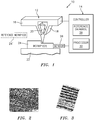
- FIG. 1 illustrates a typical additive manufacturing system 10, which has an additive manufacturing tool 12 and a controller 14.
- Additive manufacturing tool 12 has a material reservoir 16, material dispensers 18, a laser guide 20, a platform 22 for a workpiece 24, and a sensor 26 which communicates with controller 14.
- Controller 14 typically includes a reference database 28 and processor 30.
- Reference database 28 contains relevant data and processor 30 contains programming to control additive manufacturing tool 12 to produce parts as is known to a person of ordinary skill in the art.
- the present disclosure is directed to producing a process map which includes models of a process at different process parameters to produce a "virtual machine" which can be used, when loaded into or accessed by reference database 28, to produce physical parts from system 10 with the desired low crack propensity, low residual stress and microstructure properties.
- the virtual machine can also be used in advance of manufacture of actual parts to model virtual parts and estimate results at intended process parameters.
- FIG. 2 shows a measured primary dendrite arm spacing (PDAS) for a physical product in the order of 1-3 microns.
- FIG. 3 shows a phase field model predicted PDAS for a virtual structure corresponding to that of FIG. 2 , with PDAS in the order of 2-5 microns.
- the predictive model is sufficiently accurate for use in analyzing results of a virtual additive manufacturing process.
- FIG. 4 schematically illustrates the method of the present disclosure, wherein an additive manufacturing process is modeled in order to produce a process map.
- the first step is to design a part, for example typically using a computer aided design (CAD) or other approach.
- CAD computer aided design
- the design so generated can then be entered into an additive manufacturing process to produce a corresponding part.
- this design is first used with a physics-based model receiving a combination of input including part design as well as energy equation, and some combination of phase field, concentration and stress equations, to produce a series of outputs at different operating parameters. These outputs can then be compared with acceptance criteria to determine whether the output is acceptable, and can be used to produce a sufficiently defect free component, or is unacceptable. The results of this comparison can then be used to construct a process map for controlling a system such as system 10 of FIG. 1 .
- the process map includes models of process output at different process parameters.
- the process map in question can be generated, for example by following the flow chart of FIG. 4 , in a virtual environment without requirement of manufacturing any actual physical parts. Rather, the result of the flow chart of FIG. 4 is a virtual machine which can be used to produce a variety of virtual parts at different process parameters, each of which has simulated properties that can be evaluated and used to outline the various acceptable combinations of process parameters. This output helps to select suitable parameters for making actual parts.
- Operating parameters to be set and used in this process can include, for example, laser, power, beam travel speed or velocity, hatch spacing, scan width, overhang and the like, in various desired combinations.
- a physics-based model 50 receives input from boundary conditions 52 and operating parameters 54 as well as an energy equation 56, a phase field equation 58, a concentration equation 60 and a stress equation 62 and any additional criteria which may be relevant to fracture propagation such as fatigue crack propagation curve and the like.
- the boundary condition 52 and operating parameters 54 are related to the design of the part in question.
- the boundary condition is directly related to the structure of the part as well as the material from which the part is to be produced.
- the operating parameters can be set, either manually or through programming in a controller of the overall method of the present disclosure, to determine a complete process map through numerous iterations of the process.
- the energy equation is the direct relation between energy used in the process and quality of the resulting output in terms of crack propensity, residual stress and microstructure of the product.
- phase field equation is an approach to analysis of complex relationships between non-linear variables, and also deals directly with behavior of material, in liquid, solid and gaseous phases, as well as the transition of the material between these phases.
- the concentration equation is related to concentration of materials being used in the additive manufacturing process.
- the stress equation is the relationship between various complexities in the shape of the part to be manufactured and stress generated in such parts due to this shape, operating parameters and other factors including, but not limited to, thermal stress.
- model 50 receives input from a coupled solution of the energy equation 56 and at least one of the phase field equation 58, concentration equation 60 and stress equation 62, as well as the boundary condition 52 and operators 54, to produce an output 64 which includes residual stress, microstructure properties and/or crack propensity for a part manufactured according to the boundary condition and operating parameters. These outputs can then be compared (step 66) with acceptance criteria in the form of acceptable amounts of residual stress, acceptable microstructure and/or acceptable crack propensity, to determine whether the resulting output would be acceptable or unacceptable. As shown in FIG. 4 , acceptable results 68 lead to operating parameters for that boundary condition being added to a process map. Unacceptable output in step 70 leads to a manual or automated change in operating parameters and further iteration in model 50. Further, unacceptable output may also be included in the process map in order to set boundaries related to unacceptable parts as well.
- This series of steps can be carried out as many times as is necessary to generate a substantially complete process map which can then be used as a virtual machine to test theoretical production of a part, and/or can be used to control a system 10 ( FIG. 1 ) to produce actual physical parts with the benefit optimization of the process.
- output which is determined to be unacceptable can be ignored, in which case nothing further is done with that output and the process proceeds with changed parameters.
- output which is determined to be unacceptable can be added to the process map in a negative sense (i.e. a data point with bad results) to help define boundaries of specific operating parameters.
- the very complex behavior of an additive manufacturing process can be accurately modeled to produce a virtual machine.
- the virtual machine can be used to simulate production of articles, and then evaluate the properties of such simulated articles, without the actual need for preparation of physical samples to be tested and evaluated as discussed in the background section above. This leads to faster and less costly determination of acceptable process parameters as compared to conventional methods.
- experiments can be conducted as shown at step 72, and these experiments can be used for validation and calibration of model 50 as shown in step 74.
- model 50 can use input from each of the equations 56, 58, 60, 62.
- the part to be manufactured can be made by various different additive manufacturing processes, and can be made from plastics, metals, metal alloys, and other materials known for use in additive manufacturing processes. Alloys are a particularly suitable material.
- One non-limiting area of applicability of the present disclosure is in the manufacture of aircraft engine parts and components, such as gas turbine engine components.
- a model such as physics-based model 50 is constructed and programmed to estimate output of a simulated additive manufacturing process based upon part design, which can include boundary conditions and/or operating parameters.
- the model further includes energy equation and other considerations which can include phase field equation, concentration equation and stress equation.
- An initial set of operating parameters can then be entered to the model, resulting in an output in terms of residual stress, microstructure and/or crack propensity of a part manufactured at the entered parameters.
- This output can then be compared to acceptance criteria to identify acceptable output, which can be entered into a process map. Output identified as unacceptable can be ignored or used to help define boundaries of the process map.
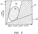
- FIG. 5 shows a non-limiting example of a process map for an additive manufacturing process.
- the process map in this case presents product results as a relation of beam travel speed (m/s) and laser power (w). Plotting the results obtained with different parameters helps to identify the most probable regions corresponding to different defects 76, 78, 80 related to melting and solidification in a laser powder bed fusion process, as well as a defect-free region 82 with the least amount of probable defects.
- another region is also highlighted which represents a hypothetical region that yields deposit with minimum cracks, residual stress and distortion. Hence, combining these two regions to identify an overlap 84 of the crack-free region and the defect free region, parameters are identified which should yield additive manufactured parts containing a minimum amount of cracks and defects.
Landscapes
- Engineering & Computer Science (AREA)
- Automation & Control Theory (AREA)
- Manufacturing & Machinery (AREA)
- Chemical & Material Sciences (AREA)
- Materials Engineering (AREA)
- Physics & Mathematics (AREA)
- General Physics & Mathematics (AREA)
- Artificial Intelligence (AREA)
- Evolutionary Computation (AREA)
- Medical Informatics (AREA)
- Software Systems (AREA)
- Computer Vision & Pattern Recognition (AREA)
- Health & Medical Sciences (AREA)
- Human Computer Interaction (AREA)
- Powder Metallurgy (AREA)
Abstract
Description
- The present disclosure relates generally to additive manufacturing and, more particularly to a method for modeling additive manufacturing of a part to reduce crack propensity and residual stress.
- Powder bed and directed energy additive manufacturing techniques are becoming more widely adopted for production of complex near-net-shape parts. Additive manufacturing offers increased design freedom and enables designers and engineers to create unique products.
- Despite the advance of such technology, the challenge remains to repeatedly produce high quality components with minimal distortion, minimal residual stress and little or no amount of cracking and other defects. These issues are currently addressed by conducting expensive time and resource intensive experimentation whereby a component is produced and then analyzed using a trial and error approach, with results of the analysis leading to adjustments for the next attempt.
- Energy-based approaches have been attempted and provide fast-acting process maps that result in correct computation of required energy density for sufficient melting of feedstock powders, and also for avoidance of the formation of pores. However, crack propensity in articles manufactured through additive manufacturing is highly non-linear, and the energy-based analysis is therefore in need of further improvement.
- According to the disclosure a method for modeling additive manufacturing of a part comprises the steps of:
(i) constructing a model for estimating output of a simulated additive manufacturing process based upon part design, energy equation and at least one additional relationship selected from the group consisting of phase field equation, concentration equation and stress equation; (ii) entering process operating parameters into the model to produce an output; (iii) comparing the output to acceptance criteria to determine whether the output is acceptable or unacceptable; (iv) for acceptable output, adding operating parameters, which resulted in the acceptable output, to a process map for additive manufacturing the part; and (v) repeating steps (ii) through (iv) for different operating parameters until the process map is complete. - In a further non-limiting embodiment of the method, the output comprises an estimate of at least one of residual stress, microstructure and crack propensity of the part.
- In a further non-limiting embodiment of the method, the model estimates output based upon the part design, energy equation, phase field equation, concentration equation and stress equation, and wherein the output comprises residual stress, microstructure and crack propensity of the part.
- In a further non-limiting embodiment of the method, the part is a near net complex shaped part.
- In a further non-limiting embodiment of the method, the model comprises a coupled solution of the energy equation and the at least one additional relationship.
- In a further non-limiting embodiment of the method, the model comprises a coupled solution of the energy equation, the phase field equation, the concentration equation and the stress equation.
- In a further non-limiting embodiment, the process map is used to produce a physical part.
- A further non-limiting embodiment of the method comprises validating and calibrating the process model based upon characteristics of the physical part.
- In a further non-limiting embodiment of the method, unacceptable output is not added to the process map.
- In a further non-limiting embodiment of the method, unacceptable output is added to the process map to set boundaries related to unacceptable parts.
- In a further non-limiting embodiment of the method, the operating parameters comprise laser, power, beam travel speed or velocity, hatch spacing, scan width and overhang.
- In a further non-limiting embodiment of the method, the part is produced from an alloy.
- In a further non-limiting embodiment, a method for additive manufacturing of a part comprises entering a part design into an additive manufacturing system programmed with a process map developed from part design, energy equation and at least one additional relationship selected from the group consisting of phase field equation, concentration equation and stress equation to produce a part according to the part design and the process map.
- In a further non-limiting embodiment of this method, the part is a near net complex shaped part.
- In a further non-limiting embodiment of this method, the part is produced from an alloy.
- In a further non-limiting embodiment, a system for additive manufacturing of a part comprises an additive manufacturing system comprising a control unit programmed with a process map developed from a part design, energy equation and at least one additional relationship selected from the group consisting of phase field equation, concentration equation and stress equation to produce a part according to the part design and the process map, wherein said control unit is further programmed to operate an additive manufacturing machine at process parameters within the process map.
- A detailed description follows, with reference to the attached drawings, wherein:
-
FIG. 1 schematically illustrates an additive manufacturing system; -
FIGS. 2 and 3 show measured and phase-field model predicted primary dendrite arm spacings (PDAS) of an additive manufactured article; -
FIG. 4 is a flow chart illustrating the method of the present disclosure; and -
FIG. 5 schematically illustrates a process map produced in accordance with the present disclosure. - The present disclosure relates to the field of additive manufacturing and, more particularly, to a method for modeling an additive manufacturing process models at different process in order to develop a process map or series of process models at different process parameters which can be used to produce actual physical products or workpieces with reduced crack propensity, reduced residual stress and a desirable microstructure.
-
FIG. 1 illustrates a typicaladditive manufacturing system 10, which has anadditive manufacturing tool 12 and acontroller 14.Additive manufacturing tool 12 has amaterial reservoir 16,material dispensers 18, alaser guide 20, aplatform 22 for aworkpiece 24, and asensor 26 which communicates withcontroller 14. -
Controller 14 typically includes areference database 28 andprocessor 30.Reference database 28 contains relevant data andprocessor 30 contains programming to controladditive manufacturing tool 12 to produce parts as is known to a person of ordinary skill in the art. - The present disclosure is directed to producing a process map which includes models of a process at different process parameters to produce a "virtual machine" which can be used, when loaded into or accessed by
reference database 28, to produce physical parts fromsystem 10 with the desired low crack propensity, low residual stress and microstructure properties. The virtual machine can also be used in advance of manufacture of actual parts to model virtual parts and estimate results at intended process parameters. - Characteristics of a resulting product or workpiece from an additive manufacturing process can be accurately simulated and predicted. For example,
FIG. 2 shows a measured primary dendrite arm spacing (PDAS) for a physical product in the order of 1-3 microns.FIG. 3 shows a phase field model predicted PDAS for a virtual structure corresponding to that ofFIG. 2 , with PDAS in the order of 2-5 microns. Thus, the predictive model is sufficiently accurate for use in analyzing results of a virtual additive manufacturing process. -
FIG. 4 schematically illustrates the method of the present disclosure, wherein an additive manufacturing process is modeled in order to produce a process map. - In a typical additive manufacturing process, the first step is to design a part, for example typically using a computer aided design (CAD) or other approach. The design so generated can then be entered into an additive manufacturing process to produce a corresponding part. In accordance with the present disclosure, however, this design is first used with a physics-based model receiving a combination of input including part design as well as energy equation, and some combination of phase field, concentration and stress equations, to produce a series of outputs at different operating parameters. These outputs can then be compared with acceptance criteria to determine whether the output is acceptable, and can be used to produce a sufficiently defect free component, or is unacceptable. The results of this comparison can then be used to construct a process map for controlling a system such as
system 10 ofFIG. 1 . As discussed above, the process map includes models of process output at different process parameters. Significantly, the process map in question can be generated, for example by following the flow chart ofFIG. 4 , in a virtual environment without requirement of manufacturing any actual physical parts. Rather, the result of the flow chart ofFIG. 4 is a virtual machine which can be used to produce a variety of virtual parts at different process parameters, each of which has simulated properties that can be evaluated and used to outline the various acceptable combinations of process parameters. This output helps to select suitable parameters for making actual parts. - Operating parameters to be set and used in this process can include, for example, laser, power, beam travel speed or velocity, hatch spacing, scan width, overhang and the like, in various desired combinations.
- As shown in
FIG. 4 , a physics-basedmodel 50 receives input fromboundary conditions 52 andoperating parameters 54 as well as anenergy equation 56, aphase field equation 58, aconcentration equation 60 and astress equation 62 and any additional criteria which may be relevant to fracture propagation such as fatigue crack propagation curve and the like. - The
boundary condition 52 andoperating parameters 54 are related to the design of the part in question. The boundary condition is directly related to the structure of the part as well as the material from which the part is to be produced. The operating parameters can be set, either manually or through programming in a controller of the overall method of the present disclosure, to determine a complete process map through numerous iterations of the process. - The energy equation is the direct relation between energy used in the process and quality of the resulting output in terms of crack propensity, residual stress and microstructure of the product.
- The phase field equation is an approach to analysis of complex relationships between non-linear variables, and also deals directly with behavior of material, in liquid, solid and gaseous phases, as well as the transition of the material between these phases.
- The concentration equation is related to concentration of materials being used in the additive manufacturing process.
- Finally, the stress equation is the relationship between various complexities in the shape of the part to be manufactured and stress generated in such parts due to this shape, operating parameters and other factors including, but not limited to, thermal stress.
- According to the present disclosure,
model 50 receives input from a coupled solution of theenergy equation 56 and at least one of thephase field equation 58,concentration equation 60 andstress equation 62, as well as theboundary condition 52 andoperators 54, to produce anoutput 64 which includes residual stress, microstructure properties and/or crack propensity for a part manufactured according to the boundary condition and operating parameters. These outputs can then be compared (step 66) with acceptance criteria in the form of acceptable amounts of residual stress, acceptable microstructure and/or acceptable crack propensity, to determine whether the resulting output would be acceptable or unacceptable. As shown inFIG. 4 ,acceptable results 68 lead to operating parameters for that boundary condition being added to a process map. Unacceptable output instep 70 leads to a manual or automated change in operating parameters and further iteration inmodel 50. Further, unacceptable output may also be included in the process map in order to set boundaries related to unacceptable parts as well. - This series of steps can be carried out as many times as is necessary to generate a substantially complete process map which can then be used as a virtual machine to test theoretical production of a part, and/or can be used to control a system 10 (
FIG. 1 ) to produce actual physical parts with the benefit optimization of the process. - Still referring to
FIG. 4 , it should be appreciated that the output which is determined to be unacceptable can be ignored, in which case nothing further is done with that output and the process proceeds with changed parameters. Alternatively, output which is determined to be unacceptable can be added to the process map in a negative sense (i.e. a data point with bad results) to help define boundaries of specific operating parameters. - By producing a model which combines the various conditions and equations as discussed above, the very complex behavior of an additive manufacturing process can be accurately modeled to produce a virtual machine. The virtual machine can be used to simulate production of articles, and then evaluate the properties of such simulated articles, without the actual need for preparation of physical samples to be tested and evaluated as discussed in the background section above. This leads to faster and less costly determination of acceptable process parameters as compared to conventional methods.
- Still referring to
FIG. 4 , once a suitable process map has been determined, experiments can be conducted as shown atstep 72, and these experiments can be used for validation and calibration ofmodel 50 as shown instep 74. - In one non-limiting embodiment,
model 50 can use input from each of theequations - Further, the part to be manufactured can be made by various different additive manufacturing processes, and can be made from plastics, metals, metal alloys, and other materials known for use in additive manufacturing processes. Alloys are a particularly suitable material.
- One non-limiting area of applicability of the present disclosure is in the manufacture of aircraft engine parts and components, such as gas turbine engine components.
- Following the method outlined in
FIG. 4 , a method is provided wherein a process map for additive manufacturing is produced. - Initially, a model such as physics-based
model 50 is constructed and programmed to estimate output of a simulated additive manufacturing process based upon part design, which can include boundary conditions and/or operating parameters. The model further includes energy equation and other considerations which can include phase field equation, concentration equation and stress equation. - An initial set of operating parameters can then be entered to the model, resulting in an output in terms of residual stress, microstructure and/or crack propensity of a part manufactured at the entered parameters.
- This output can then be compared to acceptance criteria to identify acceptable output, which can be entered into a process map. Output identified as unacceptable can be ignored or used to help define boundaries of the process map.
- These steps can then be repeated as necessary, with the model being adapted to parameters used, until a sufficiently complete process map has been generated.
-
FIG. 5 shows a non-limiting example of a process map for an additive manufacturing process. The process map in this case presents product results as a relation of beam travel speed (m/s) and laser power (w). Plotting the results obtained with different parameters helps to identify the most probable regions corresponding todifferent defects free region 82 with the least amount of probable defects. On the same plot, another region is also highlighted which represents a hypothetical region that yields deposit with minimum cracks, residual stress and distortion. Hence, combining these two regions to identify anoverlap 84 of the crack-free region and the defect free region, parameters are identified which should yield additive manufactured parts containing a minimum amount of cracks and defects. - The present disclosure provides a novel and non-obvious method and system for one or more embodiments of the present disclosure have been described. Variations and modifications to the disclosed examples may become apparent to those skilled in the art that do not necessarily depart from the essence of this disclosure. For example, the exact combinations of virtual parameters to be used in constructing and optimizing the model can be any combination of factors as listed, and could be combined with additional factors as well. Accordingly, other embodiments are within the scope of the following claims.
Claims (15)
- A method for modeling additive manufacturing of a part, comprising the steps of:(i) constructing a model (50) for estimating output (64) of a simulated additive manufacturing process based upon part design, energy equation (56) and at least one additional relationship selected from the group consisting of phase field equation (58), concentration equation (60) and stress equation (62) ;(ii) entering process operating parameters (54) into the model (50) to produce an output (64);(iii) comparing the output (64) to acceptance criteria (66) to determine whether the output (64) is acceptable (68) or unacceptable (70);(iv) for acceptable output (68), adding operating parameters (54), which resulted in the acceptable output (68), to a process map for additive manufacturing the part; and(v) repeating steps (ii) through (iv) for different operating parameters (54) until the process map is complete.
- The method of claim 1, wherein the output (64) comprises an estimate of at least one of residual stress, microstructure and crack propensity of the part.
- The method of claim 1 or 2, wherein the model (50) estimates output (64) based upon the part design, energy equation (56), phase field equation (58), concentration equation (60) and stress equation (62), and the output (64) comprises residual stress, microstructure and crack propensity of the part.
- The method of claim 1, 2 or 3, wherein the part is a near net complex shaped part.
- The method of any preceding claim, wherein the model (50) comprises a coupled solution of the energy equation (56) and the at least one additional relationship.
- The method of any of claims 1 to 4, wherein the model (50) comprises a coupled solution of the energy equation (56), the phase field equation (58), the concentration equation (60) and the stress equation (62).
- The method of any preceding claim, further comprising using the process map to produce a physical part.
- The process of claim 7, further comprising validating and calibrating (74) the model (50) based upon characteristics of the physical part.
- The method of any preceding claim, wherein unacceptable output (70) is not added to the process map.
- The method of any of claims 1 to 8, wherein unacceptable output (70) is added to the process map to set boundaries related to unacceptable parts.
- The method of any preceding claim, wherein the operating parameters (54) comprise laser, power, beam travel speed or velocity, hatch spacing, scan width and overhang.
- A method for additive manufacturing of a part, comprising entering a part design into an additive manufacturing system (10) programmed with a process map developed from part design, energy equation (56) and at least one additional relationship selected from the group consisting of phase field equation (58), concentration equation (60) and stress equation (62) to produce a part according to the part design and the process map.
- The method of claim 12, wherein the part is a near net complex shaped part.
- The method of any preceding claim, wherein the part is produced from an alloy.
- A system for additive manufacturing of a part, comprising an additive manufacturing system (10) comprising a control unit (14) programmed with a process map developed from a part design, energy equation (56) and at least one additional relationship selected from the group consisting of phase field equation (58), concentration equation (60) and stress equation (62) to produce a part according to the part design and the process map, wherein said control unit (14) is further programmed to operate an additive manufacturing machine (12) at process parameters within the process map.
Applications Claiming Priority (1)
| Application Number | Priority Date | Filing Date | Title |
|---|---|---|---|
| US15/621,104 US20180356778A1 (en) | 2017-06-13 | 2017-06-13 | Method for modeling additive manufacturing of a part |
Publications (1)
| Publication Number | Publication Date |
|---|---|
| EP3416008A1 true EP3416008A1 (en) | 2018-12-19 |
Family
ID=62778670
Family Applications (1)
| Application Number | Title | Priority Date | Filing Date |
|---|---|---|---|
| EP18176982.9A Withdrawn EP3416008A1 (en) | 2017-06-13 | 2018-06-11 | Method for modeling additive manufacturing of a part |
Country Status (2)
| Country | Link |
|---|---|
| US (1) | US20180356778A1 (en) |
| EP (1) | EP3416008A1 (en) |
Cited By (1)
| Publication number | Priority date | Publication date | Assignee | Title |
|---|---|---|---|---|
| CN111290283A (en) * | 2020-04-03 | 2020-06-16 | 福州大学 | A single machine scheduling method for additive manufacturing for selective laser melting process |
Families Citing this family (13)
| Publication number | Priority date | Publication date | Assignee | Title |
|---|---|---|---|---|
| US10073440B1 (en) * | 2018-02-13 | 2018-09-11 | University Of Central Florida Research Foundation, Inc. | Method for the design and manufacture of composites having tunable physical properties |
| EP3671373A1 (en) * | 2018-12-19 | 2020-06-24 | Bystronic Laser AG | Forecasting method for predicting the machining result for a laser machining method |
| CN114026510B (en) * | 2019-03-29 | 2024-02-13 | 西门子能源全球有限两合公司 | Methods and systems for optimizing process parameters in additive manufacturing processes |
| CN111203538B (en) * | 2020-04-22 | 2020-07-28 | 中国航发上海商用航空发动机制造有限责任公司 | Prefabricated crack defect, preparation method of built-in crack defect and prefabricated part |
| CN111203539B (en) * | 2020-04-22 | 2020-07-28 | 中国航发上海商用航空发动机制造有限责任公司 | Preparation method of prefabricated air hole defect and built-in air hole defect and prefabricated part |
| CN111203537B (en) * | 2020-04-22 | 2020-07-28 | 中国航发上海商用航空发动机制造有限责任公司 | Method for prefabricating fusion defect by controlling L MD process |
| US11531920B2 (en) * | 2020-04-27 | 2022-12-20 | Raytheon Technologies Corporation | System and process for verifying powder bed fusion additive manufacturing operation as being defect free |
| US20220032549A1 (en) * | 2020-07-30 | 2022-02-03 | General Electric Company | Additive manufacturing systems and methods including build characteristic contribution profile |
| US12005498B2 (en) | 2020-07-31 | 2024-06-11 | General Electric Company | Additive manufacturing systems and methods including build characteristic contribution profiles |
| CN112257301B (en) * | 2020-08-13 | 2022-08-09 | 唐山钢铁集团有限责任公司 | Method for improving sheet stamping qualification rate by adopting real die digital-analog simulation analysis |
| US20220108051A1 (en) * | 2020-10-06 | 2022-04-07 | Sentient Science Corporation | Systems and methods for modeling performance in a part manufactured using an additive manufacturing process |
| CN114872324B (en) * | 2022-04-15 | 2023-09-29 | 华中科技大学 | A laser additive manufacturing method based on multi-dimensional information coupling control performance |
| US12554245B2 (en) * | 2022-09-15 | 2026-02-17 | Baker Hughes Oilfield Operations Llc | Machine learning based rapid parameter development for additive manufacturing and related methods |
Citations (4)
| Publication number | Priority date | Publication date | Assignee | Title |
|---|---|---|---|---|
| US20100174392A1 (en) * | 2003-06-10 | 2010-07-08 | Fink Jeffrey E | Optimal dimensional and mechanical properties of laser sintered hardware by thermal analysis and parameter optimization |
| US8655476B2 (en) * | 2011-03-09 | 2014-02-18 | GM Global Technology Operations LLC | Systems and methods for computationally developing manufacturable and durable cast components |
| US20150331402A1 (en) * | 2014-05-13 | 2015-11-19 | Autodesk, Inc. | Intelligent 3d printing through optimization of 3d print parameters |
| US20160107393A1 (en) * | 2013-04-26 | 2016-04-21 | ubimake GmbH | Optimization of a production process |
-
2017
- 2017-06-13 US US15/621,104 patent/US20180356778A1/en not_active Abandoned
-
2018
- 2018-06-11 EP EP18176982.9A patent/EP3416008A1/en not_active Withdrawn
Patent Citations (4)
| Publication number | Priority date | Publication date | Assignee | Title |
|---|---|---|---|---|
| US20100174392A1 (en) * | 2003-06-10 | 2010-07-08 | Fink Jeffrey E | Optimal dimensional and mechanical properties of laser sintered hardware by thermal analysis and parameter optimization |
| US8655476B2 (en) * | 2011-03-09 | 2014-02-18 | GM Global Technology Operations LLC | Systems and methods for computationally developing manufacturable and durable cast components |
| US20160107393A1 (en) * | 2013-04-26 | 2016-04-21 | ubimake GmbH | Optimization of a production process |
| US20150331402A1 (en) * | 2014-05-13 | 2015-11-19 | Autodesk, Inc. | Intelligent 3d printing through optimization of 3d print parameters |
Cited By (2)
| Publication number | Priority date | Publication date | Assignee | Title |
|---|---|---|---|---|
| CN111290283A (en) * | 2020-04-03 | 2020-06-16 | 福州大学 | A single machine scheduling method for additive manufacturing for selective laser melting process |
| CN111290283B (en) * | 2020-04-03 | 2021-07-27 | 福州大学 | A single machine scheduling method for additive manufacturing for selective laser melting process |
Also Published As
| Publication number | Publication date |
|---|---|
| US20180356778A1 (en) | 2018-12-13 |
Similar Documents
| Publication | Publication Date | Title |
|---|---|---|
| EP3416008A1 (en) | Method for modeling additive manufacturing of a part | |
| EP3760341B1 (en) | Commercial scale casting process including optimization via multi-fidelity optimization | |
| Krol et al. | Prioritization of process parameters for an efficient optimisation of additive manufacturing by means of a finite element method | |
| EP3580619B1 (en) | Method and apparatus for robust reduction of shape error in laser powder deposition based additive manufacturing process due to uncertainty | |
| Wynn et al. | Modelling the evolution of uncertainty levels during design | |
| CN112580228B (en) | Fan blade structural design optimization method for mixed structure of turbofan engine | |
| Sata et al. | Bayesian inference-based investment-casting defect analysis system for industrial application | |
| Xiao et al. | Porosity management and control in powder bed fusion process through process-quality interactions | |
| CN114626263B (en) | A numerical simulation method for short crack growth in high-temperature alloy materials based on crystal plasticity | |
| Mazzucato et al. | Recent advances toward the industrialization of metal additive manufacturing | |
| EP4301544A1 (en) | Anomaly detection in additive manufacturing using meltpool monitoring, and related devices and systems | |
| Gondkar et al. | Optimization of casting process parameters through simulation | |
| Rokicki et al. | The assessment of geometric accuracy of aircraft engine blades with the use of an optical coordinate scanner | |
| Fu et al. | Streamlined frameworks for advancing metal based additive manufacturing technologies | |
| Denkena et al. | Technological simulation of the resulting bead geometry in the WAAM process using a machine learning model | |
| Ferreira et al. | Off-line programming of a flexible and adaptive production line for composite-metal multi-material manufacturing based on OPC-UA communication | |
| Riano et al. | Feedback strategy for closed-loop inspection based on STEP-NC | |
| Knüttel et al. | Height prediction in directed metal deposition with artificial neural networks | |
| Di Angelo et al. | An advanced GCode analyser for predicting the build time for additive manufacturing components | |
| KR100708758B1 (en) | How to consistently and automate NC data generation tasks | |
| Ben Amor et al. | Dimensional deviation prediction model based on scale and material concentration effects for LPBF process | |
| Bacciaglia et al. | FDM printing time prediction tuning through a DOE approach | |
| Tryhubov et al. | Numerical modeling and Digital Twins in Wire Arc Additive Manufacturing | |
| Maier et al. | Methodology for element selection and clustering in multi-axis directed energy deposition simulation | |
| US20250128330A1 (en) | Location-specific probabilistic approach for prediction of defect formation in additive manufacturing |
Legal Events
| Date | Code | Title | Description |
|---|---|---|---|
| PUAI | Public reference made under article 153(3) epc to a published international application that has entered the european phase |
Free format text: ORIGINAL CODE: 0009012 |
|
| STAA | Information on the status of an ep patent application or granted ep patent |
Free format text: STATUS: THE APPLICATION HAS BEEN PUBLISHED |
|
| AK | Designated contracting states |
Kind code of ref document: A1 Designated state(s): AL AT BE BG CH CY CZ DE DK EE ES FI FR GB GR HR HU IE IS IT LI LT LU LV MC MK MT NL NO PL PT RO RS SE SI SK SM TR |
|
| AX | Request for extension of the european patent |
Extension state: BA ME |
|
| STAA | Information on the status of an ep patent application or granted ep patent |
Free format text: STATUS: REQUEST FOR EXAMINATION WAS MADE |
|
| 17P | Request for examination filed |
Effective date: 20190619 |
|
| RBV | Designated contracting states (corrected) |
Designated state(s): AL AT BE BG CH CY CZ DE DK EE ES FI FR GB GR HR HU IE IS IT LI LT LU LV MC MK MT NL NO PL PT RO RS SE SI SK SM TR |
|
| STAA | Information on the status of an ep patent application or granted ep patent |
Free format text: STATUS: EXAMINATION IS IN PROGRESS |
|
| 17Q | First examination report despatched |
Effective date: 20201127 |
|
| STAA | Information on the status of an ep patent application or granted ep patent |
Free format text: STATUS: THE APPLICATION HAS BEEN WITHDRAWN |
|
| 18W | Application withdrawn |
Effective date: 20210108 |