EP3415893A1 - Evaluation method of impact test and impact tester - Google Patents
Evaluation method of impact test and impact tester Download PDFInfo
- Publication number
- EP3415893A1 EP3415893A1 EP18177789.7A EP18177789A EP3415893A1 EP 3415893 A1 EP3415893 A1 EP 3415893A1 EP 18177789 A EP18177789 A EP 18177789A EP 3415893 A1 EP3415893 A1 EP 3415893A1
- Authority
- EP
- European Patent Office
- Prior art keywords
- data
- impact
- section
- test
- force
- Prior art date
- Legal status (The legal status is an assumption and is not a legal conclusion. Google has not performed a legal analysis and makes no representation as to the accuracy of the status listed.)
- Withdrawn
Links
Images




Classifications
-
- G—PHYSICS
- G01—MEASURING; TESTING
- G01N—INVESTIGATING OR ANALYSING MATERIALS BY DETERMINING THEIR CHEMICAL OR PHYSICAL PROPERTIES
- G01N29/00—Investigating or analysing materials by the use of ultrasonic, sonic or infrasonic waves; Visualisation of the interior of objects by transmitting ultrasonic or sonic waves through the object
- G01N29/04—Analysing solids
- G01N29/045—Analysing solids by imparting shocks to the workpiece and detecting the vibrations or the acoustic waves caused by the shocks
-
- G—PHYSICS
- G01—MEASURING; TESTING
- G01N—INVESTIGATING OR ANALYSING MATERIALS BY DETERMINING THEIR CHEMICAL OR PHYSICAL PROPERTIES
- G01N3/00—Investigating strength properties of solid materials by application of mechanical stress
- G01N3/30—Investigating strength properties of solid materials by application of mechanical stress by applying a single impulsive force, e.g. by falling weight
- G01N3/307—Investigating strength properties of solid materials by application of mechanical stress by applying a single impulsive force, e.g. by falling weight generated by a compressed or tensile-stressed spring; generated by pneumatic or hydraulic means
-
- G—PHYSICS
- G01—MEASURING; TESTING
- G01N—INVESTIGATING OR ANALYSING MATERIALS BY DETERMINING THEIR CHEMICAL OR PHYSICAL PROPERTIES
- G01N29/00—Investigating or analysing materials by the use of ultrasonic, sonic or infrasonic waves; Visualisation of the interior of objects by transmitting ultrasonic or sonic waves through the object
- G01N29/36—Detecting the response signal, e.g. electronic circuits specially adapted therefor
- G01N29/42—Detecting the response signal, e.g. electronic circuits specially adapted therefor by frequency filtering or by tuning to resonant frequency
-
- G—PHYSICS
- G01—MEASURING; TESTING
- G01N—INVESTIGATING OR ANALYSING MATERIALS BY DETERMINING THEIR CHEMICAL OR PHYSICAL PROPERTIES
- G01N29/00—Investigating or analysing materials by the use of ultrasonic, sonic or infrasonic waves; Visualisation of the interior of objects by transmitting ultrasonic or sonic waves through the object
- G01N29/44—Processing the detected response signal, e.g. electronic circuits specially adapted therefor
- G01N29/46—Processing the detected response signal, e.g. electronic circuits specially adapted therefor by spectral analysis, e.g. Fourier analysis or wavelet analysis
-
- G—PHYSICS
- G01—MEASURING; TESTING
- G01N—INVESTIGATING OR ANALYSING MATERIALS BY DETERMINING THEIR CHEMICAL OR PHYSICAL PROPERTIES
- G01N3/00—Investigating strength properties of solid materials by application of mechanical stress
- G01N3/02—Details
- G01N3/06—Special adaptations of indicating or recording means
- G01N3/066—Special adaptations of indicating or recording means with electrical indicating or recording means
-
- G—PHYSICS
- G01—MEASURING; TESTING
- G01N—INVESTIGATING OR ANALYSING MATERIALS BY DETERMINING THEIR CHEMICAL OR PHYSICAL PROPERTIES
- G01N3/00—Investigating strength properties of solid materials by application of mechanical stress
- G01N3/30—Investigating strength properties of solid materials by application of mechanical stress by applying a single impulsive force, e.g. by falling weight
-
- G—PHYSICS
- G01—MEASURING; TESTING
- G01N—INVESTIGATING OR ANALYSING MATERIALS BY DETERMINING THEIR CHEMICAL OR PHYSICAL PROPERTIES
- G01N3/00—Investigating strength properties of solid materials by application of mechanical stress
- G01N3/62—Manufacturing, calibrating, or repairing devices used in investigations covered by the preceding subgroups
-
- G—PHYSICS
- G01—MEASURING; TESTING
- G01N—INVESTIGATING OR ANALYSING MATERIALS BY DETERMINING THEIR CHEMICAL OR PHYSICAL PROPERTIES
- G01N2203/00—Investigating strength properties of solid materials by application of mechanical stress
- G01N2203/0014—Type of force applied
- G01N2203/0016—Tensile or compressive
- G01N2203/0017—Tensile
-
- G—PHYSICS
- G01—MEASURING; TESTING
- G01N—INVESTIGATING OR ANALYSING MATERIALS BY DETERMINING THEIR CHEMICAL OR PHYSICAL PROPERTIES
- G01N2203/00—Investigating strength properties of solid materials by application of mechanical stress
- G01N2203/003—Generation of the force
- G01N2203/0042—Pneumatic or hydraulic means
- G01N2203/0048—Hydraulic means
-
- G—PHYSICS
- G01—MEASURING; TESTING
- G01N—INVESTIGATING OR ANALYSING MATERIALS BY DETERMINING THEIR CHEMICAL OR PHYSICAL PROPERTIES
- G01N2203/00—Investigating strength properties of solid materials by application of mechanical stress
- G01N2203/02—Details not specific for a particular testing method
- G01N2203/0202—Control of the test
- G01N2203/021—Treatment of the signal; Calibration
-
- G—PHYSICS
- G01—MEASURING; TESTING
- G01N—INVESTIGATING OR ANALYSING MATERIALS BY DETERMINING THEIR CHEMICAL OR PHYSICAL PROPERTIES
- G01N2203/00—Investigating strength properties of solid materials by application of mechanical stress
- G01N2203/02—Details not specific for a particular testing method
- G01N2203/06—Indicating or recording means; Sensing means
- G01N2203/067—Parameter measured for estimating the property
- G01N2203/0688—Time or frequency
-
- G—PHYSICS
- G01—MEASURING; TESTING
- G01N—INVESTIGATING OR ANALYSING MATERIALS BY DETERMINING THEIR CHEMICAL OR PHYSICAL PROPERTIES
- G01N2291/00—Indexing codes associated with group G01N29/00
- G01N2291/01—Indexing codes associated with the measuring variable
- G01N2291/014—Resonance or resonant frequency
Definitions
- the disclosure relates to an evaluation method of an impact test in which force at the time when an impact is rapidly applied to a test piece is detected by a force detector, and to an impact tester.
- a tensile impact test (JIS K 7160 "Plastics - Determination of Tensile-Impact Strength”) measuring energy at the time when a test piece is broken by a tensile impact at a specified speed, or a puncture impact test (JIS K 7211-2 "Plastics - Determination of Puncture Impact Behavior of Rigid Plastics”) causing a striker to vertically collide with a surface of a test piece to obtain an impact force-displacement diagram, or the like, may be used.
- both ends of the test piece are gripped by upper and lower grippers, the upper gripper is driven by a hydraulic cylinder at high speed to stretch the test piece, and impact force at breakage of the test piece is detected by a load cell (see Japanese Laid-open No. 2004-333221 ).
- a hydraulic cylinder causes a punch to collide with the test piece at high speed to damage the test piece, and impact force at that time is detected by a detector (see Japanese Laid-open No. 2004-333143 ).
- vibration that occurs when the test piece breaks or vibration that occurs when the punch collides with the test piece may extend over the entire impact tester.
- noise caused by natural vibration of the impact tester is added to a force waveform.
- a natural frequency of the impact tester In order to know an accurate force value, it is important to know a natural frequency of the impact tester.
- the test jig is connected to a force detector, vibration waveform data generated by striking the test jig by a hammer or the like is acquired, and a frequency spectrum analysis is carried out on the waveform.
- a striking object such as the hammer or the like
- an acceleration sensor, an oscilloscope, a data logger and so on that are for collecting the vibration waveform data, apart from collecting data of a normal test performed by operating the impact tester.
- a user is required to correctly connect and operate the machines and a problem arises that the preparation is messy and takes time.
- the disclosure provides an evaluation method of an impact test and an impact tester, capable of simply and accurately obtaining a natural frequency of the impact tester without adding a special machine for measuring the natural frequency of the impact tester.
- an evaluation method of an impact test in which an impact is rapidly applied to a test piece includes: a data extraction step in which a data section for obtaining a natural frequency of an impact tester is extracted from time-series data detected by a force detector by carrying out the impact test, in the data extraction step, the time-series data is separated before and after force is removed from the test piece, and data after the force is removed from the test piece is used as the data section for obtaining the natural frequency of the impact tester; and an analysis step in which a frequency spectrum analysis is carried out on the data section extracted in the data extraction step.
- an impact tester rapidly applying an impact to a test piece includes: a load structure, applying force to the test piece; a force detector, detecting the force applied to the test piece; and a control device, including a memory section storing time-series data detected by the force detector, wherein the control device includes: a data extraction section, extracting from the time-series data stored in the memory section a data section for obtaining a natural frequency of the impact tester; and an analysis section, carrying out a frequency spectrum analysis on the data section extracted in the data extraction section.
- the natural frequency of the impact tester from the force data detected by the force detector when the impact test is carried out.
- a complicated operation of connecting the additional machine may be omitted, and the impact tester will not become expensive because of the additional machine.
- FIG. 1 is a schematic diagram of an impact tester according to the disclosure.
- FIG. 2 is a block diagram explaining a main control system of the impact tester according to the disclosure.
- the impact tester carries out an impact test rapidly applying an impact to a test piece TP, and includes a tester body 10 and a control device 40.
- the tester body 10 includes a table 11, a pair of support posts 12 erected on the table 11, a cross yoke 13 bridged over the pair of support posts 12, and a hydraulic cylinder 31 fixed to the cross yoke 13.
- the hydraulic cylinder 31 is operated by operating oil supplied via a servo valve 34 from a hydraulic source (not illustrated) disposed in the table 11.
- An upper gripper 21 is connected to a piston rod 32 of the hydraulic cylinder 31 via an approach jig 25 and a joint 26.
- a lower gripper 22 is connected to the table 11 via a load cell 27 being a force detector.
- the configuration of the tester body 10 is a configuration for carrying out a tensile impact test in which, by providing an approach section in a tensile direction by the approach jig 25 and pulling up the piston rod 32 at a high speed of 0.1 m/s to 20 m/s, a pair of grippers that grip both ends of the test piece TP are rapidly separated.
- a displacement (stroke) of a load structure, i.e., a movement amount of the piston rod 32, at the time when the tensile impact test is carried out is detected by a stroke sensor 33, and force at that time is detected by the load cell 27.
- the control device 40 includes a body control device 41 for controlling operation of the tester body 10, and a personal computer 42.
- the body control device 41 includes a memory 43 storing programs, an arithmetic device 45 such as a micro processing unit (MPU) or the like performing various operations, and a communication section 46 communicating with the personal computer 42.
- the memory 43, the arithmetic device 45 and the communication section 46 are connected to one another by a bus 61.
- the body control device 41 includes a test control section 44 as a functional configuration.
- the test control section 44 is stored as a test control program in the memory 43.
- the personal computer 42 includes a memory 51 consisting of a read-only memory (ROM) that stores a data analysis program, a random access memory (RAM) that loads a program and temporarily stores data when executing the program and so on, an arithmetic device 55 such as a central processing unit (CPU) or the like performing various operations, a communication section 56 communicating with an external connection machine such as the body control device 41 or the like, a memory device 57 storing data, a display device 58 and an input device 59.
- the memory device 57 is a memory section storing time-series data of force of an impact test and so on, and is composed of a large capacity memory device such as a hard disk drive (HDD) or the like.
- the memory 51, the arithmetic device 55, the communication section 56, the memory device 57, the display device 58 and the input device 59 are connected to one another by a bus 71.
- the personal computer 42 includes, as a functional configuration, a data extraction section 52 extracting from the time-series data of the force a data section for obtaining a natural frequency of the impact tester in a later-described natural vibration analysis, and an analysis section 53 carrying out a frequency spectrum analysis on the extracted data section.
- the data extraction section 52 and the analysis section 53 are respectively stored as a data extraction program and an analysis program in the memory 51. These programs are executed due to the action of the arithmetic device 55.
- the force detected by the load cell 27 when the tensile impact test is carried out is input to the memory 43 of the body control device 41, and then sent from the communication section 46 to the personal computer 42.
- the force received by the communication section 56 of the personal computer 42 is stored as time-series data in the memory device 57.
- FIG. 3 is a flowchart showing a natural vibration measurement procedure. This flowchart shows the measurement procedure of the natural vibration in a tensile impact test using a synthetic resin piece such as polypropylene (PP), polycarbonate (PC), polystyrene (PS) or the like as the test piece TP.
- a synthetic resin piece such as polypropylene (PP), polycarbonate (PC), polystyrene (PS) or the like as the test piece TP.
- test conditions are set (step S11).
- a user sets the test conditions such as test speed and so on using the input device 59 of the personal computer 42.
- both ends of the test piece TP are gripped by the upper gripper 21 and the lower gripper 22 (step S12).
- step S13 data acquisition conditions are set.
- the user sets data collection conditions, such as data collection start time and data collection end time, sampling frequency, number of acquired data points (number of sampling points) and so on, using the input device 59 of the personal computer 42.
- the natural vibration that occurs in the tester body 10 during testing can be acquired by observing vibrations that become noticeable when a load applied to the load cell 27 via the test piece TP is removed due to breakage.
- the force in a state of receiving weight of a test jig in this embodiment, the lower gripper 22 also needs to be known.
- the data collection start time and the data collection end time it is preferable to set so that the data can be acquired before a tensile load is applied to the test piece TP and that a sufficient number of data points (e.g., a number of data points in which the number of data points after breakage of the test piece TP becomes 1000 points or more) for the later-described spectrum analysis can be obtained.
- a sufficient number of data points e.g., a number of data points in which the number of data points after breakage of the test piece TP becomes 1000 points or more
- ⁇ f represents the frequency resolution
- T represents a time window length
- Fs represents the sampling frequency
- N represents the number of sampling points.
- step S14 a test is carried out.
- the force detected by the load cell 27 during a period from the data collection start time to the data collection end time set in the data acquisition conditions is sent to the personal computer 42 via the body control device 41 and saved in the memory device 57, and the measurement is ended (step S15).
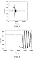
- FIG. 4 is a graph showing an example of time-series data of force.
- FIG. 5 is a graph showing by enlarging a waveform before and after breakage of the test piece TP in the graph of FIG. 4 .
- the vertical axis represents force (kN: kilonewton); the horizontal axis represents time ( ⁇ s: microsecond).
- time-series data of the force obtained by carrying out the test whether or not there is a sufficient number of data points for the later-described spectrum analysis can be confirmed using expression (1).
- a starting point of the data after breakage can be set to, for example, time T 1 at which one and half periods of the vibration waveform have elapsed, as shown in FIG. 5 .
- the test piece TP is replaced (step S12), the settings of the data acquisition conditions are changed (step S13) and the test is carried out again (step S14).
- FIG. 6 is a flowchart showing a natural frequency analysis procedure.
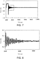
- FIG. 7 is a graph showing an example of time-series data of force.
- FIG. 8 is a graph showing time-series data after breakage of the test piece TP.
- the vertical axis represents force (kN: kilonewton); the horizontal axis represents time ( ⁇ s: microsecond).
- the time-series data of the force acquired in accordance with the measurement procedure shown in FIG. 3 is read from the memory device 57, and the time-series data is separated before and after the force is removed from the test piece TP (step S21).
- the graph shown in FIG. 7 is the force data acquired by carrying out the tensile impact test under the condition of a test speed of 5 m/s at a sampling frequency of 1000 kHz.
- the time-series data is separated into before breakage of the test piece TP and after breakage of the test piece TP.
- time T 1 is determined as explained with reference to FIG.
- step S22 data extraction step
- FFT fast Fourier transform
- FIG. 9 is a graph showing a frequency spectrum analysis result of the time-series data shown in FIG. 8 .
- the horizontal axis represents frequency (Hz: hertz); the vertical axis represents power per frequency resolution ⁇ f.
- the frequency spectrum analysis result is displayed on the display device 58 and stored in the memory device 57.
- the frequency 13.8 kHz having the largest peak is set as the natural frequency (step S24).
- the natural frequency of the impact tester can be obtained simply and accurately without adding a special machine for measuring the natural frequency of the impact tester.
- the user can confirm the effect of natural vibration of the impact tester on the force data during a test execution time slot in each individual impact test.
- the disclosure is also applicable to a punching test in which a punch is caused to collide with a test piece or an impact test such as a three-point bending test in which a punch is struck on a test piece supported by a fulcrum.
Landscapes
- Physics & Mathematics (AREA)
- General Physics & Mathematics (AREA)
- Pathology (AREA)
- Life Sciences & Earth Sciences (AREA)
- Chemical & Material Sciences (AREA)
- Analytical Chemistry (AREA)
- Biochemistry (AREA)
- Health & Medical Sciences (AREA)
- General Health & Medical Sciences (AREA)
- Immunology (AREA)
- Engineering & Computer Science (AREA)
- Signal Processing (AREA)
- Acoustics & Sound (AREA)
- Mathematical Physics (AREA)
- Spectroscopy & Molecular Physics (AREA)
- Manufacturing & Machinery (AREA)
- Investigating Strength Of Materials By Application Of Mechanical Stress (AREA)
Abstract
Description
- The disclosure relates to an evaluation method of an impact test in which force at the time when an impact is rapidly applied to a test piece is detected by a force detector, and to an impact tester.
- For an impact test for evaluating dynamic strength of a material, a tensile impact test (JIS K 7160 "Plastics - Determination of Tensile-Impact Strength") measuring energy at the time when a test piece is broken by a tensile impact at a specified speed, or a puncture impact test (JIS K 7211-2 "Plastics - Determination of Puncture Impact Behavior of Rigid Plastics") causing a striker to vertically collide with a surface of a test piece to obtain an impact force-displacement diagram, or the like, may be used. When the tensile impact test is carried out by an impact tester, both ends of the test piece are gripped by upper and lower grippers, the upper gripper is driven by a hydraulic cylinder at high speed to stretch the test piece, and impact force at breakage of the test piece is detected by a load cell (see Japanese Laid-open No.
2004-333221 2004-333143 - As mentioned above, in a test in which a test jig such as the upper gripper and the punch or the like is moved by the hydraulic cylinder at high speed to apply an impact to the test piece, vibration that occurs when the test piece breaks or vibration that occurs when the punch collides with the test piece may extend over the entire impact tester. In addition, in the impact test, there are cases here and there where noise caused by natural vibration of the impact tester is added to a force waveform.
- In order to know an accurate force value, it is important to know a natural frequency of the impact tester. As a method of obtaining the natural frequency of such an impact tester, the following method, for example, may be considered. The test jig is connected to a force detector, vibration waveform data generated by striking the test jig by a hammer or the like is acquired, and a frequency spectrum analysis is carried out on the waveform. However, in the case of adopting such a method, it is necessary to prepare a striking object such as the hammer or the like, and to add to the impact tester an acceleration sensor, an oscilloscope, a data logger and so on that are for collecting the vibration waveform data, apart from collecting data of a normal test performed by operating the impact tester. In addition, at the time of addition of such machines, in order to obtain accurate vibration waveform data, a user is required to correctly connect and operate the machines and a problem arises that the preparation is messy and takes time.
- The disclosure provides an evaluation method of an impact test and an impact tester, capable of simply and accurately obtaining a natural frequency of the impact tester without adding a special machine for measuring the natural frequency of the impact tester.
- According to a first aspect of the disclosure, an evaluation method of an impact test in which an impact is rapidly applied to a test piece is provided. The evaluation method of the impact test includes: a data extraction step in which a data section for obtaining a natural frequency of an impact tester is extracted from time-series data detected by a force detector by carrying out the impact test, in the data extraction step, the time-series data is separated before and after force is removed from the test piece, and data after the force is removed from the test piece is used as the data section for obtaining the natural frequency of the impact tester; and an analysis step in which a frequency spectrum analysis is carried out on the data section extracted in the data extraction step.
- According to a second aspect of the disclosure, an impact tester rapidly applying an impact to a test piece is provided. The impact tester includes: a load structure, applying force to the test piece; a force detector, detecting the force applied to the test piece; and a control device, including a memory section storing time-series data detected by the force detector, wherein the control device includes: a data extraction section, extracting from the time-series data stored in the memory section a data section for obtaining a natural frequency of the impact tester; and an analysis section, carrying out a frequency spectrum analysis on the data section extracted in the data extraction section.
- According to the first to second aspects of the disclosure, it is possible to know the natural frequency of the impact tester from the force data detected by the force detector when the impact test is carried out. In this way, in the disclosure, since there is no need to add a special machine for measuring the natural frequency of the impact tester, a complicated operation of connecting the additional machine may be omitted, and the impact tester will not become expensive because of the additional machine.
-
-
FIG. 1 is a schematic diagram of an impact tester according to the disclosure. -
FIG. 2 is a block diagram explaining a main control system of the impact tester according to the disclosure. -
FIG. 3 is a flowchart showing a natural vibration measurement procedure. -
FIG. 4 is a graph showing an example of time-series data of force. -
FIG. 5 is a graph showing by enlarging a waveform before and after breakage of a test piece TP in the graph ofFIG. 4 . -
FIG. 6 is a flowchart showing a natural frequency analysis procedure. -
FIG. 7 is a graph showing an example of time-series data of force. -
FIG. 8 is a graph showing time-series data after breakage of the test piece TP. -
FIG. 9 is a graph showing a frequency spectrum analysis result of the time-series data shown inFIG. 8 . - Embodiments of the disclosure are explained based on the drawings.
FIG. 1 is a schematic diagram of an impact tester according to the disclosure.FIG. 2 is a block diagram explaining a main control system of the impact tester according to the disclosure. - The impact tester carries out an impact test rapidly applying an impact to a test piece TP, and includes a
tester body 10 and acontrol device 40. Thetester body 10 includes a table 11, a pair ofsupport posts 12 erected on the table 11, across yoke 13 bridged over the pair ofsupport posts 12, and ahydraulic cylinder 31 fixed to thecross yoke 13. - The
hydraulic cylinder 31 is operated by operating oil supplied via aservo valve 34 from a hydraulic source (not illustrated) disposed in the table 11. Anupper gripper 21 is connected to apiston rod 32 of thehydraulic cylinder 31 via anapproach jig 25 and ajoint 26. Meanwhile, alower gripper 22 is connected to the table 11 via aload cell 27 being a force detector. In this way, the configuration of thetester body 10 is a configuration for carrying out a tensile impact test in which, by providing an approach section in a tensile direction by theapproach jig 25 and pulling up thepiston rod 32 at a high speed of 0.1 m/s to 20 m/s, a pair of grippers that grip both ends of the test piece TP are rapidly separated. A displacement (stroke) of a load structure, i.e., a movement amount of thepiston rod 32, at the time when the tensile impact test is carried out is detected by astroke sensor 33, and force at that time is detected by theload cell 27. - The
control device 40 includes abody control device 41 for controlling operation of thetester body 10, and apersonal computer 42. Thebody control device 41 includes amemory 43 storing programs, anarithmetic device 45 such as a micro processing unit (MPU) or the like performing various operations, and acommunication section 46 communicating with thepersonal computer 42. Thememory 43, thearithmetic device 45 and thecommunication section 46 are connected to one another by abus 61. In addition, thebody control device 41 includes atest control section 44 as a functional configuration. Thetest control section 44 is stored as a test control program in thememory 43. When the tensile impact test is carried out, by executing the test control program, a control signal is provided to theservo valve 34 and thehydraulic cylinder 31 operates. An output signal of thestroke sensor 33 and an output signal of theload cell 27 are taken into thebody control device 41 at predetermined time intervals. - The
personal computer 42 includes amemory 51 consisting of a read-only memory (ROM) that stores a data analysis program, a random access memory (RAM) that loads a program and temporarily stores data when executing the program and so on, anarithmetic device 55 such as a central processing unit (CPU) or the like performing various operations, acommunication section 56 communicating with an external connection machine such as thebody control device 41 or the like, amemory device 57 storing data, adisplay device 58 and aninput device 59. Moreover, thememory device 57 is a memory section storing time-series data of force of an impact test and so on, and is composed of a large capacity memory device such as a hard disk drive (HDD) or the like. Thememory 51, thearithmetic device 55, thecommunication section 56, thememory device 57, thedisplay device 58 and theinput device 59 are connected to one another by a bus 71. - In addition, the
personal computer 42 includes, as a functional configuration, adata extraction section 52 extracting from the time-series data of the force a data section for obtaining a natural frequency of the impact tester in a later-described natural vibration analysis, and ananalysis section 53 carrying out a frequency spectrum analysis on the extracted data section. Thedata extraction section 52 and theanalysis section 53 are respectively stored as a data extraction program and an analysis program in thememory 51. These programs are executed due to the action of thearithmetic device 55. - The force detected by the
load cell 27 when the tensile impact test is carried out is input to thememory 43 of thebody control device 41, and then sent from thecommunication section 46 to thepersonal computer 42. The force received by thecommunication section 56 of thepersonal computer 42 is stored as time-series data in thememory device 57. -
FIG. 3 is a flowchart showing a natural vibration measurement procedure. This flowchart shows the measurement procedure of the natural vibration in a tensile impact test using a synthetic resin piece such as polypropylene (PP), polycarbonate (PC), polystyrene (PS) or the like as the test piece TP. - In a state in which the
upper gripper 21 and thelower gripper 22 being jigs for tensile impact testing are attached to thetester body 10, and it is confirmed that thelower gripper 22 is fixed to theload cell 27 without looseness, first of all, test conditions are set (step S11). A user sets the test conditions such as test speed and so on using theinput device 59 of thepersonal computer 42. Then, both ends of the test piece TP are gripped by theupper gripper 21 and the lower gripper 22 (step S12). - Next, data acquisition conditions are set (step S13). The user sets data collection conditions, such as data collection start time and data collection end time, sampling frequency, number of acquired data points (number of sampling points) and so on, using the
input device 59 of thepersonal computer 42. The natural vibration that occurs in thetester body 10 during testing can be acquired by observing vibrations that become noticeable when a load applied to theload cell 27 via the test piece TP is removed due to breakage. In addition, in a state in which no test load is applied, the force in a state of receiving weight of a test jig (in this embodiment, the lower gripper 22) also needs to be known. Accordingly, in setting of the data collection start time and the data collection end time, it is preferable to set so that the data can be acquired before a tensile load is applied to the test piece TP and that a sufficient number of data points (e.g., a number of data points in which the number of data points after breakage of the test piece TP becomes 1000 points or more) for the later-described spectrum analysis can be obtained. In setting of the sampling frequency and the number of sampling points, it is preferable to use the following expression (1) to set values at which frequency resolution becomes 500 Hz or less.
- Moreover, in expression (1), Δf represents the frequency resolution, T represents a time window length, Fs represents the sampling frequency and N represents the number of sampling points.
- When the setting of the data acquisition conditions is ended, a test is carried out (step S14). The force detected by the
load cell 27 during a period from the data collection start time to the data collection end time set in the data acquisition conditions is sent to thepersonal computer 42 via thebody control device 41 and saved in thememory device 57, and the measurement is ended (step S15). -
FIG. 4 is a graph showing an example of time-series data of force.FIG. 5 is a graph showing by enlarging a waveform before and after breakage of the test piece TP in the graph ofFIG. 4 . In these graphs, the vertical axis represents force (kN: kilonewton); the horizontal axis represents time (µs: microsecond). - With respect to the time-series data of the force obtained by carrying out the test, whether or not there is a sufficient number of data points for the later-described spectrum analysis can be confirmed using expression (1). In the time-series data of the force as shown in the graph of
FIG. 4 , as shown by enlargement inFIG. 5 , an amplitude of a force waveform at around 15000 µs increases due to the breakage. A starting point of the data after breakage can be set to, for example, time T1 at which one and half periods of the vibration waveform have elapsed, as shown inFIG. 5 . Moreover, when a sufficient number of data points for the later-described spectrum analysis cannot be acquired, the test piece TP is replaced (step S12), the settings of the data acquisition conditions are changed (step S13) and the test is carried out again (step S14). -
FIG. 6 is a flowchart showing a natural frequency analysis procedure.FIG. 7 is a graph showing an example of time-series data of force.FIG. 8 is a graph showing time-series data after breakage of the test piece TP. In the graphs ofFIG. 7 and FIG. 8 , the vertical axis represents force (kN: kilonewton); the horizontal axis represents time (µs: microsecond). - In the natural vibration analysis, first of all, the time-series data of the force acquired in accordance with the measurement procedure shown in
FIG. 3 is read from thememory device 57, and the time-series data is separated before and after the force is removed from the test piece TP (step S21). The graph shown inFIG. 7 is the force data acquired by carrying out the tensile impact test under the condition of a test speed of 5 m/s at a sampling frequency of 1000 kHz. In the tensile impact test, the time-series data is separated into before breakage of the test piece TP and after breakage of the test piece TP. In separation of the time-series data of the force, time T1 is determined as explained with reference toFIG. 5 , and the data is separated before and after time T1. Then, as shown in broken lines inFIG. 7 , the data at and after time T1 (2440 µs) is extracted as the data section for obtaining the natural frequency of the impact tester (step S22: data extraction step). Thereafter, a frequency spectrum analysis by fast Fourier transform (FFT) is carried out on the time-series data after breakage of the test piece TP that is extracted in step S22 and is shown inFIG. 8 (step S23: analysis step). -
FIG. 9 is a graph showing a frequency spectrum analysis result of the time-series data shown inFIG. 8 . In this graph, the horizontal axis represents frequency (Hz: hertz); the vertical axis represents power per frequency resolution Δf. - The frequency spectrum analysis result is displayed on the
display device 58 and stored in thememory device 57. In the power spectrum shown inFIG. 9 , the frequency 13.8 kHz having the largest peak is set as the natural frequency (step S24). - In this way, in the disclosure, since a natural frequency can be obtained by using force data at the time when a test is carried out, the natural frequency of the impact tester can be obtained simply and accurately without adding a special machine for measuring the natural frequency of the impact tester. In addition, in the disclosure, the user can confirm the effect of natural vibration of the impact tester on the force data during a test execution time slot in each individual impact test.
- Moreover, although the explanation is made with respect to the tensile impact test in the above-mentioned embodiments, the disclosure is also applicable to a punching test in which a punch is caused to collide with a test piece or an impact test such as a three-point bending test in which a punch is struck on a test piece supported by a fulcrum.
-
- 10: tester body;
- 11: table;
- 12: support post;
- 13: cross yoke;
- 21: upper gripper;
- 22: lower gripper;
- 25: approach jig;
- 26: joint;
- 27: load cell;
- 31: hydraulic cylinder;
- 32: piston rod;
- 33: stroke sensor;
- 34: servo valve;
- 40: control device;
- 41: body control device;
- 42: personal computer;
- 43: memory;
- 44: test control section;
- 45: arithmetic device;
- 46: communication section;
- 51: memory;
- 52: data extraction section;
- 53: analysis section;
- 55: arithmetic device;
- 56: communication section;
- 57: memory device;
- 58: display device;
- 59: input device;
- TP: test piece.
Claims (2)
- An evaluation method of an impact test in which an impact is rapidly applied to a test piece (TP), characterized by comprising:a data extraction step (S22) in which a data section for obtaining a natural frequency of an impact tester is extracted from time-series data detected by a force detector by carrying out the impact test, wherein in the data extraction step (S22), the time-series data is separated before and after force is removed from the test piece (TP), and data after the force is removed from the test piece (TP) is used as the data section for obtaining the natural frequency of the impact tester; andan analysis step (S23) in which a frequency spectrum analysis is carried out on the data section extracted in the data extraction step (S22).
- An impact tester rapidly applying an impact to a test piece (TP), characterized by comprising:a load structure, applying force to the test piece (TP);a force detector, detecting the force applied to the test piece (TP); anda control device (40), comprising a memory section storing time-series data detected by the force detector,wherein the control device (40) comprises:a data extraction section (52), extracting from the time-series data stored in the memory section a data section for obtaining a natural frequency of the impact tester; andan analysis section (53), carrying out a frequency spectrum analysis on the data section extracted in the data extraction section (52)
Applications Claiming Priority (1)
| Application Number | Priority Date | Filing Date | Title |
|---|---|---|---|
| JP2017118516A JP6794936B2 (en) | 2017-06-16 | 2017-06-16 | Impact test evaluation method and impact tester |
Publications (1)
| Publication Number | Publication Date |
|---|---|
| EP3415893A1 true EP3415893A1 (en) | 2018-12-19 |
Family
ID=62636119
Family Applications (1)
| Application Number | Title | Priority Date | Filing Date |
|---|---|---|---|
| EP18177789.7A Withdrawn EP3415893A1 (en) | 2017-06-16 | 2018-06-14 | Evaluation method of impact test and impact tester |
Country Status (4)
| Country | Link |
|---|---|
| US (1) | US20180364140A1 (en) |
| EP (1) | EP3415893A1 (en) |
| JP (1) | JP6794936B2 (en) |
| CN (1) | CN109142101A (en) |
Cited By (2)
| Publication number | Priority date | Publication date | Assignee | Title |
|---|---|---|---|---|
| EP3415894A1 (en) * | 2017-06-16 | 2018-12-19 | Shimadzu Corporation | Evaluation method of impact test and impact tester |
| CN113343388A (en) * | 2021-06-22 | 2021-09-03 | 安徽容知日新科技股份有限公司 | Method for acquiring steady-state vibration data and computing equipment |
Families Citing this family (5)
| Publication number | Priority date | Publication date | Assignee | Title |
|---|---|---|---|---|
| JP7135932B2 (en) * | 2019-02-26 | 2022-09-13 | 株式会社島津製作所 | TENSILE TESTER AND CONTROL METHOD FOR TENSILE TESTER |
| EP3754331A1 (en) * | 2019-06-20 | 2020-12-23 | GrindoSonic BVBA | Method and system for analysing a test piece using a vibrational response signal |
| CN114667442A (en) * | 2019-10-04 | 2022-06-24 | 明普拉西斯解决方案有限公司 | Rock Hardness Measurement |
| CN112098254B (en) * | 2020-09-27 | 2023-04-07 | 河南工业职业技术学院 | Control system for impact test |
| DE102022115919A1 (en) * | 2022-06-27 | 2023-12-28 | 4A Engineering Gmbh | Material testing device for material testing of a sample |
Citations (9)
| Publication number | Priority date | Publication date | Assignee | Title |
|---|---|---|---|---|
| GB118175A (en) * | 1917-09-22 | 1918-08-22 | Avery Ltd W & T | Improvements in Impact Testing Machines. |
| JPH08105868A (en) * | 1994-10-06 | 1996-04-23 | Iwatsu Electric Co Ltd | Material constant measuring method and device |
| EP1070961A1 (en) * | 1999-07-19 | 2001-01-24 | BRITISH TELECOMMUNICATIONS public limited company | Test apparatus |
| JP2004333143A (en) | 2003-04-30 | 2004-11-25 | Shimadzu Corp | Impact testing machine and its installation structure |
| JP2004333221A (en) | 2003-05-02 | 2004-11-25 | Shimadzu Corp | Spanner for impact tensile tester, mounting method of test piece of impact tensile tester and impact tensile tester |
| EP2120034A1 (en) * | 2008-05-16 | 2009-11-18 | Vrije Universiteit Brussel | Method and apparatus for providing an optimal test panel for the non-destructive measurement of elastic properties of structural materials |
| WO2012004969A1 (en) * | 2010-07-06 | 2012-01-12 | 信越化学工業株式会社 | Polycrystalline silicon rod, method for inspecting polycrystalline silicon rod, and method for manufacturing polycrystalline silicon rod |
| WO2012153956A2 (en) * | 2011-05-09 | 2012-11-15 | Industry-Academia Cooperation Group Of Sejong University | Impact test apparatus using energy frame |
| US20160084802A1 (en) * | 2014-09-19 | 2016-03-24 | King Fahd University Of Petroleum And Minerals | Process for determining weld quality using flexural characteristics |
Family Cites Families (5)
| Publication number | Priority date | Publication date | Assignee | Title |
|---|---|---|---|---|
| DE10214756B4 (en) * | 2002-04-03 | 2011-06-16 | Mettler-Toledo Ag | Method and device for carrying out dynamic-mechanical analyzes |
| JP4033119B2 (en) * | 2003-12-10 | 2008-01-16 | 株式会社島津製作所 | Material testing method, material testing machine |
| CN2842407Y (en) * | 2005-09-27 | 2006-11-29 | 中国矿业大学 | Impaction and friction wear testing machine |
| JP5527696B2 (en) * | 2010-09-27 | 2014-06-18 | 地方独立行政法人大阪府立産業技術総合研究所 | Impact strength evaluation apparatus, method and program |
| CN104483216A (en) * | 2014-12-31 | 2015-04-01 | 华侨大学 | Ultrasonic-vibration based microscale testing device for material impact fatigue |
-
2017
- 2017-06-16 JP JP2017118516A patent/JP6794936B2/en not_active Expired - Fee Related
-
2018
- 2018-06-14 EP EP18177789.7A patent/EP3415893A1/en not_active Withdrawn
- 2018-06-15 US US16/009,219 patent/US20180364140A1/en not_active Abandoned
- 2018-06-15 CN CN201810617935.2A patent/CN109142101A/en not_active Withdrawn
Patent Citations (9)
| Publication number | Priority date | Publication date | Assignee | Title |
|---|---|---|---|---|
| GB118175A (en) * | 1917-09-22 | 1918-08-22 | Avery Ltd W & T | Improvements in Impact Testing Machines. |
| JPH08105868A (en) * | 1994-10-06 | 1996-04-23 | Iwatsu Electric Co Ltd | Material constant measuring method and device |
| EP1070961A1 (en) * | 1999-07-19 | 2001-01-24 | BRITISH TELECOMMUNICATIONS public limited company | Test apparatus |
| JP2004333143A (en) | 2003-04-30 | 2004-11-25 | Shimadzu Corp | Impact testing machine and its installation structure |
| JP2004333221A (en) | 2003-05-02 | 2004-11-25 | Shimadzu Corp | Spanner for impact tensile tester, mounting method of test piece of impact tensile tester and impact tensile tester |
| EP2120034A1 (en) * | 2008-05-16 | 2009-11-18 | Vrije Universiteit Brussel | Method and apparatus for providing an optimal test panel for the non-destructive measurement of elastic properties of structural materials |
| WO2012004969A1 (en) * | 2010-07-06 | 2012-01-12 | 信越化学工業株式会社 | Polycrystalline silicon rod, method for inspecting polycrystalline silicon rod, and method for manufacturing polycrystalline silicon rod |
| WO2012153956A2 (en) * | 2011-05-09 | 2012-11-15 | Industry-Academia Cooperation Group Of Sejong University | Impact test apparatus using energy frame |
| US20160084802A1 (en) * | 2014-09-19 | 2016-03-24 | King Fahd University Of Petroleum And Minerals | Process for determining weld quality using flexural characteristics |
Cited By (3)
| Publication number | Priority date | Publication date | Assignee | Title |
|---|---|---|---|---|
| EP3415894A1 (en) * | 2017-06-16 | 2018-12-19 | Shimadzu Corporation | Evaluation method of impact test and impact tester |
| CN113343388A (en) * | 2021-06-22 | 2021-09-03 | 安徽容知日新科技股份有限公司 | Method for acquiring steady-state vibration data and computing equipment |
| CN113343388B (en) * | 2021-06-22 | 2022-07-08 | 安徽容知日新科技股份有限公司 | Method for acquiring steady-state vibration data and computing equipment |
Also Published As
| Publication number | Publication date |
|---|---|
| JP2019002827A (en) | 2019-01-10 |
| JP6794936B2 (en) | 2020-12-02 |
| CN109142101A (en) | 2019-01-04 |
| US20180364140A1 (en) | 2018-12-20 |
Similar Documents
| Publication | Publication Date | Title |
|---|---|---|
| US20180364140A1 (en) | Evaluation method of impact test and impact tester | |
| EP3521799B1 (en) | Test result evaluating method and material tester | |
| EP3415894A1 (en) | Evaluation method of impact test and impact tester | |
| EP3521801B1 (en) | Test result evaluating method and a kit comprising a material tester and a hammer | |
| US6804994B2 (en) | Dynamic loading system, dynamic loading method and dynamic loading test method for piles | |
| EP2444787A1 (en) | Method and device for bridge state evaluation using dynamic method | |
| US6422079B1 (en) | Ground anchorage testing apparatus | |
| JP2019056614A (en) | Noise removal method for material testing and material testing machine | |
| JP2019002828A5 (en) | ||
| CN104913988B (en) | Concrete axial tensile strength measuring method based on Hopkinson principle | |
| KR20210125665A (en) | Fatigue Test System of Materials Using Vibration Tester | |
| EP3141305A1 (en) | Experimental method to detect the elastic modulus of objects, samples or semi-worked products of various materials | |
| Lorriot | Specimen loading determined by displacement measurement in instrumented Charpy impact test | |
| Söver et al. | High impact-testing machine for elastomers investigation under impact loads | |
| CN117571457A (en) | High-speed tensile testing fixture, high-speed tensile testing device and method | |
| CN221528173U (en) | Impact test device for testing mechanical properties of metal | |
| CN104180985A (en) | Heald raising knife frequency spectrum curve measurement method and device | |
| RU2402767C2 (en) | Method to test asphalt-concrete mixtures for caking | |
| JP2021009072A (en) | Ground anchor tension evaluation method and tension evaluation system | |
| Tcherniak et al. | On the feasibility of utilizing vibrations for bolted joint assessment | |
| Yoo et al. | Application of Model-based Design Approach on Dynamic Tensile Testing of Carbon/Epoxy Composites at Intermediate Strain Rates | |
| JP2017032479A (en) | Member state evaluation apparatus and state evaluation method | |
| NEDELCU et al. | The estimation of dynamic properties of a fixed beam using experimental modal testing | |
| Jayashankar et al. | Output only modal analysis of engineering structures | |
| JP2006322734A (en) | Nondestructive inspection method for existing piles |
Legal Events
| Date | Code | Title | Description |
|---|---|---|---|
| PUAI | Public reference made under article 153(3) epc to a published international application that has entered the european phase |
Free format text: ORIGINAL CODE: 0009012 |
|
| STAA | Information on the status of an ep patent application or granted ep patent |
Free format text: STATUS: REQUEST FOR EXAMINATION WAS MADE |
|
| 17P | Request for examination filed |
Effective date: 20180614 |
|
| AK | Designated contracting states |
Kind code of ref document: A1 Designated state(s): AL AT BE BG CH CY CZ DE DK EE ES FI FR GB GR HR HU IE IS IT LI LT LU LV MC MK MT NL NO PL PT RO RS SE SI SK SM TR |
|
| AX | Request for extension of the european patent |
Extension state: BA ME |
|
| STAA | Information on the status of an ep patent application or granted ep patent |
Free format text: STATUS: EXAMINATION IS IN PROGRESS |
|
| 17Q | First examination report despatched |
Effective date: 20191219 |
|
| GRAP | Despatch of communication of intention to grant a patent |
Free format text: ORIGINAL CODE: EPIDOSNIGR1 |
|
| STAA | Information on the status of an ep patent application or granted ep patent |
Free format text: STATUS: GRANT OF PATENT IS INTENDED |
|
| INTG | Intention to grant announced |
Effective date: 20210422 |
|
| STAA | Information on the status of an ep patent application or granted ep patent |
Free format text: STATUS: THE APPLICATION IS DEEMED TO BE WITHDRAWN |
|
| 18D | Application deemed to be withdrawn |
Effective date: 20210903 |