EP3415844A1 - Refrigerating unit for transportation - Google Patents
Refrigerating unit for transportation Download PDFInfo
- Publication number
- EP3415844A1 EP3415844A1 EP17815282.3A EP17815282A EP3415844A1 EP 3415844 A1 EP3415844 A1 EP 3415844A1 EP 17815282 A EP17815282 A EP 17815282A EP 3415844 A1 EP3415844 A1 EP 3415844A1
- Authority
- EP
- European Patent Office
- Prior art keywords
- air guide
- control box
- air
- radiating fin
- heat radiating
- Prior art date
- Legal status (The legal status is an assumption and is not a legal conclusion. Google has not performed a legal analysis and makes no representation as to the accuracy of the status listed.)
- Granted
Links
Images


Classifications
-
- F—MECHANICAL ENGINEERING; LIGHTING; HEATING; WEAPONS; BLASTING
- F25—REFRIGERATION OR COOLING; COMBINED HEATING AND REFRIGERATION SYSTEMS; HEAT PUMP SYSTEMS; MANUFACTURE OR STORAGE OF ICE; LIQUEFACTION SOLIDIFICATION OF GASES
- F25B—REFRIGERATION MACHINES, PLANTS OR SYSTEMS; COMBINED HEATING AND REFRIGERATION SYSTEMS; HEAT PUMP SYSTEMS
- F25B31/00—Compressor arrangements
- F25B31/006—Cooling of compressor or motor
-
- F—MECHANICAL ENGINEERING; LIGHTING; HEATING; WEAPONS; BLASTING
- F25—REFRIGERATION OR COOLING; COMBINED HEATING AND REFRIGERATION SYSTEMS; HEAT PUMP SYSTEMS; MANUFACTURE OR STORAGE OF ICE; LIQUEFACTION SOLIDIFICATION OF GASES
- F25D—REFRIGERATORS; COLD ROOMS; ICE-BOXES; COOLING OR FREEZING APPARATUS NOT OTHERWISE PROVIDED FOR
- F25D11/00—Self-contained movable devices, e.g. domestic refrigerators
-
- B—PERFORMING OPERATIONS; TRANSPORTING
- B60—VEHICLES IN GENERAL
- B60H—ARRANGEMENTS OF HEATING, COOLING, VENTILATING OR OTHER AIR-TREATING DEVICES SPECIALLY ADAPTED FOR PASSENGER OR GOODS SPACES OF VEHICLES
- B60H1/00—Heating, cooling or ventilating devices
- B60H1/00271—HVAC devices specially adapted for particular vehicle parts or components and being connected to the vehicle HVAC unit
-
- B—PERFORMING OPERATIONS; TRANSPORTING
- B60—VEHICLES IN GENERAL
- B60H—ARRANGEMENTS OF HEATING, COOLING, VENTILATING OR OTHER AIR-TREATING DEVICES SPECIALLY ADAPTED FOR PASSENGER OR GOODS SPACES OF VEHICLES
- B60H1/00—Heating, cooling or ventilating devices
- B60H1/32—Cooling devices
- B60H1/3204—Cooling devices using compression
- B60H1/3227—Cooling devices using compression characterised by the arrangement or the type of heat exchanger, e.g. condenser, evaporator
-
- B—PERFORMING OPERATIONS; TRANSPORTING
- B60—VEHICLES IN GENERAL
- B60H—ARRANGEMENTS OF HEATING, COOLING, VENTILATING OR OTHER AIR-TREATING DEVICES SPECIALLY ADAPTED FOR PASSENGER OR GOODS SPACES OF VEHICLES
- B60H1/00—Heating, cooling or ventilating devices
- B60H1/32—Cooling devices
- B60H1/3204—Cooling devices using compression
- B60H1/3232—Cooling devices using compression particularly adapted for load transporting vehicles
-
- F—MECHANICAL ENGINEERING; LIGHTING; HEATING; WEAPONS; BLASTING
- F25—REFRIGERATION OR COOLING; COMBINED HEATING AND REFRIGERATION SYSTEMS; HEAT PUMP SYSTEMS; MANUFACTURE OR STORAGE OF ICE; LIQUEFACTION SOLIDIFICATION OF GASES
- F25D—REFRIGERATORS; COLD ROOMS; ICE-BOXES; COOLING OR FREEZING APPARATUS NOT OTHERWISE PROVIDED FOR
- F25D11/00—Self-contained movable devices, e.g. domestic refrigerators
- F25D11/003—Transport containers
-
- F—MECHANICAL ENGINEERING; LIGHTING; HEATING; WEAPONS; BLASTING
- F25—REFRIGERATION OR COOLING; COMBINED HEATING AND REFRIGERATION SYSTEMS; HEAT PUMP SYSTEMS; MANUFACTURE OR STORAGE OF ICE; LIQUEFACTION SOLIDIFICATION OF GASES
- F25D—REFRIGERATORS; COLD ROOMS; ICE-BOXES; COOLING OR FREEZING APPARATUS NOT OTHERWISE PROVIDED FOR
- F25D19/00—Arrangement or mounting of refrigeration units with respect to devices or objects to be refrigerated, e.g. infrared detectors
-
- F—MECHANICAL ENGINEERING; LIGHTING; HEATING; WEAPONS; BLASTING
- F25—REFRIGERATION OR COOLING; COMBINED HEATING AND REFRIGERATION SYSTEMS; HEAT PUMP SYSTEMS; MANUFACTURE OR STORAGE OF ICE; LIQUEFACTION SOLIDIFICATION OF GASES
- F25D—REFRIGERATORS; COLD ROOMS; ICE-BOXES; COOLING OR FREEZING APPARATUS NOT OTHERWISE PROVIDED FOR
- F25D23/00—General constructional features
- F25D23/003—General constructional features for cooling refrigerating machinery
-
- H—ELECTRICITY
- H05—ELECTRIC TECHNIQUES NOT OTHERWISE PROVIDED FOR
- H05K—PRINTED CIRCUITS; CASINGS OR CONSTRUCTIONAL DETAILS OF ELECTRIC APPARATUS; MANUFACTURE OF ASSEMBLAGES OF ELECTRICAL COMPONENTS
- H05K7/00—Constructional details common to different types of electric apparatus
- H05K7/20—Modifications to facilitate cooling, ventilating, or heating
-
- H—ELECTRICITY
- H10—SEMICONDUCTOR DEVICES; ELECTRIC SOLID-STATE DEVICES NOT OTHERWISE PROVIDED FOR
- H10W—GENERIC PACKAGES, INTERCONNECTIONS, CONNECTORS OR OTHER CONSTRUCTIONAL DETAILS OF DEVICES COVERED BY CLASS H10
- H10W40/00—Arrangements for thermal protection or thermal control
- H10W40/40—Arrangements for thermal protection or thermal control involving heat exchange by flowing fluids
- H10W40/43—Arrangements for thermal protection or thermal control involving heat exchange by flowing fluids by flowing gases, e.g. forced air cooling
-
- B—PERFORMING OPERATIONS; TRANSPORTING
- B60—VEHICLES IN GENERAL
- B60H—ARRANGEMENTS OF HEATING, COOLING, VENTILATING OR OTHER AIR-TREATING DEVICES SPECIALLY ADAPTED FOR PASSENGER OR GOODS SPACES OF VEHICLES
- B60H1/00—Heating, cooling or ventilating devices
- B60H1/00271—HVAC devices specially adapted for particular vehicle parts or components and being connected to the vehicle HVAC unit
- B60H2001/003—Component temperature regulation using an air flow
Definitions
- the present invention relates to a refrigerating unit for transportation mounted on a vehicle.
- a power generated by a generator using a drive force of a traveling engine or power from a commercial power supply drives a compressor or the like.
- the refrigerating unit for transportation includes a control box which houses a control device (for example, an inverter or an AC/DC converter) controlling a refrigerating device such as the generator or the compressor, and in this case, a heat radiating fin for cooling the control device (the inverter, the AC/DC converter, or the like) which is a heating part is integrally provided in the control box.
- a control device for example, an inverter or an AC/DC converter
- PTL 1 discloses a refrigerating unit for transportation which guides exhaust air of a condenser fan to a heat radiating fin integrally formed in an electrical component storage box and cools an inverter or an AC / DC converter housed in the electrical component storage box.
- the present invention is made in consideration of the above-described circumstances, and an object thereof is to provide a refrigerating unit for transportation capable of reducing a size of the heat radiating fin cooling the control device housed in the control box.
- a refrigerating unit for transportation of the present invention adopts the following means.
- a refrigerating unit for transportation including: a refrigerating device which is attached to a front surface of a van body and includes a condenser and a condenser fan which discharges air which has passed through the condenser; a control device which controls the refrigerating device; a control box which includes a heat radiating fin for cooling the control device on an outer surface of the control box and houses the control device; and an air guide passage through which outside air is guided to the heat radiating fin and outside air which has passed through the heat radiating fin is guided to an intake side of the condenser fan.
- the outside air can flow through the heat radiating fin for cooling the control device through the air guide passage, and thus, it is possible to cool the control device by heat exchange between the heat radiating fin and the outside air.
- the outside air having a relatively low temperature flows through the heat radiating fin, and thus, it is possible to cool the control device by a small-sized heat radiating fin.
- the outside air which has passed through the heat radiating fin through the air guide passage is guided to the condenser fan, and thus, the outside air cooling the control device can flow through the heat radiating fin by the condenser fan, and the outside air can flow through the heat radiating fin even in any vehicle traveling state (for example, a vehicle stopped state) so as to cool the control device.
- the condenser fan is used in order to cause the outside air to flow through the heat radiating fin cooling the control device, and thus, it is not necessary to newly provide other fans or the like, and it is possible to decrease the number of parts.
- the air guide passage may include an intake port through which the outside air is introduced and may be positioned behind the condenser fan, the refrigerating device may be attached to the front surface of the van body, the control box may be disposed on an upper surface of the refrigerating device so as to be separated from the front surface of the van body, and the intake port may be open between the control box and the front surface of the van body.
- a high-temperature exhaust air is discharged from a traveling engine.
- the discharged exhaust air flows the rear side of the vehicle by running wind of the vehicle and rises along the front surface of the van body.
- the refrigerating device is attached to the front surface of the van body, the intake port of the air guide passage is provided above the refrigerating device, and thus, the rising exhaust air is blocked by the refrigerating device, and the exhaust air does not reach the intake port. Accordingly, the exhaust air of the traveling engine is not easily mixed with the outside air sucked from the intake port, and thus, when the vehicle travels, the outside air flowing through the air guide passage can be maintained at a low temperature, and it is possible to suitably cool the control box.
- an upper surface of the control box may be lower than an upper surface of the van body.
- the upper surface of the control box is lower than the upper surface of the van body. Accordingly, a portion of wind (for example, running wind) from the front of the vehicle toward the rear of the vehicle passes through a portion above the control box and abuts against an upper portion of the front surface of the van body. If the wind abuts against the upper portion of the front surface of the van body, a pressure around the upper portion increases.
- the intake port is open between the control box and the van body, a pressure difference between the intake port and the discharge port increases, and thus, much outside air can be guided to the air guide passage. Accordingly, much more outside air can flow through the heat radiating fin, much outside air and the heat radiating fin can be heat-exchanged with each other, and thus, it is possible to more suitably cool the control device.
- the air guide passage may include an intake port through which the outside air is sucked and may be positioned in front of the condenser fan, and the intake port may be open forward.
- the air guide passage is positioned in front of the condenser fan and the intake port is open forward. Accordingly, a dynamic pressure of wind (for example, the running wind of the vehicle) from the front of the vehicle toward the rear of the vehicle is used, and thus, the outside air is easily introduced into the intake port, and much outside air can be introduced to the air guide passage to flow through the heat radiating fin. Accordingly, much outside air and the heat radiating fin can be heat-exchanged, and thus, it is possible to suitably cool the control box.
- a dynamic pressure of wind for example, the running wind of the vehicle
- the air guide passage is positioned in the front portion of the vehicle and the intake port is open forward, and thus, the exhaust air of the traveling engine is not easily mixed with the outside air sucked from the intake port. Accordingly, when the vehicle travels, the outside air flowing through the air guide passage can be maintained at a low temperature, and it is possible to suitably cool the control box.
- a recessed portion which is recessed upward along the control device may be formed on a lower surface of the control box, the heat radiating fin may be disposed in the recessed portion, and the recessed portion may constitute a portion of the air guide passage.
- the recessed portion is formed in the control box, and the heat radiating fin is disposed in the recessed portion. Accordingly, a height of the control box can be set regardless of a height of the heat radiating fin. Therefore, it is possible to suppress the height of the control box, and it is possible to suppress a height of the refrigerating unit for transportation.
- the recessed portion is formed on the lower surface of the control box along the control device, and the recessed portion is recessed upward. Accordingly, in a case where outside air flows through the heat radiating fin, the recessed portion of the control box can be a portion of the air guide passage. Therefore, it is not necessary to newly provide a part such as a duct exclusively for the air guide passage, and it is possible to form the air guide passage while decreasing the number of parts.
- a plurality of the condenser fans may be provided, and the air guide passage may communicate with each of the plurality of condenser fans.
- the air guide passage communicates with the plurality of condenser fans. Accordingly, even in a case where one condenser fan is failed, outside air can be guided from the intake port to the air guide passage by the other condenser fan to cool the control device.
- the air guide passage may be formed by an air guide plate, and the air guide plate may extend to the vicinity of the condenser fan.
- the air guide plate forming the air guide passage extends to the vicinity of the condenser fan. Accordingly, it is possible to introduce the outside air to the air guide passage and guide the outside air to the heat radiating fin more reliably so as to cool the control device.
- a vehicle 2 on which a refrigerating unit for transportation 1 according to the present embodiment is mounted is a transportation truck in which a traveling engine (not shown) is disposed below a cab 3.
- the cab 3 is rotatable by a predetermined angle about a shaft (not shown) extending in a vehicle width direction at a lower portion of a front end.
- a van body 4 is mounted on a frame which extends in a front-rear direction behind the cab 3. Loads such as frozen and refrigerated items are loaded in the van body 4.
- the refrigerating unit for transportation 1 is provided on an upper portion of a front surface 4a of the van body 4 so as to protrude to a portion above the cab 3 over an approximately entire region in the vehicle width direction.
- the refrigerating unit for transportation 1 supplies generated cool air into the van body 4 so as to maintain a temperature in the van body 4 to a constant temperature.
- the refrigerating unit for transportation 1 includes a refrigerating device 5 which is fixed to the van body 4, a control box 6 which is installed on an upper surface 5a of the refrigerating device 5, and an air guide portion 8 which forms a portion of an air guide passage 20 described later.
- the refrigerating unit for transportation 1 has an approximately right triangle shape when viewed from a side, and a front surface 1a is inclined so that a length thereof in the front-rear direction decreases from an upper side to a lower side. That is, the shape of the refrigerating unit for transportation 1 1 is made such that the cab 3 and the refrigerating unit for transportation 1 do not interfere with each other when the above-described cab 3 is rotated.
- a plurality of air holes through which air is introduced into the refrigerating unit for transportation 1 are formed on the front surface 1a of the refrigerating unit for transportation 1.
- the refrigerating device 5 is attached to the front surface 4a of the van body 4, and includes two condenser fans 7 which are provided to be arranged right and left in front of an electric compressor (not shown), an evaporator (not shown), and the control box 6, a refrigerating device body portion 11 in which a generator (not shown) generating electricity by a drive force of the traveling engine or the like is accommodated, and a condenser 12 which is positioned in front of the refrigerating device body portion 11 and is disposed along the front surface 1a of the refrigerating unit for transportation 1.
- the electric compressor, the evaporator, or the like disposed inside the refrigerating device body portion 11 and the condenser 12 are connected to each other via a refrigerant pipe (not shown), and constitute a refrigerating cycle.
- the two condenser fans 7 are disposed such that they are arranged in the vehicle width direction above the condenser 12 and in front of the control box 6 (refer to Figs. 2 and 3 ) and are rotated about vertical axes of the vehicle so as to discharge air inside the refrigerating unit for transportation 1 to the outside.
- the control box 6 has an approximately rectangular box shape extending in the vehicle width direction, and is disposed on an upper surface of the refrigerating device body portion 11 such that that a rear surface of the control box 6 and the front surface 4a of the van body 4 are separated from each other.
- a front end of the control box 6 is positioned in front of a front end of the refrigerating device 5.
- An upper surface 6a of the control box 6 is lower than an upper surface 4b of the van body 4.
- a control device (not shown) is housed inside the control box 6, and the control device controls the refrigerating device 5 such as an inverter device and an AC/DC converter (for example, a three-phase full wave rectifier using a diode).
- the control box 6 is formed of an aluminum alloy or the like which is lightweight and has improved heat conductivity. Moreover, as shown in Figs. 4 and 5 , a recessed portion 13 which extends in the front-rear direction and is recessed upward is formed on a lower surface at an approximately center of the control box 6 in the vehicle width direction over the entire region in the front-rear direction. In the recessed portion 13, a heat radiating fin 14 for cooling a heating part such as an inverter device and an AC/DC converter housed in the control box 6 is integrally provided with the control box 6.
- the heat radiating fin 14 is a flat plate shape extending in the vehicular front-rear direction (that is, a direction in which the recessed portion 13 extends) and is formed of an aluminum alloy having improved heat conductivity.
- a raw material of each of the control box 6 and the heat radiating fin 14 is not limited to the aluminum alloy.
- the control box may be formed of a steel plate having iron as a raw material.
- the heat radiating fin 14 (refer to Fig. 4 ) is not shown.
- the air guide portion 8 includes a first air guide plate 15 which extends forward from an upper front surface of the refrigerating device 5, and a second air guide plate 16 which extend forward from an upper surface of the recessed portion 13 of the control box 6.
- the first air guide plate 15 includes a flat plate-shaped lower surface portion 15a, and side surface portions (not show) which are erected upward from both ends of the lower surface portion 15a in the vehicle width direction.
- the second air guide plate 16 includes a first horizontal portion 16a which extends forward from the upper surface of the recessed portion 13, a vertical portion 16b which extend downward from a front end of the first horizontal portion 16a, and a second horizontal portion 16c which extends forward from the vertical portion 16b. Both ends of the first horizontal portion 16a, the vertical portion 16b, and the second horizontal portion 16c in the vehicle width direction are connected to upper ends of the side surface portions. That is, a duct-shaped closed space is formed inside by the first air guide plate 15 and the second air guide plate 16.
- both end portions of the air guide portion 8 in the vehicle width direction are curved or inclined such that the width of the air guide portion 8 in the vehicle width direction increases forward.
- a right front end and a left front end of the air guide portion 8 are respectively installed around the condenser fans 7 provided right and left, and openings are formed on the right front end and the left front end of the air guide portion 8. That is, air guide portion 8 is open to face the entireties in the vehicle width direction of the condenser fans 7 arranged right and left.
- the recessed portion 13 is formed such that the lower surface of the control box 6 installed on the upper surface 5a of the refrigerating device 5 is recessed upward and is formed to extend in the front-rear direction over the entire region of the control box 6 in the front-rear direction.
- the control box 6 is disposed so as to be separated from the van body 4 positioned behind the control box 6. Accordingly, the recessed portion 13 has a duct structure which has openings in a front end portion and a rear end portion thereof and extends in the front-rear direction.
- the above-described air guide portion 8 extends to the vicinities of the condenser fans 7 in a duct shape from the front end portion of the recessed portion 13. Accordingly, the recessed portion 13 and the air guide portion 8 are connected to each other, and thus, the air guide passage 20 is formed in which the recessed portion 13 is set to an upstream portion and the air guide portion 8 is a downstream portion.
- the rear end portion of the recessed portion 13 is set to an intake port 21 through which outside air is introduced into the air guide passage 20 and openings formed on the right front end and the left front end of the air guide portion 8 are set to a discharge port 22 through which the introduced air is discharged.
- the end portion of the first air guide plate 15 on the discharge port 22 side extends to a portion vertically below a wing portion of the condenser fan 7.
- outside air around the upper surface of the refrigerating unit for transportation 1 is guided to a space between the van body 4 and the control box 6, flows from the intake port 21 of the rear end portion of the control box 6 into the air guide passage 20, and is discharged from the discharge port 22.
- the outside air discharged from the discharge port 22 is guided upward as it is (refer to Figs. 3 and 5 ) and is discharged from the condenser fans 7 to the outside of the refrigerating unit for transportation 1.
- the outside air flows through the heat radiating fin 14 for cooling the control device in the control box 6 through the air guide passage 20, and thus, it is possible to cool the control device by heat exchange between the heat radiating fin 14 and the outside air.
- the outside air which has passed through the heat radiating fin 14 through the air guide passage 20 is guided to the condenser fans 7, and thus, the outside air cooling the control device can flow through the heat radiating fin 14 by the condenser fans 7, and the outside air can flow through the heat radiating fin 14 even in any vehicle traveling state (for example, a vehicle stopped state) so as to cool the control device.
- vehicle traveling state for example, a vehicle stopped state
- the condenser fans 7 are used in order to cause the outside air to flow through the heat radiating fin 14 cooling the control device, and thus, it is not necessary to newly provide other fans or the like, and it is possible to decrease the number of parts.
- a high-temperature exhaust air is discharged from the traveling engine disposed below the cab 3.
- the discharged exhaust air flows the rear side of the cab 3 by running wind of the vehicle and rises along the front surface 4a of the van body 4.
- the refrigerating device 5 is attached to the front surface 4a of the van body 4, the air guide passage 20 is provided on the upper surface 5a of the refrigerating device 5 (refer to Fig. 3 ), and thus, the rising exhaust air is blocked by the refrigerating device 5, and the exhaust air does not reach the air guide passage 20.
- the exhaust air of the traveling engine is not easily mixed with the outside air sucked from the intake port 21, and thus, when the vehicle travels, the outside air flowing through the air guide passage 20 can be maintained at a low temperature, and it is possible to suitably cool the control device in the control box 6.
- the upper surface 6a of the control box 6 is lower than the upper surface 4b of the van body 4 (refer to Fig. 3 ). Accordingly, a portion of wind (for example, running wind) from the front of the vehicle toward the rear of the vehicle passes through a portion above the control box 6 and abuts against the upper portion of the front surface of the van body 4. If the wind abuts against the upper portion of the front surface of the van body 4, a pressure around the upper portion increases.
- the intake port 21 is open between the control box 6 and the van body 4, a pressure difference between the intake port 21 and the discharge port 22 increases, and thus, much outside air can be guided to the air guide passage 20. Accordingly, more much outside air can flow through the heat radiating fin 14, much outside air and the heat radiating fin 14 can be heat-exchanged with each other, and thus, it is possible to more suitably cool the control device.
- the recessed portion 13 is formed in the control box 6, and the heat radiating fin 14 is disposed in the recessed portion 13 (refer to Fig. 4 ). Accordingly, a height of the control box 6 can be set regardless of a height of the heat radiating fin 14. Therefore, it is possible to suppress the height of the control box 6, and it is possible to suppress a height of the refrigerating unit for transportation 1.
- the refrigerating device 5 can be disposed at a relatively upper portion of the van body 4.
- An outlet (not shown) through which cool air generated by the refrigerating device 5 is blown to the inside of the van body 4 is provided inside the van body 4.
- the refrigerating device 5 can be disposed at a relatively upper portion, and thus, the outlet can be disposed at a relatively upper portion in the van body 4. Accordingly, in case where a package is loaded in the van body, it is possible to make it difficult for the outlet and the package interfere with each other.
- the recessed portion 13 is formed on the lower surface of the control box 6 along the control device, and the recessed portion 13 is recessed upward. Accordingly, in a case where outside air flow through the heat radiating fin 14, the recessed portion 13 of the control box 6 can be a portion of the air guide passage 20. Therefore, it is not necessary to newly provide a part such as a duct exclusively for the air guide passage, and it is possible to form the air guide passage 20 while decreasing the number of parts.
- the two condenser fans 7 are provided and the air guide passage 20 extends to the vicinity of each of the condenser fans 7 (refer to Fig. 5 ). Accordingly, even in a case where one condenser fan 7 is failed, outside air can be guided from the intake port 21 to the air guide passage 20 by the other condenser fan 7 to cool the control device.
- the first air guide plate 15 and the second air guide plate 16 forming the air guide passage 20 extend to the vicinity of each of the condenser fans 7. Accordingly, it is possible to introduce the outside air to the air guide passage 20 and guide the outside air to the heat radiating fin 14 more reliably so as to cool the control device.
- the first air guide plate 15 extends to the portion vertically below each condenser fan 7.
- the first air guide plate 15 may not extend to the portion vertically below the condenser fan 7.
- the first air guide plate or the second air guide plate 16 may not extend to the vicinity of each condenser fan 7.
- the vicinity is within 50 mm from an end of the wing portion of the condenser fan 7 in a plan view.
- the front end of the control box 6 is positioned in front of the front end of the refrigerating device 5.
- a positional relationship between the control box 6 and the refrigerating device 5 is not limited to this.
- the front end of the control box 6 may be aligned with the front end of the refrigerating device 5 or the front end of the control box 6 may be positioned behind the front end of the refrigerating device 5.
- the first horizontal portion 16a of the second air guide plate 16 extends forward from the upper surface of the recessed portion 13 formed in the control box 6, and thus, the first horizontal portion 16a further extends than the configuration described in the present embodiment (the configuration in which the front end of the control box 6 is positioned in front of the front end of the refrigerating device 5) so as to form the air guide passage 20.
- a disposition between the control box 6, the condenser fan 7, and the air guide portion 8 or the like is different. Descriptions of matters similar to those of the first embodiment are omitted.
- the condenser fan 7 is disposed above the refrigerating device 5 and the control box 6 is disposed in front of the condenser fan 7.
- the air guide portion 8 according to the present embodiment includes the first air guide plate 15 which extends rearward from the lower surface of the control box 6 and a second air guide plate 16 which extends to be approximately parallel to the first air guide plate 15 rearward from the upper surface of the recessed portion 13. Both end portions of the first air guide plate 15 in the vehicle width direction are erected upward and are connected to the second air guide plate 16 at the upper end portions.
- a flow of air passing through the refrigerating unit for transportation 1 according to the present embodiment will be described.
- the condenser fan 7 if the condenser fan 7 is driven, the outside air around the front surface of the refrigerating unit for transportation 1 passes through the air holes formed on the front surface of the refrigerating unit for transportation 1 and the condenser 12, and thereafter, is guided obliquely rearward and upward, and is discharged from the condenser fan 7 to the outside of the refrigerating unit for transportation 1.
- the condenser fan 7 is driven, the outside air around the front surface of the control box 6 flows from the intake port 21 of the front surface of the control box into the air guide passage 20 and is discharged from the discharge port 22.
- the outside air discharged from the discharge port 22 is guided upward as it is and is discharged from the condenser fan 7 to the outside of the refrigerating unit for transportation 1.
- the air guide passage 20 is positioned in front of the condenser fan 7 and the intake port 21 is open forward. Accordingly, a dynamic pressure of wind (for example, the running wind of the vehicle) from the front of the vehicle toward the rear of the vehicle is used, and thus, the outside air is easily introduced into the intake port 21, and much outside air can be introduced to the air guide passage to flow through the heat radiating fin 14. Accordingly, much outside air and the heat radiating fin 14 can be heat-exchanged, and thus, it is possible to suitably cool the control box 6.
- a dynamic pressure of wind for example, the running wind of the vehicle
- the air guide passage 20 is positioned in the front portion of the vehicle 2 and the intake port 21 is open forward, and thus, the exhaust air of the traveling engine is not easily mixed with the outside air sucked from the intake port 21. Accordingly, when the vehicle travels, the outside air flowing through the air guide passage 20 can be maintained at a low temperature, and it is possible to suitably cool the control box 6.
- the present invention is not limited to the inventions according to the above-described first embodiment and second embodiment, and can be appropriately modified within a scope which does not depart from the gist.
- two condenser fans 7 are provided.
- the number of the condenser fans 7 may be one or three or more.
Landscapes
- Engineering & Computer Science (AREA)
- Physics & Mathematics (AREA)
- Thermal Sciences (AREA)
- Mechanical Engineering (AREA)
- General Engineering & Computer Science (AREA)
- Chemical & Material Sciences (AREA)
- Combustion & Propulsion (AREA)
- Microelectronics & Electronic Packaging (AREA)
- Devices That Are Associated With Refrigeration Equipment (AREA)
- Cooling Or The Like Of Electrical Apparatus (AREA)
- Cooling Or The Like Of Semiconductors Or Solid State Devices (AREA)
Abstract
Description
- The present invention relates to a refrigerating unit for transportation mounted on a vehicle.
- In a refrigerating unit for transportation mounted on a vehicle, a power generated by a generator using a drive force of a traveling engine or power from a commercial power supply drives a compressor or the like. The refrigerating unit for transportation includes a control box which houses a control device (for example, an inverter or an AC/DC converter) controlling a refrigerating device such as the generator or the compressor, and in this case, a heat radiating fin for cooling the control device (the inverter, the AC/DC converter, or the like) which is a heating part is integrally provided in the control box.
- For example, as the refrigerating unit for transportation, there is a refrigerating unit for transportation disclosed in
PTL 1. PTL 1 discloses a refrigerating unit for transportation which guides exhaust air of a condenser fan to a heat radiating fin integrally formed in an electrical component storage box and cools an inverter or an AC / DC converter housed in the electrical component storage box. - [PTL 1] Japanese Patent No.
5754917 - However, in the refrigerating unit for transportation disclosed in
PTL 1, heat exchange is performed between a high-temperature exhaust air of the condenser fan and the heat radiating fin, and thus, in order to secure required heat radiation performance (cooling performance), it is necessary to increase a heat exchange area and a large-sized heat radiating fin should be used. In particular, when a vehicle is stopped, it is not possible to expect a cooling effect of a running wind, and thus, it is necessary to cool the electric component storage box by only the exhaust air of the condenser fan. Assuming such a case, in design of the heat radiating fin, the heat radiating fin needs to be designed so as to be large enough to secure the required heat radiation performance (cooling performance) by only the exhaust air of the condenser fan. - In addition, in the refrigerating unit for transportation disclosed in
PTL 1, depending on the shape of an air guide passage, the exhaust air of the condenser fan stagnates and is accumulated around the condenser. Accordingly, a temperature around the condenser increases, a temperature of the exhaust air of the condenser increases, and there is a possibility that cooling performance of the electric component storage box by the heat radiating fin decreases. - The present invention is made in consideration of the above-described circumstances, and an object thereof is to provide a refrigerating unit for transportation capable of reducing a size of the heat radiating fin cooling the control device housed in the control box.
- In order to achieve the above-described object, a refrigerating unit for transportation of the present invention adopts the following means.
- That is, according to an aspect of the present invention, there is provided a refrigerating unit for transportation including: a refrigerating device which is attached to a front surface of a van body and includes a condenser and a condenser fan which discharges air which has passed through the condenser; a control device which controls the refrigerating device; a control box which includes a heat radiating fin for cooling the control device on an outer surface of the control box and houses the control device; and an air guide passage through which outside air is guided to the heat radiating fin and outside air which has passed through the heat radiating fin is guided to an intake side of the condenser fan.
- According to this configuration, the outside air can flow through the heat radiating fin for cooling the control device through the air guide passage, and thus, it is possible to cool the control device by heat exchange between the heat radiating fin and the outside air.
- In addition, compared to a case where exhaust air of the condenser flows through the heat radiating fin, the outside air having a relatively low temperature flows through the heat radiating fin, and thus, it is possible to cool the control device by a small-sized heat radiating fin.
- In addition, the outside air which has passed through the heat radiating fin through the air guide passage is guided to the condenser fan, and thus, the outside air cooling the control device can flow through the heat radiating fin by the condenser fan, and the outside air can flow through the heat radiating fin even in any vehicle traveling state (for example, a vehicle stopped state) so as to cool the control device.
- In addition, the condenser fan is used in order to cause the outside air to flow through the heat radiating fin cooling the control device, and thus, it is not necessary to newly provide other fans or the like, and it is possible to decrease the number of parts.
- In addition, in the refrigerating unit for transportation according to the aspect of the present invention, the air guide passage may include an intake port through which the outside air is introduced and may be positioned behind the condenser fan, the refrigerating device may be attached to the front surface of the van body, the control box may be disposed on an upper surface of the refrigerating device so as to be separated from the front surface of the van body, and the intake port may be open between the control box and the front surface of the van body.
- When the vehicle travels, a high-temperature exhaust air is discharged from a traveling engine. The discharged exhaust air flows the rear side of the vehicle by running wind of the vehicle and rises along the front surface of the van body. However, in the above-described configuration, the refrigerating device is attached to the front surface of the van body, the intake port of the air guide passage is provided above the refrigerating device, and thus, the rising exhaust air is blocked by the refrigerating device, and the exhaust air does not reach the intake port. Accordingly, the exhaust air of the traveling engine is not easily mixed with the outside air sucked from the intake port, and thus, when the vehicle travels, the outside air flowing through the air guide passage can be maintained at a low temperature, and it is possible to suitably cool the control box.
- Moreover, in the refrigerating unit for transportation according to the aspect of the present invention, an upper surface of the control box may be lower than an upper surface of the van body.
- In the above-described configuration, the upper surface of the control box is lower than the upper surface of the van body. Accordingly, a portion of wind (for example, running wind) from the front of the vehicle toward the rear of the vehicle passes through a portion above the control box and abuts against an upper portion of the front surface of the van body. If the wind abuts against the upper portion of the front surface of the van body, a pressure around the upper portion increases. The intake port is open between the control box and the van body, a pressure difference between the intake port and the discharge port increases, and thus, much outside air can be guided to the air guide passage. Accordingly, much more outside air can flow through the heat radiating fin, much outside air and the heat radiating fin can be heat-exchanged with each other, and thus, it is possible to more suitably cool the control device.
- Moreover, in the refrigerating unit for transportation according to the aspect of the present invention, the air guide passage may include an intake port through which the outside air is sucked and may be positioned in front of the condenser fan, and the intake port may be open forward.
- In the above-described configuration, the air guide passage is positioned in front of the condenser fan and the intake port is open forward. Accordingly, a dynamic pressure of wind (for example, the running wind of the vehicle) from the front of the vehicle toward the rear of the vehicle is used, and thus, the outside air is easily introduced into the intake port, and much outside air can be introduced to the air guide passage to flow through the heat radiating fin. Accordingly, much outside air and the heat radiating fin can be heat-exchanged, and thus, it is possible to suitably cool the control box.
- In addition, when the vehicle travels, a high-temperature exhaust air is discharged from the traveling engine, and thus, the exhaust air flows from the exhaust port toward the rear of the vehicle by the running wind of the vehicle. In the above-described configuration, the air guide passage is positioned in the front portion of the vehicle and the intake port is open forward, and thus, the exhaust air of the traveling engine is not easily mixed with the outside air sucked from the intake port. Accordingly, when the vehicle travels, the outside air flowing through the air guide passage can be maintained at a low temperature, and it is possible to suitably cool the control box.
- In addition, in the refrigerating unit for transportation according to the aspect of the present invention, a recessed portion which is recessed upward along the control device may be formed on a lower surface of the control box, the heat radiating fin may be disposed in the recessed portion, and the recessed portion may constitute a portion of the air guide passage.
- In the above-described configuration, the recessed portion is formed in the control box, and the heat radiating fin is disposed in the recessed portion. Accordingly, a height of the control box can be set regardless of a height of the heat radiating fin. Therefore, it is possible to suppress the height of the control box, and it is possible to suppress a height of the refrigerating unit for transportation.
- In addition, in the above-described configuration, the recessed portion is formed on the lower surface of the control box along the control device, and the recessed portion is recessed upward. Accordingly, in a case where outside air flows through the heat radiating fin, the recessed portion of the control box can be a portion of the air guide passage. Therefore, it is not necessary to newly provide a part such as a duct exclusively for the air guide passage, and it is possible to form the air guide passage while decreasing the number of parts.
- In addition, in the refrigerating unit for transportation according to the aspect of the present invention, a plurality of the condenser fans may be provided, and the air guide passage may communicate with each of the plurality of condenser fans.
- In the above-described configuration, the air guide passage communicates with the plurality of condenser fans. Accordingly, even in a case where one condenser fan is failed, outside air can be guided from the intake port to the air guide passage by the other condenser fan to cool the control device.
- Moreover, in the refrigerating unit for transportation according to the aspect of the present invention, the air guide passage may be formed by an air guide plate, and the air guide plate may extend to the vicinity of the condenser fan.
- In the above-described configuration, the air guide plate forming the air guide passage extends to the vicinity of the condenser fan. Accordingly, it is possible to introduce the outside air to the air guide passage and guide the outside air to the heat radiating fin more reliably so as to cool the control device. Advantageous Effects of Invention
- According to the present invention, it is possible to reduce the size of the heat radiating fin which cools the control device housed in the control box.
-
-
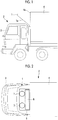
Fig. 1 is a side view of a vehicle on which a refrigerating unit for transportation according to a first embodiment is mounted. -
Fig. 2 is a plan view ofFig. 1 . -
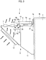
Fig. 3 is a schematic side view of the refrigerating unit for transportation according to the first embodiment. -
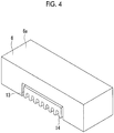
Fig. 4 is a schematic perspective view of a control box according to the first embodiment. -
Fig. 5 is a schematic perspective view showing a main portion of the refrigerating unit for transportation according to the first embodiment. -
Fig. 6 is a schematic side view of a refrigerating unit for transportation according to a second embodiment. Description of Embodiments - Hereinafter, embodiments according to the present invention will be described with reference to the drawings.
- Hereinafter, a first embodiment of the present invention will be described with reference to
Figs. 1 to 5 . - As shown in
Figs. 1 and 2 , avehicle 2 on which a refrigerating unit fortransportation 1 according to the present embodiment is mounted is a transportation truck in which a traveling engine (not shown) is disposed below acab 3. Thecab 3 is rotatable by a predetermined angle about a shaft (not shown) extending in a vehicle width direction at a lower portion of a front end. In thevehicle 2, avan body 4 is mounted on a frame which extends in a front-rear direction behind thecab 3. Loads such as frozen and refrigerated items are loaded in thevan body 4. - As shown in
Figs. 1 and 2 , the refrigerating unit fortransportation 1 is provided on an upper portion of afront surface 4a of thevan body 4 so as to protrude to a portion above thecab 3 over an approximately entire region in the vehicle width direction. The refrigerating unit fortransportation 1 supplies generated cool air into thevan body 4 so as to maintain a temperature in thevan body 4 to a constant temperature. - As shown in
Figs. 1 and3 , the refrigerating unit fortransportation 1 includes arefrigerating device 5 which is fixed to thevan body 4, acontrol box 6 which is installed on anupper surface 5a of therefrigerating device 5, and anair guide portion 8 which forms a portion of anair guide passage 20 described later. The refrigerating unit fortransportation 1 has an approximately right triangle shape when viewed from a side, and afront surface 1a is inclined so that a length thereof in the front-rear direction decreases from an upper side to a lower side. That is, the shape of the refrigerating unit fortransportation 1 1 is made such that thecab 3 and the refrigerating unit fortransportation 1 do not interfere with each other when the above-describedcab 3 is rotated. A plurality of air holes through which air is introduced into the refrigerating unit fortransportation 1 are formed on thefront surface 1a of the refrigerating unit fortransportation 1. - The refrigerating
device 5 is attached to thefront surface 4a of thevan body 4, and includes twocondenser fans 7 which are provided to be arranged right and left in front of an electric compressor (not shown), an evaporator (not shown), and thecontrol box 6, a refrigeratingdevice body portion 11 in which a generator (not shown) generating electricity by a drive force of the traveling engine or the like is accommodated, and acondenser 12 which is positioned in front of the refrigeratingdevice body portion 11 and is disposed along thefront surface 1a of the refrigerating unit fortransportation 1. The electric compressor, the evaporator, or the like disposed inside the refrigeratingdevice body portion 11 and thecondenser 12 are connected to each other via a refrigerant pipe (not shown), and constitute a refrigerating cycle. - The two
condenser fans 7 are disposed such that they are arranged in the vehicle width direction above thecondenser 12 and in front of the control box 6 (refer toFigs. 2 and3 ) and are rotated about vertical axes of the vehicle so as to discharge air inside the refrigerating unit fortransportation 1 to the outside. - The
control box 6 has an approximately rectangular box shape extending in the vehicle width direction, and is disposed on an upper surface of the refrigeratingdevice body portion 11 such that that a rear surface of thecontrol box 6 and thefront surface 4a of thevan body 4 are separated from each other. A front end of thecontrol box 6 is positioned in front of a front end of therefrigerating device 5. Anupper surface 6a of thecontrol box 6 is lower than anupper surface 4b of thevan body 4. A control device (not shown) is housed inside thecontrol box 6, and the control device controls therefrigerating device 5 such as an inverter device and an AC/DC converter (for example, a three-phase full wave rectifier using a diode). - The
control box 6 is formed of an aluminum alloy or the like which is lightweight and has improved heat conductivity. Moreover, as shown inFigs. 4 and5 , a recessedportion 13 which extends in the front-rear direction and is recessed upward is formed on a lower surface at an approximately center of thecontrol box 6 in the vehicle width direction over the entire region in the front-rear direction. In the recessedportion 13, aheat radiating fin 14 for cooling a heating part such as an inverter device and an AC/DC converter housed in thecontrol box 6 is integrally provided with thecontrol box 6. Theheat radiating fin 14 is a flat plate shape extending in the vehicular front-rear direction (that is, a direction in which the recessedportion 13 extends) and is formed of an aluminum alloy having improved heat conductivity. In addition, a raw material of each of thecontrol box 6 and theheat radiating fin 14 is not limited to the aluminum alloy. For example, the control box may be formed of a steel plate having iron as a raw material. In addition, inFig. 5 , the heat radiating fin 14 (refer toFig. 4 ) is not shown. - As shown in
Fig. 3 , theair guide portion 8 includes a firstair guide plate 15 which extends forward from an upper front surface of therefrigerating device 5, and a secondair guide plate 16 which extend forward from an upper surface of the recessedportion 13 of thecontrol box 6. The firstair guide plate 15 includes a flat plate-shapedlower surface portion 15a, and side surface portions (not show) which are erected upward from both ends of thelower surface portion 15a in the vehicle width direction. - The second
air guide plate 16 includes a firsthorizontal portion 16a which extends forward from the upper surface of the recessedportion 13, avertical portion 16b which extend downward from a front end of the firsthorizontal portion 16a, and a secondhorizontal portion 16c which extends forward from thevertical portion 16b. Both ends of the firsthorizontal portion 16a, thevertical portion 16b, and the secondhorizontal portion 16c in the vehicle width direction are connected to upper ends of the side surface portions. That is, a duct-shaped closed space is formed inside by the firstair guide plate 15 and the secondair guide plate 16. - In addition, in the
air guide portion 8, as partially shown by a broken line inFig. 5 , both end portions of theair guide portion 8 in the vehicle width direction are curved or inclined such that the width of theair guide portion 8 in the vehicle width direction increases forward. A right front end and a left front end of theair guide portion 8 are respectively installed around thecondenser fans 7 provided right and left, and openings are formed on the right front end and the left front end of theair guide portion 8. That is,air guide portion 8 is open to face the entireties in the vehicle width direction of thecondenser fans 7 arranged right and left. - The
air guide passage 20 formed by the recessedportion 13 of thecontrol box 6 and theair guide portion 8 will be described. As described above, the recessedportion 13 is formed such that the lower surface of thecontrol box 6 installed on theupper surface 5a of therefrigerating device 5 is recessed upward and is formed to extend in the front-rear direction over the entire region of thecontrol box 6 in the front-rear direction. In addition, thecontrol box 6 is disposed so as to be separated from thevan body 4 positioned behind thecontrol box 6. Accordingly, the recessedportion 13 has a duct structure which has openings in a front end portion and a rear end portion thereof and extends in the front-rear direction. - The above-described
air guide portion 8 extends to the vicinities of thecondenser fans 7 in a duct shape from the front end portion of the recessedportion 13. Accordingly, the recessedportion 13 and theair guide portion 8 are connected to each other, and thus, theair guide passage 20 is formed in which the recessedportion 13 is set to an upstream portion and theair guide portion 8 is a downstream portion. In theair guide passage 20, the rear end portion of the recessedportion 13 is set to anintake port 21 through which outside air is introduced into theair guide passage 20 and openings formed on the right front end and the left front end of theair guide portion 8 are set to adischarge port 22 through which the introduced air is discharged. The end portion of the firstair guide plate 15 on thedischarge port 22 side extends to a portion vertically below a wing portion of thecondenser fan 7. - Next, a flow of air passing through the refrigerating unit for
transportation 1 will be described. As shown by solid arrows and dashed arrows inFigs. 3 and5 , if thecondenser fans 7 are driven, outside air around the front surface of the refrigerating unit fortransportation 1 passes through air holes formed on the front surface of the refrigerating unit fortransportation 1 and thecondenser 12, and thereafter, is discharged from thecondenser fans 7 to the outside of the refrigerating unit fortransportation 1. In addition, if thecondenser fans 7 are driven, air around thedischarge port 22 is sucked to thecondenser fan 7 side, and thus, a flow is formed in theair guide passage 20. Accordingly, outside air around the upper surface of the refrigerating unit fortransportation 1 is guided to a space between thevan body 4 and thecontrol box 6, flows from theintake port 21 of the rear end portion of thecontrol box 6 into theair guide passage 20, and is discharged from thedischarge port 22. The outside air discharged from thedischarge port 22 is guided upward as it is (refer toFigs. 3 and5 ) and is discharged from thecondenser fans 7 to the outside of the refrigerating unit fortransportation 1. - According to the present embodiment, the following effects are exerted.
- The outside air flows through the
heat radiating fin 14 for cooling the control device in thecontrol box 6 through theair guide passage 20, and thus, it is possible to cool the control device by heat exchange between theheat radiating fin 14 and the outside air. - In addition, compared to a case where exhaust air of the
condenser 12 flows through theheat radiating fin 14, the outside air having a relatively low temperature flows through theheat radiating fin 14, and thus, it is possible to cool the control device by a small-sizedheat radiating fin 14. - In addition, the outside air which has passed through the
heat radiating fin 14 through theair guide passage 20 is guided to thecondenser fans 7, and thus, the outside air cooling the control device can flow through theheat radiating fin 14 by thecondenser fans 7, and the outside air can flow through theheat radiating fin 14 even in any vehicle traveling state (for example, a vehicle stopped state) so as to cool the control device. - In addition, the
condenser fans 7 are used in order to cause the outside air to flow through theheat radiating fin 14 cooling the control device, and thus, it is not necessary to newly provide other fans or the like, and it is possible to decrease the number of parts. - When the vehicle travels, a high-temperature exhaust air is discharged from the traveling engine disposed below the
cab 3. The discharged exhaust air flows the rear side of thecab 3 by running wind of the vehicle and rises along thefront surface 4a of thevan body 4. However, in the above-described configuration, the refrigeratingdevice 5 is attached to thefront surface 4a of thevan body 4, theair guide passage 20 is provided on theupper surface 5a of the refrigerating device 5 (refer toFig. 3 ), and thus, the rising exhaust air is blocked by the refrigeratingdevice 5, and the exhaust air does not reach theair guide passage 20. Accordingly, the exhaust air of the traveling engine is not easily mixed with the outside air sucked from theintake port 21, and thus, when the vehicle travels, the outside air flowing through theair guide passage 20 can be maintained at a low temperature, and it is possible to suitably cool the control device in thecontrol box 6. - The
upper surface 6a of thecontrol box 6 is lower than theupper surface 4b of the van body 4 (refer toFig. 3 ). Accordingly, a portion of wind (for example, running wind) from the front of the vehicle toward the rear of the vehicle passes through a portion above thecontrol box 6 and abuts against the upper portion of the front surface of thevan body 4. If the wind abuts against the upper portion of the front surface of thevan body 4, a pressure around the upper portion increases. Theintake port 21 is open between thecontrol box 6 and thevan body 4, a pressure difference between theintake port 21 and thedischarge port 22 increases, and thus, much outside air can be guided to theair guide passage 20. Accordingly, more much outside air can flow through theheat radiating fin 14, much outside air and theheat radiating fin 14 can be heat-exchanged with each other, and thus, it is possible to more suitably cool the control device. - The recessed
portion 13 is formed in thecontrol box 6, and theheat radiating fin 14 is disposed in the recessed portion 13 (refer toFig. 4 ). Accordingly, a height of thecontrol box 6 can be set regardless of a height of theheat radiating fin 14. Therefore, it is possible to suppress the height of thecontrol box 6, and it is possible to suppress a height of the refrigerating unit fortransportation 1. - In addition, it is possible to decrease the height of the
control box 6 disposed above the refrigeratingdevice 5, and thus, the refrigeratingdevice 5 can be disposed at a relatively upper portion of thevan body 4. An outlet (not shown) through which cool air generated by the refrigeratingdevice 5 is blown to the inside of thevan body 4 is provided inside thevan body 4. The refrigeratingdevice 5 can be disposed at a relatively upper portion, and thus, the outlet can be disposed at a relatively upper portion in thevan body 4. Accordingly, in case where a package is loaded in the van body, it is possible to make it difficult for the outlet and the package interfere with each other. - In addition, the recessed
portion 13 is formed on the lower surface of thecontrol box 6 along the control device, and the recessedportion 13 is recessed upward. Accordingly, in a case where outside air flow through theheat radiating fin 14, the recessedportion 13 of thecontrol box 6 can be a portion of theair guide passage 20. Therefore, it is not necessary to newly provide a part such as a duct exclusively for the air guide passage, and it is possible to form theair guide passage 20 while decreasing the number of parts. - The two
condenser fans 7 are provided and theair guide passage 20 extends to the vicinity of each of the condenser fans 7 (refer toFig. 5 ). Accordingly, even in a case where onecondenser fan 7 is failed, outside air can be guided from theintake port 21 to theair guide passage 20 by theother condenser fan 7 to cool the control device. - The first
air guide plate 15 and the secondair guide plate 16 forming theair guide passage 20 extend to the vicinity of each of thecondenser fans 7. Accordingly, it is possible to introduce the outside air to theair guide passage 20 and guide the outside air to theheat radiating fin 14 more reliably so as to cool the control device. - In addition, in the present embodiment, the first
air guide plate 15 extends to the portion vertically below eachcondenser fan 7. However, the firstair guide plate 15 may not extend to the portion vertically below thecondenser fan 7. The first air guide plate or the secondair guide plate 16 may not extend to the vicinity of eachcondenser fan 7. Preferably, the vicinity is within 50 mm from an end of the wing portion of thecondenser fan 7 in a plan view. - Moreover, in the present embodiment, the front end of the
control box 6 is positioned in front of the front end of therefrigerating device 5. A positional relationship between thecontrol box 6 and therefrigerating device 5 is not limited to this. The front end of thecontrol box 6 may be aligned with the front end of therefrigerating device 5 or the front end of thecontrol box 6 may be positioned behind the front end of therefrigerating device 5. Even in the case, the firsthorizontal portion 16a of the secondair guide plate 16 extends forward from the upper surface of the recessedportion 13 formed in thecontrol box 6, and thus, the firsthorizontal portion 16a further extends than the configuration described in the present embodiment (the configuration in which the front end of thecontrol box 6 is positioned in front of the front end of the refrigerating device 5) so as to form theair guide passage 20. - Next, a second embodiment of the present invention will be described with reference to
Fig. 6 . - Compared to the above-described first embodiment, in the present embodiment, a disposition between the
control box 6, thecondenser fan 7, and theair guide portion 8 or the like is different. Descriptions of matters similar to those of the first embodiment are omitted. - As shown in
Fig. 6 , in the refrigerating unit fortransportation 1 according to the present embodiment, thecondenser fan 7 is disposed above the refrigeratingdevice 5 and thecontrol box 6 is disposed in front of thecondenser fan 7. In addition, theair guide portion 8 according to the present embodiment includes the firstair guide plate 15 which extends rearward from the lower surface of thecontrol box 6 and a secondair guide plate 16 which extends to be approximately parallel to the firstair guide plate 15 rearward from the upper surface of the recessedportion 13. Both end portions of the firstair guide plate 15 in the vehicle width direction are erected upward and are connected to the secondair guide plate 16 at the upper end portions. - A flow of air passing through the refrigerating unit for
transportation 1 according to the present embodiment will be described. As shown by arrows inFig. 6 , if thecondenser fan 7 is driven, the outside air around the front surface of the refrigerating unit fortransportation 1 passes through the air holes formed on the front surface of the refrigerating unit fortransportation 1 and thecondenser 12, and thereafter, is guided obliquely rearward and upward, and is discharged from thecondenser fan 7 to the outside of the refrigerating unit fortransportation 1. In addition, if thecondenser fan 7 is driven, the outside air around the front surface of thecontrol box 6 flows from theintake port 21 of the front surface of the control box into theair guide passage 20 and is discharged from thedischarge port 22. The outside air discharged from thedischarge port 22 is guided upward as it is and is discharged from thecondenser fan 7 to the outside of the refrigerating unit fortransportation 1. - According to the present embodiment, the following effects are exerted.
- The
air guide passage 20 is positioned in front of thecondenser fan 7 and theintake port 21 is open forward. Accordingly, a dynamic pressure of wind (for example, the running wind of the vehicle) from the front of the vehicle toward the rear of the vehicle is used, and thus, the outside air is easily introduced into theintake port 21, and much outside air can be introduced to the air guide passage to flow through theheat radiating fin 14. Accordingly, much outside air and theheat radiating fin 14 can be heat-exchanged, and thus, it is possible to suitably cool thecontrol box 6. - In addition, when the vehicle travels, a high-temperature exhaust air is discharged from the traveling engine, and thus, the exhaust air flows from the exhaust port toward the rear of the vehicle by the running wind of the vehicle. In the above-described configuration, the
air guide passage 20 is positioned in the front portion of thevehicle 2 and theintake port 21 is open forward, and thus, the exhaust air of the traveling engine is not easily mixed with the outside air sucked from theintake port 21. Accordingly, when the vehicle travels, the outside air flowing through theair guide passage 20 can be maintained at a low temperature, and it is possible to suitably cool thecontrol box 6. - Moreover, the present invention is not limited to the inventions according to the above-described first embodiment and second embodiment, and can be appropriately modified within a scope which does not depart from the gist. For example, in the above-described first and second embodiments, two
condenser fans 7 are provided. However, the number of thecondenser fans 7 may be one or three or more. -
- 1: refrigerating unit for transportation
- 4: van body
- 5: refrigerating device
- 6: control box
- 7: condenser fan
- 8: air guide portion
- 12: condenser
- 13: recessed portion
- 14: heat radiating fin
- 15: first air guide plate
- 16: second air guide plate
- 20: air guide passage
- 21: intake port
- 22: discharge port
Claims (7)
- A refrigerating unit for transportation comprising:a refrigerating device which is attached to a front surface of a van body and includes a condenser and a condenser fan which discharges air which has passed through the condenser;a control device which controls the refrigerating device;a control box which includes a heat radiating fin for cooling the control device on an outer surface of the control box and houses the control device; andan air guide passage through which outside air is guided to the heat radiating fin and outside air which has passed through the heat radiating fin is guided to an intake side of the condenser fan.
- The refrigerating unit for transportation according to claim 1,
wherein the air guide passage includes an intake port through which the outside air is introduced and is positioned behind the condenser fan,
wherein the refrigerating device is attached to the front surface of the van body,
wherein the control box is disposed on an upper surface of the refrigerating device so as to be separated from the front surface of the van body, and
wherein the intake port is open between the control box and the front surface of the van body. - The refrigerating unit for transportation according to claim 2,
wherein an upper surface of the control box is lower than an upper surface of the van body. - The refrigerating unit for transportation according to claim 1,
wherein the air guide passage includes an intake port through which the outside air is sucked and is positioned in front of the condenser fan, and
wherein the intake port is open forward. - The refrigerating unit for transportation according to any one of claims 1 to 4,
wherein a recessed portion which is recessed upward along the control device is formed on a lower surface of the control box,
wherein the heat radiating fin is disposed in the recessed portion, and
wherein the recessed portion constitutes a portion of the air guide passage. - The refrigerating unit for transportation according to any one of claims 1 to 5,
wherein a plurality of the condenser fans are provided, and
wherein the air guide passage communicates with each of the plurality of condenser fans. - The refrigerating unit for transportation according to any one of claims 1 to 6,
wherein the air guide passage is formed by an air guide plate, and
wherein the air guide plate extends to the vicinity of the condenser fan.
Applications Claiming Priority (2)
| Application Number | Priority Date | Filing Date | Title |
|---|---|---|---|
| JP2016122102A JP6186578B1 (en) | 2016-06-20 | 2016-06-20 | Transport refrigeration unit |
| PCT/JP2017/022224 WO2017221814A1 (en) | 2016-06-20 | 2017-06-15 | Refrigerating unit for transportation |
Publications (3)
| Publication Number | Publication Date |
|---|---|
| EP3415844A1 true EP3415844A1 (en) | 2018-12-19 |
| EP3415844A4 EP3415844A4 (en) | 2019-05-01 |
| EP3415844B1 EP3415844B1 (en) | 2020-08-05 |
Family
ID=59720288
Family Applications (1)
| Application Number | Title | Priority Date | Filing Date |
|---|---|---|---|
| EP17815282.3A Active EP3415844B1 (en) | 2016-06-20 | 2017-06-15 | Refrigerating unit for transportation |
Country Status (3)
| Country | Link |
|---|---|
| EP (1) | EP3415844B1 (en) |
| JP (1) | JP6186578B1 (en) |
| WO (1) | WO2017221814A1 (en) |
Cited By (3)
| Publication number | Priority date | Publication date | Assignee | Title |
|---|---|---|---|---|
| CN110303292A (en) * | 2019-04-17 | 2019-10-08 | 东莞市德铫实业有限公司 | Aluminum radiating fin manufacturing and forming process |
| EP4095461A4 (en) * | 2020-03-06 | 2023-07-12 | Daikin Industries, Ltd. | REFRIGERATOR USED IN TRANSPORT AND TRANSPORT CONTAINER |
| EP4342706A1 (en) * | 2022-09-16 | 2024-03-27 | Carrier Corporation | Cooling system for a variable frequency drive in a transport refrigeration unit |
Families Citing this family (4)
| Publication number | Priority date | Publication date | Assignee | Title |
|---|---|---|---|---|
| JP6942584B2 (en) * | 2017-09-25 | 2021-09-29 | 三菱重工サーマルシステムズ株式会社 | Freezing unit for transportation |
| KR102563739B1 (en) * | 2018-06-20 | 2023-08-17 | 한온시스템 주식회사 | Vehicle electrical equipment cooling system |
| WO2023073891A1 (en) | 2021-10-28 | 2023-05-04 | 三菱重工サーマルシステムズ株式会社 | Transport refrigeration unit |
| JP2025158843A (en) * | 2024-04-05 | 2025-10-17 | 三菱重工サーマルシステムズ株式会社 | High-voltage circuit unit and transport refrigeration machine |
Family Cites Families (10)
| Publication number | Priority date | Publication date | Assignee | Title |
|---|---|---|---|---|
| JPH062993U (en) * | 1992-06-12 | 1994-01-14 | 日新電機株式会社 | Inverter element cooling device |
| JPH08163877A (en) * | 1994-12-05 | 1996-06-21 | Nippondenso Co Ltd | Power converter and manufacture thereof |
| JPH10294579A (en) * | 1997-04-18 | 1998-11-04 | Sansha Electric Mfg Co Ltd | Power supply |
| JP2003097881A (en) * | 2001-09-20 | 2003-04-03 | Mitsubishi Heavy Ind Ltd | Refrigeration unit for container |
| JP2008128540A (en) * | 2006-11-20 | 2008-06-05 | Denso Corp | Refrigerator unit for refrigerator |
| US20120031132A1 (en) * | 2009-05-25 | 2012-02-09 | Makoto Ikemiya | Trailer refrigerating apparatus |
| JP2011257087A (en) * | 2010-06-10 | 2011-12-22 | Denso Corp | Refrigerating device for freezer |
| JP5754917B2 (en) * | 2010-11-05 | 2015-07-29 | 三菱重工業株式会社 | Refrigeration unit for vehicle transportation |
| JP5940372B2 (en) * | 2012-05-21 | 2016-06-29 | シャープ株式会社 | Lighting device |
| WO2015045252A1 (en) * | 2013-09-30 | 2015-04-02 | ダイキン工業株式会社 | Refrigeration device for container |
-
2016
- 2016-06-20 JP JP2016122102A patent/JP6186578B1/en active Active
-
2017
- 2017-06-15 EP EP17815282.3A patent/EP3415844B1/en active Active
- 2017-06-15 WO PCT/JP2017/022224 patent/WO2017221814A1/en not_active Ceased
Cited By (4)
| Publication number | Priority date | Publication date | Assignee | Title |
|---|---|---|---|---|
| CN110303292A (en) * | 2019-04-17 | 2019-10-08 | 东莞市德铫实业有限公司 | Aluminum radiating fin manufacturing and forming process |
| EP4095461A4 (en) * | 2020-03-06 | 2023-07-12 | Daikin Industries, Ltd. | REFRIGERATOR USED IN TRANSPORT AND TRANSPORT CONTAINER |
| US12215915B2 (en) | 2020-03-06 | 2025-02-04 | Daikin Industries, Ltd. | Refrigeration apparatus for transport and transport container |
| EP4342706A1 (en) * | 2022-09-16 | 2024-03-27 | Carrier Corporation | Cooling system for a variable frequency drive in a transport refrigeration unit |
Also Published As
| Publication number | Publication date |
|---|---|
| JP6186578B1 (en) | 2017-08-30 |
| EP3415844A4 (en) | 2019-05-01 |
| WO2017221814A1 (en) | 2017-12-28 |
| EP3415844B1 (en) | 2020-08-05 |
| JP2017227352A (en) | 2017-12-28 |
Similar Documents
| Publication | Publication Date | Title |
|---|---|---|
| EP3415844B1 (en) | Refrigerating unit for transportation | |
| US11239508B2 (en) | Battery pack | |
| JP6667210B2 (en) | Transport refrigerators and trailers | |
| JP6308009B2 (en) | Battery pack | |
| US10403868B2 (en) | Battery | |
| EP2174082B1 (en) | Evaporator air management system for trailer refrigeration | |
| EP2710868B1 (en) | Variable frequency drive heat sink assembly | |
| US20090266508A1 (en) | Cooling apparatus for a fuel cell powered vehicle | |
| US8701811B2 (en) | Battery cooling system and method | |
| US6978628B2 (en) | Air conditioning device for vehicle | |
| US11198345B2 (en) | Method and apparatus for cooling and heating in a vehicle | |
| US7730734B2 (en) | Cooling apparatus of a fuel cell vehicle | |
| JP5024353B2 (en) | Cooling system for electrical equipment | |
| US20120031132A1 (en) | Trailer refrigerating apparatus | |
| US20050155559A1 (en) | Engine-driven work machine | |
| JP5440826B2 (en) | Outside air introduction grill | |
| JP5754917B2 (en) | Refrigeration unit for vehicle transportation | |
| JP6559537B2 (en) | Fuel cell vehicle | |
| JP2018017445A (en) | Transport refrigeration unit | |
| CN107953740B (en) | air conditioning unit | |
| JP5947071B2 (en) | Battery cooling system | |
| CN114619980B (en) | Lower cover structure of vehicle | |
| JP7316119B2 (en) | electric car air conditioning system | |
| CN108140469A (en) | Vehicle transformer | |
| JP6586347B2 (en) | Wind deflector |
Legal Events
| Date | Code | Title | Description |
|---|---|---|---|
| STAA | Information on the status of an ep patent application or granted ep patent |
Free format text: STATUS: THE INTERNATIONAL PUBLICATION HAS BEEN MADE |
|
| PUAI | Public reference made under article 153(3) epc to a published international application that has entered the european phase |
Free format text: ORIGINAL CODE: 0009012 |
|
| STAA | Information on the status of an ep patent application or granted ep patent |
Free format text: STATUS: REQUEST FOR EXAMINATION WAS MADE |
|
| 17P | Request for examination filed |
Effective date: 20180914 |
|
| AK | Designated contracting states |
Kind code of ref document: A1 Designated state(s): AL AT BE BG CH CY CZ DE DK EE ES FI FR GB GR HR HU IE IS IT LI LT LU LV MC MK MT NL NO PL PT RO RS SE SI SK SM TR |
|
| AX | Request for extension of the european patent |
Extension state: BA ME |
|
| A4 | Supplementary search report drawn up and despatched |
Effective date: 20190401 |
|
| RIC1 | Information provided on ipc code assigned before grant |
Ipc: F25D 19/00 20060101AFI20190326BHEP Ipc: F25D 11/00 20060101ALI20190326BHEP Ipc: H05K 7/20 20060101ALI20190326BHEP Ipc: F25B 31/00 20060101ALI20190326BHEP Ipc: H01L 23/467 20060101ALI20190326BHEP |
|
| DAV | Request for validation of the european patent (deleted) | ||
| DAX | Request for extension of the european patent (deleted) | ||
| REG | Reference to a national code |
Ref country code: DE Ref legal event code: R079 Ref document number: 602017021317 Country of ref document: DE Free format text: PREVIOUS MAIN CLASS: F25D0019000000 Ipc: F25B0031000000 |
|
| RIC1 | Information provided on ipc code assigned before grant |
Ipc: H01L 23/467 20060101ALI20200103BHEP Ipc: B60H 1/32 20060101ALI20200103BHEP Ipc: F25D 19/00 20060101ALI20200103BHEP Ipc: F25B 31/00 20060101AFI20200103BHEP |
|
| GRAP | Despatch of communication of intention to grant a patent |
Free format text: ORIGINAL CODE: EPIDOSNIGR1 |
|
| STAA | Information on the status of an ep patent application or granted ep patent |
Free format text: STATUS: GRANT OF PATENT IS INTENDED |
|
| INTG | Intention to grant announced |
Effective date: 20200306 |
|
| GRAS | Grant fee paid |
Free format text: ORIGINAL CODE: EPIDOSNIGR3 |
|
| GRAA | (expected) grant |
Free format text: ORIGINAL CODE: 0009210 |
|
| STAA | Information on the status of an ep patent application or granted ep patent |
Free format text: STATUS: THE PATENT HAS BEEN GRANTED |
|
| AK | Designated contracting states |
Kind code of ref document: B1 Designated state(s): AL AT BE BG CH CY CZ DE DK EE ES FI FR GB GR HR HU IE IS IT LI LT LU LV MC MK MT NL NO PL PT RO RS SE SI SK SM TR |
|
| REG | Reference to a national code |
Ref country code: GB Ref legal event code: FG4D |
|
| REG | Reference to a national code |
Ref country code: CH Ref legal event code: EP |
|
| REG | Reference to a national code |
Ref country code: AT Ref legal event code: REF Ref document number: 1299280 Country of ref document: AT Kind code of ref document: T Effective date: 20200815 |
|
| REG | Reference to a national code |
Ref country code: DE Ref legal event code: R096 Ref document number: 602017021317 Country of ref document: DE |
|
| REG | Reference to a national code |
Ref country code: IE Ref legal event code: FG4D |
|
| REG | Reference to a national code |
Ref country code: LT Ref legal event code: MG4D |
|
| REG | Reference to a national code |
Ref country code: NL Ref legal event code: MP Effective date: 20200805 |
|
| REG | Reference to a national code |
Ref country code: AT Ref legal event code: MK05 Ref document number: 1299280 Country of ref document: AT Kind code of ref document: T Effective date: 20200805 |
|
| PG25 | Lapsed in a contracting state [announced via postgrant information from national office to epo] |
Ref country code: FI Free format text: LAPSE BECAUSE OF FAILURE TO SUBMIT A TRANSLATION OF THE DESCRIPTION OR TO PAY THE FEE WITHIN THE PRESCRIBED TIME-LIMIT Effective date: 20200805 Ref country code: HR Free format text: LAPSE BECAUSE OF FAILURE TO SUBMIT A TRANSLATION OF THE DESCRIPTION OR TO PAY THE FEE WITHIN THE PRESCRIBED TIME-LIMIT Effective date: 20200805 Ref country code: BG Free format text: LAPSE BECAUSE OF FAILURE TO SUBMIT A TRANSLATION OF THE DESCRIPTION OR TO PAY THE FEE WITHIN THE PRESCRIBED TIME-LIMIT Effective date: 20201105 Ref country code: LT Free format text: LAPSE BECAUSE OF FAILURE TO SUBMIT A TRANSLATION OF THE DESCRIPTION OR TO PAY THE FEE WITHIN THE PRESCRIBED TIME-LIMIT Effective date: 20200805 Ref country code: ES Free format text: LAPSE BECAUSE OF FAILURE TO SUBMIT A TRANSLATION OF THE DESCRIPTION OR TO PAY THE FEE WITHIN THE PRESCRIBED TIME-LIMIT Effective date: 20200805 Ref country code: NO Free format text: LAPSE BECAUSE OF FAILURE TO SUBMIT A TRANSLATION OF THE DESCRIPTION OR TO PAY THE FEE WITHIN THE PRESCRIBED TIME-LIMIT Effective date: 20201105 Ref country code: GR Free format text: LAPSE BECAUSE OF FAILURE TO SUBMIT A TRANSLATION OF THE DESCRIPTION OR TO PAY THE FEE WITHIN THE PRESCRIBED TIME-LIMIT Effective date: 20201106 Ref country code: PT Free format text: LAPSE BECAUSE OF FAILURE TO SUBMIT A TRANSLATION OF THE DESCRIPTION OR TO PAY THE FEE WITHIN THE PRESCRIBED TIME-LIMIT Effective date: 20201207 Ref country code: AT Free format text: LAPSE BECAUSE OF FAILURE TO SUBMIT A TRANSLATION OF THE DESCRIPTION OR TO PAY THE FEE WITHIN THE PRESCRIBED TIME-LIMIT Effective date: 20200805 Ref country code: SE Free format text: LAPSE BECAUSE OF FAILURE TO SUBMIT A TRANSLATION OF THE DESCRIPTION OR TO PAY THE FEE WITHIN THE PRESCRIBED TIME-LIMIT Effective date: 20200805 |
|
| PG25 | Lapsed in a contracting state [announced via postgrant information from national office to epo] |
Ref country code: RS Free format text: LAPSE BECAUSE OF FAILURE TO SUBMIT A TRANSLATION OF THE DESCRIPTION OR TO PAY THE FEE WITHIN THE PRESCRIBED TIME-LIMIT Effective date: 20200805 Ref country code: LV Free format text: LAPSE BECAUSE OF FAILURE TO SUBMIT A TRANSLATION OF THE DESCRIPTION OR TO PAY THE FEE WITHIN THE PRESCRIBED TIME-LIMIT Effective date: 20200805 Ref country code: NL Free format text: LAPSE BECAUSE OF FAILURE TO SUBMIT A TRANSLATION OF THE DESCRIPTION OR TO PAY THE FEE WITHIN THE PRESCRIBED TIME-LIMIT Effective date: 20200805 Ref country code: PL Free format text: LAPSE BECAUSE OF FAILURE TO SUBMIT A TRANSLATION OF THE DESCRIPTION OR TO PAY THE FEE WITHIN THE PRESCRIBED TIME-LIMIT Effective date: 20200805 Ref country code: IS Free format text: LAPSE BECAUSE OF FAILURE TO SUBMIT A TRANSLATION OF THE DESCRIPTION OR TO PAY THE FEE WITHIN THE PRESCRIBED TIME-LIMIT Effective date: 20201205 |
|
| PG25 | Lapsed in a contracting state [announced via postgrant information from national office to epo] |
Ref country code: SM Free format text: LAPSE BECAUSE OF FAILURE TO SUBMIT A TRANSLATION OF THE DESCRIPTION OR TO PAY THE FEE WITHIN THE PRESCRIBED TIME-LIMIT Effective date: 20200805 Ref country code: RO Free format text: LAPSE BECAUSE OF FAILURE TO SUBMIT A TRANSLATION OF THE DESCRIPTION OR TO PAY THE FEE WITHIN THE PRESCRIBED TIME-LIMIT Effective date: 20200805 Ref country code: DK Free format text: LAPSE BECAUSE OF FAILURE TO SUBMIT A TRANSLATION OF THE DESCRIPTION OR TO PAY THE FEE WITHIN THE PRESCRIBED TIME-LIMIT Effective date: 20200805 Ref country code: CZ Free format text: LAPSE BECAUSE OF FAILURE TO SUBMIT A TRANSLATION OF THE DESCRIPTION OR TO PAY THE FEE WITHIN THE PRESCRIBED TIME-LIMIT Effective date: 20200805 Ref country code: EE Free format text: LAPSE BECAUSE OF FAILURE TO SUBMIT A TRANSLATION OF THE DESCRIPTION OR TO PAY THE FEE WITHIN THE PRESCRIBED TIME-LIMIT Effective date: 20200805 |
|
| REG | Reference to a national code |
Ref country code: DE Ref legal event code: R097 Ref document number: 602017021317 Country of ref document: DE |
|
| PG25 | Lapsed in a contracting state [announced via postgrant information from national office to epo] |
Ref country code: AL Free format text: LAPSE BECAUSE OF FAILURE TO SUBMIT A TRANSLATION OF THE DESCRIPTION OR TO PAY THE FEE WITHIN THE PRESCRIBED TIME-LIMIT Effective date: 20200805 |
|
| PLBE | No opposition filed within time limit |
Free format text: ORIGINAL CODE: 0009261 |
|
| STAA | Information on the status of an ep patent application or granted ep patent |
Free format text: STATUS: NO OPPOSITION FILED WITHIN TIME LIMIT |
|
| PG25 | Lapsed in a contracting state [announced via postgrant information from national office to epo] |
Ref country code: SK Free format text: LAPSE BECAUSE OF FAILURE TO SUBMIT A TRANSLATION OF THE DESCRIPTION OR TO PAY THE FEE WITHIN THE PRESCRIBED TIME-LIMIT Effective date: 20200805 |
|
| 26N | No opposition filed |
Effective date: 20210507 |
|
| PG25 | Lapsed in a contracting state [announced via postgrant information from national office to epo] |
Ref country code: IT Free format text: LAPSE BECAUSE OF FAILURE TO SUBMIT A TRANSLATION OF THE DESCRIPTION OR TO PAY THE FEE WITHIN THE PRESCRIBED TIME-LIMIT Effective date: 20200805 |
|
| PG25 | Lapsed in a contracting state [announced via postgrant information from national office to epo] |
Ref country code: SI Free format text: LAPSE BECAUSE OF FAILURE TO SUBMIT A TRANSLATION OF THE DESCRIPTION OR TO PAY THE FEE WITHIN THE PRESCRIBED TIME-LIMIT Effective date: 20200805 |
|
| PG25 | Lapsed in a contracting state [announced via postgrant information from national office to epo] |
Ref country code: MC Free format text: LAPSE BECAUSE OF FAILURE TO SUBMIT A TRANSLATION OF THE DESCRIPTION OR TO PAY THE FEE WITHIN THE PRESCRIBED TIME-LIMIT Effective date: 20200805 |
|
| REG | Reference to a national code |
Ref country code: CH Ref legal event code: PL |
|
| GBPC | Gb: european patent ceased through non-payment of renewal fee |
Effective date: 20210615 |
|
| REG | Reference to a national code |
Ref country code: BE Ref legal event code: MM Effective date: 20210630 |
|
| PG25 | Lapsed in a contracting state [announced via postgrant information from national office to epo] |
Ref country code: LU Free format text: LAPSE BECAUSE OF NON-PAYMENT OF DUE FEES Effective date: 20210615 |
|
| PG25 | Lapsed in a contracting state [announced via postgrant information from national office to epo] |
Ref country code: LI Free format text: LAPSE BECAUSE OF NON-PAYMENT OF DUE FEES Effective date: 20210630 Ref country code: IE Free format text: LAPSE BECAUSE OF NON-PAYMENT OF DUE FEES Effective date: 20210615 Ref country code: GB Free format text: LAPSE BECAUSE OF NON-PAYMENT OF DUE FEES Effective date: 20210615 Ref country code: CH Free format text: LAPSE BECAUSE OF NON-PAYMENT OF DUE FEES Effective date: 20210630 |
|
| PG25 | Lapsed in a contracting state [announced via postgrant information from national office to epo] |
Ref country code: BE Free format text: LAPSE BECAUSE OF NON-PAYMENT OF DUE FEES Effective date: 20210630 |
|
| REG | Reference to a national code |
Ref country code: DE Ref legal event code: R082 Ref document number: 602017021317 Country of ref document: DE Representative=s name: CBDL PATENTANWAELTE GBR, DE Ref country code: DE Ref legal event code: R082 Ref document number: 602017021317 Country of ref document: DE Representative=s name: CBDL PATENTANWAELTE EGBR, DE |
|
| PG25 | Lapsed in a contracting state [announced via postgrant information from national office to epo] |
Ref country code: CY Free format text: LAPSE BECAUSE OF FAILURE TO SUBMIT A TRANSLATION OF THE DESCRIPTION OR TO PAY THE FEE WITHIN THE PRESCRIBED TIME-LIMIT Effective date: 20200805 |
|
| PG25 | Lapsed in a contracting state [announced via postgrant information from national office to epo] |
Ref country code: HU Free format text: LAPSE BECAUSE OF FAILURE TO SUBMIT A TRANSLATION OF THE DESCRIPTION OR TO PAY THE FEE WITHIN THE PRESCRIBED TIME-LIMIT; INVALID AB INITIO Effective date: 20170615 |
|
| PG25 | Lapsed in a contracting state [announced via postgrant information from national office to epo] |
Ref country code: MK Free format text: LAPSE BECAUSE OF FAILURE TO SUBMIT A TRANSLATION OF THE DESCRIPTION OR TO PAY THE FEE WITHIN THE PRESCRIBED TIME-LIMIT Effective date: 20200805 |
|
| PG25 | Lapsed in a contracting state [announced via postgrant information from national office to epo] |
Ref country code: MT Free format text: LAPSE BECAUSE OF FAILURE TO SUBMIT A TRANSLATION OF THE DESCRIPTION OR TO PAY THE FEE WITHIN THE PRESCRIBED TIME-LIMIT Effective date: 20200805 |
|
| PGFP | Annual fee paid to national office [announced via postgrant information from national office to epo] |
Ref country code: DE Payment date: 20250429 Year of fee payment: 9 |
|
| PGFP | Annual fee paid to national office [announced via postgrant information from national office to epo] |
Ref country code: FR Payment date: 20250508 Year of fee payment: 9 |
|
| PG25 | Lapsed in a contracting state [announced via postgrant information from national office to epo] |
Ref country code: TR Free format text: LAPSE BECAUSE OF FAILURE TO SUBMIT A TRANSLATION OF THE DESCRIPTION OR TO PAY THE FEE WITHIN THE PRESCRIBED TIME-LIMIT Effective date: 20200805 |