EP3415802B1 - Expansion joint - Google Patents
Expansion joint Download PDFInfo
- Publication number
- EP3415802B1 EP3415802B1 EP17175959.0A EP17175959A EP3415802B1 EP 3415802 B1 EP3415802 B1 EP 3415802B1 EP 17175959 A EP17175959 A EP 17175959A EP 3415802 B1 EP3415802 B1 EP 3415802B1
- Authority
- EP
- European Patent Office
- Prior art keywords
- expansion joint
- gas
- chamber
- wall part
- wall
- Prior art date
- Legal status (The legal status is an assumption and is not a legal conclusion. Google has not performed a legal analysis and makes no representation as to the accuracy of the status listed.)
- Active
Links
Images


Classifications
-
- C—CHEMISTRY; METALLURGY
- C07—ORGANIC CHEMISTRY
- C07C—ACYCLIC OR CARBOCYCLIC COMPOUNDS
- C07C5/00—Preparation of hydrocarbons from hydrocarbons containing the same number of carbon atoms
- C07C5/32—Preparation of hydrocarbons from hydrocarbons containing the same number of carbon atoms by dehydrogenation with formation of free hydrogen
- C07C5/327—Formation of non-aromatic carbon-to-carbon double bonds only
-
- F—MECHANICAL ENGINEERING; LIGHTING; HEATING; WEAPONS; BLASTING
- F16—ENGINEERING ELEMENTS AND UNITS; GENERAL MEASURES FOR PRODUCING AND MAINTAINING EFFECTIVE FUNCTIONING OF MACHINES OR INSTALLATIONS; THERMAL INSULATION IN GENERAL
- F16L—PIPES; JOINTS OR FITTINGS FOR PIPES; SUPPORTS FOR PIPES, CABLES OR PROTECTIVE TUBING; MEANS FOR THERMAL INSULATION IN GENERAL
- F16L51/00—Expansion-compensation arrangements for pipe-lines
- F16L51/02—Expansion-compensation arrangements for pipe-lines making use of bellows or an expansible folded or corrugated tube
- F16L51/025—Expansion-compensation arrangements for pipe-lines making use of bellows or an expansible folded or corrugated tube with several corrugations
-
- F—MECHANICAL ENGINEERING; LIGHTING; HEATING; WEAPONS; BLASTING
- F16—ENGINEERING ELEMENTS AND UNITS; GENERAL MEASURES FOR PRODUCING AND MAINTAINING EFFECTIVE FUNCTIONING OF MACHINES OR INSTALLATIONS; THERMAL INSULATION IN GENERAL
- F16L—PIPES; JOINTS OR FITTINGS FOR PIPES; SUPPORTS FOR PIPES, CABLES OR PROTECTIVE TUBING; MEANS FOR THERMAL INSULATION IN GENERAL
- F16L51/00—Expansion-compensation arrangements for pipe-lines
- F16L51/02—Expansion-compensation arrangements for pipe-lines making use of bellows or an expansible folded or corrugated tube
- F16L51/026—Expansion-compensation arrangements for pipe-lines making use of bellows or an expansible folded or corrugated tube with interior reinforcement
-
- F—MECHANICAL ENGINEERING; LIGHTING; HEATING; WEAPONS; BLASTING
- F16—ENGINEERING ELEMENTS AND UNITS; GENERAL MEASURES FOR PRODUCING AND MAINTAINING EFFECTIVE FUNCTIONING OF MACHINES OR INSTALLATIONS; THERMAL INSULATION IN GENERAL
- F16L—PIPES; JOINTS OR FITTINGS FOR PIPES; SUPPORTS FOR PIPES, CABLES OR PROTECTIVE TUBING; MEANS FOR THERMAL INSULATION IN GENERAL
- F16L51/00—Expansion-compensation arrangements for pipe-lines
- F16L51/02—Expansion-compensation arrangements for pipe-lines making use of bellows or an expansible folded or corrugated tube
- F16L51/027—Expansion-compensation arrangements for pipe-lines making use of bellows or an expansible folded or corrugated tube with external reinforcement
-
- F—MECHANICAL ENGINEERING; LIGHTING; HEATING; WEAPONS; BLASTING
- F16—ENGINEERING ELEMENTS AND UNITS; GENERAL MEASURES FOR PRODUCING AND MAINTAINING EFFECTIVE FUNCTIONING OF MACHINES OR INSTALLATIONS; THERMAL INSULATION IN GENERAL
- F16L—PIPES; JOINTS OR FITTINGS FOR PIPES; SUPPORTS FOR PIPES, CABLES OR PROTECTIVE TUBING; MEANS FOR THERMAL INSULATION IN GENERAL
- F16L59/00—Thermal insulation in general
- F16L59/14—Arrangements for the insulation of pipes or pipe systems
- F16L59/147—Arrangements for the insulation of pipes or pipe systems the insulation being located inwardly of the outer surface of the pipe
Definitions
- the invention relates to an expansion joint for joining two adjacent parts of a pipe.
- said pipe can be part of a plant for producing propylene from propane gas, a process which is especially known under the Trademark CATOFIN®.
- An expansion joint for two adjacent parts of a pipe is an element which joins or connects the parts of the pipe in a flexible manner.
- an expansion joint can safely absorb heat-induced expansion and contraction of the adjacent parts of the pipe, e.g. to absorb vibration, to hold the parts together, or to allow a movement of the parts of the pipe due to thermal or mechanical stresses which can be compensated for by means of the expansion joint.
- Expansion joints are used e.g. in plants in which propylene can be produced from propane gas in a catalyst process by means of a dehydrogenation, wherein an amount of hydrogen is reduced in the propane. This process is an advantageous alternative to known production methods, which usually involve a cracking of crude oil in refineries.
- expansion joints there can be more than 20 expansion joints in such a plant for producing propylene from propane gas, in particular about 10 expansion joints in an inlet region and about 10 expansion joints in an outlet region.
- the expansion joints are critical elements of the plant and must fulfil their functions at very high temperatures, extreme flow velocities, and large cyclic movements.
- the two most common types of expansion joints in the plant are arranged in areas of an inlet header and an outlet header of the plant.
- Expansion joints which comprise an expansion bellows and an expanded wall designed to protect the expansion bellows from corrosion and damage due to overheating.
- the expansion bellows is welded onto the expanded wall, e.g. of an inlet pipe.
- An inner sleeve creates a chamber that separates the process fluid from the expanded wall and the bellows. Typically, this chamber is separated into two smaller chambers on either side of the expanded wall, wherein the two smaller chambers are filled with an insulation material. Due to differing thermal expansion coefficients of the materials involved, the two ends of the inner sleeve cannot be sealed. As a result, an opening is created, which allows process fluid to escape into the chamber. This can lead to an increase of temperature and creates a risk of coking. To solve this problem, solutions are known, according to which a channel that is created in a middle area between the insulation material chambers is constantly flushed with fresh propane gas.
- the fresh propane gas can enter a main flow channel for the process gas via the opening between the two ends of the inner sleeve.
- This can have a potential detrimental effect on the temperature of the process fluid and on the yield of producing propylene from the propane gas, due to the fact that the flushing fluid has to be at a lower temperature than the process fluid to provide cooling at the bellows.
- coking can occur due to hydrocarbon material stagnating in high-temperature dead zones that are created within the inner sleeve and the expanded wall.
- some olefins and di-olefins can be produced. At these temperatures and with sufficient residence time the olefins and di-olefins can convert to coke.
- Expansion joints for joining two adjacent parts of a pipe are disclosed in FR 2 124 846 A5 , EP 0 376 839 A1 , US 2015/084328 A1 or EP 0 028 742 A1 .
- an expansion joint for joining two adjacent parts of a pipe. e.g. made of stainless steel, is provided.
- the two adjacent parts of the pipe can be part of a plant for producing propylene from propane gas, a process which is especially known under the Trademark CATOFIN®.
- the expansion joint comprises an expansion bellows, e.g. made of stainless steel, an expanded wall and an inner sleeve assembly.
- the expanded wall comprises a first wall part, e.g. made of stainless steel, and a second wall part, e.g. made of stainless steel.
- the first wall part and the second wall part are spaced apart from each other axially by an axial gap.
- a first end face of the first wall part can face a second end face of the second wall part, wherein said first end face and said second end face are spaced apart from each other by the axial gap.
- the feature "expanded wall” particularly can mean that the wall is expanded in a radial direction compared to the two parts of the pipe, respectively, which can be joined by the expansion joint.
- the diameter of the expanded wall can be larger than the diameters of the two parts of the pipe of the pipe system which can be joined by the expansion joint.
- the first wall part of the expanded wall can be mechanically connected to one of the two adjacent parts of the pipe, and the second wall part of the expanded wall can be mechanically connected to the other one of the two adjacent parts of the pipe.
- the first wall part of the expanded wall can be a part of one of the two adjacent parts of the pipe, meaning that the first wall part and one of the two adjacent parts of the pipe are connected to each other in a one-piece manner.
- the second wall part of the expanded wall can be a part of the other one of the two adjacent parts of the pipe, meaning that the second wall part and the other one of the two adjacent parts of the pipe are connected to each other in a one-piece manner.
- the expansion bellows is connected to the first wall part, in particular welded onto the first wall part, and connected to the second wall part, in particular welded onto the second wall part, such that the axial gap between the first wall part and the second wall part is closed and such that the first wall part and the second wall part are connected flexibly.
- the feature "connected flexibly" can especially mean that the first wall part and the second wall part are connected such that stresses caused by axial, angular and lateral movements between the first wall part and the second wall part can be compensated for, wherein said stresses can occur due to high temperatures (e.g. 650° C) and high pressures (e.g. 2.9 bar) of propane gas flowing across the expansion joint during producing propylene from propane gas.
- the expansion bellows can be designed in an expanded manner with regards to a radial direction compared to the two parts of the pipe, which can be joined by the expansion joint.
- the diameter of the expansion bellows can be larger than the diameters of the two parts of the pipe which can be joined by the expansion joint.
- the expanded wall and the inner sleeve assembly limit at least one sealed chamber between each other, and the at least one sealed chamber is filled by a first gas.
- the sealed chamber can be adapted to be filled and to be pressurized by the first gas.
- the expansion joint according to the first aspect of the invention comprises a sealed chamber arrangement, in particular a pressurized sealed chamber arrangement, which enables that the expansion bellows is protected from a high temperature of a process fluid flowing across a flow channel within the expansion joint.
- the at least one sealed chamber helps to eliminate the presence of hydrocarbon in an area of the expansion bellows, thus helping to eliminate the potential for damage due to coke formation.
- the at least one sealed chamber can extend across the whole circumference of the expansion joint, meaning that the at least one sealed chamber extends 360° in a circumferential direction.
- the expansion joint according to the first aspect of the invention can particularly be used both in an inlet section as well as in an outlet section of a plant for producing propylene from propane gas, wherein a same expansion joint can be employed albeit at different sizes.
- the inner sleeve assembly comprises a first metal part, e.g. made of stainless steel, and a second metal part, e.g. made of stainless steel.
- the first metal part is connected to the first wall part, in particular welded onto the first wall part, such that the first metal part and the first wall part limit a first sealed chamber between each other.
- the second metal part can be connected to the second wall part, in particular can be welded onto the second wall part, such that the second metal part and the second wall part limit a second sealed chamber between each other.
- the first sealed chamber and the second sealed chamber are filled by the first gas.
- the first sealed chamber and the second sealed chamber are adapted to be filled and to be pressurized by the first gas. If the first sealed chamber and the second sealed chamber are filled, and preferably also pressurised by the first gas, they are able to balance stresses during temperature cycles of a process gas flowing across the pipes and the expansion joint.
- the at least one sealed chamber in particular the first sealed chamber and the second sealed chamber, can be filled with insulating material. This helps to further protect the expansion bellows from high temperatures within the flow channel.
- the expansion joint of the invention is characterized in that the inner sleeve assembly, in particular its first metal part and its second metal part, the expanded wall, in particular its first wall part and its second wall part, and the expansion bellows limit a third chamber between each other.
- the third chamber is adapted to be filled and pressurized with a second gas, such that an over pressure within the third chamber is higher than a process pressure of the second gas within a flow channel within the expansion joint.
- the flow channel is limited by the inner sleeve assembly, in particular a first interior wall surface provided by the first metal part and a second interior wall surface provided by the second metal part.
- the third chamber can be located between the first sealed chamber and the second sealed chamber in an axial direction of the expansion joint.
- the third chamber is in fluid connection with the flow channel which enables second gas from within the third chamber to leave the third chamber and to enter the flow channel. Due to the higher pressure within the third chamber compared to the flow channel, second gas from within the flow channel is hindered to enter the third chamber.
- the third chamber can be filled with and pressurized by the second gas, such that the second gas builds a barrier flow for the gas within the flow channel and that the third chamber acts as an hyperbaric pressure chamber compared to the flow channel.
- the second gas is the same sort of gas that flows through the flow channel, i.e. the process gas, in particular propane gas.
- the first metal part comprises a first additional bellows and the second metal part comprises a second additional bellows.
- the first additional bellows and the second additional bellows help to compensate for stresses that the pipes, the first metal part and the second metal part (which can be relatively thin compared to the pipes) are subjected to, in particular in areas of the first interior wall surface and the second interior wall surface.
- the first wall part comprises a first retaining ring assembly and the second wall part comprises a second retaining ring assembly.
- the first retaining ring assembly separates the first sealed chamber from the third chamber and the second retaining ring assembly separates the second sealed chamber from the third chamber.
- the first retaining ring assembly and the second retaining ring assembly can comprise monolithic parts. The inventors found out and verified by simulation that these monolithic parts enable that the first metal part and the second metal part withstand high temperature stresses which occur during process cycles within a plant for producing propylene from propane gas. At the same time, simulations showed that temperatures reaching the expansion bellows do not exceed a design temperature of the material of the expansion bellows.
- the first metal part can be bent 180° in a first bending area and the second metal part can be bent 180° in a second bending area, wherein the first bending area of the first metal part overlaps the second bending area of the second metal part such that pressurised second gas from within the third chamber can flow out of the third chamber into the flow channel.
- a first end of the first metal part is connected to, in particular welded onto the first wall part at a first connection position
- a second end of the first metal part is connected to, in particular welded onto the first wall part at a second connection position
- a first portion of the first metal part between the first connection position and the first bending area provides a first interior wall surface of the flow channel.
- a first end of the second metal part is connected to, in particular welded onto the second wall part at a third connection position
- a second end of the second metal part is connected to, in particular welded onto the second wall part at a fourth connection position
- a first portion of the second metal part between the third connection position and the second bending area provides a second interior wall surface of the flow channel.
- the inner sleeve of the expansion joint is formed by the first metal part, in particular by its first portion between the first connection position and the first bending area, and the second metal part, in particular by its first portion between the third connection position and the second bending area. Therefore, the first metal part serves to build the first sealed chamber as well as a part of the inner sleeve assembly, and the second metal part serves to build the second sealed chamber as well as another part of the inner sleeve assembly. Due to their aforesaid double functions, there is no need for an additional element which forms the inner sleeve assembly. Thus this embodiment helps to save parts, weight, manufacturing affords and costs.
- the expansion joint can further comprise first means for sensing pressure and second means for sensing pressure, wherein the first means for sensing pressure are adapted for measuring a first pressure, in particular a first pressure value, within the first sealed chamber, and wherein the second means for sensing pressure are adapted for measuring a second pressure, in particular a second pressure value, within the second sealed chamber.
- first means for sensing pressure are adapted for measuring a first pressure, in particular a first pressure value, within the first sealed chamber
- second means for sensing pressure are adapted for measuring a second pressure, in particular a second pressure value, within the second sealed chamber.
- first means for sensing pressure and the second means for sensing pressure can be adapted for generating data representing the measured pressure values, wherein the generated data can be transmitted e.g. to an electronic control unit for controlling a filling and pressurizing of the first sealed chamber and/or the second sealed chamber with the first gas.
- the expansion joint can comprise first gas supply means and second gas supply means, wherein the first gas supply means are adapted for filling and preferably also for pressurising the first sealed chamber with the first gas, and wherein the second gas supply means are adapted for filling and preferably also for pressurising the second sealed chamber with the first gas.
- the first gas supply means can be adapted for refilling and re-pressuring the first sealed chamber with a sufficient amount of the first gas, such that the loss of pressure is compensated for.
- the first means for sensing pressure can be adapted for sensing, preferably in a continuous manner, the pressure within the first sealed chamber.
- an electrical control unit can be adapted for automatically controlling said refilling and re-pressuring.
- the first means for sensing pressure can sense the pressure within the first chamber again, such that a potential leak in the first chamber is searched for again.
- the second gas supply means can be adapted for refilling and re-pressuring the second sealed chamber with a sufficient amount of the first gas, such that the loss of pressure is compensated for.
- the second means for sensing pressure can be adapted for sensing, preferably in a continuous manner, the pressure within the second sealed chamber.
- an electrical control unit can be adapted for automatically controlling said refilling and re-pressuring.
- the second means for sensing pressure can sense the pressure within the second chamber again, such that a potential leak in the second chamber is searched for again.
- the expansion joint further comprises third gas supply means, wherein the third gas supply means are adapted for filling and pressurising the third chamber up to the over pressure with the second gas.
- the third gas supply means can comprise at least one purge channel in fluid connection with the third chamber and a reservoir for storing the second gas in a pressurized manner, wherein second gas stored within the reservoir can enter the third chamber via the at least one purge channel for filling and pressurising the third chamber up to the over pressure with the second gas.
- the first gas is nitrogen.
- the second gas is propane gas.
- the inner sleeve assembly, and the expanded wall can at least partly be formed integrally as a one piece element. This helps to increase the stability of the expanded wall and the inner sleeve assembly and particularly increases the tightness of the at least one sealed chamber due to the advantage that especially less weld seams unnecessary to connect the inner sleeve assembly to the expanded wall.
- a plant for producing propylene from propane gas comprises a first part of a pipe, a second part of the pipe and an expansion joint according to the first aspect of the invention, wherein the first part of the pipe is joined to the second part of the pipe by means of the expansion joint.
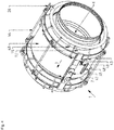
- Figs. 1 to 10 show an embodiment of an expansion joint 1 according to the present invention.
- the cross-sectional view as per Fig. 1 is taken along B-B in Fig. 3 .
- the expansion joint 1 is adapted for joining a first part of a pipe (not shown) to a second part of the pipe (not shown).
- the pipe and the expansion joint 1 can be parts of a plant for producing propylene from propane gas.
- the expansion joint 1 comprises an expanded wall 2 having a first wall part 3, e.g. made of stainless steel, and a second wall part 4, e.g. made of stainless steel.
- the first wall part 3 can be connected to the first part of the pipe, and the second wall part 4 can be connected to the second part of the pipe.
- the first wall part 3 can be an integral part of the first part of the pipe, and the second wall part 4 can be an integral part of the second part of the pipe.
- the first wall part 3 and the second wall 4 part are spaced apart from each other in an axial direction L of the expansion joint 1 by an axial gap.
- An expansion bellows 5 is welded onto the first wall part 3 with a weld seam a, and welded onto the second wall part 4 with a weld seam b, such that the axial gap between the first wall part 3 and the second wall part 4 is closed by the expansion bellows 5.
- the expansion bellows 5 is designed particularly in such a way that it enables to compensate relative movements of the parts of the pipe which are joint via the expansion joint 1.
- first wall part 3 and the second wall part 4 are connected flexibly by means of the expansion bellows 5, meaning that the first wall part 3 and the second wall part 4 are connected such that stresses caused by axial, angular or lateral movements between the first wall part 3 and the second wall part 4 can be compensated for, wherein said movements can occur due to high temperatures while hot propylene gas is led through a flow channel 6 within the expansion joint 1 during producing propylene from propane gas.
- An intended flow direction of propane gas through the flow channel 6 is indicated by arrow 7 in Fig. 2 and 4 .
- the flow channel 6 is limited in a radial direction r by an inner sleeve assembly 8.
- the inner sleeve assembly 8 can comprise a first metal part 8.1, e.g. made of stainless steel, and a second metal part 8.2, e.g. made of stainless steel.
- the expanded wall 2 and the inner sleeve assembly 8 limit at least one sealed chamber 9, 10 between each other, and the at least one sealed chamber 9, 10 is adapted to be filled and pressurised by a first gas or a first sort of gas, respectively.
- the first sort of gas may be nitrogen.
- the first metal part 8.1 is connected to the first wall part 3 such that the first metal part 8.1 and the first wall part 3 limit a first sealed chamber 9 between each other, wherein the first sealed chamber 9 is filled by the first sort of gas.
- the first sealed chamber 9 is adapted to be filled and pressurised by the first sort of gas.
- Fig. 7 a part of the inner sleeve assembly 8 and the first wall part 3 are shown in an enlarged view. As can be seen from the example shown by Fig.
- the inner sleeve assembly 8, in particular the first metal part 8.1 of the inner sleeve assembly 8, and the expanded wall 2, in particular the first wall part 3 of the expanded wall 2, can at least partly be formed integrally as a one piece element.
- the first metal part 8.1 of the inner sleeve assembly 8 can be connected to the first wall part 3 in a one-piece manner.
- Fig. 7 shows a weld preparation bevel to allow for sound welding over a full thickness of the joined parts (full penetration welds).
- the second metal part 8.2 is connected to the second wall part 4 such that the second metal part 8.2 and the second wall part 4 limit a second sealed chamber 10 between each other, wherein the second sealed chamber 10 is filled and by the first sort of gas.
- the second sealed chamber 10 is adapted to be filled and pressurised by the first sort of gas.
- the second wall part 4 and the second metal part 8.2 can be two separated elements.
- Fig. 8 shows a weld preparation bevel to allow for sound welding over a full thickness of the joined parts (full penetration welds).
- the first sealed chamber 9 and the second sealed chamber 10 can partly be filled with insulating material 11.
- the feature "sealed" especially can mean that said chambers 9 and 10 are built such that the first gas - by which the chambers 9 and 10 are pressurised - cannot leave the chambers 9 and 10.
- the first sealed chamber 9 and the second sealed chamber 10 can be designed substantially the same and can be arranged in mirror symmetry to each other as shown per Fig. 1 .
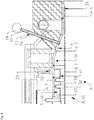
- the expansion joint 1 can further comprise first means 12 for sensing pressure and second means 13 for sensing pressure ( Figs. 2 to 5 ). Furthermore, the expansion joint one can comprise first gas supply means 14 and second gas supply means 15 ( Figs. 2 to 4 and 6 ).
- the second chamber 10 is shown in an enlarged view, wherein the insulating material 11 is not shown for purposes of simplicity.
- Fig. 5 shows the second means 13 for sensing pressure.
- the second means 13 for sensing pressure can comprise a connection channel 16, e.g. formed by a connection pipe 17.
- a first end of the connection channel 16 can be in a fluid connection with the second chamber 10.
- a second end of the connection channel 16 can be in a fluid connection with a pressure sensor 18 (shown in Fig. 5 ).
- the second means 13 for sensing pressure are adapted for measuring a second pressure within the second sealed chamber 10.
- the first means 12 for sensing pressure can be designed similarly and are adapted for measuring a first pressure within the first sealed chamber 9.
- Fig. 6 shows the second gas supply means 15 which can comprise a supply channel 19, e.g. formed by a supply pipe 20.
- a first end of the supply channel 19 can be in a fluid connection with the second chamber 10.
- a second end of the supply channel 19 can be in a fluid connection with a reservoir 21 (only shown schematic in Fig. 6 ) for storing the first gas in a pressurised manner.
- the fluid connection between the supply channel 19 and the reservoir 21 can be controlled such that first gas stored within the reservoir 21 can leave the reservoir 21 and fill as well as pressurise the second chamber 10.
- the second gas supply means 15 are adapted for filling and pressurising the second sealed chamber 10 with the first gas.
- the first gas supply means 14 can be designed similarly and are adapted for pressurising the first sealed chamber 9 with the first gas.
- a third chamber 22 is located between the first sealed chamber 9 and the second sealed chamber 10.
- the third chamber 22 can be limited by the first metal part 8.1 and the second metal part 8.2 of the inner sleeve assembly 8, the first wall part 3 and the second wall part 4 of the expanded wall 2 and the expansion bellows 5.
- the third chamber 22 can be separated from the first sealed chamber 9 by a first retaining ring assembly 23 on the one side (which is shown left in Fig. 1 ) and by a second retaining ring assembly 24 on the other side (which is shown right in Fig. 1 ), wherein both retaining ring assemblies 23 and 24 can comprise a monolithic part 50.
- Figs. 5 and 6 show the second retaining ring assembly 24 in an enlarged view, wherein the second retaining ring assembly 24 is arranged between the second wall part 4 of the expanded wall 2.
- the first retaining ring assembly 23 is designed and arranged within the first wall part 3 of the expansion bellows 5 similarly.
- the second wall part 4 can comprise a first section 4.1 with a gap which is filled by the second retaining ring assembly 24.
- the expansion bellows 5 can be welded onto one end (which is shown left in Figs. 5 and 6 ) of the first section 4.1 by the second weld seam b.
- the second wall part 4 can comprise a second section 4.2 and a third section 4.3.
- the third section 4.3 can be connected to the part of the pipe which is to be joined by the expansion joint 1.
- the diameter of the first section 4.1 is larger than the diameter of the third section 4.3.
- the second section 4.2 is inclined with regards to the first section 4.1 and the third section 4.3.
- the second section 4.2 connects the first section 4.1 to the third section 4.3.
- the first wall part 3 can comprise a first section 3.1 ( Fig. 10 ), a second and a third section similarly as can be seen from Figs. 1 and 10 .
- the third chamber 22 can be filled and pressurised with a second gas, e.g. with propane gas, such that an over pressure within the third chamber 22 is higher than a process pressure of the second gas flowing across the flow channel 6 of the expansion joint 1.
- the third chamber 22 is in fluid connection with the flow channel 6. Therefore, second gas from within the third chamber 22 can leave the third chamber 22 and enter the flow channel 6. Due to the higher pressure within the third chamber 22 compared to the flow channel 6, second gas from within the flow channel 6 is hindered to enter the third chamber 22.
- the third chamber 22 is filled with and pressurised by second gas, such that this second gas builds a barrier flow for second gas within the flow channel 6. By this, the third chamber 22 acts as an hyperbaric pressure chamber compared to the flow channel 6.
- a plurality of purge channels 25 can be in a fluid connection with the third chamber 22 on the one end and in a fluid connection with second gas supply connections 26 on the other ends.
- the purge channels 25 can be welded onto by fifth weld seams e and extend through the first retaining ring assembly 23 ( Fig. 10 ) and the second retaining ring assembly 24.
- the second gas supply connections 26 can be connected to a reservoir (not shown) for storing second gas in a pressurised manner.
- the fluid connection between the purge channels 25 and said reservoir can be controlled such that second gas stored within the reservoir can leave the reservoir and fill as well as pressurise the third chamber 22. In this way, the third chamber 22 can be pressurized with second gas.
- the first metal part 8.1 can comprise a first additional bellows 27 ( Fig. 10 ) and the second metal part 8.2 can comprise a second additional bellows 28 ( Figs. 5 and 6 ).
- the second additional bellows 28 is welded onto the second metal part 8.2 by a third weld seam c and onto the second retaining ring assembly 24 by a fourth weld seam d ( Fig. 6 ).
- the first additional bellows 27 is welded onto the first metal part 8.1 by a weld seam and onto the first retaining ring assembly 23 by a weld seam.
- the additional bellows 27 and 28 help to compensate for stresses that the first metal part 8.1 and the second metal part 8.2 (which can be relatively thin compared to the first wall part 3 and second wall part 4) are subjected to, in particular in areas of a first interior wall surface 29 of the inner sleeve 8 and a second interior wall surface 30 of the inner sleeve 8.
- the first metal part 8.1 can be bent 180° in a first bending area 31 and the second metal part 8.2 can be bent 180° in a second bending area 32, wherein the first bending area 31 of the first metal part 8.1 overlaps the second bending area 32 of the second metal part 8.2 such that pressurised gas from within the third chamber 22 can flow out of the third chamber 22 into the flow channel 6.
- a first end 34 of the first metal part 8.1 can be welded onto the first wall part 3 at a first connection position 35.
- a second end 35' of the first metal part 8.1, in particular its first additional bellows 27, can be connected to the first wall part 3, in particular to its first retaining ring assembly 23, at a second connection position 36 ( Fig. 10 ).
- a first portion 37 of the first metal part 8.1 between the first connection position 35 and the first bending area 31 provides the first interior wall surface 29 of the flow channel 6 ( Figs. 1 and 9 ).
- a first end 38 of the second metal part 8.2 can be connected to the second wall part 4 at a third connection position 39.
- a second end 40 of the second metal part 8.2, in particular its second additional bellows 28, can be connected to the second wall part 4, in particular to its second retaining ring assembly 24, at a fourth connection position 41.
- a first portion 42 of the second metal part 8.2 starting from the third connection position 39 and extending up to and including the second bending area 32 provides the second interior wall surface 30 of the flow channel 6.
- the expansion joint 1 can further comprise a removable cover 43 for protection during transportation and against environmental influences.
- an outer insulation 44 can be provided which surrounds the expanded wall 2.
- the expansion joint 1 can further comprise an inspection hole 45.
- the expansion joint 1 can further comprise tie rods 46 as a transportation safety guard, wherein the tie rods 46 have to be removed before start up.
- axial movement indicators 47 can be provided as well as an interply monitoring connection 48 and a nameplate 49.
- the bellows 5 can be composed of several thin metal layers, so called ,plies'.
- the interply monitoring connection 48 enables an interply monitoring in order to detect eventual leaks in one of the plies, wherein such leaks may not be detectable from the outside. Additional weld seams are indicated with hexagons within the drawings.
Description
- The invention relates to an expansion joint for joining two adjacent parts of a pipe. In particular, said pipe can be part of a plant for producing propylene from propane gas, a process which is especially known under the Trademark CATOFIN®.
- An expansion joint for two adjacent parts of a pipe is an element which joins or connects the parts of the pipe in a flexible manner. In particular, an expansion joint can safely absorb heat-induced expansion and contraction of the adjacent parts of the pipe, e.g. to absorb vibration, to hold the parts together, or to allow a movement of the parts of the pipe due to thermal or mechanical stresses which can be compensated for by means of the expansion joint. Expansion joints are used e.g. in plants in which propylene can be produced from propane gas in a catalyst process by means of a dehydrogenation, wherein an amount of hydrogen is reduced in the propane. This process is an advantageous alternative to known production methods, which usually involve a cracking of crude oil in refineries. Typically, there can be more than 20 expansion joints in such a plant for producing propylene from propane gas, in particular about 10 expansion joints in an inlet region and about 10 expansion joints in an outlet region. The expansion joints are critical elements of the plant and must fulfil their functions at very high temperatures, extreme flow velocities, and large cyclic movements. The two most common types of expansion joints in the plant are arranged in areas of an inlet header and an outlet header of the plant.
- Expansion joints are known, which comprise an expansion bellows and an expanded wall designed to protect the expansion bellows from corrosion and damage due to overheating. The expansion bellows is welded onto the expanded wall, e.g. of an inlet pipe. An inner sleeve creates a chamber that separates the process fluid from the expanded wall and the bellows. Typically, this chamber is separated into two smaller chambers on either side of the expanded wall, wherein the two smaller chambers are filled with an insulation material. Due to differing thermal expansion coefficients of the materials involved, the two ends of the inner sleeve cannot be sealed. As a result, an opening is created, which allows process fluid to escape into the chamber. This can lead to an increase of temperature and creates a risk of coking. To solve this problem, solutions are known, according to which a channel that is created in a middle area between the insulation material chambers is constantly flushed with fresh propane gas.
- The fresh propane gas can enter a main flow channel for the process gas via the opening between the two ends of the inner sleeve. This can have a potential detrimental effect on the temperature of the process fluid and on the yield of producing propylene from the propane gas, due to the fact that the flushing fluid has to be at a lower temperature than the process fluid to provide cooling at the bellows. Furthermore, in the area of the expanded wall and the inner sleeve coking can occur due to hydrocarbon material stagnating in high-temperature dead zones that are created within the inner sleeve and the expanded wall. In particular, at temperatures above 480°C some olefins and di-olefins can be produced. At these temperatures and with sufficient residence time the olefins and di-olefins can convert to coke.
- Expansion joints for joining two adjacent parts of a pipe are disclosed in
FR 2 124 846 A5EP 0 376 839 A1 ,US 2015/084328 A1 orEP 0 028 742 A1 . - It is an object of the present invention to provide an expansion joint for joining two adjacent parts of a pipe, wherein a bellows of the expansion joint is better protected from higher temperatures of a fluid flowing across the expansion joint and wherein coking is avoided.
- The problem is solved by the subject matter according to the independent claim.
- The dependent claims, the following description and the drawings show preferred embodiments of the invention.
- According to a first aspect of the invention, an expansion joint for joining two adjacent parts of a pipe. e.g. made of stainless steel, is provided. In particular, the two adjacent parts of the pipe can be part of a plant for producing propylene from propane gas, a process which is especially known under the Trademark CATOFIN®. The expansion joint comprises an expansion bellows, e.g. made of stainless steel, an expanded wall and an inner sleeve assembly.
- The expanded wall comprises a first wall part, e.g. made of stainless steel, and a second wall part, e.g. made of stainless steel. The first wall part and the second wall part are spaced apart from each other axially by an axial gap. In particular, a first end face of the first wall part can face a second end face of the second wall part, wherein said first end face and said second end face are spaced apart from each other by the axial gap. In this context, the feature "expanded wall" particularly can mean that the wall is expanded in a radial direction compared to the two parts of the pipe, respectively, which can be joined by the expansion joint. In other words, the diameter of the expanded wall can be larger than the diameters of the two parts of the pipe of the pipe system which can be joined by the expansion joint.
- The first wall part of the expanded wall can be mechanically connected to one of the two adjacent parts of the pipe, and the second wall part of the expanded wall can be mechanically connected to the other one of the two adjacent parts of the pipe. Alternatively, the first wall part of the expanded wall can be a part of one of the two adjacent parts of the pipe, meaning that the first wall part and one of the two adjacent parts of the pipe are connected to each other in a one-piece manner. Similarly, the second wall part of the expanded wall can be a part of the other one of the two adjacent parts of the pipe, meaning that the second wall part and the other one of the two adjacent parts of the pipe are connected to each other in a one-piece manner.
- The expansion bellows is connected to the first wall part, in particular welded onto the first wall part, and connected to the second wall part, in particular welded onto the second wall part, such that the axial gap between the first wall part and the second wall part is closed and such that the first wall part and the second wall part are connected flexibly. in this context, the feature "connected flexibly" can especially mean that the first wall part and the second wall part are connected such that stresses caused by axial, angular and lateral movements between the first wall part and the second wall part can be compensated for, wherein said stresses can occur due to high temperatures (e.g. 650° C) and high pressures (e.g. 2.9 bar) of propane gas flowing across the expansion joint during producing propylene from propane gas. Similar to the first wall part and the second wall part, the expansion bellows can be designed in an expanded manner with regards to a radial direction compared to the two parts of the pipe, which can be joined by the expansion joint. In other words, the diameter of the expansion bellows can be larger than the diameters of the two parts of the pipe which can be joined by the expansion joint.
- The expanded wall and the inner sleeve assembly limit at least one sealed chamber between each other, and the at least one sealed chamber is filled by a first gas. In particular, the sealed chamber can be adapted to be filled and to be pressurized by the first gas. In other words, the expansion joint according to the first aspect of the invention, comprises a sealed chamber arrangement, in particular a pressurized sealed chamber arrangement, which enables that the expansion bellows is protected from a high temperature of a process fluid flowing across a flow channel within the expansion joint.
- The at least one sealed chamber helps to eliminate the presence of hydrocarbon in an area of the expansion bellows, thus helping to eliminate the potential for damage due to coke formation. The at least one sealed chamber can extend across the whole circumference of the expansion joint, meaning that the at least one sealed chamber extends 360° in a circumferential direction. The expansion joint according to the first aspect of the invention can particularly be used both in an inlet section as well as in an outlet section of a plant for producing propylene from propane gas, wherein a same expansion joint can be employed albeit at different sizes.
- According to an embodiment, the inner sleeve assembly comprises a first metal part, e.g. made of stainless steel, and a second metal part, e.g. made of stainless steel. The first metal part is connected to the first wall part, in particular welded onto the first wall part, such that the first metal part and the first wall part limit a first sealed chamber between each other. Similarly, the second metal part can be connected to the second wall part, in particular can be welded onto the second wall part, such that the second metal part and the second wall part limit a second sealed chamber between each other. The first sealed chamber and the second sealed chamber are filled by the first gas. In particular, the first sealed chamber and the second sealed chamber are adapted to be filled and to be pressurized by the first gas. If the first sealed chamber and the second sealed chamber are filled, and preferably also pressurised by the first gas, they are able to balance stresses during temperature cycles of a process gas flowing across the pipes and the expansion joint.
- The at least one sealed chamber, in particular the first sealed chamber and the second sealed chamber, can be filled with insulating material. This helps to further protect the expansion bellows from high temperatures within the flow channel.
- The expansion joint of the invention is characterized in that the inner sleeve assembly, in particular its first metal part and its second metal part, the expanded wall, in particular its first wall part and its second wall part, and the expansion bellows limit a third chamber between each other. The third chamber is adapted to be filled and pressurized with a second gas, such that an over pressure within the third chamber is higher than a process pressure of the second gas within a flow channel within the expansion joint. The flow channel is limited by the inner sleeve assembly, in particular a first interior wall surface provided by the first metal part and a second interior wall surface provided by the second metal part.
- In particular, the third chamber can be located between the first sealed chamber and the second sealed chamber in an axial direction of the expansion joint. The third chamber is in fluid connection with the flow channel which enables second gas from within the third chamber to leave the third chamber and to enter the flow channel. Due to the higher pressure within the third chamber compared to the flow channel, second gas from within the flow channel is hindered to enter the third chamber.
- In other words, the third chamber can be filled with and pressurized by the second gas, such that the second gas builds a barrier flow for the gas within the flow channel and that the third chamber acts as an hyperbaric pressure chamber compared to the flow channel. This helps to keep the hot gas within the flow channel away from the expansion bellows. Also, this helps to prevent the occurring of carbonization within the third chamber, which could lead to an undesired clogging within the third chamber. According to a preferred embodiment, the second gas is the same sort of gas that flows through the flow channel, i.e. the process gas, in particular propane gas.
- According to another embodiment, the first metal part comprises a first additional bellows and the second metal part comprises a second additional bellows. The first additional bellows and the second additional bellows help to compensate for stresses that the pipes, the first metal part and the second metal part (which can be relatively thin compared to the pipes) are subjected to, in particular in areas of the first interior wall surface and the second interior wall surface.
- According to another embodiment, the first wall part comprises a first retaining ring assembly and the second wall part comprises a second retaining ring assembly. The first retaining ring assembly separates the first sealed chamber from the third chamber and the second retaining ring assembly separates the second sealed chamber from the third chamber. Furthermore, the first retaining ring assembly and the second retaining ring assembly can comprise monolithic parts. The inventors found out and verified by simulation that these monolithic parts enable that the first metal part and the second metal part withstand high temperature stresses which occur during process cycles within a plant for producing propylene from propane gas. At the same time, simulations showed that temperatures reaching the expansion bellows do not exceed a design temperature of the material of the expansion bellows.
- Furthermore, the first metal part can be bent 180° in a first bending area and the second metal part can be bent 180° in a second bending area, wherein the first bending area of the first metal part overlaps the second bending area of the second metal part such that pressurised second gas from within the third chamber can flow out of the third chamber into the flow channel. In particular, there can be a radial gap between the first bending area of the first metal part and the second bending area of the second metal part such that a connection channel for the second gas is built that allows second gas from within the third chamber to exit the third chamber and enter the flow channel via said connection channel. Due to the 180° bending, the first and second bending area are designed in a particular strength manner and can resist high stresses.
- According to another embodiment, a first end of the first metal part is connected to, in particular welded onto the first wall part at a first connection position, a second end of the first metal part is connected to, in particular welded onto the first wall part at a second connection position, and a first portion of the first metal part between the first connection position and the first bending area provides a first interior wall surface of the flow channel. Similarly, according to this embodiment, a first end of the second metal part is connected to, in particular welded onto the second wall part at a third connection position, a second end of the second metal part is connected to, in particular welded onto the second wall part at a fourth connection position, and a first portion of the second metal part between the third connection position and the second bending area provides a second interior wall surface of the flow channel.
- According to this embodiment, the inner sleeve of the expansion joint is formed by the first metal part, in particular by its first portion between the first connection position and the first bending area, and the second metal part, in particular by its first portion between the third connection position and the second bending area. Therefore, the first metal part serves to build the first sealed chamber as well as a part of the inner sleeve assembly, and the second metal part serves to build the second sealed chamber as well as another part of the inner sleeve assembly. Due to their aforesaid double functions, there is no need for an additional element which forms the inner sleeve assembly. Thus this embodiment helps to save parts, weight, manufacturing affords and costs.
- The expansion joint can further comprise first means for sensing pressure and second means for sensing pressure, wherein the first means for sensing pressure are adapted for measuring a first pressure, in particular a first pressure value, within the first sealed chamber, and wherein the second means for sensing pressure are adapted for measuring a second pressure, in particular a second pressure value, within the second sealed chamber. In case a potential leak occurs in the first sealed chamber or the second sealed chamber, such a leak can be monitored by means of the first or the second means for sensing pressure, respectively, wherein a loss of pressure within the respective sealed chamber can indicate the leak. Said loss of pressure can be determined e.g. by comparing a pressure value sensed at a first moment of time with a second pressure value sensed at a second moment of time, wherein the second moment of time lies before the first moment of time. Furthermore the first means for sensing pressure and the second means for sensing pressure can be adapted for generating data representing the measured pressure values, wherein the generated data can be transmitted e.g. to an electronic control unit for controlling a filling and pressurizing of the first sealed chamber and/or the second sealed chamber with the first gas.
- Furthermore, the expansion joint can comprise first gas supply means and second gas supply means, wherein the first gas supply means are adapted for filling and preferably also for pressurising the first sealed chamber with the first gas, and wherein the second gas supply means are adapted for filling and preferably also for pressurising the second sealed chamber with the first gas.
- In particular, if the first means for sensing pressure have measured a loss of pressure within the first sealed chamber, the first gas supply means can be adapted for refilling and re-pressuring the first sealed chamber with a sufficient amount of the first gas, such that the loss of pressure is compensated for. During such a refilling and a re-pressuring, the first means for sensing pressure can be adapted for sensing, preferably in a continuous manner, the pressure within the first sealed chamber. Preferably, an electrical control unit can be adapted for automatically controlling said refilling and re-pressuring. During such a controlling, especially the pressure value within the first sealed chamber measured by the first means for sensing pressure can be used as an input for the controlling. Furthermore, after said refilling and re-pressuring has been conducted, the first means for sensing pressure can sense the pressure within the first chamber again, such that a potential leak in the first chamber is searched for again.
- Similarly, if the second means for sensing pressure have measured a loss of pressure within the second sealed chamber, the second gas supply means can be adapted for refilling and re-pressuring the second sealed chamber with a sufficient amount of the first gas, such that the loss of pressure is compensated for. During such a refilling and a re-pressuring, the second means for sensing pressure can be adapted for sensing, preferably in a continuous manner, the pressure within the second sealed chamber. Preferably, an electrical control unit can be adapted for automatically controlling said refilling and re-pressuring. During such a controlling, especially the pressure value within the second sealed chamber measured by the second means for sensing pressure can be used as an input for the controlling. Furthermore, after said refilling and re-pressuring has been conducted, the second means for sensing pressure can sense the pressure within the second chamber again, such that a potential leak in the second chamber is searched for again.
- According to another embodiment, the expansion joint further comprises third gas supply means, wherein the third gas supply means are adapted for filling and pressurising the third chamber up to the over pressure with the second gas. In particular, the third gas supply means can comprise at least one purge channel in fluid connection with the third chamber and a reservoir for storing the second gas in a pressurized manner, wherein second gas stored within the reservoir can enter the third chamber via the at least one purge channel for filling and pressurising the third chamber up to the over pressure with the second gas.
- Preferably, the first gas is nitrogen. Also preferably, the second gas is propane gas.
- According to still another embodiment, the inner sleeve assembly, and the expanded wall can at least partly be formed integrally as a one piece element. This helps to increase the stability of the expanded wall and the inner sleeve assembly and particularly increases the tightness of the at least one sealed chamber due to the advantage that especially less weld seams unnecessary to connect the inner sleeve assembly to the expanded wall.
- According to a second aspect of the invention, a plant for producing propylene from propane gas is provided. The plant comprises a first part of a pipe, a second part of the pipe and an expansion joint according to the first aspect of the invention, wherein the first part of the pipe is joined to the second part of the pipe by means of the expansion joint.
- These and other aspects of the invention will be apparent from and elucidated with reference to the embodiments described hereinafter.
- In the following description exemplary embodiments of the invention are explained with reference to the accompanying drawing in which
- Fig. 1
- shows a cross-sectional view of an expansion joint in accordance with an embodiment of the invention,
- Fig. 2
- shows a first side view of the expansion joint as per
Fig. 1 , - Fig. 3
- shows a second side view of the expansion joint as per
Fig. 1 , - Fig. 4
- shows a perspective view of the expansion joint as per
Fig. 1 , - Fig. 5
- shows a cross-sectional view of the expansion joint as per
Fig. 1 taken along F-F inFig. 3 , - Fig. 6
- shows a cross-sectional view of the expansion joint as per
Fig. 1 taken along G-G inFig. 3 , - Fig. 7
- shows an enlarged view of detail C of the expansion joint as per
Fig. 1 , - Fig. 8
- shows an enlarged view of detail D of the expansion joint as per
Fig. 1 , - Fig. 9
- shows an enlarged view of detail E of the expansion joint as per
Fig. 1 , and - Fig. 10
- shows an enlarged view of detail H of the expansion joint as per
Fig. 1 , -
Figs. 1 to 10 show an embodiment of anexpansion joint 1 according to the present invention. The cross-sectional view as perFig. 1 is taken along B-B inFig. 3 . Theexpansion joint 1 is adapted for joining a first part of a pipe (not shown) to a second part of the pipe (not shown). In particular, the pipe and theexpansion joint 1 can be parts of a plant for producing propylene from propane gas. - The
expansion joint 1 comprises an expandedwall 2 having afirst wall part 3, e.g. made of stainless steel, and asecond wall part 4, e.g. made of stainless steel. Thefirst wall part 3 can be connected to the first part of the pipe, and thesecond wall part 4 can be connected to the second part of the pipe. Alternatively, thefirst wall part 3 can be an integral part of the first part of the pipe, and thesecond wall part 4 can be an integral part of the second part of the pipe. - The
first wall part 3 and thesecond wall 4 part are spaced apart from each other in an axial direction L of theexpansion joint 1 by an axial gap. An expansion bellows 5 is welded onto thefirst wall part 3 with a weld seam a, and welded onto thesecond wall part 4 with a weld seam b, such that the axial gap between thefirst wall part 3 and thesecond wall part 4 is closed by the expansion bellows 5. The expansion bellows 5 is designed particularly in such a way that it enables to compensate relative movements of the parts of the pipe which are joint via theexpansion joint 1. - In other words, the
first wall part 3 and thesecond wall part 4 are connected flexibly by means of the expansion bellows 5, meaning that thefirst wall part 3 and thesecond wall part 4 are connected such that stresses caused by axial, angular or lateral movements between thefirst wall part 3 and thesecond wall part 4 can be compensated for, wherein said movements can occur due to high temperatures while hot propylene gas is led through aflow channel 6 within theexpansion joint 1 during producing propylene from propane gas. An intended flow direction of propane gas through theflow channel 6 is indicated byarrow 7 inFig. 2 and4 . Theflow channel 6 is limited in a radial direction r by aninner sleeve assembly 8. - The
inner sleeve assembly 8 can comprise a first metal part 8.1, e.g. made of stainless steel, and a second metal part 8.2, e.g. made of stainless steel. The expandedwall 2 and theinner sleeve assembly 8 limit at least one sealedchamber chamber - In the shown example, the first metal part 8.1 is connected to the
first wall part 3 such that the first metal part 8.1 and thefirst wall part 3 limit a first sealedchamber 9 between each other, wherein the first sealedchamber 9 is filled by the first sort of gas. Preferably, the first sealedchamber 9 is adapted to be filled and pressurised by the first sort of gas. Particularly referring toFig. 7 , a part of theinner sleeve assembly 8 and thefirst wall part 3 are shown in an enlarged view. As can be seen from the example shown byFig. 7 , theinner sleeve assembly 8, in particular the first metal part 8.1 of theinner sleeve assembly 8, and the expandedwall 2, in particular thefirst wall part 3 of the expandedwall 2, can at least partly be formed integrally as a one piece element. In other words, especially the first metal part 8.1 of theinner sleeve assembly 8 can be connected to thefirst wall part 3 in a one-piece manner. Furthermore,Fig. 7 shows a weld preparation bevel to allow for sound welding over a full thickness of the joined parts (full penetration welds). - Similarly, the second metal part 8.2 is connected to the
second wall part 4 such that the second metal part 8.2 and thesecond wall part 4 limit a second sealedchamber 10 between each other, wherein the second sealedchamber 10 is filled and by the first sort of gas. Preferably, the second sealedchamber 10 is adapted to be filled and pressurised by the first sort of gas. Particularly referring toFig. 8 , thesecond wall part 4 and the second metal part 8.2 can be two separated elements. Furthermore,Fig. 8 shows a weld preparation bevel to allow for sound welding over a full thickness of the joined parts (full penetration welds). - As shown in
Fig. 1 , the first sealedchamber 9 and the second sealedchamber 10 can partly be filled with insulating material 11. In the context of the first sealedchamber 9 and the second sealedchamber 10, the feature "sealed" especially can mean that saidchambers chambers chambers chamber 9 and the second sealedchamber 10 can be designed substantially the same and can be arranged in mirror symmetry to each other as shown perFig. 1 . - The
expansion joint 1 can further comprise first means 12 for sensing pressure and second means 13 for sensing pressure (Figs. 2 to 5 ). Furthermore, the expansion joint one can comprise first gas supply means 14 and second gas supply means 15 (Figs. 2 to 4 and6 ). - Particularly referring to
Figs. 5 and6 , thesecond chamber 10 is shown in an enlarged view, wherein the insulating material 11 is not shown for purposes of simplicity. -
Fig. 5 shows the second means 13 for sensing pressure. According to the example shown byFig. 5 , the second means 13 for sensing pressure can comprise aconnection channel 16, e.g. formed by aconnection pipe 17. A first end of theconnection channel 16 can be in a fluid connection with thesecond chamber 10. A second end of theconnection channel 16 can be in a fluid connection with a pressure sensor 18 (shown inFig. 5 ). The second means 13 for sensing pressure are adapted for measuring a second pressure within the second sealedchamber 10. The first means 12 for sensing pressure can be designed similarly and are adapted for measuring a first pressure within the first sealedchamber 9. -
Fig. 6 shows the second gas supply means 15 which can comprise asupply channel 19, e.g. formed by asupply pipe 20. A first end of thesupply channel 19 can be in a fluid connection with thesecond chamber 10. A second end of thesupply channel 19 can be in a fluid connection with a reservoir 21 (only shown schematic inFig. 6 ) for storing the first gas in a pressurised manner. The fluid connection between thesupply channel 19 and thereservoir 21 can be controlled such that first gas stored within thereservoir 21 can leave thereservoir 21 and fill as well as pressurise thesecond chamber 10. In this way, the second gas supply means 15 are adapted for filling and pressurising the second sealedchamber 10 with the first gas. The first gas supply means 14 can be designed similarly and are adapted for pressurising the first sealedchamber 9 with the first gas. - A
third chamber 22 is located between the first sealedchamber 9 and the second sealedchamber 10. Thethird chamber 22 can be limited by the first metal part 8.1 and the second metal part 8.2 of theinner sleeve assembly 8, thefirst wall part 3 and thesecond wall part 4 of the expandedwall 2 and the expansion bellows 5. - As shown by
Fig. 1 , thethird chamber 22 can be separated from the first sealedchamber 9 by a first retaining ring assembly 23 on the one side (which is shown left inFig. 1 ) and by a secondretaining ring assembly 24 on the other side (which is shown right inFig. 1 ), wherein both retainingring assemblies 23 and 24 can comprise amonolithic part 50.Figs. 5 and6 show the secondretaining ring assembly 24 in an enlarged view, wherein the secondretaining ring assembly 24 is arranged between thesecond wall part 4 of the expandedwall 2. The first retaining ring assembly 23 is designed and arranged within thefirst wall part 3 of the expansion bellows 5 similarly. - In particular, the
second wall part 4 can comprise a first section 4.1 with a gap which is filled by the secondretaining ring assembly 24. The expansion bellows 5 can be welded onto one end (which is shown left inFigs. 5 and6 ) of the first section 4.1 by the second weld seam b. Furthermore, thesecond wall part 4 can comprise a second section 4.2 and a third section 4.3. The third section 4.3 can be connected to the part of the pipe which is to be joined by theexpansion joint 1. The diameter of the first section 4.1 is larger than the diameter of the third section 4.3. The second section 4.2 is inclined with regards to the first section 4.1 and the third section 4.3. The second section 4.2 connects the first section 4.1 to the third section 4.3. Thefirst wall part 3 can comprise a first section 3.1 (Fig. 10 ), a second and a third section similarly as can be seen fromFigs. 1 and10 . - The
third chamber 22 can be filled and pressurised with a second gas, e.g. with propane gas, such that an over pressure within thethird chamber 22 is higher than a process pressure of the second gas flowing across theflow channel 6 of theexpansion joint 1. Thethird chamber 22 is in fluid connection with theflow channel 6. Therefore, second gas from within thethird chamber 22 can leave thethird chamber 22 and enter theflow channel 6. Due to the higher pressure within thethird chamber 22 compared to theflow channel 6, second gas from within theflow channel 6 is hindered to enter thethird chamber 22. In other words, thethird chamber 22 is filled with and pressurised by second gas, such that this second gas builds a barrier flow for second gas within theflow channel 6. By this, thethird chamber 22 acts as an hyperbaric pressure chamber compared to theflow channel 6. - A plurality of
purge channels 25 can be in a fluid connection with thethird chamber 22 on the one end and in a fluid connection with secondgas supply connections 26 on the other ends. Thepurge channels 25 can be welded onto by fifth weld seams e and extend through the first retaining ring assembly 23 (Fig. 10 ) and the secondretaining ring assembly 24. The secondgas supply connections 26 can be connected to a reservoir (not shown) for storing second gas in a pressurised manner. The fluid connection between thepurge channels 25 and said reservoir can be controlled such that second gas stored within the reservoir can leave the reservoir and fill as well as pressurise thethird chamber 22. In this way, thethird chamber 22 can be pressurized with second gas. - The first metal part 8.1 can comprise a first additional bellows 27 (
Fig. 10 ) and the second metal part 8.2 can comprise a second additional bellows 28 (Figs. 5 and6 ). The secondadditional bellows 28 is welded onto the second metal part 8.2 by a third weld seam c and onto the secondretaining ring assembly 24 by a fourth weld seam d (Fig. 6 ). Similarly, the firstadditional bellows 27 is welded onto the first metal part 8.1 by a weld seam and onto the first retaining ring assembly 23 by a weld seam. The additional bellows 27 and 28 help to compensate for stresses that the first metal part 8.1 and the second metal part 8.2 (which can be relatively thin compared to thefirst wall part 3 and second wall part 4) are subjected to, in particular in areas of a first interior wall surface 29 of theinner sleeve 8 and a secondinterior wall surface 30 of theinner sleeve 8. - As can best be seen in
Fig. 9 , the first metal part 8.1 can be bent 180° in a first bending area 31 and the second metal part 8.2 can be bent 180° in asecond bending area 32, wherein the first bending area 31 of the first metal part 8.1 overlaps thesecond bending area 32 of the second metal part 8.2 such that pressurised gas from within thethird chamber 22 can flow out of thethird chamber 22 into theflow channel 6. In particular, there can be a radial gap between the first bending area 31 of thefirst wall part 3 and thesecond bending area 32 of thesecond wall part 4 such that aconnection channel 33 for the gas is built that allows gas from within thethird chamber 22 to exit thethird chamber 22 and to enter theflow channel 6 via saidconnection channel 33. - As can be seen from
Fig. 1 afirst end 34 of the first metal part 8.1 can be welded onto thefirst wall part 3 at afirst connection position 35. A second end 35' of the first metal part 8.1, in particular its firstadditional bellows 27, can be connected to thefirst wall part 3, in particular to its first retaining ring assembly 23, at a second connection position 36 (Fig. 10 ). Afirst portion 37 of the first metal part 8.1 between thefirst connection position 35 and the first bending area 31 provides the first interior wall surface 29 of the flow channel 6 (Figs. 1 and9 ). - Similarly, as can be seen e.g. from
Figs. 5 ,6 and8 , afirst end 38 of the second metal part 8.2 can be connected to thesecond wall part 4 at athird connection position 39. A second end 40 of the second metal part 8.2, in particular its secondadditional bellows 28, can be connected to thesecond wall part 4, in particular to its secondretaining ring assembly 24, at afourth connection position 41. A first portion 42 of the second metal part 8.2 starting from thethird connection position 39 and extending up to and including thesecond bending area 32 provides the secondinterior wall surface 30 of theflow channel 6. - Particularly referring to
Fig. 1 , theexpansion joint 1 can further comprise aremovable cover 43 for protection during transportation and against environmental influences. Also, an outer insulation 44 can be provided which surrounds the expandedwall 2. Particularly referring toFig. 2 , theexpansion joint 1 can further comprise aninspection hole 45. Particularly referring toFig. 4 , theexpansion joint 1 can further comprisetie rods 46 as a transportation safety guard, wherein thetie rods 46 have to be removed before start up. Also,axial movement indicators 47 can be provided as well as aninterply monitoring connection 48 and anameplate 49. Thebellows 5 can be composed of several thin metal layers, so called ,plies'. Theinterply monitoring connection 48 enables an interply monitoring in order to detect eventual leaks in one of the plies, wherein such leaks may not be detectable from the outside. Additional weld seams are indicated with hexagons within the drawings. -
- a
- first weld seam
- b
- second weld seam
- c
- third weld seam
- d
- fourth weld seam
- e
- fifth weld seam
- L
- axial direction
- r
- radial direction
- 1
- expansion joint
- 2
- expanded wall
- 3
- first wall part
- 3.1
- first section of the first wall part
- 4
- second wall part
- 4.1
- first section of the second wall part
- 4.2
- second section of the second wall part
- 4.3
- third section of the second wall part
- 5
- expansion bellows
- 6
- flow channel
- 7
- arrow flow direction
- 8
- inner sleeve assembly
- 8.1
- first metal part
- 8.2
- second metal part
- 9
- first sealed chamber
- 10
- second sealed chamber
- 11
- insulation material
- 12
- first means for sensing pressure
- 13
- second means for sensing pressure
- 14
- first gas supply means
- 15
- second gas supply means
- 16
- connection channel
- 17
- connection pipe
- 18
- pressure sensor
- 19
- supply channel
- 20
- supply pipe
- 21
- reservoir for storing the first gas
- 22
- third chamber
- 23
- first retaining ring assembly
- 24
- second retaining ring assembly
- 25
- purge channel
- 26
- propane gas supply connections
- 27
- first additional bellows
- 28
- second additional bellows
- 29
- first interior wall surface
- 30
- second interior wall surface
- 31
- first bending area
- 32
- second bending area
- 33
- connection channel
- 34
- first end of the first metal part
- 35
- first connection position
- 35'
- second end of the first metal part
- 36
- second connection position
- 37
- first portion of the first metal part
- 38
- first end of the second metal part
- 39
- third connection position
- 40
- second end of the second metal part
- 41
- fourth connection position
- 42
- first portion of the second metal part
- 43
- removable cover
- 44
- outer insulation
- 45
- inspection hole
- 46
- tie rod
- 47
- axial movement indicator
- 48
- interply monitoring connection
- 49
- nameplate
- 50
- monolithic part
Claims (14)
- An expansion joint (1) for joining two adjacent parts of a pipe, the expansion joint (1) comprising:- an expansion bellows (5),- an expanded wall (2) and- an inner sleeve assembly (8),
wherein- the expanded wall (2) comprises a first wall part (3) and a second wall part (4), wherein the first wall part (3) and the second wall part (4) are spaced apart from each other axially by an axial gap,- the expansion bellows (5) is connected to the first wall part (3) and to the second wall part (4) such that the axial gap between the first wall part (3) and the second wall part (4) is closed and such that the first wall part (3) and the second wall part (4) are connected flexibly,- the expanded wall (2) and the inner sleeve assembly (8) limit at least one sealed chamber (9, 10) between each other, and- the at least one sealed chamber (9, 10) is filled by a first gas,
characterized in that- the inner sleeve assembly (8), the expanded wall (2) and the expansion bellows (5) limit a third chamber (22) between each other,- the third chamber (22) is in fluid connection with a flow channel (6), wherein the flow channel (6) is limited by the inner sleeve assembly (8), and- the third chamber (22) is adapted to be filled and pressurized with a second gas, such that an over pressure within the third chamber (22) is higher than a process pressure of the second gas within the flow channel (6) within the expansion joint (1). - The expansion joint (1) according to claim 1, wherein the inner sleeve assembly (8) comprises a first metal part (8.1) and a second metal part (8.2), wherein- the first metal part (8.1) is connected to the first wall part (3) such that the first metal part (8.1) and the first wall part (3) limit a first sealed chamber (9) between each other,- the second metal part (8.2) is connected to the second wall part (4) such that the second metal part (8.2) and the second wall part (4) limit a second sealed chamber (10) between each other, and- the first sealed chamber (9) and the second sealed chamber (10) are adapted to be filled and pressurised by the first gas.
- The expansion joint (1) according to claim 1 or 2, wherein the at least one sealed chamber (9, 10) is filled with insulating material (11).
- The expansion joint (1) according to one of the claims 2 to 3yes , wherein- the first metal part (8.1) comprises a first additional bellows (27) and- the second metal part (8.2) comprises a second additional bellows (28).
- The expansion joint (1) according to any one of the preceding claims, wherein- the first wall part (3) comprises a first retaining ring assembly (23),- the second wall part (4) comprises a second retaining ring assembly (24),- the first retaining ring assembly (23) separates the first sealed chamber (9) from the third chamber (22), and- the second retaining ring assembly (24) separates the second sealed chamber (10) from the third chamber (22).
- The expansion joint (1) according to one of the claims 2 to 5, wherein- the first metal part (8.1) is bent 180° in a first bending area (31),- the second metal part (8.2) is bent 180° in a second bending area (32), and- the first bending area (31) of the first metal part (8.1) overlaps the second bending area (32) of the second metal part (8.2) such that pressurised second gas from within the third chamber (22) can flow out of the third chamber (22) into the flow channel (6).
- The expansion joint (1) according to claim 6, wherein- a first end (34) of the first metal part (8.1) is connected to the first wall part (3) at a first connection position (35),- a second end (35') of the first metal part (8.1) is connected to the first wall part (3) at a second connection position (36),- a first portion (37) of the first metal part (8.1) between the first connection position (35) and the first bending area (31) provides a first interior wall surface (29) of the flow channel (6),- a first end (38) of the second metal part (8.2) is connected to the second wall part (4) at a third connection position (39),- a second end (40) of the second metal part (8.2) is connected to the second wall part (4) at a fourth connection position (41), and- a first portion (42) of the second metal part (8.2) between the third connection position (39) and the second bending area (32) provides a second interior wall surface (30) of the flow channel (6).
- The expansion joint (1) according to one of the claims 2 to 7, the expansion joint (1) further comprising first means (12) for sensing pressure and second means (13) for sensing pressure, wherein the first means (12) for sensing pressure are adapted for measuring a first pressure within the first sealed chamber (9), and wherein the second means (13) for sensing pressure are adapted for measuring a second pressure within the second sealed chamber (10).
- The expansion joint (1) according to one of the claims 2 to 8, wherein the expansion joint (1) further comprises first gas supply means (14) and second gas supply means (15), wherein the first gas supply means (14) are adapted for filling the first sealed chamber (9) with the first gas, and wherein the second gas supply means (15) are adapted for filling the second sealed chamber (10) with the first gas.
- The expansion joint (1) according to one of the preceding claims, the expansion joint (1) further comprising third gas supply means (25, 26), wherein the third gas supply means (25, 26) are adapted for filling and pressurising the third chamber (22) up to the over pressure with the second gas.
- The expansion joint (1) according to one of the preceding claims, wherein the first gas is nitrogen.
- The expansion joint (1) according to one of the preceding claims, wherein the second gas is propane gas.
- The expansion joint (1) according to one of the preceding claims, wherein the inner sleeve assembly (8), and the expanded wall (2) can at least partly be formed integrally as a one piece element.
- Plant for producing propylene from propane gas, the plant comprising a first part of a pipe, a second part of the pipe and an expansion joint (1) according to one of the preceding claims, wherein the first part of the pipe is joined to the second part of the pipe by means of the expansion joint (1).
Priority Applications (8)
| Application Number | Priority Date | Filing Date | Title |
|---|---|---|---|
| PL17175959T PL3415802T3 (en) | 2017-06-14 | 2017-06-14 | Expansion joint |
| EP17175959.0A EP3415802B1 (en) | 2017-06-14 | 2017-06-14 | Expansion joint |
| US16/619,276 US11402048B2 (en) | 2017-06-14 | 2018-06-11 | Expansion joint |
| CA3064013A CA3064013C (en) | 2017-06-14 | 2018-06-11 | Expansion joint |
| CN201880037884.4A CN110741197A (en) | 2017-06-14 | 2018-06-11 | Expansion joint |
| PCT/EP2018/065254 WO2018228957A1 (en) | 2017-06-14 | 2018-06-11 | Expansion joint |
| EA201992689A EA038290B1 (en) | 2017-06-14 | 2018-06-11 | Expansion joint |
| EP18728658.8A EP3638940A1 (en) | 2017-06-14 | 2018-06-11 | Expansion joint |
Applications Claiming Priority (1)
| Application Number | Priority Date | Filing Date | Title |
|---|---|---|---|
| EP17175959.0A EP3415802B1 (en) | 2017-06-14 | 2017-06-14 | Expansion joint |
Publications (2)
| Publication Number | Publication Date |
|---|---|
| EP3415802A1 EP3415802A1 (en) | 2018-12-19 |
| EP3415802B1 true EP3415802B1 (en) | 2019-08-28 |
Family
ID=59070488
Family Applications (2)
| Application Number | Title | Priority Date | Filing Date |
|---|---|---|---|
| EP17175959.0A Active EP3415802B1 (en) | 2017-06-14 | 2017-06-14 | Expansion joint |
| EP18728658.8A Withdrawn EP3638940A1 (en) | 2017-06-14 | 2018-06-11 | Expansion joint |
Family Applications After (1)
| Application Number | Title | Priority Date | Filing Date |
|---|---|---|---|
| EP18728658.8A Withdrawn EP3638940A1 (en) | 2017-06-14 | 2018-06-11 | Expansion joint |
Country Status (7)
| Country | Link |
|---|---|
| US (1) | US11402048B2 (en) |
| EP (2) | EP3415802B1 (en) |
| CN (1) | CN110741197A (en) |
| CA (1) | CA3064013C (en) |
| EA (1) | EA038290B1 (en) |
| PL (1) | PL3415802T3 (en) |
| WO (1) | WO2018228957A1 (en) |
Families Citing this family (4)
| Publication number | Priority date | Publication date | Assignee | Title |
|---|---|---|---|---|
| DE102019122011A1 (en) | 2019-08-15 | 2021-02-18 | Witzenmann Gmbh | Flexible pipe element made of metal |
| CN112797247A (en) * | 2021-02-01 | 2021-05-14 | 南京柔科航空设备科技有限公司 | Axially mounted displacement compensator for liquid helium compression equipment and method of use thereof |
| CN113719680A (en) * | 2021-09-02 | 2021-11-30 | 北京市市政二建设工程有限责任公司 | Assembled culvert end connection structure |
| CN114688368B (en) * | 2022-04-06 | 2024-04-12 | 云南省滇中引水工程有限公司 | Preparation method of fracture-resistant buried steel pipe with overactive fault |
Family Cites Families (15)
| Publication number | Priority date | Publication date | Assignee | Title |
|---|---|---|---|---|
| US2406234A (en) * | 1946-08-20 | Expansion joint | ||
| US2506293A (en) * | 1946-12-26 | 1950-05-02 | Standard Oil Dev Co | Expansion joint |
| US2666657A (en) * | 1950-02-17 | 1954-01-19 | Pyle National Co | Corrosion-resisting flexible connector |
| NL7101090A (en) * | 1971-01-27 | 1972-07-31 | ||
| US4045056A (en) * | 1975-10-14 | 1977-08-30 | Gennady Petrovich Kandakov | Expansion compensator for pipelines |
| DE2945108A1 (en) * | 1979-11-08 | 1981-05-21 | Interatom Internationale Atomreaktorbau Gmbh, 5060 Bergisch Gladbach | BELLOW COMPENSATOR |
| FR2641360B1 (en) * | 1988-12-29 | 1991-02-22 | Commissariat Energie Atomique | EXPANSION COMPENSATOR MOUNTED BETWEEN TWO PIPES |
| US5232251A (en) | 1991-03-18 | 1993-08-03 | Gaughan John T | Expansion joint with two sealing elements |
| DE10157131C2 (en) * | 2001-11-21 | 2003-11-13 | Benteler Automobiltechnik Gmbh | Exhaust pipe and method for manufacturing an exhaust pipe |
| DE102004021799B3 (en) * | 2004-05-03 | 2005-12-29 | Mtu Friedrichshafen Gmbh | Exhaust compensator |
| US7484773B2 (en) | 2006-09-22 | 2009-02-03 | Kellogg Brown & Root Llc | Self purging expansion joint |
| AU2008309759A1 (en) | 2007-10-09 | 2009-04-16 | F. Hoffmann-La Roche Ag | Chiral CIS-imidazolines |
| CN201129590Y (en) * | 2007-12-21 | 2008-10-08 | 秦皇岛市泰德管业科技有限公司 | Special external pressure type straight pipe pressure equilibrium type corrugated pipe expansion node for coal gasification apparatus |
| US20150084328A1 (en) * | 2013-09-24 | 2015-03-26 | Witzenmann Gmbh | Compensator arrangement |
| CN106090514A (en) | 2016-08-24 | 2016-11-09 | 洛阳双瑞特种装备有限公司 | A kind of expansion joint possessing temperature detecting function |
-
2017
- 2017-06-14 EP EP17175959.0A patent/EP3415802B1/en active Active
- 2017-06-14 PL PL17175959T patent/PL3415802T3/en unknown
-
2018
- 2018-06-11 CN CN201880037884.4A patent/CN110741197A/en active Pending
- 2018-06-11 EA EA201992689A patent/EA038290B1/en unknown
- 2018-06-11 EP EP18728658.8A patent/EP3638940A1/en not_active Withdrawn
- 2018-06-11 US US16/619,276 patent/US11402048B2/en active Active
- 2018-06-11 WO PCT/EP2018/065254 patent/WO2018228957A1/en active Search and Examination
- 2018-06-11 CA CA3064013A patent/CA3064013C/en active Active
Non-Patent Citations (1)
| Title |
|---|
| None * |
Also Published As
| Publication number | Publication date |
|---|---|
| PL3415802T3 (en) | 2020-03-31 |
| US20200096147A1 (en) | 2020-03-26 |
| US11402048B2 (en) | 2022-08-02 |
| CN110741197A (en) | 2020-01-31 |
| EP3638940A1 (en) | 2020-04-22 |
| CA3064013C (en) | 2022-01-04 |
| EP3415802A1 (en) | 2018-12-19 |
| WO2018228957A1 (en) | 2018-12-20 |
| CA3064013A1 (en) | 2018-12-20 |
| EA201992689A1 (en) | 2020-04-10 |
| EA038290B1 (en) | 2021-08-05 |
Similar Documents
| Publication | Publication Date | Title |
|---|---|---|
| US11402048B2 (en) | Expansion joint | |
| FI72590C (en) | High temperature insulating jacket. | |
| US7207603B2 (en) | Insulated tubular assembly | |
| US4278277A (en) | Structure for compensating for different thermal expansions of inner and outer concentrically mounted pipes | |
| JP5524534B2 (en) | CONNECTION MEMBER AND CONNECTION METHOD BETWEEN DECOMPOSITION TUBE AND COOLING TUBE | |
| US20100230953A1 (en) | Coaxial Pipe Element and a Method of Fabrication | |
| JPS6116837B2 (en) | ||
| US11466942B2 (en) | Anti-erosion device for a shell-and-tube equipment | |
| CN104487814A (en) | Assembly and seal test | |
| US5350011A (en) | Device and method for thermally insulating a structure to prevent thermal shock therein | |
| US5690168A (en) | Quench exchanger | |
| CN101929546B (en) | Heat exchanger for cooling reaction gas, including a tubular connection between a cooled tube and an uncooled tube | |
| US2844271A (en) | Pressure tank | |
| KR101342209B1 (en) | Heat blocking expansion joint | |
| US11289219B2 (en) | Nuclear reactor shroud | |
| JPS60234196A (en) | Steam conveyor | |
| EP0136127B1 (en) | Tube-in-shell heat exchangers | |
| US4609214A (en) | Thermally insulated fluid transport line | |
| US3151890A (en) | Thermal insulated nozzle structure | |
| KR102277759B1 (en) | Shell-and-tube equipment | |
| CA1182394A (en) | High temperature insulated casing | |
| CN102720914B (en) | Outer water-cooling and inner thermal-insulating high-pressure and high-temperature expansion joint | |
| CA1144091A (en) | Structure for compensating for different thermal expansions of inner and outer concentrically mounted pipes | |
| KR20230015841A (en) | Heat Exchanger for Cooling Cracked Gas | |
| JPH06300211A (en) | Steam generator and heat transfer tube for same |
Legal Events
| Date | Code | Title | Description |
|---|---|---|---|
| PUAI | Public reference made under article 153(3) epc to a published international application that has entered the european phase |
Free format text: ORIGINAL CODE: 0009012 |
|
| STAA | Information on the status of an ep patent application or granted ep patent |
Free format text: STATUS: THE APPLICATION HAS BEEN PUBLISHED |
|
| AK | Designated contracting states |
Kind code of ref document: A1 Designated state(s): AL AT BE BG CH CY CZ DE DK EE ES FI FR GB GR HR HU IE IS IT LI LT LU LV MC MK MT NL NO PL PT RO RS SE SI SK SM TR |
|
| AX | Request for extension of the european patent |
Extension state: BA ME |
|
| STAA | Information on the status of an ep patent application or granted ep patent |
Free format text: STATUS: REQUEST FOR EXAMINATION WAS MADE |
|
| 17P | Request for examination filed |
Effective date: 20190307 |
|
| RBV | Designated contracting states (corrected) |
Designated state(s): AL AT BE BG CH CY CZ DE DK EE ES FI FR GB GR HR HU IE IS IT LI LT LU LV MC MK MT NL NO PL PT RO RS SE SI SK SM TR |
|
| GRAP | Despatch of communication of intention to grant a patent |
Free format text: ORIGINAL CODE: EPIDOSNIGR1 |
|
| STAA | Information on the status of an ep patent application or granted ep patent |
Free format text: STATUS: GRANT OF PATENT IS INTENDED |
|
| INTG | Intention to grant announced |
Effective date: 20190430 |
|
| GRAS | Grant fee paid |
Free format text: ORIGINAL CODE: EPIDOSNIGR3 |
|
| GRAA | (expected) grant |
Free format text: ORIGINAL CODE: 0009210 |
|
| STAA | Information on the status of an ep patent application or granted ep patent |
Free format text: STATUS: THE PATENT HAS BEEN GRANTED |
|
| AK | Designated contracting states |
Kind code of ref document: B1 Designated state(s): AL AT BE BG CH CY CZ DE DK EE ES FI FR GB GR HR HU IE IS IT LI LT LU LV MC MK MT NL NO PL PT RO RS SE SI SK SM TR |
|
| REG | Reference to a national code |
Ref country code: GB Ref legal event code: FG4D |
|
| REG | Reference to a national code |
Ref country code: CH Ref legal event code: EP |
|
| REG | Reference to a national code |
Ref country code: DE Ref legal event code: R096 Ref document number: 602017006458 Country of ref document: DE |
|
| REG | Reference to a national code |
Ref country code: AT Ref legal event code: REF Ref document number: 1172840 Country of ref document: AT Kind code of ref document: T Effective date: 20190915 |
|
| REG | Reference to a national code |
Ref country code: IE Ref legal event code: FG4D |
|
| REG | Reference to a national code |
Ref country code: NL Ref legal event code: MP Effective date: 20190828 |
|
| REG | Reference to a national code |
Ref country code: LT Ref legal event code: MG4D |
|
| PG25 | Lapsed in a contracting state [announced via postgrant information from national office to epo] |
Ref country code: LT Free format text: LAPSE BECAUSE OF FAILURE TO SUBMIT A TRANSLATION OF THE DESCRIPTION OR TO PAY THE FEE WITHIN THE PRESCRIBED TIME-LIMIT Effective date: 20190828 Ref country code: NL Free format text: LAPSE BECAUSE OF FAILURE TO SUBMIT A TRANSLATION OF THE DESCRIPTION OR TO PAY THE FEE WITHIN THE PRESCRIBED TIME-LIMIT Effective date: 20190828 Ref country code: BG Free format text: LAPSE BECAUSE OF FAILURE TO SUBMIT A TRANSLATION OF THE DESCRIPTION OR TO PAY THE FEE WITHIN THE PRESCRIBED TIME-LIMIT Effective date: 20191128 Ref country code: SE Free format text: LAPSE BECAUSE OF FAILURE TO SUBMIT A TRANSLATION OF THE DESCRIPTION OR TO PAY THE FEE WITHIN THE PRESCRIBED TIME-LIMIT Effective date: 20190828 Ref country code: HR Free format text: LAPSE BECAUSE OF FAILURE TO SUBMIT A TRANSLATION OF THE DESCRIPTION OR TO PAY THE FEE WITHIN THE PRESCRIBED TIME-LIMIT Effective date: 20190828 Ref country code: NO Free format text: LAPSE BECAUSE OF FAILURE TO SUBMIT A TRANSLATION OF THE DESCRIPTION OR TO PAY THE FEE WITHIN THE PRESCRIBED TIME-LIMIT Effective date: 20191128 Ref country code: PT Free format text: LAPSE BECAUSE OF FAILURE TO SUBMIT A TRANSLATION OF THE DESCRIPTION OR TO PAY THE FEE WITHIN THE PRESCRIBED TIME-LIMIT Effective date: 20191230 Ref country code: FI Free format text: LAPSE BECAUSE OF FAILURE TO SUBMIT A TRANSLATION OF THE DESCRIPTION OR TO PAY THE FEE WITHIN THE PRESCRIBED TIME-LIMIT Effective date: 20190828 |
|
| PG25 | Lapsed in a contracting state [announced via postgrant information from national office to epo] |
Ref country code: IS Free format text: LAPSE BECAUSE OF FAILURE TO SUBMIT A TRANSLATION OF THE DESCRIPTION OR TO PAY THE FEE WITHIN THE PRESCRIBED TIME-LIMIT Effective date: 20191228 Ref country code: LV Free format text: LAPSE BECAUSE OF FAILURE TO SUBMIT A TRANSLATION OF THE DESCRIPTION OR TO PAY THE FEE WITHIN THE PRESCRIBED TIME-LIMIT Effective date: 20190828 Ref country code: GR Free format text: LAPSE BECAUSE OF FAILURE TO SUBMIT A TRANSLATION OF THE DESCRIPTION OR TO PAY THE FEE WITHIN THE PRESCRIBED TIME-LIMIT Effective date: 20191129 Ref country code: ES Free format text: LAPSE BECAUSE OF FAILURE TO SUBMIT A TRANSLATION OF THE DESCRIPTION OR TO PAY THE FEE WITHIN THE PRESCRIBED TIME-LIMIT Effective date: 20190828 Ref country code: RS Free format text: LAPSE BECAUSE OF FAILURE TO SUBMIT A TRANSLATION OF THE DESCRIPTION OR TO PAY THE FEE WITHIN THE PRESCRIBED TIME-LIMIT Effective date: 20190828 Ref country code: AL Free format text: LAPSE BECAUSE OF FAILURE TO SUBMIT A TRANSLATION OF THE DESCRIPTION OR TO PAY THE FEE WITHIN THE PRESCRIBED TIME-LIMIT Effective date: 20190828 |
|
| REG | Reference to a national code |
Ref country code: AT Ref legal event code: MK05 Ref document number: 1172840 Country of ref document: AT Kind code of ref document: T Effective date: 20190828 |
|
| PG25 | Lapsed in a contracting state [announced via postgrant information from national office to epo] |
Ref country code: TR Free format text: LAPSE BECAUSE OF FAILURE TO SUBMIT A TRANSLATION OF THE DESCRIPTION OR TO PAY THE FEE WITHIN THE PRESCRIBED TIME-LIMIT Effective date: 20190828 |
|
| PG25 | Lapsed in a contracting state [announced via postgrant information from national office to epo] |
Ref country code: RO Free format text: LAPSE BECAUSE OF FAILURE TO SUBMIT A TRANSLATION OF THE DESCRIPTION OR TO PAY THE FEE WITHIN THE PRESCRIBED TIME-LIMIT Effective date: 20190828 Ref country code: AT Free format text: LAPSE BECAUSE OF FAILURE TO SUBMIT A TRANSLATION OF THE DESCRIPTION OR TO PAY THE FEE WITHIN THE PRESCRIBED TIME-LIMIT Effective date: 20190828 Ref country code: EE Free format text: LAPSE BECAUSE OF FAILURE TO SUBMIT A TRANSLATION OF THE DESCRIPTION OR TO PAY THE FEE WITHIN THE PRESCRIBED TIME-LIMIT Effective date: 20190828 Ref country code: IT Free format text: LAPSE BECAUSE OF FAILURE TO SUBMIT A TRANSLATION OF THE DESCRIPTION OR TO PAY THE FEE WITHIN THE PRESCRIBED TIME-LIMIT Effective date: 20190828 Ref country code: DK Free format text: LAPSE BECAUSE OF FAILURE TO SUBMIT A TRANSLATION OF THE DESCRIPTION OR TO PAY THE FEE WITHIN THE PRESCRIBED TIME-LIMIT Effective date: 20190828 |
|
| PG25 | Lapsed in a contracting state [announced via postgrant information from national office to epo] |
Ref country code: SK Free format text: LAPSE BECAUSE OF FAILURE TO SUBMIT A TRANSLATION OF THE DESCRIPTION OR TO PAY THE FEE WITHIN THE PRESCRIBED TIME-LIMIT Effective date: 20190828 Ref country code: CZ Free format text: LAPSE BECAUSE OF FAILURE TO SUBMIT A TRANSLATION OF THE DESCRIPTION OR TO PAY THE FEE WITHIN THE PRESCRIBED TIME-LIMIT Effective date: 20190828 Ref country code: IS Free format text: LAPSE BECAUSE OF FAILURE TO SUBMIT A TRANSLATION OF THE DESCRIPTION OR TO PAY THE FEE WITHIN THE PRESCRIBED TIME-LIMIT Effective date: 20200224 Ref country code: SM Free format text: LAPSE BECAUSE OF FAILURE TO SUBMIT A TRANSLATION OF THE DESCRIPTION OR TO PAY THE FEE WITHIN THE PRESCRIBED TIME-LIMIT Effective date: 20190828 |
|
| REG | Reference to a national code |
Ref country code: DE Ref legal event code: R097 Ref document number: 602017006458 Country of ref document: DE |
|
| PLBE | No opposition filed within time limit |
Free format text: ORIGINAL CODE: 0009261 |
|
| STAA | Information on the status of an ep patent application or granted ep patent |
Free format text: STATUS: NO OPPOSITION FILED WITHIN TIME LIMIT |
|
| PG2D | Information on lapse in contracting state deleted |
Ref country code: IS |
|
| 26N | No opposition filed |
Effective date: 20200603 |
|
| PG25 | Lapsed in a contracting state [announced via postgrant information from national office to epo] |
Ref country code: MC Free format text: LAPSE BECAUSE OF FAILURE TO SUBMIT A TRANSLATION OF THE DESCRIPTION OR TO PAY THE FEE WITHIN THE PRESCRIBED TIME-LIMIT Effective date: 20190828 |
|
| REG | Reference to a national code |
Ref country code: CH Ref legal event code: PL |
|
| PG25 | Lapsed in a contracting state [announced via postgrant information from national office to epo] |
Ref country code: LU Free format text: LAPSE BECAUSE OF NON-PAYMENT OF DUE FEES Effective date: 20200614 |
|
| PG25 | Lapsed in a contracting state [announced via postgrant information from national office to epo] |
Ref country code: IE Free format text: LAPSE BECAUSE OF NON-PAYMENT OF DUE FEES Effective date: 20200614 Ref country code: FR Free format text: LAPSE BECAUSE OF NON-PAYMENT OF DUE FEES Effective date: 20200630 Ref country code: CH Free format text: LAPSE BECAUSE OF NON-PAYMENT OF DUE FEES Effective date: 20200630 Ref country code: LI Free format text: LAPSE BECAUSE OF NON-PAYMENT OF DUE FEES Effective date: 20200630 |
|
| GBPC | Gb: european patent ceased through non-payment of renewal fee |
Effective date: 20210614 |
|
| PG25 | Lapsed in a contracting state [announced via postgrant information from national office to epo] |
Ref country code: GB Free format text: LAPSE BECAUSE OF NON-PAYMENT OF DUE FEES Effective date: 20210614 |
|
| PG25 | Lapsed in a contracting state [announced via postgrant information from national office to epo] |
Ref country code: MT Free format text: LAPSE BECAUSE OF FAILURE TO SUBMIT A TRANSLATION OF THE DESCRIPTION OR TO PAY THE FEE WITHIN THE PRESCRIBED TIME-LIMIT Effective date: 20190828 Ref country code: CY Free format text: LAPSE BECAUSE OF FAILURE TO SUBMIT A TRANSLATION OF THE DESCRIPTION OR TO PAY THE FEE WITHIN THE PRESCRIBED TIME-LIMIT Effective date: 20190828 |
|
| PG25 | Lapsed in a contracting state [announced via postgrant information from national office to epo] |
Ref country code: MK Free format text: LAPSE BECAUSE OF FAILURE TO SUBMIT A TRANSLATION OF THE DESCRIPTION OR TO PAY THE FEE WITHIN THE PRESCRIBED TIME-LIMIT Effective date: 20190828 |
|
| P01 | Opt-out of the competence of the unified patent court (upc) registered |
Effective date: 20230602 |
|
| PGFP | Annual fee paid to national office [announced via postgrant information from national office to epo] |
Ref country code: DE Payment date: 20230620 Year of fee payment: 7 |
|
| PGFP | Annual fee paid to national office [announced via postgrant information from national office to epo] |
Ref country code: PL Payment date: 20230602 Year of fee payment: 7 |
|
| PG25 | Lapsed in a contracting state [announced via postgrant information from national office to epo] |
Ref country code: SI Free format text: LAPSE BECAUSE OF FAILURE TO SUBMIT A TRANSLATION OF THE DESCRIPTION OR TO PAY THE FEE WITHIN THE PRESCRIBED TIME-LIMIT Effective date: 20190828 |
|
| PGFP | Annual fee paid to national office [announced via postgrant information from national office to epo] |
Ref country code: BE Payment date: 20230619 Year of fee payment: 7 |