EP3415800B1 - Tube connecting device - Google Patents
Tube connecting device Download PDFInfo
- Publication number
- EP3415800B1 EP3415800B1 EP18020189.9A EP18020189A EP3415800B1 EP 3415800 B1 EP3415800 B1 EP 3415800B1 EP 18020189 A EP18020189 A EP 18020189A EP 3415800 B1 EP3415800 B1 EP 3415800B1
- Authority
- EP
- European Patent Office
- Prior art keywords
- tube
- ring
- connecting device
- rear surface
- tube connecting
- Prior art date
- Legal status (The legal status is an assumption and is not a legal conclusion. Google has not performed a legal analysis and makes no representation as to the accuracy of the status listed.)
- Active
Links
Images



Classifications
-
- F—MECHANICAL ENGINEERING; LIGHTING; HEATING; WEAPONS; BLASTING
- F16—ENGINEERING ELEMENTS AND UNITS; GENERAL MEASURES FOR PRODUCING AND MAINTAINING EFFECTIVE FUNCTIONING OF MACHINES OR INSTALLATIONS; THERMAL INSULATION IN GENERAL
- F16L—PIPES; JOINTS OR FITTINGS FOR PIPES; SUPPORTS FOR PIPES, CABLES OR PROTECTIVE TUBING; MEANS FOR THERMAL INSULATION IN GENERAL
- F16L23/00—Flanged joints
- F16L23/04—Flanged joints the flanges being connected by members tensioned in the radial plane
-
- F—MECHANICAL ENGINEERING; LIGHTING; HEATING; WEAPONS; BLASTING
- F16—ENGINEERING ELEMENTS AND UNITS; GENERAL MEASURES FOR PRODUCING AND MAINTAINING EFFECTIVE FUNCTIONING OF MACHINES OR INSTALLATIONS; THERMAL INSULATION IN GENERAL
- F16L—PIPES; JOINTS OR FITTINGS FOR PIPES; SUPPORTS FOR PIPES, CABLES OR PROTECTIVE TUBING; MEANS FOR THERMAL INSULATION IN GENERAL
- F16L15/00—Screw-threaded joints; Forms of screw-threads for such joints
- F16L15/04—Screw-threaded joints; Forms of screw-threads for such joints with additional sealings
-
- B—PERFORMING OPERATIONS; TRANSPORTING
- B60—VEHICLES IN GENERAL
- B60T—VEHICLE BRAKE CONTROL SYSTEMS OR PARTS THEREOF; BRAKE CONTROL SYSTEMS OR PARTS THEREOF, IN GENERAL; ARRANGEMENT OF BRAKING ELEMENTS ON VEHICLES IN GENERAL; PORTABLE DEVICES FOR PREVENTING UNWANTED MOVEMENT OF VEHICLES; VEHICLE MODIFICATIONS TO FACILITATE COOLING OF BRAKES
- B60T17/00—Component parts, details, or accessories of power brake systems not covered by groups B60T8/00, B60T13/00 or B60T15/00, or presenting other characteristic features
- B60T17/04—Arrangements of piping, valves in the piping, e.g. cut-off valves, couplings or air hoses
- B60T17/043—Brake line couplings, air hoses and stopcocks
-
- F—MECHANICAL ENGINEERING; LIGHTING; HEATING; WEAPONS; BLASTING
- F16—ENGINEERING ELEMENTS AND UNITS; GENERAL MEASURES FOR PRODUCING AND MAINTAINING EFFECTIVE FUNCTIONING OF MACHINES OR INSTALLATIONS; THERMAL INSULATION IN GENERAL
- F16L—PIPES; JOINTS OR FITTINGS FOR PIPES; SUPPORTS FOR PIPES, CABLES OR PROTECTIVE TUBING; MEANS FOR THERMAL INSULATION IN GENERAL
- F16L19/00—Joints in which sealing surfaces are pressed together by means of a member, e.g. a swivel nut, screwed on, or into, one of the joint parts
- F16L19/02—Pipe ends provided with collars or flanges, integral with the pipe or not, pressed together by a screwed member
- F16L19/0212—Pipe ends provided with collars or flanges, integral with the pipe or not, pressed together by a screwed member using specially adapted sealing means
- F16L19/0218—Pipe ends provided with collars or flanges, integral with the pipe or not, pressed together by a screwed member using specially adapted sealing means comprising only sealing rings
-
- F—MECHANICAL ENGINEERING; LIGHTING; HEATING; WEAPONS; BLASTING
- F16—ENGINEERING ELEMENTS AND UNITS; GENERAL MEASURES FOR PRODUCING AND MAINTAINING EFFECTIVE FUNCTIONING OF MACHINES OR INSTALLATIONS; THERMAL INSULATION IN GENERAL
- F16L—PIPES; JOINTS OR FITTINGS FOR PIPES; SUPPORTS FOR PIPES, CABLES OR PROTECTIVE TUBING; MEANS FOR THERMAL INSULATION IN GENERAL
- F16L19/00—Joints in which sealing surfaces are pressed together by means of a member, e.g. a swivel nut, screwed on, or into, one of the joint parts
- F16L19/02—Pipe ends provided with collars or flanges, integral with the pipe or not, pressed together by a screwed member
- F16L19/025—Pipe ends provided with collars or flanges, integral with the pipe or not, pressed together by a screwed member the pipe ends having integral collars or flanges
- F16L19/028—Pipe ends provided with collars or flanges, integral with the pipe or not, pressed together by a screwed member the pipe ends having integral collars or flanges the collars or flanges being obtained by deformation of the pipe wall
-
- F—MECHANICAL ENGINEERING; LIGHTING; HEATING; WEAPONS; BLASTING
- F16—ENGINEERING ELEMENTS AND UNITS; GENERAL MEASURES FOR PRODUCING AND MAINTAINING EFFECTIVE FUNCTIONING OF MACHINES OR INSTALLATIONS; THERMAL INSULATION IN GENERAL
- F16L—PIPES; JOINTS OR FITTINGS FOR PIPES; SUPPORTS FOR PIPES, CABLES OR PROTECTIVE TUBING; MEANS FOR THERMAL INSULATION IN GENERAL
- F16L19/00—Joints in which sealing surfaces are pressed together by means of a member, e.g. a swivel nut, screwed on, or into, one of the joint parts
- F16L19/04—Joints in which sealing surfaces are pressed together by means of a member, e.g. a swivel nut, screwed on, or into, one of the joint parts using additional rigid rings, sealing directly on at least one pipe end, which is flared either before or during the making of the connection
- F16L19/05—Joints in which sealing surfaces are pressed together by means of a member, e.g. a swivel nut, screwed on, or into, one of the joint parts using additional rigid rings, sealing directly on at least one pipe end, which is flared either before or during the making of the connection with a rigid pressure ring between the screwed member and the exterior of the flared pipe end
Definitions
- the connector comprises a conical housing for the flared pipe connection, and after the conical surface of the flared head is seated on the conical housing in the connector, it is secured via a connecting means.
- the connecting means is generally a threaded sleeve, and the connection is fixed by the engagement of the threads of the sleeve with threads formed on the connector.
- US 8,172,278 discloses a tube connection device with the threaded surfaces and surfaces where connecting means contacts to the flared head of the tube coated. US 8,172,278 seems to bring along some disadvantages where in particular the tube connection is removed and then re-secured, which is typically required for several times for maintenance when mounted on an automobile.
- the tube so the flared end thereof, is made of a softer material than that of the threaded sleeve.
- the threaded sleeve contacts and forces the flared end of the tube for achieving the connection, there occur some plastic deformations at the contact point and such deformations would lead fracture of coatings of the threaded sleeve and possible deformation on the contact surface of the flared end of the tube.
- the structural deformation at the contact surface affects the security of the connection negatively for a further time. This is because of the fact that the structural deformation increases friction and thus accumulation of torsion stress on the tube when screwing the threaded sleeve.
- US 7,533,909 discloses a tube connection device comprising a pressure element, such as a ring, movably placed between the threaded sleeve and the rear side of the flared end. US 7,533,909 further discloses that the friction between flared end and the connector is bigger than the friction between rear side of the flared end and the lower surface of the pressure element. Furthermore, the latter friction is bigger than the friction between the upper surface of the pressure element and the threaded sleeve.
- a pressure element such as a ring
- the ring is typical to be made of a harder material than that of tube and it would cause some plastic deformation at the rear side of the flared end thereof when the connection is secured. This leads to friction increase between the ring and the rear side of the flared end for a further time of connection. The friction increase is likely the torsion stress to accumulate on the tube so making vulnerable the connection to loosen.
- the present invention relates to a tube connecting device according to claim 1.
- fixation the ring that the ring is “immovably” connected, i.e. the ring is not allowed to make a relative motion after it is fixed.
- the fixation of the ring may be achieved by using a bonding agent or may be by force fitting etc.
- the ring of the invention is at least partially coated with an antifriction material.
- the surfaces of the ring i.e. the lower surface fixed to the flare end, and the upper surface contacting the threaded sleeve are smooth.
- the surface roughness of the ring may be around Rz 15 ⁇ m, and preferably less than 25 ⁇ m.
- the tube connecting device comprises a tube (1) having a flared end (2), a connector (6) having a seating surface (10) for seating the flared end (2) of the tube (1), and a sleeve (5) threadably connected to the connector (6).
- the flared end (2) of the tube (1) defines a front surface (3) being of a conical form, and a rear surface (4) preferably being of a flat surface, i.e. perpendicular to the tube axis.
- the fixation of the ring (15) can be rendered using a bonding agent to be applied on the rear surface (4) and then the ring (15) is pushed towards the rear surface (4) and maintained there for fixing.
- the bonding agent can also be applied to the tube portion (16) by the upper side of the rear surface.
- the bonding agent can only be applied to the tube portion (16) by the upper side of the rear end, i.e. without applying to the rear surface.
- the bonding agent to be used may preferably be a fast-effecting adhesive such as cyanoacrylate adhesives (also known as Super Glue TM ).
- the fixation of the ring (15) can alternatively be rendered by shrink-fit, which is achieved by inserting a pin (17) through the tube outlet (13) while the ring is maintained at the rear surface (4). The diameter of the pin would be slightly bigger than that of the inner diameter of the tube in this alternative.
- the fixation of the ring (15) can be rendered by crimping wherein a crimping tool is applied tangentially on the ring to form a crimped surface (18) while it is maintained at the rear surface (4).
- the thickness of the ring (15) can be of any suitable size in use, it may preferably be between 1 to 3 mm.
- the ring (15) is at least partially coated by an anti-friction material selected from a material consisting of
- Molybdenum disulfide MoS 2
- PTFE Polythetrafluoroetylene
- graphite or polyethylene.
- the anti-firction material is at least applied to the upper surface of the ring, i.e. facing the sleeve.
- the coating may also be applied to the entire ring.
- the surface roughness of the ring to which an anti friction coating material to be applied may be Ra 1 ⁇ m - 2 ⁇ m.
- the thickness of the bonding agent may preferably be between 0,01 to 0,2 mm, and more preferably between 0,02 to 0,07 mm.
- the ring (15) is formed to have an outer diameter to sufficiently cover the rear surface (4) of the flared end (2), and the ring (15) has an inner diameter through which the tube (1) can be comfortably passed from the other end which is not flared.
- the rear surface (4) may be of some other forms other than being flat in which case the corresponding ring surface, i.e. its lower surface, has a complementary form.
- Figure 5 and 6 represent such an embodiment illustrating a "female" flared end wherein the rear surface (4) has a conical form so the relevant contacting surface of the ring does.
- the connector (6) comprises a housing (9) formed annularly therein and a cavity (14) coaxially extending from the housing (9).
- the housing (9) and the cavity (14) together define a through opening in the connector (6) and the diameter of the cavity (14) is smaller than that of the housing (9).
- the connector (6) further comprises a seating surface (10) having a conical form tapering from the end of the housing to the start of the cavity (14).
- the tube (1) is passed through the housing (9) and the front surface (3) of the flared end (2) is seated on the seating surface (10) of the connector (6) such that the tube axis is co-axial with the cavity (14) axis.
- the diameter of the tube outlet (13) is sized such that it is substantially same with the diameter of the cavity (14).
- the tapering angle of the front surface (3) is preferably formed to be 115° and it would increase little more, say 120°, to match the tapering angle of the seating surface (10) when the sleeve is screwed.
- the sleeve (5) encompassing the tube (1) along its axis via a through opening (11) is screwed to the connector (6), to its threaded portion (7), and the tip (8) of the sleeve (5) exerts axial force to the upper side of the ring (15) so that the front surface (3) of the flared end (2) sealingly abuts the seating surface (10) of the connector (6).
- the ring (15) is so fixed to the rear surface (4) that the torque required to break it off from the rear surface (4) is preferably between 0,3 to 20 Nm. More preferably, the subject torque is between 1 to 10 Nm, and most preferably the torque is between 3 to 7 Nm.
Landscapes
- Engineering & Computer Science (AREA)
- General Engineering & Computer Science (AREA)
- Mechanical Engineering (AREA)
- Transportation (AREA)
- Joints With Pressure Members (AREA)
- Mutual Connection Of Rods And Tubes (AREA)
- Joints That Cut Off Fluids, And Hose Joints (AREA)
Description
- The present invention relates to a tube connecting device in particular for tubes having a flared end. Such tubes may be suitable for use in various applications, including brake lines for automobiles, which requires high-security tube connections for the avoidance of leakage of breaking hydraulic fluid.
- The document
DE 20 2007 016637 U1 discloses a tube connecting device according to the preamble ofclaim 1. - Flared pipes/tubes are usually used in cases where a relatively precise connection is needed between a pipe and a connector. For instance, it is required to make such connection securely in cases where high-pressure fluid transfer from the pipe to the connector part is needed. Otherwise, there may arise a leak in the pipe to connector connection, and it will not be possible to transfer the liquid to the connector at desired pressure.
- The connector comprises a conical housing for the flared pipe connection, and after the conical surface of the flared head is seated on the conical housing in the connector, it is secured via a connecting means. The connecting means is generally a threaded sleeve, and the connection is fixed by the engagement of the threads of the sleeve with threads formed on the connector.
- Perhaps, one of the key considerations in flared pipe connections is the torsion stress accumulated on the tube. Such torsion stress is inclined to be formed on the tube during securing the connection and may later lead to loosen the connection due to elastic deformations occurred on the tube caused by the torsion stress. Loosening the tube connection may never be allowed, where such connection is used in brake lines of automobiles in particular.
- There have been some proposals made in the art to eliminate the accumulation of stress on tubes when securing the connection.
US 8,172,278 discloses a tube connection device with the threaded surfaces and surfaces where connecting means contacts to the flared head of the tube coated.US 8,172,278 seems to bring along some disadvantages where in particular the tube connection is removed and then re-secured, which is typically required for several times for maintenance when mounted on an automobile. - Typically, the tube, so the flared end thereof, is made of a softer material than that of the threaded sleeve. When the threaded sleeve contacts and forces the flared end of the tube for achieving the connection, there occur some plastic deformations at the contact point and such deformations would lead fracture of coatings of the threaded sleeve and possible deformation on the contact surface of the flared end of the tube. Thus, the structural deformation at the contact surface affects the security of the connection negatively for a further time. This is because of the fact that the structural deformation increases friction and thus accumulation of torsion stress on the tube when screwing the threaded sleeve.
-
US 7,533,909 discloses a tube connection device comprising a pressure element, such as a ring, movably placed between the threaded sleeve and the rear side of the flared end.US 7,533,909 further discloses that the friction between flared end and the connector is bigger than the friction between rear side of the flared end and the lower surface of the pressure element. Furthermore, the latter friction is bigger than the friction between the upper surface of the pressure element and the threaded sleeve. - Some disadvantages seem to be inherent in
US 7,533,909 . Firstly, the ring is typical to be made of a harder material than that of tube and it would cause some plastic deformation at the rear side of the flared end thereof when the connection is secured. This leads to friction increase between the ring and the rear side of the flared end for a further time of connection. The friction increase is likely the torsion stress to accumulate on the tube so making vulnerable the connection to loosen. - Furthermore, the rear surface of the flare end of the tube may actually not be smooth which is induced by the formation of the flare. In particular, the end of a tube is flared through a support member against which the tube-end is rested, and the tube-end is pushed towards the support member for having the flare shape. When the support member is removed there remains a protrusion extending as a line-form at the rear side of the flare end. This protrusion is adverse to a secure tube connection as it increases friction between the ring and flare end, resulting stress accumulation on the tube.
- The object of the present invention is to provide an efficient flared pipe connection.
- The present invention relates to a tube connecting device according to
claim 1. - Further embodiments are disclosed in the dependent claims.
- In this application, it should be understood by "fixing" the ring that the ring is "immovably" connected, i.e. the ring is not allowed to make a relative motion after it is fixed. The fixation of the ring may be achieved by using a bonding agent or may be by force fitting etc.
- The ring of the invention is at least partially coated with an antifriction material. Preferably the surfaces of the ring, i.e. the lower surface fixed to the flare end, and the upper surface contacting the threaded sleeve are smooth. The surface roughness of the ring may be around
Rz 15 µm, and preferably less than 25 µm. - The present invention should be evaluated with the figures described below to ensure the best understanding of the embodiment and advantages together with the additional elements of the invention.
-
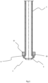
Figure 1 illustrates a male flared tube in a front view. -
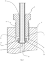
Figure 2 illustrates a tube connecting device according to the present invention, having a male flared tube in cross-sectional view. -
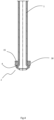
Figure 3 illustrates a male flared tube with a pin shrinking-fit the ring thereon. -
Figure 4 illustrates a male flared tube with the ring fixed thereon by crimping. -
Figure 5 illustrates a female flared tube in a front view. -
Figure 6 illustrates a female flared tube arranged in a connector and threaded sleeve before screwing for connection. - The tube connecting device according to the invention comprises a tube (1) having a flared end (2), a connector (6) having a seating surface (10) for seating the flared end (2) of the tube (1), and a sleeve (5) threadably connected to the connector (6). The flared end (2) of the tube (1) defines a front surface (3) being of a conical form, and a rear surface (4) preferably being of a flat surface, i.e. perpendicular to the tube axis. There is fixed a ring (15) to the adjacent of the rear surface (4) of the flared end (2), i.e. before the connection is made.
- The fixation of the ring (15) can be rendered using a bonding agent to be applied on the rear surface (4) and then the ring (15) is pushed towards the rear surface (4) and maintained there for fixing. The bonding agent can also be applied to the tube portion (16) by the upper side of the rear surface. Alternatively, the bonding agent can only be applied to the tube portion (16) by the upper side of the rear end, i.e. without applying to the rear surface.
- The bonding agent to be used may preferably be a fast-effecting adhesive such as cyanoacrylate adhesives (also known as Super Glue™). The fixation of the ring (15) can alternatively be rendered by shrink-fit, which is achieved by inserting a pin (17) through the tube outlet (13) while the ring is maintained at the rear surface (4). The diameter of the pin would be slightly bigger than that of the inner diameter of the tube in this alternative. As a further alternative, the fixation of the ring (15) can be rendered by crimping wherein a crimping tool is applied tangentially on the ring to form a crimped surface (18) while it is maintained at the rear surface (4).
- The thickness of the ring (15) can be of any suitable size in use, it may preferably be between 1 to 3 mm. The ring (15) is at least partially coated by an anti-friction material selected from a material consisting of
- Molybdenum disulfide (MoS2), Polythetrafluoroetylene (PTFE), graphite, or polyethylene. The anti-firction material is at least applied to the upper surface of the ring, i.e. facing the sleeve. The coating may also be applied to the entire ring. The surface roughness of the ring to which an anti friction coating material to be applied may be Ra 1µm - 2µm.
- In case the fixation of the ring (15) is rendered by a bonding agent, the thickness of the bonding agent may preferably be between 0,01 to 0,2 mm, and more preferably between 0,02 to 0,07 mm.
- The ring (15) is formed to have an outer diameter to sufficiently cover the rear surface (4) of the flared end (2), and the ring (15) has an inner diameter through which the tube (1) can be comfortably passed from the other end which is not flared. It is appreciated that the rear surface (4) may be of some other forms other than being flat in which case the corresponding ring surface, i.e. its lower surface, has a complementary form.
Figure 5 and6 represent such an embodiment illustrating a "female" flared end wherein the rear surface (4) has a conical form so the relevant contacting surface of the ring does. - The connector (6) comprises a housing (9) formed annularly therein and a cavity (14) coaxially extending from the housing (9). The housing (9) and the cavity (14) together define a through opening in the connector (6) and the diameter of the cavity (14) is smaller than that of the housing (9). The connector (6) further comprises a seating surface (10) having a conical form tapering from the end of the housing to the start of the cavity (14).
- In use, the tube (1) is passed through the housing (9) and the front surface (3) of the flared end (2) is seated on the seating surface (10) of the connector (6) such that the tube axis is co-axial with the cavity (14) axis. The diameter of the tube outlet (13) is sized such that it is substantially same with the diameter of the cavity (14). The tapering angle of the front surface (3) is preferably formed to be 115° and it would increase little more, say 120°, to match the tapering angle of the seating surface (10) when the sleeve is screwed.
- Following seating the flared end (2) on the seating surface (10), the sleeve (5) encompassing the tube (1) along its axis via a through opening (11) is screwed to the connector (6), to its threaded portion (7), and the tip (8) of the sleeve (5) exerts axial force to the upper side of the ring (15) so that the front surface (3) of the flared end (2) sealingly abuts the seating surface (10) of the connector (6).
- The ring (15) is so fixed to the rear surface (4) that the torque required to break it off from the rear surface (4) is preferably between 0,3 to 20 Nm. More preferably, the subject torque is between 1 to 10 Nm, and most preferably the torque is between 3 to 7 Nm.
Claims (12)
- A tube connecting device comprising a tube (1) having a flared end (2) defining a conical front surface (3) and a rear surface (4); a threaded sleeve (5) having a through opening (11) for receiving the tube (1); a connector (6) having a conical seating surface (10) for receiving the front surface (3) of the flared end (2) and a threaded portion meshable with the threaded sleeve (5); a ring (15) arranged between the rear surface (4) of the flared end (2) and the threaded sleeve (5) when the threaded sleeve is screwed, characterized in
that the ring (15) is immovably connected to the adjacent of the rear surface (4) of the flared end (2) before the tube connection is made, the ring (15) maintains its fixation along the connection is made, the ring (15) is at least partially coated with anti-friction material and the anti-friction material is selected from a material consisting of molybdenum disulfide (MoS2), polytetrafluoroethylene (PTFE), graphite or polyethylene. - A tube connecting device according to claim 1, characterized in that the ring (15) is fixed to a tube portion (16) by the upper side of the rear surface (4).
- A tube connecting device according to claim 1, characterized in that a bonding agent is used for fixing the ring (15) to the rear surface (4).
- A tube connecting device according to claim 3, characterized in that the bonding agent is a cyanoacrylate adhesive.
- A tube connecting device according to claim 3, characterized in that the thickness of the bonding agent is between 0.01 and 0.2 mm.
- A tube connecting device according to claim 3, characterized in that the thickness of the bonding agent is between 0.02 and 0.07 mm.
- A tube connecting device according to one of the preceding claims, characterized in that the rear surface (4) is of flat form.
- A tube connection device according to one of the preceding claims , characterized in that the rear surface (4) is of conical form.
- A tube connecting device according to one of the preceding claims, characterized in that the flared end (2) is of a male form.
- A tube connecting device according to one of claims 1 to 8, characterized in that the flared end (2) is of female form.
- A tube connecting device according to one of the preceding claims, characterized in that the torque required to break the ring off from the rear surface (4) is between 0.3 and 20 Nm.
- A tube connecting device according to claim 11, characterized in that the torque required to break the ring off from the rear surface (4) is between 1 and 10 Nm.
Applications Claiming Priority (1)
| Application Number | Priority Date | Filing Date | Title |
|---|---|---|---|
| DE102017113195.7A DE102017113195A1 (en) | 2017-06-14 | 2017-06-14 | Rohrverbindungsvorichtung |
Publications (2)
| Publication Number | Publication Date |
|---|---|
| EP3415800A1 EP3415800A1 (en) | 2018-12-19 |
| EP3415800B1 true EP3415800B1 (en) | 2024-07-10 |
Family
ID=62116168
Family Applications (1)
| Application Number | Title | Priority Date | Filing Date |
|---|---|---|---|
| EP18020189.9A Active EP3415800B1 (en) | 2017-06-14 | 2018-05-03 | Tube connecting device |
Country Status (4)
| Country | Link |
|---|---|
| US (1) | US10895336B2 (en) |
| EP (1) | EP3415800B1 (en) |
| CN (1) | CN109084102A (en) |
| DE (1) | DE102017113195A1 (en) |
Families Citing this family (5)
| Publication number | Priority date | Publication date | Assignee | Title |
|---|---|---|---|---|
| CN110848481A (en) * | 2019-09-30 | 2020-02-28 | 北汽福田汽车股份有限公司 | Pipe joint, engine assembly and vehicle |
| WO2022003894A1 (en) * | 2020-07-02 | 2022-01-06 | 株式会社サンギ | Seal device |
| DK4019821T3 (en) * | 2020-12-23 | 2023-07-03 | Walter Stauffenberg Gmbh & Co Kg | Pipe connection |
| US12173814B2 (en) | 2022-03-18 | 2024-12-24 | Martinrea International US Inc. | Female ISO flare union with integrated mating brake ISO F flare port |
| WO2024039962A1 (en) * | 2022-08-17 | 2024-02-22 | Martinrea International US Inc. | High pressure tube end form such as incorporated into a hydrogen fuel fill tube |
Family Cites Families (20)
| Publication number | Priority date | Publication date | Assignee | Title |
|---|---|---|---|---|
| US1893441A (en) * | 1930-07-07 | 1933-01-03 | Arthur L Parker | Tube coupling |
| US2026168A (en) * | 1934-04-30 | 1935-12-31 | Packless Metal Products Corp | Leak-proof coupling for metal tubing |
| US2300584A (en) * | 1940-06-22 | 1942-11-03 | Otis C Martin | Tube coupling |
| US2466521A (en) * | 1945-07-04 | 1949-04-05 | Weatherhead Co | Tube nut |
| JP2789197B2 (en) * | 1988-08-19 | 1998-08-20 | 臼井国際産業株式会社 | High-pressure metal pipe having a connection head and a method of forming the head |
| JP3307345B2 (en) * | 1998-10-29 | 2002-07-24 | トヨタ自動車株式会社 | Connection structure of tube |
| US6527304B1 (en) * | 2000-02-17 | 2003-03-04 | Ford Global Technologies, Inc. | Brake tube connector |
| GB2365937B (en) * | 2000-05-29 | 2002-08-07 | Usui Kokusai Sangyo Kk | High-pressure metal pipe with connection head, method of forming the head and connection washer for the connection head |
| DE10124874A1 (en) * | 2001-05-22 | 2002-11-28 | Voss Fluidtechnik Gmbh & Co Kg | Tube Fitting |
| ES2318221T3 (en) | 2004-08-03 | 2009-05-01 | Ti Automotive (Heidelberg) Gmbh | INSTALLATION OF CONNECTION OF DUCTS. |
| US8079621B2 (en) * | 2007-11-15 | 2011-12-20 | Lincoln Brass Works, Inc. | Reinforced bead tube design |
| DE202007016637U1 (en) * | 2007-11-27 | 2009-04-09 | Tube Technology Systems Ag | pipe connection |
| DE502008001944D1 (en) | 2008-06-17 | 2011-01-13 | Ti Automotive Heidelberg Gmbh | Screw element and pipe connection device for connecting pipes |
| EP2360405A1 (en) * | 2010-02-19 | 2011-08-24 | TI Automotive (Heidelberg) GmbH | Tube connection device |
| CN103604012B (en) * | 2013-04-13 | 2015-12-23 | 孙海潮 | A kind of connector element being exclusively used in split-type air conditioner connecting refrigerant lines road |
| DE102013111589B4 (en) * | 2013-08-14 | 2016-09-22 | Borgwarner Ludwigsburg Gmbh | Fuel vaporizer |
| JP6579656B2 (en) * | 2015-12-04 | 2019-09-25 | 臼井国際産業株式会社 | High pressure fuel injection pipe having connecting head and head forming method thereof |
| CN205716106U (en) * | 2016-06-28 | 2016-11-23 | 长城汽车股份有限公司 | Air-brake coupling hose and hydraulic brake line |
| CN206130354U (en) * | 2016-08-31 | 2017-04-26 | 浙江安德电器有限公司 | Air duct seal structure of gas cooking utensils |
| CN206130355U (en) * | 2016-10-13 | 2017-04-26 | 何志林 | Aviation fluid pipeline connects |
-
2017
- 2017-06-14 DE DE102017113195.7A patent/DE102017113195A1/en not_active Withdrawn
-
2018
- 2018-05-03 EP EP18020189.9A patent/EP3415800B1/en active Active
- 2018-05-23 US US15/987,242 patent/US10895336B2/en active Active
- 2018-05-28 CN CN201810524234.4A patent/CN109084102A/en active Pending
Also Published As
| Publication number | Publication date |
|---|---|
| CN109084102A (en) | 2018-12-25 |
| EP3415800A1 (en) | 2018-12-19 |
| US20180363814A1 (en) | 2018-12-20 |
| US10895336B2 (en) | 2021-01-19 |
| DE102017113195A1 (en) | 2018-12-20 |
Similar Documents
| Publication | Publication Date | Title |
|---|---|---|
| US10895336B2 (en) | Tube connecting device | |
| US10344898B2 (en) | Pull-up by torque fitting with female threaded nut and integral dynamic wedge | |
| EP1971799B1 (en) | Fitting for tube or pipe | |
| CN105339715B (en) | pipe connector | |
| US9249907B2 (en) | Fitting for connecting a pipe | |
| US20110204623A1 (en) | Pipe connection arrangement | |
| AU8421198A (en) | Connection of a metal pipe with a metal sleeve | |
| KR20120093836A (en) | Screwed pipe joint and method for the production thereof | |
| CN110552633B (en) | Threaded connection | |
| EP2101096A1 (en) | Extrude pipe connecting part with integrated single and double clamping ring | |
| CN103807525B (en) | For pipeline, particularly for the screw connection of automobile pipeline | |
| EP1425533B1 (en) | Support sleeve for use in a tube coupling and a coupling housing for use together with said sleeve | |
| US7837236B2 (en) | Pipe connection having a reshaped pipe | |
| EP2860433B1 (en) | Flared pipe connection arrangement | |
| CN109114322B (en) | Pipe joint | |
| JP4742222B2 (en) | Flare fitting | |
| JP4005114B1 (en) | Flare fastening structure of tube | |
| US8403371B1 (en) | Sprinkler unwinding piping | |
| EP3387311B1 (en) | A tube-to-tube connection device and method of same | |
| JP2009235814A (en) | Adaptor apparatus | |
| EP3379124B1 (en) | Unitary assembly and screw fitting for the reciprocal connection of a threaded end member and a pipe with a smooth surface |
Legal Events
| Date | Code | Title | Description |
|---|---|---|---|
| PUAI | Public reference made under article 153(3) epc to a published international application that has entered the european phase |
Free format text: ORIGINAL CODE: 0009012 |
|
| STAA | Information on the status of an ep patent application or granted ep patent |
Free format text: STATUS: THE APPLICATION HAS BEEN PUBLISHED |
|
| AK | Designated contracting states |
Kind code of ref document: A1 Designated state(s): AL AT BE BG CH CY CZ DE DK EE ES FI FR GB GR HR HU IE IS IT LI LT LU LV MC MK MT NL NO PL PT RO RS SE SI SK SM TR |
|
| AX | Request for extension of the european patent |
Extension state: BA ME |
|
| STAA | Information on the status of an ep patent application or granted ep patent |
Free format text: STATUS: REQUEST FOR EXAMINATION WAS MADE |
|
| 17P | Request for examination filed |
Effective date: 20190910 |
|
| RBV | Designated contracting states (corrected) |
Designated state(s): AL AT BE BG CH CY CZ DE DK EE ES FI FR GB GR HR HU IE IS IT LI LT LU LV MC MK MT NL NO PL PT RO RS SE SI SK SM TR |
|
| STAA | Information on the status of an ep patent application or granted ep patent |
Free format text: STATUS: EXAMINATION IS IN PROGRESS |
|
| 17Q | First examination report despatched |
Effective date: 20210607 |
|
| GRAP | Despatch of communication of intention to grant a patent |
Free format text: ORIGINAL CODE: EPIDOSNIGR1 |
|
| STAA | Information on the status of an ep patent application or granted ep patent |
Free format text: STATUS: GRANT OF PATENT IS INTENDED |
|
| RIC1 | Information provided on ipc code assigned before grant |
Ipc: B60T 17/04 20060101ALI20240313BHEP Ipc: F16L 19/05 20060101ALI20240313BHEP Ipc: F16L 19/028 20060101AFI20240313BHEP |
|
| INTG | Intention to grant announced |
Effective date: 20240405 |
|
| RAP3 | Party data changed (applicant data changed or rights of an application transferred) |
Owner name: BANTBORU SANAYI VE TICARET ANONIM SIRKETI |
|
| GRAS | Grant fee paid |
Free format text: ORIGINAL CODE: EPIDOSNIGR3 |
|
| GRAA | (expected) grant |
Free format text: ORIGINAL CODE: 0009210 |
|
| STAA | Information on the status of an ep patent application or granted ep patent |
Free format text: STATUS: THE PATENT HAS BEEN GRANTED |
|
| AK | Designated contracting states |
Kind code of ref document: B1 Designated state(s): AL AT BE BG CH CY CZ DE DK EE ES FI FR GB GR HR HU IE IS IT LI LT LU LV MC MK MT NL NO PL PT RO RS SE SI SK SM TR |
|
| REG | Reference to a national code |
Ref country code: CH Ref legal event code: EP |
|
| REG | Reference to a national code |
Ref country code: DE Ref legal event code: R096 Ref document number: 602018071486 Country of ref document: DE |
|
| REG | Reference to a national code |
Ref country code: LT Ref legal event code: MG9D |
|
| REG | Reference to a national code |
Ref country code: NL Ref legal event code: MP Effective date: 20240710 |
|
| PG25 | Lapsed in a contracting state [announced via postgrant information from national office to epo] |
Ref country code: PT Free format text: LAPSE BECAUSE OF FAILURE TO SUBMIT A TRANSLATION OF THE DESCRIPTION OR TO PAY THE FEE WITHIN THE PRESCRIBED TIME-LIMIT Effective date: 20241111 |
|
| REG | Reference to a national code |
Ref country code: AT Ref legal event code: MK05 Ref document number: 1702295 Country of ref document: AT Kind code of ref document: T Effective date: 20240710 |
|
| PG25 | Lapsed in a contracting state [announced via postgrant information from national office to epo] |
Ref country code: NL Free format text: LAPSE BECAUSE OF FAILURE TO SUBMIT A TRANSLATION OF THE DESCRIPTION OR TO PAY THE FEE WITHIN THE PRESCRIBED TIME-LIMIT Effective date: 20240710 |
|
| PG25 | Lapsed in a contracting state [announced via postgrant information from national office to epo] |
Ref country code: PT Free format text: LAPSE BECAUSE OF FAILURE TO SUBMIT A TRANSLATION OF THE DESCRIPTION OR TO PAY THE FEE WITHIN THE PRESCRIBED TIME-LIMIT Effective date: 20241111 Ref country code: NL Free format text: LAPSE BECAUSE OF FAILURE TO SUBMIT A TRANSLATION OF THE DESCRIPTION OR TO PAY THE FEE WITHIN THE PRESCRIBED TIME-LIMIT Effective date: 20240710 |
|
| PG25 | Lapsed in a contracting state [announced via postgrant information from national office to epo] |
Ref country code: NO Free format text: LAPSE BECAUSE OF FAILURE TO SUBMIT A TRANSLATION OF THE DESCRIPTION OR TO PAY THE FEE WITHIN THE PRESCRIBED TIME-LIMIT Effective date: 20241010 |
|
| PG25 | Lapsed in a contracting state [announced via postgrant information from national office to epo] |
Ref country code: GR Free format text: LAPSE BECAUSE OF FAILURE TO SUBMIT A TRANSLATION OF THE DESCRIPTION OR TO PAY THE FEE WITHIN THE PRESCRIBED TIME-LIMIT Effective date: 20241011 Ref country code: FI Free format text: LAPSE BECAUSE OF FAILURE TO SUBMIT A TRANSLATION OF THE DESCRIPTION OR TO PAY THE FEE WITHIN THE PRESCRIBED TIME-LIMIT Effective date: 20240710 Ref country code: PL Free format text: LAPSE BECAUSE OF FAILURE TO SUBMIT A TRANSLATION OF THE DESCRIPTION OR TO PAY THE FEE WITHIN THE PRESCRIBED TIME-LIMIT Effective date: 20240710 |
|
| PG25 | Lapsed in a contracting state [announced via postgrant information from national office to epo] |
Ref country code: BG Free format text: LAPSE BECAUSE OF FAILURE TO SUBMIT A TRANSLATION OF THE DESCRIPTION OR TO PAY THE FEE WITHIN THE PRESCRIBED TIME-LIMIT Effective date: 20240710 |
|
| PG25 | Lapsed in a contracting state [announced via postgrant information from national office to epo] |
Ref country code: LV Free format text: LAPSE BECAUSE OF FAILURE TO SUBMIT A TRANSLATION OF THE DESCRIPTION OR TO PAY THE FEE WITHIN THE PRESCRIBED TIME-LIMIT Effective date: 20240710 |
|
| PG25 | Lapsed in a contracting state [announced via postgrant information from national office to epo] |
Ref country code: IS Free format text: LAPSE BECAUSE OF FAILURE TO SUBMIT A TRANSLATION OF THE DESCRIPTION OR TO PAY THE FEE WITHIN THE PRESCRIBED TIME-LIMIT Effective date: 20241110 Ref country code: AT Free format text: LAPSE BECAUSE OF FAILURE TO SUBMIT A TRANSLATION OF THE DESCRIPTION OR TO PAY THE FEE WITHIN THE PRESCRIBED TIME-LIMIT Effective date: 20240710 |
|
| PG25 | Lapsed in a contracting state [announced via postgrant information from national office to epo] |
Ref country code: HR Free format text: LAPSE BECAUSE OF FAILURE TO SUBMIT A TRANSLATION OF THE DESCRIPTION OR TO PAY THE FEE WITHIN THE PRESCRIBED TIME-LIMIT Effective date: 20240710 |
|
| PG25 | Lapsed in a contracting state [announced via postgrant information from national office to epo] |
Ref country code: ES Free format text: LAPSE BECAUSE OF FAILURE TO SUBMIT A TRANSLATION OF THE DESCRIPTION OR TO PAY THE FEE WITHIN THE PRESCRIBED TIME-LIMIT Effective date: 20240710 Ref country code: RS Free format text: LAPSE BECAUSE OF FAILURE TO SUBMIT A TRANSLATION OF THE DESCRIPTION OR TO PAY THE FEE WITHIN THE PRESCRIBED TIME-LIMIT Effective date: 20241010 |
|
| PG25 | Lapsed in a contracting state [announced via postgrant information from national office to epo] |
Ref country code: RS Free format text: LAPSE BECAUSE OF FAILURE TO SUBMIT A TRANSLATION OF THE DESCRIPTION OR TO PAY THE FEE WITHIN THE PRESCRIBED TIME-LIMIT Effective date: 20241010 Ref country code: PL Free format text: LAPSE BECAUSE OF FAILURE TO SUBMIT A TRANSLATION OF THE DESCRIPTION OR TO PAY THE FEE WITHIN THE PRESCRIBED TIME-LIMIT Effective date: 20240710 Ref country code: NO Free format text: LAPSE BECAUSE OF FAILURE TO SUBMIT A TRANSLATION OF THE DESCRIPTION OR TO PAY THE FEE WITHIN THE PRESCRIBED TIME-LIMIT Effective date: 20241010 Ref country code: LV Free format text: LAPSE BECAUSE OF FAILURE TO SUBMIT A TRANSLATION OF THE DESCRIPTION OR TO PAY THE FEE WITHIN THE PRESCRIBED TIME-LIMIT Effective date: 20240710 Ref country code: IS Free format text: LAPSE BECAUSE OF FAILURE TO SUBMIT A TRANSLATION OF THE DESCRIPTION OR TO PAY THE FEE WITHIN THE PRESCRIBED TIME-LIMIT Effective date: 20241110 Ref country code: HR Free format text: LAPSE BECAUSE OF FAILURE TO SUBMIT A TRANSLATION OF THE DESCRIPTION OR TO PAY THE FEE WITHIN THE PRESCRIBED TIME-LIMIT Effective date: 20240710 Ref country code: GR Free format text: LAPSE BECAUSE OF FAILURE TO SUBMIT A TRANSLATION OF THE DESCRIPTION OR TO PAY THE FEE WITHIN THE PRESCRIBED TIME-LIMIT Effective date: 20241011 Ref country code: FI Free format text: LAPSE BECAUSE OF FAILURE TO SUBMIT A TRANSLATION OF THE DESCRIPTION OR TO PAY THE FEE WITHIN THE PRESCRIBED TIME-LIMIT Effective date: 20240710 Ref country code: ES Free format text: LAPSE BECAUSE OF FAILURE TO SUBMIT A TRANSLATION OF THE DESCRIPTION OR TO PAY THE FEE WITHIN THE PRESCRIBED TIME-LIMIT Effective date: 20240710 Ref country code: BG Free format text: LAPSE BECAUSE OF FAILURE TO SUBMIT A TRANSLATION OF THE DESCRIPTION OR TO PAY THE FEE WITHIN THE PRESCRIBED TIME-LIMIT Effective date: 20240710 Ref country code: AT Free format text: LAPSE BECAUSE OF FAILURE TO SUBMIT A TRANSLATION OF THE DESCRIPTION OR TO PAY THE FEE WITHIN THE PRESCRIBED TIME-LIMIT Effective date: 20240710 |
|
| REG | Reference to a national code |
Ref country code: DE Ref legal event code: R097 Ref document number: 602018071486 Country of ref document: DE |
|
| PG25 | Lapsed in a contracting state [announced via postgrant information from national office to epo] |
Ref country code: SM Free format text: LAPSE BECAUSE OF FAILURE TO SUBMIT A TRANSLATION OF THE DESCRIPTION OR TO PAY THE FEE WITHIN THE PRESCRIBED TIME-LIMIT Effective date: 20240710 Ref country code: DK Free format text: LAPSE BECAUSE OF FAILURE TO SUBMIT A TRANSLATION OF THE DESCRIPTION OR TO PAY THE FEE WITHIN THE PRESCRIBED TIME-LIMIT Effective date: 20240710 Ref country code: RO Free format text: LAPSE BECAUSE OF FAILURE TO SUBMIT A TRANSLATION OF THE DESCRIPTION OR TO PAY THE FEE WITHIN THE PRESCRIBED TIME-LIMIT Effective date: 20240710 |
|
| PG25 | Lapsed in a contracting state [announced via postgrant information from national office to epo] |
Ref country code: EE Free format text: LAPSE BECAUSE OF FAILURE TO SUBMIT A TRANSLATION OF THE DESCRIPTION OR TO PAY THE FEE WITHIN THE PRESCRIBED TIME-LIMIT Effective date: 20240710 |
|
| PG25 | Lapsed in a contracting state [announced via postgrant information from national office to epo] |
Ref country code: CZ Free format text: LAPSE BECAUSE OF FAILURE TO SUBMIT A TRANSLATION OF THE DESCRIPTION OR TO PAY THE FEE WITHIN THE PRESCRIBED TIME-LIMIT Effective date: 20240710 |
|
| PG25 | Lapsed in a contracting state [announced via postgrant information from national office to epo] |
Ref country code: SK Free format text: LAPSE BECAUSE OF FAILURE TO SUBMIT A TRANSLATION OF THE DESCRIPTION OR TO PAY THE FEE WITHIN THE PRESCRIBED TIME-LIMIT Effective date: 20240710 Ref country code: IT Free format text: LAPSE BECAUSE OF FAILURE TO SUBMIT A TRANSLATION OF THE DESCRIPTION OR TO PAY THE FEE WITHIN THE PRESCRIBED TIME-LIMIT Effective date: 20240710 |
|
| PLBE | No opposition filed within time limit |
Free format text: ORIGINAL CODE: 0009261 |
|
| STAA | Information on the status of an ep patent application or granted ep patent |
Free format text: STATUS: NO OPPOSITION FILED WITHIN TIME LIMIT |
|
| 26N | No opposition filed |
Effective date: 20250411 |
|
| PG25 | Lapsed in a contracting state [announced via postgrant information from national office to epo] |
Ref country code: SE Free format text: LAPSE BECAUSE OF FAILURE TO SUBMIT A TRANSLATION OF THE DESCRIPTION OR TO PAY THE FEE WITHIN THE PRESCRIBED TIME-LIMIT Effective date: 20240710 |
|
| REG | Reference to a national code |
Ref country code: DE Ref legal event code: R119 Ref document number: 602018071486 Country of ref document: DE |
|
| REG | Reference to a national code |
Ref country code: CH Ref legal event code: H13 Free format text: ST27 STATUS EVENT CODE: U-0-0-H10-H13 (AS PROVIDED BY THE NATIONAL OFFICE) Effective date: 20251223 |
|
| PG25 | Lapsed in a contracting state [announced via postgrant information from national office to epo] |
Ref country code: LU Free format text: LAPSE BECAUSE OF NON-PAYMENT OF DUE FEES Effective date: 20250503 |
|
| PG25 | Lapsed in a contracting state [announced via postgrant information from national office to epo] |
Ref country code: CH Free format text: LAPSE BECAUSE OF NON-PAYMENT OF DUE FEES Effective date: 20250531 |
|
| GBPC | Gb: european patent ceased through non-payment of renewal fee |
Effective date: 20250503 |
|
| REG | Reference to a national code |
Ref country code: BE Ref legal event code: MM Effective date: 20250531 |
|
| PG25 | Lapsed in a contracting state [announced via postgrant information from national office to epo] |
Ref country code: MC Free format text: LAPSE BECAUSE OF FAILURE TO SUBMIT A TRANSLATION OF THE DESCRIPTION OR TO PAY THE FEE WITHIN THE PRESCRIBED TIME-LIMIT Effective date: 20240710 |
|
| PG25 | Lapsed in a contracting state [announced via postgrant information from national office to epo] |
Ref country code: GB Free format text: LAPSE BECAUSE OF NON-PAYMENT OF DUE FEES Effective date: 20250503 |
|
| PG25 | Lapsed in a contracting state [announced via postgrant information from national office to epo] |
Ref country code: DE Free format text: LAPSE BECAUSE OF NON-PAYMENT OF DUE FEES Effective date: 20251202 Ref country code: IE Free format text: LAPSE BECAUSE OF NON-PAYMENT OF DUE FEES Effective date: 20250503 |
|
| PG25 | Lapsed in a contracting state [announced via postgrant information from national office to epo] |
Ref country code: BE Free format text: LAPSE BECAUSE OF NON-PAYMENT OF DUE FEES Effective date: 20250531 |
|
| PG25 | Lapsed in a contracting state [announced via postgrant information from national office to epo] |
Ref country code: FR Free format text: LAPSE BECAUSE OF NON-PAYMENT OF DUE FEES Effective date: 20250531 |