EP3415720A1 - Turbine tip shroud assembly with plural shroud segments having internal cooling passages - Google Patents
Turbine tip shroud assembly with plural shroud segments having internal cooling passages Download PDFInfo
- Publication number
- EP3415720A1 EP3415720A1 EP18166426.9A EP18166426A EP3415720A1 EP 3415720 A1 EP3415720 A1 EP 3415720A1 EP 18166426 A EP18166426 A EP 18166426A EP 3415720 A1 EP3415720 A1 EP 3415720A1
- Authority
- EP
- European Patent Office
- Prior art keywords
- shroud
- chamber
- sealing member
- segment
- internal cooling
- Prior art date
- Legal status (The legal status is an assumption and is not a legal conclusion. Google has not performed a legal analysis and makes no representation as to the accuracy of the status listed.)
- Granted
Links
Images


Classifications
-
- F—MECHANICAL ENGINEERING; LIGHTING; HEATING; WEAPONS; BLASTING
- F01—MACHINES OR ENGINES IN GENERAL; ENGINE PLANTS IN GENERAL; STEAM ENGINES
- F01D—NON-POSITIVE DISPLACEMENT MACHINES OR ENGINES, e.g. STEAM TURBINES
- F01D25/00—Component parts, details, or accessories, not provided for in, or of interest apart from, other groups
- F01D25/08—Cooling; Heating; Heat-insulation
- F01D25/12—Cooling
-
- F—MECHANICAL ENGINEERING; LIGHTING; HEATING; WEAPONS; BLASTING
- F01—MACHINES OR ENGINES IN GENERAL; ENGINE PLANTS IN GENERAL; STEAM ENGINES
- F01D—NON-POSITIVE DISPLACEMENT MACHINES OR ENGINES, e.g. STEAM TURBINES
- F01D11/00—Preventing or minimising internal leakage of working-fluid, e.g. between stages
- F01D11/08—Preventing or minimising internal leakage of working-fluid, e.g. between stages for sealing space between rotor blade tips and stator
- F01D11/14—Adjusting or regulating tip-clearance, i.e. distance between rotor-blade tips and stator casing
- F01D11/20—Actively adjusting tip-clearance
- F01D11/24—Actively adjusting tip-clearance by selectively cooling-heating stator or rotor components
-
- F—MECHANICAL ENGINEERING; LIGHTING; HEATING; WEAPONS; BLASTING
- F01—MACHINES OR ENGINES IN GENERAL; ENGINE PLANTS IN GENERAL; STEAM ENGINES
- F01D—NON-POSITIVE DISPLACEMENT MACHINES OR ENGINES, e.g. STEAM TURBINES
- F01D25/00—Component parts, details, or accessories, not provided for in, or of interest apart from, other groups
- F01D25/24—Casings; Casing parts, e.g. diaphragms, casing fastenings
- F01D25/246—Fastening of diaphragms or stator-rings
-
- F—MECHANICAL ENGINEERING; LIGHTING; HEATING; WEAPONS; BLASTING
- F01—MACHINES OR ENGINES IN GENERAL; ENGINE PLANTS IN GENERAL; STEAM ENGINES
- F01D—NON-POSITIVE DISPLACEMENT MACHINES OR ENGINES, e.g. STEAM TURBINES
- F01D5/00—Blades; Blade-carrying members; Heating, heat-insulating, cooling or antivibration means on the blades or the members
- F01D5/12—Blades
- F01D5/22—Blade-to-blade connections, e.g. for damping vibrations
- F01D5/225—Blade-to-blade connections, e.g. for damping vibrations by shrouding
-
- F—MECHANICAL ENGINEERING; LIGHTING; HEATING; WEAPONS; BLASTING
- F01—MACHINES OR ENGINES IN GENERAL; ENGINE PLANTS IN GENERAL; STEAM ENGINES
- F01D—NON-POSITIVE DISPLACEMENT MACHINES OR ENGINES, e.g. STEAM TURBINES
- F01D9/00—Stators
- F01D9/02—Nozzles; Nozzle boxes; Stator blades; Guide conduits, e.g. individual nozzles
- F01D9/04—Nozzles; Nozzle boxes; Stator blades; Guide conduits, e.g. individual nozzles forming ring or sector
-
- F—MECHANICAL ENGINEERING; LIGHTING; HEATING; WEAPONS; BLASTING
- F05—INDEXING SCHEMES RELATING TO ENGINES OR PUMPS IN VARIOUS SUBCLASSES OF CLASSES F01-F04
- F05D—INDEXING SCHEME FOR ASPECTS RELATING TO NON-POSITIVE-DISPLACEMENT MACHINES OR ENGINES, GAS-TURBINES OR JET-PROPULSION PLANTS
- F05D2240/00—Components
- F05D2240/10—Stators
- F05D2240/11—Shroud seal segments
-
- F—MECHANICAL ENGINEERING; LIGHTING; HEATING; WEAPONS; BLASTING
- F05—INDEXING SCHEMES RELATING TO ENGINES OR PUMPS IN VARIOUS SUBCLASSES OF CLASSES F01-F04
- F05D—INDEXING SCHEME FOR ASPECTS RELATING TO NON-POSITIVE-DISPLACEMENT MACHINES OR ENGINES, GAS-TURBINES OR JET-PROPULSION PLANTS
- F05D2240/00—Components
- F05D2240/10—Stators
- F05D2240/12—Fluid guiding means, e.g. vanes
- F05D2240/125—Fluid guiding means, e.g. vanes related to the tip of a stator vane
-
- F—MECHANICAL ENGINEERING; LIGHTING; HEATING; WEAPONS; BLASTING
- F05—INDEXING SCHEMES RELATING TO ENGINES OR PUMPS IN VARIOUS SUBCLASSES OF CLASSES F01-F04
- F05D—INDEXING SCHEME FOR ASPECTS RELATING TO NON-POSITIVE-DISPLACEMENT MACHINES OR ENGINES, GAS-TURBINES OR JET-PROPULSION PLANTS
- F05D2240/00—Components
- F05D2240/55—Seals
- F05D2240/56—Brush seals
-
- F—MECHANICAL ENGINEERING; LIGHTING; HEATING; WEAPONS; BLASTING
- F05—INDEXING SCHEMES RELATING TO ENGINES OR PUMPS IN VARIOUS SUBCLASSES OF CLASSES F01-F04
- F05D—INDEXING SCHEME FOR ASPECTS RELATING TO NON-POSITIVE-DISPLACEMENT MACHINES OR ENGINES, GAS-TURBINES OR JET-PROPULSION PLANTS
- F05D2260/00—Function
- F05D2260/20—Heat transfer, e.g. cooling
- F05D2260/201—Heat transfer, e.g. cooling by impingement of a fluid
-
- Y—GENERAL TAGGING OF NEW TECHNOLOGICAL DEVELOPMENTS; GENERAL TAGGING OF CROSS-SECTIONAL TECHNOLOGIES SPANNING OVER SEVERAL SECTIONS OF THE IPC; TECHNICAL SUBJECTS COVERED BY FORMER USPC CROSS-REFERENCE ART COLLECTIONS [XRACs] AND DIGESTS
- Y02—TECHNOLOGIES OR APPLICATIONS FOR MITIGATION OR ADAPTATION AGAINST CLIMATE CHANGE
- Y02T—CLIMATE CHANGE MITIGATION TECHNOLOGIES RELATED TO TRANSPORTATION
- Y02T50/00—Aeronautics or air transport
- Y02T50/60—Efficient propulsion technologies, e.g. for aircraft
Definitions
- the present disclosure generally relates to a turbine tip shroud assembly and, more particularly, to a turbine tip shroud assembly with plural shroud segments having internal cooling passages.
- Gas turbine engines are generally used in a wide range of applications, such as aircraft engines and auxiliary power units.
- air is compressed in a compressor, mixed with fuel, and ignited in a combustor to generate hot combustion gases, which flow downstream into a turbine section.
- the turbine section includes airfoils, such as stator vanes and rotor blades, disposed in an alternating sequence along the axial length of a generally annular hot gas flow path.
- the rotor blades are mounted at the periphery of one or more rotor disks that are coupled in turn to a main engine shaft.
- Hot combustion gases are delivered from the engine combustor to the annular hot gas flow path, thus resulting in rotary driving of the rotor disks to provide an engine output.
- a shroud assembly for a gas turbine engine.
- the shroud assembly is configured to receive a cooling fluid flow.
- the shroud assembly includes a shroud support that extends arcuately about an axis.
- the shroud assembly also includes a plurality of shroud segments that are attached to the shroud support and that are arranged annularly about the axis at different circumferential positions with respect to the axis.
- At least one of the plurality of shroud segments includes an internal cooling passage that extends through the shroud segment.
- the shroud segment also includes at least one inlet for receiving and directing the cooling fluid flow into the internal cooling passage.
- the shroud segment includes at least one outlet for outputting the cooling fluid flow from the internal cooling passage to a backflow cavity of the shroud assembly.
- the internal cooling passage is substantially hermetically sealed from the at least one inlet to the at least one outlet.
- a method of manufacturing a shroud assembly that is configured to receive a cooling fluid flow.
- the method includes providing a shroud support that extends arcuately about an axis.
- the shroud support includes a shroud support inlet.
- the method also includes attaching a plurality of shroud segments to the shroud support at different circumferential positions about the axis to arrange the plurality of shroud segments annularly about the axis.
- At least one of the plurality of shroud segments includes an internal cooling passage that extends therethrough from an inlet to at least one outlet.
- the method includes fluidly connecting the inlet of the internal cooling passage to the shroud support inlet.
- the internal cooling passage is substantially hermetically sealed from the inlet to the at least one outlet.
- the at least one outlet is fluidly connected to a backflow cavity of the shroud assembly.
- a gas turbine engine includes a rotor assembly of a turbine section.
- the rotor assembly includes a turbine blade.
- the gas turbine engine also includes a shroud assembly of the turbine section configured to receive a cooling fluid flow.
- the shroud assembly includes a shroud support that extends arcuately about an axis.
- the shroud assembly also includes a plurality of shroud segments that are attached to the shroud support and that are arranged annularly about the axis at different circumferential positions with respect to the axis. At least one of the plurality of shroud segments includes an inner diameter surface configured to oppose the turbine blade as the turbine blade rotates about the axis.
- the shroud segment also includes an internal cooling passage that extends through the at least one of the plurality of shroud segments.
- the shroud segment includes at least one inlet for receiving and directing the cooling fluid flow into the internal cooling passage. Furthermore, the shroud segment includes at least one outlet for outputting the cooling fluid flow from the internal cooling passage.
- the internal cooling passage is substantially hermetically sealed from the at least one inlet to the at least one outlet.
- the internal cooling passage includes a first chamber that is partly defined by a first backside surface, which faces opposite the inner diameter surface.
- the internal cooling passage includes a second chamber that is partly defined by a second backside surface, which faces opposite the inner diameter surface.
- the internal cooling passage includes a first impingement aperture directed into the first chamber generally toward the first backside surface.
- the internal cooling passage includes a second impingement aperture directed into the second chamber generally toward the second backside surface.
- the internal cooling passage is configured to direct the cooling fluid flow from the first impingement aperture into the first chamber and downstream into the second
- exemplary embodiments disclosed herein include gas turbine engines with one or more turbine shroud assemblies having improved cooling characteristics. Methods of manufacturing the turbine shroud assembly are also disclosed.
- exemplary embodiments include a turbine shroud assembly with internal impingement cooling passages configured for internally cooling components of the shroud assembly.
- a shroud assembly is disclosed according to example embodiments, wherein the assembly includes a plurality of shroud segments that are independently attached and substantially sealed to a shroud support case.
- the shroud segments and the shroud support case cooperate to define cooling flow passages for cooling the shroud segments and for directing the cooling fluid (e.g., air) to flow back into the core flow.
- the shroud segments may include internal cooling passages as well.
- the internal cooling passages may be airtight except for the one or more defined inlets and the one or more defined outlets of the shroud segment.
- the internal cooling passages may impinge two or more times in succession.
- the shroud segment may include an internal cooling passage with at least two impingement apertures arranged in series with respect to the flow direction of the passage. Accordingly, the cooling effectiveness for a given amount of cooling flow is increased substantially.
- FIG. 1 is a cross-sectional view of a gas turbine engine 100 according to an exemplary embodiment.
- FIG. 1 depicts a turbofan engine, in general, exemplary embodiments discussed herein may be applicable to another type of engine without departing from the scope of the present disclosure.
- the gas turbine engine 100 may form part of, for example, an auxiliary power unit for an aircraft or a propulsion system for an aircraft.
- the gas turbine engine 100 may be included on another vehicle without departing from the scope of the present disclosure.
- the gas turbine engine 100 may also be supported by a stationary mount in some embodiments.
- the gas turbine engine 100 has an overall construction and operation that is generally understood by persons skilled in the art.
- the gas turbine engine 100 may be disposed in an engine case 101 and may include a fan section 120, a compressor section 130, a combustion section 140, a turbine section 150, and an exhaust section 160, which are arranged sequentially along a longitudinal axis 180.
- the gas turbine engine 100 will be discussed with reference to a radial coordinate system. Accordingly, as used herein, the term “axial” refers to a direction along the longitudinal axis 180. A radial axis 190 is also included in FIG. 1 for reference purposes, and the term “radial” as used herein refers to a direction along the radial axis 190 or along another line extending radially with respect to the axis 180. Moreover, the term “circumferential” as used herein refers to a direction extending around or about the axis 180, at a particular radial distance from the axis 180.
- the fan section 120 may include a fan, which draws in and accelerates air. A fraction of the accelerated air from the fan section 120 is directed through a bypass section 170 to provide a forward thrust. The remaining fraction of air exhausted from the fan is directed into the compressor section 130.
- the compressor section 130 may include a series of compressors that raise the pressure of the air directed into it from the fan section 120.
- the compressors may direct the compressed air into the combustion section 140.
- the high pressure air is mixed with fuel, which is combusted.
- the post-combustion air is then directed into the turbine section 150.
- the turbine section 150 may include a series of rotor assemblies 192 and stator assemblies 194, both of which are represented schematically in FIG. 1 .
- the turbine section 150 may also include one or more shroud assemblies 210, which are also represented schematically.
- the shroud assembly 210 may generally encircle a respective rotor assembly 192.
- the shroud assembly 210 may encircle the tips of blades of the rotor assembly 192 and, thus, may be referred to as a turbine tip shroud assembly.
- post-combustion air from the combustion section 140 may be directed by the stator assembly 194 toward blades included in the rotor assembly 192.
- the post-conduction air impinges upon the rotor blades, thereby driving and rotating the rotor assembly 192 relative to the turbine shroud assembly 210, causing the rotor assembly 192 to rotate a main engine shaft for energy extraction.
- the flow may be directed through a propulsion nozzle disposed in the exhaust section 160 to provide additional forward thrust.
- the shroud assembly 210 may include one or more features of the present disclosure that promote cooling. Manufacturing techniques of the present disclosure are also discussed below for providing the shroud assembly 210 with the cooling features of the present disclosure.
- the turbine shroud assembly 210 may be substantially annular and may extend continuously in a circumferential direction about the longitudinal axis 180 ( FIG. 2 ).
- the turbine shroud assembly 210 includes a leading edge 211 and a trailing edge 213, which are separated at a distance along the longitudinal axis 180.
- the leading edge 211 faces generally in a forward direction along the axis 180
- the trailing edge 213 faces generally in a rearward direction along the axis 180.
- the turbine shroud assembly 210 may include a shroud support 214.
- the shroud support 214 may be a substantially unitary, one-piece, annular component with at least a portion that extends continuously about the axis 180.
- the shroud support 214 may include an outer diameter portion 216 and an inner diameter portion 218.
- the outer diameter portion 216 may be fixedly attached to the engine case 101 ( FIG. 1 ) or other surrounding support structure.
- the inner diameter portion 218 may include an inner ring 220.
- a circumferential segment of the inner ring 220 is shown in FIG. 3 and is shown in the section view of FIG. 4 .
- the inner ring 220 may include an inner diameter surface 222.
- the inner ring 220 may also include a support arm 224, which attaches the inner ring 220 to the outer diameter portion 216.
- the shroud support 214 may further include a trailing edge member 225 and a leading edge member 226 ( FIG. 3 ). As shown, the trailing edge member 225 and the leading edge member 226 may extend radially inward toward the longitudinal axis 180 from the inner ring 220. The trailing edge member 225 and the leading edge member 226 may be spaced apart along the axis 180.
- the turbine shroud assembly 210 may include a plurality of shroud segments 212 that are arranged annularly about the axis 180.
- the shroud segments 212 may be spaced circumferentially about the inner diameter surface 222 of the inner ring 220.
- An individual shroud segment 212 from a particular circumferential position (with respect to the axis 180) is shown in FIGS. 3-6 in detail.
- the shroud segment 212 is attached to a portion of the inner ring 220 in FIGS. 3 and 4 .
- the individual shroud segment 212 is shown in isolation in FIGS. 5 and 6 .
- the shroud segment 212 may be a monolithic, unitary, one-piece member. In other embodiments, the shroud segment 212 may be constructed from multiple pieces that are attached. It will be appreciated that the shroud segment 212 of FIGS. 4-6 may be representative of other shroud segments at different circumferential positions on the shroud support 214.
- the shroud segment 212 may include an outer diameter surface 228 and an opposite inner diameter surface 230.
- the shroud segment 212 may further include an upstream face 232 and an opposite downstream face 234, which are spaced apart along the axis 180.
- the shroud segment 212 may also include a first end 236 and a second end 238.
- the shroud segment 212 may be elongate and slightly arcuate in the circumferential direction between the first end 236 and the second end 238.
- the shroud segment 212 may further include a trailing edge rail 240 and a leading edge rail 242.
- the trailing edge rail 240 and the leading edge rail 242 may project radially outward from the outer diameter surface 228 and away from the axis 180.
- the outer diameter surface 228 may also include a first end recess 229 proximate the first end 236 and a second end recess 231 proximate the second end 238.
- the first end 236 and/or the second end 238 may include an arrangement of one or more grooves 233.
- the grooves 233 may include a first groove 235 that extends axially along the shroud segment 212, continuously from the upstream face 232 to the downstream face 234.
- the grooves 233 may also include a second groove 237 that extends radially along the leading edge rail 242 and that curves to intersect the first groove 235.
- the grooves 233 may further include a third groove 239 that extends radially along the trailing edge rail 240 and that curves to intersect the first groove 235.
- the grooves 233 may include a fourth groove 241 that extends diagonally between and that intersects both the first groove 235 and the third groove 239.
- the shroud segment 212 may further include a projection 244.
- the projection 244 may be annular and may project radially away from the outer diameter surface 228.
- the projection 244 may be disposed in a central region of the outer diameter surface 228, substantially centered axially between the upstream face 232 and the downstream face 234 and/or substantially centered circumferentially between the first end 236 and the second end 238.
- the projection 244 may be hollow, and the inner diameter of the projection 244 may be threaded in some embodiments.
- the shroud segment 212 may include at least one internal cooling passage 246 as shown in FIGS. 8, 9 , and 10 . As shown in FIG. 8 , the projection 244 may define an inlet 248 of the internal cooling passage 246.
- the passage 246 of the shroud segment 212 may include a first chamber 250 and a second chamber 252.
- the first and second chambers 250, 252 may have a cross section that is elongated along the axis 180 and that extends substantially parallel to the axis 180.
- the first chamber 250 and the second chamber 252 may extend in the circumferential direction as well.
- the first and second chambers 250, 252 may be disposed proximate the trailing edge 213 and may be overlapped in the radial direction as shown.
- the first chamber 250 may be disposed outboard radially with respect to the second chamber 252 (i.e., the second chamber 252 may be disposed closer to the axis 180 in the radial direction as compared to the first chamber 250).
- the second chamber 252 may be partly defined by a trailing backside surface 221 of the shroud segment 212 (i.e., the surface opposite the inner diameter surface 230 proximate the trailing edge 213).
- the first and second chambers 250, 252 may be fluidly connected by one or more first impingement apertures 253.
- the first impingement apertures 253 may extend radially through an internal wall separating the first and second chambers 250, 252.
- the passage 246 of the shroud segment 212 may further include a third chamber 254 and a fourth chamber 256 as shown in FIGS. 9 and 10 .
- the third and fourth chambers 254, 256 may have a cross section that is elongated along the axis 180 and that extends substantially parallel to the axis 180.
- the third chamber 254 and the fourth chamber 256 may extend in the circumferential direction as well.
- the third chamber 254 and the fourth chamber 256 may be disposed proximate the leading edge 211 and may be overlapped in the radial direction as shown.
- the third chamber 254 may be disposed outboard radially with respect to the fourth chamber 256.
- the fourth chamber 256 may be defined by a forward backside surface 223 of the shroud segment 212 (i.e., the surface opposite the inner diameter surface 230 proximate the leading edge 211).
- the third chamber 254 may be fluidly connected to the second chamber 252 via an intermediate opening 227 as shown in FIGS. 9 and 10 .
- the intermediate opening 227 may be relatively wide so as to facilitate fluid flow from the second chamber 252 to the third chamber 254.
- the third chamber 254 may be fluidly connected to the fourth chamber 256 by one or more second impingement apertures 255.
- the second impingement apertures may extend radially through an internal wall separating the third and fourth chambers 254, 256.
- the third impingement aperture 243 may fluidly connect the first chamber 250 and the fourth chamber 256.
- the shroud segment 212 may define one or more outlets 258 of the internal cooling passage 246 ( FIGS. 6 and 10 ).
- the outlets 258 may be circular through-holes that extend radially from the fourth chamber 256 and through the outer diameter surface 228.
- the outlets 258 may be disposed proximate the leading edge rail 242 ( FIG. 10 ), and the outlets 258 may be spaced apart from each other in the circumferential direction ( FIG. 6 ).
- the shroud segments 212 may be fixedly attached to the shroud support 214.
- the shroud segments 212 may be independently and individually attached to the shroud support 214.
- the shroud segments 212 may be substantially sealed (e.g., substantially hermetically sealed) to the shroud support 214.
- the shroud segment 212 and the shroud support 214 cooperate to define an airflow path, and the inlet 248 and the outlets 258 may define part of this airflow path as will be discussed in detail below.
- the shroud segment 212 may be fixed to the shroud support 214 via a fastener 260.
- the fastener 260 may be the only fastener 260 used for the attachment of the shroud segment 212 and the shroud support 214.
- the fastener 260 may be hollow and tubular in some embodiments. Additionally, in some embodiments, the fastener 260 may extend radially through the shroud support 214 to be received within the projection 244. In some embodiments, the fastener 260 may threadably engage the inner diameter of the projection 244. Accordingly, the interior of the fastener 260 may be fluidly connected to the inlet 248 of the internal cooling passages 246.
- the fastener 260 may include an enlarged head 262 that engages the outer diameter surface of the ring 220.
- the fastener 260 may also include one or more support structures that support the fastener 260, allow for thermal expansion, etc. Accordingly, the fastener 260 may press the outer diameter portions of the shroud segment 212 to the inner diameter surface 222 of the ring 220 and apply a force that is directed substantially in the radial direction.
- the leading edge rail 242 of the shroud segment 212 When attached ( FIG. 4 ), the leading edge rail 242 of the shroud segment 212 may be disposed proximate the leading edge member 226 of the shroud support 214.
- the upstream face 232 may be disposed adjacent the opposing surface of the leading edge member 226.
- the trailing edge rail 240 of the shroud segment 212 may be disposed proximate the trailing edge member 225 of the shroud support 214.
- An axial retention member 257 may be included proximate the trailing edge rail 240. The axial retention member 257 may abut the trailing edge 240 and apply an axial load. Accordingly, the axial retention member 257 may substantially seal against the rail 240 due to the axial load.
- the axial retention member 257 may include or comprise a so-called brush seal.
- a trailing edge space 281 may be defined between the axial retention member 257, the trailing edge member 225, the inner diameter surface 222 of the ring 220, and the outer diameter surface 228 of the shroud segment 212.
- the shroud segment 212 may cooperate with the shroud support 214 to define an outlet chamber 270.
- the outlet chamber 270 may be referred to as a "backflow cavity," which is disposed upstream from the core flow path.
- the outer diameter surface 228 and the leading edge rail 242 of the shroud segment 212 may cooperate with the inner diameter surface 222 and the trailing edge member 225 of the shroud support 214 to define the outlet chamber 270.
- the outlet chamber 270 may be generally arcuate in shape and may extend in the circumferential direction toward the first end 236 and the second end 238 of the shroud segment 212.
- the shroud assembly 210 may further include one or more sealing members that seal gap(s) between plural components.
- the sealing members may be arranged for directing flow in a predetermined manner.
- the shroud assembly 210 may include a first sealing member 272 that is disposed between the head 262 of the fastener and the outer diameter surface of the ring 220 of the shroud support 214.
- the first sealing member 272 may be a flexible metal seal in some embodiments.
- the shroud assembly 210 may further include a second sealing member 274.
- the second sealing member 274 may be disposed within the trailing edge space 281, between the trailing edge rail 240 of the shroud segment 212 and the trailing edge member 225 of the shroud support 214.
- the second sealing member 274 may be a flexible metal seal.
- the second sealing member 274 may also partly define the outlet chamber 270 and may be configured as a fluid boundary proximate the trailing edge 213.
- the shroud assembly 210 may also include other sealing members, such as a sealing compound that is included at the threaded attachment of the fastener 260 and the projection 244. Other sealing members may also be included in some embodiments. Accordingly, the shroud segment 212 may be substantially hermetically sealed to the shroud support 214.
- the first end 236 and/or the second end 238 of the shroud segment 212 may include an inter-segment sealing member 276.
- the inter-segment sealing member 276 may include one or more so-called feather seals.
- the inter-segment sealing member 276 on the second end 238 is shown, and it will be appreciated that the first end 236 may include a similar sealing member.
- the inter-segment sealing member 276 may include a third seal 278 and a fourth seal 280.
- the third seal 278 and the fourth seal 280 may be received in the grooves 233 ( FIG. 7 ) of the second end 238 as shown in FIG.
- the third and fourth seals 278, 280 may also be received within grooves 233 of a neighboring (opposing) shroud segment 212 within the shroud assembly 210.
- the third seal 278 may be received within the first groove 235 and the third groove 239.
- the fourth seal 280 may be received within the second groove 237, within portions of the first groove 235, within the fourth groove 241, and within portions of the third groove 239. Areas of the third seal 278 and the fourth seal 280 may overlap and may be layered in contact with each other. For example, as shown in FIG.
- the third seal 278 and the fourth seal 280 may layer over each other within the first groove 235 and proximate the terminal end of the third groove 239. At other areas, the third and fourth seals 278, 280 may be spaced apart from each other. For example, the third seal 278 may be spaced from the fourth seal 280 to define an intermediate cavity 282 therebetween.
- a cooling gas flow (e.g., air diverted from the core flow of the engine 100 upstream of the combustion section 140) may be directed through the fastener 260, into the inlet 248 of the internal cooling passage 246. The flow may be directed into the first chamber 250, through the first impingement apertures 253, and into the second chamber 252.
- Flow from the first impingement apertures 253 may be directed toward the trailing backside surface 221 for cooling the shroud segment 212. Then, the flow may be directed forward (i.e., re-directed) along the axis 180 into the third chamber 254 ( FIG. 9 ). The flow may be directed, through the second impingement apertures 255 from the third chamber 254 to the fourth chamber 256. Flow from the second impingement apertures 255 may be directed toward the forward backside surface 223 for further cooling of the shroud segment 212. The fluid flow may exit the shroud segment 212 via the outlets 258. Additionally, some of the cooling fluid may flow from the inlet 248, through the third impingement aperture 243 ( FIG. 8 ), to the fourth chamber 256, and out the outlets 258.
- the internal cooling passages 246 may be defined within the shroud segments 212 such that the mass flow at the inlet 248 is be substantially equal to the mass flow at the outlets 258.
- the internal cooling passage 246 may be sealed along its flow path (from the inlet 248 to the outlets 258), and there may be no leakage path for fluid in the cooling passages 246.
- the flow may then flow back into the core flow path of the engine 100 through one or more gaps.
- the cooling gas may flow axially into the core flow and/or circumferentially into the inter-segment joints between neighboring pairs of the shroud segments 212. Ultimately, the cooling gas may flow radially inward to return to the core flow path.
- each shroud segment 212 may be constrained and sealed individually to the shroud support 214. Also, substantially all cooling flow impinges the backside of the shroud segment 212 multiple times (e.g., twice) in succession. As such, for a given amount of cooling mass flow, impingement is multiplied (e.g., by two). Thus, impingement velocities may be higher, and cooling effectiveness may be increased.
- the shroud assembly 210 at the inter-segment joints may improve flow characteristics.
- the arrangement of the third and fourth seals 278, 280 ( FIG. 11 ) may define the intermediate cavity 282 proximate the trailing edge 213 and between the outlet chamber 270 and the core flow path 284.
- the trailing edge space 281 may be disposed proximate the trailing edge 213. This may cause multiple (e.g., two) pressure drops along the axis 180 between the outlet chamber 270 and the core flow path 284. This dual-series pressure drop reduces inter-segmental leakage at the trailing edge 213, wherein the static pressure of the flow path is lowest.
- shroud segments 212 and other features of the shroud assembly 210 may be manufactured in a variety of ways without departing from the scope of the present disclosure.
- the shroud segments 212 may be formed using multiple parts that are bonded together, that are inseparable, and/or that are integrally connected (e.g., via a brazing, laser welding, diffusion bonding, or other manufacturing process).
- the shroud segments 212 may be made from a single part produced, for example, by investment casting or additive manufacturing processes.
- a casting core may be formed using an additive manufacturing technique, and then the casting core may be used to form features of the shroud segment 212 (e.g., ceramic stereo-lithography).
- features of the segments 212 may be machined using turning, milling, grinding, electrical discharge machining (EDM), or other machining operations.
- EDM electrical discharge machining
- the shroud assembly 310 is represented according to additional embodiments of the present disclosure.
- the shroud assembly 310 may include features that are discussed above in relation to FIGS. 1-11 . Components that correspond to those of FIGS. 1-11 are indicated with corresponding reference numbers increased by 100. Additional features are discussed below.
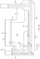
- the shroud support 314 is shown in the section view of FIG. 12 . As shown, the shroud support 314 may include a shroud support inlet 315.
- the shroud support inlet 315 may be a through-hole that extends radially through the inner ring 320 of the shroud support 314.
- the shroud assembly 310 may further include a baffle wall 317.
- the baffle wall 317 may be a relatively thin-walled structure that is fixedly attached to the shroud support 314 proximate the leading edge 311 of the shroud assembly 310.
- the baffle wall 317 may be spaced outwardly radially from the inner ring 320 as shown in FIG. 12 and may extend over and at least partially cover over the shroud support inlet 315.
- an upstream plenum 319 may be at least partly defined between the baffle wall 317 and the outer diameter surface of the inner ring 320 of the shroud support 314. Cooling air may be received within the plenum 319, and as will be discussed, the cooling air may flow downstream into the shroud support inlet 315 to provide a cooling effect.
- the shroud assembly 310 of FIGS. 12-14 may include the shroud segment 312.
- the shroud segment 312 may include the inner diameter surface 330, which opposes the tip of the blade of the rotor assembly 292. During operation, heat at the inner diameter surface 330 may transfer through the shroud segment 312 and other areas of the shroud assembly 310.
- the shroud segment 312 may include the internal cooling passage 346, which may be fluidly connected to the shroud support inlet 315 to receive a cooling fluid flow (airflow) for cooling the shroud segment 312.
- the internal cooling passage 346 may include at least two impingement apertures that are arranged in series in a downstream direction. As such, cooling air passing through one impingement aperture cools an inner surface of the passage 346, then flows downstream through the passage 346 through another impingement aperture for further cooling of another inner surface of the passage 346. Air within the internal cooling passage 346 then exits the shroud segment 312 and may flow to the core flow.
- shroud segment 312 may be strong, resilient, and robust due to a number of features that will be discussed. These features allow the shroud segment 312 to withstand thermally-driven mechanical effects (e.g., thermal expansion and resulting stresses, etc.) on the shroud segment 312 and/or other parts of the assembly 310.
- shroud segment 312 may include one or more features that improve its manufacturability as will be discussed in detail below.
- the shroud segment 312 may include an inner diameter wall 345.
- the inner diameter wall 345 may extend arcuately in the circumferential direction about the axis 180.
- the inner diameter wall 345 may define the inner diameter surface 330.
- the inner diameter wall 345 may define the trailing backside surface 321 and the forward backside surface 323.
- Both backside surfaces 321, 323 may face outwardly radially (i.e., in an opposite radial direction from the inner diameter surface 330).
- the backside surfaces 321, 323 may also define one or more boundaries of the internal cooling passage 346, and the internal cooling passage 346 may be configured for cooling the backside surfaces 321, 323.
- the shroud segment 312 may also include the leading edge rail 342 and the trailing edge rail 340 ( FIGS. 12 and 14 ).
- the leading edge rail 342 may extend outwardly along the radial axis 190 from the inner diameter wall 345, proximate the leading edge 311.
- the trailing edge rail 340 may extend outwardly from the inner diameter wall 345, proximate the trailing edge 313.
- the leading edge rail 342 and the trailing edge rail 340 may be fixedly attached to the shroud support 314.
- one or both of the rails 340, 342 may be attached to the shroud support 314 via a hook feature, a dovetail joint, and/or another type of connection.
- the shroud segment 312 may further include the first end 336 and the second end 338, which are spaced apart in the circumferential direction ( FIG. 13 ).
- the first end 336 may be disposed in an end-to-end arrangement with a neighboring shroud segment 351.
- the first end 336 may be coupled to the neighboring shroud segment 351.
- an intersegment seal 376 such as one or more feather seals, may be included within the opposing grooves 333 of the neighboring shroud segments 312, 351. Accordingly, air flow between the shroud segments 312, 351 may be affected by the seal 376 in a predetermined manner.
- the second end 338 may be similarly coupled to its neighboring shroud segment 359.
- the shroud segment 312 may further include a first end wall 364 and a second end wall 366.
- the second end wall 366 is shown in detail in FIG. 14 , and it will be appreciated that the first end wall 364 may be substantially similar.
- the first end wall 364 and the second end wall 366 may extend generally outward from the inner diameter wall 345.
- the second end wall 366 may lie within a plane that is substantially parallel to the radial axis 190, and the second end wall 366 may be spaced at a tangential distance 368 therefrom.
- the second end wall 366 may also be spaced apart at a tangential distance 371 from the second end 338.
- the first end wall 364 may be configured similar to the second end wall 366, but on the opposite side of the radial axis 190.
- the shroud segment 312 may also include an outer wall 373.
- the outer wall 373 may extend in the circumferential direction between the first end wall 364 and the second end wall 366 ( FIG. 13 ).
- the fluid inlet 348 may be a through hole that extends through the outer wall 373.
- the fluid inlet 348 may be fluidly connected to the shroud support inlet 315 via a sealing member 375.
- the sealing member 375 may be a hollow tube and may encircle the fluid inlet 348 and the shroud support inlet 315.
- the sealing member 375 may be a flexible, extendible, bellows-like seal, etc. that is configured to flex (lengthen and/or shorten) in the radial direction. Accordingly, the sealing member 375 may substantially hermetically seal the junction between the shroud support inlet 315 and the inlet 348 of the shroud segment 312.
- the shroud segment 312 may also include an aft wall 377.
- the aft wall 377 may have an L-shaped sectional profile with one end that is connected to the trailing edge rail 340 and an opposite outer end 349 that is connected to the outer wall 373.
- the aft wall 377 may also be spaced outwardly radially from the inner diameter wall 345.
- the aft wall 377 may be joined to the second end wall 366 in the circumferential direction. It will be appreciated that the aft wall 377 may be similarly joined to the first end wall 364.
- the shroud segment 312 may further include an intermediate wall 379.
- the intermediate wall 379 may project radially outward from the inner diameter wall 345.
- the intermediate wall 379 may also be disposed between and spaced apart along the longitudinal axis 180 from the leading edge rail 342 and the trailing edge rail 340.
- the intermediate wall 379 may extend between the first end wall 364 and the second end wall 366 in the circumferential direction.
- the shroud segment 312 may also include an intermediate diameter wall 383 ( FIG. 12 ).
- the intermediate diameter wall 383 may extend forward along the axis 180 from an outer radial end of the intermediate wall 379. Also, the intermediate diameter wall 383 may extend in the circumferential direction between the first end wall 364 and the second end wall 366. In some embodiments, the intermediate diameter wall 383 may be cantilevered over the inner diameter wall 345. More specifically, the intermediate wall 379 may support one axial end of the intermediate diameter wall 383 and other remaining portions may extend forward, decoupled from the inner diameter wall 345 at the forward and circumferential ends.
- the shroud segment 312 may include a forward wall 385.
- the forward wall 385 may extend generally outward radially from the intermediate diameter wall 383.
- the forward wall 385 may include an outer end 387 that is attached to the outer wall 373.
- the forward wall 385 may extend substantially parallel to the radial axis 190 ( FIG. 12 ).
- the forward wall 385 may extend in the circumferential direction between the first end wall 364 and the second end wall 366.
- the shroud segment 312 may further include a first inner end wall 389 and a second inner end wall 391 that are spaced apart in the circumferential direction.
- the first and second inner end walls 389, 391 may extend inwardly from the outer wall 373.
- the first inner end wall 389 may be disposed proximate the first end wall 364 and may be disposed substantially parallel to the first end wall 364.
- the second inner end wall 391 may be disposed proximate the second end wall 366 and may be substantially parallel to the second end wall 366.
- the shroud segment 312 may include a forward interior wall 393 and an aft interior wall 395.
- the forward and aft interior walls 393, 395 may extend radially inward from the outer wall 373, may turn axially toward the trailing edge 313, and may be connected at a junction 397.
- the forward interior wall 393 may be joined to both the first and second inner end walls 389, 391 in the circumferential direction.
- the aft interior wall 395 may be similarly joined to the first and second inner end walls 389, 391.
- the internal cooling passage 346 may be defined through the shroud segment 312 and may include the inlet 348.
- the internal cooling passage 346 may also include an inlet area 386.
- the inlet area 386 may be defined between the outer wall 373, the forward interior wall 393, the aft interior wall 395, the first inner end wall 389 and the second inner end wall 391.
- the internal cooling passage 346 may also include the first chamber 352.
- the first chamber 352 may be defined between the inner diameter wall 345, the aft wall 377, the forward interior wall 393, the intermediate wall 379, the wall 383, the forward wall 385, the first inner end wall 389, the first end wall 364, the second inner end wall 391, and the second end wall 366.
- the first chamber 352 includes the trailing backside surface 321.
- the internal cooling passage 346 may include the second chamber 354.
- the second chamber 354 may be defined between the inner diameter wall 345, the intermediate wall 379, the intermediate diameter wall 383, and the leading edge rail 342. As such, the second chamber 354 includes the forward backside surface 323. It is also noted that the intermediate diameter wall 383 divides the first chamber 352 from the second chamber 354.
- the internal cooling passage 346 additionally includes a plurality of the first impingement apertures 353, which fluidly connect the inlet area 386 and the first chamber 352. Some of the first impingement apertures 353 extend substantially in the radial direction through the forward interior wall 393 such that impingement air is directed radially toward the backside surface 321. Other first impingement apertures 353 extend through the junction 397 and are directed substantially rearward such that impingement air is directed rearward against the inner surface of the trailing edge rail 340.
- the internal cooling passage 346 may include a plurality of the second impingement apertures 355, which fluidly connect the first chamber 352 and the second chamber 354.
- the second impingement apertures 355 may extend radially through the intermediate diameter wall 383 such that impingement air is directed radially toward the backside surface 323.
- the first and/or second impingement apertures 353, 355 may include tapered upstream ends 399.
- the tapered upstream end 399 may be a frusto-conic taper, such as a chamfer. Accordingly, the upstream end 399 may be wider than the opposing downstream end to improve fluid flow through the internal cooling passage 346. More specifically, the tapered upstream ends 399 may reduce loss as air enters the impingement apertures 353, 355 and/or may provide a stronger jet of air for improved cooling effectiveness.
- the tapered upstream ends 399 may reduce and/or eliminate flow separation and associated recirculation of the flow entering the impingement apertures 353, 355.
- the shroud segment 312 may include one or more internal projections 398.
- the internal projection 398 may be a bump, a post, a nub, or other small projection that is disposed proximate one of the impingement apertures 353, 355.
- the internal projection 398 is shown proximate one of the first impingement apertures 353.
- other impingement apertures 353, 355 may include a respective projection 398 as well.
- the internal projections 398 may be configured for directing airflow within the passage 346. In some embodiments, the projections 398 may be positioned to re-direct air that would otherwise disrupt the jets of air emitted from the impingement apertures 353, 355.
- the projection 398 may be disposed proximate the aperture 353 and aligned therewith. As such, air within the first chamber 352 may flow around the projection 398, redirected away from the downstream end of the impingement apertures 353, and toward the second impingement apertures 355.
- the shroud segment 312 may include the outlet 358.
- the outlet 358 may be fluidly connected to the second chamber 354. As shown in FIGS. 12 and 14 , the outlet 358 may be defined in the axial direction between the leading edge rail 342 and the forward wall 385. This space may extend continuously in the circumferential direct to define a circumferential slot. Moreover, as shown in FIG. 14 , the outlet 358 may be open at the circumferential ends of the shroud segment 312 as well.
- Air within the upstream plenum 319 may flow in the downstream direction through the shroud support inlet 315 and into the inlet 348 of the shroud segment 312. Then, air within the inlet area 386 may flow through the first impingement apertures 353 and may be jetted toward the trailing backside surface 321 and the trailing edge rail 340 for cooling. The air may be redirected forward within the first chamber 352, toward the second impingement apertures 355. This air may flow through the second impingement apertures 355 and may be jetted toward the forward backside surface 323 for cooling. Then, the air may flow through the outlet 358 and into the outlet chamber 370 ( FIG. 14 ) (i.e., the "backflow cavity"). Finally, this air may re-enter the core flow path.
- the shroud segment 312 may be a unitary, one-piece body.
- the shroud segment 312 may be assembled from two or more members that are independently formed, then attached together.
- the members may cooperatively define the chambers 352, 354 as well as the impingement apertures 353, 355.
- the shroud segment 312 may include a first member 302 and a second member 304.
- the first and second members 302, 304 may be relatively thin-walled, hollow bodies.
- the first member 302 may be a unitary one-piece member that includes the outer wall 373, the forward interior wall 393, the aft interior wall 395, the first inner end wall 389, and the second inner end wall 391. This first member 302 may be relatively hollow and box-like and may be nested within the second member 304. The first member 302 may also include the first impingement apertures 353.
- the second member 304 may be a unitary one-piece member that includes the trailing edge rail 340, the forward edge rail 342, the inner diameter wall 345, the aft wall 377, the intermediate wall 379, the intermediate diameter wall 383, the forward wall 385, the first end wall 364, and the second end wall 366.
- the trailing edge rail 340, the aft wall 377, the intermediate wall 379, the intermediate diameter wall 383, the forward wall 385, the inner diameter wall 345, the first end wall 364, and the second end wall 366 may cooperatively define a hollow and box-like structure that receives the first member 302.
- first and second members 302, 304 may cooperatively define the internal cooling passage 346.
- the first member 302 may define the inlet 348 as well as the inlet area 386 of the internal cooling passage 346.
- the first chamber 352 may be defined in the space between the first member 302 and the second member 304.
- the second chamber 354 may be defined by the second member 304, independent of the first member 302.
- the second member 304 may also define the outlet 358 of the internal cooling passage 346.
- the first member 302 and the second member 304 may be manufactured independently.
- the first and second members 302, 304 may be separately formed using casting operations, using additive manufacturing techniques, etc. Once formed, the first member 302 and the second member 304 may be fixedly connected and hermetically sealed together.
- the first member 302 and the second member 304 may be attached together at a sealed joint 306.
- the sealed joint 306 may attach the underside of the outer wall 373 to the outer end 349 of the aft wall 377 and the outer end 387 of the forward wall 385 ( FIG. 12 ) as well as the outer ends of the first and second end walls 364, 366 ( FIG. 13 ) so as to seal off the first chamber 352.
- the joint 306 may extend continuously and may have a generally rectangular shape when viewed from the radial perspective.
- the sealed joint 306 may be a substantially planar joint. As indicated by the line 303 in FIGS. 12 and 13 , the sealed joint 306 may lie within a plane that is tangential to an imaginary circle, which is substantially centered on the longitudinal axis 180 and that has a radius substantially perpendicular to the axis 180.
- the interfacing surfaces of the first member 302 and the second member 304 for the joint 306 may be planar as well. Before attachment, the first member 302 and the second member 304 may define opposing planar surfaces, and these surfaces may be abutted and then attached together. Because the joint 306 is substantially planar, manufacture of the shroud segment 312 may be facilitated. Also, the hermetic seal between the first and second members 302, 304 may be ensured due to the planar configuration of the joint 306.
- first and second members 302, 304 may be connected at the joint 306 via a transient liquid phase (TLP) joining process.
- TLP transient liquid phase
- a thin layer of prepared braze foil may be placed between the first member 302 and the second member 304, and the members 302, 304 may be heated while a compression load is applied. Material may diffuse between the opposing surfaces to connect and join the first and second members 302, 304.
- first and second members 302, 304 may be diffusion bonded together.
- the joint 306 may also be a brazed joint or a welded joint.
- first and second members 302, 304 may be joined and hermetically sealed using fasteners and one or more gaskets.
- the joint 306 is radially spaced apart at a distance 308 from the inner diameter surface 330. Accordingly, heat from the inner diameter surface 330 may distribute through the shroud segment 312 without detrimentally affecting the joint 306. Moreover, the shroud segment 312 may distribute thermal loads relatively evenly, making the shroud segment 312 more robust.
- the first end wall 364 and second end wall 366 may extend outward a substantial distance. Accordingly, the first end wall 364 and the second end wall 366 may be more flexible to withstand the effects of thermal expansion. Again, this feature allows the shroud segment 312 to be relatively robust.
Abstract
Description
- This application claims priority to
U.S. Provisional Patent Application Serial No. 62/521,000, filed June 16, 2017 - This invention was made with Government support under W58RGZ-16-C-0046 awarded by the U.S. Army. The Government has certain rights in the invention.
- The present disclosure generally relates to a turbine tip shroud assembly and, more particularly, to a turbine tip shroud assembly with plural shroud segments having internal cooling passages.
- Gas turbine engines are generally used in a wide range of applications, such as aircraft engines and auxiliary power units. In a gas turbine engine, air is compressed in a compressor, mixed with fuel, and ignited in a combustor to generate hot combustion gases, which flow downstream into a turbine section. In a typical configuration, the turbine section includes airfoils, such as stator vanes and rotor blades, disposed in an alternating sequence along the axial length of a generally annular hot gas flow path. The rotor blades are mounted at the periphery of one or more rotor disks that are coupled in turn to a main engine shaft. Hot combustion gases are delivered from the engine combustor to the annular hot gas flow path, thus resulting in rotary driving of the rotor disks to provide an engine output.
- Due to the high temperatures in many gas turbine engine applications, it is desirable to regulate the operating temperature of certain engine components, particularly those within the mainstream hot gas flow path in order to prevent overheating and potential mechanical issues attributable thereto. For example, it is desirable to cool the shroud in the turbine section (i.e., the turbine shroud) to prevent or reduce oxidation, thermo-mechanical fatigue, and/or other adverse impacts. However, given the high temperature of engine operation, cooling remains a challenge.
- Accordingly, it is desirable to provide gas turbine engines with improved turbine shroud cooling. Furthermore, other desirable features and characteristics of the present disclosure will become apparent from the subsequent detailed description and the appended claims, taken in conjunction with the accompanying drawings and this background discussion.
- In one embodiment, a shroud assembly is disclosed for a gas turbine engine. The shroud assembly is configured to receive a cooling fluid flow. The shroud assembly includes a shroud support that extends arcuately about an axis. The shroud assembly also includes a plurality of shroud segments that are attached to the shroud support and that are arranged annularly about the axis at different circumferential positions with respect to the axis. At least one of the plurality of shroud segments includes an internal cooling passage that extends through the shroud segment. The shroud segment also includes at least one inlet for receiving and directing the cooling fluid flow into the internal cooling passage. Moreover, the shroud segment includes at least one outlet for outputting the cooling fluid flow from the internal cooling passage to a backflow cavity of the shroud assembly. The internal cooling passage is substantially hermetically sealed from the at least one inlet to the at least one outlet.
- In another embodiment, a method of manufacturing a shroud assembly that is configured to receive a cooling fluid flow is disclosed. The method includes providing a shroud support that extends arcuately about an axis. The shroud support includes a shroud support inlet. The method also includes attaching a plurality of shroud segments to the shroud support at different circumferential positions about the axis to arrange the plurality of shroud segments annularly about the axis. At least one of the plurality of shroud segments includes an internal cooling passage that extends therethrough from an inlet to at least one outlet. Furthermore, the method includes fluidly connecting the inlet of the internal cooling passage to the shroud support inlet. The internal cooling passage is substantially hermetically sealed from the inlet to the at least one outlet. The at least one outlet is fluidly connected to a backflow cavity of the shroud assembly.
- Furthermore, a gas turbine engine is disclosed that includes a rotor assembly of a turbine section. The rotor assembly includes a turbine blade. The gas turbine engine also includes a shroud assembly of the turbine section configured to receive a cooling fluid flow. The shroud assembly includes a shroud support that extends arcuately about an axis. The shroud assembly also includes a plurality of shroud segments that are attached to the shroud support and that are arranged annularly about the axis at different circumferential positions with respect to the axis. At least one of the plurality of shroud segments includes an inner diameter surface configured to oppose the turbine blade as the turbine blade rotates about the axis. The shroud segment also includes an internal cooling passage that extends through the at least one of the plurality of shroud segments. The shroud segment includes at least one inlet for receiving and directing the cooling fluid flow into the internal cooling passage. Furthermore, the shroud segment includes at least one outlet for outputting the cooling fluid flow from the internal cooling passage. The internal cooling passage is substantially hermetically sealed from the at least one inlet to the at least one outlet. The internal cooling passage includes a first chamber that is partly defined by a first backside surface, which faces opposite the inner diameter surface. The internal cooling passage includes a second chamber that is partly defined by a second backside surface, which faces opposite the inner diameter surface. The internal cooling passage includes a first impingement aperture directed into the first chamber generally toward the first backside surface. The internal cooling passage includes a second impingement aperture directed into the second chamber generally toward the second backside surface. The internal cooling passage is configured to direct the cooling fluid flow from the first impingement aperture into the first chamber and downstream into the second chamber via the second impingement aperture.
- The present disclosure will hereinafter be described in conjunction with the following drawing figures, wherein like numerals denote like elements, and wherein:
-
FIG. 1 is a schematic side view of a gas turbine engine according to exemplary embodiments of the present disclosure; -
FIG. 2 is an isometric view of a turbine shroud assembly of the gas turbine engine ofFIG. 1 according to example embodiments of the present disclosure; -
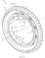
FIG. 3 is an isometric view of a portion of the turbine shroud assembly ofFIG. 2 , which includes a single shroud segment according to example embodiments of the present disclosure; -
FIG. 4 is a section view of the turbine shroud assembly taken along the line 4-4 ofFIG. 3 ; -
FIG. 5 is an isometric view of the shroud segment ofFIG. 3 ; -
FIG. 6 is a top view of the shroud segment ofFIG. 5 ; -
FIG. 7 is an end view of the shroud segment ofFIG. 5 ; -
FIG. 8 is a section view of the shroud segment taken along the line 8-8 ofFIG. 6 ; -
FIG. 9 is a section view of the shroud segment taken along the line 9-9 ofFIG. 6 ; -
FIG. 10 is a section view of the shroud segment taken along the line 10-10 ofFIG. 6 ; -
FIG. 11 is a section view of an inter-segment joint of the turbine shroud assembly taken along the line 11-11 ofFIG. 2 ; -
FIG. 12 is a section view of the turbine shroud assembly taken along the longitudinal axis according to additional embodiments of the present disclosure; -
FIG. 13 is a section view of the shroud segment of the shroud assembly taken along the line 13-13 ofFIG. 12 ; and -
FIG. 14 is a circumferential end view of the shroud segment ofFIG. 12 . - The following detailed description is merely exemplary in nature and is not intended to limit the present disclosure or the application and uses of the present disclosure. Furthermore, there is no intention to be bound by any theory presented in the preceding background or the following detailed description.
- Broadly, exemplary embodiments disclosed herein include gas turbine engines with one or more turbine shroud assemblies having improved cooling characteristics. Methods of manufacturing the turbine shroud assembly are also disclosed. In particular, exemplary embodiments include a turbine shroud assembly with internal impingement cooling passages configured for internally cooling components of the shroud assembly.
- A shroud assembly is disclosed according to example embodiments, wherein the assembly includes a plurality of shroud segments that are independently attached and substantially sealed to a shroud support case. As such, the shroud segments and the shroud support case cooperate to define cooling flow passages for cooling the shroud segments and for directing the cooling fluid (e.g., air) to flow back into the core flow. The shroud segments may include internal cooling passages as well. The internal cooling passages may be airtight except for the one or more defined inlets and the one or more defined outlets of the shroud segment. In some embodiments, the internal cooling passages may impinge two or more times in succession. In other words, the shroud segment may include an internal cooling passage with at least two impingement apertures arranged in series with respect to the flow direction of the passage. Accordingly, the cooling effectiveness for a given amount of cooling flow is increased substantially.
- Other details of the present disclosure will be discussed below with reference to the drawings. It will be appreciated that the embodiments of the present disclosure shown in the drawings are examples, and that the embodiments may vary from those shown without departing from the scope of the present disclosure.
-
FIG. 1 is a cross-sectional view of agas turbine engine 100 according to an exemplary embodiment. AlthoughFIG. 1 depicts a turbofan engine, in general, exemplary embodiments discussed herein may be applicable to another type of engine without departing from the scope of the present disclosure. Thegas turbine engine 100 may form part of, for example, an auxiliary power unit for an aircraft or a propulsion system for an aircraft. However, thegas turbine engine 100 may be included on another vehicle without departing from the scope of the present disclosure. Instead of being included on a vehicle, thegas turbine engine 100 may also be supported by a stationary mount in some embodiments. - The
gas turbine engine 100 has an overall construction and operation that is generally understood by persons skilled in the art. Thegas turbine engine 100 may be disposed in anengine case 101 and may include afan section 120, acompressor section 130, acombustion section 140, aturbine section 150, and anexhaust section 160, which are arranged sequentially along alongitudinal axis 180. - For reference purposes, the
gas turbine engine 100 will be discussed with reference to a radial coordinate system. Accordingly, as used herein, the term "axial" refers to a direction along thelongitudinal axis 180. Aradial axis 190 is also included inFIG. 1 for reference purposes, and the term "radial" as used herein refers to a direction along theradial axis 190 or along another line extending radially with respect to theaxis 180. Moreover, the term "circumferential" as used herein refers to a direction extending around or about theaxis 180, at a particular radial distance from theaxis 180. - The
fan section 120 may include a fan, which draws in and accelerates air. A fraction of the accelerated air from thefan section 120 is directed through abypass section 170 to provide a forward thrust. The remaining fraction of air exhausted from the fan is directed into thecompressor section 130. - The
compressor section 130 may include a series of compressors that raise the pressure of the air directed into it from thefan section 120. The compressors may direct the compressed air into thecombustion section 140. - In the
combustion section 140, the high pressure air is mixed with fuel, which is combusted. The post-combustion air is then directed into theturbine section 150. - The
turbine section 150 may include a series ofrotor assemblies 192 andstator assemblies 194, both of which are represented schematically inFIG. 1 . Theturbine section 150 may also include one ormore shroud assemblies 210, which are also represented schematically. Theshroud assembly 210 may generally encircle arespective rotor assembly 192. Theshroud assembly 210 may encircle the tips of blades of therotor assembly 192 and, thus, may be referred to as a turbine tip shroud assembly. - During operation, post-combustion air from the
combustion section 140 may be directed by thestator assembly 194 toward blades included in therotor assembly 192. The post-conduction air impinges upon the rotor blades, thereby driving and rotating therotor assembly 192 relative to theturbine shroud assembly 210, causing therotor assembly 192 to rotate a main engine shaft for energy extraction. The flow may be directed through a propulsion nozzle disposed in theexhaust section 160 to provide additional forward thrust. - To allow the
turbine section 150 to operate at desirable elevated temperatures, certain components are cooled. For example, in some embodiments, theshroud assembly 210 may include one or more features of the present disclosure that promote cooling. Manufacturing techniques of the present disclosure are also discussed below for providing theshroud assembly 210 with the cooling features of the present disclosure. - Referring now to
FIGS. 2 ,3 , and4 , theturbine shroud assembly 210 is shown in detail according to example embodiments. Theturbine shroud assembly 210 may be substantially annular and may extend continuously in a circumferential direction about the longitudinal axis 180 (FIG. 2 ). Theturbine shroud assembly 210 includes aleading edge 211 and a trailingedge 213, which are separated at a distance along thelongitudinal axis 180. Theleading edge 211 faces generally in a forward direction along theaxis 180, and the trailingedge 213 faces generally in a rearward direction along theaxis 180. - As shown in
FIG. 2 , theturbine shroud assembly 210 may include ashroud support 214. Theshroud support 214 may be a substantially unitary, one-piece, annular component with at least a portion that extends continuously about theaxis 180. Theshroud support 214 may include anouter diameter portion 216 and aninner diameter portion 218. Theouter diameter portion 216 may be fixedly attached to the engine case 101 (FIG. 1 ) or other surrounding support structure. Theinner diameter portion 218 may include aninner ring 220. A circumferential segment of theinner ring 220 is shown inFIG. 3 and is shown in the section view ofFIG. 4 . As shown inFIGS. 3 and4 , theinner ring 220 may include aninner diameter surface 222. Theinner ring 220 may also include asupport arm 224, which attaches theinner ring 220 to theouter diameter portion 216. Theshroud support 214 may further include a trailingedge member 225 and a leading edge member 226 (FIG. 3 ). As shown, the trailingedge member 225 and theleading edge member 226 may extend radially inward toward thelongitudinal axis 180 from theinner ring 220. The trailingedge member 225 and theleading edge member 226 may be spaced apart along theaxis 180. - Additionally, as shown in
FIG. 2 , theturbine shroud assembly 210 may include a plurality ofshroud segments 212 that are arranged annularly about theaxis 180. Theshroud segments 212 may be spaced circumferentially about theinner diameter surface 222 of theinner ring 220. Anindividual shroud segment 212 from a particular circumferential position (with respect to the axis 180) is shown inFIGS. 3-6 in detail. Theshroud segment 212 is attached to a portion of theinner ring 220 inFIGS. 3 and4 . Theindividual shroud segment 212 is shown in isolation inFIGS. 5 and6 . - In some embodiments, the
shroud segment 212 may be a monolithic, unitary, one-piece member. In other embodiments, theshroud segment 212 may be constructed from multiple pieces that are attached. It will be appreciated that theshroud segment 212 ofFIGS. 4-6 may be representative of other shroud segments at different circumferential positions on theshroud support 214. - As shown in
FIGS. 4 ,5 and6 , theshroud segment 212 may include anouter diameter surface 228 and an oppositeinner diameter surface 230. Theshroud segment 212 may further include anupstream face 232 and an oppositedownstream face 234, which are spaced apart along theaxis 180. Theshroud segment 212 may also include afirst end 236 and asecond end 238. Theshroud segment 212 may be elongate and slightly arcuate in the circumferential direction between thefirst end 236 and thesecond end 238. Theshroud segment 212 may further include a trailingedge rail 240 and aleading edge rail 242. The trailingedge rail 240 and theleading edge rail 242 may project radially outward from theouter diameter surface 228 and away from theaxis 180. Theouter diameter surface 228 may also include afirst end recess 229 proximate thefirst end 236 and asecond end recess 231 proximate thesecond end 238. - The
first end 236 and/or thesecond end 238 may include an arrangement of one ormore grooves 233. As shown inFIG. 7 , thegrooves 233 may include afirst groove 235 that extends axially along theshroud segment 212, continuously from theupstream face 232 to thedownstream face 234. Thegrooves 233 may also include asecond groove 237 that extends radially along theleading edge rail 242 and that curves to intersect thefirst groove 235. Thegrooves 233 may further include athird groove 239 that extends radially along the trailingedge rail 240 and that curves to intersect thefirst groove 235. Moreover, thegrooves 233 may include afourth groove 241 that extends diagonally between and that intersects both thefirst groove 235 and thethird groove 239. - As shown in
FIGS. 5 and6 , theshroud segment 212 may further include aprojection 244. Theprojection 244 may be annular and may project radially away from theouter diameter surface 228. In some embodiments, theprojection 244 may be disposed in a central region of theouter diameter surface 228, substantially centered axially between theupstream face 232 and thedownstream face 234 and/or substantially centered circumferentially between thefirst end 236 and thesecond end 238. Theprojection 244 may be hollow, and the inner diameter of theprojection 244 may be threaded in some embodiments. - The
shroud segment 212 may include at least oneinternal cooling passage 246 as shown inFIGS. 8, 9 , and10 . As shown inFIG. 8 , theprojection 244 may define aninlet 248 of theinternal cooling passage 246. - The
passage 246 of theshroud segment 212 may include afirst chamber 250 and asecond chamber 252. The first andsecond chambers axis 180 and that extends substantially parallel to theaxis 180. Thefirst chamber 250 and thesecond chamber 252 may extend in the circumferential direction as well. The first andsecond chambers edge 213 and may be overlapped in the radial direction as shown. Thefirst chamber 250 may be disposed outboard radially with respect to the second chamber 252 (i.e., thesecond chamber 252 may be disposed closer to theaxis 180 in the radial direction as compared to the first chamber 250). Thesecond chamber 252 may be partly defined by a trailingbackside surface 221 of the shroud segment 212 (i.e., the surface opposite theinner diameter surface 230 proximate the trailing edge 213). - The first and
second chambers first impingement apertures 253. Thefirst impingement apertures 253 may extend radially through an internal wall separating the first andsecond chambers - The
passage 246 of theshroud segment 212 may further include athird chamber 254 and afourth chamber 256 as shown inFIGS. 9 and10 . The third andfourth chambers axis 180 and that extends substantially parallel to theaxis 180. Thethird chamber 254 and thefourth chamber 256 may extend in the circumferential direction as well. Thethird chamber 254 and thefourth chamber 256 may be disposed proximate theleading edge 211 and may be overlapped in the radial direction as shown. Thethird chamber 254 may be disposed outboard radially with respect to thefourth chamber 256. Thefourth chamber 256 may be defined by aforward backside surface 223 of the shroud segment 212 (i.e., the surface opposite theinner diameter surface 230 proximate the leading edge 211). - The
third chamber 254 may be fluidly connected to thesecond chamber 252 via anintermediate opening 227 as shown inFIGS. 9 and10 . Theintermediate opening 227 may be relatively wide so as to facilitate fluid flow from thesecond chamber 252 to thethird chamber 254. - Also, the
third chamber 254 may be fluidly connected to thefourth chamber 256 by one or moresecond impingement apertures 255. The second impingement apertures may extend radially through an internal wall separating the third andfourth chambers - In some embodiments, there may be at least one third impingement aperture 243 (
FIG. 8 ). Thethird impingement aperture 243 may fluidly connect thefirst chamber 250 and thefourth chamber 256. - Moreover, the
shroud segment 212 may define one ormore outlets 258 of the internal cooling passage 246 (FIGS. 6 and10 ). In the illustrated embodiment, there are a plurality ofoutlets 258. As shown, theoutlets 258 may be circular through-holes that extend radially from thefourth chamber 256 and through theouter diameter surface 228. In some embodiments, theoutlets 258 may be disposed proximate the leading edge rail 242 (FIG. 10 ), and theoutlets 258 may be spaced apart from each other in the circumferential direction (FIG. 6 ). - As shown in
FIGS. 2 ,3 , and4 , theshroud segments 212 may be fixedly attached to theshroud support 214. Theshroud segments 212 may be independently and individually attached to theshroud support 214. Also, theshroud segments 212 may be substantially sealed (e.g., substantially hermetically sealed) to theshroud support 214. As such, theshroud segment 212 and theshroud support 214 cooperate to define an airflow path, and theinlet 248 and theoutlets 258 may define part of this airflow path as will be discussed in detail below. - In some embodiments, the
shroud segment 212 may be fixed to theshroud support 214 via afastener 260. In some embodiments, thefastener 260 may be theonly fastener 260 used for the attachment of theshroud segment 212 and theshroud support 214. Thefastener 260 may be hollow and tubular in some embodiments. Additionally, in some embodiments, thefastener 260 may extend radially through theshroud support 214 to be received within theprojection 244. In some embodiments, thefastener 260 may threadably engage the inner diameter of theprojection 244. Accordingly, the interior of thefastener 260 may be fluidly connected to theinlet 248 of theinternal cooling passages 246. Also, thefastener 260 may include anenlarged head 262 that engages the outer diameter surface of thering 220. Thefastener 260 may also include one or more support structures that support thefastener 260, allow for thermal expansion, etc. Accordingly, thefastener 260 may press the outer diameter portions of theshroud segment 212 to theinner diameter surface 222 of thering 220 and apply a force that is directed substantially in the radial direction. - When attached (
FIG. 4 ), the leadingedge rail 242 of theshroud segment 212 may be disposed proximate theleading edge member 226 of theshroud support 214. Theupstream face 232 may be disposed adjacent the opposing surface of theleading edge member 226. Also, the trailingedge rail 240 of theshroud segment 212 may be disposed proximate the trailingedge member 225 of theshroud support 214. Anaxial retention member 257 may be included proximate the trailingedge rail 240. Theaxial retention member 257 may abut the trailingedge 240 and apply an axial load. Accordingly, theaxial retention member 257 may substantially seal against therail 240 due to the axial load. In some embodiments, theaxial retention member 257 may include or comprise a so-called brush seal. A trailingedge space 281 may be defined between theaxial retention member 257, the trailingedge member 225, theinner diameter surface 222 of thering 220, and theouter diameter surface 228 of theshroud segment 212. - Moreover, the
shroud segment 212 may cooperate with theshroud support 214 to define anoutlet chamber 270. Theoutlet chamber 270 may be referred to as a "backflow cavity," which is disposed upstream from the core flow path. Specifically, in some embodiments, theouter diameter surface 228 and theleading edge rail 242 of theshroud segment 212 may cooperate with theinner diameter surface 222 and the trailingedge member 225 of theshroud support 214 to define theoutlet chamber 270. Theoutlet chamber 270 may be generally arcuate in shape and may extend in the circumferential direction toward thefirst end 236 and thesecond end 238 of theshroud segment 212. - The
shroud assembly 210 may further include one or more sealing members that seal gap(s) between plural components. In some embodiments, the sealing members may be arranged for directing flow in a predetermined manner. - For example, as shown in
FIG. 4 , theshroud assembly 210 may include afirst sealing member 272 that is disposed between thehead 262 of the fastener and the outer diameter surface of thering 220 of theshroud support 214. Thefirst sealing member 272 may be a flexible metal seal in some embodiments. - The
shroud assembly 210 may further include asecond sealing member 274. Thesecond sealing member 274 may be disposed within the trailingedge space 281, between the trailingedge rail 240 of theshroud segment 212 and the trailingedge member 225 of theshroud support 214. In some embodiments, thesecond sealing member 274 may be a flexible metal seal. Thesecond sealing member 274 may also partly define theoutlet chamber 270 and may be configured as a fluid boundary proximate the trailingedge 213. - The
shroud assembly 210 may also include other sealing members, such as a sealing compound that is included at the threaded attachment of thefastener 260 and theprojection 244. Other sealing members may also be included in some embodiments. Accordingly, theshroud segment 212 may be substantially hermetically sealed to theshroud support 214. - Furthermore, as shown in
FIG. 3 , thefirst end 236 and/or thesecond end 238 of theshroud segment 212 may include aninter-segment sealing member 276. Theinter-segment sealing member 276 may include one or more so-called feather seals. Theinter-segment sealing member 276 on thesecond end 238 is shown, and it will be appreciated that thefirst end 236 may include a similar sealing member. In some embodiments, theinter-segment sealing member 276 may include athird seal 278 and afourth seal 280. Thethird seal 278 and thefourth seal 280 may be received in the grooves 233 (FIG. 7 ) of thesecond end 238 as shown inFIG. 3 , and it will be appreciated that the third andfourth seals grooves 233 of a neighboring (opposing)shroud segment 212 within theshroud assembly 210. As shown inFIG. 11 , thethird seal 278 may be received within thefirst groove 235 and thethird groove 239. Thefourth seal 280 may be received within thesecond groove 237, within portions of thefirst groove 235, within thefourth groove 241, and within portions of thethird groove 239. Areas of thethird seal 278 and thefourth seal 280 may overlap and may be layered in contact with each other. For example, as shown inFIG. 11 , thethird seal 278 and thefourth seal 280 may layer over each other within thefirst groove 235 and proximate the terminal end of thethird groove 239. At other areas, the third andfourth seals third seal 278 may be spaced from thefourth seal 280 to define anintermediate cavity 282 therebetween. - During operation of the
gas turbine engine 100, tips of the blades on the rotor assembly 192 (FIGS. 1 and11 ) rotate relative to theinner diameter surface 230 of theshroud segment 212. Theshroud segments 212 may heat up to relatively high temperatures. To regulate the temperature of theshroud segments 212, a cooling gas flow (e.g., air diverted from the core flow of theengine 100 upstream of the combustion section 140) may be directed through thefastener 260, into theinlet 248 of theinternal cooling passage 246. The flow may be directed into thefirst chamber 250, through thefirst impingement apertures 253, and into thesecond chamber 252. Flow from thefirst impingement apertures 253 may be directed toward the trailingbackside surface 221 for cooling theshroud segment 212. Then, the flow may be directed forward (i.e., re-directed) along theaxis 180 into the third chamber 254 (FIG. 9 ). The flow may be directed, through thesecond impingement apertures 255 from thethird chamber 254 to thefourth chamber 256. Flow from thesecond impingement apertures 255 may be directed toward theforward backside surface 223 for further cooling of theshroud segment 212. The fluid flow may exit theshroud segment 212 via theoutlets 258. Additionally, some of the cooling fluid may flow from theinlet 248, through the third impingement aperture 243 (FIG. 8 ), to thefourth chamber 256, and out theoutlets 258. - The
internal cooling passages 246 may be defined within theshroud segments 212 such that the mass flow at theinlet 248 is be substantially equal to the mass flow at theoutlets 258. In other words, theinternal cooling passage 246 may be sealed along its flow path (from theinlet 248 to the outlets 258), and there may be no leakage path for fluid in thecooling passages 246. The flow may then flow back into the core flow path of theengine 100 through one or more gaps. For example, the cooling gas may flow axially into the core flow and/or circumferentially into the inter-segment joints between neighboring pairs of theshroud segments 212. Ultimately, the cooling gas may flow radially inward to return to the core flow path. - This flow of air may provide a cooling effect to the
shroud segment 212, thereby improving efficiency and effectiveness of thegas turbine engine 100. As discussed above, eachshroud segment 212 may be constrained and sealed individually to theshroud support 214. Also, substantially all cooling flow impinges the backside of theshroud segment 212 multiple times (e.g., twice) in succession. As such, for a given amount of cooling mass flow, impingement is multiplied (e.g., by two). Thus, impingement velocities may be higher, and cooling effectiveness may be increased. - Additionally, as discussed above, the
shroud assembly 210 at the inter-segment joints may improve flow characteristics. The arrangement of the third andfourth seals 278, 280 (FIG. 11 ) may define theintermediate cavity 282 proximate the trailingedge 213 and between theoutlet chamber 270 and thecore flow path 284. Also, the trailingedge space 281 may be disposed proximate the trailingedge 213. This may cause multiple (e.g., two) pressure drops along theaxis 180 between theoutlet chamber 270 and thecore flow path 284. This dual-series pressure drop reduces inter-segmental leakage at the trailingedge 213, wherein the static pressure of the flow path is lowest. - The
shroud segments 212 and other features of theshroud assembly 210 may be manufactured in a variety of ways without departing from the scope of the present disclosure. For example, theshroud segments 212 may be formed using multiple parts that are bonded together, that are inseparable, and/or that are integrally connected (e.g., via a brazing, laser welding, diffusion bonding, or other manufacturing process). In additional embodiments, theshroud segments 212 may be made from a single part produced, for example, by investment casting or additive manufacturing processes. In further embodiments, a casting core may be formed using an additive manufacturing technique, and then the casting core may be used to form features of the shroud segment 212 (e.g., ceramic stereo-lithography). Furthermore, in some embodiments, features of thesegments 212 may be machined using turning, milling, grinding, electrical discharge machining (EDM), or other machining operations. - Referring now to
FIGS. 12-14 , theshroud assembly 310 is represented according to additional embodiments of the present disclosure. Theshroud assembly 310 may include features that are discussed above in relation toFIGS. 1-11 . Components that correspond to those ofFIGS. 1-11 are indicated with corresponding reference numbers increased by 100. Additional features are discussed below. - The
shroud support 314 is shown in the section view ofFIG. 12 . As shown, theshroud support 314 may include ashroud support inlet 315. Theshroud support inlet 315 may be a through-hole that extends radially through theinner ring 320 of theshroud support 314. - The
shroud assembly 310 may further include abaffle wall 317. Thebaffle wall 317 may be a relatively thin-walled structure that is fixedly attached to theshroud support 314 proximate theleading edge 311 of theshroud assembly 310. Thebaffle wall 317 may be spaced outwardly radially from theinner ring 320 as shown inFIG. 12 and may extend over and at least partially cover over theshroud support inlet 315. Accordingly, in some embodiments, anupstream plenum 319 may be at least partly defined between thebaffle wall 317 and the outer diameter surface of theinner ring 320 of theshroud support 314. Cooling air may be received within theplenum 319, and as will be discussed, the cooling air may flow downstream into theshroud support inlet 315 to provide a cooling effect. - Like the embodiment of
FIG. 2 , theshroud assembly 310 ofFIGS. 12-14 may include theshroud segment 312. Theshroud segment 312 may include theinner diameter surface 330, which opposes the tip of the blade of therotor assembly 292. During operation, heat at theinner diameter surface 330 may transfer through theshroud segment 312 and other areas of theshroud assembly 310. However, theshroud segment 312 may include theinternal cooling passage 346, which may be fluidly connected to theshroud support inlet 315 to receive a cooling fluid flow (airflow) for cooling theshroud segment 312. - Like the embodiments discussed above, the
internal cooling passage 346 may include at least two impingement apertures that are arranged in series in a downstream direction. As such, cooling air passing through one impingement aperture cools an inner surface of thepassage 346, then flows downstream through thepassage 346 through another impingement aperture for further cooling of another inner surface of thepassage 346. Air within theinternal cooling passage 346 then exits theshroud segment 312 and may flow to the core flow. These configurations provide theshroud assembly 310 with efficient and effective cooling for improved operation of the gas turbine engine. - Moreover, the
shroud segment 312 may be strong, resilient, and robust due to a number of features that will be discussed. These features allow theshroud segment 312 to withstand thermally-driven mechanical effects (e.g., thermal expansion and resulting stresses, etc.) on theshroud segment 312 and/or other parts of theassembly 310. In addition, theshroud segment 312 may include one or more features that improve its manufacturability as will be discussed in detail below. - The
shroud segment 312 may include aninner diameter wall 345. Theinner diameter wall 345 may extend arcuately in the circumferential direction about theaxis 180. Theinner diameter wall 345 may define theinner diameter surface 330. Also, theinner diameter wall 345 may define the trailingbackside surface 321 and theforward backside surface 323. Both backside surfaces 321, 323 may face outwardly radially (i.e., in an opposite radial direction from the inner diameter surface 330). The backside surfaces 321, 323 may also define one or more boundaries of theinternal cooling passage 346, and theinternal cooling passage 346 may be configured for cooling the backside surfaces 321, 323. - The
shroud segment 312 may also include theleading edge rail 342 and the trailing edge rail 340 (FIGS. 12 and14 ). Theleading edge rail 342 may extend outwardly along theradial axis 190 from theinner diameter wall 345, proximate theleading edge 311. The trailingedge rail 340 may extend outwardly from theinner diameter wall 345, proximate the trailingedge 313. Theleading edge rail 342 and the trailingedge rail 340 may be fixedly attached to theshroud support 314. In some embodiments, one or both of therails shroud support 314 via a hook feature, a dovetail joint, and/or another type of connection. - The
shroud segment 312 may further include thefirst end 336 and thesecond end 338, which are spaced apart in the circumferential direction (FIG. 13 ). Thefirst end 336 may be disposed in an end-to-end arrangement with a neighboringshroud segment 351. In some embodiments, thefirst end 336 may be coupled to the neighboringshroud segment 351. For example, anintersegment seal 376, such as one or more feather seals, may be included within the opposinggrooves 333 of the neighboringshroud segments shroud segments seal 376 in a predetermined manner. As shown inFIG. 13 , thesecond end 338 may be similarly coupled to its neighboringshroud segment 359. - As shown in
FIG. 13 , theshroud segment 312 may further include afirst end wall 364 and asecond end wall 366. Thesecond end wall 366 is shown in detail inFIG. 14 , and it will be appreciated that thefirst end wall 364 may be substantially similar. Thefirst end wall 364 and thesecond end wall 366 may extend generally outward from theinner diameter wall 345. As shown inFIG. 13 , thesecond end wall 366 may lie within a plane that is substantially parallel to theradial axis 190, and thesecond end wall 366 may be spaced at a tangential distance 368 therefrom. Thesecond end wall 366 may also be spaced apart at atangential distance 371 from thesecond end 338. Thefirst end wall 364 may be configured similar to thesecond end wall 366, but on the opposite side of theradial axis 190. - Furthermore, the
shroud segment 312 may also include anouter wall 373. Theouter wall 373 may extend in the circumferential direction between thefirst end wall 364 and the second end wall 366 (FIG. 13 ). Also, thefluid inlet 348 may be a through hole that extends through theouter wall 373. As shown inFIG. 12 , thefluid inlet 348 may be fluidly connected to theshroud support inlet 315 via a sealingmember 375. The sealingmember 375 may be a hollow tube and may encircle thefluid inlet 348 and theshroud support inlet 315. The sealingmember 375 may be a flexible, extendible, bellows-like seal, etc. that is configured to flex (lengthen and/or shorten) in the radial direction. Accordingly, the sealingmember 375 may substantially hermetically seal the junction between theshroud support inlet 315 and theinlet 348 of theshroud segment 312. - The
shroud segment 312 may also include anaft wall 377. As shown inFIG. 12 , theaft wall 377 may have an L-shaped sectional profile with one end that is connected to the trailingedge rail 340 and an opposite outer end 349 that is connected to theouter wall 373. Theaft wall 377 may also be spaced outwardly radially from theinner diameter wall 345. Also, as shown inFIG. 14 , theaft wall 377 may be joined to thesecond end wall 366 in the circumferential direction. It will be appreciated that theaft wall 377 may be similarly joined to thefirst end wall 364. - As shown in
FIGS. 12 and14 , theshroud segment 312 may further include anintermediate wall 379. Theintermediate wall 379 may project radially outward from theinner diameter wall 345. Theintermediate wall 379 may also be disposed between and spaced apart along thelongitudinal axis 180 from theleading edge rail 342 and the trailingedge rail 340. Theintermediate wall 379 may extend between thefirst end wall 364 and thesecond end wall 366 in the circumferential direction. - The
shroud segment 312 may also include an intermediate diameter wall 383 (FIG. 12 ). Theintermediate diameter wall 383 may extend forward along theaxis 180 from an outer radial end of theintermediate wall 379. Also, theintermediate diameter wall 383 may extend in the circumferential direction between thefirst end wall 364 and thesecond end wall 366. In some embodiments, theintermediate diameter wall 383 may be cantilevered over theinner diameter wall 345. More specifically, theintermediate wall 379 may support one axial end of theintermediate diameter wall 383 and other remaining portions may extend forward, decoupled from theinner diameter wall 345 at the forward and circumferential ends. - Furthermore, the
shroud segment 312 may include aforward wall 385. Theforward wall 385 may extend generally outward radially from theintermediate diameter wall 383. Theforward wall 385 may include anouter end 387 that is attached to theouter wall 373. Also, theforward wall 385 may extend substantially parallel to the radial axis 190 (FIG. 12 ). Theforward wall 385 may extend in the circumferential direction between thefirst end wall 364 and thesecond end wall 366. - As shown in
FIG. 13 , theshroud segment 312 may further include a firstinner end wall 389 and a secondinner end wall 391 that are spaced apart in the circumferential direction. The first and secondinner end walls outer wall 373. The firstinner end wall 389 may be disposed proximate thefirst end wall 364 and may be disposed substantially parallel to thefirst end wall 364. Likewise, the secondinner end wall 391 may be disposed proximate thesecond end wall 366 and may be substantially parallel to thesecond end wall 366. - Additionally, as shown in
FIG. 12 , theshroud segment 312 may include a forwardinterior wall 393 and an aftinterior wall 395. The forward and aftinterior walls outer wall 373, may turn axially toward the trailingedge 313, and may be connected at ajunction 397. As shown inFIG. 13 , the forwardinterior wall 393 may be joined to both the first and secondinner end walls interior wall 395 may be similarly joined to the first and secondinner end walls - The
internal cooling passage 346 may be defined through theshroud segment 312 and may include theinlet 348. Theinternal cooling passage 346 may also include aninlet area 386. Theinlet area 386 may be defined between theouter wall 373, the forwardinterior wall 393, the aftinterior wall 395, the firstinner end wall 389 and the secondinner end wall 391. - The
internal cooling passage 346 may also include thefirst chamber 352. Thefirst chamber 352 may be defined between theinner diameter wall 345, theaft wall 377, the forwardinterior wall 393, theintermediate wall 379, thewall 383, theforward wall 385, the firstinner end wall 389, thefirst end wall 364, the secondinner end wall 391, and thesecond end wall 366. As such, thefirst chamber 352 includes the trailingbackside surface 321. - Also, the
internal cooling passage 346 may include thesecond chamber 354. Thesecond chamber 354 may be defined between theinner diameter wall 345, theintermediate wall 379, theintermediate diameter wall 383, and theleading edge rail 342. As such, thesecond chamber 354 includes theforward backside surface 323. It is also noted that theintermediate diameter wall 383 divides thefirst chamber 352 from thesecond chamber 354. - The
internal cooling passage 346 additionally includes a plurality of thefirst impingement apertures 353, which fluidly connect theinlet area 386 and thefirst chamber 352. Some of thefirst impingement apertures 353 extend substantially in the radial direction through the forwardinterior wall 393 such that impingement air is directed radially toward thebackside surface 321. Otherfirst impingement apertures 353 extend through thejunction 397 and are directed substantially rearward such that impingement air is directed rearward against the inner surface of the trailingedge rail 340. - Moreover, the
internal cooling passage 346 may include a plurality of thesecond impingement apertures 355, which fluidly connect thefirst chamber 352 and thesecond chamber 354. In some embodiments, thesecond impingement apertures 355 may extend radially through theintermediate diameter wall 383 such that impingement air is directed radially toward thebackside surface 323. - As shown in
FIGS. 12 and13 , the first and/orsecond impingement apertures upstream end 399 may be a frusto-conic taper, such as a chamfer. Accordingly, theupstream end 399 may be wider than the opposing downstream end to improve fluid flow through theinternal cooling passage 346. More specifically, the tapered upstream ends 399 may reduce loss as air enters theimpingement apertures impingement apertures - As shown in
FIG. 12 , theshroud segment 312 may include one or moreinternal projections 398. Theinternal projection 398 may be a bump, a post, a nub, or other small projection that is disposed proximate one of theimpingement apertures internal projection 398 is shown proximate one of thefirst impingement apertures 353. However, it will be appreciated thatother impingement apertures respective projection 398 as well. Theinternal projections 398 may be configured for directing airflow within thepassage 346. In some embodiments, theprojections 398 may be positioned to re-direct air that would otherwise disrupt the jets of air emitted from theimpingement apertures projection 398 may be disposed proximate theaperture 353 and aligned therewith. As such, air within thefirst chamber 352 may flow around theprojection 398, redirected away from the downstream end of theimpingement apertures 353, and toward thesecond impingement apertures 355. - Additionally, the
shroud segment 312 may include theoutlet 358. Theoutlet 358 may be fluidly connected to thesecond chamber 354. As shown inFIGS. 12 and14 , theoutlet 358 may be defined in the axial direction between theleading edge rail 342 and theforward wall 385. This space may extend continuously in the circumferential direct to define a circumferential slot. Moreover, as shown inFIG. 14 , theoutlet 358 may be open at the circumferential ends of theshroud segment 312 as well. - The flow of cooling air through the
shroud assembly 310 will now be discussed. Air within theupstream plenum 319 may flow in the downstream direction through theshroud support inlet 315 and into theinlet 348 of theshroud segment 312. Then, air within theinlet area 386 may flow through thefirst impingement apertures 353 and may be jetted toward the trailingbackside surface 321 and the trailingedge rail 340 for cooling. The air may be redirected forward within thefirst chamber 352, toward thesecond impingement apertures 355. This air may flow through thesecond impingement apertures 355 and may be jetted toward theforward backside surface 323 for cooling. Then, the air may flow through theoutlet 358 and into the outlet chamber 370 (FIG. 14 ) (i.e., the "backflow cavity"). Finally, this air may re-enter the core flow path. - Manufacturing of the
shroud segment 312 will now be discussed according to example embodiments. In some embodiments, theshroud segment 312 may be a unitary, one-piece body. In other embodiments, theshroud segment 312 may be assembled from two or more members that are independently formed, then attached together. As such, the members may cooperatively define thechambers impingement apertures shroud segment 312 may include afirst member 302 and asecond member 304. The first andsecond members - The
first member 302 may be a unitary one-piece member that includes theouter wall 373, the forwardinterior wall 393, the aftinterior wall 395, the firstinner end wall 389, and the secondinner end wall 391. Thisfirst member 302 may be relatively hollow and box-like and may be nested within thesecond member 304. Thefirst member 302 may also include thefirst impingement apertures 353. - The
second member 304 may be a unitary one-piece member that includes the trailingedge rail 340, theforward edge rail 342, theinner diameter wall 345, theaft wall 377, theintermediate wall 379, theintermediate diameter wall 383, theforward wall 385, thefirst end wall 364, and thesecond end wall 366. The trailingedge rail 340, theaft wall 377, theintermediate wall 379, theintermediate diameter wall 383, theforward wall 385, theinner diameter wall 345, thefirst end wall 364, and thesecond end wall 366 may cooperatively define a hollow and box-like structure that receives thefirst member 302. - Accordingly, the first and
second members internal cooling passage 346. Thefirst member 302 may define theinlet 348 as well as theinlet area 386 of theinternal cooling passage 346. Thefirst chamber 352 may be defined in the space between thefirst member 302 and thesecond member 304. Also, thesecond chamber 354 may be defined by thesecond member 304, independent of thefirst member 302. Thesecond member 304 may also define theoutlet 358 of theinternal cooling passage 346. - In some embodiments, the
first member 302 and thesecond member 304 may be manufactured independently. For example, the first andsecond members first member 302 and thesecond member 304 may be fixedly connected and hermetically sealed together. - The
first member 302 and thesecond member 304 may be attached together at a sealed joint 306. The sealed joint 306 may attach the underside of theouter wall 373 to the outer end 349 of theaft wall 377 and theouter end 387 of the forward wall 385 (FIG. 12 ) as well as the outer ends of the first andsecond end walls 364, 366 (FIG. 13 ) so as to seal off thefirst chamber 352. The joint 306 may extend continuously and may have a generally rectangular shape when viewed from the radial perspective. - Moreover, as shown in
FIGS. 12 and13 , the sealed joint 306 may be a substantially planar joint. As indicated by theline 303 inFIGS. 12 and13 , the sealed joint 306 may lie within a plane that is tangential to an imaginary circle, which is substantially centered on thelongitudinal axis 180 and that has a radius substantially perpendicular to theaxis 180. The interfacing surfaces of thefirst member 302 and thesecond member 304 for the joint 306 may be planar as well. Before attachment, thefirst member 302 and thesecond member 304 may define opposing planar surfaces, and these surfaces may be abutted and then attached together. Because the joint 306 is substantially planar, manufacture of theshroud segment 312 may be facilitated. Also, the hermetic seal between the first andsecond members - In some embodiments, the first and
second members first member 302 and thesecond member 304, and themembers second members - In additional embodiments, the first and
second members second members - It is noted that the joint 306 is radially spaced apart at a
distance 308 from theinner diameter surface 330. Accordingly, heat from theinner diameter surface 330 may distribute through theshroud segment 312 without detrimentally affecting the joint 306. Moreover, theshroud segment 312 may distribute thermal loads relatively evenly, making theshroud segment 312 more robust. For example, thefirst end wall 364 and second end wall 366 (FIG. 13 ) may extend outward a substantial distance. Accordingly, thefirst end wall 364 and thesecond end wall 366 may be more flexible to withstand the effects of thermal expansion. Again, this feature allows theshroud segment 312 to be relatively robust. - While at least one exemplary embodiment has been presented in the foregoing detailed description, it should be appreciated that a vast number of variations exist. It should also be appreciated that the exemplary embodiment or exemplary embodiments are only examples, and are not intended to limit the scope, applicability, or configuration of the present disclosure in any way. Rather, the foregoing detailed description will provide those skilled in the art with a convenient road map for implementing an exemplary embodiment of the present disclosure. It is understood that various changes may be made in the function and arrangement of elements described in an exemplary embodiment without departing from the scope of the present disclosure as set forth in the appended claims.
Claims (15)
- A shroud assembly for a gas turbine engine, the shroud assembly configured to receive a cooling fluid flow, the shroud assembly comprising:a shroud support that extends arcuately about an axis; anda plurality of shroud segments that are attached to the shroud support and that are arranged annularly about the axis at different circumferential positions with respect to the axis, at least one of the plurality of shroud segments including:an internal cooling passage that extends through the at least one of the plurality of shroud segments;at least one inlet for receiving and directing the cooling fluid flow into the internal cooling passage; andat least one outlet for outputting the cooling fluid flow from the internal cooling passage to a backflow cavity of the shroud assembly;the internal cooling passage being substantially hermetically sealed from the at least one inlet to the at least one outlet.
- The shroud assembly of claim 1, wherein the internal cooling passage includes a first chamber and a second chamber, the internal cooling passage including a first impingement aperture directed into the first chamber, the internal cooling passage including a second impingement aperture directed into the second chamber, the internal cooling passage configured to direct the cooling fluid flow from the first impingement aperture into the first chamber and downstream into the second chamber via the second impingement aperture.
- The shroud assembly of claim 2, wherein the shroud segment includes an inner diameter surface configured to oppose a turbine blade as the turbine blade rotates about the axis;
wherein at least one of the first chamber and the second chamber is partly defined by a backside surface that is disposed opposite the inner diameter surface; and
wherein at least one of the first impingement aperture and the second impingement aperture is directed generally toward the backside surface. - The shroud assembly of claim 3, wherein the first chamber is partly defined by a first backside surface and the first impingement aperture is directed generally toward the first backside surface; and
wherein the second chamber is partly defined by the second backside surface and the second impingement aperture is directed generally toward the second backside surface. - The shroud assembly of claim 1, wherein the shroud segment includes a unitary member that defines the first impingement aperture and the second impingement aperture.
- The shroud assembly of claim 2, wherein the shroud assembly includes a leading edge and a trailing edge;
wherein the first chamber and the second chamber are spaced apart along the axis; and
wherein the first chamber is disposed closer to the trailing edge than the second chamber with respect to the axis; and
wherein the second chamber is disposed closer to the leading edge than the first chamber with respect to the axis. - The shroud assembly of claim 1, wherein the shroud support includes a shroud support inlet;
further comprising a sealing member that fluidly connects and seals together the shroud support inlet and the at least one inlet of the internal cooling passage of the shroud segment; and
wherein the sealing member is flexible in a radial direction with respect to the axis. - The shroud assembly of claim 7, wherein the shroud support extends continuously and annularly about the axis; and
wherein the shroud support inlet extends in a radial direction with respect to the axis. - The shroud assembly of claim 1, wherein the plurality of shroud segments includes a first shroud segment and a second shroud segment, an inter-segment joint defined circumferentially between the first and second shroud segments;
wherein the first shroud segment includes the internal cooling passage;
further comprising a cooling flow path cooperatively defined by the shroud support and the first shroud segment, the cooling flow path including the internal cooling passage defined within the first shroud segment, the cooling flow path including an outlet chamber configured to receive flow from the internal cooling passage, the outlet chamber defined between the first shroud segment and the shroud support and fluidly connected to the inter-segment joint; and
a seal arrangement that extends across the inter-segment joint;
the seal arrangement, the first shroud segment, and the second shroud segment cooperatively defining a seal chamber that is enclosed. - The shroud assembly of claim 9, wherein the intersegment joint includes a leading edge and a trailing edge that are separated apart at a distance along the axis; and
wherein the seal chamber is disposed proximate the trailing edge and is spaced apart at a distance from the leading edge. - The shroud assembly of claim 9, wherein the seal arrangement includes a first sealing member and a second sealing member that are arranged in-series with the seal chamber separating the first sealing member and the sealing member apart at a distance.
- The shroud assembly of claim 9, wherein the seal arrangement includes a first sealing member and a second sealing member;
wherein, at a first portion of the seal arrangement, the first sealing member and the second sealing member overlap and are in abutting contact;
wherein, at a second portion of the seal arrangement, the first sealing member and the second sealing member are separated apart at a distance to define the seal chamber;
wherein, at a third portion of the seal arrangement, the first sealing member and the second sealing member overlap and are in abutting contact; and
wherein the second portion is disposed between the first portion and the third portion. - The shroud assembly of claim 12, wherein the inter-segment joint includes a leading edge and a trailing edge that are separated apart along an axial direction;
wherein the first sealing member extends in the axial direction proximate the leading edge and turns to extend in the radial direction proximate the trailing edge;
wherein the second sealing member extends in the radial direction proximate the leading edge, turns to extend in the axial direction and overlap the first sealing member, and extends in the radial direction proximate the trailing edge. - The shroud assembly of claim 12, wherein the inter-segment joint includes a leading edge and a trailing edge that are separated apart along an axial direction;
wherein, at a leading portion of the seal arrangement proximate the leading edge, the first sealing member and the second sealing member are separated apart at a distance; and
wherein the first portion is disposed between the leading portion and the second portion. - A method of manufacturing a shroud assembly that is configured to receive a cooling fluid flow, the method comprising:providing a shroud support that extends arcuately about an axis, the shroud support including a shroud support inlet;attaching a plurality of shroud segments to the shroud support at different circumferential positions about the axis to arrange the plurality of shroud segments annularly about the axis, at least one of the plurality of shroud segments including an internal cooling passage that extends therethrough from an inlet to at least one outlet; andfluidly connecting the inlet of the internal cooling passage to the shroud support inlet, the internal cooling passage being substantially hermetically sealed from the inlet to the at least one outlet, and the at least one outlet being fluidly connected to a backflow cavity of the shroud assembly.
Priority Applications (2)
| Application Number | Priority Date | Filing Date | Title |
|---|---|---|---|
| EP20182103.0A EP3736408A1 (en) | 2017-06-16 | 2018-04-09 | Turbine tip shroud assembly with plural shroud segments having internal cooling passages |
| EP20182104.8A EP3736409B1 (en) | 2017-06-16 | 2018-04-09 | Turbine shroud assembly with a plurality of shroud segments having internal cooling passages |
Applications Claiming Priority (2)
| Application Number | Priority Date | Filing Date | Title |
|---|---|---|---|
| US201762521000P | 2017-06-16 | 2017-06-16 | |
| US15/899,780 US10900378B2 (en) | 2017-06-16 | 2018-02-20 | Turbine tip shroud assembly with plural shroud segments having internal cooling passages |
Related Child Applications (4)
| Application Number | Title | Priority Date | Filing Date |
|---|---|---|---|
| EP20182104.8A Division-Into EP3736409B1 (en) | 2017-06-16 | 2018-04-09 | Turbine shroud assembly with a plurality of shroud segments having internal cooling passages |
| EP20182104.8A Division EP3736409B1 (en) | 2017-06-16 | 2018-04-09 | Turbine shroud assembly with a plurality of shroud segments having internal cooling passages |
| EP20182103.0A Division-Into EP3736408A1 (en) | 2017-06-16 | 2018-04-09 | Turbine tip shroud assembly with plural shroud segments having internal cooling passages |
| EP20182103.0A Division EP3736408A1 (en) | 2017-06-16 | 2018-04-09 | Turbine tip shroud assembly with plural shroud segments having internal cooling passages |
Publications (2)
| Publication Number | Publication Date |
|---|---|
| EP3415720A1 true EP3415720A1 (en) | 2018-12-19 |
| EP3415720B1 EP3415720B1 (en) | 2020-10-07 |
Family
ID=61965723
Family Applications (3)
| Application Number | Title | Priority Date | Filing Date |
|---|---|---|---|
| EP20182104.8A Active EP3736409B1 (en) | 2017-06-16 | 2018-04-09 | Turbine shroud assembly with a plurality of shroud segments having internal cooling passages |
| EP18166426.9A Active EP3415720B1 (en) | 2017-06-16 | 2018-04-09 | Turbine tip shroud assembly with plural shroud segments having internal cooling passages |
| EP20182103.0A Pending EP3736408A1 (en) | 2017-06-16 | 2018-04-09 | Turbine tip shroud assembly with plural shroud segments having internal cooling passages |
Family Applications Before (1)
| Application Number | Title | Priority Date | Filing Date |
|---|---|---|---|
| EP20182104.8A Active EP3736409B1 (en) | 2017-06-16 | 2018-04-09 | Turbine shroud assembly with a plurality of shroud segments having internal cooling passages |
Family Applications After (1)
| Application Number | Title | Priority Date | Filing Date |
|---|---|---|---|
| EP20182103.0A Pending EP3736408A1 (en) | 2017-06-16 | 2018-04-09 | Turbine tip shroud assembly with plural shroud segments having internal cooling passages |
Country Status (2)
| Country | Link |
|---|---|
| US (2) | US10900378B2 (en) |
| EP (3) | EP3736409B1 (en) |
Cited By (2)
| Publication number | Priority date | Publication date | Assignee | Title |
|---|---|---|---|---|
| EP3748133A1 (en) * | 2019-06-07 | 2020-12-09 | Raytheon Technologies Corporation | Fatigue resistant blade outer air seal |
| EP3825523A1 (en) * | 2019-11-25 | 2021-05-26 | General Electric Company | Unitary body turbine shrouds including shot peen screens integrally formed therein and turbine systems thereof |
Families Citing this family (14)
| Publication number | Priority date | Publication date | Assignee | Title |
|---|---|---|---|---|
| US10677084B2 (en) * | 2017-06-16 | 2020-06-09 | Honeywell International Inc. | Turbine tip shroud assembly with plural shroud segments having inter-segment seal arrangement |
| US20190218925A1 (en) * | 2018-01-18 | 2019-07-18 | General Electric Company | Turbine engine shroud |
| US10989068B2 (en) | 2018-07-19 | 2021-04-27 | General Electric Company | Turbine shroud including plurality of cooling passages |
| US10837315B2 (en) * | 2018-10-25 | 2020-11-17 | General Electric Company | Turbine shroud including cooling passages in communication with collection plenums |
| US10822964B2 (en) * | 2018-11-13 | 2020-11-03 | Raytheon Technologies Corporation | Blade outer air seal with non-linear response |
| US10920618B2 (en) | 2018-11-19 | 2021-02-16 | Raytheon Technologies Corporation | Air seal interface with forward engagement features and active clearance control for a gas turbine engine |
| US10934941B2 (en) | 2018-11-19 | 2021-03-02 | Raytheon Technologies Corporation | Air seal interface with AFT engagement features and active clearance control for a gas turbine engine |
| US10815810B2 (en) * | 2019-01-10 | 2020-10-27 | Raytheon Technologies Corporation | BOAS assemblies with axial support pins |
| US10830050B2 (en) * | 2019-01-31 | 2020-11-10 | General Electric Company | Unitary body turbine shrouds including structural breakdown and collapsible features |
| US11519285B2 (en) * | 2019-05-13 | 2022-12-06 | Raytheon Technologies Corporation | Bellows secondary seal for cantilevered hydrostatic advanced low leakage seal |
| FR3106624B1 (en) * | 2020-01-24 | 2022-02-18 | Safran Aircraft Engines | improved cooling anomaly detection device for an aircraft turbomachine |
| JP6799702B1 (en) * | 2020-03-19 | 2020-12-16 | 三菱パワー株式会社 | Static blade and gas turbine |
| FR3108367B1 (en) * | 2020-03-20 | 2023-07-21 | Safran Aircraft Engines | Turbine assembly and turbomachine fitted with such an assembly |
| US11326476B1 (en) * | 2020-10-22 | 2022-05-10 | Honeywell International Inc. | Compliant retention system for gas turbine engine |
Citations (4)
| Publication number | Priority date | Publication date | Assignee | Title |
|---|---|---|---|---|
| EP0516322A1 (en) * | 1991-05-20 | 1992-12-02 | General Electric Company | Shroud cooling assembly for gas turbine engine |
| EP1176285A2 (en) * | 2000-07-27 | 2002-01-30 | General Electric Company | Shroud cooling segment and assembly |
| EP1930549A2 (en) * | 2006-11-30 | 2008-06-11 | General Electric Company | Methods and systems for cooling integral turbine shroud assemblies |
| US8814507B1 (en) * | 2013-05-28 | 2014-08-26 | Siemens Energy, Inc. | Cooling system for three hook ring segment |
Family Cites Families (68)
| Publication number | Priority date | Publication date | Assignee | Title |
|---|---|---|---|---|
| NL296573A (en) * | 1962-08-13 | |||
| US3963368A (en) | 1967-12-19 | 1976-06-15 | General Motors Corporation | Turbine cooling |
| US4013376A (en) | 1975-06-02 | 1977-03-22 | United Technologies Corporation | Coolable blade tip shroud |
| US4157232A (en) | 1977-10-31 | 1979-06-05 | General Electric Company | Turbine shroud support |
| US4303371A (en) | 1978-06-05 | 1981-12-01 | General Electric Company | Shroud support with impingement baffle |
| US4526226A (en) | 1981-08-31 | 1985-07-02 | General Electric Company | Multiple-impingement cooled structure |
| US4573866A (en) | 1983-05-02 | 1986-03-04 | United Technologies Corporation | Sealed shroud for rotating body |
| JPH03213602A (en) | 1990-01-08 | 1991-09-19 | General Electric Co <Ge> | Self cooling type joint connecting structure to connect contact segment of gas turbine engine |
| US5088888A (en) | 1990-12-03 | 1992-02-18 | General Electric Company | Shroud seal |
| US5165847A (en) | 1991-05-20 | 1992-11-24 | General Electric Company | Tapered enlargement metering inlet channel for a shroud cooling assembly of gas turbine engines |
| US5205115A (en) * | 1991-11-04 | 1993-04-27 | General Electric Company | Gas turbine engine case counterflow thermal control |
| US5649806A (en) | 1993-11-22 | 1997-07-22 | United Technologies Corporation | Enhanced film cooling slot for turbine blade outer air seals |
| US5738490A (en) | 1996-05-20 | 1998-04-14 | Pratt & Whitney Canada, Inc. | Gas turbine engine shroud seals |
| JP3495554B2 (en) | 1997-04-24 | 2004-02-09 | 三菱重工業株式会社 | Gas turbine vane cooling shroud |
| AU1900699A (en) * | 1997-10-27 | 1999-05-17 | Siemens Westinghouse Power Corporation | Turbine blades made from multiple single crystal cast superalloy segments |
| JP3495579B2 (en) | 1997-10-28 | 2004-02-09 | 三菱重工業株式会社 | Gas turbine stationary blade |
| US6116852A (en) * | 1997-12-11 | 2000-09-12 | Pratt & Whitney Canada Corp. | Turbine passive thermal valve for improved tip clearance control |
| US5993150A (en) | 1998-01-16 | 1999-11-30 | General Electric Company | Dual cooled shroud |
| US6139257A (en) | 1998-03-23 | 2000-10-31 | General Electric Company | Shroud cooling assembly for gas turbine engine |
| US6227800B1 (en) | 1998-11-24 | 2001-05-08 | General Electric Company | Bay cooled turbine casing |
| US6254333B1 (en) | 1999-08-02 | 2001-07-03 | United Technologies Corporation | Method for forming a cooling passage and for cooling a turbine section of a rotary machine |
| US6254345B1 (en) | 1999-09-07 | 2001-07-03 | General Electric Company | Internally cooled blade tip shroud |
| FR2803871B1 (en) | 2000-01-13 | 2002-06-07 | Snecma Moteurs | DIAMETER ADJUSTMENT ARRANGEMENT OF A GAS TURBINE STATOR |
| US6340285B1 (en) | 2000-06-08 | 2002-01-22 | General Electric Company | End rail cooling for combined high and low pressure turbine shroud |
| DE10042933A1 (en) | 2000-08-31 | 2002-03-14 | Rolls Royce Deutschland | Device for cooling the housing of an aircraft gas turbine |
| EP1247943A1 (en) | 2001-04-04 | 2002-10-09 | Siemens Aktiengesellschaft | Coolable turbine shroud member |
| US6779597B2 (en) | 2002-01-16 | 2004-08-24 | General Electric Company | Multiple impingement cooled structure |
| GB2395756B (en) | 2002-11-27 | 2006-02-08 | Rolls Royce Plc | Cooled turbine assembly |
| US6899518B2 (en) | 2002-12-23 | 2005-05-31 | Pratt & Whitney Canada Corp. | Turbine shroud segment apparatus for reusing cooling air |
| US7147432B2 (en) | 2003-11-24 | 2006-12-12 | General Electric Company | Turbine shroud asymmetrical cooling elements |
| US6942445B2 (en) | 2003-12-04 | 2005-09-13 | Honeywell International Inc. | Gas turbine cooled shroud assembly with hot gas ingestion suppression |
| US6997673B2 (en) | 2003-12-11 | 2006-02-14 | Honeywell International, Inc. | Gas turbine high temperature turbine blade outer air seal assembly |
| US7063503B2 (en) | 2004-04-15 | 2006-06-20 | Pratt & Whitney Canada Corp. | Turbine shroud cooling system |
| US7306424B2 (en) | 2004-12-29 | 2007-12-11 | United Technologies Corporation | Blade outer seal with micro axial flow cooling system |
| US7600967B2 (en) | 2005-07-30 | 2009-10-13 | United Technologies Corporation | Stator assembly, module and method for forming a rotary machine |
| US7665960B2 (en) * | 2006-08-10 | 2010-02-23 | United Technologies Corporation | Turbine shroud thermal distortion control |
| US7722315B2 (en) | 2006-11-30 | 2010-05-25 | General Electric Company | Method and system to facilitate preferentially distributed recuperated film cooling of turbine shroud assembly |
| US7604453B2 (en) | 2006-11-30 | 2009-10-20 | General Electric Company | Methods and system for recuperated circumferential cooling of integral turbine nozzle and shroud assemblies |
| US7665962B1 (en) | 2007-01-26 | 2010-02-23 | Florida Turbine Technologies, Inc. | Segmented ring for an industrial gas turbine |
| US8439629B2 (en) | 2007-03-01 | 2013-05-14 | United Technologies Corporation | Blade outer air seal |
| US8240980B1 (en) | 2007-10-19 | 2012-08-14 | Florida Turbine Technologies, Inc. | Turbine inter-stage gap cooling and sealing arrangement |
| CH699232A1 (en) | 2008-07-22 | 2010-01-29 | Alstom Technology Ltd | Gas turbine. |
| US8118548B2 (en) | 2008-09-15 | 2012-02-21 | General Electric Company | Shroud for a turbomachine |
| US8147192B2 (en) * | 2008-09-19 | 2012-04-03 | General Electric Company | Dual stage turbine shroud |
| US8313301B2 (en) | 2009-01-30 | 2012-11-20 | United Technologies Corporation | Cooled turbine blade shroud |
| GB201103176D0 (en) | 2011-02-24 | 2011-04-06 | Rolls Royce Plc | Endwall component for a turbine stage of a gas turbine engine |
| US8826668B2 (en) | 2011-08-02 | 2014-09-09 | Siemens Energy, Inc. | Two stage serial impingement cooling for isogrid structures |
| US9028744B2 (en) | 2011-08-31 | 2015-05-12 | Pratt & Whitney Canada Corp. | Manufacturing of turbine shroud segment with internal cooling passages |
| US9845691B2 (en) | 2012-04-27 | 2017-12-19 | General Electric Company | Turbine nozzle outer band and airfoil cooling apparatus |
| US9500095B2 (en) | 2013-03-13 | 2016-11-22 | Pratt & Whitney Canada Corp. | Turbine shroud segment sealing |
| EP2789803A1 (en) | 2013-04-09 | 2014-10-15 | Siemens Aktiengesellschaft | Impingement ring element attachment and sealing |
| GB201308605D0 (en) | 2013-05-14 | 2013-06-19 | Rolls Royce Plc | A shroud arrangement for a gas turbine engine |
| GB201308603D0 (en) | 2013-05-14 | 2013-06-19 | Rolls Royce Plc | A Shroud Arrangement for a Gas Turbine Engine |
| GB201308602D0 (en) | 2013-05-14 | 2013-06-19 | Rolls Royce Plc | A Shroud Arrangement for a Gas Turbine Engine |
| EP2997234B1 (en) * | 2013-05-17 | 2020-05-27 | General Electric Company | Cmc shroud support system of a gas turbine |
| US20150013345A1 (en) | 2013-07-11 | 2015-01-15 | General Electric Company | Gas turbine shroud cooling |
| US9657642B2 (en) | 2014-03-27 | 2017-05-23 | Honeywell International Inc. | Turbine sections of gas turbine engines with dual use of cooling air |
| EP2957728A1 (en) | 2014-06-18 | 2015-12-23 | Rolls-Royce Deutschland Ltd & Co KG | Heat transfer device and method for manufacturing a heat exchange device |
| US9689276B2 (en) * | 2014-07-18 | 2017-06-27 | Pratt & Whitney Canada Corp. | Annular ring assembly for shroud cooling |
| WO2016028310A1 (en) | 2014-08-22 | 2016-02-25 | Siemens Aktiengesellschaft | Shroud cooling system for shrouds adjacent to airfoils within gas turbine engines |
| US9845696B2 (en) | 2014-12-15 | 2017-12-19 | Pratt & Whitney Canada Corp. | Turbine shroud sealing architecture |
| US9759078B2 (en) | 2015-01-27 | 2017-09-12 | United Technologies Corporation | Airfoil module |
| US10221713B2 (en) | 2015-05-26 | 2019-03-05 | Rolls-Royce Corporation | Shroud cartridge having a ceramic matrix composite seal segment |
| US20170198602A1 (en) | 2016-01-11 | 2017-07-13 | General Electric Company | Gas turbine engine with a cooled nozzle segment |
| US10815829B2 (en) * | 2017-03-09 | 2020-10-27 | Pratt & Whitney Canada Corp. | Turbine housing assembly |
| US10677084B2 (en) * | 2017-06-16 | 2020-06-09 | Honeywell International Inc. | Turbine tip shroud assembly with plural shroud segments having inter-segment seal arrangement |
| US10502093B2 (en) * | 2017-12-13 | 2019-12-10 | Pratt & Whitney Canada Corp. | Turbine shroud cooling |
| US10533454B2 (en) * | 2017-12-13 | 2020-01-14 | Pratt & Whitney Canada Corp. | Turbine shroud cooling |
-
2018
- 2018-02-20 US US15/899,780 patent/US10900378B2/en active Active
- 2018-04-09 EP EP20182104.8A patent/EP3736409B1/en active Active
- 2018-04-09 EP EP18166426.9A patent/EP3415720B1/en active Active
- 2018-04-09 EP EP20182103.0A patent/EP3736408A1/en active Pending
-
2020
- 2020-11-23 US US17/101,073 patent/US20210140343A1/en not_active Abandoned
Patent Citations (4)
| Publication number | Priority date | Publication date | Assignee | Title |
|---|---|---|---|---|
| EP0516322A1 (en) * | 1991-05-20 | 1992-12-02 | General Electric Company | Shroud cooling assembly for gas turbine engine |
| EP1176285A2 (en) * | 2000-07-27 | 2002-01-30 | General Electric Company | Shroud cooling segment and assembly |
| EP1930549A2 (en) * | 2006-11-30 | 2008-06-11 | General Electric Company | Methods and systems for cooling integral turbine shroud assemblies |
| US8814507B1 (en) * | 2013-05-28 | 2014-08-26 | Siemens Energy, Inc. | Cooling system for three hook ring segment |
Cited By (3)
| Publication number | Priority date | Publication date | Assignee | Title |
|---|---|---|---|---|
| EP3748133A1 (en) * | 2019-06-07 | 2020-12-09 | Raytheon Technologies Corporation | Fatigue resistant blade outer air seal |
| US10961862B2 (en) | 2019-06-07 | 2021-03-30 | Raytheon Technologies Corporation | Fatigue resistant blade outer air seal |
| EP3825523A1 (en) * | 2019-11-25 | 2021-05-26 | General Electric Company | Unitary body turbine shrouds including shot peen screens integrally formed therein and turbine systems thereof |
Also Published As
| Publication number | Publication date |
|---|---|
| US20210140343A1 (en) | 2021-05-13 |
| EP3415720B1 (en) | 2020-10-07 |
| EP3736409B1 (en) | 2022-04-06 |
| US20180363499A1 (en) | 2018-12-20 |
| US10900378B2 (en) | 2021-01-26 |
| EP3736409A1 (en) | 2020-11-11 |
| EP3736408A1 (en) | 2020-11-11 |
Similar Documents
| Publication | Publication Date | Title |
|---|---|---|
| US20210140343A1 (en) | Turbine tip shroud assembly with plural shroud segments having internal cooling passages | |
| US11181006B2 (en) | Turbine tip shroud assembly with plural shroud segments having inter-segment seal arrangement | |
| JP4569950B2 (en) | Method and apparatus for controlling the tip clearance of a gas turbine engine rotor | |
| US10132194B2 (en) | Seal segment low pressure cooling protection system | |
| EP1205636B1 (en) | Turbine blade for a gas turbine and method of cooling said blade | |
| JP4208496B2 (en) | Arc segment, nozzle segment and seal assembly | |
| US4919590A (en) | Compressor and air bleed arrangement | |
| US9845691B2 (en) | Turbine nozzle outer band and airfoil cooling apparatus | |
| US20090169369A1 (en) | Turbine nozzle segment and assembly | |
| JPH02108801A (en) | Turbine moving blade | |
| JP2012507657A (en) | Saw wall type turbine nozzle | |
| CA2647754A1 (en) | Turbine nozzle segment | |
| US20180291812A1 (en) | Turbine engine conduit interface | |
| JP2011508150A (en) | Turbine nozzle segment and method for repairing turbine nozzle segment | |
| EP3650639A1 (en) | Shield for a turbine engine airfoil | |
| CN107091122B (en) | Turbine engine airfoil with cooling | |
| EP3673153B1 (en) | Rim seal arrangement | |
| EP3543468B1 (en) | Turbine tip shroud assembly with plural shroud segments having inter-segment seal arrangement | |
| US11952918B2 (en) | Cooling circuit for a stator vane braze joint | |
| US11732604B1 (en) | Ceramic matrix composite blade track segment with integrated cooling passages |
Legal Events
| Date | Code | Title | Description |
|---|---|---|---|
| PUAI | Public reference made under article 153(3) epc to a published international application that has entered the european phase |
Free format text: ORIGINAL CODE: 0009012 |
|
| STAA | Information on the status of an ep patent application or granted ep patent |
Free format text: STATUS: REQUEST FOR EXAMINATION WAS MADE |
|
| 17P | Request for examination filed |
Effective date: 20180409 |
|
| AK | Designated contracting states |
Kind code of ref document: A1 Designated state(s): AL AT BE BG CH CY CZ DE DK EE ES FI FR GB GR HR HU IE IS IT LI LT LU LV MC MK MT NL NO PL PT RO RS SE SI SK SM TR |
|
| AX | Request for extension of the european patent |
Extension state: BA ME |
|
| GRAP | Despatch of communication of intention to grant a patent |
Free format text: ORIGINAL CODE: EPIDOSNIGR1 |
|
| STAA | Information on the status of an ep patent application or granted ep patent |
Free format text: STATUS: GRANT OF PATENT IS INTENDED |
|
| INTG | Intention to grant announced |
Effective date: 20200421 |
|
| GRAJ | Information related to disapproval of communication of intention to grant by the applicant or resumption of examination proceedings by the epo deleted |
Free format text: ORIGINAL CODE: EPIDOSDIGR1 |
|
| STAA | Information on the status of an ep patent application or granted ep patent |
Free format text: STATUS: REQUEST FOR EXAMINATION WAS MADE |
|
| GRAS | Grant fee paid |
Free format text: ORIGINAL CODE: EPIDOSNIGR3 |
|
| STAA | Information on the status of an ep patent application or granted ep patent |
Free format text: STATUS: GRANT OF PATENT IS INTENDED |
|
| GRAP | Despatch of communication of intention to grant a patent |
Free format text: ORIGINAL CODE: EPIDOSNIGR1 |
|
| INTC | Intention to grant announced (deleted) | ||
| GRAA | (expected) grant |
Free format text: ORIGINAL CODE: 0009210 |
|
| STAA | Information on the status of an ep patent application or granted ep patent |
Free format text: STATUS: THE PATENT HAS BEEN GRANTED |
|
| INTG | Intention to grant announced |
Effective date: 20200826 |
|
| AK | Designated contracting states |
Kind code of ref document: B1 Designated state(s): AL AT BE BG CH CY CZ DE DK EE ES FI FR GB GR HR HU IE IS IT LI LT LU LV MC MK MT NL NO PL PT RO RS SE SI SK SM TR |
|
| REG | Reference to a national code |
Ref country code: GB Ref legal event code: FG4D |
|
| REG | Reference to a national code |
Ref country code: CH Ref legal event code: EP Ref country code: AT Ref legal event code: REF Ref document number: 1321353 Country of ref document: AT Kind code of ref document: T Effective date: 20201015 |
|
| REG | Reference to a national code |
Ref country code: IE Ref legal event code: FG4D |
|
| REG | Reference to a national code |
Ref country code: DE Ref legal event code: R096 Ref document number: 602018008383 Country of ref document: DE |
|
| REG | Reference to a national code |
Ref country code: NL Ref legal event code: MP Effective date: 20201007 |
|
| REG | Reference to a national code |
Ref country code: AT Ref legal event code: MK05 Ref document number: 1321353 Country of ref document: AT Kind code of ref document: T Effective date: 20201007 |
|
| PG25 | Lapsed in a contracting state [announced via postgrant information from national office to epo] |
Ref country code: GR Free format text: LAPSE BECAUSE OF FAILURE TO SUBMIT A TRANSLATION OF THE DESCRIPTION OR TO PAY THE FEE WITHIN THE PRESCRIBED TIME-LIMIT Effective date: 20210108 Ref country code: NO Free format text: LAPSE BECAUSE OF FAILURE TO SUBMIT A TRANSLATION OF THE DESCRIPTION OR TO PAY THE FEE WITHIN THE PRESCRIBED TIME-LIMIT Effective date: 20210107 Ref country code: FI Free format text: LAPSE BECAUSE OF FAILURE TO SUBMIT A TRANSLATION OF THE DESCRIPTION OR TO PAY THE FEE WITHIN THE PRESCRIBED TIME-LIMIT Effective date: 20201007 Ref country code: RS Free format text: LAPSE BECAUSE OF FAILURE TO SUBMIT A TRANSLATION OF THE DESCRIPTION OR TO PAY THE FEE WITHIN THE PRESCRIBED TIME-LIMIT Effective date: 20201007 Ref country code: PT Free format text: LAPSE BECAUSE OF FAILURE TO SUBMIT A TRANSLATION OF THE DESCRIPTION OR TO PAY THE FEE WITHIN THE PRESCRIBED TIME-LIMIT Effective date: 20210208 |
|
| REG | Reference to a national code |
Ref country code: LT Ref legal event code: MG4D |
|
| PG25 | Lapsed in a contracting state [announced via postgrant information from national office to epo] |
Ref country code: AT Free format text: LAPSE BECAUSE OF FAILURE TO SUBMIT A TRANSLATION OF THE DESCRIPTION OR TO PAY THE FEE WITHIN THE PRESCRIBED TIME-LIMIT Effective date: 20201007 Ref country code: ES Free format text: LAPSE BECAUSE OF FAILURE TO SUBMIT A TRANSLATION OF THE DESCRIPTION OR TO PAY THE FEE WITHIN THE PRESCRIBED TIME-LIMIT Effective date: 20201007 Ref country code: SE Free format text: LAPSE BECAUSE OF FAILURE TO SUBMIT A TRANSLATION OF THE DESCRIPTION OR TO PAY THE FEE WITHIN THE PRESCRIBED TIME-LIMIT Effective date: 20201007 Ref country code: PL Free format text: LAPSE BECAUSE OF FAILURE TO SUBMIT A TRANSLATION OF THE DESCRIPTION OR TO PAY THE FEE WITHIN THE PRESCRIBED TIME-LIMIT Effective date: 20201007 Ref country code: LV Free format text: LAPSE BECAUSE OF FAILURE TO SUBMIT A TRANSLATION OF THE DESCRIPTION OR TO PAY THE FEE WITHIN THE PRESCRIBED TIME-LIMIT Effective date: 20201007 Ref country code: IS Free format text: LAPSE BECAUSE OF FAILURE TO SUBMIT A TRANSLATION OF THE DESCRIPTION OR TO PAY THE FEE WITHIN THE PRESCRIBED TIME-LIMIT Effective date: 20210207 Ref country code: BG Free format text: LAPSE BECAUSE OF FAILURE TO SUBMIT A TRANSLATION OF THE DESCRIPTION OR TO PAY THE FEE WITHIN THE PRESCRIBED TIME-LIMIT Effective date: 20210107 |
|
| PG25 | Lapsed in a contracting state [announced via postgrant information from national office to epo] |
Ref country code: HR Free format text: LAPSE BECAUSE OF FAILURE TO SUBMIT A TRANSLATION OF THE DESCRIPTION OR TO PAY THE FEE WITHIN THE PRESCRIBED TIME-LIMIT Effective date: 20201007 Ref country code: NL Free format text: LAPSE BECAUSE OF FAILURE TO SUBMIT A TRANSLATION OF THE DESCRIPTION OR TO PAY THE FEE WITHIN THE PRESCRIBED TIME-LIMIT Effective date: 20201007 |
|
| REG | Reference to a national code |
Ref country code: DE Ref legal event code: R097 Ref document number: 602018008383 Country of ref document: DE |
|
| PG25 | Lapsed in a contracting state [announced via postgrant information from national office to epo] |
Ref country code: SM Free format text: LAPSE BECAUSE OF FAILURE TO SUBMIT A TRANSLATION OF THE DESCRIPTION OR TO PAY THE FEE WITHIN THE PRESCRIBED TIME-LIMIT Effective date: 20201007 Ref country code: CZ Free format text: LAPSE BECAUSE OF FAILURE TO SUBMIT A TRANSLATION OF THE DESCRIPTION OR TO PAY THE FEE WITHIN THE PRESCRIBED TIME-LIMIT Effective date: 20201007 Ref country code: EE Free format text: LAPSE BECAUSE OF FAILURE TO SUBMIT A TRANSLATION OF THE DESCRIPTION OR TO PAY THE FEE WITHIN THE PRESCRIBED TIME-LIMIT Effective date: 20201007 Ref country code: SK Free format text: LAPSE BECAUSE OF FAILURE TO SUBMIT A TRANSLATION OF THE DESCRIPTION OR TO PAY THE FEE WITHIN THE PRESCRIBED TIME-LIMIT Effective date: 20201007 Ref country code: RO Free format text: LAPSE BECAUSE OF FAILURE TO SUBMIT A TRANSLATION OF THE DESCRIPTION OR TO PAY THE FEE WITHIN THE PRESCRIBED TIME-LIMIT Effective date: 20201007 Ref country code: LT Free format text: LAPSE BECAUSE OF FAILURE TO SUBMIT A TRANSLATION OF THE DESCRIPTION OR TO PAY THE FEE WITHIN THE PRESCRIBED TIME-LIMIT Effective date: 20201007 |
|
| PLBE | No opposition filed within time limit |
Free format text: ORIGINAL CODE: 0009261 |
|
| STAA | Information on the status of an ep patent application or granted ep patent |
Free format text: STATUS: NO OPPOSITION FILED WITHIN TIME LIMIT |
|
| PG25 | Lapsed in a contracting state [announced via postgrant information from national office to epo] |
Ref country code: DK Free format text: LAPSE BECAUSE OF FAILURE TO SUBMIT A TRANSLATION OF THE DESCRIPTION OR TO PAY THE FEE WITHIN THE PRESCRIBED TIME-LIMIT Effective date: 20201007 |
|
| 26N | No opposition filed |
Effective date: 20210708 |
|
| PG25 | Lapsed in a contracting state [announced via postgrant information from national office to epo] |
Ref country code: IT Free format text: LAPSE BECAUSE OF FAILURE TO SUBMIT A TRANSLATION OF THE DESCRIPTION OR TO PAY THE FEE WITHIN THE PRESCRIBED TIME-LIMIT Effective date: 20201007 Ref country code: AL Free format text: LAPSE BECAUSE OF FAILURE TO SUBMIT A TRANSLATION OF THE DESCRIPTION OR TO PAY THE FEE WITHIN THE PRESCRIBED TIME-LIMIT Effective date: 20201007 |
|
| PG25 | Lapsed in a contracting state [announced via postgrant information from national office to epo] |
Ref country code: MC Free format text: LAPSE BECAUSE OF FAILURE TO SUBMIT A TRANSLATION OF THE DESCRIPTION OR TO PAY THE FEE WITHIN THE PRESCRIBED TIME-LIMIT Effective date: 20201007 Ref country code: SI Free format text: LAPSE BECAUSE OF FAILURE TO SUBMIT A TRANSLATION OF THE DESCRIPTION OR TO PAY THE FEE WITHIN THE PRESCRIBED TIME-LIMIT Effective date: 20201007 |
|
| PG25 | Lapsed in a contracting state [announced via postgrant information from national office to epo] |
Ref country code: LU Free format text: LAPSE BECAUSE OF NON-PAYMENT OF DUE FEES Effective date: 20210409 |
|
| REG | Reference to a national code |
Ref country code: BE Ref legal event code: MM Effective date: 20210430 |
|
| PG25 | Lapsed in a contracting state [announced via postgrant information from national office to epo] |
Ref country code: LI Free format text: LAPSE BECAUSE OF NON-PAYMENT OF DUE FEES Effective date: 20210430 Ref country code: CH Free format text: LAPSE BECAUSE OF NON-PAYMENT OF DUE FEES Effective date: 20210430 Ref country code: FR Free format text: LAPSE BECAUSE OF NON-PAYMENT OF DUE FEES Effective date: 20210430 |
|
| PG25 | Lapsed in a contracting state [announced via postgrant information from national office to epo] |
Ref country code: IE Free format text: LAPSE BECAUSE OF NON-PAYMENT OF DUE FEES Effective date: 20210409 |
|
| PG25 | Lapsed in a contracting state [announced via postgrant information from national office to epo] |
Ref country code: IS Free format text: LAPSE BECAUSE OF FAILURE TO SUBMIT A TRANSLATION OF THE DESCRIPTION OR TO PAY THE FEE WITHIN THE PRESCRIBED TIME-LIMIT Effective date: 20210207 |
|
| PG25 | Lapsed in a contracting state [announced via postgrant information from national office to epo] |
Ref country code: BE Free format text: LAPSE BECAUSE OF NON-PAYMENT OF DUE FEES Effective date: 20210430 |
|
| GBPC | Gb: european patent ceased through non-payment of renewal fee |
Effective date: 20220409 |
|
| PG25 | Lapsed in a contracting state [announced via postgrant information from national office to epo] |
Ref country code: GB Free format text: LAPSE BECAUSE OF NON-PAYMENT OF DUE FEES Effective date: 20220409 |
|
| PG25 | Lapsed in a contracting state [announced via postgrant information from national office to epo] |
Ref country code: CY Free format text: LAPSE BECAUSE OF FAILURE TO SUBMIT A TRANSLATION OF THE DESCRIPTION OR TO PAY THE FEE WITHIN THE PRESCRIBED TIME-LIMIT Effective date: 20201007 |
|
| P01 | Opt-out of the competence of the unified patent court (upc) registered |
Effective date: 20230525 |
|
| PG25 | Lapsed in a contracting state [announced via postgrant information from national office to epo] |
Ref country code: HU Free format text: LAPSE BECAUSE OF FAILURE TO SUBMIT A TRANSLATION OF THE DESCRIPTION OR TO PAY THE FEE WITHIN THE PRESCRIBED TIME-LIMIT; INVALID AB INITIO Effective date: 20180409 |
|
| PGFP | Annual fee paid to national office [announced via postgrant information from national office to epo] |
Ref country code: DE Payment date: 20230427 Year of fee payment: 6 |