EP3415423A1 - Personal air vehicle with ducted fans - Google Patents
Personal air vehicle with ducted fans Download PDFInfo
- Publication number
- EP3415423A1 EP3415423A1 EP17185565.3A EP17185565A EP3415423A1 EP 3415423 A1 EP3415423 A1 EP 3415423A1 EP 17185565 A EP17185565 A EP 17185565A EP 3415423 A1 EP3415423 A1 EP 3415423A1
- Authority
- EP
- European Patent Office
- Prior art keywords
- ducted fan
- vehicle
- ducted
- operator
- vehicle according
- Prior art date
- Legal status (The legal status is an assumption and is not a legal conclusion. Google has not performed a legal analysis and makes no representation as to the accuracy of the status listed.)
- Granted
Links
Images




Classifications
-
- B—PERFORMING OPERATIONS; TRANSPORTING
- B64—AIRCRAFT; AVIATION; COSMONAUTICS
- B64C—AEROPLANES; HELICOPTERS
- B64C9/00—Adjustable control surfaces or members, e.g. rudders
-
- B—PERFORMING OPERATIONS; TRANSPORTING
- B64—AIRCRAFT; AVIATION; COSMONAUTICS
- B64C—AEROPLANES; HELICOPTERS
- B64C13/00—Control systems or transmitting systems for actuating flying-control surfaces, lift-increasing flaps, air brakes, or spoilers
- B64C13/02—Initiating means
- B64C13/04—Initiating means actuated personally
-
- B—PERFORMING OPERATIONS; TRANSPORTING
- B64—AIRCRAFT; AVIATION; COSMONAUTICS
- B64C—AEROPLANES; HELICOPTERS
- B64C25/00—Alighting gear
- B64C25/02—Undercarriages
- B64C25/08—Undercarriages non-fixed, e.g. jettisonable
- B64C25/10—Undercarriages non-fixed, e.g. jettisonable retractable, foldable, or the like
-
- B—PERFORMING OPERATIONS; TRANSPORTING
- B64—AIRCRAFT; AVIATION; COSMONAUTICS
- B64C—AEROPLANES; HELICOPTERS
- B64C27/00—Rotorcraft; Rotors peculiar thereto
- B64C27/20—Rotorcraft characterised by having shrouded rotors, e.g. flying platforms
-
- B—PERFORMING OPERATIONS; TRANSPORTING
- B64—AIRCRAFT; AVIATION; COSMONAUTICS
- B64C—AEROPLANES; HELICOPTERS
- B64C29/00—Aircraft capable of landing or taking-off vertically, e.g. vertical take-off and landing [VTOL] aircraft
- B64C29/0008—Aircraft capable of landing or taking-off vertically, e.g. vertical take-off and landing [VTOL] aircraft having its flight directional axis horizontal when grounded
- B64C29/0016—Aircraft capable of landing or taking-off vertically, e.g. vertical take-off and landing [VTOL] aircraft having its flight directional axis horizontal when grounded the lift during taking-off being created by free or ducted propellers or by blowers
- B64C29/0033—Aircraft capable of landing or taking-off vertically, e.g. vertical take-off and landing [VTOL] aircraft having its flight directional axis horizontal when grounded the lift during taking-off being created by free or ducted propellers or by blowers the propellers being tiltable relative to the fuselage
-
- B—PERFORMING OPERATIONS; TRANSPORTING
- B64—AIRCRAFT; AVIATION; COSMONAUTICS
- B64C—AEROPLANES; HELICOPTERS
- B64C39/00—Aircraft not otherwise provided for
- B64C39/02—Aircraft not otherwise provided for characterised by special use
- B64C39/026—Aircraft not otherwise provided for characterised by special use for use as personal propulsion unit
Definitions
- the present disclosure relates to a personal air vehicle. More particularly, the present disclosure relates to an improved personal air vehicle with ducted fans.
- a personal air vehicle (PAV) or personal aerial vehicle is an alternative to automobile and conventional aircraft or hovercraft transportation.
- a PAV is a small-scale aircraft or hovercraft that does not require a conventional runway or airport for landing and takeoff. PAVs are designed to be flown by an operator as opposed to a pilot and can provide "door-to-door" transportation solutions.
- a first aspect provides a personal air vehicle including a body having a forward portion, a central portion and an aft portion; a first ducted fan supported by the forward portion of the body; a second ducted fan supported by the aft portion of the body; and third and fourth ducted fans supported by the left and right sides of the body and pivotable relative to the body.
- the third and fourth ducted fans are pivotable relative to the body in a horizontal orientation for a hover mode.
- the third and fourth ducted fans are pivotable relative to the body in a non-horizontal orientation.
- the non-horizontal orientation is in a forward mode.
- the non-horizontal orientation is in a reverse mode.
- the third and fourth ducted fans are disposed on the central portion of the body.
- At least one of the third ducted fan and the fourth ducted fan is adjacent to a bottom surface of the body.
- the third ducted fan and the fourth ducted fan are foldable.
- the vehicle is configured to generate roll control by selectively differentiating a collective power in the third and fourth ducted fans, in any combination so as to produce a desired differential in thrust angle between the right side and the left side of the vehicle.
- At least one of the first ducted fan, the second ducted fan, the third ducted fan, and the fourth ducted fan generates a variable thrust.
- the first ducted fan and the second ducted fan are each rotatable about an axis substantially perpendicular to the vehicle longitudinal axis.
- the axes of rotation of the third ducted fan and the fourth ducted fan are each pivotable about a pivot axis.
- the vehicle is wingless.
- the vehicle is configured to generate pitch and yaw control by selectively differentiating a collective power in the first ducted fan and the second ducted fan, in any combination so as to produce a desired differential in thrust angle between the forward and aft portions of the vehicle.
- At least one of the first ducted fan and the second ducted fan further including a pair of air directing slats for providing yaw control of the vehicle.
- the vehicle further includes a flight control system operable to change at least one operating condition of at least one of the first, second, third, and fourth ducted fans; and an operator control device in communication with the flight control system and operable to receive a command from an operator.
- the operator control device is a pair of handle bar assemblies.
- the flight control system further includes a hover hold mode.
- the body further includes an operator area and a secondary area.
- the secondary area can support at least one of the following: a passenger, cargo, a weapon, equipment, and combinations thereof.
- the secondary area is adjacent to the operator area.
- the secondary area is reachable by the operator.
- the operator area includes a straddle seat for the operator.
- the body further includes a retractable landing gear assembly.
- the landing gear assembly includes a base and a pair of retractable arms extending from the base for contacting the ground.
- a method of flying a personal air vehicle including providing the vehicle described herein; and producing using at least the first ducted fan and the second ducted fan a vertical thrust to cause the vehicle to ascend.
- the method includes pivoting a pair of air directing slats on at least one of the first ducted fan and the second ducted fan to provide yaw control of the vehicle.
- An embodiment of the method includes producing using the third ducted fan and the fourth ducted fan a vertical thrust to cause the vehicle to ascend.
- the method includes producing using the third ducted fan and the fourth ducted fan a forward thrust to cause the vehicle to move forward.
- the method includes producing using the third ducted fan and the fourth ducted fan a reverse thrust to cause the vehicle to move rearward.
- the method includes pivoting at least one of the third and fourth ducted fans to control at least one of the roll and yaw of the vehicle.
- a personal air vehicle using ducted fans is schematically illustrated and generally designated 10 in FIGS. 1-4 .
- Personal air vehicle (PAV) 10 is designed to be a hoverbike that can be used to carry one, two, or more passengers, cargo, and/or data over a variety of terrains.
- PAV 10 is capable of operating in various flight modes similar to a helicopter including, but not limited to, a vertical landing and takeoff mode, a forward mode, a reverse mode, and a hover hold mode.
- the forward and reverse modes can be considered a forward flight mode and reverse flight mode, respectively.
- PAV 10 can fly in an out-of-ground effect (OGE) and/or an in-ground effect (IGE) sufficient to maneuver over and/or around obstacles.
- PAV 10 can fly at altitudes from about 1 to about 9,500 feet above the ground.
- PAV 10 can fly at altitudes from about 30 to about 50 feet above the ground.
- PAV 10 can fly at altitudes from about 6,000 to about 9,500 feet above the ground.
- PAV 10 is merely illustrative of a variety of manned wingless aircraft or hovercraft that can implement the embodiments disclosed herein.
- Wingless aircraft means an aircraft without laterally extending wing surfaces that provide lift during operation of the aircraft.
- Other aircraft or hovercraft implementations can include unmanned aerial vehicles (UAV) that can be used for the transport of people, cargo, and/or data for military, commercial, and residential purposes, to name a few examples.
- UAV unmanned aerial vehicles
- operator means the person riding and controlling PAV 10.
- operator means the person remotely controlling PAV 10.
- FIGS. 1 , 2A-2C , and 4 depict three mutually orthogonal directions X, Y, and Z forming a three-dimensional frame of reference XYZ.
- Longitudinal axis X corresponds to the roll axis that extends through the center of PAV 10 in the fore and after directions.
- Transverse axis Y is perpendicular to longitudinal axis X and corresponds to the pitch axis (also known as a control pitch axis or "CPA").
- the X-Y plane is considered to be “horizontal.”
- Vertical axis Z is the yaw axis and is oriented perpendicularly with respect to the X-Y plane.
- the X-Z plane and Y-Z plane are considered to be "vertical.”
- PAV 10 includes a body 12 as the main support or fuselage.
- Body 12 can hold the operator and/or cargo as well as support front and rear ducted fans 50, 52 and side tilting ducted fans 60, 62.
- Fans 50, 52, 60, 62 can be collectively powered and manipulated to selectively control direction, thrust, and lift of PAV 10.
- the side tilting ducted fans 60, 62 are each pivotable about a pivot axis P generally perpendicular to the transverse axis Y of body 12.
- each of the tilting ducted fans 60, 62 can be positioned independently between horizontal position, shown in FIGS. 1 and 3-4 , and the vertical positions, shown in FIGS. 2A-2C .
- tilting ducted fan 60 In the interest of clarity, only tilting ducted fan 60 will be discussed in detail. However, one of ordinary skill in the art will understand that the form and function of tilting ducted fan 62 will be fully known from the benefit of the disclosure herein related to the tilting ducted fan 60.
- PAV 10 is in a vertical takeoff and landing mode that can be considered to also be a hover mode with the side tilting ducted fan 60 in a generally horizontal position and generating a downward thrust T (thrust is in a downward direction to propel PAV upward).
- FIG. 1 and 3-4 PAV 10 is in a vertical takeoff and landing mode that can be considered to also be a hover mode with the side tilting ducted fan 60 in a generally horizontal position and generating a downward thrust T (thrust is in a downward direction to propel PAV upward
- FIG. 2A shows PAV 10 in a forward flight mode such that tilting ducted fan 60 is in a non-horizontal position and generating a forward thrust T (e.g., thrust is in an aft direction to propel PAV 10 forward).
- FIG. 2B illustrates side tilting ducted fan 60 in a non-horizontal position (e.g., angled about the pivot axis P) between forward and hover modes, which can be used for roll and yaw control during operation of PAV 10.
- a reverse mode shown in FIG. 2C , tilting ducted fan 60 is in a non-horizontal position.
- tilting ducted fan 60 is pivoted about the pivot axis P to generate thrust T in a forward direction to propel PAV 10 rearward (opposite to that shown in FIG. 2A ).
- the rotation direction of the plurality of blade assemblies 64 can be reversed (e.g., opposite from the rotation direction of the plurality of blades in FIG. 2A ) such that thrust T generated by tilting ducted fan 60 is in a forward direction to propel PAV 10 rearward.
- Body 12 includes a forward portion 14, a central portion 16, and an aft portion 18.
- the forward portion 14 includes a forward end 14a and the aft portion 18 includes an aft end 18a.
- the forward end 14a and the aft end 18a are longitudinally spaced-apart ends defining a vehicle transverse axis Y.
- PAV 10 has a right side 20 and a left side 22.
- Central portion 16 of the body 12 supports at least one straddle-type seat 30; a pair of handle bar assemblies 32, 34; flight control system display panel 36a; and windshield 40.
- Seat 30 is designed to be ridden by an operator similar to a motorcycle.
- Seat 30 can be disposed in a recess in the body 12 that includes a restraint system 30r. Restraint system 30r can be a four or five-point quick release harness for securing the operator to the body 12 during operation.
- a pair of footwells 31 are laterally positioned on opposite sides of the seat 30 and include laterally spaced-apart inner 31a and outer edges 31b.
- the seat 30 can be disposed generally or partially within an aerodynamic protective enclosure such that seat 30 forms a cockpit in the body 12.
- the contemplated embodiment is configured showing one seat 30 to provide an operator area 30a.
- the body 12 can include a secondary area 30b for transporting at least one of the following: a passenger, cargo, a weapon, equipment, and combinations thereof.
- the secondary area 30b is adjacent to the operator (e.g., next to, in front of, behind, and/or below the operator area 30a).
- the secondary area 30b is reachable by the operator.
- a pair of handle bar assemblies 32, 34 is operably coupled to the body 12 on each of the right and left sides 20, 22.
- the pair of handle bar assemblies 32, 34 can also be operably coupled to the front and rear fans 50, 52 and side fans 60, 62.
- the term "coupled” may include direct or indirect coupling by any means, including moving and non-moving mechanical connections.
- manipulating handle switches 32a, 34a using thumb or finger controls can control throttle of the vehicle 10.
- turning of the handle bar assemblies 32, 34 controls the pivoting of a pair of air directing slats 58, 59 and/or tilting ducted fans 60, 62 so as to provide yaw control for PAV 10.
- Flight control system 36 automates many of the functions required for safe, efficient operation.
- Flight control system 36 can actuation control components of PAV 10 in response to control inputs generated by one or more of the following: (1) an on-board operator; (2) an operator located remote from the vehicle; (3) a partially autonomous system, such as an auto-pilot; and (4) a fully autonomous system, such as in an UAV operating in a fully autonomous manner.
- Flight control system 36 includes software-implemented flight control methods for generating responses to the inputs that are appropriate to a particular flight or mission regime.
- flight control system 36 includes a fly-by-wire flight control system.
- flight control system 36 includes a hover mode such that can include an automatic hover hold mode and/or position hold mode; for example, and not limitation, vehicle 10 maintains a hover position above the ground at a desired location (e.g., the operator can be in a "hands free” hover). In an embodiment, hover mode can be maintained without hand control by the operator or is otherwise "hands-free.” Flight control system 36 facilitates operation of PAV 10 by the operator. In one embodiment, flight control system 36 permits PAV 10 to be flown by an operator with minimal pilot skills. Flight control system 36 can advantageously reduce or minimize pilot induced oscillations.
- Flight control system 36 can receive inputs from the operator, control components, and/or sensors. In one embodiment, the flight control system 36 can receive inputs from control components. In an embodiment, the flight control system 36 receives inputs from switches 32a, 34a disposed on the handle bar assemblies 32, 34 and/or inputs from movement of the handle bar assemblies 32, 34. In some implementations, the flight control system 36 receives inputs from a pair of pedal assemblies disposed in the footwells 31. In other embodiments, the flight control system 36 can receive voice and other inputs from the operator.
- the body 12 can include and the flight control system 36 can receive inputs from at least one of the following control components: a steering wheel, a brake pedal, a gas pedal, a gear shifter, a stick, a lever, an engine throttle, and yaw pedals.
- a plurality of sensors 37 can be disposed on the forward portion 14, central portion 16, and/or aft portion 18 of the body 12 to detect various physical parameters (e.g., gyro sensors, acceleration sensors).
- Flight control system 36 can be displayed on panel 36a and/or projected onto or into the windshield 40 so as to be within the operator's field of vision when operating vehicle 10.
- Panel 36a can be arranged in front of, adjacent to, and/or above the operator in order to be substantially accessible during operation.
- Panel 36a can be a touch-screen instrument panel that replaces the plurality of instruments, dials, gauges, and screens typically utilized on the console of an aircraft or automobile.
- Flight control system panel 36a can include instruments and mission related displays of information such as, but not limited to, speed, distance traveled, fuel gauge, vehicle position, vehicle orientation, weapons systems, radar controls, electronic jamming, and combinations thereof.
- flight control system 36 can be displayed on a panel 36a remote from PAV 10 (e.g., on operator's watch, gear, helmet and/or at a flight control center).
- Windshield 40 has an aerodynamic shape and is supported by the body 12.
- windshield 40 can be constructed of a bullet resistant transparent material.
- PAV 10 can, for example, be coupled to and controlled by a drive system 70 connected to a power source 72.
- a removable panel 17 in the body 12 can provide access to the drive system 70 and other operational systems.
- Drive system 70 can be an electric, hydraulic, and/or a conventional mechanical drive system.
- power source 72 includes a battery 74, a generator 76, and a combustion engine 78.
- Power source 72 provides electrical power to electric motors 82, 84, 86, 88 associated with the front and rear ducted fans 50, 52 and side tilting ducted fans 60, 62 for controlling direction, collective lift, and speed of the respective rotor hub assemblies and blade assemblies.
- Electric motors 82, 86 can be located within the respective hub 50a, 52a for the front and rear ducted fans 50, 52.
- Electric motors 84, 88 can be located within the respective hub 60a, 62a for the side ducted fans 60, 62.
- Air intake ducts 78i can be configured to direct airflow to combustion engine 78 during operation.
- Exhaust ports 78v can be disposed in the aft portion 18 and can be configured to selectively feed hot air away from the combustion engine 78 during operation.
- Front ducted fan 50 is disposed on the forward portion 14 and can include a flange 14f that can act as a guard to prevent the operator (e.g., a hand and/or foot) from coming into direct contact with ducted fan 50 during operation.
- front ducted fan 50 is rigidly attached to the forward end 14a of the body 12 at the hub 50a.
- Rear ducted fan 52 is disposed on the aft portion 18 at hub 52a.
- rear ducted fan 52 is rigidly attached to the aft end 18a of body 12.
- a suspension member 51, 53 can be fixedly mounted in the forward and aft portions 14, 18 of the body 12 to provide support for the motors 82, 86, respectively, during operation.
- at least one of the suspension members 51, 53 can be a stator member.
- Each of the ducted fans 50, 52 includes a duct 50d, 52d that surrounds, or partially encloses, rotor hub assemblies 54, 56 from which a plurality of blade assemblies 54a, 56a radially extend and rotate therein, respectively.
- Rotational speed of the plurality of blade assemblies 54a, 56a can be manipulated to selectively control direction, thrust, and lift of PAV 10. Indeed, in an embodiment, the rotational speed of the plurality of blade assemblies 54a, 56a may be independently controlled from one another to allow for different thrusts by each ducted fan 50, 52.
- the rotor speed of blade assemblies 54a of ducted fan 50 may be higher or lower than the rotor speed of blade assemblies 56a of ducted fan 52 such that the thrusts generated by each ducted fan 50, 52 differ from one another so as to provide control of the vehicle along the pitch axis Y.
- forward and rear ducted fans 50, 52 rotate in opposite directions from one another for torque balancing of PAV 10.
- An embodiment provides that forward and rear ducted fans 50, 52 are variable rpm ducted fans.
- each front and rear ducted fan 50, 52 can include a pair of air directing slats 58, 59, respectively, that can be pivoted by to provide for directional control of the airflow exiting the respected ducted fan 50, 52.
- Each air directing slat 58, 59 can include a slat actuator 58a, 59a disposed adjacent to and/or partially within the respective duct 50d, 52d for pivoting the particular slat 58, 59.
- Each pair of air directing slats 58, 59 can be independently controlled and may be pivoted such that thrust generated by the forward and rear ducted fans 50, 52 has a left or right component, thereby providing yaw control of the vehicle 10.
- Each of the side tilting ducted fans 60, 62 is pivotably coupled to body 12 and can generate a variable thrust.
- Side tilting ducted fans 60, 62 can operably connected to side 20, 22, respectively, or other surface of the body 12 in the central portion 16 of the body 12.
- right and left sides 20, 22 each include a laterally extending support member 20s, 22s that is operably connected to the respective tilting ducted fan 60, 62.
- the outer end of each support member 20s, 22s can include a flange 20f, 22f extending vertically that can act as a safety guard to prevent the operator (e.g., a hand and/or foot) from coming into direct contact with ducted fan 60, 62 during operation.
- Each of tilting ducted fans 60, 62 includes a duct 60d, 62d that surrounds, or partially encloses, rotor hub assemblies 64, 66 from which a plurality of blade assemblies 64a, 66a radially extend, respectively.
- Each of actuators 84a, 88a may be a linear actuator, rotary actuator, or still another type of actuator that may be powered hydraulically, electrically or still otherwise powered by power source 72.
- each actuator 84a, 88a can be disposed in the respective body support members 20s, 22s and/or partially disposed within body 12.
- Rotational speed of the plurality of blade assemblies 64a, 66a can be manipulated to selectively control direction, thrust, and lift of PAV 10.
- the rotational speed of the plurality of blade assemblies 64a, 66a may be independently controlled from one another to allow for different thrusts by each ducted fan 60, 62.
- the rotor speed of blade assemblies 64a of ducted fan 60 may be higher or lower than the rotor speed of blade assemblies 66a of ducted fan 62 such that the thrusts generated by each ducted fan 60, 62 differ from one another so as to provide control of the vehicle along the roll axis X.
- right tilting ducted fan 60 and left tilting ducted fan 62 rotate in opposite directions from one another for torque balancing of PAV 10.
- each of the ducted fans 50, 52, 60, 62 also includes vertical support 90, 91, 92, 93, and horizontal support 94, 95, 96, 97, which can provide structural support to the respective rotor hub assemblies 54, 56, 64, 66.
- Each of the ducts 50d, 52d, 60d, 62d may provide protection for the components of the ducted fans 50, 52, 60, 62 including the respective rotor hub assemblies and blade assemblies. Moreover, each of ducts 50d, 52d, 60d, 62d can have an airfoil or other aerodynamically efficient shape. Ducts 50d, 52d, 60d, 62d may also provide lift, or thrust, augmentation due to the pressure differential provided by the duct structure during flight. In some embodiments, at least one of the ducted fans 50, 52, 60, 62 includes more than one rotor hub assemblies.
- Landing gear assemblies 80, 81 can be included on vehicle 10. Landing gear assemblies 80, 81 are operably connected to the bottom 19 of body 12 for contacting with the ground. Each landing gear assembly 80, 81 are formed of a pair of retractable arms 80a, 81a extending from a base 80b, 81b. Each base 80b, 81b has an actuator that can retract and deploy arms 80a, 81a. In a particular embodiment, the arms 80a, 81a are retracted such that they are adjacent to the bottom surface 19 of body 12. In an embodiment, the landing gear assemblies 80, 81 are ganged together to provide for even retraction and deployment. In another embodiment, landing gear assemblies 80, 81 can include a flotation system for landing on water.
- FIG. 1 there is a secondary area 30b adjacent to the operator area 30a. It should be appreciated that the secondary area 30b may be located in a wide variety of locations on or in the body 12, e.g., the top, bottom, front, back, and sides of the body 12. In an embodiment, shown in FIG. 4 , there is a secondary area 30b' disposed on the bottom 19 of the body 12 for mounting a weapon 98 thereon. Weapon 98 can be operably controlled by at least the flight control system 36.
- body 12 can have an extended length such that the secondary area 30b' has a sufficient length and width for at least one of the following: passengers, cargo, weapons, equipment, and/or combinations thereof.
- the secondary area can be located on and/or in the forward portion 14, central portion 16, and aft portion 18 of the vehicle 10.
- FIGS. 5A-5B shows a personal air vehicle 110. Certain features of personal air vehicle 110 are as described above and bear similar reference characters to personal air vehicle 10, but with a leading '1'.
- Personal air vehicle 110 includes secondary area 130b" adjacent to operator area 130a and on top of the forward portion 14.
- the secondary area 130b" is used for storage of weapons 198, 199 on the right and left sides 120, 122.
- the secondary area 130b" is reachable by the operator.
- the operator can lock the vehicle 110 in a hover mode using flight control system 136 and reach for weapons 198, 199 for a military or police mission whether the operator is on or remote from PAV 110.
- the flight control system 136 can include an automatic center of gravity (CG) adjustment in hover mode during firing of a weapon 198 by the operator or when PAV 110 encounters other CG modifiers; for example, and not limitation, wind, cargo, passengers, ballistic strike.
- CG center of gravity
- flight control system 136 can include hands-free landing and takeoff mode that can be particularly useful for ingress and egress in combat missions.
- flight control system 136 can provide situational information related to the flight, mission, and/or job to the operator when the operator is remote from PAV 10.
- PAV 10 can function as a lookout for the operator 30 when the operator is remote from PAV 10 (e.g., PAV 10 is located at a position above the operator to assess the terrain, operator's current location, and incoming targets that the operator cannot see while on the ground).
- flight control system 136 identifies situational information, the information can be relayed to the operator and/or control personnel at a base or flight command center.
- flight control system 136 can position PAV 110 to provide protection from a ballistic strike for the operator when the operator is remote from PAV 110 (e.g., using bullet resistant materials on the body 12 of PAV 10 and/or PAV 10 can be positioned by the flight control system 136 between the incoming ballistic material and the operator).
- flight control system 136 can position PAV 110 to achieve ballistic requests made by the operator when remote from PAV 110 and/or control personnel at a base or flight command center.
- tilting ducted fans 160, 162 can be foldable into a reduced-space storage position, as shown in FIG. 5B .
- each of tilting ducted fans 160, 162 can be folded along fold axis 121, 123, respectively.
- each tilting ducted fans 160, 62 can be folded upward or downward along fold axis 121, 123 to reduce the width of PAV 110.
- Fold axes 121, 123 can be disposed on the respective support member 120s, 122s.
- fold axes 121, 123 are disposed on support member 120s, 122s and inboard of flange 120f, 122f, respectively.
- tilting ducted fans 160, 162 can be ganged together to provide for even folding. It should be understood that a wide variety of additional folding configurations for ducted fans 160, 162 and even ducted fans 150, 152 may be utilized, depending upon space requirements and applications.
- the illustrative embodiments are described as providing thrust for a personal air vehicle, the illustrative embodiments may also be scaled up for larger aircraft. In these alternative embodiments, there may be more or larger ducted fans in a variety of configurations to support the heavier aircraft.
- the illustrative embodiments of the personal air vehicle with ducted fans described herein advantageously provide a hoverbike that can be used for military, police, and border patrol applications. Moreover, the illustrative embodiments of the personal air vehicle with ducted fans can provide at least one of the following advantages: easy to operate hoverbike; capable of transporting passengers, cargo, and/or data; and can be used for military, police, commercial, and residential applications.
- R R1+k*(Ru-R1), wherein k is a variable ranging from 1 percent to 100 percent with a 1 percent increment, i.e., k is 1 percent, 2 percent, 3 percent, 4 percent, 5 percent, ..., 50 percent, 51 percent, 52 percent, ...., 95 percent, 96 percent, 97 percent, 98 percent, 99 percent, or 100 percent. Unless otherwise stated, the term "about” shall mean plus or minus 5 percent of the subsequent value. Moreover, any numerical range defined by two R numbers as defined in the above is also specifically disclosed.
Landscapes
- Engineering & Computer Science (AREA)
- Aviation & Aerospace Engineering (AREA)
- Mechanical Engineering (AREA)
- Chemical & Material Sciences (AREA)
- Combustion & Propulsion (AREA)
- Automation & Control Theory (AREA)
- Structures Of Non-Positive Displacement Pumps (AREA)
- Aiming, Guidance, Guns With A Light Source, Armor, Camouflage, And Targets (AREA)
- Toys (AREA)
Abstract
Description
- The present disclosure relates to a personal air vehicle. More particularly, the present disclosure relates to an improved personal air vehicle with ducted fans.
- A personal air vehicle (PAV) or personal aerial vehicle is an alternative to automobile and conventional aircraft or hovercraft transportation. A PAV is a small-scale aircraft or hovercraft that does not require a conventional runway or airport for landing and takeoff. PAVs are designed to be flown by an operator as opposed to a pilot and can provide "door-to-door" transportation solutions.
- A first aspect provides a personal air vehicle including a body having a forward portion, a central portion and an aft portion; a first ducted fan supported by the forward portion of the body; a second ducted fan supported by the aft portion of the body; and third and fourth ducted fans supported by the left and right sides of the body and pivotable relative to the body.
- In an embodiment, the third and fourth ducted fans are pivotable relative to the body in a horizontal orientation for a hover mode.
- In another embodiment, the third and fourth ducted fans are pivotable relative to the body in a non-horizontal orientation. In an embodiment, the non-horizontal orientation is in a forward mode. In another embodiment, the non-horizontal orientation is in a reverse mode.
- In an exemplary embodiment, the third and fourth ducted fans are disposed on the central portion of the body.
- In yet another embodiment, at least one of the third ducted fan and the fourth ducted fan is adjacent to a bottom surface of the body.
- In still another embodiment, the third ducted fan and the fourth ducted fan are foldable.
- In an embodiment, the vehicle is configured to generate roll control by selectively differentiating a collective power in the third and fourth ducted fans, in any combination so as to produce a desired differential in thrust angle between the right side and the left side of the vehicle.
- In an exemplary embodiment, at least one of the first ducted fan, the second ducted fan, the third ducted fan, and the fourth ducted fan generates a variable thrust.
- In one embodiment, the first ducted fan and the second ducted fan are each rotatable about an axis substantially perpendicular to the vehicle longitudinal axis.
- In an embodiment, the axes of rotation of the third ducted fan and the fourth ducted fan are each pivotable about a pivot axis.
- In still another embodiment, the vehicle is wingless.
- In yet another embodiment, the vehicle is configured to generate pitch and yaw control by selectively differentiating a collective power in the first ducted fan and the second ducted fan, in any combination so as to produce a desired differential in thrust angle between the forward and aft portions of the vehicle.
- In an embodiment, at least one of the first ducted fan and the second ducted fan further including a pair of air directing slats for providing yaw control of the vehicle.
- In one embodiment, the vehicle further includes a flight control system operable to change at least one operating condition of at least one of the first, second, third, and fourth ducted fans; and an operator control device in communication with the flight control system and operable to receive a command from an operator.
- In yet another embodiment, the operator control device is a pair of handle bar assemblies. In an embodiment, the flight control system further includes a hover hold mode.
- In an embodiment, the body further includes an operator area and a secondary area.
- In some embodiments, the secondary area can support at least one of the following: a passenger, cargo, a weapon, equipment, and combinations thereof.
- In an embodiment, the secondary area is adjacent to the operator area.
- In an exemplary embodiment, the secondary area is reachable by the operator.
- In one embodiment, the operator area includes a straddle seat for the operator.
- In still another embodiment, the body further includes a retractable landing gear assembly.
- In an example, the landing gear assembly includes a base and a pair of retractable arms extending from the base for contacting the ground.
- In a second aspect, there is a method of flying a personal air vehicle, the method including providing the vehicle described herein; and producing using at least the first ducted fan and the second ducted fan a vertical thrust to cause the vehicle to ascend.
- In an embodiment, the method includes pivoting a pair of air directing slats on at least one of the first ducted fan and the second ducted fan to provide yaw control of the vehicle.
- An embodiment of the method includes producing using the third ducted fan and the fourth ducted fan a vertical thrust to cause the vehicle to ascend.
- In one embodiment, the method includes producing using the third ducted fan and the fourth ducted fan a forward thrust to cause the vehicle to move forward.
- In still another embodiment, the method includes producing using the third ducted fan and the fourth ducted fan a reverse thrust to cause the vehicle to move rearward.
- In an exemplary embodiment, the method includes pivoting at least one of the third and fourth ducted fans to control at least one of the roll and yaw of the vehicle.
- Other aspects, features, and advantages will become apparent from the following detailed description when taken in conjunction with the accompanying drawings, which are a part of this disclosure and which illustrate, by way of example, principles of the inventions disclosed.
- The novel features believed characteristic of the embodiments of the present disclosure are set forth in the appended claims. However, the embodiments themselves, as well as a preferred mode of use, and further objectives and advantages thereof, will best be understood by reference to the following detailed description when read in conjunction with the accompanying drawings, wherein:
-
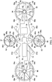
FIG. 1 is a perspective view of a personal air vehicle in hover mode in accordance with exemplary embodiments of the present disclosure; -
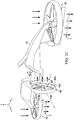
FIGS. 2A-2C are simplified representations of the personal air vehicle inFIG. 1 in various flight modes, in accordance with exemplary embodiments of the present disclosure; -
FIG. 3 is a schematic top view illustration of a power source for the personal air vehicle inFIG. 1 in accordance with exemplary embodiments of the present disclosure; -
FIG. 4 is a rear perspective view of the personal air vehicle inFIG. 1 in accordance with an exemplary embodiment of the present disclosure; -
FIG. 5A is a top view of a personal air vehicle in hover mode in accordance with exemplary embodiments of the present disclosure; and -
FIG. 5B is a top view of a personal air vehicle in a folded mode in accordance with exemplary embodiments of the present disclosure. - Illustrative embodiments of the apparatus and method are described below. In the interest of clarity, all features of an actual implementation may not be described in this specification. It will of course be appreciated that in the development of any such actual embodiment, numerous implementation-specific decisions must be made to achieve the developer's specific goals, such as compliance with system-related and business-related constraints, which will vary from one implementation to another. Moreover, it will be appreciated that such a development effort might be complex and time-consuming but would nevertheless be a routine undertaking for those of ordinary skill in the art having the benefit of this disclosure.
- In the specification, reference may be made to the spatial relationships between various components and to the spatial orientation of various aspects of components as the devices are depicted in the attached drawings. However, as will be recognized by those skilled in the art after a complete reading of the present application, the devices, members, apparatuses, etc. described herein may be positioned in any desired orientation. Thus, the use of terms such as "above," "below," "upper," "lower," or other like terms to describe a spatial relationship between various components or to describe the spatial orientation of aspects of such components should be understood to describe a relative relationship between the components or a spatial orientation of aspects of such components, respectively, as the device described herein may be oriented in any desired direction.
- A personal air vehicle using ducted fans is schematically illustrated and generally designated 10 in
FIGS. 1-4 . Personal air vehicle (PAV) 10 is designed to be a hoverbike that can be used to carry one, two, or more passengers, cargo, and/or data over a variety of terrains. PAV 10 is capable of operating in various flight modes similar to a helicopter including, but not limited to, a vertical landing and takeoff mode, a forward mode, a reverse mode, and a hover hold mode. The forward and reverse modes can be considered a forward flight mode and reverse flight mode, respectively. -
PAV 10 can fly in an out-of-ground effect (OGE) and/or an in-ground effect (IGE) sufficient to maneuver over and/or around obstacles. In further embodiments,PAV 10 can fly at altitudes from about 1 to about 9,500 feet above the ground. In some embodiments,PAV 10 can fly at altitudes from about 30 to about 50 feet above the ground. In particular embodiments,PAV 10 can fly at altitudes from about 6,000 to about 9,500 feet above the ground. - It should be appreciated that
PAV 10 is merely illustrative of a variety of manned wingless aircraft or hovercraft that can implement the embodiments disclosed herein. Wingless aircraft means an aircraft without laterally extending wing surfaces that provide lift during operation of the aircraft. Other aircraft or hovercraft implementations can include unmanned aerial vehicles (UAV) that can be used for the transport of people, cargo, and/or data for military, commercial, and residential purposes, to name a few examples. In manned embodiments, operator means the person riding and controllingPAV 10. In unmanned embodiments, operator means the person remotely controllingPAV 10. -
FIGS. 1 ,2A-2C , and4 depict three mutually orthogonal directions X, Y, and Z forming a three-dimensional frame of reference XYZ. Longitudinal axis X corresponds to the roll axis that extends through the center ofPAV 10 in the fore and after directions. Transverse axis Y is perpendicular to longitudinal axis X and corresponds to the pitch axis (also known as a control pitch axis or "CPA"). The X-Y plane is considered to be "horizontal." Vertical axis Z is the yaw axis and is oriented perpendicularly with respect to the X-Y plane. The X-Z plane and Y-Z plane are considered to be "vertical." - Referring to
FIGS. 1-4 ,PAV 10 includes abody 12 as the main support or fuselage.Body 12 can hold the operator and/or cargo as well as support front and rearducted fans ducted fans Fans PAV 10. The side tilting ductedfans body 12. - Each of the tilting
ducted fans FIGS. 1 and3-4 , and the vertical positions, shown inFIGS. 2A-2C . In the interest of clarity, only tilting ductedfan 60 will be discussed in detail. However, one of ordinary skill in the art will understand that the form and function of tilting ductedfan 62 will be fully known from the benefit of the disclosure herein related to the tiltingducted fan 60. Referring now toFIGS. 1 and3-4 ,PAV 10 is in a vertical takeoff and landing mode that can be considered to also be a hover mode with the side tiltingducted fan 60 in a generally horizontal position and generating a downward thrust T (thrust is in a downward direction to propel PAV upward).FIG. 2A showsPAV 10 in a forward flight mode such that tiltingducted fan 60 is in a non-horizontal position and generating a forward thrust T (e.g., thrust is in an aft direction to propelPAV 10 forward).FIG. 2B illustrates side tiltingducted fan 60 in a non-horizontal position (e.g., angled about the pivot axis P) between forward and hover modes, which can be used for roll and yaw control during operation ofPAV 10. In a reverse mode, shown inFIG. 2C , tiltingducted fan 60 is in a non-horizontal position. To achieve reverse mode, in one embodiment, tiltingducted fan 60 is pivoted about the pivot axis P to generate thrust T in a forward direction to propelPAV 10 rearward (opposite to that shown inFIG. 2A ). In another embodiment, shown inFIG. 2C , the rotation direction of the plurality ofblade assemblies 64 can be reversed (e.g., opposite from the rotation direction of the plurality of blades inFIG. 2A ) such that thrust T generated by tilting ductedfan 60 is in a forward direction to propelPAV 10 rearward. -
Body 12 includes aforward portion 14, acentral portion 16, and anaft portion 18. Theforward portion 14 includes aforward end 14a and theaft portion 18 includes anaft end 18a. Theforward end 14a and theaft end 18a are longitudinally spaced-apart ends defining a vehicle transverse axis Y.PAV 10 has aright side 20 and aleft side 22. -
Central portion 16 of thebody 12 supports at least one straddle-type seat 30; a pair ofhandle bar assemblies system display panel 36a; andwindshield 40.Seat 30 is designed to be ridden by an operator similar to a motorcycle.Seat 30 can be disposed in a recess in thebody 12 that includes arestraint system 30r.Restraint system 30r can be a four or five-point quick release harness for securing the operator to thebody 12 during operation. A pair offootwells 31 are laterally positioned on opposite sides of theseat 30 and include laterally spaced-apart inner 31a andouter edges 31b. In other embodiments, theseat 30 can be disposed generally or partially within an aerodynamic protective enclosure such thatseat 30 forms a cockpit in thebody 12. - It will be appreciated that the contemplated embodiment is configured showing one
seat 30 to provide anoperator area 30a. In other embodiments, thebody 12 can include asecondary area 30b for transporting at least one of the following: a passenger, cargo, a weapon, equipment, and combinations thereof. In an embodiment, thesecondary area 30b is adjacent to the operator (e.g., next to, in front of, behind, and/or below theoperator area 30a). In an exemplary embodiment, thesecondary area 30b is reachable by the operator. - A pair of
handle bar assemblies body 12 on each of the right and leftsides handle bar assemblies rear fans side fans handle switches vehicle 10. In an embodiment, turning of thehandle bar assemblies air directing slats ducted fans PAV 10. - Due to the many variables involved in the control of flight of
PAV 10, a computer-controlledflight control system 36 automates many of the functions required for safe, efficient operation.Flight control system 36 can actuation control components ofPAV 10 in response to control inputs generated by one or more of the following: (1) an on-board operator; (2) an operator located remote from the vehicle; (3) a partially autonomous system, such as an auto-pilot; and (4) a fully autonomous system, such as in an UAV operating in a fully autonomous manner.Flight control system 36 includes software-implemented flight control methods for generating responses to the inputs that are appropriate to a particular flight or mission regime. In an embodiment,flight control system 36 includes a fly-by-wire flight control system. In one embodiment,flight control system 36 includes a hover mode such that can include an automatic hover hold mode and/or position hold mode; for example, and not limitation,vehicle 10 maintains a hover position above the ground at a desired location (e.g., the operator can be in a "hands free" hover). In an embodiment, hover mode can be maintained without hand control by the operator or is otherwise "hands-free."Flight control system 36 facilitates operation ofPAV 10 by the operator. In one embodiment,flight control system 36permits PAV 10 to be flown by an operator with minimal pilot skills.Flight control system 36 can advantageously reduce or minimize pilot induced oscillations. -
Flight control system 36 can receive inputs from the operator, control components, and/or sensors. In one embodiment, theflight control system 36 can receive inputs from control components. In an embodiment, theflight control system 36 receives inputs fromswitches handle bar assemblies handle bar assemblies flight control system 36 receives inputs from a pair of pedal assemblies disposed in the footwells 31. In other embodiments, theflight control system 36 can receive voice and other inputs from the operator. It will be appreciated that in some embodiments, thebody 12 can include and theflight control system 36 can receive inputs from at least one of the following control components: a steering wheel, a brake pedal, a gas pedal, a gear shifter, a stick, a lever, an engine throttle, and yaw pedals. A plurality ofsensors 37 can be disposed on theforward portion 14,central portion 16, and/oraft portion 18 of thebody 12 to detect various physical parameters (e.g., gyro sensors, acceleration sensors). -
Flight control system 36 can be displayed onpanel 36a and/or projected onto or into thewindshield 40 so as to be within the operator's field of vision when operatingvehicle 10.Panel 36a can be arranged in front of, adjacent to, and/or above the operator in order to be substantially accessible during operation.Panel 36a can be a touch-screen instrument panel that replaces the plurality of instruments, dials, gauges, and screens typically utilized on the console of an aircraft or automobile. Flightcontrol system panel 36a can include instruments and mission related displays of information such as, but not limited to, speed, distance traveled, fuel gauge, vehicle position, vehicle orientation, weapons systems, radar controls, electronic jamming, and combinations thereof. In an embodiment,flight control system 36 can be displayed on apanel 36a remote from PAV 10 (e.g., on operator's watch, gear, helmet and/or at a flight control center). -
Windshield 40 has an aerodynamic shape and is supported by thebody 12. In some embodiments,windshield 40 can be constructed of a bullet resistant transparent material. -
PAV 10 can, for example, be coupled to and controlled by adrive system 70 connected to apower source 72. Aremovable panel 17 in thebody 12 can provide access to thedrive system 70 and other operational systems.Drive system 70 can be an electric, hydraulic, and/or a conventional mechanical drive system. - In one embodiment, shown in
FIG. 3 ,power source 72 includes abattery 74, agenerator 76, and acombustion engine 78.Power source 72 provides electrical power toelectric motors ducted fans ducted fans Electric motors respective hub ducted fans Electric motors respective hub fans Air intake ducts 78i can be configured to direct airflow tocombustion engine 78 during operation.Exhaust ports 78v can be disposed in theaft portion 18 and can be configured to selectively feed hot air away from thecombustion engine 78 during operation. - Each of the front and rear
ducted fans body 12 and can generate a variable thrust. Front ductedfan 50 is disposed on theforward portion 14 and can include aflange 14f that can act as a guard to prevent the operator (e.g., a hand and/or foot) from coming into direct contact withducted fan 50 during operation. In an embodiment, frontducted fan 50 is rigidly attached to theforward end 14a of thebody 12 at thehub 50a. Rear ductedfan 52 is disposed on theaft portion 18 athub 52a. In an embodiment, rearducted fan 52 is rigidly attached to theaft end 18a ofbody 12. Asuspension member aft portions body 12 to provide support for themotors suspension members - Each of the
ducted fans duct rotor hub assemblies blade assemblies blade assemblies PAV 10. Indeed, in an embodiment, the rotational speed of the plurality ofblade assemblies ducted fan blade assemblies 54a ofducted fan 50 may be higher or lower than the rotor speed ofblade assemblies 56a ofducted fan 52 such that the thrusts generated by eachducted fan ducted fans PAV 10. An embodiment provides that forward and rearducted fans - In an embodiment, each front and rear
ducted fan air directing slats ducted fan air directing slat slat actuator respective duct particular slat air directing slats ducted fans vehicle 10. - Each of the side tilting
ducted fans body 12 and can generate a variable thrust. Side tiltingducted fans side body 12 in thecentral portion 16 of thebody 12. In an embodiment, right and leftsides support member fan support member flange ducted fan ducted fans duct rotor hub assemblies blade assemblies - Side tilting
ducted fans actuators actuators power source 72. In an exemplary embodiment, eachactuator body support members body 12. - Rotational speed of the plurality of
blade assemblies PAV 10. In an embodiment, the rotational speed of the plurality ofblade assemblies ducted fan blade assemblies 64a ofducted fan 60 may be higher or lower than the rotor speed ofblade assemblies 66a ofducted fan 62 such that the thrusts generated by eachducted fan ducted fan 60 and left tiltingducted fan 62 rotate in opposite directions from one another for torque balancing ofPAV 10. - As shown in
FIG. 3 , each of theducted fans vertical support horizontal support rotor hub assemblies - Each of the
ducts ducted fans ducts Ducts ducted fans -
Landing gear assemblies vehicle 10.Landing gear assemblies body 12 for contacting with the ground. Eachlanding gear assembly retractable arms base base arms arms bottom surface 19 ofbody 12. In an embodiment, thelanding gear assemblies landing gear assemblies - There are numerous secondary areas on
vehicle 10 that can be used for example, but not limitation, passengers, cargo, weapons, equipment, and/or combinations thereof. Referring toFIG. 1 , there is asecondary area 30b adjacent to theoperator area 30a. It should be appreciated that thesecondary area 30b may be located in a wide variety of locations on or in thebody 12, e.g., the top, bottom, front, back, and sides of thebody 12. In an embodiment, shown inFIG. 4 , there is asecondary area 30b' disposed on the bottom 19 of thebody 12 for mounting aweapon 98 thereon.Weapon 98 can be operably controlled by at least theflight control system 36. In other embodiments,body 12 can have an extended length such that thesecondary area 30b' has a sufficient length and width for at least one of the following: passengers, cargo, weapons, equipment, and/or combinations thereof. In some embodiments, the secondary area can be located on and/or in theforward portion 14,central portion 16, andaft portion 18 of thevehicle 10. -
FIGS. 5A-5B shows apersonal air vehicle 110. Certain features ofpersonal air vehicle 110 are as described above and bear similar reference characters topersonal air vehicle 10, but with a leading '1'.Personal air vehicle 110 includessecondary area 130b" adjacent tooperator area 130a and on top of theforward portion 14. In the illustrative embodiment ofFIG. 5A , thesecondary area 130b" is used for storage ofweapons sides secondary area 130b" is reachable by the operator. In an embodiment, the operator can lock thevehicle 110 in a hover mode usingflight control system 136 and reach forweapons PAV 110. - In an embodiment, the
flight control system 136 can include an automatic center of gravity (CG) adjustment in hover mode during firing of aweapon 198 by the operator or whenPAV 110 encounters other CG modifiers; for example, and not limitation, wind, cargo, passengers, ballistic strike. In some embodiments,flight control system 136 can include hands-free landing and takeoff mode that can be particularly useful for ingress and egress in combat missions. - In an embodiment,
flight control system 136 can provide situational information related to the flight, mission, and/or job to the operator when the operator is remote fromPAV 10. An embodiment provides thatPAV 10 can function as a lookout for theoperator 30 when the operator is remote from PAV 10 (e.g.,PAV 10 is located at a position above the operator to assess the terrain, operator's current location, and incoming targets that the operator cannot see while on the ground). Whenflight control system 136 identifies situational information, the information can be relayed to the operator and/or control personnel at a base or flight command center. In an embodiment,flight control system 136 can positionPAV 110 to provide protection from a ballistic strike for the operator when the operator is remote from PAV 110 (e.g., using bullet resistant materials on thebody 12 ofPAV 10 and/orPAV 10 can be positioned by theflight control system 136 between the incoming ballistic material and the operator). In yet another embodiment,flight control system 136 can positionPAV 110 to achieve ballistic requests made by the operator when remote fromPAV 110 and/or control personnel at a base or flight command center. - In an embodiment, tilting
ducted fans FIG. 5B . In an embodiment, each of tiltingducted fans fold axis ducted fans fold axis PAV 110. Foldaxes respective support member axes support member flange ducted fans ducted fans fans - While the illustrative embodiments are described as providing thrust for a personal air vehicle, the illustrative embodiments may also be scaled up for larger aircraft. In these alternative embodiments, there may be more or larger ducted fans in a variety of configurations to support the heavier aircraft.
- The illustrative embodiments of the personal air vehicle with ducted fans described herein advantageously provide a hoverbike that can be used for military, police, and border patrol applications. Moreover, the illustrative embodiments of the personal air vehicle with ducted fans can provide at least one of the following advantages: easy to operate hoverbike; capable of transporting passengers, cargo, and/or data; and can be used for military, police, commercial, and residential applications.
- At least one embodiment is disclosed and variations, combinations, and/or modifications of the embodiment(s) and/or features of the embodiment(s) made by a person having ordinary skill in the art is within the scope of the disclosure. Alternative embodiments that result from combining, integrating, and/or omitting features of the embodiment(s) are also within the scope of the disclosure. Where numerical ranges or limitations are expressly stated, such express ranges or limitations should be understood to include iterative ranges or limitations of like magnitude falling within the expressly stated ranges or limitations (e.g., from about 1 to about 10 includes 2, 3, 4, etc.; greater than 0.10 includes 0.11, 0.12, 0.13, etc.). For example, whenever a numerical range with a lower limit, Rl, and an upper, Ru, is disclosed, any number falling within the range is specifically disclosed. In particular, the following numbers within the range are specifically disclosed: R=R1+k*(Ru-R1), wherein k is a variable ranging from 1 percent to 100 percent with a 1 percent increment, i.e., k is 1 percent, 2 percent, 3 percent, 4 percent, 5 percent, ..., 50 percent, 51 percent, 52 percent, ...., 95 percent, 96 percent, 97 percent, 98 percent, 99 percent, or 100 percent. Unless otherwise stated, the term "about" shall mean plus or minus 5 percent of the subsequent value. Moreover, any numerical range defined by two R numbers as defined in the above is also specifically disclosed. Use of the term "optionally" with respect to any element of a claim means that the element is required, or alternatively, the element is not required, both alternatives being within the scope of the claim. Use of broader terms such as comprises, includes, and having should be understood to provide support for narrow terms such as consisting of, consisting essentially of, and comprised substantially of. Accordingly, the scope of protection is not limited by the description set out above but is defined by the claims that follow, the scope including all equivalents of the subject matter of the claims. Each and every claim is incorporated as further disclosure into the specification and the claims are embodiment(s) of the present invention.
Claims (18)
- A personal air vehicle comprising:a body having a forward portion, a central portion and an aft portion;a first ducted fan supported by the forward portion of the body;a second ducted fan supported by the aft portion of the body; andthird and fourth ducted fans supported by the left and right sides of the body and pivotable relative to the body.
- The vehicle according to claim 1, wherein the third and fourth ducted fans are pivotable relative to the body in a horizontal orientation for a hover mode.
- The vehicle according to claim 1 or claim 2, wherein the third and fourth ducted fans are pivotable relative to the body in a non-horizontal orientation.
- The vehicle according to claim 3, wherein the non-horizontal orientation is in a forward mode, or wherein the non-horizontal orientation is in a reverse mode.
- The vehicle according to claim 1 or any preceding claim, wherein the third and fourth ducted fans are disposed on the central portion of the body, and/or wherein at least one of the third ducted fan and the fourth ducted fan is adjacent to a bottom surface of the body.
- The vehicle according to claim 1 or any preceding claim, wherein the third ducted fan and the fourth ducted fan are foldable.
- The vehicle according to claim 1 or any preceding claim, wherein the vehicle is configured to generate roll control by selectively differentiating a collective power in the third and fourth ducted fans, in any combination so as to produce a desired differential in thrust angle between the right side and the left side of the vehicle.
- The vehicle according to claim 1 or any preceding claim, wherein at least one of the first ducted fan, the second ducted fan, the third ducted fan, and the fourth ducted fan generates a variable thrust.
- The vehicle according to claim 1 or any preceding claim, wherein the first ducted fan and the second ducted fan are each rotatable about an axis substantially perpendicular to the vehicle longitudinal axis, and/or wherein the axes of rotation of the third ducted fan and the fourth ducted fan are each pivotable about a pivot axis.
- The vehicle according to claim 1 or any preceding claim, wherein the vehicle is wingless.
- The vehicle according to claim 1 or any preceding claim, wherein the vehicle is configured to generate pitch and yaw control by selectively differentiating a collective power in the first ducted fan and the second ducted fan, in any combination so as to produce a desired differential in thrust angle between the forward and aft portions of the vehicle, and/or wherein at least one of the first ducted fan and the second ducted fan further comprising a pair of air directing slats for providing yaw control of the vehicle.
- The vehicle according to claim 1 or any preceding claim, further comprising:a flight control system operable to change at least one operating condition of at least one of the first, second, third, and fourth ducted fans; andan operator control device in communication with the flight control system and operable to receive a command from an operator, and optionally or preferably:-(i) wherein the operator control device is a pair of handle bar assemblies, and/or(ii) wherein the flight control system further comprising a hover hold mode.
- The vehicle according to claim 1 or any preceding claim, wherein the body further comprising an operator area and a secondary area.
- The vehicle according to claim 13, wherein:-(i) the secondary area supports at least one of the following: a passenger, cargo, a weapon, equipment, and combinations thereof; or(ii) wherein the secondary area is adjacent to the operator area; or(iii) wherein the secondary area is reachable by the operator; or(iv) wherein the operator area comprises a straddle seat for the operator; or(v) any combination of features (i), (ii), (iii) and (iv) is provided in any number.
- The vehicle according to claim 1 or any preceding claim, wherein the body further comprises a retractable landing gear assembly, and optionally or preferably wherein the landing gear assembly comprising a base and a pair of retractable arms extending from the base for contacting the ground.
- A method of flying a personal air vehicle, the method comprising:providing the vehicle of claim 1; andproducing using at least the first ducted fan and the second ducted fan a vertical thrust to cause the vehicle to ascend.
- The method of claim 16, further comprising:(i) pivoting a pair of air directing slats on at least one of the first ducted fan and the second ducted fan to provide yaw control of the vehicle, and/or(ii) producing using the third ducted fan and the fourth ducted fan a vertical thrust to cause the vehicle to ascend.
- The method according to claim 16 or claim 17, further comprising:(i) producing using the third ducted fan and the fourth ducted fan a forward thrust to cause the vehicle to move forward, or(ii) producing using the third ducted fan and the fourth ducted fan a reverse thrust to cause the vehicle to move rearward, or(iii) pivoting at least one of the third and fourth ducted fans to control at least one of the roll and yaw of the vehicle.
Applications Claiming Priority (1)
| Application Number | Priority Date | Filing Date | Title |
|---|---|---|---|
| US15/623,328 US10730622B2 (en) | 2017-06-14 | 2017-06-14 | Personal air vehicle with ducted fans |
Publications (2)
| Publication Number | Publication Date |
|---|---|
| EP3415423A1 true EP3415423A1 (en) | 2018-12-19 |
| EP3415423B1 EP3415423B1 (en) | 2019-11-06 |
Family
ID=59581760
Family Applications (1)
| Application Number | Title | Priority Date | Filing Date |
|---|---|---|---|
| EP17185565.3A Active EP3415423B1 (en) | 2017-06-14 | 2017-08-09 | Personal air vehicle with ducted fans |
Country Status (2)
| Country | Link |
|---|---|
| US (1) | US10730622B2 (en) |
| EP (1) | EP3415423B1 (en) |
Cited By (6)
| Publication number | Priority date | Publication date | Assignee | Title |
|---|---|---|---|---|
| US10730622B2 (en) | 2017-06-14 | 2020-08-04 | Bell Helicopter Textron Inc. | Personal air vehicle with ducted fans |
| WO2021046592A1 (en) * | 2019-09-11 | 2021-03-18 | Skyborne Technologies Pty Ltd | An armed unmanned aerial vehicle and methods of use thereof |
| KR20220100237A (en) * | 2021-01-08 | 2022-07-15 | 주식회사 스페이스로보틱스 | Portable aircraft for manned boarding |
| EP4043343A4 (en) * | 2019-10-08 | 2023-06-21 | A.L.I. Technologies Inc. | FLYING VEHICLE |
| CN117104546A (en) * | 2023-10-16 | 2023-11-24 | 中国空气动力研究与发展中心计算空气动力研究所 | Multi-duct unmanned aerial vehicle and control method |
| US12221210B2 (en) | 2021-10-25 | 2025-02-11 | Levanta Tech Inc. | Wing-in-ground effect vehicles and uses thereof |
Families Citing this family (23)
| Publication number | Priority date | Publication date | Assignee | Title |
|---|---|---|---|---|
| US10641616B2 (en) * | 2016-02-02 | 2020-05-05 | GeoThinkTank LLC | Remote sensing calibration, validation, and signature characterization from unmanned aircraft systems |
| WO2018134795A1 (en) * | 2017-01-23 | 2018-07-26 | Urban Aeronautics, Ltd. | Method of drag reduction on vehicle with internal rotors |
| US11673676B2 (en) * | 2017-02-23 | 2023-06-13 | William J. Neff | Hybrid VTOL aerial vehicle |
| ES2933378T3 (en) * | 2018-04-27 | 2023-02-06 | Textron Systems Corp | Variable pitch rotor assembly for electrically actuated thrust vectored aircraft applications |
| WO2020191489A1 (en) * | 2019-03-28 | 2020-10-01 | 10270725 Canada Corp. | Multicopter helicopter and method of manufacture thereof |
| JP2020158100A (en) * | 2019-06-25 | 2020-10-01 | 株式会社A.L.I.Technologies | Flying vehicle |
| WO2021076250A2 (en) * | 2019-09-11 | 2021-04-22 | Alexandru Balan | 360° advanced rotation system |
| USD919548S1 (en) * | 2020-01-03 | 2021-05-18 | Bell Textron Inc. | Ducted rotor |
| US11554915B2 (en) | 2020-03-02 | 2023-01-17 | Goodrich Corporation | Cargo aisle drive system |
| US11472544B2 (en) | 2020-03-04 | 2022-10-18 | Textron Innovations Inc. | Electric drive system line replaceable unit with integrated collective actuation |
| US11554859B2 (en) | 2020-03-04 | 2023-01-17 | Textron Innovations Inc. | Electric drive system line replaceable unit with integrated thermal cooling |
| US11565803B2 (en) | 2020-03-04 | 2023-01-31 | Textron Innovations Inc. | Electric drive system line replaceable unit with integrated cyclic actuation |
| US11591081B2 (en) | 2020-06-08 | 2023-02-28 | Textron Innovations Inc. | Vertical-lift augmentation system |
| US11407504B2 (en) | 2020-06-19 | 2022-08-09 | Textron Innovations Inc. | Tip gap control systems with inner duct control surfaces |
| US11479350B2 (en) | 2020-06-19 | 2022-10-25 | Textron Innovations Inc. | Tip gap monitoring systems for ducted aircraft |
| US11370536B2 (en) | 2020-06-19 | 2022-06-28 | Textron Innovations Inc. | Tip gap control systems with active blade tips |
| US11203421B1 (en) | 2020-06-19 | 2021-12-21 | Textron Innovations Inc. | Passive tip gap management systems for ducted aircraft |
| US11273910B2 (en) | 2020-06-19 | 2022-03-15 | Textron Innovations Inc. | Sacrificial blade tips for ducted aircraft |
| US11831220B2 (en) | 2020-06-22 | 2023-11-28 | Textron Innovations Inc. | Electric motor stack with integral one-piece gearbox input shaft |
| US11390395B2 (en) | 2020-06-25 | 2022-07-19 | Textron Innovations Inc. | Aircraft rotor assembly with segmented input shaft for electric motor stack and gearbox unit |
| US11492107B2 (en) | 2020-07-22 | 2022-11-08 | Textron Innovations Inc. | Ducted proprotor systems having adaptive duct geometries |
| US11827344B2 (en) * | 2020-12-09 | 2023-11-28 | Textron Innovations Inc. | Low noise ducted fan |
| US11814163B2 (en) | 2021-01-13 | 2023-11-14 | Textron Innovations Inc. | Electric tiltrotor aircraft with tilting coaxial motors and gearbox |
Citations (4)
| Publication number | Priority date | Publication date | Assignee | Title |
|---|---|---|---|---|
| WO2005072233A2 (en) * | 2004-01-22 | 2005-08-11 | Ufoz, Llc | Quiet vertical takeoff and landing aircraft using ducted, magnetic induction air-impeller rotors |
| US20060226281A1 (en) * | 2004-11-17 | 2006-10-12 | Walton Joh-Paul C | Ducted fan vertical take-off and landing vehicle |
| US20140158816A1 (en) * | 2012-12-07 | 2014-06-12 | Delorean Aerospace, Llc | Vertical Takeoff and Landing Aircraft |
| DE102014115926A1 (en) * | 2014-10-31 | 2016-05-04 | Johann Schwöller | Drive module for a motor vehicle and motor vehicle with such a drive module |
Family Cites Families (16)
| Publication number | Priority date | Publication date | Assignee | Title |
|---|---|---|---|---|
| US4498645A (en) | 1982-10-28 | 1985-02-12 | Hardy Arthur L | Wingless aircraft with ducted variable pitch airfoils |
| US5115996A (en) | 1990-01-31 | 1992-05-26 | Moller International, Inc. | Vtol aircraft |
| US8720814B2 (en) | 2005-10-18 | 2014-05-13 | Frick A. Smith | Aircraft with freewheeling engine |
| US7874513B1 (en) | 2005-10-18 | 2011-01-25 | Smith Frick A | Apparatus and method for vertical take-off and landing aircraft |
| US20080054121A1 (en) * | 2006-05-11 | 2008-03-06 | Urban Aeronautics Ltd. | Ducted fan VTOL vehicles |
| US8056866B2 (en) * | 2006-09-28 | 2011-11-15 | Aerofex, Inc. | Air-vehicle augmented kinesthetic control system |
| US8833692B2 (en) * | 2006-11-27 | 2014-09-16 | Urban Aeronautics Ltd. | Wall effects on VTOL vehicles |
| WO2008135973A2 (en) * | 2007-05-02 | 2008-11-13 | Urban Aeronautics Ltd. | Control flows and forces in vtol vehicles |
| EP2595882B1 (en) | 2010-07-19 | 2016-06-08 | Zee.Aero Inc. | Personal aircraft |
| US8579227B2 (en) | 2011-01-24 | 2013-11-12 | J. Kellogg Burnham | Vertical and horizontal flight aircraft “sky rover” |
| WO2013105926A1 (en) | 2011-03-22 | 2013-07-18 | Aerovironment Inc. | Invertible aircraft |
| TWI538852B (en) | 2011-07-19 | 2016-06-21 | 季航空股份有限公司 | Personal aircraft |
| EP2724934B1 (en) | 2012-10-26 | 2016-09-21 | AGUSTAWESTLAND S.p.A. | Hover-capable aircraft |
| WO2017173159A1 (en) * | 2016-03-31 | 2017-10-05 | Russell David Wayne | System and method for safe deliveries by unmanned aerial vehicles |
| US20180127094A1 (en) * | 2016-11-07 | 2018-05-10 | ZipAir SAS | Systems and methods for improved flight control |
| US10730622B2 (en) | 2017-06-14 | 2020-08-04 | Bell Helicopter Textron Inc. | Personal air vehicle with ducted fans |
-
2017
- 2017-06-14 US US15/623,328 patent/US10730622B2/en not_active Expired - Fee Related
- 2017-08-09 EP EP17185565.3A patent/EP3415423B1/en active Active
Patent Citations (4)
| Publication number | Priority date | Publication date | Assignee | Title |
|---|---|---|---|---|
| WO2005072233A2 (en) * | 2004-01-22 | 2005-08-11 | Ufoz, Llc | Quiet vertical takeoff and landing aircraft using ducted, magnetic induction air-impeller rotors |
| US20060226281A1 (en) * | 2004-11-17 | 2006-10-12 | Walton Joh-Paul C | Ducted fan vertical take-off and landing vehicle |
| US20140158816A1 (en) * | 2012-12-07 | 2014-06-12 | Delorean Aerospace, Llc | Vertical Takeoff and Landing Aircraft |
| DE102014115926A1 (en) * | 2014-10-31 | 2016-05-04 | Johann Schwöller | Drive module for a motor vehicle and motor vehicle with such a drive module |
Cited By (10)
| Publication number | Priority date | Publication date | Assignee | Title |
|---|---|---|---|---|
| US10730622B2 (en) | 2017-06-14 | 2020-08-04 | Bell Helicopter Textron Inc. | Personal air vehicle with ducted fans |
| WO2021046592A1 (en) * | 2019-09-11 | 2021-03-18 | Skyborne Technologies Pty Ltd | An armed unmanned aerial vehicle and methods of use thereof |
| US12129011B2 (en) | 2019-09-11 | 2024-10-29 | Skyborne Technologies Pty. Ltd. | Armed unmanned aerial vehicle and methods of use thereof |
| AU2020345856B2 (en) * | 2019-09-11 | 2025-08-07 | Skyborne Technologies Pty Ltd | An armed unmanned aerial vehicle and methods of use thereof |
| EP4043343A4 (en) * | 2019-10-08 | 2023-06-21 | A.L.I. Technologies Inc. | FLYING VEHICLE |
| KR20220100237A (en) * | 2021-01-08 | 2022-07-15 | 주식회사 스페이스로보틱스 | Portable aircraft for manned boarding |
| US12221210B2 (en) | 2021-10-25 | 2025-02-11 | Levanta Tech Inc. | Wing-in-ground effect vehicles and uses thereof |
| US12606302B2 (en) | 2021-10-25 | 2026-04-21 | Levanta Tech Inc. | Wing-in-ground effect vehicles and uses thereof |
| CN117104546A (en) * | 2023-10-16 | 2023-11-24 | 中国空气动力研究与发展中心计算空气动力研究所 | Multi-duct unmanned aerial vehicle and control method |
| CN117104546B (en) * | 2023-10-16 | 2024-01-05 | 中国空气动力研究与发展中心计算空气动力研究所 | Multi-duct unmanned aerial vehicle and control method |
Also Published As
| Publication number | Publication date |
|---|---|
| US20180362160A1 (en) | 2018-12-20 |
| EP3415423B1 (en) | 2019-11-06 |
| US10730622B2 (en) | 2020-08-04 |
Similar Documents
| Publication | Publication Date | Title |
|---|---|---|
| EP3415423B1 (en) | Personal air vehicle with ducted fans | |
| US11713115B2 (en) | Aeronautical car and associated features | |
| US12312073B2 (en) | System of play platform for multi-mission application spanning any one or combination of domains or environments | |
| KR102252165B1 (en) | Unmanned aerial vehicle | |
| US10676180B2 (en) | Multi-rotor personal air vehicle with a central lifting fan | |
| US11661183B2 (en) | Small light vertical take-off and landing capable delta wing aircraft | |
| EP3140190B1 (en) | Vtol aircraft | |
| US8220737B2 (en) | VTOL aerial vehicle | |
| US8936212B1 (en) | System and method for compact and combinable aerial vehicle capable of vertical/short takeoff and landing | |
| EP2928772B1 (en) | Vertical takeoff and landing aircraft | |
| US20170247107A1 (en) | Rotary-wing vehicle and system | |
| US20170072755A1 (en) | Amphibious vertical takeoff and landing (vtol) unmanned device with ai (artificial intelligence) data processing mobile and wearable applications apparatus, same as jet drone, jet flying car, private vtol jet, personal jet aircraft with gsp vtol jet engines and self-jet charged and solar cells powered hybrid super jet electrical car all in one (electricity/fuel) | |
| US20160207368A1 (en) | Vertical Take-Off and Landing Roadable Aircraft | |
| US20160244159A1 (en) | Controlled Take-Off And Flight System Using Thrust Differentials | |
| CN111566008A (en) | Variable geometry vertical take-off and landing (VTOL) aircraft system | |
| US20060113426A1 (en) | Vtol vehicles | |
| EP3959126B1 (en) | Vertical take-off and landing aircraft and related control method | |
| WO2018087614A1 (en) | Amphibious vertical takeoff and landing unmanned device | |
| US20060284002A1 (en) | Unmanned Urban Aerial Vehicle | |
| CA2840823A1 (en) | Vertical take-off and landing roadable aircraft | |
| WO2017165039A2 (en) | Rotary-wing vehicle and system | |
| NL1040979B1 (en) | Air vehicle. |
Legal Events
| Date | Code | Title | Description |
|---|---|---|---|
| STAA | Information on the status of an ep patent application or granted ep patent |
Free format text: STATUS: EXAMINATION IS IN PROGRESS |
|
| PUAI | Public reference made under article 153(3) epc to a published international application that has entered the european phase |
Free format text: ORIGINAL CODE: 0009012 |
|
| 17P | Request for examination filed |
Effective date: 20170809 |
|
| AK | Designated contracting states |
Kind code of ref document: A1 Designated state(s): AL AT BE BG CH CY CZ DE DK EE ES FI FR GB GR HR HU IE IS IT LI LT LU LV MC MK MT NL NO PL PT RO RS SE SI SK SM TR |
|
| AX | Request for extension of the european patent |
Extension state: BA ME |
|
| GRAP | Despatch of communication of intention to grant a patent |
Free format text: ORIGINAL CODE: EPIDOSNIGR1 |
|
| STAA | Information on the status of an ep patent application or granted ep patent |
Free format text: STATUS: GRANT OF PATENT IS INTENDED |
|
| INTG | Intention to grant announced |
Effective date: 20190409 |
|
| GRAS | Grant fee paid |
Free format text: ORIGINAL CODE: EPIDOSNIGR3 |
|
| GRAA | (expected) grant |
Free format text: ORIGINAL CODE: 0009210 |
|
| STAA | Information on the status of an ep patent application or granted ep patent |
Free format text: STATUS: THE PATENT HAS BEEN GRANTED |
|
| AK | Designated contracting states |
Kind code of ref document: B1 Designated state(s): AL AT BE BG CH CY CZ DE DK EE ES FI FR GB GR HR HU IE IS IT LI LT LU LV MC MK MT NL NO PL PT RO RS SE SI SK SM TR |
|
| REG | Reference to a national code |
Ref country code: GB Ref legal event code: FG4D |
|
| REG | Reference to a national code |
Ref country code: CH Ref legal event code: EP Ref country code: AT Ref legal event code: REF Ref document number: 1198429 Country of ref document: AT Kind code of ref document: T Effective date: 20191115 |
|
| REG | Reference to a national code |
Ref country code: DE Ref legal event code: R096 Ref document number: 602017008376 Country of ref document: DE |
|
| REG | Reference to a national code |
Ref country code: IE Ref legal event code: FG4D |
|
| REG | Reference to a national code |
Ref country code: NL Ref legal event code: MP Effective date: 20191106 |
|
| REG | Reference to a national code |
Ref country code: LT Ref legal event code: MG4D |
|
| PG25 | Lapsed in a contracting state [announced via postgrant information from national office to epo] |
Ref country code: LT Free format text: LAPSE BECAUSE OF FAILURE TO SUBMIT A TRANSLATION OF THE DESCRIPTION OR TO PAY THE FEE WITHIN THE PRESCRIBED TIME-LIMIT Effective date: 20191106 Ref country code: SE Free format text: LAPSE BECAUSE OF FAILURE TO SUBMIT A TRANSLATION OF THE DESCRIPTION OR TO PAY THE FEE WITHIN THE PRESCRIBED TIME-LIMIT Effective date: 20191106 Ref country code: FI Free format text: LAPSE BECAUSE OF FAILURE TO SUBMIT A TRANSLATION OF THE DESCRIPTION OR TO PAY THE FEE WITHIN THE PRESCRIBED TIME-LIMIT Effective date: 20191106 Ref country code: BG Free format text: LAPSE BECAUSE OF FAILURE TO SUBMIT A TRANSLATION OF THE DESCRIPTION OR TO PAY THE FEE WITHIN THE PRESCRIBED TIME-LIMIT Effective date: 20200206 Ref country code: NL Free format text: LAPSE BECAUSE OF FAILURE TO SUBMIT A TRANSLATION OF THE DESCRIPTION OR TO PAY THE FEE WITHIN THE PRESCRIBED TIME-LIMIT Effective date: 20191106 Ref country code: LV Free format text: LAPSE BECAUSE OF FAILURE TO SUBMIT A TRANSLATION OF THE DESCRIPTION OR TO PAY THE FEE WITHIN THE PRESCRIBED TIME-LIMIT Effective date: 20191106 Ref country code: PT Free format text: LAPSE BECAUSE OF FAILURE TO SUBMIT A TRANSLATION OF THE DESCRIPTION OR TO PAY THE FEE WITHIN THE PRESCRIBED TIME-LIMIT Effective date: 20200306 Ref country code: NO Free format text: LAPSE BECAUSE OF FAILURE TO SUBMIT A TRANSLATION OF THE DESCRIPTION OR TO PAY THE FEE WITHIN THE PRESCRIBED TIME-LIMIT Effective date: 20200206 Ref country code: GR Free format text: LAPSE BECAUSE OF FAILURE TO SUBMIT A TRANSLATION OF THE DESCRIPTION OR TO PAY THE FEE WITHIN THE PRESCRIBED TIME-LIMIT Effective date: 20200207 Ref country code: PL Free format text: LAPSE BECAUSE OF FAILURE TO SUBMIT A TRANSLATION OF THE DESCRIPTION OR TO PAY THE FEE WITHIN THE PRESCRIBED TIME-LIMIT Effective date: 20191106 |
|
| PG25 | Lapsed in a contracting state [announced via postgrant information from national office to epo] |
Ref country code: RS Free format text: LAPSE BECAUSE OF FAILURE TO SUBMIT A TRANSLATION OF THE DESCRIPTION OR TO PAY THE FEE WITHIN THE PRESCRIBED TIME-LIMIT Effective date: 20191106 Ref country code: HR Free format text: LAPSE BECAUSE OF FAILURE TO SUBMIT A TRANSLATION OF THE DESCRIPTION OR TO PAY THE FEE WITHIN THE PRESCRIBED TIME-LIMIT Effective date: 20191106 Ref country code: IS Free format text: LAPSE BECAUSE OF FAILURE TO SUBMIT A TRANSLATION OF THE DESCRIPTION OR TO PAY THE FEE WITHIN THE PRESCRIBED TIME-LIMIT Effective date: 20200306 |
|
| PG25 | Lapsed in a contracting state [announced via postgrant information from national office to epo] |
Ref country code: AL Free format text: LAPSE BECAUSE OF FAILURE TO SUBMIT A TRANSLATION OF THE DESCRIPTION OR TO PAY THE FEE WITHIN THE PRESCRIBED TIME-LIMIT Effective date: 20191106 |
|
| PG25 | Lapsed in a contracting state [announced via postgrant information from national office to epo] |
Ref country code: RO Free format text: LAPSE BECAUSE OF FAILURE TO SUBMIT A TRANSLATION OF THE DESCRIPTION OR TO PAY THE FEE WITHIN THE PRESCRIBED TIME-LIMIT Effective date: 20191106 Ref country code: CZ Free format text: LAPSE BECAUSE OF FAILURE TO SUBMIT A TRANSLATION OF THE DESCRIPTION OR TO PAY THE FEE WITHIN THE PRESCRIBED TIME-LIMIT Effective date: 20191106 Ref country code: ES Free format text: LAPSE BECAUSE OF FAILURE TO SUBMIT A TRANSLATION OF THE DESCRIPTION OR TO PAY THE FEE WITHIN THE PRESCRIBED TIME-LIMIT Effective date: 20191106 Ref country code: EE Free format text: LAPSE BECAUSE OF FAILURE TO SUBMIT A TRANSLATION OF THE DESCRIPTION OR TO PAY THE FEE WITHIN THE PRESCRIBED TIME-LIMIT Effective date: 20191106 Ref country code: DK Free format text: LAPSE BECAUSE OF FAILURE TO SUBMIT A TRANSLATION OF THE DESCRIPTION OR TO PAY THE FEE WITHIN THE PRESCRIBED TIME-LIMIT Effective date: 20191106 |
|
| REG | Reference to a national code |
Ref country code: DE Ref legal event code: R097 Ref document number: 602017008376 Country of ref document: DE |
|
| REG | Reference to a national code |
Ref country code: AT Ref legal event code: MK05 Ref document number: 1198429 Country of ref document: AT Kind code of ref document: T Effective date: 20191106 |
|
| PG25 | Lapsed in a contracting state [announced via postgrant information from national office to epo] |
Ref country code: SM Free format text: LAPSE BECAUSE OF FAILURE TO SUBMIT A TRANSLATION OF THE DESCRIPTION OR TO PAY THE FEE WITHIN THE PRESCRIBED TIME-LIMIT Effective date: 20191106 Ref country code: SK Free format text: LAPSE BECAUSE OF FAILURE TO SUBMIT A TRANSLATION OF THE DESCRIPTION OR TO PAY THE FEE WITHIN THE PRESCRIBED TIME-LIMIT Effective date: 20191106 |
|
| PLBE | No opposition filed within time limit |
Free format text: ORIGINAL CODE: 0009261 |
|
| STAA | Information on the status of an ep patent application or granted ep patent |
Free format text: STATUS: NO OPPOSITION FILED WITHIN TIME LIMIT |
|
| 26N | No opposition filed |
Effective date: 20200807 |
|
| PG25 | Lapsed in a contracting state [announced via postgrant information from national office to epo] |
Ref country code: AT Free format text: LAPSE BECAUSE OF FAILURE TO SUBMIT A TRANSLATION OF THE DESCRIPTION OR TO PAY THE FEE WITHIN THE PRESCRIBED TIME-LIMIT Effective date: 20191106 Ref country code: SI Free format text: LAPSE BECAUSE OF FAILURE TO SUBMIT A TRANSLATION OF THE DESCRIPTION OR TO PAY THE FEE WITHIN THE PRESCRIBED TIME-LIMIT Effective date: 20191106 |
|
| PG25 | Lapsed in a contracting state [announced via postgrant information from national office to epo] |
Ref country code: MC Free format text: LAPSE BECAUSE OF FAILURE TO SUBMIT A TRANSLATION OF THE DESCRIPTION OR TO PAY THE FEE WITHIN THE PRESCRIBED TIME-LIMIT Effective date: 20191106 |
|
| REG | Reference to a national code |
Ref country code: CH Ref legal event code: PL |
|
| PG25 | Lapsed in a contracting state [announced via postgrant information from national office to epo] |
Ref country code: LI Free format text: LAPSE BECAUSE OF NON-PAYMENT OF DUE FEES Effective date: 20200831 Ref country code: LU Free format text: LAPSE BECAUSE OF NON-PAYMENT OF DUE FEES Effective date: 20200809 Ref country code: CH Free format text: LAPSE BECAUSE OF NON-PAYMENT OF DUE FEES Effective date: 20200831 |
|
| REG | Reference to a national code |
Ref country code: BE Ref legal event code: MM Effective date: 20200831 |
|
| PG25 | Lapsed in a contracting state [announced via postgrant information from national office to epo] |
Ref country code: BE Free format text: LAPSE BECAUSE OF NON-PAYMENT OF DUE FEES Effective date: 20200831 Ref country code: IE Free format text: LAPSE BECAUSE OF NON-PAYMENT OF DUE FEES Effective date: 20200809 |
|
| PG25 | Lapsed in a contracting state [announced via postgrant information from national office to epo] |
Ref country code: TR Free format text: LAPSE BECAUSE OF FAILURE TO SUBMIT A TRANSLATION OF THE DESCRIPTION OR TO PAY THE FEE WITHIN THE PRESCRIBED TIME-LIMIT Effective date: 20191106 Ref country code: MT Free format text: LAPSE BECAUSE OF FAILURE TO SUBMIT A TRANSLATION OF THE DESCRIPTION OR TO PAY THE FEE WITHIN THE PRESCRIBED TIME-LIMIT Effective date: 20191106 Ref country code: CY Free format text: LAPSE BECAUSE OF FAILURE TO SUBMIT A TRANSLATION OF THE DESCRIPTION OR TO PAY THE FEE WITHIN THE PRESCRIBED TIME-LIMIT Effective date: 20191106 |
|
| PG25 | Lapsed in a contracting state [announced via postgrant information from national office to epo] |
Ref country code: MK Free format text: LAPSE BECAUSE OF FAILURE TO SUBMIT A TRANSLATION OF THE DESCRIPTION OR TO PAY THE FEE WITHIN THE PRESCRIBED TIME-LIMIT Effective date: 20191106 |
|
| P01 | Opt-out of the competence of the unified patent court (upc) registered |
Effective date: 20230602 |
|
| PGFP | Annual fee paid to national office [announced via postgrant information from national office to epo] |
Ref country code: DE Payment date: 20250827 Year of fee payment: 9 |
|
| PGFP | Annual fee paid to national office [announced via postgrant information from national office to epo] |
Ref country code: IT Payment date: 20250820 Year of fee payment: 9 |
|
| PGFP | Annual fee paid to national office [announced via postgrant information from national office to epo] |
Ref country code: GB Payment date: 20250827 Year of fee payment: 9 |
|
| PGFP | Annual fee paid to national office [announced via postgrant information from national office to epo] |
Ref country code: FR Payment date: 20250825 Year of fee payment: 9 |