EP3140190B1 - Vtol aircraft - Google Patents
Vtol aircraft Download PDFInfo
- Publication number
- EP3140190B1 EP3140190B1 EP15827223.7A EP15827223A EP3140190B1 EP 3140190 B1 EP3140190 B1 EP 3140190B1 EP 15827223 A EP15827223 A EP 15827223A EP 3140190 B1 EP3140190 B1 EP 3140190B1
- Authority
- EP
- European Patent Office
- Prior art keywords
- lift
- fan
- aircraft
- thrust
- ducted
- Prior art date
- Legal status (The legal status is an assumption and is not a legal conclusion. Google has not performed a legal analysis and makes no representation as to the accuracy of the status listed.)
- Active
Links
- RZVHIXYEVGDQDX-UHFFFAOYSA-N 9,10-anthraquinone Chemical compound C1=CC=C2C(=O)C3=CC=CC=C3C(=O)C2=C1 RZVHIXYEVGDQDX-UHFFFAOYSA-N 0.000 claims description 27
- 230000005540 biological transmission Effects 0.000 claims description 7
- 230000009467 reduction Effects 0.000 claims description 7
- 230000005484 gravity Effects 0.000 claims description 3
- 230000006870 function Effects 0.000 claims description 2
- 238000005516 engineering process Methods 0.000 description 14
- 230000002093 peripheral effect Effects 0.000 description 3
- 241000985905 Candidatus Phytoplasma solani Species 0.000 description 2
- 230000001133 acceleration Effects 0.000 description 2
- 150000001875 compounds Chemical class 0.000 description 2
- 238000010276 construction Methods 0.000 description 2
- 230000007423 decrease Effects 0.000 description 2
- 230000009977 dual effect Effects 0.000 description 2
- 230000033001 locomotion Effects 0.000 description 2
- 238000004519 manufacturing process Methods 0.000 description 2
- 239000000463 material Substances 0.000 description 2
- 238000000034 method Methods 0.000 description 2
- 239000000523 sample Substances 0.000 description 2
- UJCHIZDEQZMODR-BYPYZUCNSA-N (2r)-2-acetamido-3-sulfanylpropanamide Chemical compound CC(=O)N[C@@H](CS)C(N)=O UJCHIZDEQZMODR-BYPYZUCNSA-N 0.000 description 1
- 241000272470 Circus Species 0.000 description 1
- 241001669680 Dormitator maculatus Species 0.000 description 1
- 235000015842 Hesperis Nutrition 0.000 description 1
- 235000012633 Iberis amara Nutrition 0.000 description 1
- 230000000712 assembly Effects 0.000 description 1
- 238000000429 assembly Methods 0.000 description 1
- 230000008901 benefit Effects 0.000 description 1
- 238000006243 chemical reaction Methods 0.000 description 1
- 230000002860 competitive effect Effects 0.000 description 1
- 230000008878 coupling Effects 0.000 description 1
- 238000010168 coupling process Methods 0.000 description 1
- 238000005859 coupling reaction Methods 0.000 description 1
- 230000007613 environmental effect Effects 0.000 description 1
- 239000000446 fuel Substances 0.000 description 1
- 230000001939 inductive effect Effects 0.000 description 1
- 230000007246 mechanism Effects 0.000 description 1
- 230000005055 memory storage Effects 0.000 description 1
- 230000000135 prohibitive effect Effects 0.000 description 1
- 230000007704 transition Effects 0.000 description 1
Images


Classifications
-
- B—PERFORMING OPERATIONS; TRANSPORTING
- B64—AIRCRAFT; AVIATION; COSMONAUTICS
- B64C—AEROPLANES; HELICOPTERS
- B64C27/00—Rotorcraft; Rotors peculiar thereto
- B64C27/22—Compound rotorcraft, i.e. aircraft using in flight the features of both aeroplane and rotorcraft
- B64C27/28—Compound rotorcraft, i.e. aircraft using in flight the features of both aeroplane and rotorcraft with forward-propulsion propellers pivotable to act as lifting rotors
-
- B—PERFORMING OPERATIONS; TRANSPORTING
- B64—AIRCRAFT; AVIATION; COSMONAUTICS
- B64C—AEROPLANES; HELICOPTERS
- B64C29/00—Aircraft capable of landing or taking-off vertically, e.g. vertical take-off and landing [VTOL] aircraft
- B64C29/0008—Aircraft capable of landing or taking-off vertically, e.g. vertical take-off and landing [VTOL] aircraft having its flight directional axis horizontal when grounded
- B64C29/0016—Aircraft capable of landing or taking-off vertically, e.g. vertical take-off and landing [VTOL] aircraft having its flight directional axis horizontal when grounded the lift during taking-off being created by free or ducted propellers or by blowers
- B64C29/0033—Aircraft capable of landing or taking-off vertically, e.g. vertical take-off and landing [VTOL] aircraft having its flight directional axis horizontal when grounded the lift during taking-off being created by free or ducted propellers or by blowers the propellers being tiltable relative to the fuselage
-
- B—PERFORMING OPERATIONS; TRANSPORTING
- B64—AIRCRAFT; AVIATION; COSMONAUTICS
- B64C—AEROPLANES; HELICOPTERS
- B64C27/00—Rotorcraft; Rotors peculiar thereto
- B64C27/22—Compound rotorcraft, i.e. aircraft using in flight the features of both aeroplane and rotorcraft
- B64C27/26—Compound rotorcraft, i.e. aircraft using in flight the features of both aeroplane and rotorcraft characterised by provision of fixed wings
-
- B—PERFORMING OPERATIONS; TRANSPORTING
- B64—AIRCRAFT; AVIATION; COSMONAUTICS
- B64C—AEROPLANES; HELICOPTERS
- B64C29/00—Aircraft capable of landing or taking-off vertically, e.g. vertical take-off and landing [VTOL] aircraft
- B64C29/0008—Aircraft capable of landing or taking-off vertically, e.g. vertical take-off and landing [VTOL] aircraft having its flight directional axis horizontal when grounded
- B64C29/0016—Aircraft capable of landing or taking-off vertically, e.g. vertical take-off and landing [VTOL] aircraft having its flight directional axis horizontal when grounded the lift during taking-off being created by free or ducted propellers or by blowers
- B64C29/0025—Aircraft capable of landing or taking-off vertically, e.g. vertical take-off and landing [VTOL] aircraft having its flight directional axis horizontal when grounded the lift during taking-off being created by free or ducted propellers or by blowers the propellers being fixed relative to the fuselage
-
- B—PERFORMING OPERATIONS; TRANSPORTING
- B64—AIRCRAFT; AVIATION; COSMONAUTICS
- B64C—AEROPLANES; HELICOPTERS
- B64C9/00—Adjustable control surfaces or members, e.g. rudders
-
- B—PERFORMING OPERATIONS; TRANSPORTING
- B64—AIRCRAFT; AVIATION; COSMONAUTICS
- B64D—EQUIPMENT FOR FITTING IN OR TO AIRCRAFT; FLIGHT SUITS; PARACHUTES; ARRANGEMENTS OR MOUNTING OF POWER PLANTS OR PROPULSION TRANSMISSIONS IN AIRCRAFT
- B64D35/00—Transmitting power from power plant to propellers or rotors; Arrangements of transmissions
- B64D35/04—Transmitting power from power plant to propellers or rotors; Arrangements of transmissions characterised by the transmission driving a plurality of propellers or rotors
-
- B—PERFORMING OPERATIONS; TRANSPORTING
- B64—AIRCRAFT; AVIATION; COSMONAUTICS
- B64C—AEROPLANES; HELICOPTERS
- B64C9/00—Adjustable control surfaces or members, e.g. rudders
- B64C2009/005—Ailerons
Definitions
- helicopters would fulfill the need for small, affordable, VTOL aircraft.
- helicopters remain a special-purpose aircraft due to their control systems, their large-diameter rotors, and their slow speed and limited range.
- Helicopter control systems include complex mechanisms for continuously adjusting the rotor pitch. Such control systems are expensive to construct and to maintain.
- helicopters are notoriously difficult to fly, requiring specialized flight training, particularly as compared to fixed-wing aircraft.
- the large-diameter exposed rotors present serious safety and operational challenges. Helicopters also suffer from their limited ability to fly anywhere near the speed and range of fixed-wing aircraft. Accordingly, traditional helicopter technology is ill suited to address important operational and user needs and demands.
- tiltrotor aircraft While this reduces performance, it further decreases safety where an emergent gliding landing is necessary. This is particularly problematic in tiltrotor aircraft where a gliding landing becomes necessary shortly after takeoff when the rotors are positioned vertically, and a "tilt-wing" aircraft when the rotors and wings are positioned vertically. Further, because of its size and complexity, the tiltrotor could not be the basis (from a physical or engineering standpoint) for a light, fast, compact, and affordable aircraft in the commercial market.
- VTOL aircraft designed to reach high speeds - that is, helicopters with additional components to increase speed, such as propellers, known as "compound helicopters.”
- Sikorsky's X2 technology aircraft and AVX Aircraft Company's coaxial rotor/dual ducted fan technology are included in this category.
- the Sikorsky and AVX aircraft arc not in commercial production, but arc designed to be capable of achieving high speed with VTOL and hovering capability superior to any fixed-wing aircraft except the tilt-rotor.
- these compound helicopters have standard large helicopter blades for lift during take-off and landing, rather than smaller safer ducted fans for lift during take-off and landing.
- Various prototype or experimental aircraft with rotating ducted fans were flown in the mid-20th century. However, the engines and fans didn't provide sufficient lift for cargo or passengers, and those aircraft experienced significant controllability problems.
- VTOL designs suffer a wide array of similar disadvantages that have prevented their wide-spread acceptance as a day-to-day commuter aircraft. Another disadvantage is that many such designs require several times the horsepower to maintain the aircraft aloft, in takeoff and hover modes. Accordingly, such aircraft suffer from relatively high rates of fuel consumption, both while hovering and in forward, horizontal flight.
- VTOL designs with lift fans are known for example from the documents US1783458 A , WO 2010/137016 A2 , US 1841815 A , US 2009/114771 , BE 407576 A and CN 101643116 A .
- Aircraft are fundamentally different from prior aircraft designs.
- embodiments of the present aircraft present fixed-wing, ducted fan, VTOL aircraft that use a uniquely configured set of triangulated, ducted fans. This provides aircraft that are practical, with competitive speed, range, and comfort for passengers, and a substantial payload capability.
- the aircraft includes a fuselage having a forward end portion, a rearward end portion, and a central portion that extends between the forward end portion and rearward end portion.
- the fuselage defines a central longitudinal axis of the aircraft.
- a pair of wings extend laterally outward from the fuselage.
- a downwardly exhausting, ducted lift fan is disposed within the fuselage, between a pitch axis of the aircraft and the rearward end portion of the fuselage.
- At least one retractable and re-closeable cover that is selectively movable between open and closed positions with respect to the ducted lift fan.
- a pair of ducted lift/thrust fans are coupled with the pair of wings such that the fans are positioned symmetrically with one another on opposite sides of a roll axis of the aircraft, forward of the pitch axis.
- the pair of ducted lift/thrust fans are selectively, rotatably movable between a first position in which they provide vertical lift and a second position in which they provide horizontal thrust.
- each of the aircraft wings include a curvilinear fan recess.
- Each of the pair of ducted lift/thrust fans are rotatably disposed within a curvilinear fan recess. Accordingly, the curvilinear fan recesses are shaped to approximate a shape of a circumferential edge portion of the ducted lift/thrust fans.
- Embodiments of the aircraft position the ducted lift fan and the pair of ducted lift/thrust fans with respect to one another to be triangulated about a center of gravity for the aircraft. Thrust from each of the pair of ducted lift/thrust fans is independently controllable to provide roll control of the aircraft. Thrust from the lift fan in the rearward portion of the fuselage is controllable to provide pitch control of the aircraft.
- Embodiments of the aircraft include a power plant that is disposed within the fuselage and operatively coupled with the pair of ducted lift/thrust fans and the lift fan.
- the power plant includes a plurality of engines that are operatively coupled with a single power transmission system, which is coupled with the pair of ducted lift/thrust fans and the lift fan.
- a first output shaft and second output shaft extend transversely, in opposite directions from a gear box, which is operatively coupled with the plurality of engines, and are coupled with reduction gear boxes associated with the pair of ducted lift/thrust fans.
- a third output shaft extends rearwardly from the gearbox and is coupled with a reduction gear box associated with the rear lift fan contained in the fuselage.
- Embodiments of the present technology are generally depicted in Figures 1-16 .
- embodiments of the VTOL aircraft 10 include a fuselage 12 having a forward end portion 14, a rearward end portion 16, and a central portion 18 that extends between the forward end portion 14 and rearward end portion 16.
- Various embodiments of the fuselage 12 are elongated, defining a central longitudinal roll axis X of the VTOL aircraft 10.
- the fuselage 12 is provided with a length of 41 feet and a cabin width of 78 inches.
- the forward end portion 14 of the fuselage 12 may be configured with a passenger and flight control compartment.
- the passenger and flight control compartment may be configured for a total of five people. This may include a flight crew of between one and two people and three to four passengers.
- the VTOL aircraft 10 may include a storage or payload compartment. In other embodiments, the VTOL aircraft may be increased in size to accommodate a greater number of individuals and/or payload.
- Figure 16 depicts one embodiment where the passenger and flight control compartment may be configured for a total of six people. This may include a flight crew of between one and two people and four to five passengers.
- a pair of wings and, in particular a first wing 20 and second wing 22, are secured in a fixed position with respect to the fuselage 12.
- the first wing 20 and second wing 22 are each defined by a leading edge portion 24, a trailing edge portion 26, a root end 28, and an opposite tip end portion 30.
- the root ends 28 of the first wing 20 and second wing 22 are respectively coupled with the central portions 18 of the fuselage 12, such that the first wing 20 and second wing 22 extend laterally outward from the fuselage 12.
- the first wing 20 and second wing 22 are of a swept wing design, providing the VTOL aircraft with a wing span of 38 feet and a wing area of approximately 240 square feet.
- the wings provide the VTOL aircraft 10 with a stall speed of less than 80 kts.
- various embodiments of the VTOL aircraft 10 include a downwardly exhausting, ducted lift fan 32 that is disposed within the fuselage 12, between a pitch axis Z of the VTOL aircraft 10 and the rearward end portion 16 of the fuselage 12.
- a "ducted fan” is simply a system that accelerates air as it passes through a duct or shroud. The duct serves primarily to induce additional air mass flow through the fan blades than would occur without the duct. This increases the "thrust", which is the force of reaction to the acceleration of air, as compared to a non-ducted fan or propeller.
- the horizontal duct 34 is defined as an opening that penetrates the fuselage 12, behind the pitch axis Z of the VTOL aircraft 10 and forward from the rearward end portion 16 of the fuselage 12. It is contemplated that the horizontal duct 34 and the fuselage 12 could be formed of unitary construction or as separate structures that are secured in a fixed position with respect to one another.
- a set of hinged "clam shell” door covers or louvers 37 may be associated with the bottom outlet opening of the horizontal duct 34 and a retractable cover 38 may be associated with the top inlet opening.
- the bottom door covers 37 and retractable cover 38 will be provided, in various embodiments, to selectively move between open positions (depicted in Figures 1 and 5 ) and closed positions (depicted in Figures 2 and 6 ).
- the bottom door covers 37 and the retractable cover 38 will be disposed in the open position where the lift fan 36 is operated to produce lifting thrust through the horizontal duct 34.
- the bottom door covers 37 and the retractable cover 38 will be placed in the closed position when the VTOL aircraft is operated in forward flight, where lifting thrust from the fan 36 is not desired or needed. It is contemplated that the bottom door covers 37 and the retractable cover 38 may be provided in a plurality of components that retract fore and aft or in opposite, lateral directions. A one-piece retractable cover 38 may also be used that retracts fore or aft on various known methods. In still another embodiment, it is contemplated that the bottom door covers 37 and retractable cover 38 may be provided as a plurality of louvers that rotate between closed and substantially open positions.
- one or more louvers 39 are pivotably coupled directly beneath the lift fan 36 and movable between open and closed positions and discreet points therebetween. In the closed position, the louvers 39 form a part of the bottom door covers 37 to close the bottom outlet opening of the horizontal duct 34. This reduces the size of the outboard panels of the bottom door covers 37.
- the louvers 39 are disposed in an open position during hovering flight of the VTOL aircraft 10. Operative mechanical or electronic coupling of the louvers 39 and flight controls, such as rudder pedals or the like, enable selective angular disposition of the louvers when in the open position. Selective angular position beneath the bottom outlet opening of the horizontal duct 34 may be used to deflect the thrust output of the horizontal duct 34 and provide the VTOL aircraft 10 with an aspect of yaw control.
- embodiments of the VTOL aircraft 10 include a pair of ducted lift/thrust fans.
- the depicted embodiments include a first lift/thrust fan 40 and second lift/thrust fan 42 that are respectively coupled with the first wing 20 and second wing 22.
- the first lift/thrust fan 40 and second lift/thrust fan 42 include a 1,83 m (six foot) diameter, five blade rotor 41.
- Embodiments of the rotors 41 are rated for over 514,8 kW (700 hp). It is contemplated that the size of the rotor 41 may increase or decrease according to the dimensions and desired performance characteristics for the VTOL aircraft 10.
- the pitch of the blades within the rotors 41 may be varied on demand according to the desired output performance. Thrust from each of the lift/thrust fans 40 and 42 is independently controllable in various embodiments.
- the first lift/thrust fan 40 and second lift/thrust fan 42 are positioned symmetrically with one another on opposite sides of a roll axis X of the VTOL aircraft 10 and forward of the pitch axis Z.
- the lift fan 32 and the pair of ducted lift/thrust fans 40 and 42 are positioned with respect to one another to be triangulated about at least one, and in some embodiments all, of: a center of lift for the first wing 20 and second wing 22; a center of lift for the lift fan 32 and the ducted lift/thrust fans 40 and 42; and a center of gravity for the VTOL aircraft 10.
- the first lift/thrust fan 40 and second lift/thrust fan 42 are coupled with the first wing 20 and second wing 22 such that they are selectively, rotatably movable between a first position in which they provide vertical lift ( Figure 2 ) and a second position in which they provide horizontal thrust ( Figure 1 ).
- the first lift/thrust fan 40 and second lift/thrust fan 42 are rotated between the first and second positions using mechanical, hydraulic, or electromechanical actuators capable of inducing movement, while being subjected to significant forces external, as well as locking the assembly in a single position when desired.
- leading edge portions 44 of each of the first wing 20 and second wing 22 include a curvilinear fan recess 46.
- Each of the first lift/thrust fan 40 and second lift/thrust fan 42 are rotatably disposed within a curvilinear fan recess 46.
- embodiments of the present technology shape the curvilinear fan recesses 46 to approximate a shape of a circumferential edge portion of the first lift/thrust fan 40 and second lift/thrust fan 42. In this manner, the first lift/thrust fan 40 and second lift/thrust fan 42 may be horizontally disposed to nest within the curvilinear fan recesses 46.
- the curvilinear recesses 46 allow the first lift/thrust fan 40 and second lift/thrust fan 42 to be located aft, closely adjacent the pitch axis Z of the VTOL aircraft 10.
- the leading edge portions 44 include opposing pairs of mounting shoulders 48 that project forward to pivotably engage the first lift/thrust fan 40 and second lift/thrust fan 42 approximate axial pivot points on the first lift/thrust fan 40 and second lift/thrust fan 42.
- the first wing 20 and second wing 22 are provided with an aft sweep. This enables the first lift/thrust fan 40 and second lift/thrust fan 42 to be positioned intermediate the a root end 28 and an opposite tip end portion 30 of the first wing 20 and second wing 22.
- first lift/thrust fan 40 and second lift/thrust fan 42 move inwardly from the tip end portions 30 of the first wing 20 and second wing 22 a less structurally robust support is required throughout the first wing 20 and second wing 22, which reduces overall weight of the VTOL aircraft 10.
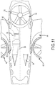
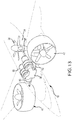
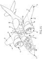
- the VTOL aircraft 10 includes a power plant and power transmission system that supplies power to the lift fan 32, the first lift/thrust fan 40, and second lift/thrust fan 42. It is contemplated that a single engine could be used to supply power to the VTOL aircraft 10. However, the depicted embodiments include a first engine 50 and second engine 52 that are positioned astride one another within the fuselage 12 between the first wing 20 and second wing 22. In one particular embodiment, the first engine 50 and second engine 52 are each at least comparable to an engine having maximum rated sea level power of over 2,000 shp.
- a pair of opposing NACA style air inlet ducts 54 penetrate the fuselage, forward from the first engine 50 and second engine 52.
- a pair of exhaust ports 56 pass from the first engine 50 and second engine 52 and penetrate the opposite sides of the central portion 18 of the fuselage 12.
- an exemplary power transmission system for use with the VTOL aircraft 10 includes a gear box 58 that receives the power output from the first engine 50 and second engine 52.
- a first output shaft 60 and second output shaft 62 extend transversely from the gear box 58 and engage a first reduction gear 64 and second reduction gear 66 associated with the first lift/thrust fan 40 and second lift/thrust fan 42, respectively.
- a third output shaft 68 extends rearwardly from the gear box 58 and engages a third reduction gear 69 associated with the lift fan 32.
- the output shafts described herein may be provided as dual, coaxial shafts, which provide redundancy to the power transmission system.
- the VTOL aircraft 10 includes flight control systems for operating the VTOL aircraft 10 through various flight operations. Aspects of the flight operations will be monitored, and in certain instances, directly controlled by a flight control computer.
- a processor associated with the flight control computer will receive data input from one or more associated systems.
- embodiments of the flight control systems include a plurality of pilot inputs, which transmit data to the flight control computer. These pilot inputs include, but are not limited to, pitch and roll commands from a flight control stick, yaw from rudder pedals, trim commands, and power commands from engine throttle controls.
- the flight control systems are operatively coupled with aircraft control surfaces that include elevators, ailerons, and a rudder.
- the flight control systems are operatively coupled with the ducted lift/thrust fans, and the lift fan in a manner that permits selective control over functions of the aircraft control surfaces, the ducted lift/thrust fans 40 and 42, and the lift fan 36.
- the flight control systems permit selective control of fan blade pitch, power, or rotational speeds of the ducted lift/thrust fans 40 and 42, and the lift fan 36.
- Embodiments of the VTOL aircraft 10 further include a motion sensor/accelerometer for measuring aircraft acceleration in the X, Y, and Z axis.
- a rate gyroscope may be provided to receive and relay data related to rotation angles of pitch, yaw, and roll.
- One or more sensors detect the retracted and deployed states of landing gear 70.
- Various peripheral systems provide environmental data to the flight control computer including an altimeter, an air data sensor system, a pitot-static probe, and a total temperature probe. The data from such peripheral systems is processed within the flight control computer, which may store such data within one or more associated memory storage systems.
- One or more displays or multi-functional displays relay the state of flight control to the flight crew.
- Embodiments of the VTOL aircraft 10 include an emergency parachute system for use where the VTOL aircraft 10 encounters complete or significant propulsion failure and has insufficient airspeed to perform a gliding emergency landing. Some such embodiments include one or more parachutes that would primarily be used while the VTOL aircraft 10 is in hover mode or travelling at slow speeds. Embodiments of the emergency parachute system secure the parachute within a compartment within the fuselage 12, adjacent its rearward end portion 16. Supporting parachutes cables are coupled to the airframe. In some embodiments, the emergency parachute is deployed by the pilot via a pilot input or is automatically deployed by a flight control computer if an engine loses power or the VTOL aircraft 10 becomes unstable in hover mode.
- the emergency parachute system deploys the rockets that shoot out at an angle from the fuselage 12 and pull the ends of the parachute in opposite directions, thereby deploying the canopy. If the VTOL aircraft 10 is traveling in forward flight, the flight control computer may be programed to receive data from one or more air sensors in order to determine if a need exists to delay deployment of the parachute where the speed is too great.
- first lift/thrust fan 40 When the thrust of the lift fan 32, first lift/thrust fan 40, and second lift/thrust fan 42 reach determined values or greater, the operator engages a hovering mode from a pilot input associated with the flight control system. The thrust of the lift fan 32, first lift/thrust fan 40, and second lift/thrust fan 42 are increased until the VTOL aircraft 10 lifts off.
- the operator selects a cruise mode from a pilot input associated with the flight control computer.
- a signal is sent from the flight control computer to gradually tilt the first lift/thrust fan 40 and second lift/thrust fan 42 from the first position to the second position in order to produce a forward moving force.
- lift force is generated on the wings and the VTOL aircraft 10 cruises with the thrust of the first lift/thrust fan 40 and second lift/thrust fan 42 directed backward.
- the operator may then execute manual operation by means of the control stick and steering pedals. Concurrently, or in the alternative, flight operations can be left to automatic operation performed based on data received from the peripheral sensors and systems associated with the flight control computer.
- the VTOL aircraft 10 provides a vertical takeoff and landing aircraft that can cruise with high speed and does not need a runway for taking off or landing because it may take off from, or land on, the ground vertically.
- the VTOL aircraft 10 has a total weight (empty) of less than 2267,96 kg (5000 pounds).
- Various embodiments afford the VTOL aircraft with a maximum VTOL takeoff weight of over 2721,55 kg (6000 pounds).
- Such embodiments of the VTOL aircraft 10 can, in less than 90 seconds from vertical takeoff, attain an altitude of approximately 609,6 m, 5,556 km (2000 feet, 3 nautical miles) down range, at a cruising speed of 240 kts true airspeed at a 10 degree climb angle.
- the VTOL aircraft 10 may also perform short (STOL) or conventional takeoffs and landings.
- Embodiments of the present technology permit takeoffs and landings of less than 213,4 m (700 feet) on a runway with the first lift/thrust fan 40 and second lift/thrust fan 42 in the first position (forward flight), with a maximum STOL takeoff weight of over 2267,96 kg (7000 pounds),
- the runway distance for takeoff may be shortened to approximately 91,44 m (300 feet) where the first lift/thrust fan 40 and second lift/thrust fan 42 are rotated up 40 degrees between the first position and the second position.
- the VTOL aircraft will provide an NBAA VFR range of 2222,4 km (1200 nautical miles) and an NBAA IFR range of 2037,2 km (1100 nautical miles, calculated at 240 KTAS cruise speed at an altitude of 8839,2 m (29000 feet)).
- a stated range of 1 to 10 should be considered to include and provide support for claims that recite any and all subranges or individual values that are between and/or inclusive of the minimum value of 1 and the maximum value of 10; that is, all subranges beginning with a minimum value of 1 or more and ending with a maximum value of 10 or less (e.g., 5.5 to 10, 2.34 to 3.56, and so forth) or any values from 1 to 10 (e.g., 3, 5.8, 9.9994, and so forth) .
Description
- This application claims the benefit of
U.S. Provisional Patent Application No. 61/989,935, filed May 7, 2014 - Airports are becoming increasingly necessary near urban areas to address the needs of commuters and other travel between cities. However, airports occupy a large footprint due to long runways and expansive air space needed for fixed wing aircraft to safely takeoff and land. Constructing such airports is also cost prohibitive for small and medium sized municipalities. Where large cities are better situated to afford the construction of airports, the noise, pollution and safety issues presented by urban airports is problematic. Accordingly, there is a long-felt need in the aviation industry for small, affordable, vertical takeoff and landing (VTOL) aircraft that may takeoff, land, and be stored, on relatively small parcels of commercial and residential real estate.
- Historically, the aviation industry believed that helicopters would fulfill the need for small, affordable, VTOL aircraft. Unfortunately, helicopters remain a special-purpose aircraft due to their control systems, their large-diameter rotors, and their slow speed and limited range. Helicopter control systems include complex mechanisms for continuously adjusting the rotor pitch. Such control systems are expensive to construct and to maintain. Moreover, helicopters are notoriously difficult to fly, requiring specialized flight training, particularly as compared to fixed-wing aircraft. Further, the large-diameter exposed rotors present serious safety and operational challenges. Helicopters also suffer from their limited ability to fly anywhere near the speed and range of fixed-wing aircraft. Accordingly, traditional helicopter technology is ill suited to address important operational and user needs and demands.
- Over the decades, there have been numerous attempts to combine the speed, range and comfort of a fixed-wing airplane with the VTOL and hover capability of a helicopter. However, except for two military aircraft, the British Harrier jet and the U.S. Air Force F-35, the tiltrotor category of aircraft is the only combined VTOL/fixed-wing aircraft which appears to be near FAA certification and commercial production. However, tiltrotors can only lift off and land vertically because the rotor blades would strike the ground in the forward flight configuration. Therefore, the gross weight of a tiltrotor aircraft is less than fixed-wing aircraft, which are capable of taking off on a runway. The large engine/rotor assemblies also diminish the aerodynamics of the wings to which they are secured. While this reduces performance, it further decreases safety where an emergent gliding landing is necessary. This is particularly problematic in tiltrotor aircraft where a gliding landing becomes necessary shortly after takeoff when the rotors are positioned vertically, and a "tilt-wing" aircraft when the rotors and wings are positioned vertically. Further, because of its size and complexity, the tiltrotor could not be the basis (from a physical or engineering standpoint) for a light, fast, compact, and affordable aircraft in the commercial market.
- There is another category of VTOL aircraft designed to reach high speeds - that is, helicopters with additional components to increase speed, such as propellers, known as "compound helicopters." Sikorsky's X2 technology aircraft and AVX Aircraft Company's coaxial rotor/dual ducted fan technology are included in this category. The Sikorsky and AVX aircraft arc not in commercial production, but arc designed to be capable of achieving high speed with VTOL and hovering capability superior to any fixed-wing aircraft except the tilt-rotor. However, similar to the tilt-rotor, these compound helicopters have standard large helicopter blades for lift during take-off and landing, rather than smaller safer ducted fans for lift during take-off and landing. Various prototype or experimental aircraft with rotating ducted fans were flown in the mid-20th century. However, the engines and fans didn't provide sufficient lift for cargo or passengers, and those aircraft experienced significant controllability problems.
- Many of these prior art VTOL aircraft designs suffer a wide array of similar disadvantages that have prevented their wide-spread acceptance as a day-to-day commuter aircraft. Another disadvantage is that many such designs require several times the horsepower to maintain the aircraft aloft, in takeoff and hover modes. Accordingly, such aircraft suffer from relatively high rates of fuel consumption, both while hovering and in forward, horizontal flight. VTOL designs with lift fans are known for example from the documents
US1783458 A ,WO 2010/137016 A2 ,US 1841815 A ,US 2009/114771 ,BE 407576 A CN 101643116 A . - This Summary is provided to introduce a selection of concepts in a simplified form that are further described below in the Detailed Description. This Summary, and the foregoing Background, is not intended to identify key aspects or essential aspects of the claimed subject matter. Moreover, this Summary is not intended for use as an aid in determining the scope of the claimed subject matter.
- Aircraft, according to the present technology, are fundamentally different from prior aircraft designs. In particular, embodiments of the present aircraft present fixed-wing, ducted fan, VTOL aircraft that use a uniquely configured set of triangulated, ducted fans. This provides aircraft that are practical, with competitive speed, range, and comfort for passengers, and a substantial payload capability.
- In various embodiments, the aircraft includes a fuselage having a forward end portion, a rearward end portion, and a central portion that extends between the forward end portion and rearward end portion. The fuselage defines a central longitudinal axis of the aircraft. A pair of wings extend laterally outward from the fuselage. A downwardly exhausting, ducted lift fan is disposed within the fuselage, between a pitch axis of the aircraft and the rearward end portion of the fuselage. At least one retractable and re-closeable cover that is selectively movable between open and closed positions with respect to the ducted lift fan. A pair of ducted lift/thrust fans are coupled with the pair of wings such that the fans are positioned symmetrically with one another on opposite sides of a roll axis of the aircraft, forward of the pitch axis. The pair of ducted lift/thrust fans are selectively, rotatably movable between a first position in which they provide vertical lift and a second position in which they provide horizontal thrust.
- The leading edge portions of each of the aircraft wings include a curvilinear fan recess. Each of the pair of ducted lift/thrust fans are rotatably disposed within a curvilinear fan recess. Accordingly, the curvilinear fan recesses are shaped to approximate a shape of a circumferential edge portion of the ducted lift/thrust fans. Embodiments of the aircraft position the ducted lift fan and the pair of ducted lift/thrust fans with respect to one another to be triangulated about a center of gravity for the aircraft. Thrust from each of the pair of ducted lift/thrust fans is independently controllable to provide roll control of the aircraft. Thrust from the lift fan in the rearward portion of the fuselage is controllable to provide pitch control of the aircraft.
- Embodiments of the aircraft include a power plant that is disposed within the fuselage and operatively coupled with the pair of ducted lift/thrust fans and the lift fan. In some such embodiments, the power plant includes a plurality of engines that are operatively coupled with a single power transmission system, which is coupled with the pair of ducted lift/thrust fans and the lift fan. A first output shaft and second output shaft extend transversely, in opposite directions from a gear box, which is operatively coupled with the plurality of engines, and are coupled with reduction gear boxes associated with the pair of ducted lift/thrust fans. A third output shaft extends rearwardly from the gearbox and is coupled with a reduction gear box associated with the rear lift fan contained in the fuselage.
- These and other aspects of the present system and method will be apparent after consideration of the Detailed Description and Figures herein. It is to be understood, however, that the scope of the invention shall be determined by the claims as issued and not by whether given subject matter addresses any or all issues noted in the Background or includes any features or aspects recited in this Summary.
- Non-limiting and non-exhaustive embodiments of the present invention, including the preferred embodiment, are described with reference to the following figures, wherein like reference numerals refer to like parts throughout the various views unless otherwise specified.
-
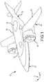
Figure 1 depicts a perspective view of one embodiment of the VTOL aircraft of the present technology and one manner in which the VTOL aircraft may be configured for forward flight. -
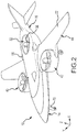
Figure 2 depicts a perspective view of the VTOL aircraft depicted inFigure 1 and depicts one manner in which the VTOL aircraft may be configured for landing or takeoff. -
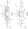
Figure 3 depicts a front elevation view of the VTOL aircraft depicted inFigure 1 . -
Figure 4 depicts a front elevation view of the VTOL aircraft depicted inFigure 2 . -
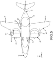
Figure 5 depicts a top plan view of the VTOL aircraft depicted inFigure 1 . -
Figure 6 depicts a top plan view of the VTOL aircraft depicted inFigure 2 . -
Figure 7 depicts a side elevation view of the VTOL aircraft depicted inFigure 1 . -
Figure 8 depicts a side elevation view of the VTOL aircraft depicted inFigure 2 . -
Figure 9 depicts a rear elevation view of the VTOL aircraft depicted inFigure 2 and further depicting an embodiment that employs vanes below the body fan for providing yaw control. -
Figure 10 depicts a perspective, cut-away view of the VTOL aircraft depicted inFigure 2 and further demonstrates one manner in which engines and their intakes and exhaust ports may be positioned with respect to the fuselage and ported fans of the VTOL aircraft. -
Figure 11 depicts a top plan, cut-away view of the VTOL aircraft depicted inFigure 10 . -
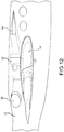
Figure 12 depicts a side elevation, cut-away view of the VTOL aircraft depicted inFigure 10 . -
Figure 13 depicts a perspective schematic view of an embodiment of the VTOL aircraft of the present technology and demonstrates one manner in which engines and transmission systems may be coupled with the ducted fans. -
Figure 14 depicts an isometric view of engines and a power transmission system configured for use with embodiments of the VTOL aircraft of the present technology. -
Figure 15 depicts a schematic perspective view of one embodiment of the VTOL of the present technology and one configuration of a passenger compartment. -
Figure 16 depicts a schematic perspective view of another embodiment of the VTOL of the present technology and an alternate configuration of a passenger compartment. - Embodiments are described more fully below with reference to the accompanying figures, which form a part hereof and show, by way of illustration, specific exemplary embodiments. These embodiments are disclosed in sufficient detail to enable those skilled in the art to practice the invention. However, embodiments may be implemented in many different forms and should not be construed as being limited to the embodiments set forth herein. The following detailed description is, therefore, not to be taken in a limiting sense.
- Embodiments of the present technology, as they relate to a
VTOL aircraft 10, are generally depicted inFigures 1-16 . With particular reference toFigures 1-9 ,15 , and16 , embodiments of theVTOL aircraft 10 include afuselage 12 having aforward end portion 14, arearward end portion 16, and acentral portion 18 that extends between theforward end portion 14 andrearward end portion 16. Various embodiments of thefuselage 12 are elongated, defining a central longitudinal roll axis X of theVTOL aircraft 10. In at least some embodiments, thefuselage 12 is provided with a length of 41 feet and a cabin width of 78 inches. In some embodiments, such as depicted inFigures 15 and16 , theforward end portion 14 of thefuselage 12 may be configured with a passenger and flight control compartment. In various embodiments, such as depicted inFigure 15 , the passenger and flight control compartment may be configured for a total of five people. This may include a flight crew of between one and two people and three to four passengers. Aft of the passenger and flight control compartment, theVTOL aircraft 10 may include a storage or payload compartment. In other embodiments, the VTOL aircraft may be increased in size to accommodate a greater number of individuals and/or payload. For example,Figure 16 depicts one embodiment where the passenger and flight control compartment may be configured for a total of six people. This may include a flight crew of between one and two people and four to five passengers. - A pair of wings and, in particular a
first wing 20 andsecond wing 22, are secured in a fixed position with respect to thefuselage 12. Thefirst wing 20 andsecond wing 22 are each defined by a leading edge portion 24, a trailingedge portion 26, aroot end 28, and an oppositetip end portion 30. The root ends 28 of thefirst wing 20 andsecond wing 22 are respectively coupled with thecentral portions 18 of thefuselage 12, such that thefirst wing 20 andsecond wing 22 extend laterally outward from thefuselage 12. In at least some embodiments, thefirst wing 20 andsecond wing 22 are of a swept wing design, providing the VTOL aircraft with a wing span of 38 feet and a wing area of approximately 240 square feet. In certain embodiments, the wings provide theVTOL aircraft 10 with a stall speed of less than 80 kts. - With reference to
Figures 2 and6 , various embodiments of theVTOL aircraft 10 include a downwardly exhausting,ducted lift fan 32 that is disposed within thefuselage 12, between a pitch axis Z of theVTOL aircraft 10 and therearward end portion 16 of thefuselage 12. As this term is used herein, a "ducted fan" is simply a system that accelerates air as it passes through a duct or shroud. The duct serves primarily to induce additional air mass flow through the fan blades than would occur without the duct. This increases the "thrust", which is the force of reaction to the acceleration of air, as compared to a non-ducted fan or propeller. With specific reference toFigures 2 and6 , air is accelerated through thehorizontal duct 34 by amulti-bladed fan 36. In the depicted embodiment, thehorizontal duct 34 is defined as an opening that penetrates thefuselage 12, behind the pitch axis Z of theVTOL aircraft 10 and forward from therearward end portion 16 of thefuselage 12. It is contemplated that thehorizontal duct 34 and thefuselage 12 could be formed of unitary construction or as separate structures that are secured in a fixed position with respect to one another. - With reference to
Figures 1 ,2 ,5 ,6 , and9 , a set of hinged "clam shell" door covers orlouvers 37 may be associated with the bottom outlet opening of thehorizontal duct 34 and aretractable cover 38 may be associated with the top inlet opening. The bottom door covers 37 andretractable cover 38 will be provided, in various embodiments, to selectively move between open positions (depicted inFigures 1 and5 ) and closed positions (depicted inFigures 2 and6 ). In particular, the bottom door covers 37 and theretractable cover 38 will be disposed in the open position where thelift fan 36 is operated to produce lifting thrust through thehorizontal duct 34. In some embodiments, the bottom door covers 37 and theretractable cover 38 will be placed in the closed position when the VTOL aircraft is operated in forward flight, where lifting thrust from thefan 36 is not desired or needed. It is contemplated that the bottom door covers 37 and theretractable cover 38 may be provided in a plurality of components that retract fore and aft or in opposite, lateral directions. A one-pieceretractable cover 38 may also be used that retracts fore or aft on various known methods. In still another embodiment, it is contemplated that the bottom door covers 37 andretractable cover 38 may be provided as a plurality of louvers that rotate between closed and substantially open positions. In one such embodiment, one ormore louvers 39 are pivotably coupled directly beneath thelift fan 36 and movable between open and closed positions and discreet points therebetween. In the closed position, thelouvers 39 form a part of the bottom door covers 37 to close the bottom outlet opening of thehorizontal duct 34. This reduces the size of the outboard panels of the bottom door covers 37. Thelouvers 39 are disposed in an open position during hovering flight of theVTOL aircraft 10. Operative mechanical or electronic coupling of thelouvers 39 and flight controls, such as rudder pedals or the like, enable selective angular disposition of the louvers when in the open position. Selective angular position beneath the bottom outlet opening of thehorizontal duct 34 may be used to deflect the thrust output of thehorizontal duct 34 and provide theVTOL aircraft 10 with an aspect of yaw control. - With reference to
Figures 1-8 , embodiments of theVTOL aircraft 10 include a pair of ducted lift/thrust fans. In particular, the depicted embodiments include a first lift/thrust fan 40 and second lift/thrust fan 42 that are respectively coupled with thefirst wing 20 andsecond wing 22. In various embodiments, the first lift/thrust fan 40 and second lift/thrust fan 42 include a 1,83 m (six foot) diameter, five blade rotor 41. Embodiments of the rotors 41 are rated for over 514,8 kW (700 hp). It is contemplated that the size of the rotor 41 may increase or decrease according to the dimensions and desired performance characteristics for theVTOL aircraft 10. In some embodiments, the pitch of the blades within the rotors 41 may be varied on demand according to the desired output performance. Thrust from each of the lift/thrust fans - The first lift/
thrust fan 40 and second lift/thrust fan 42 are positioned symmetrically with one another on opposite sides of a roll axis X of theVTOL aircraft 10 and forward of the pitch axis Z. In this manner, thelift fan 32 and the pair of ducted lift/thrust fans first wing 20 andsecond wing 22; a center of lift for thelift fan 32 and the ducted lift/thrust fans VTOL aircraft 10. The first lift/thrust fan 40 and second lift/thrust fan 42 are coupled with thefirst wing 20 andsecond wing 22 such that they are selectively, rotatably movable between a first position in which they provide vertical lift (Figure 2 ) and a second position in which they provide horizontal thrust (Figure 1 ). In some embodiments, the first lift/thrust fan 40 and second lift/thrust fan 42 are rotated between the first and second positions using mechanical, hydraulic, or electromechanical actuators capable of inducing movement, while being subjected to significant forces external, as well as locking the assembly in a single position when desired. - In the depicted embodiments, leading
edge portions 44 of each of thefirst wing 20 andsecond wing 22 include acurvilinear fan recess 46. Each of the first lift/thrust fan 40 and second lift/thrust fan 42 are rotatably disposed within acurvilinear fan recess 46. As depicted, embodiments of the present technology shape the curvilinear fan recesses 46 to approximate a shape of a circumferential edge portion of the first lift/thrust fan 40 and second lift/thrust fan 42. In this manner, the first lift/thrust fan 40 and second lift/thrust fan 42 may be horizontally disposed to nest within the curvilinear fan recesses 46. Thecurvilinear recesses 46 allow the first lift/thrust fan 40 and second lift/thrust fan 42 to be located aft, closely adjacent the pitch axis Z of theVTOL aircraft 10. Theleading edge portions 44 include opposing pairs of mountingshoulders 48 that project forward to pivotably engage the first lift/thrust fan 40 and second lift/thrust fan 42 approximate axial pivot points on the first lift/thrust fan 40 and second lift/thrust fan 42. In some embodiments, thefirst wing 20 andsecond wing 22 are provided with an aft sweep. This enables the first lift/thrust fan 40 and second lift/thrust fan 42 to be positioned intermediate the aroot end 28 and an oppositetip end portion 30 of thefirst wing 20 andsecond wing 22. As the position of the first lift/thrust fan 40 and second lift/thrust fan 42 move inwardly from thetip end portions 30 of thefirst wing 20 and second wing 22 a less structurally robust support is required throughout thefirst wing 20 andsecond wing 22, which reduces overall weight of theVTOL aircraft 10. - With reference to
Figures 10-14 , theVTOL aircraft 10 includes a power plant and power transmission system that supplies power to thelift fan 32, the first lift/thrust fan 40, and second lift/thrust fan 42. It is contemplated that a single engine could be used to supply power to theVTOL aircraft 10. However, the depicted embodiments include afirst engine 50 andsecond engine 52 that are positioned astride one another within thefuselage 12 between thefirst wing 20 andsecond wing 22. In one particular embodiment, thefirst engine 50 andsecond engine 52 are each at least comparable to an engine having maximum rated sea level power of over 2,000 shp. As depicted inFigures 10 and11 , a pair of opposing NACA styleair inlet ducts 54 penetrate the fuselage, forward from thefirst engine 50 andsecond engine 52. A pair ofexhaust ports 56 pass from thefirst engine 50 andsecond engine 52 and penetrate the opposite sides of thecentral portion 18 of thefuselage 12. - With further reference to
Figure 14 , an exemplary power transmission system for use with theVTOL aircraft 10 includes agear box 58 that receives the power output from thefirst engine 50 andsecond engine 52. In the depicted embodiment, afirst output shaft 60 andsecond output shaft 62 extend transversely from thegear box 58 and engage afirst reduction gear 64 andsecond reduction gear 66 associated with the first lift/thrust fan 40 and second lift/thrust fan 42, respectively. Athird output shaft 68 extends rearwardly from thegear box 58 and engages a third reduction gear 69 associated with thelift fan 32. In various embodiments, it is contemplated that the output shafts described herein may be provided as dual, coaxial shafts, which provide redundancy to the power transmission system. - The
VTOL aircraft 10 includes flight control systems for operating theVTOL aircraft 10 through various flight operations. Aspects of the flight operations will be monitored, and in certain instances, directly controlled by a flight control computer. A processor associated with the flight control computer will receive data input from one or more associated systems. For example, embodiments of the flight control systems include a plurality of pilot inputs, which transmit data to the flight control computer. These pilot inputs include, but are not limited to, pitch and roll commands from a flight control stick, yaw from rudder pedals, trim commands, and power commands from engine throttle controls. In various embodiments, the flight control systems are operatively coupled with aircraft control surfaces that include elevators, ailerons, and a rudder. In some embodiments, the flight control systems are operatively coupled with the ducted lift/thrust fans, and the lift fan in a manner that permits selective control over functions of the aircraft control surfaces, the ducted lift/thrust fans lift fan 36. In some such embodiments, the flight control systems permit selective control of fan blade pitch, power, or rotational speeds of the ducted lift/thrust fans lift fan 36. Embodiments of theVTOL aircraft 10 further include a motion sensor/accelerometer for measuring aircraft acceleration in the X, Y, and Z axis. A rate gyroscope may be provided to receive and relay data related to rotation angles of pitch, yaw, and roll. One or more sensors detect the retracted and deployed states oflanding gear 70. Various peripheral systems provide environmental data to the flight control computer including an altimeter, an air data sensor system, a pitot-static probe, and a total temperature probe. The data from such peripheral systems is processed within the flight control computer, which may store such data within one or more associated memory storage systems. One or more displays or multi-functional displays relay the state of flight control to the flight crew. - Embodiments of the
VTOL aircraft 10 include an emergency parachute system for use where theVTOL aircraft 10 encounters complete or significant propulsion failure and has insufficient airspeed to perform a gliding emergency landing. Some such embodiments include one or more parachutes that would primarily be used while theVTOL aircraft 10 is in hover mode or travelling at slow speeds. Embodiments of the emergency parachute system secure the parachute within a compartment within thefuselage 12, adjacent itsrearward end portion 16. Supporting parachutes cables are coupled to the airframe. In some embodiments, the emergency parachute is deployed by the pilot via a pilot input or is automatically deployed by a flight control computer if an engine loses power or theVTOL aircraft 10 becomes unstable in hover mode. In some embodiments, the emergency parachute system deploys the rockets that shoot out at an angle from thefuselage 12 and pull the ends of the parachute in opposite directions, thereby deploying the canopy. If theVTOL aircraft 10 is traveling in forward flight, the flight control computer may be programed to receive data from one or more air sensors in order to determine if a need exists to delay deployment of the parachute where the speed is too great. - The flight control systems of the
VTOL aircraft 10, as described above, simplify vertical takeoff and landing operations as well as the transitions between hovering modes and forward flight. For example, an operator initiates a vertical takeoff by positioning the lift/thrust fans in the first, takeoff position so that the thrust thereof directs toward the ground as shown inFigure 2 . The operator engages a pilot input to initiate a start mode. Data received within the flight control computer actuates the bottom door covers 37 andretractable covers 38 to move into open positions. Start sequences are then initiated for thelift fan 32, first lift/thrust fan 40, and second lift thrust/fan 42. The flight control system allows the fans to reach an idling state. When the thrust of thelift fan 32, first lift/thrust fan 40, and second lift/thrust fan 42 reach determined values or greater, the operator engages a hovering mode from a pilot input associated with the flight control system. The thrust of thelift fan 32, first lift/thrust fan 40, and second lift/thrust fan 42 are increased until theVTOL aircraft 10 lifts off. - With the
VTOL aircraft 10 hovering in a stable manner, the operator selects a cruise mode from a pilot input associated with the flight control computer. A signal is sent from the flight control computer to gradually tilt the first lift/thrust fan 40 and second lift/thrust fan 42 from the first position to the second position in order to produce a forward moving force. As theVTOL aircraft 10 accelerates into forward flight, lift force is generated on the wings and theVTOL aircraft 10 cruises with the thrust of the first lift/thrust fan 40 and second lift/thrust fan 42 directed backward. The operator may then execute manual operation by means of the control stick and steering pedals. Concurrently, or in the alternative, flight operations can be left to automatic operation performed based on data received from the peripheral sensors and systems associated with the flight control computer. - The
VTOL aircraft 10, of the present technology, provides a vertical takeoff and landing aircraft that can cruise with high speed and does not need a runway for taking off or landing because it may take off from, or land on, the ground vertically. In at least some embodiments, theVTOL aircraft 10 has a total weight (empty) of less than 2267,96 kg (5000 pounds). Various embodiments afford the VTOL aircraft with a maximum VTOL takeoff weight of over 2721,55 kg (6000 pounds). Such embodiments of theVTOL aircraft 10 can, in less than 90 seconds from vertical takeoff, attain an altitude of approximately 609,6 m, 5,556 km (2000 feet, 3 nautical miles) down range, at a cruising speed of 240 kts true airspeed at a 10 degree climb angle. When desired, theVTOL aircraft 10 may also perform short (STOL) or conventional takeoffs and landings. Embodiments of the present technology permit takeoffs and landings of less than 213,4 m (700 feet) on a runway with the first lift/thrust fan 40 and second lift/thrust fan 42 in the first position (forward flight), with a maximum STOL takeoff weight of over 2267,96 kg (7000 pounds), The runway distance for takeoff may be shortened to approximately 91,44 m (300 feet) where the first lift/thrust fan 40 and second lift/thrust fan 42 are rotated up 40 degrees between the first position and the second position. In such embodiments, the VTOL aircraft will provide an NBAA VFR range of 2222,4 km (1200 nautical miles) and an NBAA IFR range of 2037,2 km (1100 nautical miles, calculated at 240 KTAS cruise speed at an altitude of 8839,2 m (29000 feet)). - Although the technology has been described in language that is specific to certain structures, materials, and methodological steps, it is to be understood that the invention defined in the appended claims is not necessarily limited to the specific structures, materials, and/or steps described. Rather, the specific aspects and steps are described as forms of implementing the claimed invention. Since many embodiments of the invention can be practiced without departing from the scope of the invention, the invention resides in the claims hereinafter appended. Moreover, all ranges disclosed herein are to be understood to encompass and provide support for claims that recite any and all subranges or any and all individual values subsumed therein. For example, a stated range of 1 to 10 should be considered to include and provide support for claims that recite any and all subranges or individual values that are between and/or inclusive of the minimum value of 1 and the maximum value of 10; that is, all subranges beginning with a minimum value of 1 or more and ending with a maximum value of 10 or less (e.g., 5.5 to 10, 2.34 to 3.56, and so forth) or any values from 1 to 10 (e.g., 3, 5.8, 9.9994, and so forth) .
Claims (15)
- An aircraft (10) capable of vertical takeoff and landing, the aircraft comprising:a fuselage (12) having a forward end portion (14), a rearward end portion (16), and a central portion (18) that extends between the forward end portion (14) and the rearward end portion (16); the fuselage (12) defining a central longitudinal axis of the aircraft (10);a pair of wings (20,22), each having: a leading edge portion (24); a trailing edge portion (26); a root end (28) respectively coupled with the central portion (18) of the fuselage (12); and an opposite tip end portion (30) extending laterally outward from the fuselage (12); the leading edge portions (44) of each of the wings (20,22) include a curvilinear fan recess (46);a pair of ducted lift/thrust fans (40,42) respectively coupled with one of the pair of wings (20,22) such that the fans (40,42) are positioned symmetrically with one another on opposite sides of a roll axis of the aircraft and forward of a pitch axis of the aircraft; the pair of ducted lift/thrust fans (40,42) being selectively, rotatably movable between a first position in which they provide vertical lift and a second position in which they provide horizontal thrust; each of the pair of ducted lift/thrust fans (40,42) respectively, rotatably disposed within the curvilinear fan recess (46), wherein the curvilinear fan recesses (46) are shaped to approximate a shape of a circumferential edge portion of the ducted lift/thrust fans (40,42) the leading edge portions (44) including opposing pairs of mounting shoulders (48) that project forward to pivotably engage the first lift/thrust fan (40) and second lift/thrust fan (42) proximate axial pivot points on the first lift/thrust fan (40) and second lift/thrust fan (40), the first wing (20) and the second wing (22) are provided with an aft sweep; the first lift/thrust fan (40) and second lift/thrust fan (42) are positioned intermediate the root end (28) and the opposite tip end portion (30) of the first wing (20) and the second wing (22); anda downwardly exhausting, ducted lift fan (32) disposed within the fuselage (12), between the pitch axis and the rearward end portion (16) of the fuselage (12), whereby the rearward end portion (16) of the fuselage (12) extends rearwardly from the ducted lift fan (32).
- The aircraft (10) of claim 1 wherein the leading edge portions (44) of each of the wings (20,22) are aft swept to align a lift from the pair of ducted lift/thrust fans (40,42) and the ducted lift fan (32) with a lift of the wings (20,22).
- The aircraft (10) of claim 1 wherein the ducted lift fan (32) and the pair of ducted lift/thrust fans (40,42) are positioned with respect to one another to be triangulated about a center of gravity for the aircraft (10).
- The aircraft (10) of claim 1 wherein the ducted lift fan (32) and the pair of ducted lift/thrust fans (40,42) are positioned with respect to one another to be triangulated about a center of lift for the pair of wings (20,22).
- The aircraft (10) of claim 1 wherein the ducted lift fan (32) and the pair of ducted lift/thrust fans (40,42) are positioned with respect to one another to be triangulated about a center of lift for the ducted lift fan (32) and the pair of ducted lift/thrust fans (40,42).
- The aircraft (10) of claim 1 wherein thrust from each of the pair of ducted lift/thrust fans is independently controllable.
- The aircraft (10) of claim 1 further comprising at least one cover (37,38) that is selectively movable between open and closed positions with respect to the ducted lift fan (32).
- The aircraft (10) of claim 7 wherein the at least one cover (37,38) includes at least one louver (37) that is positioned beneath the ducted lift fan (32) and in line with a thrust output of the ducted lift fan; the at least one louver (37) being selectively, pivotably movable along various degrees between the open and closed positions with respect to the ducted lift fan (32), such that the thrust output is selectively, angularly directed, to provide yaw control for the aircraft.
- The aircraft (10) of claim 8 wherein the at least one louver (37) combines with at least one selectively movable outboard bottom door to define a bottom door cover (37) for the ducted lift fan (32).
- The aircraft (10) of claim 1 further comprising a power plant disposed within the fuselage (12), the power plant being operatively coupled with the pair of ducted lift/thrust fans (40,42) and the lift fan (32); the power plant including a plurality of engines (50,52)
that are operatively coupled with a single power transmission system that is coupled with the pair of ducted lift/thrust fans (40,42) and the lift fan (32). - The aircraft (10) of claim 10 wherein a first output shaft (60) and second output shaft (62) extend transversely, in opposite directions from a gear box (58), which is operatively coupled with the plurality of engines (50,52), and are coupled with reduction gear boxes associated with the pair of ducted lift/thrust fans (40,42); a third output shaft (68) extends rearwardly from the gearbox (58) and is coupled with a reduction gear box associated with the rear lift fan contained in the fuselage.
- The aircraft (10) of claim 1 wherein the pitch control of the aircraft is effected by varying the power distributed to the ducted lift/thrust fans (40,42) and lift fan (32) by increased fan blade pitch or increased fan rotational velocity.
- The aircraft (10) of claim 1 wherein the roll control of the aircraft is effected by varying the power distributed to the ducted lift/thrust fans (40,42) by increased fan blade pitch or increased fan rotational velocity.
- The aircraft (10) of claim 1 further comprising:
flight control systems operatively coupled with aircraft control surfaces, the ducted lift/thrust fans (40,42), and the lift fan (32) in a manner that permits selective control over functions of the aircraft control surfaces, the ducted lift/thrust fans (40,42), and the lift fan (32). - The aircraft (10) of claim 14 wherein the flight control systems permit selective control of fan blade pitch, power, or rotational speeds of the ducted lift/thrust fans (40,42) and the lift fan (32).
Applications Claiming Priority (2)
| Application Number | Priority Date | Filing Date | Title |
|---|---|---|---|
| US201461989935P | 2014-05-07 | 2014-05-07 | |
| PCT/US2015/029751 WO2016018486A2 (en) | 2014-05-07 | 2015-05-07 | Vtol aircraft |
Publications (3)
| Publication Number | Publication Date |
|---|---|
| EP3140190A2 EP3140190A2 (en) | 2017-03-15 |
| EP3140190A4 EP3140190A4 (en) | 2018-01-17 |
| EP3140190B1 true EP3140190B1 (en) | 2021-12-29 |
Family
ID=55218435
Family Applications (1)
| Application Number | Title | Priority Date | Filing Date |
|---|---|---|---|
| EP15827223.7A Active EP3140190B1 (en) | 2014-05-07 | 2015-05-07 | Vtol aircraft |
Country Status (7)
| Country | Link |
|---|---|
| US (1) | US9676479B2 (en) |
| EP (1) | EP3140190B1 (en) |
| JP (1) | JP6191039B2 (en) |
| CN (2) | CN111498109B (en) |
| BR (1) | BR112016025875B1 (en) |
| CA (1) | CA2947974C (en) |
| WO (1) | WO2016018486A2 (en) |
Families Citing this family (80)
| Publication number | Priority date | Publication date | Assignee | Title |
|---|---|---|---|---|
| KR101287624B1 (en) * | 2013-02-25 | 2013-07-23 | 주식회사 네스앤텍 | Unmanned aerial vehicle for easily landing |
| WO2016018486A2 (en) * | 2014-05-07 | 2016-02-04 | XTI Aircraft Company | Vtol aircraft |
| US10710713B2 (en) * | 2014-07-18 | 2020-07-14 | Pegasus Universal Aerospace (Pty) Ltd. | Vertical take-off and landing aircraft |
| US9889924B2 (en) * | 2015-08-24 | 2018-02-13 | The Boeing Company | Multi-directional control using upper surface blowing systems |
| US9908615B2 (en) * | 2015-10-26 | 2018-03-06 | Sikorsky Aircraft Corporation | Rotor blown wing aircraft including a rotor blown wing having at least one selectively controllable control surface and a method of controlling a rotor blown wing aircraft |
| US9856018B2 (en) * | 2016-01-11 | 2018-01-02 | The Boeing Company | Ducted fan doors for aircraft |
| US10926874B2 (en) * | 2016-01-15 | 2021-02-23 | Aurora Flight Sciences Corporation | Hybrid propulsion vertical take-off and landing aircraft |
| CN105711831B (en) * | 2016-04-25 | 2018-03-06 | 长江大学 | The fixed-wing unmanned plane of VTOL |
| US10106253B2 (en) * | 2016-08-31 | 2018-10-23 | Bell Helicopter Textron Inc. | Tilting ducted fan aircraft generating a pitch control moment |
| US10377480B2 (en) | 2016-08-10 | 2019-08-13 | Bell Helicopter Textron Inc. | Apparatus and method for directing thrust from tilting cross-flow fan wings on an aircraft |
| US10421541B2 (en) | 2016-08-10 | 2019-09-24 | Bell Helicopter Textron Inc. | Aircraft with tilting cross-flow fan wings |
| US10479495B2 (en) | 2016-08-10 | 2019-11-19 | Bell Helicopter Textron Inc. | Aircraft tail with cross-flow fan systems |
| US10279900B2 (en) | 2016-08-10 | 2019-05-07 | Bell Helicopter Textron Inc. | Rotorcraft variable thrust cross-flow fan systems |
| US10293931B2 (en) | 2016-08-31 | 2019-05-21 | Bell Helicopter Textron Inc. | Aircraft generating a triaxial dynamic thrust matrix |
| US10562623B1 (en) | 2016-10-21 | 2020-02-18 | Birdseyeview Aerobotics, Llc | Remotely controlled VTOL aircraft |
| GB2555440A (en) * | 2016-10-27 | 2018-05-02 | Mono Aerospace Ip Ltd | Vertical take off and landing aircraft |
| US10513333B2 (en) * | 2017-01-14 | 2019-12-24 | Spydar Sensors, Inc. | Ducted fan propulsion engine |
| US10384776B2 (en) | 2017-02-22 | 2019-08-20 | Bell Helicopter Textron Inc. | Tiltrotor aircraft having vertical lift and hover augmentation |
| US10676187B2 (en) * | 2017-03-07 | 2020-06-09 | The Boeing Company | Robust amphibious aircraft |
| JP7037826B2 (en) * | 2017-04-18 | 2022-03-17 | インダストリーネットワーク株式会社 | Propeller type flying object |
| TWI625270B (en) * | 2017-04-19 | 2018-06-01 | 威拓動力有限公司 | Triaxial helicopter |
| US11111033B1 (en) | 2017-05-12 | 2021-09-07 | Phirst Technologies, Llc | Unmanned aerial vehicle recharging system |
| WO2018209319A1 (en) * | 2017-05-12 | 2018-11-15 | Gencore Candeo, Ltd. | Systems and methods for response to emergency situations using unmanned airborne vehicles with improved functionalities |
| TWI627104B (en) * | 2017-05-31 | 2018-06-21 | 大鵬航太有限公司 | Simple Pitch Control Device for Dual-Mode Aircraft with VTOL and Fixed-Wing Flight |
| US20180346112A1 (en) * | 2017-05-31 | 2018-12-06 | Hsun-Yin Chiang | Simple pitch control device for dual-mode aircraft with vtol and fixed-wing flight |
| US10822101B2 (en) | 2017-07-21 | 2020-11-03 | General Electric Company | Vertical takeoff and landing aircraft having a forward thrust propulsor |
| CN107512393A (en) * | 2017-08-09 | 2017-12-26 | 深圳中翼特种装备制造有限公司 | A kind of rapid vertical landing fixed-wing unmanned plane |
| US10814967B2 (en) | 2017-08-28 | 2020-10-27 | Textron Innovations Inc. | Cargo transportation system having perimeter propulsion |
| JP6879866B2 (en) * | 2017-08-28 | 2021-06-02 | 本田技研工業株式会社 | Vertical takeoff and landing aircraft |
| CN107539472A (en) * | 2017-09-29 | 2018-01-05 | 清华大学 | A kind of single lift culvert vertical take-off and landing aircraft based on tilting duct |
| CN107628244A (en) * | 2017-09-29 | 2018-01-26 | 清华大学 | A kind of double lift culvert vertical take-off and landing aircrafts based on tilting duct |
| WO2019062256A1 (en) * | 2017-09-29 | 2019-04-04 | 清华大学 | Single lift force ducted vertical take-off and landing aircraft based on tilt duct |
| US11001384B2 (en) * | 2017-10-02 | 2021-05-11 | Bell Helicopter Textron Inc. | Hybrid power systems for aircraft |
| EP3470332B1 (en) | 2017-10-13 | 2020-04-22 | AIRBUS HELICOPTERS DEUTSCHLAND GmbH | A multirotor aircraft with an airframe and at least one wing |
| CN107640318A (en) * | 2017-10-15 | 2018-01-30 | 天津飞眼无人机科技有限公司 | Oil electric mixed dynamic fixed-wing unmanned plane |
| CN108082466A (en) * | 2017-11-23 | 2018-05-29 | 北京航空航天大学 | A kind of tilting duct connection wing layout vertically taking off and landing flyer |
| EP3724071B1 (en) * | 2017-12-12 | 2023-09-13 | Spencer, Cameron | Variable-geometry vertical take-off and landing (vtol) aircraft system |
| DE102017130809A1 (en) * | 2017-12-20 | 2019-06-27 | Airbus Defence and Space GmbH | Device for driving an aircraft and aircraft comprising this device |
| WO2019124686A1 (en) * | 2017-12-21 | 2019-06-27 | 한국항공우주연구원 | Method and computer program for controlling tilt angle of main rotor on basis of vertical attitude control signal low-speed flight state, and vertical take-off and landing aircraft |
| KR102010424B1 (en) | 2017-12-21 | 2019-08-14 | 한국항공우주연구원 | A method and computer program for controlling the tilt angle of the main rotor based on the pitch attitude control signal in the low speed region |
| CN108109473A (en) * | 2018-02-02 | 2018-06-01 | 安徽英釜航空科技有限公司 | A kind of flight simulator foot rudder linkage |
| CN108163191A (en) * | 2018-02-24 | 2018-06-15 | 金羽飞 | Aircraft |
| CN108298074A (en) * | 2018-03-14 | 2018-07-20 | 长沙市云智航科技有限公司 | The component that verts for the more rotor flying vehicles of manned duct |
| WO2019210128A2 (en) * | 2018-04-27 | 2019-10-31 | Aai Corporation | Variable pitch rotor assembly for electrically driven vectored thrust aircraft applications |
| US10933991B2 (en) * | 2018-06-18 | 2021-03-02 | Aurora Flight Sciences Corporation | Propulsors, aircraft including the propulsors, and methods of directing a fluid stream in a propulsor |
| DE102018116154B4 (en) * | 2018-07-04 | 2022-09-01 | Dr. Ing. H.C. F. Porsche Aktiengesellschaft | aircraft |
| US11926429B2 (en) * | 2018-07-04 | 2024-03-12 | Dr. Ing. H.C. F. Porsche Aktiengesellschaft | Aircraft having cooling system for distributing heat transfer liquid to different regions of aircraft |
| DE102018116168A1 (en) * | 2018-07-04 | 2020-01-09 | Dr. Ing. H.C. F. Porsche Aktiengesellschaft | aircraft |
| DE102018116147A1 (en) * | 2018-07-04 | 2020-01-09 | Dr. Ing. H.C. F. Porsche Aktiengesellschaft | aircraft |
| CN110723284A (en) * | 2018-07-17 | 2020-01-24 | 刘建国 | Vertical lifting fixed wing aircraft with tiltable ducted fan |
| US10829199B2 (en) * | 2018-08-20 | 2020-11-10 | Bell Helicopter Textron Inc. | Active airflow management for tiltrotor hub thermal ventilation |
| WO2020097367A1 (en) * | 2018-11-09 | 2020-05-14 | Karem Aircraft, Inc. | Vertical flight aircraft with improved stability |
| US11148799B2 (en) * | 2018-11-26 | 2021-10-19 | Textron Innovations Inc. | Tilting duct compound helicopter |
| US10787255B2 (en) * | 2018-11-30 | 2020-09-29 | Sky Canoe Inc. | Aerial vehicle with enhanced pitch control and interchangeable components |
| US20200216189A1 (en) * | 2019-01-03 | 2020-07-09 | Bell Textron Inc. | Display system |
| EP3730404B1 (en) * | 2019-04-23 | 2021-08-18 | LEONARDO S.p.A. | Vertical take-off and landing aircraft and related control method |
| WO2020225815A1 (en) * | 2019-05-07 | 2020-11-12 | Nft Inc. | Drive and fly electric and hybrid vtol vehicle |
| DE102019112132A1 (en) * | 2019-05-09 | 2020-11-12 | Dr. Ing. H.C. F. Porsche Aktiengesellschaft | Aircraft |
| CN110155315A (en) * | 2019-06-09 | 2019-08-23 | 西北工业大学 | A kind of unmanned vertical flight and its flight control method of oil electric mixed dynamic driving |
| US11536565B2 (en) * | 2019-06-21 | 2022-12-27 | Textron Innovations Inc. | System and method for gimbal lock avoidance in an aircraft |
| US11656632B2 (en) * | 2019-07-12 | 2023-05-23 | The Boeing Company | Takeoff/landing stability augmentation by active wind gust sensing |
| US11661193B2 (en) * | 2019-07-18 | 2023-05-30 | Elroy Air, Inc. | Unmanned aerial vehicle optimization |
| US11427313B2 (en) | 2019-10-15 | 2022-08-30 | Helmuth G. Bachmann | Universally attachable hinged wing and VLOS aid for mutirotor drones |
| CN111017205A (en) * | 2019-12-24 | 2020-04-17 | 中国航空工业集团公司西安飞机设计研究所 | Vertical take-off and landing conveyor |
| USD1009696S1 (en) | 2020-02-18 | 2024-01-02 | Aurora Flight Sciences Corporation, a subsidiary of The Boeing Company | Aircraft |
| US11554865B2 (en) * | 2020-02-18 | 2023-01-17 | Aurora Flight Sciences Corporation | Vertical take-off and landing (VTOL) aircraft and related methods |
| USD945947S1 (en) | 2020-02-24 | 2022-03-15 | Aurora Flight Sciences Corporation | Aircraft |
| US11472546B2 (en) | 2020-02-24 | 2022-10-18 | Aurora Flight Sciences Corporation | Fixed-wing short-takeoff-and-landing aircraft and related methods |
| CN111422348B (en) * | 2020-04-02 | 2021-11-16 | 沈阳航空航天大学 | Vertical take-off and landing unmanned aerial vehicle and control method thereof |
| CN111907274B (en) * | 2020-07-22 | 2023-09-08 | 淮阴工学院 | Ducted fan opening and closing device and application method thereof |
| CN112124569B (en) * | 2020-09-17 | 2022-04-01 | 西安电子科技大学 | Vertical take-off and landing and unmanned aerial vehicle stabilizing system based on launching canister |
| CN112373702B (en) * | 2020-11-24 | 2022-07-05 | 中国航空发动机研究院 | Back-support type wing-body fusion body aircraft propulsion system and control method thereof |
| WO2022113086A1 (en) * | 2020-11-30 | 2022-06-02 | Efix Aviation Ltd | Rotorcraft |
| CN112340013A (en) * | 2020-12-12 | 2021-02-09 | 江西洪都航空工业股份有限公司 | Fixed wing aircraft with tiltable duct |
| DE102020007834A1 (en) | 2020-12-21 | 2022-06-23 | BAAZ GmbH | Aircraft and associated operating procedures |
| US11772773B2 (en) | 2021-01-04 | 2023-10-03 | Aurora Flight Sciences Corporation, a subsidiary of The Boeing Company | Aircraft and related methods |
| CN112896500A (en) * | 2021-03-08 | 2021-06-04 | 四川腾盾科技有限公司 | Aircraft with four ducts in tilting layout |
| US11447244B1 (en) | 2021-06-29 | 2022-09-20 | Beta Air, Llc | System and method for airspeed estimation utilizing propulsor data in electric vertical takeoff and landing aircraft |
| CN114194388A (en) * | 2021-11-23 | 2022-03-18 | 上海羽天航空科技有限公司 | Novel vertical take-off and landing fixed wing aircraft |
| US11859542B2 (en) * | 2021-12-20 | 2024-01-02 | Rolls-Royce North American Technologies, Inc. | Dual power lift system |
Citations (1)
| Publication number | Priority date | Publication date | Assignee | Title |
|---|---|---|---|---|
| KR0150340B1 (en) * | 1995-05-10 | 1998-09-15 | 정수철 | Hybrid vehicle capable of ground travel and air travel |
Family Cites Families (53)
| Publication number | Priority date | Publication date | Assignee | Title |
|---|---|---|---|---|
| BE407576A (en) * | ||||
| US204108A (en) | 1878-05-21 | Improvement in piano-fortes | ||
| US1783458A (en) * | 1929-02-25 | 1930-12-02 | Albert E Grimm | Vertical-lift airplane |
| US1841815A (en) * | 1930-04-30 | 1932-01-19 | Charles J Hughes | Aircraft |
| US1987788A (en) * | 1932-12-03 | 1935-01-15 | Benjamin A Morton | Aircraft |
| US2700425A (en) | 1950-09-12 | 1955-01-25 | Arthur E Voglewede | Rotary wing for airplanes |
| US3083936A (en) * | 1959-02-18 | 1963-04-02 | Scott C Rethorst | Aircraft |
| US3335977A (en) * | 1965-06-16 | 1967-08-15 | Ludwig F Meditz | Convertiplane |
| DE1481542A1 (en) | 1967-01-18 | 1969-03-20 | Entwicklungsring Sued Gmbh | Especially designed for VTOL aircraft |
| US3638884A (en) * | 1969-09-15 | 1972-02-01 | Us Air Force | Thrust vectoring louver cascade |
| GB1259545A (en) | 1969-11-28 | 1972-01-05 | ||
| US4022405A (en) | 1976-03-25 | 1977-05-10 | The United States Of America As Represented By The Secretary Of The Navy | Fan lift-cruise v/stol aircraft |
| USD274511S (en) | 1982-03-01 | 1984-07-03 | Clifton Robert T | Vertical/short take-off/landing aircraft |
| USD274512S (en) | 1982-03-01 | 1984-07-03 | Clifton Robert T | Vertical/short take-off/landing aircraft |
| USD302676S (en) | 1985-11-18 | 1989-08-08 | Vulcan Aircraft Corporation | Vertical short takeoff and landing aircraft |
| USD311719S (en) | 1988-09-30 | 1990-10-30 | The Ishida Foundation | Aircraft |
| US5419514A (en) | 1993-11-15 | 1995-05-30 | Duncan; Terry A. | VTOL aircraft control method |
| US5597137A (en) | 1994-12-28 | 1997-01-28 | Skoglun; Willard | Vertical take-off and landing aircraft |
| US6886776B2 (en) | 2001-10-02 | 2005-05-03 | Karl F. Milde, Jr. | VTOL personal aircraft |
| JP2003137192A (en) | 2001-10-31 | 2003-05-14 | Mitsubishi Heavy Ind Ltd | Vertical taking-off/landing craft |
| JP3861224B2 (en) | 2001-12-07 | 2006-12-20 | 有限会社新科学開発研究所 | Aerial vehicle |
| USD493411S1 (en) | 2001-12-18 | 2004-07-27 | Peter Sui Lun Fong | Space ship |
| US6843447B2 (en) * | 2003-01-06 | 2005-01-18 | Brian H. Morgan | Vertical take-off and landing aircraft |
| USD500008S1 (en) | 2004-02-20 | 2004-12-21 | Robert Bulaga | Aircraft |
| US7472863B2 (en) | 2004-07-09 | 2009-01-06 | Steve Pak | Sky hopper |
| US20070246601A1 (en) | 2004-10-07 | 2007-10-25 | Layton Otis F | Manned/unmanned V.T.O.L. flight vehicle |
| US7735774B2 (en) | 2004-12-02 | 2010-06-15 | Sonic Blue Aerospace, Inc. | VTOL aircraft with forward-swept fixed wing |
| WO2006069291A2 (en) | 2004-12-22 | 2006-06-29 | Aurora Flight Sciences Corporation | System and method for utilizing stored electrical energy for vtol aircraft thrust enhancement and attitude control |
| US7267300B2 (en) * | 2005-02-25 | 2007-09-11 | The Boeing Company | Aircraft capable of vertical and short take-off and landing |
| WO2006103774A1 (en) * | 2005-03-30 | 2006-10-05 | Rikiya Ishikawa | Vertically movable flying body |
| US20070018035A1 (en) | 2005-07-20 | 2007-01-25 | Saiz Manuel M | Lifting and Propulsion System For Aircraft With Vertical Take-Off and Landing |
| US8720814B2 (en) * | 2005-10-18 | 2014-05-13 | Frick A. Smith | Aircraft with freewheeling engine |
| US8152096B2 (en) | 2005-10-18 | 2012-04-10 | Smith Frick A | Apparatus and method for vertical take-off and landing aircraft |
| US7874513B1 (en) | 2005-10-18 | 2011-01-25 | Smith Frick A | Apparatus and method for vertical take-off and landing aircraft |
| EP2004483B1 (en) | 2006-03-03 | 2012-05-23 | David Posva | Aircraft having the characteristic of hovering flight, fast forward flight, gliding flight, short take off, short landing, vertical take off and vertical landing |
| US7410122B2 (en) | 2006-03-20 | 2008-08-12 | The Boeing Company | VTOL UAV with lift fans in joined wings |
| US20090114771A1 (en) * | 2007-11-05 | 2009-05-07 | Qian Mu | Split Return Wing |
| US8205820B2 (en) * | 2009-02-03 | 2012-06-26 | Honeywell International Inc. | Transforming unmanned aerial-to-ground vehicle |
| IL199009A (en) * | 2009-05-27 | 2013-11-28 | Israel Aerospace Ind Ltd | Air vehicle |
| CN101643116B (en) * | 2009-08-03 | 2012-06-06 | 北京航空航天大学 | Tiltrotor controlled by double-propeller vertical duct |
| CN101875399B (en) * | 2009-10-30 | 2013-06-19 | 北京航空航天大学 | Tilt rotor aircraft adopting parallel coaxial dual rotors |
| WO2012102698A1 (en) | 2011-01-24 | 2012-08-02 | Smith Frick A | Apparatus and method for vertical take-off and landing aircraft |
| TWI538852B (en) * | 2011-07-19 | 2016-06-21 | 季航空股份有限公司 | Personal aircraft |
| EP2551193B1 (en) | 2011-07-29 | 2016-04-13 | AGUSTAWESTLAND S.p.A. | Convertiplane |
| EP2551190B1 (en) * | 2011-07-29 | 2013-11-20 | AGUSTAWESTLAND S.p.A. | Convertiplane |
| USD665333S1 (en) | 2011-08-16 | 2012-08-14 | Garreau Oliver | VTOL aircraft |
| IL217501A (en) | 2012-01-12 | 2017-09-28 | Israel Aerospace Ind Ltd | System and method for maneuvering of an air vehicle |
| CN103832585A (en) * | 2012-11-22 | 2014-06-04 | 上海市浦东新区知识产权保护协会 | Cruise aircraft |
| US9022312B2 (en) | 2012-12-03 | 2015-05-05 | Patrick A. Kosheleff | Fly-in landing pad for lift-fan aircraft |
| FR2999150B1 (en) * | 2012-12-10 | 2015-10-09 | Bermond Gerome Maurice Paul | CONVERTIBLE AIRCRAFT COMPRISING TWO CAREN ROTORS AT THE END OF A WING AND A HORIZONTAL FAN IN FUSELAGE |
| CN104176250B (en) * | 2013-05-23 | 2016-08-10 | 中国直升机设计研究所 | A kind of VTOL rotor craft of the built-in duct of wing |
| CN103448910A (en) * | 2013-08-31 | 2013-12-18 | 西北工业大学 | Aircraft capable of vertically taking off and landing at high speed |
| WO2016018486A2 (en) * | 2014-05-07 | 2016-02-04 | XTI Aircraft Company | Vtol aircraft |
-
2015
- 2015-05-07 WO PCT/US2015/029751 patent/WO2016018486A2/en active Application Filing
- 2015-05-07 CA CA2947974A patent/CA2947974C/en active Active
- 2015-05-07 CN CN201911262704.5A patent/CN111498109B/en active Active
- 2015-05-07 JP JP2016566259A patent/JP6191039B2/en active Active
- 2015-05-07 US US14/706,407 patent/US9676479B2/en active Active
- 2015-05-07 CN CN201580036794.XA patent/CN107074358B/en active Active
- 2015-05-07 BR BR112016025875-4A patent/BR112016025875B1/en active IP Right Grant
- 2015-05-07 EP EP15827223.7A patent/EP3140190B1/en active Active
Patent Citations (1)
| Publication number | Priority date | Publication date | Assignee | Title |
|---|---|---|---|---|
| KR0150340B1 (en) * | 1995-05-10 | 1998-09-15 | 정수철 | Hybrid vehicle capable of ground travel and air travel |
Also Published As
| Publication number | Publication date |
|---|---|
| EP3140190A4 (en) | 2018-01-17 |
| CN107074358A (en) | 2017-08-18 |
| BR112016025875A2 (en) | 2017-08-15 |
| CN107074358B (en) | 2020-01-07 |
| WO2016018486A2 (en) | 2016-02-04 |
| CA2947974C (en) | 2020-06-23 |
| US9676479B2 (en) | 2017-06-13 |
| BR112016025875B1 (en) | 2022-08-23 |
| EP3140190A2 (en) | 2017-03-15 |
| WO2016018486A3 (en) | 2016-04-07 |
| CN111498109B (en) | 2024-03-29 |
| US20160214710A1 (en) | 2016-07-28 |
| CA2947974A1 (en) | 2016-02-04 |
| CN111498109A (en) | 2020-08-07 |
| JP6191039B2 (en) | 2017-09-06 |
| JP2017514748A (en) | 2017-06-08 |
Similar Documents
| Publication | Publication Date | Title |
|---|---|---|
| EP3140190B1 (en) | Vtol aircraft | |
| US11912404B2 (en) | Vertical takeoff and landing aircraft | |
| EP2738091B1 (en) | Vertical take-off and landing (VTOL) aerial vehicle and method of operating such a VTOL aerial vehicle | |
| US9499266B1 (en) | Five-wing aircraft to permit smooth transitions between vertical and horizontal flight | |
| US5086993A (en) | Airplane with variable-incidence wing | |
| US20190291860A1 (en) | Vertical take-off and landing aircraft and control method | |
| US6086016A (en) | Gyro stabilized triple mode aircraft | |
| US6896221B1 (en) | Vertical takeoff and landing aircraft | |
| US8540184B2 (en) | Long-range aircraft with high forward speed in cruising flight | |
| US5145129A (en) | Unmanned boom/canard propeller v/stol aircraft | |
| US8857755B2 (en) | Vertical/short take-off and landing passenger aircraft | |
| US3142455A (en) | Rotary vertical take-off and landing aircraft | |
| US20170233068A1 (en) | Lift offset control of a rotary wing aircraft | |
| US20160244159A1 (en) | Controlled Take-Off And Flight System Using Thrust Differentials | |
| WO2007110833A1 (en) | Convertible aircraft | |
| KR20090057504A (en) | Taking off and landing airplane using variable rotary wings | |
| USRE36487E (en) | Airplane with variable-incidence wing | |
| US11873086B2 (en) | Variable-sweep wing aerial vehicle with VTOL capabilites | |
| US20130008997A1 (en) | Combination ground vehicle and helicopter and fixed wing aircraft | |
| US20210253239A1 (en) | Tail sitter stop-fold aircraft | |
| CN113443138A (en) | Vertical take-off and landing capability aircraft with inclined propellers | |
| RU2652861C1 (en) | Multi-purpose deck helicopter aircraft | |
| GB2582133A (en) | Tail sitter helicraft | |
| CA3172430A1 (en) | Induced autorotation rotating wing | |
| CN114802711A (en) | Unmanned aerial vehicle with single duct at tail part |
Legal Events
| Date | Code | Title | Description |
|---|---|---|---|
| STAA | Information on the status of an ep patent application or granted ep patent |
Free format text: STATUS: THE INTERNATIONAL PUBLICATION HAS BEEN MADE |
|
| PUAI | Public reference made under article 153(3) epc to a published international application that has entered the european phase |
Free format text: ORIGINAL CODE: 0009012 |
|
| STAA | Information on the status of an ep patent application or granted ep patent |
Free format text: STATUS: REQUEST FOR EXAMINATION WAS MADE |
|
| 17P | Request for examination filed |
Effective date: 20161129 |
|
| AK | Designated contracting states |
Kind code of ref document: A2 Designated state(s): AL AT BE BG CH CY CZ DE DK EE ES FI FR GB GR HR HU IE IS IT LI LT LU LV MC MK MT NL NO PL PT RO RS SE SI SK SM TR |
|
| AX | Request for extension of the european patent |
Extension state: BA ME |
|
| DAV | Request for validation of the european patent (deleted) | ||
| DAX | Request for extension of the european patent (deleted) | ||
| A4 | Supplementary search report drawn up and despatched |
Effective date: 20171214 |
|
| RIC1 | Information provided on ipc code assigned before grant |
Ipc: B64C 11/00 20060101ALI20171208BHEP Ipc: B64D 31/00 20060101ALI20171208BHEP Ipc: B64C 27/12 20060101ALI20171208BHEP Ipc: B64C 27/20 20060101ALI20171208BHEP Ipc: B64C 29/00 20060101AFI20171208BHEP Ipc: B64D 35/04 20060101ALI20171208BHEP Ipc: B64D 27/00 20060101ALI20171208BHEP |
|
| STAA | Information on the status of an ep patent application or granted ep patent |
Free format text: STATUS: EXAMINATION IS IN PROGRESS |
|
| 17Q | First examination report despatched |
Effective date: 20191209 |
|
| STAA | Information on the status of an ep patent application or granted ep patent |
Free format text: STATUS: EXAMINATION IS IN PROGRESS |
|
| GRAP | Despatch of communication of intention to grant a patent |
Free format text: ORIGINAL CODE: EPIDOSNIGR1 |
|
| STAA | Information on the status of an ep patent application or granted ep patent |
Free format text: STATUS: GRANT OF PATENT IS INTENDED |
|
| INTG | Intention to grant announced |
Effective date: 20210707 |
|
| GRAS | Grant fee paid |
Free format text: ORIGINAL CODE: EPIDOSNIGR3 |
|
| GRAA | (expected) grant |
Free format text: ORIGINAL CODE: 0009210 |
|
| STAA | Information on the status of an ep patent application or granted ep patent |
Free format text: STATUS: THE PATENT HAS BEEN GRANTED |
|
| AK | Designated contracting states |
Kind code of ref document: B1 Designated state(s): AL AT BE BG CH CY CZ DE DK EE ES FI FR GB GR HR HU IE IS IT LI LT LU LV MC MK MT NL NO PL PT RO RS SE SI SK SM TR |
|
| REG | Reference to a national code |
Ref country code: GB Ref legal event code: FG4D |
|
| REG | Reference to a national code |
Ref country code: CH Ref legal event code: EP |
|
| REG | Reference to a national code |
Ref country code: DE Ref legal event code: R096 Ref document number: 602015076118 Country of ref document: DE |
|
| REG | Reference to a national code |
Ref country code: AT Ref legal event code: REF Ref document number: 1458511 Country of ref document: AT Kind code of ref document: T Effective date: 20220115 |
|
| REG | Reference to a national code |
Ref country code: IE Ref legal event code: FG4D |
|
| REG | Reference to a national code |
Ref country code: LT Ref legal event code: MG9D |
|
| PG25 | Lapsed in a contracting state [announced via postgrant information from national office to epo] |
Ref country code: RS Free format text: LAPSE BECAUSE OF FAILURE TO SUBMIT A TRANSLATION OF THE DESCRIPTION OR TO PAY THE FEE WITHIN THE PRESCRIBED TIME-LIMIT Effective date: 20211229 Ref country code: LT Free format text: LAPSE BECAUSE OF FAILURE TO SUBMIT A TRANSLATION OF THE DESCRIPTION OR TO PAY THE FEE WITHIN THE PRESCRIBED TIME-LIMIT Effective date: 20211229 Ref country code: FI Free format text: LAPSE BECAUSE OF FAILURE TO SUBMIT A TRANSLATION OF THE DESCRIPTION OR TO PAY THE FEE WITHIN THE PRESCRIBED TIME-LIMIT Effective date: 20211229 Ref country code: BG Free format text: LAPSE BECAUSE OF FAILURE TO SUBMIT A TRANSLATION OF THE DESCRIPTION OR TO PAY THE FEE WITHIN THE PRESCRIBED TIME-LIMIT Effective date: 20220329 |
|
| REG | Reference to a national code |
Ref country code: NL Ref legal event code: MP Effective date: 20211229 |
|
| REG | Reference to a national code |
Ref country code: AT Ref legal event code: MK05 Ref document number: 1458511 Country of ref document: AT Kind code of ref document: T Effective date: 20211229 |
|
| PG25 | Lapsed in a contracting state [announced via postgrant information from national office to epo] |
Ref country code: SE Free format text: LAPSE BECAUSE OF FAILURE TO SUBMIT A TRANSLATION OF THE DESCRIPTION OR TO PAY THE FEE WITHIN THE PRESCRIBED TIME-LIMIT Effective date: 20211229 Ref country code: NO Free format text: LAPSE BECAUSE OF FAILURE TO SUBMIT A TRANSLATION OF THE DESCRIPTION OR TO PAY THE FEE WITHIN THE PRESCRIBED TIME-LIMIT Effective date: 20220329 Ref country code: LV Free format text: LAPSE BECAUSE OF FAILURE TO SUBMIT A TRANSLATION OF THE DESCRIPTION OR TO PAY THE FEE WITHIN THE PRESCRIBED TIME-LIMIT Effective date: 20211229 Ref country code: HR Free format text: LAPSE BECAUSE OF FAILURE TO SUBMIT A TRANSLATION OF THE DESCRIPTION OR TO PAY THE FEE WITHIN THE PRESCRIBED TIME-LIMIT Effective date: 20211229 Ref country code: GR Free format text: LAPSE BECAUSE OF FAILURE TO SUBMIT A TRANSLATION OF THE DESCRIPTION OR TO PAY THE FEE WITHIN THE PRESCRIBED TIME-LIMIT Effective date: 20220330 |
|
| PG25 | Lapsed in a contracting state [announced via postgrant information from national office to epo] |
Ref country code: NL Free format text: LAPSE BECAUSE OF FAILURE TO SUBMIT A TRANSLATION OF THE DESCRIPTION OR TO PAY THE FEE WITHIN THE PRESCRIBED TIME-LIMIT Effective date: 20211229 |
|
| PG25 | Lapsed in a contracting state [announced via postgrant information from national office to epo] |
Ref country code: SM Free format text: LAPSE BECAUSE OF FAILURE TO SUBMIT A TRANSLATION OF THE DESCRIPTION OR TO PAY THE FEE WITHIN THE PRESCRIBED TIME-LIMIT Effective date: 20211229 Ref country code: SK Free format text: LAPSE BECAUSE OF FAILURE TO SUBMIT A TRANSLATION OF THE DESCRIPTION OR TO PAY THE FEE WITHIN THE PRESCRIBED TIME-LIMIT Effective date: 20211229 Ref country code: RO Free format text: LAPSE BECAUSE OF FAILURE TO SUBMIT A TRANSLATION OF THE DESCRIPTION OR TO PAY THE FEE WITHIN THE PRESCRIBED TIME-LIMIT Effective date: 20211229 Ref country code: PT Free format text: LAPSE BECAUSE OF FAILURE TO SUBMIT A TRANSLATION OF THE DESCRIPTION OR TO PAY THE FEE WITHIN THE PRESCRIBED TIME-LIMIT Effective date: 20220429 Ref country code: ES Free format text: LAPSE BECAUSE OF FAILURE TO SUBMIT A TRANSLATION OF THE DESCRIPTION OR TO PAY THE FEE WITHIN THE PRESCRIBED TIME-LIMIT Effective date: 20211229 Ref country code: EE Free format text: LAPSE BECAUSE OF FAILURE TO SUBMIT A TRANSLATION OF THE DESCRIPTION OR TO PAY THE FEE WITHIN THE PRESCRIBED TIME-LIMIT Effective date: 20211229 Ref country code: CZ Free format text: LAPSE BECAUSE OF FAILURE TO SUBMIT A TRANSLATION OF THE DESCRIPTION OR TO PAY THE FEE WITHIN THE PRESCRIBED TIME-LIMIT Effective date: 20211229 |
|
| PG25 | Lapsed in a contracting state [announced via postgrant information from national office to epo] |
Ref country code: PL Free format text: LAPSE BECAUSE OF FAILURE TO SUBMIT A TRANSLATION OF THE DESCRIPTION OR TO PAY THE FEE WITHIN THE PRESCRIBED TIME-LIMIT Effective date: 20211229 Ref country code: AT Free format text: LAPSE BECAUSE OF FAILURE TO SUBMIT A TRANSLATION OF THE DESCRIPTION OR TO PAY THE FEE WITHIN THE PRESCRIBED TIME-LIMIT Effective date: 20211229 |
|
| PG25 | Lapsed in a contracting state [announced via postgrant information from national office to epo] |
Ref country code: IS Free format text: LAPSE BECAUSE OF FAILURE TO SUBMIT A TRANSLATION OF THE DESCRIPTION OR TO PAY THE FEE WITHIN THE PRESCRIBED TIME-LIMIT Effective date: 20220429 |
|
| REG | Reference to a national code |
Ref country code: DE Ref legal event code: R097 Ref document number: 602015076118 Country of ref document: DE |
|
| PG25 | Lapsed in a contracting state [announced via postgrant information from national office to epo] |
Ref country code: DK Free format text: LAPSE BECAUSE OF FAILURE TO SUBMIT A TRANSLATION OF THE DESCRIPTION OR TO PAY THE FEE WITHIN THE PRESCRIBED TIME-LIMIT Effective date: 20211229 Ref country code: AL Free format text: LAPSE BECAUSE OF FAILURE TO SUBMIT A TRANSLATION OF THE DESCRIPTION OR TO PAY THE FEE WITHIN THE PRESCRIBED TIME-LIMIT Effective date: 20211229 |
|
| PLBE | No opposition filed within time limit |
Free format text: ORIGINAL CODE: 0009261 |
|
| STAA | Information on the status of an ep patent application or granted ep patent |
Free format text: STATUS: NO OPPOSITION FILED WITHIN TIME LIMIT |
|
| REG | Reference to a national code |
Ref country code: DE Ref legal event code: R119 Ref document number: 602015076118 Country of ref document: DE |
|
| 26N | No opposition filed |
Effective date: 20220930 |
|
| REG | Reference to a national code |
Ref country code: CH Ref legal event code: PL |
|
| REG | Reference to a national code |
Ref country code: BE Ref legal event code: MM Effective date: 20220531 |
|
| GBPC | Gb: european patent ceased through non-payment of renewal fee |
Effective date: 20220507 |
|
| PG25 | Lapsed in a contracting state [announced via postgrant information from national office to epo] |
Ref country code: MC Free format text: LAPSE BECAUSE OF FAILURE TO SUBMIT A TRANSLATION OF THE DESCRIPTION OR TO PAY THE FEE WITHIN THE PRESCRIBED TIME-LIMIT Effective date: 20211229 Ref country code: LU Free format text: LAPSE BECAUSE OF NON-PAYMENT OF DUE FEES Effective date: 20220507 Ref country code: LI Free format text: LAPSE BECAUSE OF NON-PAYMENT OF DUE FEES Effective date: 20220531 Ref country code: CH Free format text: LAPSE BECAUSE OF NON-PAYMENT OF DUE FEES Effective date: 20220531 |
|
| PG25 | Lapsed in a contracting state [announced via postgrant information from national office to epo] |
Ref country code: SI Free format text: LAPSE BECAUSE OF FAILURE TO SUBMIT A TRANSLATION OF THE DESCRIPTION OR TO PAY THE FEE WITHIN THE PRESCRIBED TIME-LIMIT Effective date: 20211229 |
|
| REG | Reference to a national code |
Ref country code: GB Ref legal event code: S28 Free format text: APPLICATION FILED |
|
| PG25 | Lapsed in a contracting state [announced via postgrant information from national office to epo] |
Ref country code: IE Free format text: LAPSE BECAUSE OF NON-PAYMENT OF DUE FEES Effective date: 20220507 Ref country code: FR Free format text: LAPSE BECAUSE OF NON-PAYMENT OF DUE FEES Effective date: 20220531 |
|
| PG25 | Lapsed in a contracting state [announced via postgrant information from national office to epo] |
Ref country code: GB Free format text: LAPSE BECAUSE OF NON-PAYMENT OF DUE FEES Effective date: 20220507 Ref country code: DE Free format text: LAPSE BECAUSE OF NON-PAYMENT OF DUE FEES Effective date: 20221201 Ref country code: BE Free format text: LAPSE BECAUSE OF NON-PAYMENT OF DUE FEES Effective date: 20220531 |
|
| REG | Reference to a national code |
Ref country code: GB Ref legal event code: S28 Free format text: RESTORATION ALLOWED Effective date: 20230524 |
|
| PG25 | Lapsed in a contracting state [announced via postgrant information from national office to epo] |
Ref country code: IT Free format text: LAPSE BECAUSE OF NON-PAYMENT OF DUE FEES Effective date: 20220507 |
|
| PGFP | Annual fee paid to national office [announced via postgrant information from national office to epo] |
Ref country code: GB Payment date: 20230621 Year of fee payment: 9 |
|
| PG25 | Lapsed in a contracting state [announced via postgrant information from national office to epo] |
Ref country code: FR Free format text: LAPSE BECAUSE OF NON-PAYMENT OF DUE FEES Effective date: 20220531 |
|
| PGFP | Annual fee paid to national office [announced via postgrant information from national office to epo] |
Ref country code: FR Payment date: 20230526 Year of fee payment: 9 |
|
| PGRI | Patent reinstated in contracting state [announced from national office to epo] |
Ref country code: FR Effective date: 20231116 |
|
| PG25 | Lapsed in a contracting state [announced via postgrant information from national office to epo] |
Ref country code: HU Free format text: LAPSE BECAUSE OF FAILURE TO SUBMIT A TRANSLATION OF THE DESCRIPTION OR TO PAY THE FEE WITHIN THE PRESCRIBED TIME-LIMIT; INVALID AB INITIO Effective date: 20150507 |