EP3415391A1 - System and method for controlling the speed of a work vehicle during downhill operation - Google Patents
System and method for controlling the speed of a work vehicle during downhill operation Download PDFInfo
- Publication number
- EP3415391A1 EP3415391A1 EP18177158.5A EP18177158A EP3415391A1 EP 3415391 A1 EP3415391 A1 EP 3415391A1 EP 18177158 A EP18177158 A EP 18177158A EP 3415391 A1 EP3415391 A1 EP 3415391A1
- Authority
- EP
- European Patent Office
- Prior art keywords
- engine
- work vehicle
- speed
- downshift
- condition
- Prior art date
- Legal status (The legal status is an assumption and is not a legal conclusion. Google has not performed a legal analysis and makes no representation as to the accuracy of the status listed.)
- Withdrawn
Links
- 238000000034 method Methods 0.000 title claims abstract description 36
- 230000005540 biological transmission Effects 0.000 claims abstract description 74
- 238000012544 monitoring process Methods 0.000 claims description 7
- 230000001276 controlling effect Effects 0.000 description 17
- 239000000446 fuel Substances 0.000 description 12
- 238000010586 diagram Methods 0.000 description 5
- 230000006870 function Effects 0.000 description 5
- 230000000977 initiatory effect Effects 0.000 description 5
- 230000005484 gravity Effects 0.000 description 3
- 230000009471 action Effects 0.000 description 2
- 238000005516 engineering process Methods 0.000 description 1
- 238000005259 measurement Methods 0.000 description 1
- 230000007246 mechanism Effects 0.000 description 1
- 230000008569 process Effects 0.000 description 1
- 230000009467 reduction Effects 0.000 description 1
- 230000001105 regulatory effect Effects 0.000 description 1
Images


Classifications
-
- B—PERFORMING OPERATIONS; TRANSPORTING
- B60—VEHICLES IN GENERAL
- B60W—CONJOINT CONTROL OF VEHICLE SUB-UNITS OF DIFFERENT TYPE OR DIFFERENT FUNCTION; CONTROL SYSTEMS SPECIALLY ADAPTED FOR HYBRID VEHICLES; ROAD VEHICLE DRIVE CONTROL SYSTEMS FOR PURPOSES NOT RELATED TO THE CONTROL OF A PARTICULAR SUB-UNIT
- B60W10/00—Conjoint control of vehicle sub-units of different type or different function
- B60W10/10—Conjoint control of vehicle sub-units of different type or different function including control of change-speed gearings
-
- F—MECHANICAL ENGINEERING; LIGHTING; HEATING; WEAPONS; BLASTING
- F16—ENGINEERING ELEMENTS AND UNITS; GENERAL MEASURES FOR PRODUCING AND MAINTAINING EFFECTIVE FUNCTIONING OF MACHINES OR INSTALLATIONS; THERMAL INSULATION IN GENERAL
- F16H—GEARING
- F16H59/00—Control inputs to control units of change-speed- or reversing-gearings for conveying rotary motion
- F16H59/36—Inputs being a function of speed
-
- B—PERFORMING OPERATIONS; TRANSPORTING
- B60—VEHICLES IN GENERAL
- B60W—CONJOINT CONTROL OF VEHICLE SUB-UNITS OF DIFFERENT TYPE OR DIFFERENT FUNCTION; CONTROL SYSTEMS SPECIALLY ADAPTED FOR HYBRID VEHICLES; ROAD VEHICLE DRIVE CONTROL SYSTEMS FOR PURPOSES NOT RELATED TO THE CONTROL OF A PARTICULAR SUB-UNIT
- B60W10/00—Conjoint control of vehicle sub-units of different type or different function
- B60W10/04—Conjoint control of vehicle sub-units of different type or different function including control of propulsion units
- B60W10/06—Conjoint control of vehicle sub-units of different type or different function including control of propulsion units including control of combustion engines
-
- B—PERFORMING OPERATIONS; TRANSPORTING
- B60—VEHICLES IN GENERAL
- B60W—CONJOINT CONTROL OF VEHICLE SUB-UNITS OF DIFFERENT TYPE OR DIFFERENT FUNCTION; CONTROL SYSTEMS SPECIALLY ADAPTED FOR HYBRID VEHICLES; ROAD VEHICLE DRIVE CONTROL SYSTEMS FOR PURPOSES NOT RELATED TO THE CONTROL OF A PARTICULAR SUB-UNIT
- B60W10/00—Conjoint control of vehicle sub-units of different type or different function
- B60W10/10—Conjoint control of vehicle sub-units of different type or different function including control of change-speed gearings
- B60W10/11—Stepped gearings
-
- B—PERFORMING OPERATIONS; TRANSPORTING
- B60—VEHICLES IN GENERAL
- B60W—CONJOINT CONTROL OF VEHICLE SUB-UNITS OF DIFFERENT TYPE OR DIFFERENT FUNCTION; CONTROL SYSTEMS SPECIALLY ADAPTED FOR HYBRID VEHICLES; ROAD VEHICLE DRIVE CONTROL SYSTEMS FOR PURPOSES NOT RELATED TO THE CONTROL OF A PARTICULAR SUB-UNIT
- B60W30/00—Purposes of road vehicle drive control systems not related to the control of a particular sub-unit, e.g. of systems using conjoint control of vehicle sub-units
- B60W30/14—Adaptive cruise control
- B60W30/143—Speed control
- B60W30/146—Speed limiting
-
- B—PERFORMING OPERATIONS; TRANSPORTING
- B60—VEHICLES IN GENERAL
- B60W—CONJOINT CONTROL OF VEHICLE SUB-UNITS OF DIFFERENT TYPE OR DIFFERENT FUNCTION; CONTROL SYSTEMS SPECIALLY ADAPTED FOR HYBRID VEHICLES; ROAD VEHICLE DRIVE CONTROL SYSTEMS FOR PURPOSES NOT RELATED TO THE CONTROL OF A PARTICULAR SUB-UNIT
- B60W30/00—Purposes of road vehicle drive control systems not related to the control of a particular sub-unit, e.g. of systems using conjoint control of vehicle sub-units
- B60W30/18—Propelling the vehicle
- B60W30/18009—Propelling the vehicle related to particular drive situations
-
- B—PERFORMING OPERATIONS; TRANSPORTING
- B60—VEHICLES IN GENERAL
- B60W—CONJOINT CONTROL OF VEHICLE SUB-UNITS OF DIFFERENT TYPE OR DIFFERENT FUNCTION; CONTROL SYSTEMS SPECIALLY ADAPTED FOR HYBRID VEHICLES; ROAD VEHICLE DRIVE CONTROL SYSTEMS FOR PURPOSES NOT RELATED TO THE CONTROL OF A PARTICULAR SUB-UNIT
- B60W30/00—Purposes of road vehicle drive control systems not related to the control of a particular sub-unit, e.g. of systems using conjoint control of vehicle sub-units
- B60W30/18—Propelling the vehicle
- B60W30/18009—Propelling the vehicle related to particular drive situations
- B60W30/18072—Coasting
-
- B—PERFORMING OPERATIONS; TRANSPORTING
- B60—VEHICLES IN GENERAL
- B60W—CONJOINT CONTROL OF VEHICLE SUB-UNITS OF DIFFERENT TYPE OR DIFFERENT FUNCTION; CONTROL SYSTEMS SPECIALLY ADAPTED FOR HYBRID VEHICLES; ROAD VEHICLE DRIVE CONTROL SYSTEMS FOR PURPOSES NOT RELATED TO THE CONTROL OF A PARTICULAR SUB-UNIT
- B60W40/00—Estimation or calculation of non-directly measurable driving parameters for road vehicle drive control systems not related to the control of a particular sub unit, e.g. by using mathematical models
- B60W40/10—Estimation or calculation of non-directly measurable driving parameters for road vehicle drive control systems not related to the control of a particular sub unit, e.g. by using mathematical models related to vehicle motion
- B60W40/105—Speed
-
- F—MECHANICAL ENGINEERING; LIGHTING; HEATING; WEAPONS; BLASTING
- F16—ENGINEERING ELEMENTS AND UNITS; GENERAL MEASURES FOR PRODUCING AND MAINTAINING EFFECTIVE FUNCTIONING OF MACHINES OR INSTALLATIONS; THERMAL INSULATION IN GENERAL
- F16H—GEARING
- F16H59/00—Control inputs to control units of change-speed- or reversing-gearings for conveying rotary motion
- F16H59/36—Inputs being a function of speed
- F16H59/44—Inputs being a function of speed dependent on machine speed, e.g. the vehicle speed
-
- F—MECHANICAL ENGINEERING; LIGHTING; HEATING; WEAPONS; BLASTING
- F16—ENGINEERING ELEMENTS AND UNITS; GENERAL MEASURES FOR PRODUCING AND MAINTAINING EFFECTIVE FUNCTIONING OF MACHINES OR INSTALLATIONS; THERMAL INSULATION IN GENERAL
- F16H—GEARING
- F16H59/00—Control inputs to control units of change-speed- or reversing-gearings for conveying rotary motion
- F16H59/60—Inputs being a function of ambient conditions
- F16H59/66—Road conditions, e.g. slope, slippery
-
- B—PERFORMING OPERATIONS; TRANSPORTING
- B60—VEHICLES IN GENERAL
- B60W—CONJOINT CONTROL OF VEHICLE SUB-UNITS OF DIFFERENT TYPE OR DIFFERENT FUNCTION; CONTROL SYSTEMS SPECIALLY ADAPTED FOR HYBRID VEHICLES; ROAD VEHICLE DRIVE CONTROL SYSTEMS FOR PURPOSES NOT RELATED TO THE CONTROL OF A PARTICULAR SUB-UNIT
- B60W30/00—Purposes of road vehicle drive control systems not related to the control of a particular sub-unit, e.g. of systems using conjoint control of vehicle sub-units
- B60W30/18—Propelling the vehicle
- B60W30/18009—Propelling the vehicle related to particular drive situations
- B60W30/18072—Coasting
- B60W2030/18081—With torque flow from driveshaft to engine, i.e. engine being driven by vehicle
-
- B—PERFORMING OPERATIONS; TRANSPORTING
- B60—VEHICLES IN GENERAL
- B60W—CONJOINT CONTROL OF VEHICLE SUB-UNITS OF DIFFERENT TYPE OR DIFFERENT FUNCTION; CONTROL SYSTEMS SPECIALLY ADAPTED FOR HYBRID VEHICLES; ROAD VEHICLE DRIVE CONTROL SYSTEMS FOR PURPOSES NOT RELATED TO THE CONTROL OF A PARTICULAR SUB-UNIT
- B60W2300/00—Indexing codes relating to the type of vehicle
- B60W2300/15—Agricultural vehicles
- B60W2300/152—Tractors
-
- B—PERFORMING OPERATIONS; TRANSPORTING
- B60—VEHICLES IN GENERAL
- B60W—CONJOINT CONTROL OF VEHICLE SUB-UNITS OF DIFFERENT TYPE OR DIFFERENT FUNCTION; CONTROL SYSTEMS SPECIALLY ADAPTED FOR HYBRID VEHICLES; ROAD VEHICLE DRIVE CONTROL SYSTEMS FOR PURPOSES NOT RELATED TO THE CONTROL OF A PARTICULAR SUB-UNIT
- B60W2300/00—Indexing codes relating to the type of vehicle
- B60W2300/18—Four-wheel drive vehicles
- B60W2300/185—Off-road vehicles
-
- B—PERFORMING OPERATIONS; TRANSPORTING
- B60—VEHICLES IN GENERAL
- B60W—CONJOINT CONTROL OF VEHICLE SUB-UNITS OF DIFFERENT TYPE OR DIFFERENT FUNCTION; CONTROL SYSTEMS SPECIALLY ADAPTED FOR HYBRID VEHICLES; ROAD VEHICLE DRIVE CONTROL SYSTEMS FOR PURPOSES NOT RELATED TO THE CONTROL OF A PARTICULAR SUB-UNIT
- B60W2510/00—Input parameters relating to a particular sub-units
- B60W2510/06—Combustion engines, Gas turbines
- B60W2510/0638—Engine speed
-
- B—PERFORMING OPERATIONS; TRANSPORTING
- B60—VEHICLES IN GENERAL
- B60W—CONJOINT CONTROL OF VEHICLE SUB-UNITS OF DIFFERENT TYPE OR DIFFERENT FUNCTION; CONTROL SYSTEMS SPECIALLY ADAPTED FOR HYBRID VEHICLES; ROAD VEHICLE DRIVE CONTROL SYSTEMS FOR PURPOSES NOT RELATED TO THE CONTROL OF A PARTICULAR SUB-UNIT
- B60W2510/00—Input parameters relating to a particular sub-units
- B60W2510/06—Combustion engines, Gas turbines
- B60W2510/0638—Engine speed
- B60W2510/0652—Speed change rate
-
- B—PERFORMING OPERATIONS; TRANSPORTING
- B60—VEHICLES IN GENERAL
- B60W—CONJOINT CONTROL OF VEHICLE SUB-UNITS OF DIFFERENT TYPE OR DIFFERENT FUNCTION; CONTROL SYSTEMS SPECIALLY ADAPTED FOR HYBRID VEHICLES; ROAD VEHICLE DRIVE CONTROL SYSTEMS FOR PURPOSES NOT RELATED TO THE CONTROL OF A PARTICULAR SUB-UNIT
- B60W2510/00—Input parameters relating to a particular sub-units
- B60W2510/06—Combustion engines, Gas turbines
- B60W2510/0657—Engine torque
-
- B—PERFORMING OPERATIONS; TRANSPORTING
- B60—VEHICLES IN GENERAL
- B60W—CONJOINT CONTROL OF VEHICLE SUB-UNITS OF DIFFERENT TYPE OR DIFFERENT FUNCTION; CONTROL SYSTEMS SPECIALLY ADAPTED FOR HYBRID VEHICLES; ROAD VEHICLE DRIVE CONTROL SYSTEMS FOR PURPOSES NOT RELATED TO THE CONTROL OF A PARTICULAR SUB-UNIT
- B60W2510/00—Input parameters relating to a particular sub-units
- B60W2510/06—Combustion engines, Gas turbines
- B60W2510/069—Engine braking signal
-
- B—PERFORMING OPERATIONS; TRANSPORTING
- B60—VEHICLES IN GENERAL
- B60W—CONJOINT CONTROL OF VEHICLE SUB-UNITS OF DIFFERENT TYPE OR DIFFERENT FUNCTION; CONTROL SYSTEMS SPECIALLY ADAPTED FOR HYBRID VEHICLES; ROAD VEHICLE DRIVE CONTROL SYSTEMS FOR PURPOSES NOT RELATED TO THE CONTROL OF A PARTICULAR SUB-UNIT
- B60W2552/00—Input parameters relating to infrastructure
- B60W2552/15—Road slope, i.e. the inclination of a road segment in the longitudinal direction
-
- B—PERFORMING OPERATIONS; TRANSPORTING
- B60—VEHICLES IN GENERAL
- B60W—CONJOINT CONTROL OF VEHICLE SUB-UNITS OF DIFFERENT TYPE OR DIFFERENT FUNCTION; CONTROL SYSTEMS SPECIALLY ADAPTED FOR HYBRID VEHICLES; ROAD VEHICLE DRIVE CONTROL SYSTEMS FOR PURPOSES NOT RELATED TO THE CONTROL OF A PARTICULAR SUB-UNIT
- B60W2710/00—Output or target parameters relating to a particular sub-units
- B60W2710/10—Change speed gearings
- B60W2710/1005—Transmission ratio engaged
-
- F—MECHANICAL ENGINEERING; LIGHTING; HEATING; WEAPONS; BLASTING
- F16—ENGINEERING ELEMENTS AND UNITS; GENERAL MEASURES FOR PRODUCING AND MAINTAINING EFFECTIVE FUNCTIONING OF MACHINES OR INSTALLATIONS; THERMAL INSULATION IN GENERAL
- F16H—GEARING
- F16H59/00—Control inputs to control units of change-speed- or reversing-gearings for conveying rotary motion
- F16H59/36—Inputs being a function of speed
- F16H2059/366—Engine or motor speed
-
- F—MECHANICAL ENGINEERING; LIGHTING; HEATING; WEAPONS; BLASTING
- F16—ENGINEERING ELEMENTS AND UNITS; GENERAL MEASURES FOR PRODUCING AND MAINTAINING EFFECTIVE FUNCTIONING OF MACHINES OR INSTALLATIONS; THERMAL INSULATION IN GENERAL
- F16H—GEARING
- F16H59/00—Control inputs to control units of change-speed- or reversing-gearings for conveying rotary motion
- F16H59/60—Inputs being a function of ambient conditions
- F16H59/66—Road conditions, e.g. slope, slippery
- F16H2059/663—Road slope
-
- F—MECHANICAL ENGINEERING; LIGHTING; HEATING; WEAPONS; BLASTING
- F16—ENGINEERING ELEMENTS AND UNITS; GENERAL MEASURES FOR PRODUCING AND MAINTAINING EFFECTIVE FUNCTIONING OF MACHINES OR INSTALLATIONS; THERMAL INSULATION IN GENERAL
- F16H—GEARING
- F16H61/00—Control functions within control units of change-speed- or reversing-gearings for conveying rotary motion ; Control of exclusively fluid gearing, friction gearing, gearings with endless flexible members or other particular types of gearing
- F16H61/02—Control functions within control units of change-speed- or reversing-gearings for conveying rotary motion ; Control of exclusively fluid gearing, friction gearing, gearings with endless flexible members or other particular types of gearing characterised by the signals used
- F16H61/0202—Control functions within control units of change-speed- or reversing-gearings for conveying rotary motion ; Control of exclusively fluid gearing, friction gearing, gearings with endless flexible members or other particular types of gearing characterised by the signals used the signals being electric
- F16H61/0204—Control functions within control units of change-speed- or reversing-gearings for conveying rotary motion ; Control of exclusively fluid gearing, friction gearing, gearings with endless flexible members or other particular types of gearing characterised by the signals used the signals being electric for gearshift control, e.g. control functions for performing shifting or generation of shift signal
- F16H61/0213—Control functions within control units of change-speed- or reversing-gearings for conveying rotary motion ; Control of exclusively fluid gearing, friction gearing, gearings with endless flexible members or other particular types of gearing characterised by the signals used the signals being electric for gearshift control, e.g. control functions for performing shifting or generation of shift signal characterised by the method for generating shift signals
- F16H2061/0234—Adapting the ratios to special vehicle conditions
- F16H2061/0237—Selecting ratios for providing engine braking
-
- F—MECHANICAL ENGINEERING; LIGHTING; HEATING; WEAPONS; BLASTING
- F16—ENGINEERING ELEMENTS AND UNITS; GENERAL MEASURES FOR PRODUCING AND MAINTAINING EFFECTIVE FUNCTIONING OF MACHINES OR INSTALLATIONS; THERMAL INSULATION IN GENERAL
- F16H—GEARING
- F16H61/00—Control functions within control units of change-speed- or reversing-gearings for conveying rotary motion ; Control of exclusively fluid gearing, friction gearing, gearings with endless flexible members or other particular types of gearing
- F16H61/16—Inhibiting or initiating shift during unfavourable conditions , e.g. preventing forward-reverse shift at high vehicle speed, preventing engine overspeed
- F16H2061/166—Preventing or initiating shifts for preventing stall or overspeed of engine
Definitions
- the present subject matter relates generally to work vehicles and, more particularly, to a system and method for controlling the speed of a work vehicle during downhill operation so as to limit over-speeding while minimizing fuel consumption.
- the present subject matter is directed to a method for controlling the speed of a work vehicle during downhill operation.
- the method may generally include controlling, with a computing device, an operation of at least one of an engine or a transmission of a work vehicle so as to maintain the work vehicle operating at a requested speed and identifying, with the computing device, an operating condition of the work vehicle that provides an indication that the work vehicle is traveling downhill.
- the method may include determining, with the computing device, whether at least one pre-condition for downshifting the transmission from a current gear ratio to a downshift gear ratio is satisfied when the operating condition indicates that the work vehicle is currently traveling downhill, wherein the pre-condition(s) includes a first pre-condition requiring that the requested speed be less than or equal to an estimated speed for the work vehicle following the downshift.
- the method may include controlling, with the computing device, the operation of the transmission such that the transmission is downshifted from the current gear ratio to the downshift gear ratio.
- the present subject matter is directed to a system for controlling the speed of a work vehicle during downhill operation.
- the system may include an engine, a transmission coupled to the engine, and a controller communicatively coupled to at least one of the engine or the transmission.
- the controller may include a processor and related memory.
- the memory may store instructions that, when implemented by the processor, configure the controller to control an operation of at least one of the engine or the transmission so as to maintain the work vehicle operating at a requested speed and identify an operating condition of the work vehicle that provides an indication that the work vehicle is traveling downhill.
- the controller may also be configured to determine whether at least one pre-condition for downshifting the transmission from a current gear ratio to a downshift gear ratio is satisfied when the operating condition indicates that the work vehicle is currently traveling downhill, wherein the pre-condition(s) includes a first pre-condition requiring that the requested speed be less than or equal to an estimated speed for the work vehicle following the downshift. Moreover, when it is determined that the pre-condition(s) is satisfied, the controller may be configured to control the operation of the transmission such that the transmission is downshifted from the current gear ratio to the downshift gear ratio.
- a controller of the disclosed system may be configured to automatically downshift the transmission to limit over-speeding of the work vehicle when one or more downshifting pre-conditions are satisfied.
- the controller may only be configured to downshift the transmission when a requested axle or wheel speed for the work vehicle is less than or equal to an estimated axle/wheel speed that the work vehicle would achieve following the downshift if the engine speed remained constant.
- the controller may refrain from downshifting the transmission when the resulting axle/wheel speed would drop below the requested speed, thereby eliminating the need for the engine to burn additional fuel to increase the axle/wheel speed back up to the requested speed. Accordingly, the disclosed system and method may allow for the speed of a work vehicle to be controlled during downhill operation while taking into account fuel consumption considerations.
- the disclosed system and method may be implemented when the work vehicle is operating in an auto-efficiency or cruise control mode.
- the operator may have requested that the work vehicle be maintained at a given ground speed.
- the controller may be configured to control the operation of the vehicle's engine and/or transmission so as to maintain the work vehicle at the requested speed.
- aspects of the present subject matter may be utilized to maintain the work vehicle at or near the requested speed while limiting unnecessary fuel consumption.
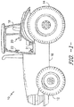
- FIG. 1 illustrates a side view of one embodiment of a work vehicle 10.
- the work vehicle 10 is configured as an agricultural tractor.
- the work vehicle 10 may be configured as any other suitable work vehicle known in the art, such as various other agricultural vehicles, earth-moving vehicles, loaders and/or various other off-road vehicles.
- the work vehicle 10 includes a pair of front wheels 12, a pair or rear wheels 14 and a chassis 16 coupled to and supported by the wheels 12, 14.
- An operator's cab 18 may be supported by a portion of the chassis 16 and may house various control or input devices 20, 21, 22 (e.g., levers, pedals, control panels, buttons and/or the like) for permitting an operator to control the operation of the work vehicle 10.
- the work vehicle 10 may include an input lever 20 for controlling the engine speed of the vehicle 10 and a clutch pedal 21.
- the work vehicle 10 may include a control panel 22 for displaying message windows and/or alerts to the operator and/or for allowing the operator to interface with the vehicle's controller.
- control panel 22 may include buttons, knobs and/or any other suitable input devices that allow the operator to provide user inputs to the controller, such as by allowing the operator to provide an input instructing the controller to operate the work vehicle 10 in an auto-efficiency mode or cruise control mode so as to maintain the vehicle 10 at a desired ground speed.
- the configuration of the work vehicle 10 described above and shown in FIG. 1 is provided only to place the present subject matter in an exemplary field of use.
- the present subject matter may be readily adaptable to any manner of work vehicle configuration.
- the work vehicle may include an articulated chassis to steer the work vehicle 10, or rely on tracks in lieu of the wheels 12, 14.
- the work vehicle 10 may also be configured to be operably coupled to any suitable type of work implement.
- FIG. 2 a schematic diagram of one embodiment of a system 100 for controlling the speed of a work vehicle during downhill operation is illustrated in accordance with aspects of the present subject matter.
- the system 100 will be described herein with reference to the work vehicle 10 shown and described above with reference to FIG. 1 .
- the disclosed system 100 may be utilized to control the operation of any work vehicle having any suitable vehicle configuration.
- the system 100 may generally include a drivetrain 102 suitable for transferring power to the drive wheels of the work vehicle 10 (e.g., the rear wheels 14).
- the drivetrain 102 may include an engine 104 and a transmission 106 configured to be mounted on the chassis 16 ( FIG. 1 ) of the work vehicle 10.
- the transmission 106 may be operably coupled to the engine 104 via one or more shafts 108 and may be configured to provide variably adjusted gear ratios for transferring engine power to the drive wheels 14 via a drive axle assembly 110.
- the drive axle assembly 110 may include a differential 112 coupled to an output shaft 114 of the transmission 106 and one or more axle shafts 116 coupled to the differential 112 for transferring power to the drive wheels 14.
- the system 100 may also include a controller 118 configured to control the operation of one or more components of the work vehicle 10, such as the engine 104 and the transmission 106.
- the controller 118 may be communicatively coupled to one or more components of the engine 104 (e.g., an engine governor or engine control unit (ECU) (not shown)) via one or more communicative links 120 in order to control and/or monitor the speed and/or torque output of the engine 104.
- the controller 118 may be communicatively coupled to one or more transmission components via one or more communicative links 122 to control the operation of the transmission 106.
- the controller 118 may be configured to transmit suitable current commands via communicative link 122 to one or more clutch valves (not shown) to control the engagement and disengagement of one or more clutches (not shown) of the transmission 106.
- the controller 118 may be configured to cause the transmission 106 to be upshifted or downshifted, as desired, to adjust the current gear ratio of the transmission 106.
- the controller 118 may generally comprise any suitable processor-based device known in the art, such as one or more computing devices.
- the controller 118 may include one or more processor(s) 124 and associated memory 126 device(s) configured to perform a variety of computer-implemented functions.
- processor refers not only to integrated circuits referred to in the art as being included in a computer, but also refers to a controller, a microcontroller, a microcomputer, a programmable logic controller (PLC), an application specific integrated circuit, and other programmable circuits.
- PLC programmable logic controller
- the memory 126 of the controller 118 may generally comprise memory element(s) including, but not limited to, computer readable medium (e.g., random access memory (RAM)), computer readable nonvolatile medium (e.g., a flash memory), a floppy disk, a compact disc-read only memory (CD-ROM), a magneto-optical disk (MOD), a digital versatile disc (DVD) and/or other suitable memory elements.
- RAM random access memory
- RAM computer readable nonvolatile medium
- CD-ROM compact disc-read only memory
- MOD magneto-optical disk
- DVD digital versatile disc
- Such memory 126 may generally be configured to store suitable computer-readable instructions that, when implemented by the processor(s) 124, configure the controller 118 to perform various computer-implemented functions, such as the control algorithm 200 described below with reference to FIG. 3 and/or the method 300 described below with reference to FIG. 4 .
- the controller 118 may also include various other suitable components, such as a communications circuit or module, one or more
- controller 118 may correspond to an existing controller of the work vehicle 10 (e.g., an existing engine and/or transmission controller) or the controller 118 may correspond to a separate controller.
- the controller 118 may form all or part of a separate plug-in module that may be installed within the work vehicle 10 to allow for the disclosed system and method to be implemented without requiring additional software to be uploaded onto existing control devices of the vehicle 10.
- the system 100 may also include one or more sensors for monitoring various operating parameters of the work vehicle 10.
- the controller 118 may be communicatively coupled to various sensors, such as a torque sensor 128 and/or a speed sensor 130, mounted on and/or within the engine 104 for monitoring the engine torque loads and/or the engine speed.
- the sensor(s) 128, 130 may comprise an internal sensor(s) of an engine governor (not shown) of the engine 104.
- the system 100 may include any other suitable sensor(s) configured to monitor the torque loads and/or the speed of the engine 104.
- a suitable sensor 132 may be provided in association with the output shaft 108 of the engine 104 for monitoring the current engine speed (e.g., in RPMs).
- the system 100 may also include one or more sensors (e.g., shaft encoders, shaft sensors and/or any other suitable sensors) configured to monitor one or more additional rotational speeds of the drivetrain 102 and/or the ground speed of the work vehicle 10.
- the system 100 may include a first speed sensor 134 provided in operative association with the transmission 106 and/or the output shaft 114 for monitoring the transmission output speed.
- the system 100 may optionally include a second speed sensor 136 provided in operative association with the drive axle assembly 110 for monitoring the axle speed of the drive axles 116 (and, thus, the rotational speed of the drive wheels 14).
- the system 100 may also include a ground speed sensor 138 for monitoring the current ground speed of the work vehicle 10.
- the ground speed sensor 138 may correspond to a GPS device or any other suitable sensing device configured to provide an indication of the ground speed of the work vehicle 10.
- the system 100 may also include one or more input devices 140, 142 communicatively coupled to the controller 118 to allow operator inputs to be provided to the system 100.
- the work vehicle 10 may include an input device 140 (e.g., input lever 20 shown in FIG. 1 ) configured to permit an operator to input an engine speed command corresponding to a desired engine speed for the vehicle 10.
- the controller 118 may be configured to control the operation of the engine 104 in order to achieve the requested engine speed.
- the work vehicle 10 may include a suitable input device 142 (e.g., a button, switch or other suitable input device positioned on the control panel 22 shown in FIG.
- the controller 118 may be configured to control the operation of the engine 104 and/or the transmission 106 in order to achieve the requested ground speed.
- the controller 118 may, in several embodiments, be configured to implement a suitable control algorithm and/or method for controlling the speed of a work vehicle during downhill operation.
- the controller 118 may be configured to automatically downshift the transmission 106 as the work vehicle 10 is traveling downhill to limit over-speeding of the work vehicle 10 when it is determined that one or more downshifting pre-conditions for the vehicle 10 are satisfied.
- the downshifting pre-conditions may be applied by the controller 118 such that the transmission 106 is downshifted only when doing so would avoid unnecessary fuel consumption by the engine 102 and/or limit the engine speed from exceeding a maximum threshold speed set for the engine 102.
- FIG. 3 a flow diagram of one embodiment of a control algorithm 200 that may be used for controlling the speed of a work vehicle during downhill operation is illustrated in accordance with aspects of the present subject matter.
- the control algorithm 200 will be described herein as being implemented by the controller 118 of the system 100 described above with reference to FIG. 2 .
- the various processes described below may alternatively be implemented by a separate computing device or by a combination of computing devices.
- FIG. 3 depicts control steps or functions performed in a particular order for purposes of illustration and discussion, the control algorithms discussed herein are not limited to any particular order or arrangement.
- One skilled in the art, using the disclosures provided herein, will appreciate that various steps or functions of the algorithms disclosed herein can be omitted, rearranged, combined, and/or adapted in various ways without deviating from the scope of the present disclosure.
- the control algorithm 200 may include identifying one or more operating conditions of the work vehicle 10 that are indicative of downhill operation.
- the controller 118 may be configured to monitor any suitable operating parameter(s) of the work vehicle 10 that provides an indication that the work vehicle 10 is currently traveling downhill.
- the controller 118 may be configured to monitor both the engine speed and the engine torque during vehicle operation and analyze such monitored values to identify one or more operating conditions that are indicative of the work vehicle 10 traveling downhill.
- the controller 118 may be configured to use the monitored speed/torque values for the engine 104 to identify whether one or more predetermined downhill-indicating conditions are currently satisfied for the work vehicle 10.
- the control algorithm 200 may, in one embodiment, utilize three separate downhill-indicating conditions (indicated by bracket 204) to estimate when the work vehicle 10 is currently traveling downhill.
- the controller 118 may be configured to determine whether the current engine speed is greater than the requested engine speed for the engine 104. If not, the control algorithm 200 is looped back to its initiating step. However, if the current engine speed is greater than the requested engine speed, the controller 118 may, at (208), determine whether the current engine torque is negative. If not, the control algorithm 200 is looped back to its initiating step. Alternatively, if the current engine torque is negative, the controller 118 may, at (210), determine whether the engine speed is increasing with time.
- the controller 118 may analyze the monitored engine speed values over a given time period to determine whether the engine speed is increasing across such time period. If the engine speed is not increasing with time, the control algorithm 200 is looped back to its initiating step. However, if the controller 118 determines that the engine speed is increasing over time (and, thus, all three downhill-indicating conditions 204 are satisfied), the controller 118 may identify that the work vehicle 10 is currently traveling downhill. As such, the control algorithm 200 may proceed to steps 216, 218 to determine whether a downshift should be performed within the transmission 106 to limit over-speeding of the work vehicle 10 at it is traveling downhill.
- the control algorithm 200 may utilize any other suitable downhill-indicating conditions for estimating or determining when the work vehicle 10 is traveling downhill, including any subcombination of the downhill-indicating conditions 204 shown in FIG. 3 and/or any other suitable downhill-indicating conditions.
- the controller 118 may be communicatively coupled to an orientation or inclination sensor(s) (not shown), such as one or more accelerometers, inclinometers, gyroscopes and/or any other suitable sensor(s) configured to monitor the angle of inclination of the work vehicle 10 by measuring its orientation relative to gravity.
- the controller 118 may be configured to determine when the work vehicle 10 is downwardly inclined based on the sensor measurements in order to identify that the vehicle 10 is traveling downhill.
- the controller 118 may determine if one or more pre-conditions (e.g., as indicated by brackets 214) for downshifting the transmission 106 are satisfied. Specifically, in several embodiments, the controller 118 may only be configured to downshift the transmission 104 during downhill operation when the downshift can be implemented without causing an unnecessary increase in the vehicle's fuel consumption and/or without resulting in the engine speed increasing beyond a given threshold. By requiring such pre-conditions for downshifting the transmission 106, the work vehicle 10 may be operated when traveling downhill in a manner that maintains the desired fuel efficiency while prevents or minimizes potential damage to the engine 106.
- pre-conditions e.g., as indicated by brackets 21
- the controller 118 may, at (216), determine whether the requested axle speed for the work vehicle 10 is less than or equal to an estimated axle speed for the work vehicle 10 assuming the downshift is performed and the engine speed remains constant.
- Such a pre-condition may ensure that the downshift is only performed when the braking action resulting from the downshift would not cause the axle speed to drop below the requested axle speed for the work vehicle 10. Specifically, if the braking action occurring with the downshift would result in a reduction of the axle speed below the requested axle speed for the work vehicle 10, the engine 104 would need to consume additional fuel to increase the axle speed back up to the requested axle speed.
- the operation of the work vehicle 10 may be controlled without causing an unnecessary increase in the vehicle's fuel consumption.
- the control algorithm 200 is looped back to its initiating step without downshifting the transmission 106.
- the controller 118 may then determine whether the second pre-condition for downshifting the transmission 106 is satisfied. For example, at (218), the controller 118 may determine whether the maximum allowable engine speed for the engine 104 is greater than or equal to an estimated engine speed for the engine 104 assuming the downshift is performed.
- the second pre-condition may be provided to ensure that the downshift will not result in the engine speed increasing beyond the maximum allowable engine speed set for the engine 104, thereby preventing or minimizing the potential damage to the engine 104 that may otherwise occur due to an engine overspeed condition.
- the control algorithm 200 is looped back to its initiating step without downshifting the transmission 106.
- the controller 119 determines that the maximum allowable engine speed is greater than or equal to the estimated engine downshift speed (and, thus, both downshifting pre-conditions 214 are satisfied)
- the controller 118 may, at (220), automatically downshift the transmission 106.
- the controller 118 may be configured to automatically control the operation of the transmission 106 such that the transmission 106 is downshifted to a lower gear, thereby preventing or limiting the work vehicle 10 from over-speeding as it travels downhill.
- control algorithm 200 may only utilize one of the downshifting pre-conditions 214 shown in FIG. 3 when determining whether to downshift the transmission 106 as the work vehicle 10 travels downhill.
- any other suitable downshift pre-conditions may be used by the controller 118 for determining whether to downshift the transmission 106.
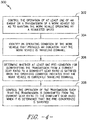
- FIG. 4 a flow diagram of one embodiment of a method 300 for controlling the speed of a work vehicle during downhill operation is illustrated in accordance with aspects of the present subject matter.
- the method 300 will be described herein with reference to the system 100 described above with reference to FIG. 2 and the control algorithm 200 described above with reference to FIG. 3 .
- the disclosed method 300 may be implemented within any other system and/or using any other suitable control algorithm.
- FIG. 4 depicts steps performed in a particular order for purposes of illustration and discussion, the methods discussed herein are not limited to any particular order or arrangement.
- One skilled in the art, using the disclosures provided herein, will appreciate that various steps of the methods disclosed herein can be omitted, rearranged, combined, and/or adapted in various ways without deviating from the scope of the present disclosure.
- the method 300 may include controlling an operation of at least one of an engine or a transmission of a work vehicle so as to maintain the work vehicle operating at a requested speed.
- the system controller 118 may be configured control the operation of the engine 104 and/or transmission 106 so as to maintain one or more requested speeds, such as a requested engine speed, a requested axle speed and/or a requested ground speed.
- the controller 118 may be configured to execute an auto-efficiency mode or cruise control mode in which the operator selects a desired ground speed for the work vehicle 10. The controller may then determine the appropriate engine speed and/or axle speed required to maintain the work vehicle 10 at the operator-selected ground speed.
- the method 300 may include identifying an operating condition of the work vehicle that provides an indication that the work vehicle is traveling downhill.
- the controller 118 may be configured to monitor one or more operating parameters and compare the monitored parameters to one or more predetermined operating conditions for the work vehicle 10 that are indicative of the vehicle 10 currently traveling downhill. For instance, in one embodiment, the controller 118 may determine that the work vehicle 10 is traveling downhill by identifying that the current engine speed is greater than the requested engine speed, that the current engine torque is negative, and that the engine speed is increasing with time.
- any other suitable downhill-indicating conditions may be utilized by the controller 118 to determine or estimate when the work vehicle 10 is travelling downhill.
- the method 300 may include determining whether at least one pre-condition for downshifting the transmission from a current gear ratio to a downshift gear ratio is satisfied when the operating condition indicates that the work vehicle is currently traveling downhill.
- the controller 118 may be configured to evaluate whether first and second pre-conditions are satisfied prior to downshifting the transmission 106, namely whether the requested axle speed for the work vehicle 10 will be less than or equal to an estimated axle speed for the work vehicle 10 following the downshift and whether the maximum allowable engine speed will be greater than or equal to the estimated engine speed for the work vehicle 10 following the downshift.
- any other suitable downshifting pre-condition(s) may be applied by the controller 118, such as by only applying one of the above-mentioned pre-conditions.
- the method 300 may include controlling the operation of the transmission such that the transmission is downshifted from the current gear ratio to the downshift gear ratio when it is determined that the at least one pre-condition is satisfied.
- the controller 118 may be configured to automatically control the operation of the transmission 106.
- the controller 118 may be configured to automatically downshift the transmission 106 to a lower gear to limit over-speeding of the work vehicle 10 as it travels downhill.
- the downshift may be executed so as to maintain the work vehicle 10 operating at the requested axle or wheel speed for the work vehicle (and, thus, the requested ground speed) while minimizing fuel consumption of the engine 104.
Landscapes
- Engineering & Computer Science (AREA)
- Mechanical Engineering (AREA)
- Transportation (AREA)
- Chemical & Material Sciences (AREA)
- Combustion & Propulsion (AREA)
- Automation & Control Theory (AREA)
- General Engineering & Computer Science (AREA)
- Physics & Mathematics (AREA)
- Mathematical Physics (AREA)
- Control Of Transmission Device (AREA)
- Control Of Driving Devices And Active Controlling Of Vehicle (AREA)
Abstract
Description
- The present subject matter relates generally to work vehicles and, more particularly, to a system and method for controlling the speed of a work vehicle during downhill operation so as to limit over-speeding while minimizing fuel consumption.
- When a work vehicle is operating on a downhill slope, the gravity acting on the work vehicle functions to drive the transmission and the engine, particularly when operating on steep slopes or for normal downhill slopes with high vehicle loads. Since conventional engines do not include a mechanism for providing an active-negative torque, there is no active control over the engine speed when gravity begins to drive the engine during downhill operation. As such, in many instances, the only option for regulating the speed of the work vehicle as it travels downhill is to control the operation of the transmission.
- Unfortunately, conventional control systems lack the ability to properly regulate the operation of the transmission while accounting for fuel consumption of the engine so as to maintain a desired fuel efficiency for the work vehicle as it travels downhill. Accordingly, an improved system and method for controlling the speed of a work vehicle during downhill operation would be welcomed in the technology.
- Aspects and advantages of the invention will be set forth in part in the following description, or may be obvious from the description, or may be learned through practice of the invention.
- In one aspect, the present subject matter is directed to a method for controlling the speed of a work vehicle during downhill operation. The method may generally include controlling, with a computing device, an operation of at least one of an engine or a transmission of a work vehicle so as to maintain the work vehicle operating at a requested speed and identifying, with the computing device, an operating condition of the work vehicle that provides an indication that the work vehicle is traveling downhill. In addition, the method may include determining, with the computing device, whether at least one pre-condition for downshifting the transmission from a current gear ratio to a downshift gear ratio is satisfied when the operating condition indicates that the work vehicle is currently traveling downhill, wherein the pre-condition(s) includes a first pre-condition requiring that the requested speed be less than or equal to an estimated speed for the work vehicle following the downshift. Moreover, when it is determined that the pre-condition(s) is satisfied, the method may include controlling, with the computing device, the operation of the transmission such that the transmission is downshifted from the current gear ratio to the downshift gear ratio.
- In another aspect, the present subject matter is directed to a system for controlling the speed of a work vehicle during downhill operation. The system may include an engine, a transmission coupled to the engine, and a controller communicatively coupled to at least one of the engine or the transmission. The controller may include a processor and related memory. The memory may store instructions that, when implemented by the processor, configure the controller to control an operation of at least one of the engine or the transmission so as to maintain the work vehicle operating at a requested speed and identify an operating condition of the work vehicle that provides an indication that the work vehicle is traveling downhill. The controller may also be configured to determine whether at least one pre-condition for downshifting the transmission from a current gear ratio to a downshift gear ratio is satisfied when the operating condition indicates that the work vehicle is currently traveling downhill, wherein the pre-condition(s) includes a first pre-condition requiring that the requested speed be less than or equal to an estimated speed for the work vehicle following the downshift. Moreover, when it is determined that the pre-condition(s) is satisfied, the controller may be configured to control the operation of the transmission such that the transmission is downshifted from the current gear ratio to the downshift gear ratio.
- These and other features, aspects and advantages of the present invention will become better understood with reference to the following description and appended claims. The accompanying drawings, which are incorporated in and constitute a part of this specification, illustrate embodiments of the invention and, together with the description, serve to explain the principles of the invention.
- A full and enabling disclosure of the present invention, including the best mode thereof, directed to one of ordinary skill in the art, is set forth in the specification, which makes reference to the appended figures, in which:
-
FIG. 1 illustrates a side view of one embodiment of a work vehicle in accordance with aspects of the present subject matter; -
FIG. 2 illustrates a schematic view of one embodiment of a system for controlling the speed of a work vehicle during downhill operation in accordance with aspects of the present subject matter; -
FIG. 3 illustrates a flow diagram of one embodiment of a control algorithm configured to be implemented by a controller of a work vehicle for controlling the speed of a work vehicle during downhill operation in accordance with aspects of the present subject matter; and -
FIG. 4 illustrates a flow diagram of one embodiment of a method for controlling the speed of a work vehicle during downhill operation in accordance with aspects of the present subject matter. - Reference now will be made in detail to embodiments of the invention, one or more examples of which are illustrated in the drawings.
- In general, the present subject matter is directed to systems and methods for controlling the speed of a work vehicle during downhill operation. Specifically, in several embodiments, when it is determined that the work vehicle is traveling downhill, a controller of the disclosed system may be configured to automatically downshift the transmission to limit over-speeding of the work vehicle when one or more downshifting pre-conditions are satisfied. For example, in one embodiment, the controller may only be configured to downshift the transmission when a requested axle or wheel speed for the work vehicle is less than or equal to an estimated axle/wheel speed that the work vehicle would achieve following the downshift if the engine speed remained constant. As such, the controller may refrain from downshifting the transmission when the resulting axle/wheel speed would drop below the requested speed, thereby eliminating the need for the engine to burn additional fuel to increase the axle/wheel speed back up to the requested speed. Accordingly, the disclosed system and method may allow for the speed of a work vehicle to be controlled during downhill operation while taking into account fuel consumption considerations.
- It should be appreciated that, in several embodiments of the present subject matter, the disclosed system and method may be implemented when the work vehicle is operating in an auto-efficiency or cruise control mode. For example, the operator may have requested that the work vehicle be maintained at a given ground speed. In such instance, the controller may be configured to control the operation of the vehicle's engine and/or transmission so as to maintain the work vehicle at the requested speed. Thus, when the work vehicle begins to travel downhill, aspects of the present subject matter may be utilized to maintain the work vehicle at or near the requested speed while limiting unnecessary fuel consumption.
- Referring now to the drawings,
FIG. 1 illustrates a side view of one embodiment of awork vehicle 10. As shown, thework vehicle 10 is configured as an agricultural tractor. However, in other embodiments, thework vehicle 10 may be configured as any other suitable work vehicle known in the art, such as various other agricultural vehicles, earth-moving vehicles, loaders and/or various other off-road vehicles. - As shown in
FIG. 1 , thework vehicle 10 includes a pair offront wheels 12, a pair orrear wheels 14 and achassis 16 coupled to and supported by thewheels cab 18 may be supported by a portion of thechassis 16 and may house various control orinput devices work vehicle 10. For instance, as shown inFIG. 1 , thework vehicle 10 may include aninput lever 20 for controlling the engine speed of thevehicle 10 and aclutch pedal 21. In addition, thework vehicle 10 may include acontrol panel 22 for displaying message windows and/or alerts to the operator and/or for allowing the operator to interface with the vehicle's controller. For instance, in one embodiment, thecontrol panel 22 may include buttons, knobs and/or any other suitable input devices that allow the operator to provide user inputs to the controller, such as by allowing the operator to provide an input instructing the controller to operate thework vehicle 10 in an auto-efficiency mode or cruise control mode so as to maintain thevehicle 10 at a desired ground speed. - It should be appreciated that the configuration of the
work vehicle 10 described above and shown inFIG. 1 is provided only to place the present subject matter in an exemplary field of use. Thus, it should be appreciated that the present subject matter may be readily adaptable to any manner of work vehicle configuration. For example, in an alternative embodiment, the work vehicle may include an articulated chassis to steer thework vehicle 10, or rely on tracks in lieu of thewheels work vehicle 10 may also be configured to be operably coupled to any suitable type of work implement. - Referring now to
FIG. 2 , a schematic diagram of one embodiment of asystem 100 for controlling the speed of a work vehicle during downhill operation is illustrated in accordance with aspects of the present subject matter. For purposes of discussion, thesystem 100 will be described herein with reference to thework vehicle 10 shown and described above with reference toFIG. 1 . However, it should be appreciated that, in general, the disclosedsystem 100 may be utilized to control the operation of any work vehicle having any suitable vehicle configuration. - As shown, the
system 100 may generally include adrivetrain 102 suitable for transferring power to the drive wheels of the work vehicle 10 (e.g., the rear wheels 14). In general, thedrivetrain 102 may include anengine 104 and atransmission 106 configured to be mounted on the chassis 16 (FIG. 1 ) of thework vehicle 10. Thetransmission 106 may be operably coupled to theengine 104 via one ormore shafts 108 and may be configured to provide variably adjusted gear ratios for transferring engine power to thedrive wheels 14 via adrive axle assembly 110. As shown, thedrive axle assembly 110 may include adifferential 112 coupled to anoutput shaft 114 of thetransmission 106 and one ormore axle shafts 116 coupled to thedifferential 112 for transferring power to thedrive wheels 14. - As shown in
FIG. 2 , thesystem 100 may also include acontroller 118 configured to control the operation of one or more components of thework vehicle 10, such as theengine 104 and thetransmission 106. For example, thecontroller 118 may be communicatively coupled to one or more components of the engine 104 (e.g., an engine governor or engine control unit (ECU) (not shown)) via one or morecommunicative links 120 in order to control and/or monitor the speed and/or torque output of theengine 104. Similarly, thecontroller 118 may be communicatively coupled to one or more transmission components via one or morecommunicative links 122 to control the operation of thetransmission 106. For instance, thecontroller 118 may be configured to transmit suitable current commands viacommunicative link 122 to one or more clutch valves (not shown) to control the engagement and disengagement of one or more clutches (not shown) of thetransmission 106. As such, thecontroller 118 may be configured to cause thetransmission 106 to be upshifted or downshifted, as desired, to adjust the current gear ratio of thetransmission 106. - It should be appreciated that the
controller 118 may generally comprise any suitable processor-based device known in the art, such as one or more computing devices. Thus, in several embodiments, thecontroller 118 may include one or more processor(s) 124 and associatedmemory 126 device(s) configured to perform a variety of computer-implemented functions. As used herein, the term "processor" refers not only to integrated circuits referred to in the art as being included in a computer, but also refers to a controller, a microcontroller, a microcomputer, a programmable logic controller (PLC), an application specific integrated circuit, and other programmable circuits. Additionally, thememory 126 of thecontroller 118 may generally comprise memory element(s) including, but not limited to, computer readable medium (e.g., random access memory (RAM)), computer readable nonvolatile medium (e.g., a flash memory), a floppy disk, a compact disc-read only memory (CD-ROM), a magneto-optical disk (MOD), a digital versatile disc (DVD) and/or other suitable memory elements.Such memory 126 may generally be configured to store suitable computer-readable instructions that, when implemented by the processor(s) 124, configure thecontroller 118 to perform various computer-implemented functions, such as thecontrol algorithm 200 described below with reference toFIG. 3 and/or themethod 300 described below with reference toFIG. 4 . In addition, thecontroller 118 may also include various other suitable components, such as a communications circuit or module, one or more input/output channels, a data/control bus and/or the like. - It should also be appreciated that the
controller 118 may correspond to an existing controller of the work vehicle 10 (e.g., an existing engine and/or transmission controller) or thecontroller 118 may correspond to a separate controller. For instance, in one embodiment, thecontroller 118 may form all or part of a separate plug-in module that may be installed within thework vehicle 10 to allow for the disclosed system and method to be implemented without requiring additional software to be uploaded onto existing control devices of thevehicle 10. - The
system 100 may also include one or more sensors for monitoring various operating parameters of thework vehicle 10. For example, as shown inFIG. 2 , thecontroller 118 may be communicatively coupled to various sensors, such as atorque sensor 128 and/or aspeed sensor 130, mounted on and/or within theengine 104 for monitoring the engine torque loads and/or the engine speed. In one embodiment, the sensor(s) 128, 130 may comprise an internal sensor(s) of an engine governor (not shown) of theengine 104. In another embodiment, thesystem 100 may include any other suitable sensor(s) configured to monitor the torque loads and/or the speed of theengine 104. For instance, asuitable sensor 132 may be provided in association with theoutput shaft 108 of theengine 104 for monitoring the current engine speed (e.g., in RPMs). - Moreover, the
system 100 may also include one or more sensors (e.g., shaft encoders, shaft sensors and/or any other suitable sensors) configured to monitor one or more additional rotational speeds of thedrivetrain 102 and/or the ground speed of thework vehicle 10. For example, as shown inFIG. 2 , thesystem 100 may include afirst speed sensor 134 provided in operative association with thetransmission 106 and/or theoutput shaft 114 for monitoring the transmission output speed. In addition, thesystem 100 may optionally include asecond speed sensor 136 provided in operative association with thedrive axle assembly 110 for monitoring the axle speed of the drive axles 116 (and, thus, the rotational speed of the drive wheels 14). Further, thesystem 100 may also include aground speed sensor 138 for monitoring the current ground speed of thework vehicle 10. In one embodiment, theground speed sensor 138 may correspond to a GPS device or any other suitable sensing device configured to provide an indication of the ground speed of thework vehicle 10. - As shown in
FIG. 2 , thesystem 100 may also include one ormore input devices controller 118 to allow operator inputs to be provided to thesystem 100. For example, as indicated above, thework vehicle 10 may include an input device 140 (e.g.,input lever 20 shown inFIG. 1 ) configured to permit an operator to input an engine speed command corresponding to a desired engine speed for thevehicle 10. Upon receipt of the engine speed command, thecontroller 118 may be configured to control the operation of theengine 104 in order to achieve the requested engine speed. Similarly, as indicated above, thework vehicle 10 may include a suitable input device 142 (e.g., a button, switch or other suitable input device positioned on thecontrol panel 22 shown inFIG. 1 ) configured to permit an operator to input a ground speed command corresponding to a desired ground speed for thevehicle 10, such as when thework vehicle 10 is being operated in an auto-efficiency mode or cruise control mode. In such an embodiment, upon receipt of the ground speed command, thecontroller 118 may be configured to control the operation of theengine 104 and/or thetransmission 106 in order to achieve the requested ground speed. - Moreover, in accordance with aspects of the present subject matter, the
controller 118 may, in several embodiments, be configured to implement a suitable control algorithm and/or method for controlling the speed of a work vehicle during downhill operation. For example, as will be described below with reference toFIGS. 3 and4 , thecontroller 118 may be configured to automatically downshift thetransmission 106 as thework vehicle 10 is traveling downhill to limit over-speeding of thework vehicle 10 when it is determined that one or more downshifting pre-conditions for thevehicle 10 are satisfied. For example, the downshifting pre-conditions may be applied by thecontroller 118 such that thetransmission 106 is downshifted only when doing so would avoid unnecessary fuel consumption by theengine 102 and/or limit the engine speed from exceeding a maximum threshold speed set for theengine 102. - Referring now to
FIG. 3 , a flow diagram of one embodiment of acontrol algorithm 200 that may be used for controlling the speed of a work vehicle during downhill operation is illustrated in accordance with aspects of the present subject matter. In general, thecontrol algorithm 200 will be described herein as being implemented by thecontroller 118 of thesystem 100 described above with reference toFIG. 2 . However, it should be appreciated that the various processes described below may alternatively be implemented by a separate computing device or by a combination of computing devices. In addition, althoughFIG. 3 depicts control steps or functions performed in a particular order for purposes of illustration and discussion, the control algorithms discussed herein are not limited to any particular order or arrangement. One skilled in the art, using the disclosures provided herein, will appreciate that various steps or functions of the algorithms disclosed herein can be omitted, rearranged, combined, and/or adapted in various ways without deviating from the scope of the present disclosure. - In several embodiments, the
control algorithm 200 may include identifying one or more operating conditions of thework vehicle 10 that are indicative of downhill operation. In general, thecontroller 118 may be configured to monitor any suitable operating parameter(s) of thework vehicle 10 that provides an indication that thework vehicle 10 is currently traveling downhill. For instance, in one embodiment, thecontroller 118 may be configured to monitor both the engine speed and the engine torque during vehicle operation and analyze such monitored values to identify one or more operating conditions that are indicative of thework vehicle 10 traveling downhill. Specifically, as will be described below, thecontroller 118 may be configured to use the monitored speed/torque values for theengine 104 to identify whether one or more predetermined downhill-indicating conditions are currently satisfied for thework vehicle 10. - For example, as shown in
FIG. 3 , thecontrol algorithm 200 may, in one embodiment, utilize three separate downhill-indicating conditions (indicated by bracket 204) to estimate when thework vehicle 10 is currently traveling downhill. Specifically, at (206), thecontroller 118 may be configured to determine whether the current engine speed is greater than the requested engine speed for theengine 104. If not, thecontrol algorithm 200 is looped back to its initiating step. However, if the current engine speed is greater than the requested engine speed, thecontroller 118 may, at (208), determine whether the current engine torque is negative. If not, thecontrol algorithm 200 is looped back to its initiating step. Alternatively, if the current engine torque is negative, thecontroller 118 may, at (210), determine whether the engine speed is increasing with time. For example, thecontroller 118 may analyze the monitored engine speed values over a given time period to determine whether the engine speed is increasing across such time period. If the engine speed is not increasing with time, thecontrol algorithm 200 is looped back to its initiating step. However, if thecontroller 118 determines that the engine speed is increasing over time (and, thus, all three downhill-indicatingconditions 204 are satisfied), thecontroller 118 may identify that thework vehicle 10 is currently traveling downhill. As such, thecontrol algorithm 200 may proceed tosteps transmission 106 to limit over-speeding of thework vehicle 10 at it is traveling downhill. - It should be appreciated that, in other embodiments, the
control algorithm 200 may utilize any other suitable downhill-indicating conditions for estimating or determining when thework vehicle 10 is traveling downhill, including any subcombination of the downhill-indicatingconditions 204 shown inFIG. 3 and/or any other suitable downhill-indicating conditions. For instance, in an alternative embodiment, thecontroller 118 may be communicatively coupled to an orientation or inclination sensor(s) (not shown), such as one or more accelerometers, inclinometers, gyroscopes and/or any other suitable sensor(s) configured to monitor the angle of inclination of thework vehicle 10 by measuring its orientation relative to gravity. In such an embodiment, thecontroller 118 may be configured to determine when thework vehicle 10 is downwardly inclined based on the sensor measurements in order to identify that thevehicle 10 is traveling downhill. - As shown in
FIG. 3 , upon determining that thework vehicle 10 is traveling downhill, thecontroller 118 may determine if one or more pre-conditions (e.g., as indicated by brackets 214) for downshifting thetransmission 106 are satisfied. Specifically, in several embodiments, thecontroller 118 may only be configured to downshift thetransmission 104 during downhill operation when the downshift can be implemented without causing an unnecessary increase in the vehicle's fuel consumption and/or without resulting in the engine speed increasing beyond a given threshold. By requiring such pre-conditions for downshifting thetransmission 106, thework vehicle 10 may be operated when traveling downhill in a manner that maintains the desired fuel efficiency while prevents or minimizes potential damage to theengine 106. - As shown in
FIG. 3 , as a first pre-condition for downshifting thetransmission 106, thecontroller 118 may, at (216), determine whether the requested axle speed for thework vehicle 10 is less than or equal to an estimated axle speed for thework vehicle 10 assuming the downshift is performed and the engine speed remains constant. Such a pre-condition may ensure that the downshift is only performed when the braking action resulting from the downshift would not cause the axle speed to drop below the requested axle speed for thework vehicle 10. Specifically, if the braking action occurring with the downshift would result in a reduction of the axle speed below the requested axle speed for thework vehicle 10, theengine 104 would need to consume additional fuel to increase the axle speed back up to the requested axle speed. Thus, by implementing the first pre-condition for downshifting thetransmission 106, the operation of thework vehicle 10 may be controlled without causing an unnecessary increase in the vehicle's fuel consumption. - It should be appreciated that, in one embodiment, the first pre-condition for downshifting the
transmission 106 may be expressed according to the following relationship (i.e., Equation 1):
work vehicle 10 to maintain the desired ground speed, ωdownshift_Axle corresponds to the estimated axle speed for thework vehicle 10 following the downshift, ωeng corresponds to the current engine speed for theengine 106, and ηdownshift corresponds to the gear ratio for thetransmission 106 following the downshift. - As shown in
FIG. 3 , if the requested axle speed will be greater than the estimated axle speed for thework vehicle 10 following the downshift, thecontrol algorithm 200 is looped back to its initiating step without downshifting thetransmission 106. However, if the requested axle speed will be less than or equal to the estimated axle speed for the work vehicle following the downshift, thecontroller 118 may then determine whether the second pre-condition for downshifting thetransmission 106 is satisfied. For example, at (218), thecontroller 118 may determine whether the maximum allowable engine speed for theengine 104 is greater than or equal to an estimated engine speed for theengine 104 assuming the downshift is performed. Specifically, given that downshifting thetransmission 106 will drive the engine speed upward, the second pre-condition may be provided to ensure that the downshift will not result in the engine speed increasing beyond the maximum allowable engine speed set for theengine 104, thereby preventing or minimizing the potential damage to theengine 104 that may otherwise occur due to an engine overspeed condition. - It should be appreciated that, in one embodiment, the second pre-condition for downshifting the
transmission 106 may be expressed according to the following relationship (i.e., Equation 2):
engine 104, ωdownshift_eng corresponds to the estimated engine speed following the downshift if the axle speed remains constant, ωeng corresponds to the current engine speed for theengine 104, ηcurrent corresponds to the current gear ratio for thetransmission 106, and ηdownshift corresponds to the gear ratio for thetransmission 106 following the downshift. - As shown in
FIG. 3 , if the maximum allowable engine speed for theengine 104 is not greater than or equal to the estimated engine downshift speed, thecontrol algorithm 200 is looped back to its initiating step without downshifting thetransmission 106. However, if the controller 119 determines that the maximum allowable engine speed is greater than or equal to the estimated engine downshift speed (and, thus, both downshiftingpre-conditions 214 are satisfied), thecontroller 118 may, at (220), automatically downshift thetransmission 106. Specifically, thecontroller 118 may be configured to automatically control the operation of thetransmission 106 such that thetransmission 106 is downshifted to a lower gear, thereby preventing or limiting thework vehicle 10 from over-speeding as it travels downhill. - It should be appreciated that, in other embodiments, the
control algorithm 200 may only utilize one of the downshifting pre-conditions 214 shown inFIG. 3 when determining whether to downshift thetransmission 106 as thework vehicle 10 travels downhill. Alternatively, any other suitable downshift pre-conditions may be used by thecontroller 118 for determining whether to downshift thetransmission 106. - Referring now to
FIG. 4 , a flow diagram of one embodiment of amethod 300 for controlling the speed of a work vehicle during downhill operation is illustrated in accordance with aspects of the present subject matter. In general, themethod 300 will be described herein with reference to thesystem 100 described above with reference toFIG. 2 and thecontrol algorithm 200 described above with reference toFIG. 3 . However, it should be appreciated by those of ordinary skill in the art that the disclosedmethod 300 may be implemented within any other system and/or using any other suitable control algorithm. In addition, althoughFIG. 4 depicts steps performed in a particular order for purposes of illustration and discussion, the methods discussed herein are not limited to any particular order or arrangement. One skilled in the art, using the disclosures provided herein, will appreciate that various steps of the methods disclosed herein can be omitted, rearranged, combined, and/or adapted in various ways without deviating from the scope of the present disclosure. - As shown in
FIG. 4 , at (302), themethod 300 may include controlling an operation of at least one of an engine or a transmission of a work vehicle so as to maintain the work vehicle operating at a requested speed. As indicated above, thesystem controller 118 may be configured control the operation of theengine 104 and/ortransmission 106 so as to maintain one or more requested speeds, such as a requested engine speed, a requested axle speed and/or a requested ground speed. For instance, in one embodiment, thecontroller 118 may be configured to execute an auto-efficiency mode or cruise control mode in which the operator selects a desired ground speed for thework vehicle 10. The controller may then determine the appropriate engine speed and/or axle speed required to maintain thework vehicle 10 at the operator-selected ground speed. - Additionally, at (304), the
method 300 may include identifying an operating condition of the work vehicle that provides an indication that the work vehicle is traveling downhill. Specifically, as indicated above, thecontroller 118 may be configured to monitor one or more operating parameters and compare the monitored parameters to one or more predetermined operating conditions for thework vehicle 10 that are indicative of thevehicle 10 currently traveling downhill. For instance, in one embodiment, thecontroller 118 may determine that thework vehicle 10 is traveling downhill by identifying that the current engine speed is greater than the requested engine speed, that the current engine torque is negative, and that the engine speed is increasing with time. However, in other embodiments, any other suitable downhill-indicating conditions may be utilized by thecontroller 118 to determine or estimate when thework vehicle 10 is travelling downhill. - Moreover, at (306), the
method 300 may include determining whether at least one pre-condition for downshifting the transmission from a current gear ratio to a downshift gear ratio is satisfied when the operating condition indicates that the work vehicle is currently traveling downhill. For instance, as indicated above, thecontroller 118 may be configured to evaluate whether first and second pre-conditions are satisfied prior to downshifting thetransmission 106, namely whether the requested axle speed for thework vehicle 10 will be less than or equal to an estimated axle speed for thework vehicle 10 following the downshift and whether the maximum allowable engine speed will be greater than or equal to the estimated engine speed for thework vehicle 10 following the downshift. However, in other embodiments, any other suitable downshifting pre-condition(s) may be applied by thecontroller 118, such as by only applying one of the above-mentioned pre-conditions. - Referring still to
FIG. 4 , at (308), themethod 300 may include controlling the operation of the transmission such that the transmission is downshifted from the current gear ratio to the downshift gear ratio when it is determined that the at least one pre-condition is satisfied. For example, as indicated above, thecontroller 118 may be configured to automatically control the operation of thetransmission 106. Thus, when it is determined that the downshifting pre-condition(s) is/are satisfied, thecontroller 118 may be configured to automatically downshift thetransmission 106 to a lower gear to limit over-speeding of thework vehicle 10 as it travels downhill. In particular, the downshift may be executed so as to maintain thework vehicle 10 operating at the requested axle or wheel speed for the work vehicle (and, thus, the requested ground speed) while minimizing fuel consumption of theengine 104.
Claims (15)
- A method for controlling the speed of a work vehicle (10) during downhill operation, the method comprising:controlling, with a computing device, an operation of at least one of an engine (104) or a transmission (106) of a work vehicle (10) so as to maintain the work vehicle operating at a requested speed;identifying, with the computing device, an operating condition of the work vehicle (10) that provides an indication that the work vehicle (10) is traveling downhill;determining, with the computing device, whether at least one pre-condition for downshifting the transmission (106) from a current gear ratio to a downshift gear ratio is satisfied when the operating condition indicates that the work vehicle (10) is currently traveling downhill, the at least one pre-condition including a first pre-condition requiring that the requested speed be less than or equal to an estimated speed for the work vehicle (10) following the downshift;when it is determined that the at least one pre-condition is satisfied, controlling, with the computing device, the operation of the transmission (106) such that the transmission (106) is downshifted from the current gear ratio to the downshift gear ratio.
- The method of claim 1, wherein the requested speed corresponds to a requested axle speed for the work vehicle (10).
- The method of claim 2, wherein determining whether the first pre-condition is satisfied comprises determining whether the following relationship is satisfied:

- The method of claim 1, wherein the at least one pre-condition further comprises a second pre-condition requiring that a maximum allowable engine speed for the engine (104) be greater than or equal to an estimated engine speed for the engine (104) following the downshift.
- The method of claim 4, wherein determining whether the second pre-condition is satisfied comprises determining whether the following relationship is satisfied:

- The method of claim 1, further comprising monitoring a current engine speed of the engine (104) relative to a requested engine speed for the engine (104).
- The method of claim 6, wherein identifying the operating condition of the work vehicle (10) comprises identifying that the engine speed is greater than the requested engine speed.
- The method of claim 7, wherein identifying the operating condition of the work vehicle (10) further comprises identifying that an engine torque for the engine (104) is negative and that the engine speed is increasing over time.
- A system for controlling the speed of a work vehicle (10) during downhill operation, the system comprising:an engine (104);a transmission (106) coupled to the engine (104);a controller (118) communicatively coupled to at least one of the engine (104) or the transmission (106), the controller (118) including a processor (124) and related memory (126), the memory (126) storing instructions that, when implemented by the processor (124), configure the controller (118) to:control an operation of at least one of the engine (104) or the transmission (106) so as to maintain the work vehicle (10) operating at a requested speed;identify an operating condition of the work vehicle (10) that provides an indication that the work vehicle (10) is traveling downhill;determine whether at least one pre-condition for downshifting the transmission (106) from a current gear ratio to a downshift gear ratio is satisfied when the operating condition indicates that the work vehicle (10) is currently traveling downhill, the at least one pre-condition including a first pre-condition requiring that the requested speed be less than or equal to an estimated speed for the work vehicle (10) following the downshift; andwhen it is determined that the at least one pre-condition is satisfied, control the operation of the transmission such that the transmission is downshifted from the current gear ratio to the downshift gear ratio.
- The system of claim 9, wherein the requested speed corresponds to a requested axle speed for the work vehicle (10).
- The system of claim 10, wherein the controller (118) is configured to determine whether the first pre-condition is satisfied by determining whether the following relationship is satisfied:

- The system of claim 9, wherein the at least one pre-condition further comprises a second pre-condition requiring that a maximum allowable engine speed for the engine (104) be greater than or equal to an estimated engine speed for the engine (104) following the downshift.
- The system of claim 12, wherein the controller (118) is configured to determine whether the second pre-condition is satisfied by determining whether the following relationship is satisfied:

- The system of claim 9, wherein the controller (118) is further configured to monitor a current engine speed of the engine (104) relative to a requested engine speed for the engine (104).
- The system of claim 14, wherein the controller (118) is configured to identify the operating condition of the work vehicle (10) by identifying that the engine speed is greater than the requested engine speed.
Applications Claiming Priority (1)
| Application Number | Priority Date | Filing Date | Title |
|---|---|---|---|
| US15/620,970 US10336311B2 (en) | 2017-06-13 | 2017-06-13 | System and method for controlling the speed of a work vehicle during downhill operation |
Publications (1)
| Publication Number | Publication Date |
|---|---|
| EP3415391A1 true EP3415391A1 (en) | 2018-12-19 |
Family
ID=62748704
Family Applications (1)
| Application Number | Title | Priority Date | Filing Date |
|---|---|---|---|
| EP18177158.5A Withdrawn EP3415391A1 (en) | 2017-06-13 | 2018-06-12 | System and method for controlling the speed of a work vehicle during downhill operation |
Country Status (4)
| Country | Link |
|---|---|
| US (1) | US10336311B2 (en) |
| EP (1) | EP3415391A1 (en) |
| CN (1) | CN109084014B (en) |
| BR (1) | BR102018010643A2 (en) |
Families Citing this family (3)
| Publication number | Priority date | Publication date | Assignee | Title |
|---|---|---|---|---|
| US10781916B2 (en) * | 2018-11-06 | 2020-09-22 | Toyota Motor Engineering & Manufacturing North America, Inc. | System and method for controlling engine braking |
| DE102021212421A1 (en) * | 2021-11-04 | 2023-05-04 | Zf Friedrichshafen Ag | Traction drive system and method of operating a traction drive system |
| CN117072626A (en) * | 2022-05-09 | 2023-11-17 | 北汽福田汽车股份有限公司 | Rear axle speed regulator, drive system and control method of rear axle speed regulator |
Citations (4)
| Publication number | Priority date | Publication date | Assignee | Title |
|---|---|---|---|---|
| US20010016795A1 (en) * | 1998-11-13 | 2001-08-23 | Cummins Engine Company, Inc. | System and method for controlling vehicle braking operation |
| US20020115531A1 (en) * | 2000-12-20 | 2002-08-22 | Degroot Jeffrey L. | Overspeed prevention |
| US20130066493A1 (en) * | 2011-09-13 | 2013-03-14 | Ford Global Technologies, Llc | Method and system for vehicle speed control |
| US20160264122A1 (en) * | 2015-03-10 | 2016-09-15 | Toyota Motor Engineering & Manufacturing North America, Inc. | Grade logic braking system |
Family Cites Families (32)
| Publication number | Priority date | Publication date | Assignee | Title |
|---|---|---|---|---|
| US3599504A (en) | 1970-02-02 | 1971-08-17 | Borg Warner | Automatic transmission |
| US4594666A (en) | 1983-07-11 | 1986-06-10 | J. I. Case Company | Transmission monitor/control microprocessor for continuously variable power train |
| US5113721A (en) | 1987-10-12 | 1992-05-19 | Auto Polly Gesellschaft M.B.H. | Method and apparatus for controlling a motor vehicle drive train |
| US5287773A (en) | 1992-01-31 | 1994-02-22 | Toyota Jidosha Kabushiki Kaisha | Apparatus for controlling engine brake force during vehicle running on downhill with released accelerator |
| JP3334948B2 (en) * | 1993-06-11 | 2002-10-15 | 三菱自動車工業株式会社 | Automatic transmission for vehicles |
| JP2959938B2 (en) * | 1993-08-31 | 1999-10-06 | 本田技研工業株式会社 | Control device for automatic transmission for vehicles |
| US5470288A (en) | 1993-10-06 | 1995-11-28 | Ford Motor Company | Engine torque compensation shift scheduling of an automatic transmission for motor vehicles |
| JP3284852B2 (en) * | 1995-10-20 | 2002-05-20 | 日産自動車株式会社 | Transmission control device for continuously variable transmission |
| US5765117A (en) * | 1995-11-07 | 1998-06-09 | Unisia Jecs Corporation | Method and apparatus for controlling the speed change of a vehicle automatic transmission |
| JP3747959B2 (en) * | 1996-04-11 | 2006-02-22 | 株式会社日立製作所 | Downhill traveling control device for vehicle |
| JP3783277B2 (en) * | 1996-04-25 | 2006-06-07 | トヨタ自動車株式会社 | Slip control device for vehicle lock-up clutch |
| KR19980087004A (en) * | 1997-05-14 | 1998-12-05 | 가나이 쯔도무 | Automatic transmission control device and control method of car |
| US6067495A (en) * | 1997-06-24 | 2000-05-23 | Chrysler Corporation | Acceleration based shift strategy for an automatic transmission |
| US6349253B1 (en) * | 1998-11-13 | 2002-02-19 | Cummins Engine, Inc. | System and method for controlling downhill vehicle operation |
| EP1172248A3 (en) | 2000-07-12 | 2006-10-04 | Deere & Company | Work vehicle with operator selected load control |
| GB2395989B (en) * | 2002-11-27 | 2007-02-07 | Komatsu Uk Ltd | Travel control apparatus of hydraulic travelling vehicle |
| JP4446769B2 (en) | 2004-03-12 | 2010-04-07 | 株式会社ホンダロック | Outdoor handle device for vehicle door |
| JP4232825B2 (en) * | 2007-01-12 | 2009-03-04 | トヨタ自動車株式会社 | Vehicle control device |
| US8370032B2 (en) * | 2007-07-12 | 2013-02-05 | Toyota Motor Engineering & Manufacturing North America, Inc. | Systems and methods for shift control for vehicular transmission |
| JP4931999B2 (en) * | 2007-07-18 | 2012-05-16 | 株式会社小松製作所 | Work vehicle, vehicle speed control method for work vehicle, and vehicle speed control device for work vehicle |
| DE102007044434A1 (en) | 2007-09-18 | 2009-03-19 | Zf Friedrichshafen Ag | Method for controlling an automated stepped gearbox |
| US8121763B2 (en) | 2008-12-08 | 2012-02-21 | Cnh America Llc | Automatic productivity management control with standard power shift transmission |
| BRPI0925298B1 (en) * | 2009-07-02 | 2021-03-30 | Volvo Lastvagnar Ab | METHOD AND SYSTEM FOR CONTROL OF A VEHICLE CRUISE CONTROL |
| US8401753B2 (en) * | 2009-11-23 | 2013-03-19 | Caterpillar Inc. | Automatic downhill speed control system |
| DE102010006643A1 (en) * | 2010-02-03 | 2011-08-04 | GM Global Technology Operations LLC, ( n. d. Ges. d. Staates Delaware ), Mich. | Method for controlling an automatic transmission of a motor vehicle, control device for an automatic transmission of a motor vehicle and motor vehicle |
| DE102010061823B4 (en) | 2010-11-24 | 2020-02-13 | Zf Friedrichshafen Ag | Method of operating a powertrain |
| SE538649C2 (en) * | 2012-06-27 | 2016-10-11 | Scania Cv Ab | Method and system for selecting a transmission mode in a vehicle |
| US9052013B2 (en) * | 2012-12-14 | 2015-06-09 | Caterpillar Inc. | Grade and payload based transmission gear selection strategy |
| CA2860687C (en) * | 2013-07-12 | 2015-07-21 | Shinya Kondou | Work vehicle and method of controlling the same |
| US9835248B2 (en) | 2014-05-28 | 2017-12-05 | Cummins Inc. | Systems and methods for dynamic gear state and vehicle speed management |
| US9643610B2 (en) * | 2015-04-10 | 2017-05-09 | Volvo Truck Corporation | Method and arrangement for controlling an automatic transmission unit |
| US10065641B2 (en) * | 2016-04-15 | 2018-09-04 | Ford Global Technologies, Llc | Brake fade and brake capacity based powertrain operation |
-
2017
- 2017-06-13 US US15/620,970 patent/US10336311B2/en active Active
-
2018
- 2018-05-24 BR BR102018010643-0A patent/BR102018010643A2/en not_active Application Discontinuation
- 2018-06-12 EP EP18177158.5A patent/EP3415391A1/en not_active Withdrawn
- 2018-06-13 CN CN201810604139.5A patent/CN109084014B/en not_active Expired - Fee Related
Patent Citations (4)
| Publication number | Priority date | Publication date | Assignee | Title |
|---|---|---|---|---|
| US20010016795A1 (en) * | 1998-11-13 | 2001-08-23 | Cummins Engine Company, Inc. | System and method for controlling vehicle braking operation |
| US20020115531A1 (en) * | 2000-12-20 | 2002-08-22 | Degroot Jeffrey L. | Overspeed prevention |
| US20130066493A1 (en) * | 2011-09-13 | 2013-03-14 | Ford Global Technologies, Llc | Method and system for vehicle speed control |
| US20160264122A1 (en) * | 2015-03-10 | 2016-09-15 | Toyota Motor Engineering & Manufacturing North America, Inc. | Grade logic braking system |
Also Published As
| Publication number | Publication date |
|---|---|
| CN109084014A (en) | 2018-12-25 |
| US20180354488A1 (en) | 2018-12-13 |
| US10336311B2 (en) | 2019-07-02 |
| CN109084014B (en) | 2021-09-07 |
| BR102018010643A2 (en) | 2019-01-15 |
Similar Documents
| Publication | Publication Date | Title |
|---|---|---|
| EP2892772B1 (en) | Vehicle control system and method | |
| EP2892779B1 (en) | Vehicle control system and method | |
| US9014931B2 (en) | System and method for controlling a transmission | |
| US10328942B2 (en) | Motor vehicle controller and method | |
| US9052013B2 (en) | Grade and payload based transmission gear selection strategy | |
| EP3153371B1 (en) | System and method for automatically controlling vehicle speed based on track-related temperatures of a work vehicle | |
| CN113464638B (en) | Manual mode gear shifting control method and vehicle | |
| US9868439B2 (en) | Vehicle control system | |
| US8095286B2 (en) | Method for controlling shifts in an automated gearshift transmission | |
| US8849528B2 (en) | System and method for controlling a transmission | |
| CN108544984A (en) | A kind of integral new-energy passenger wriggling control method and system | |
| JP2012532057A (en) | Method and system for controlling vehicle cruise control | |
| US10060486B2 (en) | System and method for controlling the engagement of a PTO clutch for a work vehicle | |
| US8781695B2 (en) | Method and apparatus for controlling pickup on uphill for a motor-vehicle provided with an automatic or robotized gearbox | |
| US10465757B2 (en) | System and method for adaptive engagement control of a PTO clutch of a work vehicle | |
| EP2886411B1 (en) | System and method for enhancing the performance of a work vehicle | |
| US10336311B2 (en) | System and method for controlling the speed of a work vehicle during downhill operation | |
| CN116279396A (en) | Hybrid vehicle control method, device, storage medium and vehicle | |
| US20150239469A1 (en) | Vehicle control system | |
| CN118004136A (en) | Vehicle mode switching control method, device, vehicle and medium | |
| CN101842259A (en) | A method for a more efficient use of a combustion engine in a vehicle | |
| US10759443B2 (en) | System and method for detecting parastic power circulation within a work vehicle | |
| US10823287B2 (en) | System and method for determining and controlling engine speeds during gear shifting | |
| KR102142632B1 (en) | System and method for controlling engine idle speed of a manual transmission vehicle | |
| EP4678490A1 (en) | Predictive dynamic speed control for a vehicle traveling along a hilled route |
Legal Events
| Date | Code | Title | Description |
|---|---|---|---|
| PUAI | Public reference made under article 153(3) epc to a published international application that has entered the european phase |
Free format text: ORIGINAL CODE: 0009012 |
|
| STAA | Information on the status of an ep patent application or granted ep patent |
Free format text: STATUS: THE APPLICATION HAS BEEN PUBLISHED |
|
| AK | Designated contracting states |
Kind code of ref document: A1 Designated state(s): AL AT BE BG CH CY CZ DE DK EE ES FI FR GB GR HR HU IE IS IT LI LT LU LV MC MK MT NL NO PL PT RO RS SE SI SK SM TR |
|
| AX | Request for extension of the european patent |
Extension state: BA ME |
|
| STAA | Information on the status of an ep patent application or granted ep patent |
Free format text: STATUS: REQUEST FOR EXAMINATION WAS MADE |
|
| 17P | Request for examination filed |
Effective date: 20190619 |
|
| RBV | Designated contracting states (corrected) |
Designated state(s): AL AT BE BG CH CY CZ DE DK EE ES FI FR GB GR HR HU IE IS IT LI LT LU LV MC MK MT NL NO PL PT RO RS SE SI SK SM TR |
|
| STAA | Information on the status of an ep patent application or granted ep patent |
Free format text: STATUS: EXAMINATION IS IN PROGRESS |
|
| 17Q | First examination report despatched |
Effective date: 20220630 |
|
| STAA | Information on the status of an ep patent application or granted ep patent |
Free format text: STATUS: THE APPLICATION IS DEEMED TO BE WITHDRAWN |
|
| 18D | Application deemed to be withdrawn |
Effective date: 20221111 |