EP3415384A1 - Slow speed automated vehicle brake pressure control system - Google Patents
Slow speed automated vehicle brake pressure control system Download PDFInfo
- Publication number
- EP3415384A1 EP3415384A1 EP18177228.6A EP18177228A EP3415384A1 EP 3415384 A1 EP3415384 A1 EP 3415384A1 EP 18177228 A EP18177228 A EP 18177228A EP 3415384 A1 EP3415384 A1 EP 3415384A1
- Authority
- EP
- European Patent Office
- Prior art keywords
- vehicle
- speed
- host
- motion
- stationary
- Prior art date
- Legal status (The legal status is an assumption and is not a legal conclusion. Google has not performed a legal analysis and makes no representation as to the accuracy of the status listed.)
- Withdrawn
Links
Images

Classifications
-
- B—PERFORMING OPERATIONS; TRANSPORTING
- B60—VEHICLES IN GENERAL
- B60T—VEHICLE BRAKE CONTROL SYSTEMS OR PARTS THEREOF; BRAKE CONTROL SYSTEMS OR PARTS THEREOF, IN GENERAL; ARRANGEMENT OF BRAKING ELEMENTS ON VEHICLES IN GENERAL; PORTABLE DEVICES FOR PREVENTING UNWANTED MOVEMENT OF VEHICLES; VEHICLE MODIFICATIONS TO FACILITATE COOLING OF BRAKES
- B60T8/00—Arrangements for adjusting wheel-braking force to meet varying vehicular or ground-surface conditions, e.g. limiting or varying distribution of braking force
- B60T8/32—Arrangements for adjusting wheel-braking force to meet varying vehicular or ground-surface conditions, e.g. limiting or varying distribution of braking force responsive to a speed condition, e.g. acceleration or deceleration
-
- B—PERFORMING OPERATIONS; TRANSPORTING
- B60—VEHICLES IN GENERAL
- B60T—VEHICLE BRAKE CONTROL SYSTEMS OR PARTS THEREOF; BRAKE CONTROL SYSTEMS OR PARTS THEREOF, IN GENERAL; ARRANGEMENT OF BRAKING ELEMENTS ON VEHICLES IN GENERAL; PORTABLE DEVICES FOR PREVENTING UNWANTED MOVEMENT OF VEHICLES; VEHICLE MODIFICATIONS TO FACILITATE COOLING OF BRAKES
- B60T8/00—Arrangements for adjusting wheel-braking force to meet varying vehicular or ground-surface conditions, e.g. limiting or varying distribution of braking force
- B60T8/17—Using electrical or electronic regulation means to control braking
- B60T8/172—Determining control parameters used in the regulation, e.g. by calculations involving measured or detected parameters
-
- B—PERFORMING OPERATIONS; TRANSPORTING
- B60—VEHICLES IN GENERAL
- B60W—CONJOINT CONTROL OF VEHICLE SUB-UNITS OF DIFFERENT TYPE OR DIFFERENT FUNCTION; CONTROL SYSTEMS SPECIALLY ADAPTED FOR HYBRID VEHICLES; ROAD VEHICLE DRIVE CONTROL SYSTEMS FOR PURPOSES NOT RELATED TO THE CONTROL OF A PARTICULAR SUB-UNIT
- B60W30/00—Purposes of road vehicle drive control systems not related to the control of a particular sub-unit, e.g. of systems using conjoint control of vehicle sub-units, or advanced driver assistance systems for ensuring comfort, stability and safety or drive control systems for propelling or retarding the vehicle
- B60W30/08—Active safety systems predicting or avoiding probable or impending collision or attempting to minimise its consequences
- B60W30/09—Taking automatic action to avoid collision, e.g. braking and steering
-
- B—PERFORMING OPERATIONS; TRANSPORTING
- B60—VEHICLES IN GENERAL
- B60W—CONJOINT CONTROL OF VEHICLE SUB-UNITS OF DIFFERENT TYPE OR DIFFERENT FUNCTION; CONTROL SYSTEMS SPECIALLY ADAPTED FOR HYBRID VEHICLES; ROAD VEHICLE DRIVE CONTROL SYSTEMS FOR PURPOSES NOT RELATED TO THE CONTROL OF A PARTICULAR SUB-UNIT
- B60W30/00—Purposes of road vehicle drive control systems not related to the control of a particular sub-unit, e.g. of systems using conjoint control of vehicle sub-units, or advanced driver assistance systems for ensuring comfort, stability and safety or drive control systems for propelling or retarding the vehicle
- B60W30/14—Adaptive cruise control
- B60W30/16—Control of distance between vehicles, e.g. keeping a distance to preceding vehicle
- B60W30/17—Control of distance between vehicles, e.g. keeping a distance to preceding vehicle with provision for special action when the preceding vehicle comes to a halt, e.g. stop and go
-
- B—PERFORMING OPERATIONS; TRANSPORTING
- B60—VEHICLES IN GENERAL
- B60T—VEHICLE BRAKE CONTROL SYSTEMS OR PARTS THEREOF; BRAKE CONTROL SYSTEMS OR PARTS THEREOF, IN GENERAL; ARRANGEMENT OF BRAKING ELEMENTS ON VEHICLES IN GENERAL; PORTABLE DEVICES FOR PREVENTING UNWANTED MOVEMENT OF VEHICLES; VEHICLE MODIFICATIONS TO FACILITATE COOLING OF BRAKES
- B60T2230/00—Monitoring, detecting special vehicle behaviour; Counteracting thereof
- B60T2230/04—Jerk, soft-stop; Anti-jerk, reduction of pitch or nose-dive when braking
-
- B—PERFORMING OPERATIONS; TRANSPORTING
- B60—VEHICLES IN GENERAL
- B60T—VEHICLE BRAKE CONTROL SYSTEMS OR PARTS THEREOF; BRAKE CONTROL SYSTEMS OR PARTS THEREOF, IN GENERAL; ARRANGEMENT OF BRAKING ELEMENTS ON VEHICLES IN GENERAL; PORTABLE DEVICES FOR PREVENTING UNWANTED MOVEMENT OF VEHICLES; VEHICLE MODIFICATIONS TO FACILITATE COOLING OF BRAKES
- B60T2250/00—Monitoring, detecting, estimating vehicle conditions
- B60T2250/04—Vehicle reference speed; Vehicle body speed
Landscapes
- Engineering & Computer Science (AREA)
- Transportation (AREA)
- Mechanical Engineering (AREA)
- Automation & Control Theory (AREA)
- Regulating Braking Force (AREA)
Abstract
Description
- This application is a claims the benefit and priority to
U.S. Application Serial No. 15/619,939, filed on June 12, 2017 - This disclosure generally relates to a brake control system for operating brakes of an automated vehicle at slow speed, and more particularly relates to a determines a vehicle-speed based on the relative-movement when the vehicle-speed is less than a speed-threshold, and regulates brake-pressure of the brakes based on the vehicle-speed.
- It is known that wheel-speed-sensors are slow to update at very slow vehicle-speeds, e.g. < 5 kph. The slow update rate makes it difficult for an automated vehicle to accurately control brake-pressure at slow speeds to provide a pressure let-up for a smooth stop as vehicle approaches zero speed.
- In accordance with one embodiment, a brake control system for operating brakes of an automated vehicle at slow speed is provided. The system includes a motion-detector and a controller. The motion-detector detects relative-movement of a host-vehicle relative to a stationary-feature located apart from the host-vehicle. The controller is configured to operate brakes of the host-vehicle. The controller determines a vehicle-speed of the host-vehicle based on the relative-movement when the vehicle-speed is less than a speed-threshold, and regulates brake-pressure of the brakes based on the vehicle-speed.
- Further features and advantages will appear more clearly on a reading of the following detailed description of the preferred embodiment, which is given by way of non-limiting example only and with reference to the accompanying drawings.
- The present invention will now be described, by way of example with reference to the accompanying drawings, in which:
-
Fig. 1 is a diagram of a brake control system in accordance with one embodiment; and -
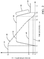
Fig. 2 is graph of a braking-maneuver executed by the system ofFig. 1 in accordance with one embodiment. -
Fig. 1 illustrates a non-limiting example of abrake control system 10, hereafter thesystem 10, which is suitable for operating thebrakes 18 of an automated vehicle, e.g. a host-vehicle 12. As used herein, the term automated vehicle may apply to instances when the host-vehicle 12 is being operated in an automated-mode 14, i.e. a fully autonomous mode, where a human-operator (not shown) of the host-vehicle 12 may do little more than designate a destination in order to operate the host-vehicle 12. However, full automation is not a requirement. It is contemplated that the teachings presented herein are useful when the host-vehicle 12 is operated in a manual-mode 16 where the degree or level of automation may be little more than assisting the human-operator as needed to operate thebrakes 18 to avoid interference with and/or a collision with, for example, another-vehicle. As will be described in more detail below, thesystem 10 described herein is an improvement over prior braking-systems because thesystem 10 provides for improved brake control at slow speed, e.g. at speeds less than five kilometers per hours (5kph). The improvement overcomes the aforementioned problems with using a typical example of a wheel-speed-sensor 20, commercially available examples of which will be known by those in the art. - The
system 10 includes a motion-detector 22 that detects a relative-movement 24 of the host-vehicle 12 relative to a stationary-feature 26 located apart from the host-vehicle 12. As used herein, the phrase 'apart from the host-vehicle 12 means that the stationary-feature 26 is not part of, or is not attached to, the host-vehicle 12. By way of example and not limitation, the stationary-feature 26 maybe a road-surface 28 of a roadway (not shown) upon which the host-vehicle 12 is traveling. The motion-detector may be configured to discern the relative-movement 24 of discernable details of the road-surface 28, where the discernable details are found in the texture or imperfections of the road-surface 28. Alternatively, the stationary-feature 26 may be a lane-marking 30, e.g. a lane-division-stripe, a turn-arrow, a cross-walk-marking, or any other taped-on or painted-on marking commonly found on roadways. Furthermore, the stationary-feature 26 may be anobject 32, such as a sign, a lamp-post, or a curb. The relative-movement 24 is preferably due only to movement of the host-vehicle 12 which presumes that the stationary-feature 26 is indeed stationary, e.g. is not another moving vehicle. If an other-vehicle is verified to be stopped because it is, for example, waiting at red traffic-signal and the brake lights of the other-vehicle are illuminated, then it is contemplated that the other-vehicle may be used as the stationary-feature 26. - The system includes a
controller 34 configured to operate thebrakes 18 of the host-vehicle 12. Thecontroller 34 may include a processor (not specifically shown) such as a microprocessor or other control circuitry such as analog and/or digital control circuitry including an application specific integrated circuit (ASIC) for processing data as should be evident to those in the art. Thecontroller 34 may include memory (not specifically shown), including non-volatile memory, such as electrically erasable programmable read-only memory (EEPROM) for storing one or more routines, thresholds, and captured data. The one or more routines may be executed by the processor to perform steps for controlling thebrakes 18 based on signals received by thecontroller 34 from, but not limited to, the wheel-speed-sensor 20, and/or the motion-detector 22 as described herein. - As noted above, it is known to regulate the brake-pressure 36 (e.g. the pressure of hydraulic brake-fluid, or the force applied to brake-pads by an actuator) of the
brakes 18 based on a signal from the wheel-speed-sensor 20. However, common configurations of the wheel-speed-sensor 20 generate pulses in response to, for example, the passing of teeth on a toothed-wheel or slotted-wheel that is mechanically coupled to the wheel of interest. As the vehicle-speed 38 approaches zero, the time between successive pulses may be too far apart for a brake-control-system to provide for a smooth stop. Thesystem 10 described herein, or more specifically thecontroller 34, improves automated braking performance at slow speeds (e.g. <5kph) because thecontroller 34 determines the vehicle-speed 38 of the host-vehicle 12 based on the relative-movement 24 determined using the motion-detector 22 when the vehicle-speed 38 is less than a speed-threshold 40. That is, during a braking-maneuver when the vehicle-speed 38 slows to less than the speed-threshold 40, thecontroller 34 regulates the brake-pressure 36 of thebrakes 18 based on information or a signal from the motion-detector 22. - In one embodiment, the motion-
detector 22 may include or may be formed of acamera 42 mounted on the host-vehicle 12 so that thecamera 42 is oriented toward the road-surface 28 proximate to (e.g. immediately in front of, within two meters of) the host-vehicle 12. The road-surface serves as the stationary-feature and images rendered by the camera at different times are analyzed using, for example, motion-flow-analysis to determine how much the road-surface 28 appears to move in the images. From the images the vehicle-speed 38 can be determined as will be recognized by those in the art. It is contemplated that the camera may include an infrared-light to illuminate the road-surface 28. - In another embodiment, the motion-
detector 22 may include or may be formed of a light-source 44 that directs light toward a road-surface proximate to the host-vehicle, and an array of light-detectors 46 that detect a pattern-of-light reflected by the road-surface 28. The combination of the light-source 44 and the array of light-detectors 46 is similar to that use in an optical-mouse for a person to control the position of a cursor on a computer display. Preferably, the light-source 44 emits infrared-light so the illumination by the light-source 44 is not detectable by human-vision. As used herein, the array of light-detectors 46 is envisioned to be limited to a relatively small number of pixels, and 18x18 array for example, so is not to be confused with thecamera 42, which those in the art would instantly recognize to have arrays of more than 100x100 pixels. - In another embodiment, the motion-
detector 22 may include or may be formed of aradar 48 mounted on the host-vehicle 12. Theradar 48 is preferably oriented to detect instances of theobjects 32 such as a sign, a lamp-post, or a curb proximate to the host-vehicle 12. As will be recognized by those in the art, radars in general are able to detect a range-rate of an object, from which the vehicle-speed 38 is readily determined. Alternatively, the motion-detector 22 may include or may be formed of alidar 50 that is also suitable to determine a range-rate of an object. It is further contemplated that any combination of the above device implementations of the motion-detector 22 may be used to determine the vehicle-speed 38 when the vehicle-speed 38 is less than the speed-threshold 40, and that any combination of the road-surface 28, the lane-marking 30, theobject 32, and/or anything that could be characterized as stationary with respect to the roadway can be used as the stationary-feature 26. -
Fig. 2 illustrates a graph 52 that illustrates data related to a non-limiting example of a braking-maneuver executed by thesystem 10 to stop the host-vehicle 12. At time T0 the host-vehicle 12 is traveling at an initial-speed 54 of thirty-five kilometers-per-hour (35kph). At time T1 the system begins to increase the brake-pressure 36 to an initial-pressure 56. The initial-pressure 56 may be selected or calculated based on a variety of factors that may include, but are not limited to, a stop-distance (the distance to a location before which the host-vehicle 12 must be stopped), a road-slope (e.g. is the roadway sloped downhill so the stopping distance is increased), traction (is the roadway dry or wet/icy), and vehicle-load (e.g. the host-vehicle 12 is heavily loaded and/or is towing a trailer). - At time T2 the vehicle-
speed 38 decreases below the threshold-speed 40, 5kph in this non-limiting example. Prior to time T2 the vehicle-speed 38 is monitored by the wheel-speed-sensor 20, and optionally by the motion-detector 22. That is, it is not a requirement that only the wheel-speed-sensor 20 be used to determine the vehicle-speed 38 when the vehicle-speed 38 is greater than the threshold-speed 40. Because the update-rate of many commercially available examples of the wheel-speed-sensor 20 is too low for precise brake-control, the motion-detector 22 is the preferred means to determine the vehicle-speed 38 when the vehicle-speed 38 is less than the speed-threshold 40. - At time T2 the vehicle-
speed 38 decreases below a near-stop-speed, 2kph for example. It is not desirable to maintain a constant value of the brake-pressure 36 until the host-vehicle 12 comes to a complete stop as this will impart an unpleasant jerk to any passenger of the host-vehicle 12. Accordingly, the brake-pressure 38 is reduced when the relative-speed 24 (i.e. the vehicle-speed 38) is less than the near-stop-speed 58. That is, thesystem 10 applies a let-up 60 of the brake-pressure 36 for smooth stop. Preferably, the brake-pressure 36 at the instant the host-vehicle 12 stops at time T4 is a holding-pressure 62 which is just enough to keep the host-vehicle 12 stopped until thebrakes 18 are released. - Accordingly, a brake control system (the system 10), a
controller 34 for thesystem 10, and a method of operating thesystem 10 is provided. The improved ability of the system to determine the vehicle-speed 36 while the host-vehicle is moving slowly, less than 5kph for example, allows for smoother automated braking of the host-vehicle 12. - While this invention has been described in terms of the preferred embodiments thereof, it is not intended to be so limited, but rather only to the extent set forth in the claims that follow.
- Although the present invention is defined in the attached claims, it should be understood that the present invention can also (alternatively) be defined in accordance with the following embodiments:
- 1. A brake control system (10) for operating brakes (18) of an automated vehicle at slow speed, said system (10) comprising:
- a motion-detector (22) that detects relative-movement (24) of a host-vehicle (12) relative to a stationary-feature (26) located apart from the host-vehicle (12); and
- a controller (34) configured to operate brakes (18) of the host-vehicle (12), wherein the controller (34) determines a vehicle-speed (36) of the host-vehicle (12) based on the relative-movement (24) when the vehicle-speed (36) is less than a speed-threshold (40), and regulates brake-pressure (36) of the brakes (18) based on the vehicle-speed (36).
- 2. The system (10) in accordance with embodiment 1, wherein the motion-detector (22) includes a camera (42) mounted on the host-vehicle (12), and the camera (42) is oriented toward a road-surface (28) proximate to the host-vehicle (12), whereby the road-surface (28) is the stationary-feature (26).
- 3. The system (10) in accordance with embodiment 1, wherein the motion-detector (22) includes a light-source (44) that directs light toward a road-surface (28) proximate to the host-vehicle (12), and an array of light-detectors (46) that detect a pattern-of-light reflected by the road-surface (28), whereby a road-surface (28) is the stationary-feature (26).
- 4. The system (10) in accordance with embodiment 1, wherein the motion-detector (22) includes a radar (48) mounted on the host-vehicle (12), and the radar (48) is oriented to detect objects (32) proximate to the host-vehicle (12), whereby an object (32) proximate to the host-vehicle (12) is the stationary-feature (26).
- 5. The system (10) in accordance with embodiment 1, wherein the brake-pressure (36) is reduced when the relative-speed (24) is less than a near-stop-speed (58).
Claims (18)
- A brake control system for operating brakes of an automated vehicle, the brake control system comprising:a motion-detector that detects relative-movement of a host-vehicle relative to a stationary-feature located apart from the host-vehicle, wherein the host-vehicle includes a wheel-speed-sensor, brakes, and vehicle controls for operating the brakes; anda controller communicatively coupled to the motion-detector, the wheel-speed-sensor, and the vehicle controls of the host-vehicle, the controller configured to operate the brakes by using the vehicle controls of the host-vehicle when the host-vehicle is operated in an automated-mode, wherein the controller determines a vehicle-speed of the host-vehicle based on the relative-movement detected by the motion-detector when the vehicle-speed is less than a speed-threshold, and regulates brake-pressure of the brakes based on the vehicle-speed.
- The brake control system of claim 1, wherein the motion-detector includes a camera mounted on the host-vehicle, and the camera is oriented toward a road-surface proximate to the host-vehicle, and wherein the road-surface is the stationary-feature.
- The brake control system of claims 1 or 2, wherein the motion-detector includes a light-source that directs light toward a road-surface proximate to the host-vehicle, and an array of light-detectors that detect a pattern-of-light reflected by the road-surface, and wherein a road-surface is the stationary-feature.
- The brake control system of any of claims 1-3, wherein the motion-detector includes a radar mounted on the host-vehicle, and the radar is oriented to detect objects proximate to the host-vehicle, and wherein an object proximate to the host-vehicle is the stationary-feature.
- The brake control system of any of claims 1-4, wherein the brake-pressure is reduced when the vehicle-speed is less than a near-stop-speed threshold.
- The brake control system of any of claims 1-5, wherein the controller determines the vehicle-speed of the host-vehicle by using the wheel-speed-sensor when the vehicle-speed is at or above the speed-threshold, wherein an update-rate of the motion-detector is greater than an update-rate of the wheel-speed-sensor when the vehicle-speed is less than the speed-threshold.
- The brake control system of any of claims 1-6, wherein the stationary-feature includes at least one of a stationary roadway object proximate to the host-vehicle, a road-surface, and a lane-marking.
- The brake control system of claim 7, wherein the stationary roadway object includes a sign, a lamp-post, or a curb.
- The brake control system of any of claims 1-8, wherein the controller regulates the brake-pressure of the brakes by reducing the brake-pressure when the vehicle-speed is less than the speed-threshold.
- A method for operating brakes of an automated vehicle, the method comprising:detecting, by a motion-detector, relative-movement of a host-vehicle relative to a stationary-feature located apart from the host-vehicle, wherein the host-vehicle includes a wheel-speed-sensor, brakes, and vehicle controls for operating the brakes;determining, by a controller communicatively coupled to the motion-detector, the wheel-speed-sensor, and the vehicle controls of the host-vehicle, a vehicle-speed of the host-vehicle based on the relative-movement detected by the motion-detector when the vehicle-speed is less than a speed-threshold, wherein the controller is configured to operate the brakes by using the vehicle controls of the host-vehicle when the host-vehicle is operated in an automated-mode; andregulating, by the controller, brake-pressure of the brakes based on the vehicle-speed.
- The method of claim 10, wherein the motion-detector includes a camera mounted on the host-vehicle, and the camera is oriented toward a road-surface proximate to the host-vehicle, and wherein the road-surface is the stationary-feature.
- The method of claims 10 or 11, wherein the motion-detector includes a light-source that directs light toward a road-surface proximate to the host-vehicle, and an array of light-detectors that detect a pattern-of-light reflected by the road-surface, and wherein a road-surface is the stationary-feature.
- The method of any of claims 10-12, wherein the motion-detector includes a radar mounted on the host-vehicle, and the radar is oriented to detect objects proximate to the host-vehicle, and wherein an object proximate to the host-vehicle is the stationary-feature.
- The method of any of claims 10-13, wherein the brake-pressure is reduced when the vehicle-speed is less than a near-stop-speed threshold.
- The method of any of claims 10-14, further comprising determining, by the controller, the vehicle-speed of the host-vehicle by using the wheel-speed-sensor when the vehicle-speed is at or above the speed-threshold, wherein an update-rate of the motion-detector is greater than an update-rate of the wheel-speed-sensor when the vehicle-speed is less than the speed-threshold.
- The method of any of claims 10-15, wherein the stationary-feature includes at least one of a stationary roadway object proximate to the host-vehicle, a road-surface, and a lane-marking.
- The method of claim 16, wherein the stationary roadway object includes a sign, a lamp-post, or a curb.
- The method of any of claims 10-17, wherein regulating the brake-pressure of the brakes comprises reducing, by the controller, the brake-pressure when the vehicle-speed is less than the speed-threshold.
Applications Claiming Priority (1)
| Application Number | Priority Date | Filing Date | Title |
|---|---|---|---|
| US15/619,939 US10384660B2 (en) | 2017-06-12 | 2017-06-12 | Slow speed automated vehicle brake pressure control system |
Publications (1)
| Publication Number | Publication Date |
|---|---|
| EP3415384A1 true EP3415384A1 (en) | 2018-12-19 |
Family
ID=62748707
Family Applications (1)
| Application Number | Title | Priority Date | Filing Date |
|---|---|---|---|
| EP18177228.6A Withdrawn EP3415384A1 (en) | 2017-06-12 | 2018-06-12 | Slow speed automated vehicle brake pressure control system |
Country Status (3)
| Country | Link |
|---|---|
| US (1) | US10384660B2 (en) |
| EP (1) | EP3415384A1 (en) |
| WO (1) | WO2018231715A1 (en) |
Families Citing this family (1)
| Publication number | Priority date | Publication date | Assignee | Title |
|---|---|---|---|---|
| CN109947106B (en) * | 2019-03-29 | 2020-04-24 | 浙江大学 | Stable and reliable intelligent trolley capable of automatically avoiding obstacles and speed control method |
Citations (5)
| Publication number | Priority date | Publication date | Assignee | Title |
|---|---|---|---|---|
| WO2005014350A1 (en) * | 2003-08-06 | 2005-02-17 | Robert Bosch Gbmh | Device for longitudinally guiding a motor vehicle by intervening in the brake system |
| DE102007060858A1 (en) * | 2007-12-13 | 2009-06-18 | Technische Universität Ilmenau | Device and method for determining the state of friction of a road surface |
| WO2012000579A1 (en) * | 2010-06-30 | 2012-01-05 | Wabco Gmbh | Device and method for outputting a signal when there is a hazardous underlying surface under a vehicle |
| US20120239266A1 (en) * | 2011-03-16 | 2012-09-20 | Fuji Jukogyo Kabushiki Kaisha | Vehicle driving support apparatus |
| US20140184785A1 (en) * | 2012-12-28 | 2014-07-03 | Robert Bosch Gmbh | Vehicle standstill recognition |
Family Cites Families (5)
| Publication number | Priority date | Publication date | Assignee | Title |
|---|---|---|---|---|
| US7475953B2 (en) | 2006-02-03 | 2009-01-13 | Kelsey-Hayes Company | Soft-stop braking control |
| JP4938598B2 (en) * | 2007-09-06 | 2012-05-23 | トヨタ自動車株式会社 | Vehicle control device |
| DE102009032314A1 (en) * | 2009-07-09 | 2011-01-13 | Wabco Gmbh | Method for the correct execution of autonomous emergency braking in a road vehicle |
| JP6183388B2 (en) * | 2015-02-03 | 2017-08-23 | トヨタ自動車株式会社 | Vehicle control device |
| US9840239B2 (en) | 2015-10-13 | 2017-12-12 | Robert Bosch Gmbh | Cornering brake control |
-
2017
- 2017-06-12 US US15/619,939 patent/US10384660B2/en active Active
-
2018
- 2018-06-11 WO PCT/US2018/036931 patent/WO2018231715A1/en active Application Filing
- 2018-06-12 EP EP18177228.6A patent/EP3415384A1/en not_active Withdrawn
Patent Citations (5)
| Publication number | Priority date | Publication date | Assignee | Title |
|---|---|---|---|---|
| WO2005014350A1 (en) * | 2003-08-06 | 2005-02-17 | Robert Bosch Gbmh | Device for longitudinally guiding a motor vehicle by intervening in the brake system |
| DE102007060858A1 (en) * | 2007-12-13 | 2009-06-18 | Technische Universität Ilmenau | Device and method for determining the state of friction of a road surface |
| WO2012000579A1 (en) * | 2010-06-30 | 2012-01-05 | Wabco Gmbh | Device and method for outputting a signal when there is a hazardous underlying surface under a vehicle |
| US20120239266A1 (en) * | 2011-03-16 | 2012-09-20 | Fuji Jukogyo Kabushiki Kaisha | Vehicle driving support apparatus |
| US20140184785A1 (en) * | 2012-12-28 | 2014-07-03 | Robert Bosch Gmbh | Vehicle standstill recognition |
Also Published As
| Publication number | Publication date |
|---|---|
| US20180354480A1 (en) | 2018-12-13 |
| WO2018231715A1 (en) | 2018-12-20 |
| US10384660B2 (en) | 2019-08-20 |
Similar Documents
| Publication | Publication Date | Title |
|---|---|---|
| US10576972B2 (en) | Vehicle driving assist control method and control device | |
| CN107415945B (en) | Automatic driving system for evaluating lane change and using method thereof | |
| US10000208B2 (en) | Vehicle control apparatus | |
| CN107531239B (en) | Method and device for regulating the speed of a vehicle | |
| US8615357B2 (en) | Method for assisting a user of a vehicle, control device for a driver-assistance system of a vehicle and vehicle having such a control device | |
| US10025311B2 (en) | Automated vehicle sensor control system | |
| US20150251659A1 (en) | Friction Coefficient Estimation from Camera and Wheel Speed Data | |
| US11807229B2 (en) | Vehicle braking support device and braking support control method | |
| US11072328B2 (en) | Control-target vehicle setting apparatus, control-target vehicle setting system, and control-target vehicle setting method | |
| US11420622B2 (en) | Driving assistance apparatus | |
| US11214239B2 (en) | Driving support apparatus | |
| US10040449B2 (en) | Method for avoiding a rear-end collision between a first vehicle and a second vehicle and control unit | |
| CN113147747A (en) | Apparatus for assisting vehicle driving and method thereof | |
| US11975715B2 (en) | Driving assistance apparatus | |
| US20210380083A1 (en) | Braking assist control device, braking assist system, and braking assist control method for vehicle | |
| EP3415384A1 (en) | Slow speed automated vehicle brake pressure control system | |
| CN111152786A (en) | Driving support device | |
| US20160110620A1 (en) | Method for Triggering a Driver Assistance Function Upon Detection of a Stop Light by Means of a Camera | |
| US20230140246A1 (en) | Driver assistance system and driver assistance method | |
| KR20210080717A (en) | Driver assistance apparatus and driver assisting method | |
| US11912127B2 (en) | Method for controlling a vehicle | |
| KR102436850B1 (en) | Method and apparatus for controlling acc which controls engine torque before starting vehicle based on surrounding environment | |
| JP5018411B2 (en) | Vehicle tracking device | |
| CN111319620A (en) | Vehicle and control method thereof | |
| JP3266832B2 (en) | Recognition method of objects in vehicles |
Legal Events
| Date | Code | Title | Description |
|---|---|---|---|
| PUAI | Public reference made under article 153(3) epc to a published international application that has entered the european phase |
Free format text: ORIGINAL CODE: 0009012 |
|
| STAA | Information on the status of an ep patent application or granted ep patent |
Free format text: STATUS: REQUEST FOR EXAMINATION WAS MADE |
|
| 17P | Request for examination filed |
Effective date: 20180612 |
|
| AK | Designated contracting states |
Kind code of ref document: A1 Designated state(s): AL AT BE BG CH CY CZ DE DK EE ES FI FR GB GR HR HU IE IS IT LI LT LU LV MC MK MT NL NO PL PT RO RS SE SI SK SM TR |
|
| AX | Request for extension of the european patent |
Extension state: BA ME |
|
| RAP1 | Party data changed (applicant data changed or rights of an application transferred) |
Owner name: APTIV TECHNOLOGIES LIMITED |
|
| STAA | Information on the status of an ep patent application or granted ep patent |
Free format text: STATUS: THE APPLICATION IS DEEMED TO BE WITHDRAWN |
|
| 18D | Application deemed to be withdrawn |
Effective date: 20190620 |