EP3415122B1 - Method for producing a stent - Google Patents
Method for producing a stent Download PDFInfo
- Publication number
- EP3415122B1 EP3415122B1 EP18185569.3A EP18185569A EP3415122B1 EP 3415122 B1 EP3415122 B1 EP 3415122B1 EP 18185569 A EP18185569 A EP 18185569A EP 3415122 B1 EP3415122 B1 EP 3415122B1
- Authority
- EP
- European Patent Office
- Prior art keywords
- stent
- cells
- expanded state
- accordance
- shape
- Prior art date
- Legal status (The legal status is an assumption and is not a legal conclusion. Google has not performed a legal analysis and makes no representation as to the accuracy of the status listed.)
- Active
Links
- 238000004519 manufacturing process Methods 0.000 title claims description 7
- 210000000056 organ Anatomy 0.000 claims description 13
- 238000000034 method Methods 0.000 claims description 9
- 239000000463 material Substances 0.000 claims description 5
- 210000004204 blood vessel Anatomy 0.000 claims description 3
- 210000003445 biliary tract Anatomy 0.000 claims description 2
- 210000001072 colon Anatomy 0.000 claims description 2
- 210000001198 duodenum Anatomy 0.000 claims description 2
- 238000010438 heat treatment Methods 0.000 claims description 2
- 238000002513 implantation Methods 0.000 claims description 2
- 210000000626 ureter Anatomy 0.000 claims description 2
- 238000004873 anchoring Methods 0.000 description 11
- 239000003550 marker Substances 0.000 description 11
- 238000005520 cutting process Methods 0.000 description 4
- 238000005452 bending Methods 0.000 description 3
- 238000003780 insertion Methods 0.000 description 3
- 230000037431 insertion Effects 0.000 description 3
- 229910052751 metal Inorganic materials 0.000 description 3
- 239000002184 metal Substances 0.000 description 3
- 210000003111 iliac vein Anatomy 0.000 description 2
- 230000008093 supporting effect Effects 0.000 description 2
- 229910052715 tantalum Inorganic materials 0.000 description 2
- GUVRBAGPIYLISA-UHFFFAOYSA-N tantalum atom Chemical compound [Ta] GUVRBAGPIYLISA-UHFFFAOYSA-N 0.000 description 2
- 230000007704 transition Effects 0.000 description 2
- 210000003462 vein Anatomy 0.000 description 2
- 206010058990 Venous occlusion Diseases 0.000 description 1
- 230000001154 acute effect Effects 0.000 description 1
- 230000006978 adaptation Effects 0.000 description 1
- 230000005540 biological transmission Effects 0.000 description 1
- 238000009826 distribution Methods 0.000 description 1
- 230000000694 effects Effects 0.000 description 1
- 230000008030 elimination Effects 0.000 description 1
- 238000003379 elimination reaction Methods 0.000 description 1
- 210000003238 esophagus Anatomy 0.000 description 1
- 150000002739 metals Chemical class 0.000 description 1
- 239000002994 raw material Substances 0.000 description 1
- 238000009827 uniform distribution Methods 0.000 description 1
- 210000001631 vena cava inferior Anatomy 0.000 description 1
- 230000003313 weakening effect Effects 0.000 description 1
Images
Classifications
-
- A—HUMAN NECESSITIES
- A61—MEDICAL OR VETERINARY SCIENCE; HYGIENE
- A61F—FILTERS IMPLANTABLE INTO BLOOD VESSELS; PROSTHESES; DEVICES PROVIDING PATENCY TO, OR PREVENTING COLLAPSING OF, TUBULAR STRUCTURES OF THE BODY, e.g. STENTS; ORTHOPAEDIC, NURSING OR CONTRACEPTIVE DEVICES; FOMENTATION; TREATMENT OR PROTECTION OF EYES OR EARS; BANDAGES, DRESSINGS OR ABSORBENT PADS; FIRST-AID KITS
- A61F2/00—Filters implantable into blood vessels; Prostheses, i.e. artificial substitutes or replacements for parts of the body; Appliances for connecting them with the body; Devices providing patency to, or preventing collapsing of, tubular structures of the body, e.g. stents
- A61F2/82—Devices providing patency to, or preventing collapsing of, tubular structures of the body, e.g. stents
- A61F2/86—Stents in a form characterised by the wire-like elements; Stents in the form characterised by a net-like or mesh-like structure
- A61F2/90—Stents in a form characterised by the wire-like elements; Stents in the form characterised by a net-like or mesh-like structure characterised by a net-like or mesh-like structure
- A61F2/91—Stents in a form characterised by the wire-like elements; Stents in the form characterised by a net-like or mesh-like structure characterised by a net-like or mesh-like structure made from perforated sheet material or tubes, e.g. perforated by laser cuts or etched holes
- A61F2/915—Stents in a form characterised by the wire-like elements; Stents in the form characterised by a net-like or mesh-like structure characterised by a net-like or mesh-like structure made from perforated sheet material or tubes, e.g. perforated by laser cuts or etched holes with bands having a meander structure, adjacent bands being connected to each other
- A61F2002/91525—Stents in a form characterised by the wire-like elements; Stents in the form characterised by a net-like or mesh-like structure characterised by a net-like or mesh-like structure made from perforated sheet material or tubes, e.g. perforated by laser cuts or etched holes with bands having a meander structure, adjacent bands being connected to each other within the whole structure different bands showing different meander characteristics, e.g. frequency or amplitude
-
- A—HUMAN NECESSITIES
- A61—MEDICAL OR VETERINARY SCIENCE; HYGIENE
- A61F—FILTERS IMPLANTABLE INTO BLOOD VESSELS; PROSTHESES; DEVICES PROVIDING PATENCY TO, OR PREVENTING COLLAPSING OF, TUBULAR STRUCTURES OF THE BODY, e.g. STENTS; ORTHOPAEDIC, NURSING OR CONTRACEPTIVE DEVICES; FOMENTATION; TREATMENT OR PROTECTION OF EYES OR EARS; BANDAGES, DRESSINGS OR ABSORBENT PADS; FIRST-AID KITS
- A61F2/00—Filters implantable into blood vessels; Prostheses, i.e. artificial substitutes or replacements for parts of the body; Appliances for connecting them with the body; Devices providing patency to, or preventing collapsing of, tubular structures of the body, e.g. stents
- A61F2/82—Devices providing patency to, or preventing collapsing of, tubular structures of the body, e.g. stents
- A61F2/86—Stents in a form characterised by the wire-like elements; Stents in the form characterised by a net-like or mesh-like structure
- A61F2/90—Stents in a form characterised by the wire-like elements; Stents in the form characterised by a net-like or mesh-like structure characterised by a net-like or mesh-like structure
- A61F2/91—Stents in a form characterised by the wire-like elements; Stents in the form characterised by a net-like or mesh-like structure characterised by a net-like or mesh-like structure made from perforated sheet material or tubes, e.g. perforated by laser cuts or etched holes
- A61F2/915—Stents in a form characterised by the wire-like elements; Stents in the form characterised by a net-like or mesh-like structure characterised by a net-like or mesh-like structure made from perforated sheet material or tubes, e.g. perforated by laser cuts or etched holes with bands having a meander structure, adjacent bands being connected to each other
- A61F2002/9155—Adjacent bands being connected to each other
- A61F2002/91575—Adjacent bands being connected to each other connected peak to trough
-
- A—HUMAN NECESSITIES
- A61—MEDICAL OR VETERINARY SCIENCE; HYGIENE
- A61F—FILTERS IMPLANTABLE INTO BLOOD VESSELS; PROSTHESES; DEVICES PROVIDING PATENCY TO, OR PREVENTING COLLAPSING OF, TUBULAR STRUCTURES OF THE BODY, e.g. STENTS; ORTHOPAEDIC, NURSING OR CONTRACEPTIVE DEVICES; FOMENTATION; TREATMENT OR PROTECTION OF EYES OR EARS; BANDAGES, DRESSINGS OR ABSORBENT PADS; FIRST-AID KITS
- A61F2/00—Filters implantable into blood vessels; Prostheses, i.e. artificial substitutes or replacements for parts of the body; Appliances for connecting them with the body; Devices providing patency to, or preventing collapsing of, tubular structures of the body, e.g. stents
- A61F2/82—Devices providing patency to, or preventing collapsing of, tubular structures of the body, e.g. stents
- A61F2/86—Stents in a form characterised by the wire-like elements; Stents in the form characterised by a net-like or mesh-like structure
- A61F2/90—Stents in a form characterised by the wire-like elements; Stents in the form characterised by a net-like or mesh-like structure characterised by a net-like or mesh-like structure
- A61F2/91—Stents in a form characterised by the wire-like elements; Stents in the form characterised by a net-like or mesh-like structure characterised by a net-like or mesh-like structure made from perforated sheet material or tubes, e.g. perforated by laser cuts or etched holes
- A61F2/915—Stents in a form characterised by the wire-like elements; Stents in the form characterised by a net-like or mesh-like structure characterised by a net-like or mesh-like structure made from perforated sheet material or tubes, e.g. perforated by laser cuts or etched holes with bands having a meander structure, adjacent bands being connected to each other
- A61F2002/9155—Adjacent bands being connected to each other
- A61F2002/91583—Adjacent bands being connected to each other by a bridge, whereby at least one of its ends is connected along the length of a strut between two consecutive apices within a band
-
- A—HUMAN NECESSITIES
- A61—MEDICAL OR VETERINARY SCIENCE; HYGIENE
- A61F—FILTERS IMPLANTABLE INTO BLOOD VESSELS; PROSTHESES; DEVICES PROVIDING PATENCY TO, OR PREVENTING COLLAPSING OF, TUBULAR STRUCTURES OF THE BODY, e.g. STENTS; ORTHOPAEDIC, NURSING OR CONTRACEPTIVE DEVICES; FOMENTATION; TREATMENT OR PROTECTION OF EYES OR EARS; BANDAGES, DRESSINGS OR ABSORBENT PADS; FIRST-AID KITS
- A61F2230/00—Geometry of prostheses classified in groups A61F2/00 - A61F2/26 or A61F2/82 or A61F9/00 or A61F11/00 or subgroups thereof
- A61F2230/0002—Two-dimensional shapes, e.g. cross-sections
- A61F2230/0017—Angular shapes
- A61F2230/0026—Angular shapes trapezoidal
-
- A—HUMAN NECESSITIES
- A61—MEDICAL OR VETERINARY SCIENCE; HYGIENE
- A61F—FILTERS IMPLANTABLE INTO BLOOD VESSELS; PROSTHESES; DEVICES PROVIDING PATENCY TO, OR PREVENTING COLLAPSING OF, TUBULAR STRUCTURES OF THE BODY, e.g. STENTS; ORTHOPAEDIC, NURSING OR CONTRACEPTIVE DEVICES; FOMENTATION; TREATMENT OR PROTECTION OF EYES OR EARS; BANDAGES, DRESSINGS OR ABSORBENT PADS; FIRST-AID KITS
- A61F2240/00—Manufacturing or designing of prostheses classified in groups A61F2/00 - A61F2/26 or A61F2/82 or A61F9/00 or A61F11/00 or subgroups thereof
- A61F2240/001—Designing or manufacturing processes
-
- A—HUMAN NECESSITIES
- A61—MEDICAL OR VETERINARY SCIENCE; HYGIENE
- A61F—FILTERS IMPLANTABLE INTO BLOOD VESSELS; PROSTHESES; DEVICES PROVIDING PATENCY TO, OR PREVENTING COLLAPSING OF, TUBULAR STRUCTURES OF THE BODY, e.g. STENTS; ORTHOPAEDIC, NURSING OR CONTRACEPTIVE DEVICES; FOMENTATION; TREATMENT OR PROTECTION OF EYES OR EARS; BANDAGES, DRESSINGS OR ABSORBENT PADS; FIRST-AID KITS
- A61F2250/00—Special features of prostheses classified in groups A61F2/00 - A61F2/26 or A61F2/82 or A61F9/00 or A61F11/00 or subgroups thereof
- A61F2250/0014—Special features of prostheses classified in groups A61F2/00 - A61F2/26 or A61F2/82 or A61F9/00 or A61F11/00 or subgroups thereof having different values of a given property or geometrical feature, e.g. mechanical property or material property, at different locations within the same prosthesis
- A61F2250/0037—Special features of prostheses classified in groups A61F2/00 - A61F2/26 or A61F2/82 or A61F9/00 or A61F11/00 or subgroups thereof having different values of a given property or geometrical feature, e.g. mechanical property or material property, at different locations within the same prosthesis differing in height or in length
-
- A—HUMAN NECESSITIES
- A61—MEDICAL OR VETERINARY SCIENCE; HYGIENE
- A61F—FILTERS IMPLANTABLE INTO BLOOD VESSELS; PROSTHESES; DEVICES PROVIDING PATENCY TO, OR PREVENTING COLLAPSING OF, TUBULAR STRUCTURES OF THE BODY, e.g. STENTS; ORTHOPAEDIC, NURSING OR CONTRACEPTIVE DEVICES; FOMENTATION; TREATMENT OR PROTECTION OF EYES OR EARS; BANDAGES, DRESSINGS OR ABSORBENT PADS; FIRST-AID KITS
- A61F2250/00—Special features of prostheses classified in groups A61F2/00 - A61F2/26 or A61F2/82 or A61F9/00 or A61F11/00 or subgroups thereof
- A61F2250/0058—Additional features; Implant or prostheses properties not otherwise provided for
- A61F2250/0096—Markers and sensors for detecting a position or changes of a position of an implant, e.g. RF sensors, ultrasound markers
- A61F2250/0098—Markers and sensors for detecting a position or changes of a position of an implant, e.g. RF sensors, ultrasound markers radio-opaque, e.g. radio-opaque markers
Definitions
- the present invention relates to a method for the production of a stent, such as for transluminal implantation in hollow organs, in particular in blood vessels, ureters, esophagus, colon, duodenum or biliary tract, having a substantially tubular body, which from a compressed state with a first cross-sectional diameter in one expanded state with an enlarged second cross-sectional diameter, wherein the stent comprises a plurality of cells, which are defined by bordering elements formed by the tubular body.
- Stents of this type are used for the recanalization of pathologically altered hollow organs.
- the stents are introduced in the compressed state via an insertion catheter to the treatment site within the hollow organ, where they are expanded by different measures to a diameter corresponding to the diameter of the healthy hollow organ, so that a supporting effect of the hollow organ, such as a vessel wall , is achieved.
- Such stents may be produced, for example, by cutting apertures in the wall of a tubular body, such as slits, which extend partially in the longitudinal direction of the stent such that, for example, diamond-shaped apertures arise during expansion of the stent.
- An opening along with its border elements is called a cell.
- stents When stents are used in the vicinity of a hollow organ bifurcation, stents may be used which have a bevelled end. Such stents offer the possibility, e.g. support a vein on all sides to the bifurcation, i. for example, to the mouth in another vein.
- the stents In order to be able to ensure their supporting effect, the stents must be able to exert a sufficient radial positioning force, which counteracts a force exerted by the vessel wall radial force. This is especially true in the area of the tapered end, since there the radial Aufstellkraft is usually reduced.
- the US 2012/024567 A1 describes one having a substantially tubular body which is convertible from a compressed state having a first cross-sectional diameter to an expanded state having an enlarged second cross-sectional diameter.
- the stent comprises a plurality of cells defined by perimeter members formed by the tubular body. Some of the cells are elongated compared to the other cells in the longitudinal direction of the stent.
- the US 2012/24567 A1 describes a stent which is cut from a tubular material and expanded to an expanded state.
- EP 2594232 describes highly elastic stents and manufacturing processes for highly elastic stents.
- the individual cells can each be shaped so that a uniform Aufdehn the individual cells is achieved. In this way, the risk of breakage can be reduced, in particular in the case of short and medium cells in the vicinity of the beveled region, which usually expand asymmetrically and excessively due to an inhomogeneous force distribution during expansion.
- the acute angles can be reduced or changed so that they are smaller than 70 °, preferably smaller than 60 °.
- the stent can better withstand large external forces in the area of the beveled area by virtue of homogeneous force transmission across the structure and the risk of stent collapse or stent fracture is markedly reduced.
- a core is used for expansion, to which attachment means are attached in order to change and fix the shape of the cells of the stent.
- attachment means With the fasteners so the Aufdehn the individual cells can be adjusted.
- the shape of the cells is thus changed from the expansion in the mere use of, for example, a cylindrical core.
- a cylindrical core may also include a tapered portion that facilitates the deployment of the stent.
- the expansion can be done with heat.
- the fastening means are needles or mandrels which are introduced into holes of the core.
- the needles or mandrels can be moved out of the core from the inside or inserted into the core from the outside.
- an automated process by means of robots or hydraulics, but also a manual adaptation of the cells can be performed.
- the altered shape of the cells of the stent is permanently fixed by means of a heating process.
- a fixation is particularly advantageous in the use of memory metals, which resume the stored by the heat process form when the temperature increases.
- a permanent fixation is understood to mean a fixation of the shape of the cells of the stent in the expanded state of the stent, wherein the shape of the cells is maintained in the expanded state, even if the stent is transferred in the meantime in the compressed state.
- a stent may be used in which a portion of the cells is elongated in the longitudinal direction of the stent compared to the remaining cells to form a bevelled end-face end of the stent.
- a beveled end can be created. In this case, because of the longitudinally elongated cells, no additional cells are needed to form the bevelled end.
- the elongated cells it is possible to select a similar arrangement of the cells in the bevelled area as in the rest of the tubular body.
- the elongated cells can only be present in a rigid section of the stent.
- the stent may e.g. a flexible section and / or anchoring section.
- the following remarks concerning the extended cells refer to the rigid section.
- a stent according to the invention can therefore be used, for example, in the case of venous obstructions in the region of the bifurcation, the confluence of the two common iliac veins into the inferior vena cava, in the upper region of the common iliac vein.
- the stent may have a diameter of greater than or equal to 12 mm.
- the stent may have a diameter between 12 mm and 18 mm.
- the elimination of additional cells allows the angle of the bevel to be set variably since this angle can be determined by the relative lengthening of the elongated cells.
- the bevelled area allows the hollow organ to be reliably supported up to the bifurcation, but without e.g. it is essential to place it in the bloodstream after the bifurcation.
- a cell may be connected to one or more other cells through one or more connection sections.
- the length of a cell may be understood to mean the distance in the longitudinal direction between two connecting sections, wherein in each case the center of the respective connecting section is to be taken into account.
- a cell comprises said recess and its respective bordering elements, the connecting sections belonging to the bordering elements.
- the cells can be connected to each other at least in part by means of a plurality of connecting sections.
- three or four connecting sections may be provided in each case in the bevelled area and / or in the case of the extended cells.
- the support effect can be particularly high by reaching in this way radial Aufstellkraft.
- the stent can be made of a memory metal, which assumes a stored form from a limit temperature.
- At least a portion of the elongate cells may be arranged along a straight or approximately straight line, in particular parallel or approximately parallel to the longitudinal direction. This means that, for example, at least one or two cells arranged one behind the other on the straight line can be provided. With more than two cells, at least two connecting sections of at least one of these cells can be directly connected to two further of the extended cells. In particular, each two connecting portions of the elongated cells lie on the straight line.
- the elongate cells may be divisible into a plurality of groups, in particular into nine groups, the cells of each group being arranged along a straight or approximately straight line, respectively, and these lines being in particular parallel or approximately parallel to the longitudinal direction.
- the stent may have twelve groups of cells, nine of which have extended cells. In such a definition of groups, the spaces between the groups themselves may also form cells.
- the arrangement of the cells can thus be chosen such that the respective cells are arranged along straight or approximately straight lines.
- the cells may be symmetrical to one of these lines. In particular, therefore, there can be no cells which are inclined or rotated relative to the remaining cells. In this way, weakening of the structure by such rotated cells can be avoided.
- all cells within a group viewed in the longitudinal direction may each have the same or approximately the same length.
- cells of different lengths may also be provided in a group.
- the lines formed by the cells of different groups may be parallel or approximately parallel to each other.
- each group From a cross-sectional plane extending perpendicularly to the longitudinal axis up to the bevelled end-side end, in each case the same number of cells can be provided in each group.
- a radial setting-up force can be effected, which is essentially constant over the length of the stent.
- the same number of cells can be provided in the rigid section of the stent in each group.
- angles when using the same number of cells can be formed by the connecting portions of the cells each angle, which can be seen in the so-called development of the stent.
- the angles are defined by the circumferential direction (which in the settlement is a straight line) and a straight line, the straight line passing through connecting sections of the cells. This means that the connection sections of at least a part of the cells in the development lie on straight lines.
- the angles can be bigger The closer the angle is to the beveled end of the stent, four, five or six angles are preferred.
- the ends of the cells in the development can not form a straight line, but define a curve which approximates a sine curve.
- a sinusoidal curve in the development leads on the three-dimensional stent to an oblique incision (the chamfered area) with an exactly flat cut surface.
- the cells may be arranged so that a first angle in a range between 20 ° and 24 °, a second angle in a range between 37 ° and 44 °, a third angle in a range between 48 ° and 52 °, a fourth angle in a range between 60 ° and 64 °, a fifth angle in a range between 63 ° and 67 ° and a sixth angle in a range between 69 ° and 73 °.
- the greatest angle may be closest to the beveled end of the stent, whereas the smallest angle is farthest from the bevelled end.
- an angle of 0 ° may be provided, that is, a position exists on the stent in the unwinding, on which connecting portions are arranged along the circumferential direction.
- the angle of 0 ° may be provided at a transition from the rigid area to the flexible area.
- the cells of a group may be of different lengths to form the described angles.
- the length of the cells of adjacent groups in the circumferential direction may fall from a maximum to a minimum.
- cells are at maximum Length cells of minimal length with respect to a central axis of the stent opposite.
- the cells may be connected to one another at least in part by means of connecting sections, wherein the connecting sections between the extended cells, in particular only between the longest cells, are formed extended. Due to the enlarged or enlarged connecting portions, the openings of the longest cells can be shortened, whereby a uniform bending of all cells can be achieved during expansion of the stent. Such a uniform bending in turn can lead to a uniform distribution of the radial erection force and to a particularly robust stent.
- At least one marker may extend longitudinally from the bevelled end, in particular in the form of an eyelet, the marker having an asymmetrical shape.
- a marker may be a portion of the stent having increased radiopacity, i. is particularly visible in an X-ray image.
- the marker may be an eyelet filled or covered, for example, with tantalum. Because of the asymmetrical shape, the marker can also be mounted in the bevelled area because the marker can extend away from the taper.
- the marker can thus be arranged in a region between the longest and the shortest extent of the stent in the longitudinal direction. Due to the asymmetrical shape of the marker can be made large enough to be particularly well recognized in the X-ray image.
- another marker may be provided, for example, at the top of the chamfer.
- Yet another marker may, for example, be attached to the chamfer at a shortest point of the stent.
- At least two asymmetrical markers may be provided at the beveled end, with the markers in particular facing one another with respect to an axis of the stent.
- the two markers may be symmetrical about a plane of the stent which passes through an axis of the stent and a peak of the chamfer. Due to such an arrangement, the asymmetrical markers can be brought into coincidence in an X-ray image, for example. As a consequence, the position of the stent in the x-ray image can be particularly well recognized.
- the stent may include a flexible portion that connects to the rigid portion.
- the flexible portion is opposite the tapered end.
- the flexible portion may have cells which have a larger area in the development than cells of the rigid portion. Due to the larger cells, the flexible portion can be more easily bendable, whereby the flexible portion can easily adapt to the shape of a hollow organ.
- the cells of the flexible portion may have a tooth-shaped boundary.
- the stent may include an anchoring portion that adjoins the flexible portion.
- the cells of the anchoring portion may correspond to the cells of the rigid portion and may be diamond-shaped, for example.
- the anchoring portion may have a low flexibility due to the rhombic cells and thus fix the stent in position in the hollow organ.
- the anchoring portion may form a straight end of the stent to which markers may be attached extending from one end of the stent.
- the markers may have the form of eyelets and may also be covered or filled with tantalum, for example.
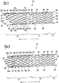
- Fig. 1 and Fig. 2 show a stent 10.
- the stent 10 has a tubular shape and includes a rigid portion 12, a flexible portion 14 adjoining the rigid portion 12, and an anchoring portion 16 adjacent to the flexible portion 14.
- the rigid portion 12 is formed of diamond-shaped (closed) cells 18, which are each connected via three or four connecting portions 20 with other diamond-shaped cells 18.
- the diamond-shaped cells 18 are defined by web-like border elements 22, which are formed from a metal.
- the rigid portion 12 includes a beveled portion 24 which allows insertion of the stent 10 on a bifurcation of a hollow organ (not shown).
- the chamfered portion 24 forms an end of the stent 10 and is formed by making part of the diamond-shaped cells 18 extended in a longitudinal direction L.
- the longest rhombic cells 18 are identified by the reference numeral 18a in the figures, whereas the shortest rhombic cells 18 are identified by the reference numeral 18b.
- three of the shortest diamond-shaped cells 18 b and three of the longest diamond-shaped cells 18 a are provided in the longitudinal direction L, respectively.
- the longest diamond-shaped cells 18a lie opposite the shorter diamond-shaped cells 18b with respect to a central axis of the stent 10.
- Each of three groups of the longest and shortest diamond-shaped cells 18a, 18b are provided side by side (i.e., circumferentially adjacent).
- open cells 26 are arranged with a serrated outline, with less open serrated cells 26 seen in the circumferential direction of the stent 10 than diamond-shaped cells 18.
- the flexible portion is lighter with respect to the longitudinal direction L deformable and can thus adapt well to the course of a bloodstream or the like.
- the anchoring portion 16 is formed by rhombic cells 18, which provide increased rigidity of the anchoring portion 16, whereby the stent 10 reliably maintains its position in a hollow organ.
- Two of the markers 28 which are mounted in the sloped area 24 at the locations of the longest and the shortest extent of the stent 10 are formed symmetrically.
- Two further markers 28 are attached to the bevelled area 24 where the stent 10 is of average length. These two markers 28 are designed as asymmetrical markers 28a, with the surface of the asymmetrical markers 28a extending to the shortest extent of the stent.
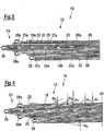
- Fig. 3 shows the rigid portion 12 of the stent 10 of FIG Fig. 1 and Fig. 2 in a so-called cutting representation.
- Fig. 3 thus shows a projection of cuts made in a raw material of the stent into a plane.
- a line thus indicates a section.
- Several staggered parallel straight sections can be used when expanding the stent 10 to the in Fig. 1 and Fig. 2 shown diamond-shaped cells 18 are expanded.
- Fig. 3 shows only the rigid portion 12 of the stent 10th
- Fig. 3 It can be seen that between the longest rhombic cells 18a elongated connecting portions 20a are provided, which lead to a more uniform bending of all diamond-shaped cells 18 during expansion of the stent.
- Fig. 4 shows the view from Fig. 3 with registered angles, which are formed by connecting portions 20 with a circumferential direction. Shown are six angles ⁇ 1 , ⁇ 2 , ⁇ 3 , ⁇ 4 , ⁇ 5 , ⁇ 6 , from an angle of about 22 ° ( ⁇ 1 ) over angles of about 40 ° ( ⁇ 2 ), 50 ° ( ⁇ 3 ), 62 ° ( ⁇ 4 ) and 65 ° ( ⁇ 5 ) increase steadily to an angle of approximately 71 ° ( ⁇ 6 ).
- a straight end line 30, which is arranged at the transition from the rigid region 12 to the flexible region 14, extends in the circumferential direction through connecting portions 20 and thus defines an angle of 0 °.
Landscapes
- Health & Medical Sciences (AREA)
- Engineering & Computer Science (AREA)
- Biomedical Technology (AREA)
- Heart & Thoracic Surgery (AREA)
- Life Sciences & Earth Sciences (AREA)
- Cardiology (AREA)
- Oral & Maxillofacial Surgery (AREA)
- Transplantation (AREA)
- Physics & Mathematics (AREA)
- Vascular Medicine (AREA)
- Optics & Photonics (AREA)
- Animal Behavior & Ethology (AREA)
- General Health & Medical Sciences (AREA)
- Public Health (AREA)
- Veterinary Medicine (AREA)
- Media Introduction/Drainage Providing Device (AREA)
- Prostheses (AREA)
- Materials For Medical Uses (AREA)
Description
Die vorliegende Erfindung betrifft ein Verfahren zur Herstellung eines Stents, etwa zur transluminalen Implantation in Hohlorgane, insbesondere in Blutgefäße, Harnleiter, Speiseröhren, Colon, Duodenum oder Gallenwege, mit einem im Wesentlichen röhrenförmigen Körper, der von einem komprimierten Zustand mit einem ersten Querschnittsdurchmesser in einen expandierten Zustand mit einem vergrößerten zweiten Querschnittsdurchmesser überführbar ist, wobei der Stent eine Vielzahl von Zellen umfasst, welche von durch den röhrenförmigen Körper gebildeten Umrandungselementen definiert werden.The present invention relates to a method for the production of a stent, such as for transluminal implantation in hollow organs, in particular in blood vessels, ureters, esophagus, colon, duodenum or biliary tract, having a substantially tubular body, which from a compressed state with a first cross-sectional diameter in one expanded state with an enlarged second cross-sectional diameter, wherein the stent comprises a plurality of cells, which are defined by bordering elements formed by the tubular body.
Stents dieser Art werden zur Rekanalisation von krankhaft veränderten Hohlorganen eingesetzt. Dabei werden die Stents im komprimierten Zustand über einen Einführkatheter an die zu behandelnde Stelle innerhalb des Hohlorgans eingeführt, wo sie durch unterschiedliche Maßnahmen auf einen Durchmesser, der dem Durchmesser des gesunden Hohlorgans entspricht, expandiert werden, so dass eine Stützwirkung des Hohlorgans, beispielsweise einer Gefäßwand, erreicht wird.Stents of this type are used for the recanalization of pathologically altered hollow organs. The stents are introduced in the compressed state via an insertion catheter to the treatment site within the hollow organ, where they are expanded by different measures to a diameter corresponding to the diameter of the healthy hollow organ, so that a supporting effect of the hollow organ, such as a vessel wall , is achieved.
Derartige Stents können zum Beispiel dadurch erzeugt werden, dass in die Wand eines röhrenförmigen Körpers Durchbrechungen wie zum Beispiel Schlitze geschnitten werden, die sich teilweise in Längsrichtung des Stents erstrecken, so dass bei der Expansion des Stents beispielsweise rautenförmige Durchbrechungen entstehen. Eine Durchbrechung zusammen mit ihren Umrandungselementen wird als Zelle bezeichnet.Such stents may be produced, for example, by cutting apertures in the wall of a tubular body, such as slits, which extend partially in the longitudinal direction of the stent such that, for example, diamond-shaped apertures arise during expansion of the stent. An opening along with its border elements is called a cell.
Werden Stents in der Nähe einer Bifurkation eines Hohlorgans eingesetzt, so können Stents verwendet werden, die ein abgeschrägtes Ende aufweisen. Solche Stents bieten die Möglichkeit, z.B. eine Vene allseitig bis zur Bifurkation abzustützen, d.h. beispielsweise bis zur Mündung in eine weitere Vene.When stents are used in the vicinity of a hollow organ bifurcation, stents may be used which have a bevelled end. Such stents offer the possibility, e.g. support a vein on all sides to the bifurcation, i. for example, to the mouth in another vein.
Um ihre Stützwirkung gewährleisten zu können, müssen die Stents in der Lage sein, eine ausreichende radiale Aufstellkraft auszuüben, die einer von der Gefäßwand ausgeübten radialen Krafteinwirkung entgegenwirkt. Dies gilt besonders im Bereich des abgeschrägten Endes, da dort die radiale Aufstellkraft üblicherweise reduziert ist.In order to be able to ensure their supporting effect, the stents must be able to exert a sufficient radial positioning force, which counteracts a force exerted by the vessel wall radial force. This is especially true in the area of the tapered end, since there the radial Aufstellkraft is usually reduced.
Die
Die
Die Aufgabe der Erfindung ist es, ein Verfahren zur Herstellung eines Stents anzugeben, das zu einem gleichmäßigen Aufdehnen von Zellen eines Stents führt. Angegeben wird hierfür ein Verfahren zur Herstellung eines Stents, bei welchem
- a) der Stent aus einem röhrenförmigen Material geschnitten wird und
- b) der Stent bis zu seinem expandierten Zustand aufgeweitet wird.
- a) the stent is cut from a tubular material and
- b) the stent is widened to its expanded state.
Es zeichnet sich dadurch aus, dass
- c) in dem expandierten Zustand die Form der Zellen des Stents geändert und fixiert wird.
- c) in the expanded state, the shape of the cells of the stent is changed and fixed.
Durch die Änderung der Form der Zellen können die einzelnen Zellen jeweils derart geformt werden, dass ein gleichmäßiges Aufdehnverhalten der einzelnen Zellen erreicht wird. Auf diese Weise kann die Bruchgefahr insbesondere bei kurzen und mittleren Zellen in der Nähe des abgeschrägten Bereichs reduziert werden, welche sich üblicherweise aufgrund einer inhomogenen Kraftverteilung beim Expandieren unsymmetrisch und übermäßig aufdehnen.By changing the shape of the cells, the individual cells can each be shaped so that a uniform Aufdehnverhalten the individual cells is achieved. In this way, the risk of breakage can be reduced, in particular in the case of short and medium cells in the vicinity of the beveled region, which usually expand asymmetrically and excessively due to an inhomogeneous force distribution during expansion.
Beispielsweise können bei rautenförmigen Zellen mit bis zu vier Verbindungsabschnitten an den jeweiligen Ecken der Raute die spitzen Winkel derart verringert oder verändert werden, dass diese kleiner als 70°, bevorzugt kleiner als 60°, sind. Dies führt dazu, dass der Stent großen äußeren Kräften im Bereich des abgeschrägten Bereichs durch eine homogene Kraftableitung über die Struktur besser standhalten kann und das Risiko eines Stentkollapses oder eines Stentbruchs deutlich verringert wird.For example, in diamond-shaped cells with up to four connecting sections at the respective corners of the rhombus, the acute angles can be reduced or changed so that they are smaller than 70 °, preferably smaller than 60 °. As a result, the stent can better withstand large external forces in the area of the beveled area by virtue of homogeneous force transmission across the structure and the risk of stent collapse or stent fracture is markedly reduced.
Mittels des Verfahrens ist es zudem möglich, ein zu weites Aufdehnen von Zellen zu verhindern, wodurch eine Vorschädigung von Verbindungsabschnitten vermieden werden kann.By means of the method, it is also possible to prevent too wide expansion of cells, whereby a pre-damage of connecting portions can be avoided.
Gemäß einer vorteilhaften Ausführungsform wird zum Aufweiten ein Kern verwendet, an welchem Befestigungsmittel angebracht werden, um die Form der Zellen des Stents zu ändern und zu fixieren. Mit den Befestigungsmitteln kann also das Aufdehnverhalten der einzelnen Zellen angepasst werden. Die Form der Zellen wird folglich gegenüber der Aufdehnung bei der reinen Verwendung z.B. eines zylinderförmigen Kerns verändert. Ein solcher zylinderförmiger Kern kann auch einen kegelförmigen Abschnitt umfassen, der das Aufziehen des Stents erleichtert. Zudem kann das Aufdehnen unter Wärmezuführung erfolgen.According to an advantageous embodiment, a core is used for expansion, to which attachment means are attached in order to change and fix the shape of the cells of the stent. With the fasteners so the Aufdehnverhalten the individual cells can be adjusted. The shape of the cells is thus changed from the expansion in the mere use of, for example, a cylindrical core. Such a cylindrical core may also include a tapered portion that facilitates the deployment of the stent. In addition, the expansion can be done with heat.
Besonders bevorzugt sind die Befestigungsmittel Nadeln oder Dorne, die in Löcher des Kerns eingebracht werden. Die Nadeln oder Dorne können beispielsweise von innen aus dem Kern herausgefahren oder von außen in den Kern eingesteckt werden. Hierzu kann beispielsweise ein automatisierter Prozess mittels Robotern oder einer Hydraulik aber auch eine manuelle Anpassung der Zellen durchgeführt werden.Particularly preferably, the fastening means are needles or mandrels which are introduced into holes of the core. For example, the needles or mandrels can be moved out of the core from the inside or inserted into the core from the outside. For this purpose, for example, an automated process by means of robots or hydraulics, but also a manual adaptation of the cells can be performed.
Gemäß einer weiteren vorteilhaften Ausführungsform wird die geänderte Form der Zellen des Stents mittels eines Wärmeprozesses dauerhaft fixiert. Eine solche Fixierung ist insbesondere bei der Verwendung von Memory-Metallen von Vorteil, die bei Temperaturerhöhung die durch den Wärmeprozess gespeicherte Form wieder einnehmen. Unter einer dauerhaften Fixierung ist eine Fixierung der Form der Zellen des Stent im expandierten Zustand des Stents zu verstehen, wobei die Form der Zellen im expandierten Zustand beibehalten wird, auch wenn der Stent zwischenzeitlich in den komprimierten Zustand überführt wird. Beim Einbringen des Stents in den Körper kann dann durch die Körperwärme der Stent und dessen Zellen die während des Herstellungsprozesses eingelernte Form wieder annehmen.According to a further advantageous embodiment, the altered shape of the cells of the stent is permanently fixed by means of a heating process. Such a fixation is particularly advantageous in the use of memory metals, which resume the stored by the heat process form when the temperature increases. A permanent fixation is understood to mean a fixation of the shape of the cells of the stent in the expanded state of the stent, wherein the shape of the cells is maintained in the expanded state, even if the stent is transferred in the meantime in the compressed state. When the stent is introduced into the body, the body heat then allows the stent and its cells to resume the form taught during the production process.
Im genannten Verfahren kann ein Stent verwendet werden, bei dem ein Teil der Zellen im Vergleich zu den übrigen Zellen in Längsrichtung des Stents verlängert ausgebildet ist, um ein abgeschrägtes stirnseitiges Ende des Stents zu bilden.In said method, a stent may be used in which a portion of the cells is elongated in the longitudinal direction of the stent compared to the remaining cells to form a bevelled end-face end of the stent.
Aufgrund der verlängerten Zellen kann ein abgeschrägtes Ende erzeugt werden. Dabei werden wegen der in Längsrichtung verlängerten Zellen keine zusätzlichen Zellen benötigt, um das abgeschrägte Ende zu bilden. Mittels der verlängerten Zellen wird es ermöglicht, auch in dem abgeschrägten Bereich eine ähnliche Anordnung der Zellen zu wählen, wie in dem übrigen röhrenförmigen Körper.Due to the elongated cells, a beveled end can be created. In this case, because of the longitudinally elongated cells, no additional cells are needed to form the bevelled end. By means of the elongated cells, it is possible to select a similar arrangement of the cells in the bevelled area as in the rest of the tubular body.
Die verlängerten Zellen können insbesondere nur in einem starren Abschnitt des Stents vorliegen. Zusätzlich kann der Stent z.B. einen flexiblen Abschnitt und/oder einen Verankerungsabschnitt umfassen. Die nachfolgenden Ausführungen bezüglich der verlängerten Zellen beziehen sich auf den starren Abschnitt.In particular, the elongated cells can only be present in a rigid section of the stent. In addition, the stent may e.g. a flexible section and / or anchoring section. The following remarks concerning the extended cells refer to the rigid section.
Durch die Vermeidung zusätzlicher Zellen ergibt sich eine Struktur des Stents, die eine besonders hohe radiale Aufstellkraft bereitstellen kann. Auf diese Weise wird es ermöglicht, beispielsweise Blutgefäße in der Nähe von Bifurkationen zuverlässig abzustützen. Ein erfindungsgemäßer Stent kann deshalb beispielsweise bei venösen Obstruktionen im Bereich der Bifurkation, dem Zusammenfluss der beiden Venae iliaca communis in die Vena cava inferior, im oberen Bereich der Vena iliaca communis eingesetzt werden. Der Stent kann dazu einen Durchmesser von größer oder gleich 12 mm aufweisen. Bevorzugt kann der Stent einen Durchmesser zwischen 12 mm und 18 mm besitzen.The avoidance of additional cells results in a structure of the stent, which can provide a particularly high radial erection force. In this way it is possible, for example, to reliably support blood vessels in the vicinity of bifurcations. A stent according to the invention can therefore be used, for example, in the case of venous obstructions in the region of the bifurcation, the confluence of the two common iliac veins into the inferior vena cava, in the upper region of the common iliac vein. The stent may have a diameter of greater than or equal to 12 mm. Preferably, the stent may have a diameter between 12 mm and 18 mm.
Weiterhin erlaubt es der Verzicht auf zusätzliche Zellen, den Winkel der Abschrägung variabel festzulegen, da dieser Winkel durch die relative Verlängerung der verlängerten Zellen festgelegt werden kann.Furthermore, the elimination of additional cells allows the angle of the bevel to be set variably since this angle can be determined by the relative lengthening of the elongated cells.
Generell erlaubt es der abgeschrägte Bereich, das Hohlorgan bis zur Bifurkation zuverlässig abzustützen, ohne jedoch z.B. wesentlich in die Blutbahn nach der Bifurkation hineinzuragen.In general, the bevelled area allows the hollow organ to be reliably supported up to the bifurcation, but without e.g. it is essential to place it in the bloodstream after the bifurcation.
Eine Zelle kann durch einen Verbindungsabschnitt oder mehrere Verbindungsabschnitte mit einer oder mehreren anderen Zellen verbunden sein. Unter der Länge einer Zelle kann der Abstand in Längsrichtung zwischen zwei Verbindungsabschnitten verstanden werden, wobei jeweils die Mitte des jeweiligen Verbindungsabschnitts zu berücksichtigen ist. Eine Zelle umfasst die genannte Aussparung sowie ihre jeweiligen Umrandungselemente, wobei die Verbindungsabschnitte zu den Umrandungselementen gehören.A cell may be connected to one or more other cells through one or more connection sections. The length of a cell may be understood to mean the distance in the longitudinal direction between two connecting sections, wherein in each case the center of the respective connecting section is to be taken into account. A cell comprises said recess and its respective bordering elements, the connecting sections belonging to the bordering elements.
Bei einem solchen Stent können die Zellen zumindest zum Teil jeweils mittels mehreren Verbindungsabschnitten miteinander verbunden sein. Insbesondere können in dem abgeschrägten Bereich und/oder bei den verlängerten Zellen jeweils drei oder vier Verbindungsabschnitte vorgesehen sein. Somit kann die Stützwirkung durch die auf diese Weise zu erreichende radiale Aufstellkraft besonders hoch sein.In such a stent, the cells can be connected to each other at least in part by means of a plurality of connecting sections. In particular, three or four connecting sections may be provided in each case in the bevelled area and / or in the case of the extended cells. Thus, the support effect can be particularly high by reaching in this way radial Aufstellkraft.
Der Stent kann aus einem Memory-Metall gefertigt sein, das ab einer Grenztemperatur eine gespeicherte Form einnimmt.The stent can be made of a memory metal, which assumes a stored form from a limit temperature.
Bevorzugte Ausführungsformen der Erfindung sind der Beschreibung, den Unteransprüchen und den Zeichnungen zu entnehmen.Preferred embodiments of the invention are described in the description, the subclaims and the drawings.
Zumindest ein Teil der verlängerten Zellen kann entlang einer geraden oder annähernd geraden Linie angeordnet, die insbesondere parallel oder annähernd parallel zu der Längsrichtung verläuft. Dies bedeutet, dass beispielsweise zumindest eine oder zwei auf der geraden Linie hintereinander angeordnete Zellen vorgesehen sein können. Bei mehr als zwei Zellen können zumindest zwei Verbindungsabschnitte zumindest einer dieser Zellen mit zwei weiteren der verlängerten Zellen direkt verbunden sein. Insbesondere liegen jeweils zwei Verbindungsabschnitte der verlängerten Zellen auf der geraden Linie.At least a portion of the elongate cells may be arranged along a straight or approximately straight line, in particular parallel or approximately parallel to the longitudinal direction. This means that, for example, at least one or two cells arranged one behind the other on the straight line can be provided. With more than two cells, at least two connecting sections of at least one of these cells can be directly connected to two further of the extended cells. In particular, each two connecting portions of the elongated cells lie on the straight line.
Die verlängerten Zellen können in mehrere Gruppen, insbesondere in neun Gruppen, einteilbar sein, wobei die Zellen jeder Gruppe jeweils entlang einer geraden oder annähernd geraden Linie angeordnet sind und diese Linien insbesondere parallel oder annähernd parallel zu der Längsrichtung verlaufen. Insgesamt können bei dem Stent zwölf Gruppen von Zellen vorgesehen sein, von welchen neun Gruppen verlängerte Zellen aufweisen. Bei einer solchen Definition von Gruppen können die Zwischenräume zwischen den Gruppen selbst auch Zellen bilden.The elongate cells may be divisible into a plurality of groups, in particular into nine groups, the cells of each group being arranged along a straight or approximately straight line, respectively, and these lines being in particular parallel or approximately parallel to the longitudinal direction. In total, the stent may have twelve groups of cells, nine of which have extended cells. In such a definition of groups, the spaces between the groups themselves may also form cells.
Die Anordnung der Zellen kann also derart gewählt sein, dass die jeweiligen Zellen entlang von geraden oder annähernd geraden Linien angeordnet sind. Zusätzlich können die Zellen symmetrisch zu einer dieser Linien ausgebildet sein. Es können also insbesondere keine Zellen vorliegen, die geneigt bzw. gedreht zu den übrigen Zellen sind. Auf diese Weise kann eine Schwächung der Struktur durch solche gedrehten Zellen vermieden werden.The arrangement of the cells can thus be chosen such that the respective cells are arranged along straight or approximately straight lines. In addition, the cells may be symmetrical to one of these lines. In particular, therefore, there can be no cells which are inclined or rotated relative to the remaining cells. In this way, weakening of the structure by such rotated cells can be avoided.
Insbesondere können alle Zellen innerhalb einer Gruppe in Längsrichtung gesehen jeweils die gleiche oder die annähernd gleiche Länge aufweisen. Alternativ können in einer Gruppe auch Zellen mit unterschiedlichen Längen vorgesehen sein.In particular, all cells within a group viewed in the longitudinal direction may each have the same or approximately the same length. Alternatively, cells of different lengths may also be provided in a group.
Die Linien, welche durch die Zellen verschiedener Gruppen gebildet werden, können parallel oder annähernd parallel zueinander verlaufen.The lines formed by the cells of different groups may be parallel or approximately parallel to each other.
Von einer sich senkrecht zur Längsachse erstreckenden Querschnittsebene bis zu dem abgeschrägten stirnseitigen Ende können jeweils gleich viele Zellen in jeder Gruppe vorgesehen sein. Durch die Vorsehung jeweils gleich vieler Zellen in einer Gruppe kann eine radiale Aufstellkraft bewirkt werden, welche über die Länge des Stents im Wesentlichen konstant ist. Bevorzugt können in dem starren Abschnitt des Stents in jeder Gruppe gleich viele Zellen vorgesehen sein.From a cross-sectional plane extending perpendicularly to the longitudinal axis up to the bevelled end-side end, in each case the same number of cells can be provided in each group. By providing respectively the same number of cells in a group, a radial setting-up force can be effected, which is essentially constant over the length of the stent. Preferably, the same number of cells can be provided in the rigid section of the stent in each group.
Insbesondere bei der Verwendung gleich vieler Zellen können von den Verbindungsabschnitten der Zellen jeweils Winkel gebildet werden, die in der sogenannten Abwicklung des Stents zu erkennen sind. Die Winkel werden durch die Umfangsrichtung (welche in der Abwicklung eine Gerade ist) und eine gerade Linie definiert, wobei die gerade Linie durch Verbindungsabschnitte der Zellen verläuft. Dies bedeutet, dass die Verbindungsabschnitte jeweils zumindest eines Teils der Zellen in der Abwicklung auf geraden Linien liegen. Die Winkel können umso größer sein, je näher der Winkel dem abgeschrägten Ende des Stents ist, wobei bevorzugt vier, fünf oder sechs Winkel vorgesehen sind.In particular, when using the same number of cells can be formed by the connecting portions of the cells each angle, which can be seen in the so-called development of the stent. The angles are defined by the circumferential direction (which in the settlement is a straight line) and a straight line, the straight line passing through connecting sections of the cells. This means that the connection sections of at least a part of the cells in the development lie on straight lines. The angles can be bigger The closer the angle is to the beveled end of the stent, four, five or six angles are preferred.
An dem abgeschrägten Ende selbst können die Enden der Zellen in der Abwicklung keine gerade Linie bilden, sondern eine Kurve definieren, welche einer Sinus-Kurve angenähert ist. Eine solche Sinus-Kurve in der Abwicklung führt am dreidimensionalen Stent zu einem schrägen Anschnitt (dem abgeschrägten Bereich) mit einer exakt ebenen Schnittfläche.At the bevelled end itself, the ends of the cells in the development can not form a straight line, but define a curve which approximates a sine curve. Such a sinusoidal curve in the development leads on the three-dimensional stent to an oblique incision (the chamfered area) with an exactly flat cut surface.
Die Zellen können so angeordnet sein, dass ein erster Winkel in einem Bereich zwischen 20° und 24°, ein zweiter Winkel in einem Bereich zwischen 37° und 44°, ein dritter Winkel in einem Bereich zwischen 48° und 52°, ein vierter Winkel in einem Bereich zwischen 60° und 64°, ein fünfter Winkel in einem Bereich zwischen 63° und 67° und ein sechster Winkel in einem Bereich zwischen 69° und 73° liegt. Der größte Winkel kann insbesondere am nächsten an dem abgeschrägten Ende des Stents liegen, wohingegen der kleinste Winkel am weitesten entfernt von dem abgeschrägten Ende liegt. Zudem kann ein Winkel von 0° vorgesehen sein, dies bedeutet, dass eine Position an dem Stent in der Abwicklung existiert, an welcher Verbindungsabschnitte entlang der Umfangsrichtung angeordnet sind. Der Winkel von 0° kann an einem Übergang von dem starren Bereich zu dem flexiblen Bereich vorgesehen sein. Die Zellen einer Gruppe können unterschiedlich lang ausgeführt sein, um die beschriebenen Winkel zu bilden.The cells may be arranged so that a first angle in a range between 20 ° and 24 °, a second angle in a range between 37 ° and 44 °, a third angle in a range between 48 ° and 52 °, a fourth angle in a range between 60 ° and 64 °, a fifth angle in a range between 63 ° and 67 ° and a sixth angle in a range between 69 ° and 73 °. In particular, the greatest angle may be closest to the beveled end of the stent, whereas the smallest angle is farthest from the bevelled end. In addition, an angle of 0 ° may be provided, that is, a position exists on the stent in the unwinding, on which connecting portions are arranged along the circumferential direction. The angle of 0 ° may be provided at a transition from the rigid area to the flexible area. The cells of a group may be of different lengths to form the described angles.
Für eine derartige Auswahl der Winkel hat es sich gezeigt, dass auf diese Weise ein sehr stabiler Stent geschaffen werden kann, der eine besonders lange Haltbarkeit aufweist.For such a selection of the angle, it has been found that in this way a very stable stent can be created, which has a particularly long durability.
Die Länge der Zellen benachbarter Gruppen in Umfangsrichtung kann von einem Maximum bis zu einem Minimum fallen. Insbesondere liegen Zellen mit maximaler Länge Zellen mit minimaler Länge bezüglich einer zentralen Achse des Stents gegenüber. Durch eine derartige Anordnung kann die Abschrägung erzeugt werden.The length of the cells of adjacent groups in the circumferential direction may fall from a maximum to a minimum. In particular, cells are at maximum Length cells of minimal length with respect to a central axis of the stent opposite. By such an arrangement, the bevel can be generated.
Die Zellen können zumindest zum Teil mittels Verbindungsabschnitten miteinander verbunden sein, wobei die Verbindungsabschnitte zwischen den verlängerten Zellen, insbesondere nur zwischen den längsten Zellen, verlängert ausgebildet sind. Aufgrund der verlängerten bzw. vergrößerten Verbindungsabschnitte können die Öffnungen der längsten Zellen verkürzt werden, wodurch beim Expandieren des Stents ein gleichmäßiges Aufbiegen sämtlicher Zellen erreicht werden kann. Ein derart gleichmäßiges Aufbiegen kann wiederum zu einer gleichmäßigen Verteilung der radialen Aufstellkraft sowie zu einem besonders robusten Stent führen.The cells may be connected to one another at least in part by means of connecting sections, wherein the connecting sections between the extended cells, in particular only between the longest cells, are formed extended. Due to the enlarged or enlarged connecting portions, the openings of the longest cells can be shortened, whereby a uniform bending of all cells can be achieved during expansion of the stent. Such a uniform bending in turn can lead to a uniform distribution of the radial erection force and to a particularly robust stent.
Es kann sich in Längsrichtung von dem abgeschrägten Ende zumindest ein Marker weg erstrecken, insbesondere in Form einer Öse, wobei der Marker eine asymmetrische Form aufweist. Ein Marker kann ein Abschnitt des Stents sein, der eine erhöhte Röntgendichtigkeit aufweist, d.h. in einem Röntgenbild besonders gut sichtbar ist. Insbesondere kann es sich bei dem Marker um eine Öse handeln, die beispielsweise mit Tantal gefüllt oder bedeckt ist. Aufgrund der asymmetrischen Form kann der Marker auch in dem abgeschrägten Bereich angebracht sein, da sich der Marker von der Abschrägung weg erstrecken kann.At least one marker may extend longitudinally from the bevelled end, in particular in the form of an eyelet, the marker having an asymmetrical shape. A marker may be a portion of the stent having increased radiopacity, i. is particularly visible in an X-ray image. In particular, the marker may be an eyelet filled or covered, for example, with tantalum. Because of the asymmetrical shape, the marker can also be mounted in the bevelled area because the marker can extend away from the taper.
Anders ausgedrückt kann der Marker also in einem Bereich zwischen der längsten und der kürzesten Erstreckung des Stents in Längsrichtung angeordnet sein. Aufgrund der asymmetrischen Form kann der Marker groß genug ausgeführt werden, um besonders gut im Röntgenbild erkannt zu werden. Zusätzlich kann ein weiterer Marker z.B. an der Spitze der Abschrägung vorgesehen sein. Noch ein weiterer Marker kann beispielsweise an einer kürzesten Stelle des Stents an der Abschrägung angebracht sein.In other words, the marker can thus be arranged in a region between the longest and the shortest extent of the stent in the longitudinal direction. Due to the asymmetrical shape of the marker can be made large enough to be particularly well recognized in the X-ray image. In addition, another marker may be provided, for example, at the top of the chamfer. Yet another marker may, for example, be attached to the chamfer at a shortest point of the stent.
Es können zumindest zwei asymmetrische Marker an dem abgeschrägten Ende vorgesehen sein, wobei sich die Marker bezüglich einer Achse des Stents insbesondere gegenüberliegen. Die beiden Marker können also symmetrisch zu einer Ebene des Stents liegen, welche durch eine Achse des Stents und eine Spitze der Abschrägung verläuft. Aufgrund einer solchen Anordnung können die asymmetrischen Marker in einem Röntgenbild beispielsweise zur Deckung gebracht werden. In der Folge kann die Lage des Stents im Röntgenbild besonders gut zu erkennen sein.At least two asymmetrical markers may be provided at the beveled end, with the markers in particular facing one another with respect to an axis of the stent. Thus, the two markers may be symmetrical about a plane of the stent which passes through an axis of the stent and a peak of the chamfer. Due to such an arrangement, the asymmetrical markers can be brought into coincidence in an X-ray image, for example. As a consequence, the position of the stent in the x-ray image can be particularly well recognized.
Der Stent kann einen flexiblen Abschnitt umfassen, der sich an den starren Abschnitt anschließt. Der flexible Abschnitt liegt dem abgeschrägten Ende gegenüber. Der flexible Abschnitt kann Zellen aufweisen, welche in der Abwicklung eine größere Fläche aufweisen als Zellen des starren Abschnitts. Aufgrund der größeren Zellen kann der flexible Abschnitt leichter biegbar sein, wodurch sich der flexible Abschnitt auf einfache Weise an die Verlaufsform eines Hohlorgans anpassen kann. Bevorzugt können die Zellen des flexiblen Abschnitts eine zahnförmige Begrenzung aufweisen.The stent may include a flexible portion that connects to the rigid portion. The flexible portion is opposite the tapered end. The flexible portion may have cells which have a larger area in the development than cells of the rigid portion. Due to the larger cells, the flexible portion can be more easily bendable, whereby the flexible portion can easily adapt to the shape of a hollow organ. Preferably, the cells of the flexible portion may have a tooth-shaped boundary.
Der Stent kann einen Verankerungsabschnitt umfassen, der sich an den flexiblen Abschnitt anschließt. Die Zellen des Verankerungsabschnitts können den Zellen des starren Abschnitts entsprechen und beispielsweise rautenförmig ausgebildet sein. Der Verankerungsabschnitt kann aufgrund der rautenförmigen Zellen eine geringe Flexibilität aufweisen und so den Stent an seiner Position in dem Hohlorgan fixieren. Der Verankerungsabschnitt kann ein gerades Ende des Stents bilden, an welchem Marker angebracht sein können, die sich von einem Ende des Stents weg erstrecken. Die Marker können die Form von Ösen haben und ebenfalls z.B. mit Tantal bedeckt oder gefüllt sein. Beim Einführen des Stents in das Hohlorgan kann der Stent mittels der Marker des Verankerungsabschnitts in einem Einführkatheter fixiert werden.The stent may include an anchoring portion that adjoins the flexible portion. The cells of the anchoring portion may correspond to the cells of the rigid portion and may be diamond-shaped, for example. The anchoring portion may have a low flexibility due to the rhombic cells and thus fix the stent in position in the hollow organ. The anchoring portion may form a straight end of the stent to which markers may be attached extending from one end of the stent. The markers may have the form of eyelets and may also be covered or filled with tantalum, for example. When inserting the stent into the hollow organ, the stent can be fixed by means of the markers of the anchoring section in an insertion catheter.
Nachfolgend wird die Erfindung anhand vorteilhafter Ausführungsformen unter Bezugnahme auf die beigefügten Zeichnungen beschrieben. Es zeigen:
- Fig. 1
- einen erfindungsgemäßen Stent im expandierten Zustand in Seitenansicht;
- Fig. 2
- den Stent von
Figur 1 im expandierten Zustand in einer Draufsicht; - Fig. 3
- den Stent von
Figur 1 in einer in eine Ebene projizierten Schneiddarstellung; und - Fig. 4
- die Schneiddarstellung von
Fig. 3 mit einer Darstellung von Winkeln, welche durch Verbindungsabschnitte definiert werden.
- Fig. 1
- a stent according to the invention in the expanded state in side view;
- Fig. 2
- the stent of
FIG. 1 in the expanded state in a plan view; - Fig. 3
- the stent of
FIG. 1 in an in-plane projected cutting representation; and - Fig. 4
- the cutting representation of
Fig. 3 with a representation of angles which are defined by connecting sections.
Der starre Abschnitt 12 ist aus rautenförmigen (geschlossenen) Zellen 18 gebildet, welche jeweils über drei oder vier Verbindungsabschnitte 20 mit anderen rautenförmigen Zellen 18 verbunden sind. Die rautenförmigen Zellen 18 werden durch stegartige Umrandungselemente 22 definiert, die aus einem Metall geformt sind.The
Der starre Abschnitt 12 umfasst einen abgeschrägten Bereich 24, welcher den Einsatz des Stents 10 an einer (nicht gezeigten) Bifurkation eines Hohlorgans ermöglicht.The
Der abgeschrägte Bereich 24 bildet ein Ende des Stents 10 und wird erzeugt, indem ein Teil der rautenförmigen Zellen 18 in einer Längsrichtung L verlängert ausgebildet ist. Die längsten rautenförmigen Zellen 18 sind in den Figuren mit dem Bezugszeichen 18a gekennzeichnet, wohingegen die kürzesten rautenförmigen Zellen 18 mit dem Bezugszeichen 18b gekennzeichnet sind. In dem starren Abschnitt 12 sind jeweils drei der kürzesten rautenförmigen Zellen 18b und drei der längsten rautenförmigen Zellen 18a in Längsrichtung L vorgesehen. Die längsten rautenförmigen Zellen 18a liegen dabei den kürzen rautenförmigen Zellen 18b bezüglich einer zentralen Achse des Stents 10 gegenüber. Es sind jeweils drei Gruppen der längsten und der kürzesten rautenförmigen Zellen 18a, 18b nebeneinander (d.h. in Umfangsrichtung benachbart) vorgesehen.The chamfered
In dem flexiblen Abschnitt 14 sind offene Zellen 26 mit gezacktem bzw. zahnförmigem Umriss angeordnet, wobei in Umfangsrichtung des Stents 10 gesehen jeweils weniger offene gezackte Zellen 26 vorgesehen sind als rautenförmige Zellen 18. Durch die Verwendung weniger offener gezackter Zellen 26 ist der flexible Abschnitt leichter bezüglich der Längsrichtung L verformbar und kann sich so dem Verlauf einer Blutbahn oder ähnlichem gut anpassen.In the
Der Verankerungsabschnitt 16 ist durch rautenförmige Zellen 18 gebildet, die für eine erhöhte Steifigkeit des Verankerungsabschnitts 16 sorgen, wodurch der Stent 10 seine Position in einem Hohlorgan zuverlässig beibehält.The anchoring
Sowohl an dem abgeschrägten Bereich 24 als auch an dem durch den Verankerungsabschnitt gebildeten Ende des Stents 10 sind jeweils vier ösenförmige Marker 28 vorgesehen, von welchen in
Zwei der Marker 28, welche in dem abgeschrägten Bereich 24 an den Stellen der längsten und der kürzesten Erstreckung des Stents 10 angebracht sind, sind symmetrisch ausgebildet. Zwei weitere Marker 28 sind dort an dem abgeschrägten Bereich 24 angebracht, wo der Stent 10 seine durchschnittliche Länge aufweist. Diese beiden Marker 28 sind als asymmetrische Marker 28a ausgebildet, wobei sich die Fläche der asymmetrischen Marker 28a zu der kürzesten Erstreckung des Stents hin erstreckt.Two of the
Die als weiße Bereiche dargestellten, zwischen den Linien vorhandenen Materialbereiche werden nach dem Expandieren zu Verbindungsabschnitten 20 oder Umrandungselementen 22.
In
- 1010
- Stentstent
- 1212
- starrer Abschnittrigid section
- 1414
- flexibler Abschnittflexible section
- 1616
- Verankerungsabschnittanchoring section
- 18, 18a, 18b18, 18a, 18b
- rautenförmige Zellediamond-shaped cell
- 20, 20a20, 20a
- Verbindungsabschnittconnecting portion
- 2222
- Umrandungselementborder element
- 2424
- abgeschrägter Bereichbevelled area
- 2626
- offene gezackte Zelleopen jagged cell
- 28, 28a28, 28a
- Markermarker
- 3030
- Endlinieendline
- LL
- Längsrichtunglongitudinal direction
- αα
- Winkelcorner
Claims (5)
- A method of manufacturing a stent (10), in whicha) the stent (10) is cut out of a tubular material;b) the stent (10) is widened up to its expanded state,characterized in thatc) the shape of the cells (18, 18a, 18b) of the stent (10) is changed and fixed in the expanded state.
- A method in accordance with claim 1,
characterized in that a core is used for the widening to which fastening means are attached to change and to fix the shape of the cells (18, 18a, 18b) of the stent (10). - A method in accordance with claim 1 or claim 2,
characterized in that
the fastening means are needles or mandrels that are introduced into holes of the core. - A method in accordance with claim 2 or claim 3,
characterized in that
the changed shape of the cells (18, 18a, 18b) of the stent (10) is permanently fixed by means of a heating process. - A method in accordance with any one of the preceding claims, in which a stent (10) for transluminal implantation into hollow organs, in particular into blood vessels, ureters, esophagi, the colon, the duodenum or the biliary tract is used having a substantially tubular body which can be converted from a compressed state having a first cross-sectional diameter into an expanded state having an enlarged second cross-sectional diameter, wherein the stent (10) comprises a plurality of cells (18, 18a, 18b) which are defined by bordering elements (22) formed by the tubular body, and wherein some of the cells (18, 18a) are formed as elongated in the longitudinal direction of the stent (10) in comparison with the other cells (18b) to form a chamfered front face end (24) of the stent (10).
Priority Applications (2)
| Application Number | Priority Date | Filing Date | Title |
|---|---|---|---|
| ES18185569T ES2758705T5 (en) | 2015-07-23 | 2015-07-23 | Procedure for the manufacture of a stent |
| EP18185569.3A EP3415122B2 (en) | 2015-07-23 | 2015-07-23 | Method for producing a stent |
Applications Claiming Priority (3)
| Application Number | Priority Date | Filing Date | Title |
|---|---|---|---|
| EP15742005.0A EP3302372B1 (en) | 2015-07-23 | 2015-07-23 | Stent |
| PCT/EP2015/066895 WO2017012673A1 (en) | 2015-07-23 | 2015-07-23 | Stent |
| EP18185569.3A EP3415122B2 (en) | 2015-07-23 | 2015-07-23 | Method for producing a stent |
Related Parent Applications (2)
| Application Number | Title | Priority Date | Filing Date |
|---|---|---|---|
| EP15742005.0A Division EP3302372B1 (en) | 2015-07-23 | 2015-07-23 | Stent |
| EP15742005.0A Division-Into EP3302372B1 (en) | 2015-07-23 | 2015-07-23 | Stent |
Publications (3)
| Publication Number | Publication Date |
|---|---|
| EP3415122A1 EP3415122A1 (en) | 2018-12-19 |
| EP3415122B1 true EP3415122B1 (en) | 2019-09-11 |
| EP3415122B2 EP3415122B2 (en) | 2022-09-28 |
Family
ID=53724356
Family Applications (2)
| Application Number | Title | Priority Date | Filing Date |
|---|---|---|---|
| EP18185569.3A Active EP3415122B2 (en) | 2015-07-23 | 2015-07-23 | Method for producing a stent |
| EP15742005.0A Active EP3302372B1 (en) | 2015-07-23 | 2015-07-23 | Stent |
Family Applications After (1)
| Application Number | Title | Priority Date | Filing Date |
|---|---|---|---|
| EP15742005.0A Active EP3302372B1 (en) | 2015-07-23 | 2015-07-23 | Stent |
Country Status (11)
| Country | Link |
|---|---|
| US (2) | US10507125B2 (en) |
| EP (2) | EP3415122B2 (en) |
| JP (1) | JP6622914B2 (en) |
| CN (1) | CN108472147B (en) |
| AU (2) | AU2015402709B2 (en) |
| BR (1) | BR112018001386B1 (en) |
| CA (1) | CA2993286A1 (en) |
| ES (2) | ES2758705T5 (en) |
| HK (1) | HK1250325B (en) |
| SI (1) | SI3302372T1 (en) |
| WO (1) | WO2017012673A1 (en) |
Families Citing this family (20)
| Publication number | Priority date | Publication date | Assignee | Title |
|---|---|---|---|---|
| CN108472147B (en) | 2015-07-23 | 2023-06-20 | 奥普特米德医疗器械股份有限公司 | Support frame |
| EP3649991B1 (en) * | 2017-07-07 | 2022-03-02 | Kaneka Corporation | Tubular medical tool and tubular medical tool transfer device |
| CN107714244A (en) * | 2017-10-26 | 2018-02-23 | 柏为(武汉)医疗科技股份有限公司 | Vein blood vessel is from swollen support |
| CN108938160B (en) * | 2017-11-17 | 2024-07-12 | 杭州唯强医疗科技有限公司 | Stent for near bifurcation lesions |
| CN109793600B (en) * | 2017-11-17 | 2024-09-13 | 杭州唯强医疗科技有限公司 | Bracket for lesions at near bifurcation part |
| WO2019096158A1 (en) | 2017-11-17 | 2019-05-23 | 杭州唯强医疗科技有限公司 | Endovascular stent |
| CN110721012A (en) * | 2018-07-16 | 2020-01-24 | 杭州唯强医疗科技有限公司 | Marking support for subsection |
| CN110721013A (en) * | 2018-07-16 | 2020-01-24 | 杭州唯强医疗科技有限公司 | Naked support of sectional type |
| EP3738554A1 (en) | 2019-05-15 | 2020-11-18 | Roman Müller | Stent for implantation into a blood vessel of a patient |
| DE102019112971A1 (en) * | 2019-05-16 | 2020-11-19 | Optimed Medizinische Instrumente Gmbh | STENT |
| CN110368158A (en) * | 2019-08-22 | 2019-10-25 | 浙江归创医疗器械有限公司 | A kind of inclined opening structure shape intravascular stent |
| US12064343B2 (en) | 2020-03-04 | 2024-08-20 | Medtronic, Inc. | Devices and methods for multi-alignment of implantable medical devices |
| JP7299191B2 (en) * | 2020-03-31 | 2023-06-27 | 大塚メディカルデバイス株式会社 | Stents and catheter-stent systems |
| US20220061985A1 (en) * | 2020-08-25 | 2022-03-03 | Medtronic, Inc. | Devices and methods for multi-alignment of implantable medical devices |
| CN112022461B (en) * | 2020-09-16 | 2023-11-24 | 北京美迪微科技有限责任公司 | Be applied to vascular support of carotid artery |
| CN112043476A (en) * | 2020-09-29 | 2020-12-08 | 浙江归创医疗器械有限公司 | Bevel bracket |
| US20220126012A1 (en) * | 2020-10-28 | 2022-04-28 | Medtronic, Inc. | Medical implants for enhancing the healing response and the effective longevity of blood vessels and anastomoses and methods of use thereof |
| US11969343B2 (en) | 2020-12-07 | 2024-04-30 | Medtronic, Inc. | Transcatheter heart valve prosthesis systems and methods for rotational alignment |
| CN113888690B (en) * | 2021-10-19 | 2022-08-12 | 柏意慧心(杭州)网络科技有限公司 | Method, apparatus and medium for determining a target segment in a blood vessel |
| CN115381591B (en) * | 2022-08-01 | 2023-07-25 | 上海玮琅医疗科技有限公司 | Straight-cylinder type superior vena cava bracket |
Citations (5)
| Publication number | Priority date | Publication date | Assignee | Title |
|---|---|---|---|---|
| US6279368B1 (en) | 2000-06-07 | 2001-08-28 | Endovascular Technologies, Inc. | Nitinol frame heating and setting mandrel |
| US20030023299A1 (en) | 2000-03-27 | 2003-01-30 | Aga Medical Corporation | Repositionable and recapturable vascular stent/graft |
| US7112055B1 (en) | 2002-07-02 | 2006-09-26 | Endovascular Technologies, Inc. | Nitinol frame heating and setting mandrel |
| US20140277377A1 (en) | 2013-03-14 | 2014-09-18 | Thomas Ischinger | Oblique stent |
| WO2017012673A1 (en) | 2015-07-23 | 2017-01-26 | Variomed Ag | Stent |
Family Cites Families (21)
| Publication number | Priority date | Publication date | Assignee | Title |
|---|---|---|---|---|
| FR2737969B1 (en) * | 1995-08-24 | 1998-01-30 | Rieu Regis | INTRALUMINAL ENDOPROSTHESIS IN PARTICULAR FOR ANGIOPLASTY |
| JP4292710B2 (en) * | 1997-09-24 | 2009-07-08 | エム イー ディ インスチィチュート インク | Radially expandable stent |
| EP1164968A1 (en) | 1999-03-30 | 2002-01-02 | Angiolink Corporation | Angular vascular stent |
| US8080048B2 (en) * | 2001-12-03 | 2011-12-20 | Xtent, Inc. | Stent delivery for bifurcated vessels |
| US6969402B2 (en) * | 2002-07-26 | 2005-11-29 | Syntheon, Llc | Helical stent having flexible transition zone |
| US6878162B2 (en) | 2002-08-30 | 2005-04-12 | Edwards Lifesciences Ag | Helical stent having improved flexibility and expandability |
| US8562666B2 (en) * | 2005-09-28 | 2013-10-22 | Nitinol Development Corporation | Intraluminal medical device with nested interlocking segments |
| US20070266542A1 (en) | 2006-05-08 | 2007-11-22 | Cook Incorporated | Radiopaque marker for intraluminal medical device |
| US7988723B2 (en) | 2007-08-02 | 2011-08-02 | Flexible Stenting Solutions, Inc. | Flexible stent |
| US8734502B2 (en) | 2008-12-17 | 2014-05-27 | Cook Medical Technologies Llc | Tapered stent and flexible prosthesis |
| JP5401148B2 (en) * | 2009-03-31 | 2014-01-29 | テルモ株式会社 | In vivo indwelling stent and biological organ dilator |
| CN102458304B (en) | 2009-05-14 | 2016-07-06 | 奥巴斯尼茨医学公司 | There is the self-expandable stent of polygon transition region |
| CN102068331B (en) * | 2010-04-20 | 2013-08-07 | 上海微创医疗器械(集团)有限公司 | Bifurcate blood vessel stent |
| WO2011159342A1 (en) * | 2010-06-17 | 2011-12-22 | St. Jude Medical, Inc. | Collapsible heart valve with angled frame |
| US20130204391A1 (en) * | 2010-07-15 | 2013-08-08 | Tohoku Univresity | Highly elastic stent and production method for highly elastic stent |
| EP2415823B1 (en) | 2010-07-30 | 2012-10-03 | Nexans | Networkable polymer mixture for covers of cables and conduits |
| US9839540B2 (en) * | 2011-01-14 | 2017-12-12 | W. L. Gore & Associates, Inc. | Stent |
| US9028540B2 (en) * | 2011-03-25 | 2015-05-12 | Covidien Lp | Vascular stent with improved vessel wall apposition |
| US10548749B2 (en) * | 2013-06-20 | 2020-02-04 | Biiosensors International Group, Ltd. | Vascular stent with a mixed configuration of connectors |
| JP5695259B1 (en) | 2014-02-19 | 2015-04-01 | 株式会社World Medish | High flexibility stent |
| EP3206963A1 (en) | 2014-10-13 | 2017-08-23 | Bevaswiss AG | Rotary closure with internal, separately fillable capsule comprising film seal to be opened by means of rotation |
-
2015
- 2015-07-23 CN CN201580081865.8A patent/CN108472147B/en active Active
- 2015-07-23 ES ES18185569T patent/ES2758705T5/en active Active
- 2015-07-23 BR BR112018001386-2A patent/BR112018001386B1/en active IP Right Grant
- 2015-07-23 CA CA2993286A patent/CA2993286A1/en not_active Abandoned
- 2015-07-23 EP EP18185569.3A patent/EP3415122B2/en active Active
- 2015-07-23 SI SI201530841T patent/SI3302372T1/en unknown
- 2015-07-23 ES ES15742005T patent/ES2733491T3/en active Active
- 2015-07-23 WO PCT/EP2015/066895 patent/WO2017012673A1/en active Application Filing
- 2015-07-23 EP EP15742005.0A patent/EP3302372B1/en active Active
- 2015-07-23 JP JP2018522848A patent/JP6622914B2/en active Active
- 2015-07-23 US US15/746,652 patent/US10507125B2/en active Active
- 2015-07-23 AU AU2015402709A patent/AU2015402709B2/en active Active
-
2018
- 2018-07-04 HK HK18108663.9A patent/HK1250325B/en unknown
-
2019
- 2019-11-26 US US16/696,069 patent/US20200093620A1/en active Pending
-
2021
- 2021-02-22 AU AU2021201133A patent/AU2021201133B2/en active Active
Patent Citations (6)
| Publication number | Priority date | Publication date | Assignee | Title |
|---|---|---|---|---|
| US20030023299A1 (en) | 2000-03-27 | 2003-01-30 | Aga Medical Corporation | Repositionable and recapturable vascular stent/graft |
| US6279368B1 (en) | 2000-06-07 | 2001-08-28 | Endovascular Technologies, Inc. | Nitinol frame heating and setting mandrel |
| US7112055B1 (en) | 2002-07-02 | 2006-09-26 | Endovascular Technologies, Inc. | Nitinol frame heating and setting mandrel |
| US20140277377A1 (en) | 2013-03-14 | 2014-09-18 | Thomas Ischinger | Oblique stent |
| WO2017012673A1 (en) | 2015-07-23 | 2017-01-26 | Variomed Ag | Stent |
| EP3302372A1 (en) | 2015-07-23 | 2018-04-11 | optimed medizinische Instrumente GmbH | Stent |
Also Published As
| Publication number | Publication date |
|---|---|
| ES2758705T5 (en) | 2022-11-16 |
| AU2015402709B2 (en) | 2020-11-26 |
| JP6622914B2 (en) | 2019-12-18 |
| US20200093620A1 (en) | 2020-03-26 |
| SI3302372T1 (en) | 2019-09-30 |
| CN108472147B (en) | 2023-06-20 |
| EP3415122A1 (en) | 2018-12-19 |
| ES2733491T3 (en) | 2019-11-29 |
| AU2021201133A1 (en) | 2021-03-11 |
| CA2993286A1 (en) | 2017-01-26 |
| EP3302372B1 (en) | 2019-04-24 |
| EP3415122B2 (en) | 2022-09-28 |
| US20180221181A1 (en) | 2018-08-09 |
| BR112018001386A2 (en) | 2018-09-11 |
| HK1250325B (en) | 2019-12-13 |
| US10507125B2 (en) | 2019-12-17 |
| ES2758705T3 (en) | 2020-05-06 |
| JP2018525189A (en) | 2018-09-06 |
| EP3302372A1 (en) | 2018-04-11 |
| AU2015402709A1 (en) | 2018-02-15 |
| BR112018001386B1 (en) | 2022-06-28 |
| CN108472147A (en) | 2018-08-31 |
| AU2021201133B2 (en) | 2023-04-13 |
| WO2017012673A1 (en) | 2017-01-26 |
Similar Documents
| Publication | Publication Date | Title |
|---|---|---|
| EP3415122B1 (en) | Method for producing a stent | |
| DE69727004T2 (en) | A stent for angioplasty | |
| EP2475335B1 (en) | Medical implant | |
| DE102005016103B4 (en) | Duodenumstent | |
| DE69924706T2 (en) | STENT | |
| DE69632390T2 (en) | Implantable vascular and endoluminal stents | |
| DE69732992T2 (en) | Stent with variable properties for support optimization | |
| DE102007019772B4 (en) | Stent and method of making a stent | |
| EP3405146B1 (en) | Stent for using in bifurcations | |
| EP0801933A1 (en) | Stent for intraluminal placement in hollow organs | |
| EP2991593B1 (en) | Medical device for inserting into a hollow organ of the body | |
| EP2628468B1 (en) | Medical device | |
| DE102009060280B4 (en) | Medical implant and method of making such an implant | |
| DE69917739T2 (en) | EXPANDABLE STENT | |
| EP2675403B1 (en) | Medical device comprising an expandable lattice mesh | |
| WO2011107243A1 (en) | Radially expandable stent | |
| EP2895117B1 (en) | Stent | |
| DE102006017028A1 (en) | Self-expanding stent with spring structure | |
| DE19749691A1 (en) | Intraluminal element, especially coronary element | |
| WO2016059026A1 (en) | Stent for percutaneous vertebroplasty | |
| DE102015122678A1 (en) | Medical implant | |
| DE102013113271A1 (en) | Medical implant, treatment system with such an implant and method for producing an implant | |
| EP4417167A1 (en) | Medical device and treatment system | |
| DE19653708A1 (en) | Device for intralumenal implantation to expand blood vessel | |
| DE19653718C2 (en) | Stent |
Legal Events
| Date | Code | Title | Description |
|---|---|---|---|
| PUAI | Public reference made under article 153(3) epc to a published international application that has entered the european phase |
Free format text: ORIGINAL CODE: 0009012 |
|
| STAA | Information on the status of an ep patent application or granted ep patent |
Free format text: STATUS: REQUEST FOR EXAMINATION WAS MADE |
|
| 17P | Request for examination filed |
Effective date: 20181102 |
|
| AC | Divisional application: reference to earlier application |
Ref document number: 3302372 Country of ref document: EP Kind code of ref document: P |
|
| AK | Designated contracting states |
Kind code of ref document: A1 Designated state(s): AL AT BE BG CH CY CZ DE DK EE ES FI FR GB GR HR HU IE IS IT LI LT LU LV MC MK MT NL NO PL PT RO RS SE SI SK SM TR |
|
| AX | Request for extension of the european patent |
Extension state: BA ME |
|
| RIC1 | Information provided on ipc code assigned before grant |
Ipc: A61F 2/915 20130101AFI20190107BHEP |
|
| GRAP | Despatch of communication of intention to grant a patent |
Free format text: ORIGINAL CODE: EPIDOSNIGR1 |
|
| STAA | Information on the status of an ep patent application or granted ep patent |
Free format text: STATUS: GRANT OF PATENT IS INTENDED |
|
| INTG | Intention to grant announced |
Effective date: 20190218 |
|
| GRAS | Grant fee paid |
Free format text: ORIGINAL CODE: EPIDOSNIGR3 |
|
| GRAA | (expected) grant |
Free format text: ORIGINAL CODE: 0009210 |
|
| STAA | Information on the status of an ep patent application or granted ep patent |
Free format text: STATUS: THE PATENT HAS BEEN GRANTED |
|
| AC | Divisional application: reference to earlier application |
Ref document number: 3302372 Country of ref document: EP Kind code of ref document: P |
|
| AK | Designated contracting states |
Kind code of ref document: B1 Designated state(s): AL AT BE BG CH CY CZ DE DK EE ES FI FR GB GR HR HU IE IS IT LI LT LU LV MC MK MT NL NO PL PT RO RS SE SI SK SM TR |
|
| REG | Reference to a national code |
Ref country code: GB Ref legal event code: FG4D Free format text: NOT ENGLISH |
|
| REG | Reference to a national code |
Ref country code: CH Ref legal event code: EP |
|
| REG | Reference to a national code |
Ref country code: AT Ref legal event code: REF Ref document number: 1177518 Country of ref document: AT Kind code of ref document: T Effective date: 20190915 |
|
| REG | Reference to a national code |
Ref country code: DE Ref legal event code: R096 Ref document number: 502015010365 Country of ref document: DE Ref country code: IE Ref legal event code: FG4D Free format text: LANGUAGE OF EP DOCUMENT: GERMAN |
|
| REG | Reference to a national code |
Ref country code: NL Ref legal event code: MP Effective date: 20190911 |
|
| REG | Reference to a national code |
Ref country code: LT Ref legal event code: MG4D |
|
| PG25 | Lapsed in a contracting state [announced via postgrant information from national office to epo] |
Ref country code: NO Free format text: LAPSE BECAUSE OF FAILURE TO SUBMIT A TRANSLATION OF THE DESCRIPTION OR TO PAY THE FEE WITHIN THE PRESCRIBED TIME-LIMIT Effective date: 20191211 Ref country code: LT Free format text: LAPSE BECAUSE OF FAILURE TO SUBMIT A TRANSLATION OF THE DESCRIPTION OR TO PAY THE FEE WITHIN THE PRESCRIBED TIME-LIMIT Effective date: 20190911 Ref country code: BG Free format text: LAPSE BECAUSE OF FAILURE TO SUBMIT A TRANSLATION OF THE DESCRIPTION OR TO PAY THE FEE WITHIN THE PRESCRIBED TIME-LIMIT Effective date: 20191211 Ref country code: FI Free format text: LAPSE BECAUSE OF FAILURE TO SUBMIT A TRANSLATION OF THE DESCRIPTION OR TO PAY THE FEE WITHIN THE PRESCRIBED TIME-LIMIT Effective date: 20190911 Ref country code: HR Free format text: LAPSE BECAUSE OF FAILURE TO SUBMIT A TRANSLATION OF THE DESCRIPTION OR TO PAY THE FEE WITHIN THE PRESCRIBED TIME-LIMIT Effective date: 20190911 Ref country code: SE Free format text: LAPSE BECAUSE OF FAILURE TO SUBMIT A TRANSLATION OF THE DESCRIPTION OR TO PAY THE FEE WITHIN THE PRESCRIBED TIME-LIMIT Effective date: 20190911 |
|
| REG | Reference to a national code |
Ref country code: DE Ref legal event code: R026 Ref document number: 502015010365 Country of ref document: DE |
|
| PLBI | Opposition filed |
Free format text: ORIGINAL CODE: 0009260 |
|
| PG25 | Lapsed in a contracting state [announced via postgrant information from national office to epo] |
Ref country code: GR Free format text: LAPSE BECAUSE OF FAILURE TO SUBMIT A TRANSLATION OF THE DESCRIPTION OR TO PAY THE FEE WITHIN THE PRESCRIBED TIME-LIMIT Effective date: 20191212 Ref country code: RS Free format text: LAPSE BECAUSE OF FAILURE TO SUBMIT A TRANSLATION OF THE DESCRIPTION OR TO PAY THE FEE WITHIN THE PRESCRIBED TIME-LIMIT Effective date: 20190911 Ref country code: LV Free format text: LAPSE BECAUSE OF FAILURE TO SUBMIT A TRANSLATION OF THE DESCRIPTION OR TO PAY THE FEE WITHIN THE PRESCRIBED TIME-LIMIT Effective date: 20190911 Ref country code: AL Free format text: LAPSE BECAUSE OF FAILURE TO SUBMIT A TRANSLATION OF THE DESCRIPTION OR TO PAY THE FEE WITHIN THE PRESCRIBED TIME-LIMIT Effective date: 20190911 |
|
| 26 | Opposition filed |
Opponent name: SCHMIDT, THOMAS Effective date: 20200131 |
|
| PG25 | Lapsed in a contracting state [announced via postgrant information from national office to epo] |
Ref country code: EE Free format text: LAPSE BECAUSE OF FAILURE TO SUBMIT A TRANSLATION OF THE DESCRIPTION OR TO PAY THE FEE WITHIN THE PRESCRIBED TIME-LIMIT Effective date: 20190911 Ref country code: PL Free format text: LAPSE BECAUSE OF FAILURE TO SUBMIT A TRANSLATION OF THE DESCRIPTION OR TO PAY THE FEE WITHIN THE PRESCRIBED TIME-LIMIT Effective date: 20190911 Ref country code: RO Free format text: LAPSE BECAUSE OF FAILURE TO SUBMIT A TRANSLATION OF THE DESCRIPTION OR TO PAY THE FEE WITHIN THE PRESCRIBED TIME-LIMIT Effective date: 20190911 Ref country code: NL Free format text: LAPSE BECAUSE OF FAILURE TO SUBMIT A TRANSLATION OF THE DESCRIPTION OR TO PAY THE FEE WITHIN THE PRESCRIBED TIME-LIMIT Effective date: 20190911 Ref country code: PT Free format text: LAPSE BECAUSE OF FAILURE TO SUBMIT A TRANSLATION OF THE DESCRIPTION OR TO PAY THE FEE WITHIN THE PRESCRIBED TIME-LIMIT Effective date: 20200113 |
|
| REG | Reference to a national code |
Ref country code: ES Ref legal event code: FG2A Ref document number: 2758705 Country of ref document: ES Kind code of ref document: T3 Effective date: 20200506 |
|
| PG25 | Lapsed in a contracting state [announced via postgrant information from national office to epo] |
Ref country code: SK Free format text: LAPSE BECAUSE OF FAILURE TO SUBMIT A TRANSLATION OF THE DESCRIPTION OR TO PAY THE FEE WITHIN THE PRESCRIBED TIME-LIMIT Effective date: 20190911 Ref country code: SM Free format text: LAPSE BECAUSE OF FAILURE TO SUBMIT A TRANSLATION OF THE DESCRIPTION OR TO PAY THE FEE WITHIN THE PRESCRIBED TIME-LIMIT Effective date: 20190911 Ref country code: IS Free format text: LAPSE BECAUSE OF FAILURE TO SUBMIT A TRANSLATION OF THE DESCRIPTION OR TO PAY THE FEE WITHIN THE PRESCRIBED TIME-LIMIT Effective date: 20200224 Ref country code: CZ Free format text: LAPSE BECAUSE OF FAILURE TO SUBMIT A TRANSLATION OF THE DESCRIPTION OR TO PAY THE FEE WITHIN THE PRESCRIBED TIME-LIMIT Effective date: 20190911 |
|
| PLAX | Notice of opposition and request to file observation + time limit sent |
Free format text: ORIGINAL CODE: EPIDOSNOBS2 |
|
| PG2D | Information on lapse in contracting state deleted |
Ref country code: IS |
|
| PG25 | Lapsed in a contracting state [announced via postgrant information from national office to epo] |
Ref country code: DK Free format text: LAPSE BECAUSE OF FAILURE TO SUBMIT A TRANSLATION OF THE DESCRIPTION OR TO PAY THE FEE WITHIN THE PRESCRIBED TIME-LIMIT Effective date: 20190911 Ref country code: IS Free format text: LAPSE BECAUSE OF FAILURE TO SUBMIT A TRANSLATION OF THE DESCRIPTION OR TO PAY THE FEE WITHIN THE PRESCRIBED TIME-LIMIT Effective date: 20200112 |
|
| PLBB | Reply of patent proprietor to notice(s) of opposition received |
Free format text: ORIGINAL CODE: EPIDOSNOBS3 |
|
| PG25 | Lapsed in a contracting state [announced via postgrant information from national office to epo] |
Ref country code: MC Free format text: LAPSE BECAUSE OF FAILURE TO SUBMIT A TRANSLATION OF THE DESCRIPTION OR TO PAY THE FEE WITHIN THE PRESCRIBED TIME-LIMIT Effective date: 20190911 |
|
| REG | Reference to a national code |
Ref country code: CH Ref legal event code: PL |
|
| REG | Reference to a national code |
Ref country code: BE Ref legal event code: MM Effective date: 20200731 |
|
| PG25 | Lapsed in a contracting state [announced via postgrant information from national office to epo] |
Ref country code: LI Free format text: LAPSE BECAUSE OF NON-PAYMENT OF DUE FEES Effective date: 20200731 Ref country code: LU Free format text: LAPSE BECAUSE OF NON-PAYMENT OF DUE FEES Effective date: 20200723 Ref country code: CH Free format text: LAPSE BECAUSE OF NON-PAYMENT OF DUE FEES Effective date: 20200731 |
|
| PG25 | Lapsed in a contracting state [announced via postgrant information from national office to epo] |
Ref country code: BE Free format text: LAPSE BECAUSE OF NON-PAYMENT OF DUE FEES Effective date: 20200731 |
|
| PG25 | Lapsed in a contracting state [announced via postgrant information from national office to epo] |
Ref country code: IE Free format text: LAPSE BECAUSE OF NON-PAYMENT OF DUE FEES Effective date: 20200723 |
|
| REG | Reference to a national code |
Ref country code: AT Ref legal event code: MM01 Ref document number: 1177518 Country of ref document: AT Kind code of ref document: T Effective date: 20200723 |
|
| PG25 | Lapsed in a contracting state [announced via postgrant information from national office to epo] |
Ref country code: AT Free format text: LAPSE BECAUSE OF NON-PAYMENT OF DUE FEES Effective date: 20200723 |
|
| PG25 | Lapsed in a contracting state [announced via postgrant information from national office to epo] |
Ref country code: TR Free format text: LAPSE BECAUSE OF FAILURE TO SUBMIT A TRANSLATION OF THE DESCRIPTION OR TO PAY THE FEE WITHIN THE PRESCRIBED TIME-LIMIT Effective date: 20190911 Ref country code: MT Free format text: LAPSE BECAUSE OF FAILURE TO SUBMIT A TRANSLATION OF THE DESCRIPTION OR TO PAY THE FEE WITHIN THE PRESCRIBED TIME-LIMIT Effective date: 20190911 Ref country code: CY Free format text: LAPSE BECAUSE OF FAILURE TO SUBMIT A TRANSLATION OF THE DESCRIPTION OR TO PAY THE FEE WITHIN THE PRESCRIBED TIME-LIMIT Effective date: 20190911 |
|
| PG25 | Lapsed in a contracting state [announced via postgrant information from national office to epo] |
Ref country code: MK Free format text: LAPSE BECAUSE OF FAILURE TO SUBMIT A TRANSLATION OF THE DESCRIPTION OR TO PAY THE FEE WITHIN THE PRESCRIBED TIME-LIMIT Effective date: 20190911 |
|
| PUAH | Patent maintained in amended form |
Free format text: ORIGINAL CODE: 0009272 |
|
| STAA | Information on the status of an ep patent application or granted ep patent |
Free format text: STATUS: PATENT MAINTAINED AS AMENDED |
|
| 27A | Patent maintained in amended form |
Effective date: 20220928 |
|
| AK | Designated contracting states |
Kind code of ref document: B2 Designated state(s): AL AT BE BG CH CY CZ DE DK EE ES FI FR GB GR HR HU IE IS IT LI LT LU LV MC MK MT NL NO PL PT RO RS SE SI SK SM TR |
|
| REG | Reference to a national code |
Ref country code: DE Ref legal event code: R102 Ref document number: 502015010365 Country of ref document: DE |
|
| REG | Reference to a national code |
Ref country code: ES Ref legal event code: DC2A Ref document number: 2758705 Country of ref document: ES Kind code of ref document: T5 Effective date: 20221116 |
|
| PG25 | Lapsed in a contracting state [announced via postgrant information from national office to epo] |
Ref country code: SI Free format text: LAPSE BECAUSE OF FAILURE TO SUBMIT A TRANSLATION OF THE DESCRIPTION OR TO PAY THE FEE WITHIN THE PRESCRIBED TIME-LIMIT Effective date: 20190911 |
|
| PGFP | Annual fee paid to national office [announced via postgrant information from national office to epo] |
Ref country code: IT Payment date: 20230830 Year of fee payment: 9 Ref country code: ES Payment date: 20230926 Year of fee payment: 9 |
|
| PGFP | Annual fee paid to national office [announced via postgrant information from national office to epo] |
Ref country code: DE Payment date: 20240926 Year of fee payment: 10 |
|
| PGFP | Annual fee paid to national office [announced via postgrant information from national office to epo] |
Ref country code: GB Payment date: 20240725 Year of fee payment: 10 |
|
| PGFP | Annual fee paid to national office [announced via postgrant information from national office to epo] |
Ref country code: FR Payment date: 20240730 Year of fee payment: 10 |