EP3415031A1 - Locking device - Google Patents
Locking device Download PDFInfo
- Publication number
- EP3415031A1 EP3415031A1 EP18159580.2A EP18159580A EP3415031A1 EP 3415031 A1 EP3415031 A1 EP 3415031A1 EP 18159580 A EP18159580 A EP 18159580A EP 3415031 A1 EP3415031 A1 EP 3415031A1
- Authority
- EP
- European Patent Office
- Prior art keywords
- tongue
- power generator
- operation member
- main body
- locking device
- Prior art date
- Legal status (The legal status is an assumption and is not a legal conclusion. Google has not performed a legal analysis and makes no representation as to the accuracy of the status listed.)
- Granted
Links
Images







Classifications
-
- B—PERFORMING OPERATIONS; TRANSPORTING
- B60—VEHICLES IN GENERAL
- B60R—VEHICLES, VEHICLE FITTINGS, OR VEHICLE PARTS, NOT OTHERWISE PROVIDED FOR
- B60R22/00—Safety belts or body harnesses in vehicles
- B60R22/48—Control systems, alarms, or interlock systems, for the correct application of the belt or harness
-
- H—ELECTRICITY
- H01—ELECTRIC ELEMENTS
- H01H—ELECTRIC SWITCHES; RELAYS; SELECTORS; EMERGENCY PROTECTIVE DEVICES
- H01H27/00—Switches operated by a removable member, e.g. key, plug or plate; Switches operated by setting members according to a single predetermined combination out of several possible settings
-
- A—HUMAN NECESSITIES
- A44—HABERDASHERY; JEWELLERY
- A44B—BUTTONS, PINS, BUCKLES, SLIDE FASTENERS, OR THE LIKE
- A44B11/00—Buckles; Similar fasteners for interconnecting straps or the like, e.g. for safety belts
- A44B11/25—Buckles; Similar fasteners for interconnecting straps or the like, e.g. for safety belts with two or more separable parts
- A44B11/2503—Safety buckles
- A44B11/2507—Safety buckles actuated by a push-button
- A44B11/2523—Safety buckles actuated by a push-button acting parallel to the main plane of the buckle and in the same direction as the fastening action
-
- A—HUMAN NECESSITIES
- A44—HABERDASHERY; JEWELLERY
- A44B—BUTTONS, PINS, BUCKLES, SLIDE FASTENERS, OR THE LIKE
- A44B11/00—Buckles; Similar fasteners for interconnecting straps or the like, e.g. for safety belts
- A44B11/25—Buckles; Similar fasteners for interconnecting straps or the like, e.g. for safety belts with two or more separable parts
- A44B11/2503—Safety buckles
- A44B11/2526—Safety buckles with an operating lever
-
- A—HUMAN NECESSITIES
- A44—HABERDASHERY; JEWELLERY
- A44B—BUTTONS, PINS, BUCKLES, SLIDE FASTENERS, OR THE LIKE
- A44B11/00—Buckles; Similar fasteners for interconnecting straps or the like, e.g. for safety belts
- A44B11/25—Buckles; Similar fasteners for interconnecting straps or the like, e.g. for safety belts with two or more separable parts
- A44B11/2503—Safety buckles
- A44B11/2546—Details
- A44B11/2561—Tongue elements
-
- A—HUMAN NECESSITIES
- A44—HABERDASHERY; JEWELLERY
- A44B—BUTTONS, PINS, BUCKLES, SLIDE FASTENERS, OR THE LIKE
- A44B11/00—Buckles; Similar fasteners for interconnecting straps or the like, e.g. for safety belts
- A44B11/25—Buckles; Similar fasteners for interconnecting straps or the like, e.g. for safety belts with two or more separable parts
- A44B11/2503—Safety buckles
- A44B11/2569—Safety measures
-
- A—HUMAN NECESSITIES
- A44—HABERDASHERY; JEWELLERY
- A44B—BUTTONS, PINS, BUCKLES, SLIDE FASTENERS, OR THE LIKE
- A44B11/00—Buckles; Similar fasteners for interconnecting straps or the like, e.g. for safety belts
- A44B11/25—Buckles; Similar fasteners for interconnecting straps or the like, e.g. for safety belts with two or more separable parts
- A44B11/2503—Safety buckles
- A44B11/2569—Safety measures
- A44B11/2573—Locking means preventing an unauthorised opening, e.g. by children
-
- H—ELECTRICITY
- H02—GENERATION; CONVERSION OR DISTRIBUTION OF ELECTRIC POWER
- H02K—DYNAMO-ELECTRIC MACHINES
- H02K7/00—Arrangements for handling mechanical energy structurally associated with dynamo-electric machines, e.g. structural association with mechanical driving motors or auxiliary dynamo-electric machines
- H02K7/18—Structural association of electric generators with mechanical driving motors, e.g. with turbines
- H02K7/1807—Rotary generators
-
- B—PERFORMING OPERATIONS; TRANSPORTING
- B60—VEHICLES IN GENERAL
- B60R—VEHICLES, VEHICLE FITTINGS, OR VEHICLE PARTS, NOT OTHERWISE PROVIDED FOR
- B60R22/00—Safety belts or body harnesses in vehicles
- B60R22/48—Control systems, alarms, or interlock systems, for the correct application of the belt or harness
- B60R2022/4808—Sensing means arrangements therefor
- B60R2022/4816—Sensing means arrangements therefor for sensing locking of buckle
-
- B—PERFORMING OPERATIONS; TRANSPORTING
- B60—VEHICLES IN GENERAL
- B60R—VEHICLES, VEHICLE FITTINGS, OR VEHICLE PARTS, NOT OTHERWISE PROVIDED FOR
- B60R22/00—Safety belts or body harnesses in vehicles
- B60R22/48—Control systems, alarms, or interlock systems, for the correct application of the belt or harness
- B60R2022/4866—Displaying or indicating arrangements thereof
Definitions
- the present invention generally relates to locking devices for locking a tongue, in particular to a locking device including a power generator which can generate electric power at the time of inserting and discharging a tongue and a wireless transmitting part driven by the electric power generated by the power generator.
- a tongue through which the belt is inserted and a locking device for locking the tongue are typically used.
- This combination of the tongue through which the belt is inserted and the locking device for locking the tongue can be used for fixing various objects with the belt.
- this combination is widely used for fixing a cargo such as a container, an opening and closing box, a door of a shelf, a passenger in a vehicle and the like.
- Such a belt fixing method using the combination of the tongue through which the belt is inserted and the locking device has significantly high reliability.
- the tongue through which the belt is inserted and the locking device for locking the tongue are provided at a seat and the passenger must fix himself/herself to the seat with the belt during driving of the vehicle or during takeoff and landing of the airplane.
- the belt fixing method using the combination of the tongue through which the belt is inserted and the locking device for locking the tongue is significantly important for ensuring the safety.
- a responsible person such as a driver of the vehicle or a flight attendant of the airplane
- the passenger needs to visually check whether or not the passenger is fixed to the seat with the tongue through which the belt is inserted and the locking device for locking the tongue.
- the cargo such as a container
- a responsible person in charge of ensuring the safety for the operation of the airplane or the ship needs to visually check whether or not the cargo is fixed to the floor, the wall or the like of the airplane or the ship with the tongue through which the belt is inserted and the locking device for locking the tongue.
- Such a safety-check operation is visually performed.
- the safety-check operation requires huge manpower.
- the visual check is likely to cause human errors such as overlooking of a non-fixed state and there is a possibility that such human errors lead to a serious accident.
- patent document 1 discloses a seat-belt wearing informing system using a locking device 920 for locking a tongue 910 as shown in Fig. 1 .
- the seat-belt waring informing system of the patent document 1 is used for informing wearing of a seat-belt of a passenger in a vehicle.
- the seat-belt (not shown in the drawing) is inserted through the tongue 910 and the passenger inserts the tongue 910 into the locking device 920 and locks the tongue 910 in a state that the passenger is in a sitting position on a seat to fix himself/herself to the seat.
- the locking device 920 includes a lever 930 pivotally moved in a plane perpendicular to an insertion direction of the tongue 910 when the tongue 910 is inserted into the locking device 920, a power generator 940 fixedly provided in the locking device 920 and a wireless transmitting part (not shown in the drawing) driven by electric power generated by the power generator 940.
- a pushing member 921 in the locking device 920 is pushed in the insertion direction of the tongue 910 by the tongue 910 and makes contact with the lever 930.
- the lever 930 is pushed by the pushing member 921, and thereby the lever 930 is pivotally moved in the plane perpendicular to the insertion direction of the tongue 910.
- the lever 930 makes contact with a button 950 of the power generator 940 and the button 950 is pushed by the lever 930. As a result, power generation of the power generator 940 is performed.
- the wireless transmitting part of the locking device 920 is driven by the electric power generated by the power generator 940 and then a signal for informing an event that the tongue 910 is locked, that is an event that the passenger wears the seat-belt is wirelessly transmitted to a management device such as a server, a personal computer and a mobile device. Further, the power generation of the power generator 940 is again performed when the lock of the tongue 910 is released and the tongue 910 is discharged from the locking device 920.
- the wireless transmitting part is again driven by the electric power generated by the power generator 940 and a signal informing an event that the lock of the tongue 910 is released and the tongue 910 is discharged from the locking device 920, that is an event that the seat-belt is released is wirelessly transmitted to the management device.
- the responsible person in charge of ensuring the safety can check a fixed state of each of the objects to be fixed by referring to the management device. With this configuration, it becomes unnecessary to visually check the fixed states of the objects to be fixed one by one, and thereby the manpower required for the safety-check operation is significantly reduced. Further, since the fixed state of each of the objects to be fixed is determined based on the signal wirelessly transmitted from the wireless transmitting part of the locking device 920, the human errors such as the overlooking of unfixed states of the objects to be fixed do not occur unlike the case of visually performing the safety-check operation.
- the lever 930 is pushed by the pushing member 921 and pivotally moved in the plane perpendicular to the insertion direction of the tongue 910. After that, the button 950 of the power generator 940 is pushed due to the pivotal movement of the lever 930, and thereby the power generation of the power generator 940 is performed.
- the locking device 920 of the patent document 1 As described above, in the locking device 920 of the patent document 1, the horizontal movement in the insertion direction of the tongue 910 is converted into the pivotal movement in the plane perpendicular to the insertion direction of the tongue 910 through the lever 930. Thus, the locking device 920 of the patent document 1 needs to internally ensure a space for performing the pivotal movement of the lever 930 in the plane perpendicular to the insertion direction of the tongue 910. Therefore, there is a problem that a thickness of the locking device 920 increases.
- Patent document 1 JP 2015-592A
- the present invention has been made in view of the conventional problems mentioned above. Accordingly, it is an object of the present invention to reduce a thickness of a locking device including a power generator which can generate electric power at the time of inserting and discharging a tongue and a wireless transmitting part driven by the electric power generated by the power generator and reduce the number of assemblies of the locking device, thereby simplifying a configuration of the locking device and reducing a cost of the locking device.
- the operation member of the power generator is pivotally moved in the plane parallel to the insertion direction of the tongue by utilizing the horizontal movement caused by insertion of the tongue into the main body of the locking device for performing the power generation of the power generator and driving the wireless transmitting part with the electric power generated by the power generator.
- the locking device of the present invention additional assemblies are not required for pivotally moving the operation member of the power generator by utilizing the horizontal movement caused by the insertion of the tongue into the main body of the locking device unlike the above-mentioned conventional art.
- the number of assemblies does not increase in the locking device of the present invention for pivotally moving the operation member of the power generator. Therefore, it is possible to simplify the configuration of the locking device and reduce a cost of the locking device.
- Fig. 2 is a perspective view showing a tongue and the locking device according to the embodiment of the present invention.
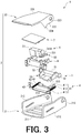
- Fig. 3 is an exploded perspective view of the locking device shown in Fig. 2 .
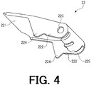
- Fig. 4 is a perspective view of a lock releasing operation member of the locking device shown in Fig. 2 .
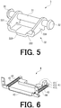
- Fig. 5 is a perspective view of a locking member of the locking device shown in Fig. 2 .
- Fig. 6 is a perspective view of a tongue guiding and discharging mechanism of the locking device shown in Fig. 2 .
- Fig. 7 is an exploded perspective view of a power generator of the locking device shown in Fig. 2 .
- Fig. 8 is a view showing a coil assembly of the power generator shown in Fig. 7 .
- FIG. 9 is a view showing an operation member of the power generator shown in Fig. 7 .
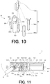
- Fig. 10 is a view showing a rotating member and a magnet assembly of the power generator shown in Fig. 7 .
- Fig. 11 is a top view showing an internal configuration of the power generator shown in Fig. 7 . In this regard, an upper plate of the power generator is omitted in Fig. 11 for showing the internal configuration of the power generator.
- an upper side in each of Figs. 2 to 10 is referred to as “upper” or “upper side”
- a lower side in each of Figs. 2 to 10 is referred to as “lower” or “lower side”
- a left side in each of Figs. 2 to 10 is referred to as “left” or “left side”
- a right side in each of Figs. 2 to 10 is referred to as “right” or “right side”.
- a rear side of the paper in each of Figs. 2 to 10 is referred to as “rear side”
- a front side of the paper in each of Figs. 2 to 10 is referred to as "front side”.
- a locking device 1 of the present invention shown in Figs. 2 and 3 is used for locking a tongue 200 in the locking device 1.
- the tongue 200 includes a plate-like portion 201, an engagement hole 202 for engaging with a locking member 3 (see Figs. 3 and 5 ) in the locking device 1 and a belt insertion hole 203 through which a belt (not shown in the drawings) is inserted.
- the engagement hole 202 is a substantially rectangular aperture formed in a tip end portion of the plate-like portion 201.
- the belt insertion hole 203 is a substantially rectangular aperture formed in a base end portion of the plate-like portion 201.
- a width of the tip end portion of the plate-like portion 201 is narrower than a width of a tongue insertion port 23 of a main body 2 of the locking device 1.
- the tip end portion of the plate-like portion 201 can be inserted into the main body 2 of the locking device 1 through the tongue insertion port 23.
- a width of the base end portion of the plate-like portion 201 is wider than the width of the tongue insertion port 23 of the main body 2 of the locking device 1.
- insertion of the tongue 200 into the main body 2 of the locking device 1 is restricted when the base end portion of the tongue 200 is engaged with an edge of the tongue insertion port 23 of the main body 2 of the locking device 1.
- a constituent material for the tongue 200 is not particularly limited to a specific kind. It is possible to form the tongue 200 with a metallic material or a resin material.
- the word of "tongue” in the specification broadly means a plate-like member in which the engagement hole 202 is formed in the tip end portion of the plate-like portion 201 for the locking as shown in Fig. 2 and which is used for fixing an arbitrary object.
- a tongue 200 can be used in a seat-belt device of a vehicle or an airplane in a state that the belt is inserted through the belt insertion hole 203 in the base end portion of the tongue 200.
- the tongue 200 can be used for fixing a cargo such as a container, a loaded object or the like in the state that the belt is inserted through the belt insertion hole 203 in the base end portion of the tongue 200.
- the tongue 200 can be used for restricting motion of an arbitrary object in a state that the belt is not inserted through the belt insertion hole 203 in the base end portion of the tongue 200.
- the tongue 200 may be provided at a cover of an opening and closing box which can be pivotally moved and a locking device such as the locking device 1 of the present invention may be provided at a main body portion (a containing portion) of the opening and closing box.
- a locking device such as the locking device 1 of the present invention may be provided at a main body portion (a containing portion) of the opening and closing box.
- the tongue 200 is inserted into the locking device provided at the main body portion of the opening and closing box to lock the tongue 200.
- the tongue 200 may be provided at a door pivotally moved and provided at a fixed arbitrary object such as a shelf and the locking device may be provided at the arbitrary fixed object such as a shelf. In such a usage state, the tongue 200 is inserted into the locking device provided at the fixed object to lock the tongue 200. By locking the tongue 200 in this manner, it is possible to restrict pivotal movement of the door and lock the door.
- the locking device 1 includes the main body 2 having the tongue insertion port 23 through which the tongue 200 is inserted, the locking member 3 for locking the tongue 200 when the tongue 200 inserted into the main body 2 through the tongue insertion port 23 reaches a predetermined position in the main body 2, a tongue guiding and discharging mechanism 4 having a tongue guiding and discharging member 41 for guiding the tongue 200 until the tongue 200 is locked by the locking member 3 when the tongue 200 is inserted into the main body 2 and discharging the tongue 200 when the lock of the tongue 200 due to the locking member 3 is released, a power generator 5 which can generate electric power at the time of inserting and discharging the tongue 200, a holding part 6 for fixedly holding the power generator 5 in the locking device 1 and a wireless transmitting part 7 driven by the electric power generated by the power generator 5.
- the main body 2 includes an outer frame 21 and a lock releasing operation member 22 serving as an operation member operated for releasing the lock of the tongue 200 due to the locking member 3 and also serving as a cover for the main body 2.
- Each component of the locking device 1 is contained in a space defined between the outer frame 21 and the lock releasing operation member 22.
- the outer frame 21 includes a bottom plate 211 and a pair of side walls 212 respectively extending from side portions of the bottom plate 211 toward the upper side.
- the outer frame 21 has a U-like shape opening toward the upper side.
- the bottom plate 211 and the pair of side walls 212 are formed integrally with each other.
- Through-holes 213 through which a pivotal movement shaft 31 of the locking member 3 described later is inserted are respectively formed in the pair of side walls 212 of the outer frame 21 on the rear side (the side from which the tongue 200 is inserted).
- the lock releasing operation member 22 includes an upper plate 221 and a pair of side walls 222 respectively extending toward the lower side from side portions of the upper plate 221 on the rear side (the side from which the tongue 200 is inserted). Further, the upper plate 221 and the pair of side walls 222 are formed integrally with each other. Through-holes 233 are respectively formed in the pair of side walls 222 at positions corresponding to the through-holes 213 of the pair of side walls 212 of the outer frame 21.
- positioning protrusions 224 to be engaged with the bottom plate 211 of the outer frame 21 to position the lock releasing operation member 22 in a state that the main body 2 has been assembled are respectively formed at lower end portions of the pair of side walls 222 on the front side.
- a half-round engagement portion 225 formed so as to cover the pivotal movement shaft 31 of the locking member 3 inserted through the through-holes 223 is provided at an end portion of the upper plate 221 on the rear side (the side from which the tongue 200 is inserted).
- the pivotal movement shaft 31 of the locking member 3 inserted through the through-holes 213 of the outer frame 21 and the through-holes 223 of the lock releasing operation member 22 is located in a space defined between the upper plate 221 and the half-round engagement portion 225 of the lock releasing operation member 22.
- the lock releasing operation member 22 By inserting the pivotal movement shaft 31 of the locking member 3 into the through-holes 213 of the outer frame 21 and the through-holes 223 of the lock releasing operation member 22 and respectively attaching fastening tools 32 to both ends of the pivotal movement shaft 31 of the locking member 3 in a state that the upper plate 221 of the lock releasing operation member 22 faces the bottom plate 211 of the outer frame 21 and the positioning protrusions 224 of the lock releasing operation member 22 make contact with the bottom plate 211 of the outer frame 21, the main body 2 is assembled. In the state that the main body 2 has been assembled, the lock releasing operation member 22 also serves as an upper cover for the main body 2.
- the tongue insertion port 23 is defined at an end portion of the main body 2 on the rear side (the side from which the tongue 200 is inserted) by the outer frame 21 and the lock releasing operation member 22.
- the tongue 200 is inserted into the main body 2 and discharged from the main body 2 through the tongue insertion port 23.
- the lock releasing operation member 22 can be pivotally moved around the pivotal movement shaft 31 of the locking member 3.
- the upper plate 221 of the lock releasing operation member 22 faces the bottom plate 211 of the outer frame 21.
- the lock releasing operation member 22 is pivotally moved around the pivotal movement shaft 31 of the locking member 3 toward the upper side so as to be separated from the outer frame 21.
- the locking member 3 includes the pivotal movement shaft 31, the fastening tools 32 respectively attached to both ends of the pivotal movement shaft 31 and a pivotally moving portion 33 provided so as to be pivotally moved around the pivotal movement shaft 31.
- the pivotally moving portion 33 includes a pair of arm portions 331 facing each other and having through-holes through which the pivotal movement shaft 31 is inserted, a plate-like portion 332 for connecting end portions of the pair of arm portions 331 and an engagement portion 333 formed so as to protrude from the plate-like portion 332 toward the lower side.
- the pair of arm portions 331, the plate-like portion 332 and the engagement portion 333 are formed integrally with each other.
- the engagement portion 333 is downwardly inclined at a substantially central portion of the plate-like portion 332 from the rear side (the side from which the tongue 200 is inserted) toward the front side.
- the tip end portion of the tongue 200 makes contact with an inclined lower surface of the engagement portion 333 and thus the pivotally moving portion 33 is pushed up and pivotally moved around the pivotal movement shaft 31.
- the engagement portion 333 of the pivotally moving portion 33 is inserted into the engagement hole 202 of the tongue 200, and thereby the tongue 200 is locked.
- the tongue guiding and discharging mechanism 4 includes the tongue guiding and discharging member 41 provided so as to be slidably moved along the insertion direction of the tongue 200, a support portion 42 fixedly provided on the outer frame 21 of the main body 2, a pair of guide shafts 43 fixedly attached to the support portion 42 and slidably holding the tongue guiding and discharging member 41 and coil springs 44 respectively attached to the pair of guide shafts 43.
- the tongue guiding and discharging member 41 includes a plate-like engagement portion 411 engaged with the tongue 200 at the time of inserting and discharging the tongue 200 and a contact portion 412 formed so as to protrude from an upper surface of the engagement portion 411.
- a tongue receiving concave portion 413 having a shape corresponding to the tip end portion of the tongue 200 is formed on the engagement portion 411 on the rear side (the side from which the tongue 200 is inserted).
- the tongue 200 inserted into the main body 2 through the tongue insertion port 23 is engaged with the tongue receiving concave portion 413 of the engagement portion 411 and guided by the tongue guiding and discharging member 41.
- Through-holes through which the guide shafts 43 are inserted are respectively formed on both end portions in a width direction of the engagement portion 411.
- the tongue guiding and discharging member 41 is held so as to be slidably moved along the insertion direction of the tongue 200.
- the coil springs 44 are respectively attached to the pair of guide shafts 43.
- the guide shafts 43 are respectively located in central hollow portions of the coil springs 44.
- the tongue guiding and discharging member 41 is slid in the main body 2 in the insertion direction of the tongue 200 to guide the tongue 200 until the tongue 200 reaches the predetermined position in the main body and the tongue 200 is locked by the locking member 3.
- the coil springs 44 keep a state that the coil springs 44 are elastically deformed.
- the contact portion 412 protrudes from the upper surface of the engagement portion 411 and always makes contact with an operation member 53 of the power generator 5 (see Figs. 3 , 7 and 9 ) in a state that the locking device 1 has been assembled.
- the contact portion 412 pushes the operation member 53 of the power generator 5.
- the operation member 53 is pivotally moved from a predetermined initial position in a first direction in a plane parallel to the insertion direction of the tongue 200, and thereby external force is applied to the power generator 5 through the operation member 53.
- the tongue guiding and discharging member 41 is slid in the discharging direction of the tongue 200 as described above and the tongue 200 is discharged from the main body 2.
- the operation member 53 of the power generator 5 is pivotally moved in a second direction opposite to the first direction in the plane parallel to the insertion direction of the tongue 200 so as to return to the predetermined initial position and the power generator 5 performs second power generation.
- the electric power generated in the first power generation and the second power generation of the power generator 5 is supplied to the wireless transmitting part 7.
- the wireless transmitting part 7 is driven by the electric power supplied from the power generator 5 and a signal is transmitted to an external device such as a management device.
- the power generator 5 is held by the holding part 6 fixedly provided on the outer frame 21 and thus fixedly provided in the main body 2. Further, power lead wires (not shown in the drawings) of the power generator 5 are connected to the wireless transmitting part 7.
- the wireless transmitting part 7 is fixedly provided in the main body 2 and has a function of wirelessly transmitting the signal to the external device such as a management device by utilizing the electric power generated by the power generator 5.
- the external device can receive and analyze the signal wirelessly transmitted from the wireless transmitting part 7 to determine whether or not the tongue 200 is now locked by the locking device 1.
- the power generator 5 used in the present invention will be described in detail with reference to Fig. 7 .
- the upper side and the lower side of the power generator 5 are inverted between Figs. 3 and 7 .
- the power generator 5 is arranged in the locking device 1 shown in Fig. 3 with being turned upside down from the perspective view shown in Fig. 7 .
- the power generator 5 shown in Fig. 7 includes a case 51 (see Fig. 3 ) for containing each component of the power generator 5, a coil assembly 52 containing a coil 522 fixedly provided in the case 51, the operation member 53 provided so as to be pivotally moved with respect to the case 51 around a first axis member 54a in the plane parallel to the insertion direction of the tongue 200 when the operation member 53 is operated by the contact portion 412 of the tongue guiding and discharging member 41 for applying the external force, a rotating member 55 provided so as to be rotated by the operation member 53, a magnet assembly 56 containing a first magnet 561a and a second magnet 561b attached to the rotating member 55 so that the first magnet 561a and the second magnet 561b can be rotated and moved with respect to the coil 522, an upper torsion spring 57a and a lower torsion spring 57b for storing the external force applied from the contact portion 412 of the tongue guiding and discharging member 41 through the operation member 53 as elastic energy and
- an arm portion 531 of the operation member 53 protrudes from the case 51 toward the outside.
- the contact portion 412 of the tongue guiding and discharging member 41 contacting with the operation member 53 pushes the operation member 53 and applies the external force so as to pivotally move the operation member 53 in the plane parallel to the insertion direction of the tongue 200.
- the power generator 5 performs the first power generation and the second power generation by utilizing the external force applied through the tongue guiding and discharging member 41.
- the case 51 is an elongated box-like member (with a size of about 8 mm width x about 12 mm height x about 33 mm length, for example) for containing each component of the power generator 5. As shown in Fig. 7 , the case 51 includes a lower plate 511, an upper plate 512, a movable portion containing portion 513 for containing movable portions of the power generator 5 and an external core portion 514 which contains the coil assembly 52 and serves as an external core for the coil 522.
- the lower plate 511 is an elongated plate-like member serving as a base plate for the entire of the power generator 5.
- the movable portion containing portion 513 is integrally formed on a left-side portion of an upper surface of the lower plate 511.
- the movable portion containing portion 513 is constituted of four plate-like portions surrounding a space for containing the movable portions of the power generator 5.
- slits 5131, 5132, 5133 through which a magnetic core 523 of the coil assembly 52, a first plate-like portion 5141 and a second plate-like portion 5142 of the external core portion 514 are respectively inserted are formed in a right-side surface of the movable portion containing portion 513.
- a right-side end portion of the lower plate 511 is configured to be engaged with the external core portion 514.
- a cutout portion 5134 is formed in a left-side portion of the movable portion containing portion 513. As shown in Fig. 3 , in the state that the power generator 5 has been assembled, the arm portion 531 of the operation member 53 protrudes toward the outside of the case 51 through the cutout portion 5134.
- the first axis member 54a and a second axis member 54b are fixedly provided on the upper surface of the lower plate 511 and in the movable portion containing portion 513.
- the first axis member 54a includes a first support portion 541a for supporting a lower surface of the operation member 53 and a first axis 542a formed on the first support portion 541a.
- the first support portion 541a is a columnar member and inserted into a central hollow portion of a torsion spring 58 for biasing the operation member 53 in the state shown in Fig. 11 in that the power generator 5 has been assembled.
- the first axis 542a is a columnar member formed on a substantially central portion of an upper surface of the first support portion 541a and inserted into an axis insertion hole 532 of the operation member 53 in the state shown in Fig. 11 in that the power generator 5 has been assembled.
- a diameter of the first support portion 541a is larger than a diameter of the axis insertion hole 532 and thus the operation member 53 is supported on the first support portion 541a in the state shown in Fig. 11 in that the power generator 5 has been assembled.
- the second axis member 54b includes a second support portion 541b for supporting a lower surface of the rotating member 55 and a second axis 542b formed on the second support portion 541b.
- the second support portion 541b is a columnar member and inserted into a central hollow portion of the lower torsion spring 57b in the state shown in Fig. 11 in that the power generator 5 has been assembled.
- the second axis 542b is a columnar member formed on a substantially central portion of an upper surface of the second support portion 541b and inserted into an axis insertion hole 553 of the rotating member 55 in the state shown in Fig. 11 in that the power generator 5 has been assembled.
- a diameter of the second support portion 541b is larger than a diameter of the axis insertion hole 553 and thus the rotating member 55 is supported on the second support portion 541b in the state shown in Fig 11 in that the power generator 5 has been assembled.
- the upper plate 512 is an elongated plate-like member serving as a cover for the entire of the power generator 5.
- the upper plate 512 includes a first insertion hole 5121 for supporting an end portion of the first axis 542a and a second insertion hole 5122 for supporting an end portion of the second axis 542b.
- the first insertion hole 5121 is formed at a position corresponding to the first axis 542a on the lower plate 511.
- the second insertion hole 5122 is formed at a position corresponding to the second axis 542b on the lower plate 511.
- a right-side end portion of the upper plate 512 is configured to be engaged with the external core portion 514.
- a left-side end portion of the upper plate 512 is configured to form an opening portion through which the arm portion 531 of the operation member 53 protrudes from the case 51 in corporation with the cutout portion 5134 of the movable portion containing portion 513 on the lower plate 511.
- the lower plate 511, the upper plate 512 and the movable portion containing portion 513 of the case 51 described above it is possible to use a non-magnetic material and a weakly magnetic material.
- the lower plate 511, the upper plate 512 and the movable portion containing portion 513 may be formed with the same non-magnetic material or weakly magnetic material or may be formed with different kinds of the non-magnetic material or weakly magnetic material.
- the external core portion 514 includes the first plate-like portion 5141, the second plate-like portion 5142 facing the first plate-like portion 5141 and a connecting portion 5143 for connecting the first plate-like portion 5141 and the second plate-like portion 5142.
- the coil assembly 52 (the coil 522) is contained between the first plate-like portion 5141 and the second plate-like portion 5142.
- Each component (the first plate-like portion 5141, the second plate-like portion 5142 and the connecting portion 5143) of the external core portion 514 is formed with a magnetic material and serves as the external core of the coil assembly 52 (the coil 522).
- the magnetic material for forming the external core portion 514 include a ferritic stainless steel (for example, JIS SUS 430), a cold rolled steel (for example, SPCC), a martensitic stainless steel (for example, JIS SUS 420), a pure iron (for example, JIS SUY), a soft iron, a carbon steel, a magnetic steel (a silicon steel), a high-speed tool steel, a structural steel (for example, JIS SS 400), a permalloy and a combination of two of more of these materials.
- a ferritic stainless steel for example, JIS SUS 430
- SPCC cold rolled steel
- a martensitic stainless steel for example, JIS SUS 420
- a pure iron for example, JIS
- the external core portion 514 it is especially preferable to form the external core portion 514 with the ferritic stainless steel having superior strength and corrosion resistance or the cold rolled steel having superior formability and workability.
- Each component of the external core portion 514 may be formed with the same magnetic material or may be formed with different kinds of the magnetic material.
- the external core portion 514 can serve as a part of a magnetic circuit in which magnetic flux (lines of magnetic force) generated from the magnets 561a, 561b and passing through the coil 522 flows.
- the first plate-like portion 5141 is an elongated plate-like member.
- a first bent portion 5144 is formed at a left-side end of the first plate-like portion 5141.
- the first bent portion 5144 is formed by bending the left-side end of the first plate-like portion 5141 toward the inner side (the rear side in Fig. 7 ). Further, the first bent portion 5144 is configured so that a left-side end portion of the first bent portion 5144 faces an end portion of the first magnet 561a during motion of the power generator 5 described with reference to Figs. 12A to 12D and 13A to 13D .
- the second plate-like portion 5142 is an elongated plate-like member which is the substantially same as the first plate-like portion 5141.
- a second bent portion 5145 is formed at a left-side end of the second plate-like portion 5142.
- the second bent portion 5145 is formed by bending the left-side end of the second plate-like portion 5142 toward the inner side (the front side in Fig. 7 ). Further, the second bent portion 5145 is configured so that a left-side end portion of the second bent portion 5145 faces an end portion of the second magnet 561b during the motion of the power generator 5 described with reference to Figs. 12A to 12D and 13Ato 13D .
- the first bent portion 5144 of the first plate-like portion 5141 is inserted through the slit 5132 of the movable portion containing portion 513 of the case 51 and thus the left-side end portion of the first bent portion 5144 is located in the movable portion containing portion 513.
- the second bent portion 5145 of the second plate-like portion 5142 is inserted through the slit 5133 of the movable portion containing portion 513 of the case 51 and thus the left-side end portion of the second bent portion 5145 is located in the movable portion containing portion 513.
- first plate-like portion 5141, the second plate-like portion 5142 and the connecting portion 5143 are formed integrally with each other in this embodiment, the present invention is not limited thereto.
- all of the first plate-like portion 5141, the second plate-like portion 5142 and the connecting portion 5143 may be formed as different components or the connecting portion 5143 may be formed integrally with one of the first plate-like portion 5141 and the second plate-like portion 5142.
- the coil assembly 52 includes a bobbin 521, the coil 522 formed by winding a wire on an outer periphery of the bobbin 521 and the magnetic core 523 inserted into a central hollow portion of the bobbin 521 (a central hollow portion of the coil 522).
- the coil assembly 52 is fixedly arranged on the lower plate 511 of the case 51. Further, in the state shown in Fig. 11 in that the power generator 5 has been assembled, the coil assembly 52 is located between the first plate-like portion 5141 and the second plate-like portion 5142 of the external core portion 514 of the case 51.
- a method for fixedly arranging the coil assembly 52 on the lower plate 511 of the case 51 is not particularly limited to a specific method. It is possible to fixedly arrange the coil assembly 52 on the lower plate 511 with a bonding method due to an adhesive agent, a thermal fusion method, a fixing method due to a fixing tool such as a screw and a combination of two or more of these methods.
- the coil 522 is formed by winding the wire around the bobbin 521 so that a cross-sectional shape of the coil 522 becomes a flattened elliptical shape.
- the magnetic core 523 is a plate-like member having a size and a shape which can be inserted into the central hollow portion of the bobbin 521 (the central hollow portion of the coil 522) and formed with the same or similar magnetic material as the external core portion 514 of the case 51.
- the wire for forming the coil 522 is not limited to a specific kind.
- the wire include a wire obtained by covering a copper base line with an insulating layer, a wire obtained by covering a copper base line with an insulating layer to which an adhesive (fusion) function is imparted and a combination of two or more of these wires.
- a cross-sectional shape of the wire may be any shape.
- the cross-sectional shape of the wire include a polygonal shape such as a triangular shape, a square shape, a rectangular shape and a hexagonal shape; a circular shape and an elliptical shape.
- the operation member 53 is a member which is operated by the contact portion 412 of the tongue guiding and discharging member 41 so as to be pivotally moved around the first axis 542a in the plane parallel to the insertion direction of the tongue 200 for applying the external force to the power generator 5.
- the operation member 53 includes the elongated arm portion 531, the axis insertion hole 532 through which the first axis 542a is inserted, a through-hole 533 for receiving an end portion 582 of the torsion spring 58 and an engagement portion 534 to be engaged with the rotating member 55.
- the axis insertion hole 532 is formed in the arm portion 531 so as to pass through the arm portion 531 in a thickness direction thereof and configured so that the first axis 542a of the first axis member 54a can be inserted into the axis insertion hole 532.
- the through-hole 533 is formed in a portion of the arm portion 531 outwardly protruding from a portion in which the axis insertion hole 532 is formed so as to pass through the arm portion 531 in the thickness direction thereof. Further, the through-hole 533 is configured to receive the end portion 582 of the torsion spring 58.
- the engagement portion 534 is a rectangular columnar member formed so as to protrude from an end portion of the arm portion 531 toward the outside and configured to be engaged with an engagement portion 556 of the rotating member 55 described later during the motion of the power generator 5 described with reference to Figs. 12A to 12D and 13A to 13D .
- the first axis 542a of the first axis member 54a is inserted into the axis insertion hole 532 of the operation member 53, the end portion 582 of the torsion spring 58 is inserted into the through-hole 533 and the lower surface of the operation member 53 is supported by the first support portion 541a of the first axis member 54a.
- this configuration it is possible to support the operation member 53 so that the operation member 53 can be pivotally moved with respect to the case 51 around the first axis 542a.
- the rotating member 55 is provided in the case 51 so as to be rotated by the operation member 53 and supports the magnet assembly 56 (the magnets 561a, 561b).
- the rotating member 55 includes a main body 551, a columnar spring fitting axis 552 provided on an upper surface of the main body 551, an axis insertion hole 553 formed in a substantially central portion of an upper surface of the spring fitting axis 552, a magnet assembly attachment portion 554 formed on a right-side surface of the main body 551, a pair of spring end portion support portions 555a, 555b (see Fig. 11 ) formed on a surface opposite to the surface of the main body 551 on which the magnet assembly attachment portion 554 is formed and the engagement portion 556 formed so as to protrude from a left-end surface of the main body 551 toward the outside.
- the spring fitting axis 552 is provided on the upper surface of the main body 551 and inserted into a central hollow portion of the upper torsion spring 57a in the state shown in Fig. 11 in that the power generator 5 has been assembled.
- a height of the spring fitting axis 552 is substantially equal to a height of the central hollow portion of the upper torsion spring 57a.
- the axis insertion hole 553 is formed in the substantially central portion of the upper surface of the spring fitting axis 552 so as to pass through the main body 551 and the spring fitting axis 552 in the thickness direction thereof.
- the second axis 542b is inserted into the axis insertion hole 553.
- the magnet assembly attachment portion 554 is a concave portion having a V-shape and formed on the right-side surface of the main body 551. In the state shown in Fig. 11 in that the power generator 5 has been assembled, the magnet assembly 56 is attached to the magnet assembly attachment portion 554.
- the pair of spring end portion support portion 555a, 555b are concave portions formed so as to be vertically symmetry through the spring fitting axis 552 in a top view of the rotating member 55.
- an end portion 571b of the lower torsion spring 57b is inserted into the spring end portion support portion 555a and an end portion 572a of the upper torsion spring 57a is inserted into the spring end portion support portion 555b.
- the rotating member 55 is supported by the upper torsion spring 57a and the lower torsion spring 57b.
- the engagement portion 556 is formed so as to protrude from the left-side surface of the main body 551 toward the outside and configured to be engaged with the engagement portion 534 of the operation member 53 during the motion of the power generator 5 described with reference to Figs. 12A to 12D and 13A to 13D .
- the rotating member 55 is formed with a non-magnetic material or a weakly magnetic material. Among non-magnetic materials and weak magnetic materials, it is preferable to form the rotating member 55 with a POM (polyacetal) whose weight is light. By forming the rotating member 55 with the POM whose weight is light, it is possible to improve slidability of the rotating member 55. Further, each component of the rotating member 55 described above may be formed integrally with each other or may be formed as different components.
- the magnet assembly 56 includes a yoke 562 attached to the magnet assembly attachment portion 554, and the first magnet 561a and the second magnet 561b attached to the yoke 262.
- the yoke 562 has a V-shape corresponding to the V-shape of the magnet assembly attachment portion 554 and is configured so that a V-shaped inner surface of the yoke 562 fits with the V-shaped outer surface of the magnet assembly attachment portion 554.
- the yoke 562 is formed with the same or similar magnetic material as the external core portion 514 of the case 51 and thus can serve as a part of the magnetic circuit in which the magnetic flux (the lines of magnetic force) passing through the coil 522 flows.
- the first magnet 561a and the second magnet 561b are respectively attached to outer surfaces of two inclined planes of the yoke 562 forming the V-shape due to their own magnetic force.
- the first magnet 561a and the second magnet 561b may be attached to the yoke 562 due to an adhesive agent or the like in addition to their own magnetic force. With this configuration, it is possible to reliably prevent the first magnet 561a and the second magnet 561b from being shifted on the yoke 562 and left from the yoke 562.
- Each of the first magnet 561a and the second magnet 561b is the same kind of magnet having the same rectangular columnar shape and the same magnetic force.
- the first magnet 561a is attached to one of the two inclined planes of the yoke 562 forming the V-shape so that a north pole plane of the first magnet 561a faces the yoke 562.
- the second magnet 561b is attached to the other one of the two inclined planes of the yoke 562 forming the V-shape so that a south pole plane of the second magnet 561b faces the yoke 562.
- the magnets 561a, 561b it is possible to use an alnico magnet, a ferrite magnet, a neodymium magnet, a samarium-cobalt magnet, a magnet (a bonded magnet) obtained by molding a composite material prepared by pulverizing and mixing at least one of these magnets with a resin material or a rubber material, or the like. Among them, it is preferable to use the neodymium magnet having strong magnetic force or the samarium-cobalt magnet having high heat resistance as the magnets 561a, 561b.
- the magnet assembly 56 is attached to the magnet assembly attachment portion 554 of the rotating member 55.
- the magnet assembly 56 is rotated and moved with respect to the coil 522 around the second axis 542b.
- the magnets 561a, 561b are relatively rotated and moved with respect to the coil 522 around the second axis 542b.
- the magnets 561a, 561b are relatively moved with respect to the coil 522, the number of the lines of magnetic force (the density of the magnetic flux) passing through the coil 522 varies, thereby generating the electromotive voltage in the coil 522.
- the coil 522 (the coil assembly 52) and the magnets 561a, 561b (the magnet assembly 56) which are relatively rotated and moved with respect to the coil 522 form a power generating unit for generating the electric power.
- Each of the upper torsion spring 57a and the lower torsion spring 57b has the same configuration with each other and is arranged so as to be vertically symmetric through the rotating member 55 in the state shown in Fig. 11 in that the power generator 5 has been assembled.
- the lower torsion spring 57b is placed on the lower plate 511 of the case 51 and positioned below the rotating member 55. Further, the second support portion 541b of the second axis member 54b is inserted into the central hollow portion of the lower torsion spring 57b.
- the one end portion 571b of the lower torsion spring 57b is inserted into the spring end portion support portion 555a of the rotating member 55 to support the one end portion 571b of the lower torsion spring 57b and the other end portion 572b of the lower torsion spring 57b is engaged with an inner surface of the movable portion containing portion 513 of the case 51 to support the other end portion 572b of the lower torsion spring 57b.
- the upper torsion spring 57a is placed on the upper surface of the main body 551 of the rotating member 55 and positioned above the rotating member 55. Further, the spring fitting axis 552 of the rotating member 55 is inserted into the central hollow portion of the upper torsion spring 57a.
- the one end portion 571a of the upper torsion spring 57a is engaged with the inner surface of the movable portion containing portion 513 of the case 51 to support the one end portion 571a of the upper torsion spring 57a and the other end portion 572a of the upper torsion spring 57a is inserted into the spring end portion support portion 555b of the rotating member 55 to support the other end portion 572a of the upper torsion spring 57a.
- the magnet assembly 56 is attached to the magnet assembly attachment portion 554 of the rotating member 55 as described above, the magnets 561a, 561b of the magnet assembly 56 are also rapidly rotated and moved with respect to the coil 522 around the second axis 542b when the rotating member 55 is rapidly rotated around the second axis 542b.
- each of the upper torsion spring 57a and the lower torsion spring 57b serves as an elastic member for storing the external force applied through the tongue guiding and discharging member 41 as the elastic energy and releasing the stored elastic energy to relatively rotate and move the magnets 561a, 561b with respect to the coil 522.
- the torsion spring 58 is a member for holding the operation member 53 at a predetermined initial position. In the state shown in Fig. 11 in that the power generator 5 has been assembled, the torsion spring 58 is placed on the lower plate 511 of the case 51 and positioned below the operation member 53. Further, the first support portion 541a of the first axis member 54a is inserted into the central hollow portion of the torsion spring 58.
- the one end portion 581 of the torsion spring 58 is engaged with the inner surface of the movable portion containing portion 513 of the case 51 to support the one end portion 581 of the torsion spring 58 and the other end portion 582 of the torsion spring 58 is inserted into the through-hole 533 of the operation member 53 to support the other end portion 582 of the torsion spring 58. With this configuration, it is possible to hold the operation member 53 at the predetermined initial position.
- Figs. 12A to 12D are views for explaining motion of the first power generation of the power generator shown in Fig. 7 .
- Figs. 13A to 13D are views for explaining motion of the second power generation of the power generator shown in Fig. 7 .
- the upper plate 512 of the power generator 5 is omitted for showing the internal configuration of the power generator 5 in Figs. 12A to 12D and 13A to 13D .
- Fig. 12A shows a top view of the power generator 5 in an initial state that the power generator 5 has been assembled and the external force is not applied to the operation member 53 through the tongue guiding and discharging member 41.
- the engagement portion 534 of the operation member 53 is separated from the engagement portion 556 of the rotating member 55 by a predetermined distance.
- the first magnet 561a and the second magnet 561b are positioned so as to be separated from the external core portion 514 of the case 51 and the magnetic core 523 of the coil assembly 52 by a predetermined distance.
- the first magnet 561a is positioned between the first bent portion 5144 of the first plate-like portion 5141 of the external core portion 514 and the magnetic core 523 of the coil assembly 52 and the second magnet 561b is positioned between the second bent portion 5145 of the second plate-like portion 5142 of the external core portion 514 and the magnetic core 523 of the coil assembly 52.
- Fig. 12B shows the top view of the power generator 5 in a state that the operation member 53 is pivotally moved in the clockwise direction (a first direction) in Fig. 12B around the first axis 542a by the external force applied to the operation member 53 through the tongue guiding and discharging member 41 and the engagement portion 534 of the operation member 53 is engaged with the engagement portion 556 of the rotating member 55.
- the contact portion 412 of the tongue guiding and discharging member 41 contacting with the operation member 53 pushes the operation member 53 and thus the external force is applied to the operation member 53 so as to pivotally move the operation member 53 from the predetermined initial position in the clockwise direction in the plane parallel to the insertion direction of the tongue 200.
- the operation member 53 is pivotally moved in the clockwise direction in Fig. 12B around the first axis 542a.
- the engagement portion 534 of the operation member 53 is engaged with the engagement portion 556 of the rotating member 55.
- the rotating member 55 is rotated in the counter-clockwise direction around the second axis 542b by the operation member 53.
- the magnets 561a, 561b attached to the rotating member 55 are also relatively rotated and moved with respect to the coil 522 in the counter-clockwise direction around the second axis 542b.
- the engagement between the engagement portion 534 of the operation member 53 and the engagement portion 556 of the rotating member 55 is kept until the magnets 561a, 561b attached to the rotating member 55 reach a first engagement release position due to the rotational movement.
- the upper torsion spring 57a and the lower torsion spring 57b supporting the rotating member 55 are elastically deformed, and thereby the applied external force is stored in the upper torsion spring 57a and the lower torsion spring 57b as the elastic energy.
- the torsion spring 58 supporting the operation member 53 is also elastically deformed, and thereby the applied external force is stored in the torsion spring 58 as the elastic energy.
- the electromotive voltage generated in the coil 522 when the magnets 561a, 561b are relatively rotated and moved with respect to the coil 522 by the external force applied through the tongue guiding and discharging member 41 does not substantially contribute to the amount of the electric power generated by the power generator 5.
- Fig. 12C shows the top view of the power generator 5 when the magnets 561a, 561b attached to the rotating member 55 reach the first engagement release position and the engagement between the engagement portion 534 of the operation member 53 and the engagement portion 556 of the rotating member 55 is released for starting the first power generation.
- the tongue 200 When the tongue 200 is inserted into the main body 2 and reaches the predetermined position in the main body 2, the tongue 200 is locked by the locking member 3. At this time, the magnets 561a, 561b attached to the rotating member 55 reach the first engagement release position and the engagement between the engagement portion 534 of the operation member 53 and the engagement portion 556 of the rotating member 55 is released, and thereby the first power generation is started.
- the magnetic circuit is formed by the second magnet 561b, the external core portion 514 (the second plate-like portion 5142 and the connecting portion 5143), the magnetic core 523, the first magnet 561a and the yoke 562.
- the lines of magnetic force flowing in the magnetic circuit in the clockwise direction pass through the coil 522 from the right side to the left side.
- first magnet 561a takes a closest position with respect to the magnetic core 523 (the coil 522) of the coil assembly 52
- a right-side end surface (a south pole plane) of the first magnet 561a approximately horizontally faces a left-side end surface of the magnetic core 523 of the coil assembly 52.
- second magnet 561b takes a closest position with respect to the second bent portion 5145
- a right-side end surface (a north pole plane) of the second magnet 561b faces a left-side end surface of the second bent portion 5145.
- Fig. 12D shows the top view of the power generator 5 at the time when the first power generation of the power generator 5 finishes.
- the magnetic circuit is formed by the second magnet 561b, the magnetic core 523, the external core portion 514 (the connecting portion 5143 and the first plate-like portion 5141), the first magnet 561a and the yoke 562.
- the lines of magnetic force flowing in the magnetic circuit in the clockwise direction pass through the coil 522 from the left side to the right side. Since the lines of magnetic force pass through the coil 522 from the right side to the left side in the state shown in Fig. 12C , a direction of the lines of magnetic force passing through the coil 522 is inverted in a first power generating zone in which the power generator 5 shifts from the state shown in Fig. 12C to the state shown in Fig. 12D .
- the right-side end surface (the south pole plane) of the first magnet 561a faces a left-side end surface of the first bent portion 5144.
- the second magnet 561b takes a closest position with respect to the magnetic core 523 (the coil 522)
- the right-side end surface (the north pole plane) of the second magnet 561b approximately horizontally faces the left-side end surface of the magnetic core 523.
- Fig. 13A shows the top view of the power generator 5 after the state shown in Fig. 12D , that is in a state that the first power generation finishes.
- the rotating member 55 is rotated in the counter-clockwise direction by the upper torsion spring 57a and the lower torsion spring 57b and the rotating member 55 returns to the initial state.
- the lock of the tongue 200 due to the locking member 3 is kept and the elastic energy remains in the torsion spring 58 supporting the operation member 53.
- Fig. 13B shows the top view of the power generator 5 in a state that the engagement portion 534 of the operation member 53 is again engaged with the engagement portion 556 of the rotating member 55 after the lock of the tongue 200 due to the locking member 3 is released.
- the lock of the tongue 200 due to the locking member 3 is released.
- the elastic energy stored in the torsion spring 58 is released to pivotally move the operation member 53 in the counter-clockwise direction (a second direction) so as to return to the operation member 53 to the predetermined initial position and thus the engagement portion 534 of the operation member 53 is again engaged with the engagement portion 556 of the rotating member 55.
- the power generator 5 shifts to a state shown in Fig. 13B .
- spring constants of the torsion spring 58, the upper torsion spring 57a and the lower torsion spring 57b and the shapes of the operation member 53 and the rotating member 55 are adjusted so that rotary torque applied from the operation member 53 to the rotating member 55 is larger than rotary torque applied from the rotating member 55 to the operation member 53 in the state shown in Fig. 13B .
- the engagement between the engagement portion 534 of the operation member 53 and the engagement portion 556 of the rotating member 55 is kept until the magnets 561a, 561b attached to the rotating member 55 reach a second engagement release position due to the rotational movement.
- a magnitude relationship between the rotary torque applied from the operation member 53 to the rotating member 55 and the rotary torque applied from the rotating member 55 to the operation member 53 is kept until the magnets 561a, 561b reach the second engagement release position due to the rotational movement.
- the upper torsion spring 57a and the lower torsion spring 57b supporting the rotating member 55 are elastically deformed, and thereby the applied external force is stored in the upper torsion spring 57a and the lower torsion spring 57b as the elastic energy.
- the magnets 561a, 561b are relatively rotated and moved with respect to the coil 522 and thus the density of the magnetic flux passing through the coil 522 varies.
- the speed of the rotational movement of the magnets 561a, 561b due to the operation member 53 is slower than the time scale of the electromagnetic phenomenon, an amount of the electric power generated in the coil 522 by this rotational movement is significantly small.
- the electromotive voltage generated in the coil 522 when the magnets 561a, 561b are relatively rotated and moved with respect to the coil 522 by the operation member 53 does not substantially contribute to the amount of the electric power generated by the power generator 5.
- Fig. 13C shows the top view of the power generator 5 when the magnets 561a, 561b attached to the rotating member 55 reach the second engagement release position due to the rotational movement and the engagement between the engagement portion 534 of the operation member 53 and the engagement portion 556 of the rotating member 55 is again released.
- the magnetic circuit is formed by the second magnet 561b, the magnetic core 523, the external core portion 514 (the connecting portion 5143 and the first plate-like portion 5141), the first magnet 561a and the yoke 562.
- the lines of magnetic force flowing in the magnetic circuit in the clockwise direction pass through the coil 522 from the left side to the right side.
- Fig. 13D shows the top view of the power generator 5 at the time when the second power generation of the power generator 5 finishes.
- the magnetic circuit is formed by the second magnet 561b, the external core portion 514 (the second plate-like portion 5142 and the connecting portion 5143), the magnetic core 523, the first magnet 561a and the yoke 562.
- the lines of magnetic force flowing in the magnetic circuit in the clockwise direction pass through the coil 522 from the right side to the left side. Since the lines of magnetic force pass through the coil 522 from the left side to the right side in the state shown in Fig. 13C , the direction of the lines of magnetic force passing through the coil 522 is inverted in a second power generating zone in which the power generator 5 shifts from the state shown in Fig. 13C to the state shown in Fig. 13D .
- the power generator 5 can perform the first power generation and the second power generation by utilizing the applied external force by utilizing the external force applied to the operation member 53 through the contact portion 412 of the tongue guiding and discharging member 41.
- the rotational direction of the magnets 561a, 561b at the first power generation performed when the tongue 200 is inserted into the main body 2 and the tongue 200 is locked by the locking member 3 is opposite to the rotational direction of the magnets 561a, 561b at the second power generation performed when the lock of the tongue 200 due to the locking member 3 is released and the tongue 200 is discharged from the main body 2.
- positive and negative of the electromotive voltage generated in the coil 522 at the first power generation are different from positive and negative of the electromotive voltage generated in the coil 522 at the second power generation.
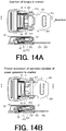
- Fig. 14A is a view for explaining motion when the tongue is inserted into the locking device shown in Fig. 2 .
- Fig. 14B is a view for explaining motion when the operation member of the power generator is pivotally moved in the locking device shown in Fig. 2 .
- Fig. 14C is a view for explaining motion when the tongue is locked and the first power generation is performed in the locking device shown in Fig. 2 .
- Fig. 14D is a view for explaining motion when the lock of the tongue is released and the tongue is discharged from the locking device shown in Fig. 2 .
- Fig. 14E is a view for explaining motion when the tongue is discharged and the second power generation is performed in the locking device shown in Fig. 2 .
- FIG. 14A to 14E contains a top view of the locking device 1 and a cross-sectional view taken along an A-A line in the top view. Further, for the purpose of illustrating the internal configuration of the locking device 1, the lock releasing operation member 22 serving as the cover for the main body 2 of the locking device 1 and the wireless transmitting part 7 are omitted in the top view of each of Figs. 14A to 14E .
- Fig. 14A shows the top view of the locking device 1 and the tongue 200 when the tongue 200 is inserted into the main body 2 of the locking device 1 through the tongue insertion port 23.
- the tip end portion of the tongue 200 is engaged with the tongue receiving concave portion 413 of the tongue guiding and discharging member 41 and the tongue 200 is guided by the tongue guiding and discharging member 41.
- the tip end portion of the tongue 200 makes contact with the lower surface of the engagement portion 333 of the locking member 3, and thereby the pivotally moving portion 33 of the locking member 3 is pivotally moved and pushed up around the pivotal movement shaft 31.
- the pivotally moving portion 33 of the locking member 3 is further pushed up by the tongue 200 from the state shown in Fig. 14A and the engagement portion 333 of the pivotally moving portion 33 of the locking member 3 is positioned on the plate-like portion 201 of the tongue 200.
- the contact portion 412 of the tongue guiding and discharging member 41 contacting with the operation member 53 of the power generator 5 pushes the operation member 53 of the power generator 5.
- the operation member 53 of the power generator 5 is pivotally moved from the predetermined initial position in the first direction in the plane parallel to the insertion direction of the tongue 200.
- the coil springs 44 of the tongue guiding and discharging mechanism 4 are elastically deformed due to the sliding movement of the tongue guiding and discharging member 41 in the insertion direction of the tongue 200.
- the engagement portion 333 of the pivotally moving portion 33 of the locking member 3 on the plate-like portion 201 of the tongue 200 is inserted into the engagement hole 202 of the tongue 200, and thereby the tongue 200 is locked by the locking member 3.
- the operation member 53 of the power generator 5 is further pivotally moved by the contact portion 412 of the tongue guiding and discharging member 41 from the state shown in Fig. 14B .
- the power generator 5 shifts to the state described with reference to Fig. 12C and performs the first power generation.
- the wireless transmitting part 7 is driven by the electric power generated by the power generator 5.
- the wireless transmitting part 7 identifies the positive and negative of the electromotive voltage generated in the coil 522 to determine that the tongue 200 is inserted into the main body 2 and locked by the locking member 3 and wirelessly transmits a signal indicating that the tongue 200 is locked by the locking device 1 to the external device such as a management device.
- the operation member 53 of the power generator 5 is pivotally moved in the second direction in the plane parallel to the insertion direction of the tongue 200 due to the action of the torsion spring 58 of the power generator 5. As a result, the operation member 53 returns to the predetermined initial position.
- the tongue 200 is further discharged from the main body 2 by the tongue guiding and discharging member 41. Further, the operation member 53 of the power generator 5 is further pivotally moved from the state shown in Fig. 14D . At this time, the power generator 5 shifts to the state described with reference to Fig. 13C and performs the second power generation. When the power generator 5 performs the second power generation, the wireless transmitting part 7 is driven by the electric power generated by the power generator 5.
- the wireless transmitting part 7 identifies the positive and negative of the electromotive voltage generated in the coil 522 to determine that the lock of the tongue 200 is released and discharged from the main body 2 of the locking device 1 and wirelessly transmits a signal indicating that the lock of the tongue 200 is released and the tongue 200 is discharged from the main body 2 of the locking device 1 to the external device such as a management device.
- the operation member 53 of the power generator 5 is pivotally moved in the plane parallel to the insertion direction of the tongue 200 by utilizing the horizontal movement caused by the insertion of the tongue 200 into the main body 2 of the locking device 1 and the discharging of the tongue 200 from the main body 2 of the locking device 1 to allow the power generator 5 to perform the first power generation and the second power generation and drive the wireless transmitting part 7.
- the locking device 1 of the present invention it becomes unnecessary to ensure a space for converting the horizontal movement caused by the insertion of the tongue 200 into the main body 2 of the locking device 1 into pivotal movement in a plane perpendicular to the insertion direction of the tongue 200 unlike the above-described conventional art. Thus, it is possible to reduce a thickness of the locking device 1 of the present invention.
- the contact portion 412 is formed on the engagement portion 411 of the tongue guiding and discharging member 41 to enable the horizontal movement caused by the insertion of the tongue 200 into the main body 2 of the locking device 1 to be converted into the pivotal movement of the operation member 53 of the power generator 5.
- the locking device 1 of the present invention additional assemblies are not required for pivotally moving the operation member 53 of the power generator 5 by utilizing the horizontal movement caused by the insertion of the tongue 200 into the main body 2 of the locking device 1 unlike the above-mentioned conventional art.
- the number of assemblies does not increase in the locking device 1 of the present invention for pivotally moving the operation member 53 of the power generator 5. Therefore, it is possible to simplify the configuration of the locking device 1 and reduce a cost of the locking device 1.
- the power generator 5 provided in the locking device 1 of the present invention performs the first power generation and the second power generation by utilizing mechanical energy caused at the time of inserting and discharging the tongue 200 and the wireless transmitting part 7 wirelessly transmits the signal with the electric power generated by the power generator 5.
- this allows the locking device 1 to be a battery-less device and it becomes unnecessary to perform a maintenance work such as a battery replacement work of the locking device 1.
- convenience of the locking device 1 including the power generator 5 which can generate the electric power by utilizing the movement at the time of inserting and discharging the tongue 200 and the wireless transmitting part 7 driven by the electric power generated by the power generator 5 is significantly high.
- the number and the kinds of the components of the locking device of the present invention are merely provided for the illustration of the present invention, the present invention is not necessarily limited thereto.
- the scope of the present invention contains alternations and changes of the described configurations in which arbitrary constitutional components are added or combined or arbitrary constitutional components are omitted without meaningfully departing from the principle and the spirit of the present invention.
- the wireless transmitting part 7 is provided in the main body 2 of the locking device 1 in the above-described embodiment, the present invention is not limited thereto.
- an aspect in which the wireless transmitting part 7 is provided outside the main body 2 of the locking device 1 and the wireless transmitting part 7 is connected to the power lead wires extending from the power generator 5 to the outside directly or through other devices is also contained in the scope of the present invention.
- the locking device 1 uses the lock releasing operation member 22 pivotally moved around the pivotal movement shaft 31 for releasing the lock of the tongue 200
- the present invention is not limited thereto.
- a push-button type lock releasing mechanism may be used in the locking device 1 for releasing the lock of the tongue 200.
- the present invention is not limited thereto.
- the number of the magnets used in the power generator 5 may be arbitrarily changed depending on some factors such as the spring constant of the elastic member, a power generation amount required for driving the wireless transmitting part 7 and strength of the magnetic force of the magnets.
- the number of the magnets may be one.
- the number of the magnets may be three or more. In the case where the number of the magnets is one, three or more, it is possible to use the coil, the magnetic core and the external core with the number corresponding to the number of the magnets in the power generator 5 of the locking device 1.
- torsion springs are used as the elastic member in the power generator 5 of the locking device 1, the present invention is not limited thereto. It is possible to use any elastic mechanism such as a spring having another configuration, a rubber and an air cylinder as the elastic member.
Landscapes
- Engineering & Computer Science (AREA)
- Automation & Control Theory (AREA)
- Mechanical Engineering (AREA)
- Power Engineering (AREA)
- Lock And Its Accessories (AREA)
- Details Of Connecting Devices For Male And Female Coupling (AREA)
- Buckles (AREA)
- Automotive Seat Belt Assembly (AREA)
Abstract
Description
- The present invention generally relates to locking devices for locking a tongue, in particular to a locking device including a power generator which can generate electric power at the time of inserting and discharging a tongue and a wireless transmitting part driven by the electric power generated by the power generator.
- For the purpose of fixing an arbitrary object with a belt, a tongue through which the belt is inserted and a locking device for locking the tongue are typically used. This combination of the tongue through which the belt is inserted and the locking device for locking the tongue can be used for fixing various objects with the belt. For example, this combination is widely used for fixing a cargo such as a container, an opening and closing box, a door of a shelf, a passenger in a vehicle and the like.
- Such a belt fixing method using the combination of the tongue through which the belt is inserted and the locking device has significantly high reliability. Thus, in order to ensure safety when a specific object is transported, there is a case where it is obligated to fix the specific object with the belt. For example, in a case where a passenger is transported by a vehicle or an airplane, the tongue through which the belt is inserted and the locking device for locking the tongue are provided at a seat and the passenger must fix himself/herself to the seat with the belt during driving of the vehicle or during takeoff and landing of the airplane. Further, in a case where a cargo such as a container is transported by an airplane or a ship, it is required to fix the cargo to a floor, a wall or the like of the airplane or the ship with the tongue through which the belt is inserted and the locking device for locking the tongue during operation of the airplane or the ship.
- As described above, the belt fixing method using the combination of the tongue through which the belt is inserted and the locking device for locking the tongue is significantly important for ensuring the safety. Thus, for example, in the case where the passenger is transported by the vehicle or the airplane, a responsible person (such as a driver of the vehicle or a flight attendant of the airplane) in charge of ensuring the safety for the passenger needs to visually check whether or not the passenger is fixed to the seat with the tongue through which the belt is inserted and the locking device for locking the tongue. Further, in the case where the cargo such as a container is transported by the airplane or the ship, a responsible person in charge of ensuring the safety for the operation of the airplane or the ship needs to visually check whether or not the cargo is fixed to the floor, the wall or the like of the airplane or the ship with the tongue through which the belt is inserted and the locking device for locking the tongue.
- Such a safety-check operation is visually performed. Thus, in a case where the number of objects to be fixed (such as passengers, cargos, opening and closing boxes and doors) is large, the safety-check operation requires huge manpower. Further, the visual check is likely to cause human errors such as overlooking of a non-fixed state and there is a possibility that such human errors lead to a serious accident.
- In order to solve this problem,
patent document 1 discloses a seat-belt wearing informing system using alocking device 920 for locking atongue 910 as shown inFig. 1 . The seat-belt waring informing system of thepatent document 1 is used for informing wearing of a seat-belt of a passenger in a vehicle. The seat-belt (not shown in the drawing) is inserted through thetongue 910 and the passenger inserts thetongue 910 into thelocking device 920 and locks thetongue 910 in a state that the passenger is in a sitting position on a seat to fix himself/herself to the seat. - The
locking device 920 includes alever 930 pivotally moved in a plane perpendicular to an insertion direction of thetongue 910 when thetongue 910 is inserted into thelocking device 920, apower generator 940 fixedly provided in thelocking device 920 and a wireless transmitting part (not shown in the drawing) driven by electric power generated by thepower generator 940. - When the
tongue 910 is inserted into thelocking device 920, a pushingmember 921 in thelocking device 920 is pushed in the insertion direction of thetongue 910 by thetongue 910 and makes contact with thelever 930. When thetongue 910 is further inserted in this state, thelever 930 is pushed by the pushingmember 921, and thereby thelever 930 is pivotally moved in the plane perpendicular to the insertion direction of thetongue 910. When thelever 930 is pivotally moved, thelever 930 makes contact with abutton 950 of thepower generator 940 and thebutton 950 is pushed by thelever 930. As a result, power generation of thepower generator 940 is performed. After that, the wireless transmitting part of thelocking device 920 is driven by the electric power generated by thepower generator 940 and then a signal for informing an event that thetongue 910 is locked, that is an event that the passenger wears the seat-belt is wirelessly transmitted to a management device such as a server, a personal computer and a mobile device. Further, the power generation of thepower generator 940 is again performed when the lock of thetongue 910 is released and thetongue 910 is discharged from thelocking device 920. At this time, the wireless transmitting part is again driven by the electric power generated by thepower generator 940 and a signal informing an event that the lock of thetongue 910 is released and thetongue 910 is discharged from thelocking device 920, that is an event that the seat-belt is released is wirelessly transmitted to the management device. - The responsible person in charge of ensuring the safety can check a fixed state of each of the objects to be fixed by referring to the management device. With this configuration, it becomes unnecessary to visually check the fixed states of the objects to be fixed one by one, and thereby the manpower required for the safety-check operation is significantly reduced. Further, since the fixed state of each of the objects to be fixed is determined based on the signal wirelessly transmitted from the wireless transmitting part of the
locking device 920, the human errors such as the overlooking of unfixed states of the objects to be fixed do not occur unlike the case of visually performing the safety-check operation. - As described above, in the
locking device 920 of thepatent document 1, when thetongue 910 is inserted into thelocking device 920, thelever 930 is pushed by the pushingmember 921 and pivotally moved in the plane perpendicular to the insertion direction of thetongue 910. After that, thebutton 950 of thepower generator 940 is pushed due to the pivotal movement of thelever 930, and thereby the power generation of thepower generator 940 is performed. - As described above, in the
locking device 920 of thepatent document 1, the horizontal movement in the insertion direction of thetongue 910 is converted into the pivotal movement in the plane perpendicular to the insertion direction of thetongue 910 through thelever 930. Thus, thelocking device 920 of thepatent document 1 needs to internally ensure a space for performing the pivotal movement of thelever 930 in the plane perpendicular to the insertion direction of thetongue 910. Therefore, there is a problem that a thickness of thelocking device 920 increases. Further, in order to perform this conversion from the horizontal movement in the insertion direction of thetongue 910 to the pivotal movement of thelever 930 in the plane perpendicular to the insertion direction of thetongue 910 as described above, the number of assemblies of thelocking device 920 increases and a configuration of thelocking device 920 becomes complicated. Thus, there is a problem that a cost of thelocking device 920 increases. - Patent document 1:
JP 2015-592A - The present invention has been made in view of the conventional problems mentioned above. Accordingly, it is an object of the present invention to reduce a thickness of a locking device including a power generator which can generate electric power at the time of inserting and discharging a tongue and a wireless transmitting part driven by the electric power generated by the power generator and reduce the number of assemblies of the locking device, thereby simplifying a configuration of the locking device and reducing a cost of the locking device.
- The above object is achieved by the present inventions defined in the following (1) to (11).
- (1) A locking device for locking a tongue, comprising:
- a main body having a tongue insertion port through which the tongue is inserted;
- a locking member for locking the tongue when the tongue reaches a predetermined position in the main body;
- a lock releasing operation member operated for releasing the lock of the tongue due to the locking member;
- a tongue guiding and discharging member provided in the main body so as to be slidably moved along an insertion direction of the tongue, wherein the tongue guiding and discharging member is slid along the insertion direction of the tongue in the main body to guide the tongue until the locking member locks the tongue when the tongue is inserted into the main body through the tongue insertion port and discharge the tongue from the main body when the lock of the tongue due to the locking member is released;
- a power generator fixedly provided in the main body, wherein the power generator has an operation member pushed by the tongue guiding and discharging member slid in the main body along the insertion direction of the tongue and pivotally moved in a plane parallel to the insertion direction of the tongue when the tongue is inserted into the main body, and wherein the power generator generates electric power by utilizing external force applied from the tongue guiding and discharging member through the operation member; and
- a wireless transmitting part driven by the electric power generated by the power generator.
- (2) The locking device according to the above (1), wherein the operation member of the power generator is pushed by the tongue guiding and discharging member and pivotally moved from a predetermined initial position in a first direction in the plane parallel to the insertion direction of the tongue when the tongue is inserted into the main body, and
wherein the operation member of the power generator is pivotally moved in a second direction opposite to the first direction in the plane parallel to the insertion direction of the tongue to return to the predetermined initial position when the lock of the tongue due to the locking member is released and the tongue is discharged from the main body. - (3) The locking device according to the above (2), wherein the power generator performs first power generation when the tongue is inserted into the main body and the locking member locks the tongue and performs second power generation when the lock of the tongue due to the locking member is released and the operation member of the power generator is pivotally moved in the second direction in the plane parallel to the insertion direction of the tongue to return to the predetermined initial position.
- (4) The locking device according to the above (3), wherein positive and negative of an electromotive voltage generated in the power generator at the first power generation are different from positive and negative of an electromotive voltage generated in the power generator at the second power generation.
- (5) The locking device according to any one of the above (1) to (4), wherein the tongue guiding and discharging member has a plate-like engagement portion to be engaged with the tongue and a contact portion formed so as to protrude from an upper surface of the engagement portion,
wherein the contact portion pushes the operation member of the power generator to pivotally move the operation member in the plane parallel to the insertion direction of the tongue when the tongue is inserted into the main body and the tongue guiding and discharging member is slid in the main body along the insertion direction of the tongue. - (6) The locking device according to any one of the above (1) to (5), wherein the power generator further has a coil, a magnet provided so as to be relatively rotated and moved with respect to the coil around a predetermined rotational axis and an elastic member for storing the external force applied from the tongue guiding and discharging member through the operation member as elastic energy and releasing the stored elastic energy to relatively rotate and move the magnet with respect to the coil.
- (7) The locking device according to the above (6), wherein the power generator further has a rotating member which is engaged with the operation member and can be rotated due to pivotal movement of the operation member, and
wherein the magnet is attached to the rotating member. - (8) The locking device according to the above (7), wherein the operation member is configured to be engaged with the rotating member while the magnet is rotated and moved to reach a first engagement release position due to rotation of the rotating member and release engagement with the rotating member when the magnet reaches the first engagement release position, and
wherein the elastic member is configured to store the elastic energy while the magnet is rotated and moved due to the rotation of the rotating member and release the elastic energy to rotate and move the magnet when the engagement between the operation member and the rotating member is released for allowing the power generator to perform first power generation. - (9) The locking device according to the above (8), wherein the operation member can be pivotally moved to return to a predetermined initial position when the lock of the tongue due to the locking member is released after the engagement between the operation member and the rotating member is released.
- (10) The locking device according to the above (9), wherein the operation member is configured to again engage with the rotating member to rotate and move the rotating member when the operation member is pivotally moved so as to return to the predetermined initial position, and
wherein the operation member is configured to be engaged with the rotating member while the magnet is rotated and moved due to the rotation of the rotating member to reach a second engagement release position and again release the engagement with the rotating member when the magnet reaches the second engagement release position. - (11) The locking device according to the above (10), wherein the elastic member is configured to store the elastic energy while the operation member is pivotally moved so as to return to the predetermined initial position and the magnet is rotated and moved due to the rotation of the rotating member and release the elastic energy when the engagement between the operation member and the rotating member is again released to rotate and move the magnet for allowing the power generator to perform second power generation.
- In the locking device of the present invention, the operation member of the power generator is pivotally moved in the plane parallel to the insertion direction of the tongue by utilizing the horizontal movement caused by insertion of the tongue into the main body of the locking device for performing the power generation of the power generator and driving the wireless transmitting part with the electric power generated by the power generator. Thus, unlike the above-mentioned conventional art, it becomes necessary to ensure a space for converting the horizontal movement caused by the insertion of the tongue into the main body of the locking device into pivotal movement in a plane perpendicular to the insertion direction of the tongue. Thus, it is possible to reduce a thickness of the locking device.
- Further, in the locking device of the present invention, additional assemblies are not required for pivotally moving the operation member of the power generator by utilizing the horizontal movement caused by the insertion of the tongue into the main body of the locking device unlike the above-mentioned conventional art. Thus, the number of assemblies does not increase in the locking device of the present invention for pivotally moving the operation member of the power generator. Therefore, it is possible to simplify the configuration of the locking device and reduce a cost of the locking device.
-
- [
Fig. 1] Fig. 1 is a view for explaining a configuration of a conventional locking device. - [
Fig. 2] Fig. 2 is a perspective view showing a tongue and a locking device according to an embodiment of the present invention. - [
Fig. 3] Fig. 3 is an exploded perspective view of the locking device shown inFig. 2 . - [
Fig. 4] Fig. 4 is a perspective view of a lock releasing operation member of the locking device shown inFig. 2 . - [
Fig. 5] Fig. 5 is a perspective view of a locking member of the locking device shown inFig. 2 . - [
Fig. 6] Fig. 6 is a perspective view of a tongue guiding and discharging mechanism of the locking device shown inFig. 2 . - [
Fig. 7] Fig. 7 is an exploded perspective view of a power generator of the locking device shown inFig. 2 . - [
Fig. 8] Fig. 8 is a view showing a coil assembly of the power generator shown inFig. 7 . - [
Fig. 9] Fig. 9 is a view showing an operation member of the power generator shown inFig. 7 . - [
Fig. 10] Fig. 10 is a view showing a rotating member and a magnet assembly of the power generator shown inFig. 7 . - [
Fig. 11] Fig. 11 is a top view showing an internal configuration of the power generator shown inFig. 7 . - [
Fig. 12A] Fig. 12A is a top view of the power generator in an initial state that the external force is not applied to the operation member. - [
Fig. 12B] Fig. 12B is the top view of the power generator in a state that the operation member is pivotally moved in the clockwise direction (a first direction) around a first axis by external force applied to the operation member through the tongue guiding and discharging member and an engagement portion of the operation member is engaged with an engagement portion of the rotating member. - [
Fig. 12C] Fig. 12C is the top view of the power generator when magnets attached to the rotating member reach a first engagement release position and engagement between the engagement portion of the operation member and the engagement portion of the rotating member is released. - [
Fig. 12D] Fig. 12D is the top view of the power generator at the time when first power generation of the power generator finishes. - [
Fig. 13A] Fig. 13A is the top view of the power generator in a state that the first power generation finishes. - [
Fig. 13B] Fig. 13B is the top view of the power generator in a state that the engagement portion of the operation member is again engaged with the engagement portion of the rotating member after the lock of the tongue due to the locking member is released. - [
Fig. 13C] Fig. 13C is the top view of the power generator when the magnets attached to the rotating member reach a second engagement release position due to rotational movement and the engagement between the engagement portion of the operation member and the engagement portion of the rotating member is again released. - [
Fig. 13D] Fig. 13D is the top view of the power generator at the time when second power generation of the power generator finishes. - [
Fig. 14A] Fig. 14A is a view for explaining motion when the tongue is inserted into the locking device shown inFig. 2 . - [
Fig. 14B] Fig. 14B is a view for explaining motion when the operation member of the power generator is pivotally moved in the locking device shown inFig. 2 . - [
Fig. 14C] Fig. 14C is a view for explaining motion when the tongue is locked and the first power generation is performed in the locking device shown inFig. 2 . - [
Fig. 14D] Fig. 14D is a view for explaining motion when the lock of the tongue is released and the tongue is discharged from the locking device shown inFig. 2 . - [
Fig. 14E] Fig. 14E is a view for explaining motion when the tongue is discharged and the second power generation is performed in the locking device shown inFig. 2 . - Hereinafter, description will be given to a locking device of the present invention based on a preferred embodiment shown in the accompanying drawings. First, a configuration of the locking device of the present invention will be described in detail with reference to
Figs. 2 to 11 . -
Fig. 2 is a perspective view showing a tongue and the locking device according to the embodiment of the present invention.Fig. 3 is an exploded perspective view of the locking device shown inFig. 2 .Fig. 4 is a perspective view of a lock releasing operation member of the locking device shown inFig. 2 .Fig. 5 is a perspective view of a locking member of the locking device shown inFig. 2 .Fig. 6 is a perspective view of a tongue guiding and discharging mechanism of the locking device shown inFig. 2 .Fig. 7 is an exploded perspective view of a power generator of the locking device shown inFig. 2 .Fig. 8 is a view showing a coil assembly of the power generator shown inFig. 7 .Fig. 9 is a view showing an operation member of the power generator shown inFig. 7 .Fig. 10 is a view showing a rotating member and a magnet assembly of the power generator shown inFig. 7 .Fig. 11 is a top view showing an internal configuration of the power generator shown inFig. 7 . In this regard, an upper plate of the power generator is omitted inFig. 11 for showing the internal configuration of the power generator. - Hereinafter, an upper side in each of
Figs. 2 to 10 is referred to as "upper" or "upper side", a lower side in each ofFigs. 2 to 10 is referred to as "lower" or "lower side", a left side in each ofFigs. 2 to 10 is referred to as "left" or "left side" and a right side in each ofFigs. 2 to 10 is referred to as "right" or "right side". Further, a rear side of the paper in each ofFigs. 2 to 10 is referred to as "rear side" and a front side of the paper in each ofFigs. 2 to 10 is referred to as "front side". - A
locking device 1 of the present invention shown inFigs. 2 and3 is used for locking atongue 200 in thelocking device 1. Thetongue 200 includes a plate-like portion 201, anengagement hole 202 for engaging with a locking member 3 (seeFigs. 3 and5 ) in thelocking device 1 and abelt insertion hole 203 through which a belt (not shown in the drawings) is inserted. Theengagement hole 202 is a substantially rectangular aperture formed in a tip end portion of the plate-like portion 201. Thebelt insertion hole 203 is a substantially rectangular aperture formed in a base end portion of the plate-like portion 201. - A width of the tip end portion of the plate-
like portion 201 is narrower than a width of atongue insertion port 23 of amain body 2 of thelocking device 1. Thus, the tip end portion of the plate-like portion 201 can be inserted into themain body 2 of thelocking device 1 through thetongue insertion port 23. On the other hand, a width of the base end portion of the plate-like portion 201 is wider than the width of thetongue insertion port 23 of themain body 2 of thelocking device 1. Thus, insertion of thetongue 200 into themain body 2 of thelocking device 1 is restricted when the base end portion of thetongue 200 is engaged with an edge of thetongue insertion port 23 of themain body 2 of thelocking device 1. As shown inFig. 2 , when the tip end portion of thetongue 200 is inserted into themain body 2 of thelocking device 1, thetongue 200 is locked (fixed) by thelocking device 1. In this regard, a constituent material for thetongue 200 is not particularly limited to a specific kind. It is possible to form thetongue 200 with a metallic material or a resin material. - In this regard, the word of "tongue" in the specification broadly means a plate-like member in which the
engagement hole 202 is formed in the tip end portion of the plate-like portion 201 for the locking as shown inFig. 2 and which is used for fixing an arbitrary object. Typically, such atongue 200 can be used in a seat-belt device of a vehicle or an airplane in a state that the belt is inserted through thebelt insertion hole 203 in the base end portion of thetongue 200. In addition, thetongue 200 can be used for fixing a cargo such as a container, a loaded object or the like in the state that the belt is inserted through thebelt insertion hole 203 in the base end portion of thetongue 200. - Further, the
tongue 200 can be used for restricting motion of an arbitrary object in a state that the belt is not inserted through thebelt insertion hole 203 in the base end portion of thetongue 200. For example, thetongue 200 may be provided at a cover of an opening and closing box which can be pivotally moved and a locking device such as thelocking device 1 of the present invention may be provided at a main body portion (a containing portion) of the opening and closing box. In such a usage state, thetongue 200 is inserted into the locking device provided at the main body portion of the opening and closing box to lock thetongue 200. By locking thetongue 200 in this manner, it is possible to restrict pivotal movement of the cover of the opening and closing box (motion for opening the opening and closing box) and lock the opening and closing box. Further, thetongue 200 may be provided at a door pivotally moved and provided at a fixed arbitrary object such as a shelf and the locking device may be provided at the arbitrary fixed object such as a shelf. In such a usage state, thetongue 200 is inserted into the locking device provided at the fixed object to lock thetongue 200. By locking thetongue 200 in this manner, it is possible to restrict pivotal movement of the door and lock the door. - As shown in
Fig. 3 , thelocking device 1 includes themain body 2 having thetongue insertion port 23 through which thetongue 200 is inserted, the lockingmember 3 for locking thetongue 200 when thetongue 200 inserted into themain body 2 through thetongue insertion port 23 reaches a predetermined position in themain body 2, a tongue guiding and dischargingmechanism 4 having a tongue guiding and dischargingmember 41 for guiding thetongue 200 until thetongue 200 is locked by the lockingmember 3 when thetongue 200 is inserted into themain body 2 and discharging thetongue 200 when the lock of thetongue 200 due to the lockingmember 3 is released, apower generator 5 which can generate electric power at the time of inserting and discharging thetongue 200, a holdingpart 6 for fixedly holding thepower generator 5 in thelocking device 1 and awireless transmitting part 7 driven by the electric power generated by thepower generator 5. - The
main body 2 includes anouter frame 21 and a lock releasingoperation member 22 serving as an operation member operated for releasing the lock of thetongue 200 due to the lockingmember 3 and also serving as a cover for themain body 2. Each component of thelocking device 1 is contained in a space defined between theouter frame 21 and the lock releasingoperation member 22. - As shown in
Fig. 3 , theouter frame 21 includes abottom plate 211 and a pair ofside walls 212 respectively extending from side portions of thebottom plate 211 toward the upper side. Theouter frame 21 has a U-like shape opening toward the upper side. Further, thebottom plate 211 and the pair ofside walls 212 are formed integrally with each other. Through-holes 213 through which apivotal movement shaft 31 of the lockingmember 3 described later is inserted are respectively formed in the pair ofside walls 212 of theouter frame 21 on the rear side (the side from which thetongue 200 is inserted). - As shown in
Figs. 3 and4 , the lock releasingoperation member 22 includes anupper plate 221 and a pair ofside walls 222 respectively extending toward the lower side from side portions of theupper plate 221 on the rear side (the side from which thetongue 200 is inserted). Further, theupper plate 221 and the pair ofside walls 222 are formed integrally with each other. Through-holes 233 are respectively formed in the pair ofside walls 222 at positions corresponding to the through-holes 213 of the pair ofside walls 212 of theouter frame 21. Further, positioningprotrusions 224 to be engaged with thebottom plate 211 of theouter frame 21 to position the lock releasingoperation member 22 in a state that themain body 2 has been assembled are respectively formed at lower end portions of the pair ofside walls 222 on the front side. - Further, as shown in
Fig. 4 , a half-round engagement portion 225 formed so as to cover thepivotal movement shaft 31 of the lockingmember 3 inserted through the through-holes 223 is provided at an end portion of theupper plate 221 on the rear side (the side from which thetongue 200 is inserted). In the state that themain body 2 has been assembled, thepivotal movement shaft 31 of the lockingmember 3 inserted through the through-holes 213 of theouter frame 21 and the through-holes 223 of the lock releasingoperation member 22 is located in a space defined between theupper plate 221 and the half-round engagement portion 225 of the lock releasingoperation member 22. - By inserting the
pivotal movement shaft 31 of the lockingmember 3 into the through-holes 213 of theouter frame 21 and the through-holes 223 of the lock releasingoperation member 22 and respectively attachingfastening tools 32 to both ends of thepivotal movement shaft 31 of the lockingmember 3 in a state that theupper plate 221 of the lock releasingoperation member 22 faces thebottom plate 211 of theouter frame 21 and the positioningprotrusions 224 of the lock releasingoperation member 22 make contact with thebottom plate 211 of theouter frame 21, themain body 2 is assembled. In the state that themain body 2 has been assembled, the lock releasingoperation member 22 also serves as an upper cover for themain body 2. - In the state that the
main body 2 has been assembled, thetongue insertion port 23 is defined at an end portion of themain body 2 on the rear side (the side from which thetongue 200 is inserted) by theouter frame 21 and the lock releasingoperation member 22. Thetongue 200 is inserted into themain body 2 and discharged from themain body 2 through thetongue insertion port 23. - In the state that the
main body 2 has been assembled, the lock releasingoperation member 22 can be pivotally moved around thepivotal movement shaft 31 of the lockingmember 3. In a state that thetongue 200 is not inserted into thelocking device 1 and a state that thetongue 200 is locked by the lockingmember 3 of thelocking device 1, theupper plate 221 of the lock releasingoperation member 22 faces thebottom plate 211 of theouter frame 21. In order to release the lock of thetongue 200 due to the lockingmember 3, the lock releasingoperation member 22 is pivotally moved around thepivotal movement shaft 31 of the lockingmember 3 toward the upper side so as to be separated from theouter frame 21. When the lock releasingoperation member 22 is pivotally moved around thepivotal movement shaft 31 toward the upper side, theengagement portion 225 of the lock releasingoperation member 22 pushes up the lockingmember 3, and thereby the lock of thetongue 200 due to the lockingmember 3 is released. - As shown in
Fig. 5 , the lockingmember 3 includes thepivotal movement shaft 31, thefastening tools 32 respectively attached to both ends of thepivotal movement shaft 31 and a pivotally movingportion 33 provided so as to be pivotally moved around thepivotal movement shaft 31. The pivotally movingportion 33 includes a pair ofarm portions 331 facing each other and having through-holes through which thepivotal movement shaft 31 is inserted, a plate-like portion 332 for connecting end portions of the pair ofarm portions 331 and anengagement portion 333 formed so as to protrude from the plate-like portion 332 toward the lower side. The pair ofarm portions 331, the plate-like portion 332 and theengagement portion 333 are formed integrally with each other. - The
engagement portion 333 is downwardly inclined at a substantially central portion of the plate-like portion 332 from the rear side (the side from which thetongue 200 is inserted) toward the front side. When thetongue 200 is inserted into themain body 2, the tip end portion of thetongue 200 makes contact with an inclined lower surface of theengagement portion 333 and thus the pivotally movingportion 33 is pushed up and pivotally moved around thepivotal movement shaft 31. After that, when thetongue 200 reaches the predetermined position in themain body 2, theengagement portion 333 of the pivotally movingportion 33 is inserted into theengagement hole 202 of thetongue 200, and thereby thetongue 200 is locked. - Further, when the lock releasing
operation member 22 is pivotally moved around thepivotal movement shaft 31 toward the upper side in order to release the lock of thetongue 200 due to the lockingmember 3, the pivotally movingportion 33 is pushed up by theengagement portion 225 of the lock releasingoperation member 22. As a result, theengagement portion 333 of the pivotally movingportion 33 is left from theengagement hole 202 of thetongue 200 and the lock of thetongue 200 due to the lockingmember 3 is released. - As shown in
Fig. 6 , the tongue guiding and dischargingmechanism 4 includes the tongue guiding and dischargingmember 41 provided so as to be slidably moved along the insertion direction of thetongue 200, asupport portion 42 fixedly provided on theouter frame 21 of themain body 2, a pair ofguide shafts 43 fixedly attached to thesupport portion 42 and slidably holding the tongue guiding and dischargingmember 41 andcoil springs 44 respectively attached to the pair ofguide shafts 43. - The tongue guiding and discharging
member 41 includes a plate-like engagement portion 411 engaged with thetongue 200 at the time of inserting and discharging thetongue 200 and acontact portion 412 formed so as to protrude from an upper surface of theengagement portion 411. - A tongue receiving
concave portion 413 having a shape corresponding to the tip end portion of thetongue 200 is formed on theengagement portion 411 on the rear side (the side from which thetongue 200 is inserted). Thetongue 200 inserted into themain body 2 through thetongue insertion port 23 is engaged with the tongue receivingconcave portion 413 of theengagement portion 411 and guided by the tongue guiding and dischargingmember 41. - Through-holes through which the
guide shafts 43 are inserted are respectively formed on both end portions in a width direction of theengagement portion 411. By respectively inserting theguide shafts 43 into these through-holes, the tongue guiding and dischargingmember 41 is held so as to be slidably moved along the insertion direction of thetongue 200. - Further, the coil springs 44 are respectively attached to the pair of
guide shafts 43. Theguide shafts 43 are respectively located in central hollow portions of the coil springs 44. When thetongue 200 is inserted into themain body 2 through thetongue insertion port 23, the tongue receivingconcave portion 413 of theengagement portion 411 of the tongue guiding and dischargingmember 41 is engaged with the tip end portion of thetongue 200. The tongue guiding and dischargingmember 41 is pushed by thetongue 200 due to the insertion of thetongue 200 into themain body 2 and thus the tongue guiding and dischargingmember 41 is slid in the insertion direction of thetongue 200. At this time, the coil springs 44 respectively attached to the pair ofguide shafts 43 are elastically deformed (compressed). - When the
tongue 200 is inserted into themain body 2, the tongue guiding and dischargingmember 41 is slid in themain body 2 in the insertion direction of thetongue 200 to guide thetongue 200 until thetongue 200 reaches the predetermined position in the main body and thetongue 200 is locked by the lockingmember 3. While thetongue 200 is being locked by the lockingmember 3, the coil springs 44 keep a state that the coil springs 44 are elastically deformed. - After that, when the lock of the
tongue 200 due to the lockingmember 3 is released due to the pivotal operation with respect to the lock releasingoperation member 22, the coil springs 44 are elastically restored. At this time, the tongue guiding and dischargingmember 41 is slid in a discharging direction of thetongue 200 by the coil springs 44 to discharge thetongue 200 from themain body 2. - The
contact portion 412 protrudes from the upper surface of theengagement portion 411 and always makes contact with anoperation member 53 of the power generator 5 (seeFigs. 3 ,7 and9 ) in a state that thelocking device 1 has been assembled. When thetongue 200 is inserted into themain body 2 and the tongue guiding and dischargingmember 41 is slid in the insertion direction of thetongue 200, thecontact portion 412 pushes theoperation member 53 of thepower generator 5. When theoperation member 53 is pushed by thecontact portion 412, theoperation member 53 is pivotally moved from a predetermined initial position in a first direction in a plane parallel to the insertion direction of thetongue 200, and thereby external force is applied to thepower generator 5 through theoperation member 53. - When the
tongue 200 is inserted into themain body 2 and thetongue 200 is locked by the lockingmember 3, pivotal movement of theoperation member 53 of thepower generator 5 in the first direction due to thecontact portion 412 finishes and thepower generator 5 performs first power generation. - When the lock of the
tongue 200 due to the lockingmember 3 is released, the tongue guiding and dischargingmember 41 is slid in the discharging direction of thetongue 200 as described above and thetongue 200 is discharged from themain body 2. At this time, theoperation member 53 of thepower generator 5 is pivotally moved in a second direction opposite to the first direction in the plane parallel to the insertion direction of thetongue 200 so as to return to the predetermined initial position and thepower generator 5 performs second power generation. - The electric power generated in the first power generation and the second power generation of the
power generator 5 is supplied to thewireless transmitting part 7. Thewireless transmitting part 7 is driven by the electric power supplied from thepower generator 5 and a signal is transmitted to an external device such as a management device. - Referring back to
Fig. 3 , thepower generator 5 is held by the holdingpart 6 fixedly provided on theouter frame 21 and thus fixedly provided in themain body 2. Further, power lead wires (not shown in the drawings) of thepower generator 5 are connected to thewireless transmitting part 7. Thewireless transmitting part 7 is fixedly provided in themain body 2 and has a function of wirelessly transmitting the signal to the external device such as a management device by utilizing the electric power generated by thepower generator 5. The external device can receive and analyze the signal wirelessly transmitted from thewireless transmitting part 7 to determine whether or not thetongue 200 is now locked by thelocking device 1. - Next, the
power generator 5 used in the present invention will be described in detail with reference toFig. 7 . In this regard, it is noted that the upper side and the lower side of thepower generator 5 are inverted betweenFigs. 3 and7 . Namely, thepower generator 5 is arranged in thelocking device 1 shown inFig. 3 with being turned upside down from the perspective view shown inFig. 7 . - In general, the
power generator 5 shown inFig. 7 includes a case 51 (seeFig. 3 ) for containing each component of thepower generator 5, acoil assembly 52 containing acoil 522 fixedly provided in thecase 51, theoperation member 53 provided so as to be pivotally moved with respect to thecase 51 around afirst axis member 54a in the plane parallel to the insertion direction of thetongue 200 when theoperation member 53 is operated by thecontact portion 412 of the tongue guiding and dischargingmember 41 for applying the external force, a rotatingmember 55 provided so as to be rotated by theoperation member 53, amagnet assembly 56 containing afirst magnet 561a and asecond magnet 561b attached to the rotatingmember 55 so that thefirst magnet 561a and thesecond magnet 561b can be rotated and moved with respect to thecoil 522, anupper torsion spring 57a and alower torsion spring 57b for storing the external force applied from thecontact portion 412 of the tongue guiding and dischargingmember 41 through theoperation member 53 as elastic energy and releasing the stored elastic energy to relatively rotate and move themagnets coil 522. - As shown in
Fig. 3 , in the state that thepower generator 5 has been assembled, anarm portion 531 of theoperation member 53 protrudes from thecase 51 toward the outside. When thetongue 200 is inserted into themain body 2 through thetongue insertion port 23, thecontact portion 412 of the tongue guiding and dischargingmember 41 contacting with theoperation member 53 pushes theoperation member 53 and applies the external force so as to pivotally move theoperation member 53 in the plane parallel to the insertion direction of thetongue 200. When the external force is applied to thepower generator 5 through the tongue guiding and dischargingmember 41, thepower generator 5 performs the first power generation and the second power generation by utilizing the external force applied through the tongue guiding and dischargingmember 41. - Hereinafter, each component of the
power generator 5 will be described in detail. - The
case 51 is an elongated box-like member (with a size of about 8 mm width x about 12 mm height x about 33 mm length, for example) for containing each component of thepower generator 5. As shown inFig. 7 , thecase 51 includes alower plate 511, anupper plate 512, a movableportion containing portion 513 for containing movable portions of thepower generator 5 and anexternal core portion 514 which contains thecoil assembly 52 and serves as an external core for thecoil 522. - The
lower plate 511 is an elongated plate-like member serving as a base plate for the entire of thepower generator 5. The movableportion containing portion 513 is integrally formed on a left-side portion of an upper surface of thelower plate 511. The movableportion containing portion 513 is constituted of four plate-like portions surrounding a space for containing the movable portions of thepower generator 5. Further, slits 5131, 5132, 5133 through which amagnetic core 523 of thecoil assembly 52, a first plate-like portion 5141 and a second plate-like portion 5142 of theexternal core portion 514 are respectively inserted are formed in a right-side surface of the movableportion containing portion 513. Furthermore, a right-side end portion of thelower plate 511 is configured to be engaged with theexternal core portion 514. - Further, a
cutout portion 5134 is formed in a left-side portion of the movableportion containing portion 513. As shown inFig. 3 , in the state that thepower generator 5 has been assembled, thearm portion 531 of theoperation member 53 protrudes toward the outside of thecase 51 through thecutout portion 5134. - The
first axis member 54a and asecond axis member 54b are fixedly provided on the upper surface of thelower plate 511 and in the movableportion containing portion 513. Thefirst axis member 54a includes afirst support portion 541a for supporting a lower surface of theoperation member 53 and afirst axis 542a formed on thefirst support portion 541a. - The
first support portion 541a is a columnar member and inserted into a central hollow portion of atorsion spring 58 for biasing theoperation member 53 in the state shown inFig. 11 in that thepower generator 5 has been assembled. - The
first axis 542a is a columnar member formed on a substantially central portion of an upper surface of thefirst support portion 541a and inserted into anaxis insertion hole 532 of theoperation member 53 in the state shown inFig. 11 in that thepower generator 5 has been assembled. In this regard, a diameter of thefirst support portion 541a is larger than a diameter of theaxis insertion hole 532 and thus theoperation member 53 is supported on thefirst support portion 541a in the state shown inFig. 11 in that thepower generator 5 has been assembled. - The
second axis member 54b includes asecond support portion 541b for supporting a lower surface of the rotatingmember 55 and asecond axis 542b formed on thesecond support portion 541b. Thesecond support portion 541b is a columnar member and inserted into a central hollow portion of thelower torsion spring 57b in the state shown inFig. 11 in that thepower generator 5 has been assembled. - The
second axis 542b is a columnar member formed on a substantially central portion of an upper surface of thesecond support portion 541b and inserted into anaxis insertion hole 553 of the rotatingmember 55 in the state shown inFig. 11 in that thepower generator 5 has been assembled. In this regard, a diameter of thesecond support portion 541b is larger than a diameter of theaxis insertion hole 553 and thus the rotatingmember 55 is supported on thesecond support portion 541b in the state shown inFig 11 in that thepower generator 5 has been assembled. - The
upper plate 512 is an elongated plate-like member serving as a cover for the entire of thepower generator 5. Theupper plate 512 includes afirst insertion hole 5121 for supporting an end portion of thefirst axis 542a and asecond insertion hole 5122 for supporting an end portion of thesecond axis 542b. - The
first insertion hole 5121 is formed at a position corresponding to thefirst axis 542a on thelower plate 511. Thesecond insertion hole 5122 is formed at a position corresponding to thesecond axis 542b on thelower plate 511. A right-side end portion of theupper plate 512 is configured to be engaged with theexternal core portion 514. Further, a left-side end portion of theupper plate 512 is configured to form an opening portion through which thearm portion 531 of theoperation member 53 protrudes from thecase 51 in corporation with thecutout portion 5134 of the movableportion containing portion 513 on thelower plate 511. By engaging thelower plate 511, theupper plate 512, the movableportion containing portion 513 and theexternal core portion 514 with each other in a state that each component of thepower generator 5 are contained in thecase 51, it is possible to assemble thepower generator 5. - As a constituent material for the
lower plate 511, theupper plate 512 and the movableportion containing portion 513 of thecase 51 described above, it is possible to use a non-magnetic material and a weakly magnetic material. Thelower plate 511, theupper plate 512 and the movableportion containing portion 513 may be formed with the same non-magnetic material or weakly magnetic material or may be formed with different kinds of the non-magnetic material or weakly magnetic material. - The
external core portion 514 includes the first plate-like portion 5141, the second plate-like portion 5142 facing the first plate-like portion 5141 and a connectingportion 5143 for connecting the first plate-like portion 5141 and the second plate-like portion 5142. In the state shown inFig. 11 in that thepower generator 5 has been assembled, the coil assembly 52 (the coil 522) is contained between the first plate-like portion 5141 and the second plate-like portion 5142. - Each component (the first plate-
like portion 5141, the second plate-like portion 5142 and the connecting portion 5143) of theexternal core portion 514 is formed with a magnetic material and serves as the external core of the coil assembly 52 (the coil 522). Examples of the magnetic material for forming theexternal core portion 514 include a ferritic stainless steel (for example, JIS SUS 430), a cold rolled steel (for example, SPCC), a martensitic stainless steel (for example, JIS SUS 420), a pure iron (for example, JIS SUY), a soft iron, a carbon steel, a magnetic steel (a silicon steel), a high-speed tool steel, a structural steel (for example, JIS SS 400), a permalloy and a combination of two of more of these materials. Among them, it is especially preferable to form theexternal core portion 514 with the ferritic stainless steel having superior strength and corrosion resistance or the cold rolled steel having superior formability and workability. Each component of theexternal core portion 514 may be formed with the same magnetic material or may be formed with different kinds of the magnetic material. - Since each component of the
external core portion 514 is formed with the magnetic material, theexternal core portion 514 can serve as a part of a magnetic circuit in which magnetic flux (lines of magnetic force) generated from themagnets coil 522 flows. - The first plate-
like portion 5141 is an elongated plate-like member. A firstbent portion 5144 is formed at a left-side end of the first plate-like portion 5141. The firstbent portion 5144 is formed by bending the left-side end of the first plate-like portion 5141 toward the inner side (the rear side inFig. 7 ). Further, the firstbent portion 5144 is configured so that a left-side end portion of the firstbent portion 5144 faces an end portion of thefirst magnet 561a during motion of thepower generator 5 described with reference toFigs. 12A to 12D and13A to 13D . - The second plate-
like portion 5142 is an elongated plate-like member which is the substantially same as the first plate-like portion 5141. A secondbent portion 5145 is formed at a left-side end of the second plate-like portion 5142. The secondbent portion 5145 is formed by bending the left-side end of the second plate-like portion 5142 toward the inner side (the front side inFig. 7 ). Further, the secondbent portion 5145 is configured so that a left-side end portion of the secondbent portion 5145 faces an end portion of thesecond magnet 561b during the motion of thepower generator 5 described with reference toFigs. 12A to 12D and13Ato 13D . - Further, in the state shown in
Fig. 11 in that thepower generator 5 has been assembled, the firstbent portion 5144 of the first plate-like portion 5141 is inserted through theslit 5132 of the movableportion containing portion 513 of thecase 51 and thus the left-side end portion of the firstbent portion 5144 is located in the movableportion containing portion 513. As is the case with the firstbent portion 5144, the secondbent portion 5145 of the second plate-like portion 5142 is inserted through theslit 5133 of the movableportion containing portion 513 of thecase 51 and thus the left-side end portion of the secondbent portion 5145 is located in the movableportion containing portion 513. - In this regard, although the first plate-
like portion 5141, the second plate-like portion 5142 and the connectingportion 5143 are formed integrally with each other in this embodiment, the present invention is not limited thereto. For example, all of the first plate-like portion 5141, the second plate-like portion 5142 and the connectingportion 5143 may be formed as different components or the connectingportion 5143 may be formed integrally with one of the first plate-like portion 5141 and the second plate-like portion 5142. - As shown in
Fig. 8 , thecoil assembly 52 includes abobbin 521, thecoil 522 formed by winding a wire on an outer periphery of thebobbin 521 and themagnetic core 523 inserted into a central hollow portion of the bobbin 521 (a central hollow portion of the coil 522). - When the
magnets coil 522, the density of the magnetic flux in thecoil 522 varies, and thereby an electromotive voltage is generated in thecoil 522. Both end portions of the coil 522 (the above-described power lead wires of the power generator 5) are connected to thewireless transmitting part 7 and the electric power generated in thecoil 522 is supplied to thewireless transmitting part 7 through the power lead wires, and thereby thewireless transmitting part 7 is driven by the supplied electronic power. - The
coil assembly 52 is fixedly arranged on thelower plate 511 of thecase 51. Further, in the state shown inFig. 11 in that thepower generator 5 has been assembled, thecoil assembly 52 is located between the first plate-like portion 5141 and the second plate-like portion 5142 of theexternal core portion 514 of thecase 51. A method for fixedly arranging thecoil assembly 52 on thelower plate 511 of thecase 51 is not particularly limited to a specific method. It is possible to fixedly arrange thecoil assembly 52 on thelower plate 511 with a bonding method due to an adhesive agent, a thermal fusion method, a fixing method due to a fixing tool such as a screw and a combination of two or more of these methods. - The
coil 522 is formed by winding the wire around thebobbin 521 so that a cross-sectional shape of thecoil 522 becomes a flattened elliptical shape. Themagnetic core 523 is a plate-like member having a size and a shape which can be inserted into the central hollow portion of the bobbin 521 (the central hollow portion of the coil 522) and formed with the same or similar magnetic material as theexternal core portion 514 of thecase 51. - The wire for forming the
coil 522 is not limited to a specific kind. Examples of the wire include a wire obtained by covering a copper base line with an insulating layer, a wire obtained by covering a copper base line with an insulating layer to which an adhesive (fusion) function is imparted and a combination of two or more of these wires. In this regard, a cross-sectional shape of the wire may be any shape. Examples of the cross-sectional shape of the wire include a polygonal shape such as a triangular shape, a square shape, a rectangular shape and a hexagonal shape; a circular shape and an elliptical shape. - As shown in
Fig. 9 , theoperation member 53 is a member which is operated by thecontact portion 412 of the tongue guiding and dischargingmember 41 so as to be pivotally moved around thefirst axis 542a in the plane parallel to the insertion direction of thetongue 200 for applying the external force to thepower generator 5. As shown inFig. 9 , theoperation member 53 includes theelongated arm portion 531, theaxis insertion hole 532 through which thefirst axis 542a is inserted, a through-hole 533 for receiving anend portion 582 of thetorsion spring 58 and anengagement portion 534 to be engaged with the rotatingmember 55. - The
axis insertion hole 532 is formed in thearm portion 531 so as to pass through thearm portion 531 in a thickness direction thereof and configured so that thefirst axis 542a of thefirst axis member 54a can be inserted into theaxis insertion hole 532. The through-hole 533 is formed in a portion of thearm portion 531 outwardly protruding from a portion in which theaxis insertion hole 532 is formed so as to pass through thearm portion 531 in the thickness direction thereof. Further, the through-hole 533 is configured to receive theend portion 582 of thetorsion spring 58. Theengagement portion 534 is a rectangular columnar member formed so as to protrude from an end portion of thearm portion 531 toward the outside and configured to be engaged with anengagement portion 556 of the rotatingmember 55 described later during the motion of thepower generator 5 described with reference toFigs. 12A to 12D and13A to 13D . - In the state shown in
Fig. 11 in that thepower generator 5 has been assembled, thefirst axis 542a of thefirst axis member 54a is inserted into theaxis insertion hole 532 of theoperation member 53, theend portion 582 of thetorsion spring 58 is inserted into the through-hole 533 and the lower surface of theoperation member 53 is supported by thefirst support portion 541a of thefirst axis member 54a. With this configuration, it is possible to support theoperation member 53 so that theoperation member 53 can be pivotally moved with respect to thecase 51 around thefirst axis 542a. - The rotating
member 55 is provided in thecase 51 so as to be rotated by theoperation member 53 and supports the magnet assembly 56 (themagnets - As shown in
Fig. 10 , the rotatingmember 55 includes amain body 551, a columnar springfitting axis 552 provided on an upper surface of themain body 551, anaxis insertion hole 553 formed in a substantially central portion of an upper surface of the springfitting axis 552, a magnetassembly attachment portion 554 formed on a right-side surface of themain body 551, a pair of spring endportion support portions Fig. 11 ) formed on a surface opposite to the surface of themain body 551 on which the magnetassembly attachment portion 554 is formed and theengagement portion 556 formed so as to protrude from a left-end surface of themain body 551 toward the outside. - The spring
fitting axis 552 is provided on the upper surface of themain body 551 and inserted into a central hollow portion of theupper torsion spring 57a in the state shown inFig. 11 in that thepower generator 5 has been assembled. A height of the springfitting axis 552 is substantially equal to a height of the central hollow portion of theupper torsion spring 57a. - The
axis insertion hole 553 is formed in the substantially central portion of the upper surface of the springfitting axis 552 so as to pass through themain body 551 and the springfitting axis 552 in the thickness direction thereof. In the state shown inFig. 11 in that thepower generator 5 has been assembled, thesecond axis 542b is inserted into theaxis insertion hole 553. - The magnet
assembly attachment portion 554 is a concave portion having a V-shape and formed on the right-side surface of themain body 551. In the state shown inFig. 11 in that thepower generator 5 has been assembled, themagnet assembly 56 is attached to the magnetassembly attachment portion 554. - As shown in
Fig. 11 , the pair of spring endportion support portion fitting axis 552 in a top view of the rotatingmember 55. In the state shown inFig. 11 in that thepower generator 5 has been assembled, anend portion 571b of thelower torsion spring 57b is inserted into the spring endportion support portion 555a and anend portion 572a of theupper torsion spring 57a is inserted into the spring endportion support portion 555b. With this configuration, the rotatingmember 55 is supported by theupper torsion spring 57a and thelower torsion spring 57b. - The
engagement portion 556 is formed so as to protrude from the left-side surface of themain body 551 toward the outside and configured to be engaged with theengagement portion 534 of theoperation member 53 during the motion of thepower generator 5 described with reference toFigs. 12A to 12D and13A to 13D . - In the state shown in
Fig. 11 in that thepower generator 5 has been assembled, theend portion 572a of theupper torsion spring 57a is inserted into the spring endportion support portion 555b, theend portion 571b of thelower torsion spring 57b is inserted into the spring endportion support portion 555a and thesecond axis 542b is inserted into theaxis insertion hole 553 of the rotatingmember 55. With this configuration, it is possible to rotatably support the rotatingmember 55. - The rotating
member 55 is formed with a non-magnetic material or a weakly magnetic material. Among non-magnetic materials and weak magnetic materials, it is preferable to form the rotatingmember 55 with a POM (polyacetal) whose weight is light. By forming the rotatingmember 55 with the POM whose weight is light, it is possible to improve slidability of the rotatingmember 55. Further, each component of the rotatingmember 55 described above may be formed integrally with each other or may be formed as different components. - As shown in
Fig. 10 , themagnet assembly 56 includes ayoke 562 attached to the magnetassembly attachment portion 554, and thefirst magnet 561a and thesecond magnet 561b attached to the yoke 262. - The
yoke 562 has a V-shape corresponding to the V-shape of the magnetassembly attachment portion 554 and is configured so that a V-shaped inner surface of theyoke 562 fits with the V-shaped outer surface of the magnetassembly attachment portion 554. Theyoke 562 is formed with the same or similar magnetic material as theexternal core portion 514 of thecase 51 and thus can serve as a part of the magnetic circuit in which the magnetic flux (the lines of magnetic force) passing through thecoil 522 flows. - The
first magnet 561a and thesecond magnet 561b are respectively attached to outer surfaces of two inclined planes of theyoke 562 forming the V-shape due to their own magnetic force. In this regard, thefirst magnet 561a and thesecond magnet 561b may be attached to theyoke 562 due to an adhesive agent or the like in addition to their own magnetic force. With this configuration, it is possible to reliably prevent thefirst magnet 561a and thesecond magnet 561b from being shifted on theyoke 562 and left from theyoke 562. - Each of the
first magnet 561a and thesecond magnet 561b is the same kind of magnet having the same rectangular columnar shape and the same magnetic force. Thefirst magnet 561a is attached to one of the two inclined planes of theyoke 562 forming the V-shape so that a north pole plane of thefirst magnet 561a faces theyoke 562. On the other hand, thesecond magnet 561b is attached to the other one of the two inclined planes of theyoke 562 forming the V-shape so that a south pole plane of thesecond magnet 561b faces theyoke 562. - As the
magnets magnets - In the state shown in
Fig. 11 in that thepower generator 5 has been assembled, themagnet assembly 56 is attached to the magnetassembly attachment portion 554 of the rotatingmember 55. Thus, when the rotatingmember 55 is rotated by theoperation member 53, themagnet assembly 56 is rotated and moved with respect to thecoil 522 around thesecond axis 542b. - When the rotating
member 55 is rotated by theoperation member 53 to relatively rotate and move themagnet assembly 56 with respect to thecoil 522 around thesecond axis 542b, themagnets coil 522 around thesecond axis 542b. When themagnets coil 522, the number of the lines of magnetic force (the density of the magnetic flux) passing through thecoil 522 varies, thereby generating the electromotive voltage in thecoil 522. - Thus, in the
power generator 5 of the present invention, the coil 522 (the coil assembly 52) and themagnets coil 522 form a power generating unit for generating the electric power. - Each of the
upper torsion spring 57a and thelower torsion spring 57b has the same configuration with each other and is arranged so as to be vertically symmetric through the rotatingmember 55 in the state shown inFig. 11 in that thepower generator 5 has been assembled. - In the state shown in
Fig. 11 in that thepower generator 5 has been assembled, thelower torsion spring 57b is placed on thelower plate 511 of thecase 51 and positioned below the rotatingmember 55. Further, thesecond support portion 541b of thesecond axis member 54b is inserted into the central hollow portion of thelower torsion spring 57b. Furthermore, the oneend portion 571b of thelower torsion spring 57b is inserted into the spring endportion support portion 555a of the rotatingmember 55 to support the oneend portion 571b of thelower torsion spring 57b and theother end portion 572b of thelower torsion spring 57b is engaged with an inner surface of the movableportion containing portion 513 of thecase 51 to support theother end portion 572b of thelower torsion spring 57b. - On the other hand, in the state shown in
Fig. 11 in that thepower generator 5 has been assembled, theupper torsion spring 57a is placed on the upper surface of themain body 551 of the rotatingmember 55 and positioned above the rotatingmember 55. Further, the springfitting axis 552 of the rotatingmember 55 is inserted into the central hollow portion of theupper torsion spring 57a. Furthermore, the oneend portion 571a of theupper torsion spring 57a is engaged with the inner surface of the movableportion containing portion 513 of thecase 51 to support the oneend portion 571a of theupper torsion spring 57a and theother end portion 572a of theupper torsion spring 57a is inserted into the spring endportion support portion 555b of the rotatingmember 55 to support theother end portion 572a of theupper torsion spring 57a. - With this configuration, when the
operation member 53 is pivotally moved by the external force applied through the tongue guiding and dischargingmember 41 and the rotatingmember 55 is rotated around thesecond axis 542b by theoperation member 53, the applied external force is stored in theupper torsion spring 57a and thelower torsion spring 57b as the elastic energy. Further, theupper torsion spring 57a and thelower torsion spring 57b can release the stored elastic energy to rapidly rotate the rotatingmember 55 around thesecond axis 542b. - Since the
magnet assembly 56 is attached to the magnetassembly attachment portion 554 of the rotatingmember 55 as described above, themagnets magnet assembly 56 are also rapidly rotated and moved with respect to thecoil 522 around thesecond axis 542b when the rotatingmember 55 is rapidly rotated around thesecond axis 542b. - Thus, in the
power generator 5, each of theupper torsion spring 57a and thelower torsion spring 57b serves as an elastic member for storing the external force applied through the tongue guiding and dischargingmember 41 as the elastic energy and releasing the stored elastic energy to relatively rotate and move themagnets coil 522. - The
torsion spring 58 is a member for holding theoperation member 53 at a predetermined initial position. In the state shown inFig. 11 in that thepower generator 5 has been assembled, thetorsion spring 58 is placed on thelower plate 511 of thecase 51 and positioned below theoperation member 53. Further, thefirst support portion 541a of thefirst axis member 54a is inserted into the central hollow portion of thetorsion spring 58. Further, the oneend portion 581 of thetorsion spring 58 is engaged with the inner surface of the movableportion containing portion 513 of thecase 51 to support the oneend portion 581 of thetorsion spring 58 and theother end portion 582 of thetorsion spring 58 is inserted into the through-hole 533 of theoperation member 53 to support theother end portion 582 of thetorsion spring 58. With this configuration, it is possible to hold theoperation member 53 at the predetermined initial position. - Next, description will be given to the motion of the
power generator 5 with reference toFigs. 12A to 14D and13A to 13D .Figs. 12A to 12D are views for explaining motion of the first power generation of the power generator shown inFig. 7 .Figs. 13A to 13D are views for explaining motion of the second power generation of the power generator shown inFig. 7 . In this regard, theupper plate 512 of thepower generator 5 is omitted for showing the internal configuration of thepower generator 5 inFigs. 12A to 12D and13A to 13D . -
Fig. 12A shows a top view of thepower generator 5 in an initial state that thepower generator 5 has been assembled and the external force is not applied to theoperation member 53 through the tongue guiding and dischargingmember 41. As shown inFig. 12A , in the initial state that the external force is not applied to theoperation member 53, theengagement portion 534 of theoperation member 53 is separated from theengagement portion 556 of the rotatingmember 55 by a predetermined distance. Further, thefirst magnet 561a and thesecond magnet 561b are positioned so as to be separated from theexternal core portion 514 of thecase 51 and themagnetic core 523 of thecoil assembly 52 by a predetermined distance. - In the initial state, the
first magnet 561a is positioned between the firstbent portion 5144 of the first plate-like portion 5141 of theexternal core portion 514 and themagnetic core 523 of thecoil assembly 52 and thesecond magnet 561b is positioned between the secondbent portion 5145 of the second plate-like portion 5142 of theexternal core portion 514 and themagnetic core 523 of thecoil assembly 52. -
Fig. 12B shows the top view of thepower generator 5 in a state that theoperation member 53 is pivotally moved in the clockwise direction (a first direction) inFig. 12B around thefirst axis 542a by the external force applied to theoperation member 53 through the tongue guiding and dischargingmember 41 and theengagement portion 534 of theoperation member 53 is engaged with theengagement portion 556 of the rotatingmember 55. - When the
tongue 200 is inserted into themain body 2, thecontact portion 412 of the tongue guiding and dischargingmember 41 contacting with theoperation member 53 pushes theoperation member 53 and thus the external force is applied to theoperation member 53 so as to pivotally move theoperation member 53 from the predetermined initial position in the clockwise direction in the plane parallel to the insertion direction of thetongue 200. As a result, theoperation member 53 is pivotally moved in the clockwise direction inFig. 12B around thefirst axis 542a. When theoperation member 53 is pivotally moved in the clockwise direction, theengagement portion 534 of theoperation member 53 is engaged with theengagement portion 556 of the rotatingmember 55. As a result, the rotatingmember 55 is rotated in the counter-clockwise direction around thesecond axis 542b by theoperation member 53. At this time, themagnets member 55 are also relatively rotated and moved with respect to thecoil 522 in the counter-clockwise direction around thesecond axis 542b. - The engagement between the
engagement portion 534 of theoperation member 53 and theengagement portion 556 of the rotatingmember 55 is kept until themagnets member 55 reach a first engagement release position due to the rotational movement. When the rotatingmember 55 is rotated, theupper torsion spring 57a and thelower torsion spring 57b supporting the rotatingmember 55 are elastically deformed, and thereby the applied external force is stored in theupper torsion spring 57a and thelower torsion spring 57b as the elastic energy. Further, at this time, thetorsion spring 58 supporting theoperation member 53 is also elastically deformed, and thereby the applied external force is stored in thetorsion spring 58 as the elastic energy. - In this regard, when the
operation member 53 is pivotally moved in the clockwise direction by the external force applied through the tongue guiding and dischargingmember 41, themagnets coil 522 and thus the density of the magnetic flux passing through thecoil 522 varies. However, since a speed of the rotational movement of themagnets member 41 is slower than a time scale of an electromagnetic phenomenon and is not stable, an amount of the electric power generated in thecoil 522 by this rotational movement is significantly small. Thus, the electromotive voltage generated in thecoil 522 when themagnets coil 522 by the external force applied through the tongue guiding and dischargingmember 41 does not substantially contribute to the amount of the electric power generated by thepower generator 5. -
Fig. 12C shows the top view of thepower generator 5 when themagnets member 55 reach the first engagement release position and the engagement between theengagement portion 534 of theoperation member 53 and theengagement portion 556 of the rotatingmember 55 is released for starting the first power generation. - When the
tongue 200 is inserted into themain body 2 and reaches the predetermined position in themain body 2, thetongue 200 is locked by the lockingmember 3. At this time, themagnets member 55 reach the first engagement release position and the engagement between theengagement portion 534 of theoperation member 53 and theengagement portion 556 of the rotatingmember 55 is released, and thereby the first power generation is started. - When the engagement between the
engagement portion 534 of theoperation member 53 and theengagement portion 556 of the rotatingmember 55 is released, the elastic energy stored in theupper torsion spring 57a and thelower torsion spring 57b is released to rapidly rotate the rotatingmember 55 in the clockwise direction around thesecond axis 542b. At this time, themagnets member 55 are also rapidly rotated and moved with respect to thecoil 522 in the clockwise direction around thesecond axis 542b. In this regard, after the engagement between theengagement portion 534 of theoperation member 53 and theengagement portion 556 of the rotatingmember 55 is released, the lock of thetongue 200 due to the lockingmember 3 is kept and theoperation member 53 is not pivotally moved until the lock of thetongue 200 is released. - In the state shown in
Fig. 12C , the magnetic circuit is formed by thesecond magnet 561b, the external core portion 514 (the second plate-like portion 5142 and the connecting portion 5143), themagnetic core 523, thefirst magnet 561a and theyoke 562. In the state shown inFig. 12C , the lines of magnetic force flowing in the magnetic circuit in the clockwise direction pass through thecoil 522 from the right side to the left side. - Further, when the
first magnet 561a takes a closest position with respect to the magnetic core 523 (the coil 522) of thecoil assembly 52, a right-side end surface (a south pole plane) of thefirst magnet 561a approximately horizontally faces a left-side end surface of themagnetic core 523 of thecoil assembly 52. On the other hand, when thesecond magnet 561b takes a closest position with respect to the secondbent portion 5145, a right-side end surface (a north pole plane) of thesecond magnet 561b faces a left-side end surface of the secondbent portion 5145. With this configuration, diffusion of the lines of magnetic force between thefirst magnet 561a and themagnetic core 523 of thecoil assembly 52 and between thesecond magnet 561b and the secondbent portion 5145 is prevented. Thus, it is possible to improve efficiency of the power generation of thepower generator 5. -
Fig. 12D shows the top view of thepower generator 5 at the time when the first power generation of thepower generator 5 finishes. - When the rotating
member 55 is rotated in the clockwise direction in the state shown inFig. 12C , thepower generator 5 shifts to a state shown inFig. 12D . When thepower generator 5 shifts to the state shown in theFig. 12D , the first power generation of thepower generator 5 substantially finishes. - In the state shown in
Fig. 12D , the magnetic circuit is formed by thesecond magnet 561b, themagnetic core 523, the external core portion 514 (the connectingportion 5143 and the first plate-like portion 5141), thefirst magnet 561a and theyoke 562. In the state shown inFig. 12D , the lines of magnetic force flowing in the magnetic circuit in the clockwise direction pass through thecoil 522 from the left side to the right side. Since the lines of magnetic force pass through thecoil 522 from the right side to the left side in the state shown inFig. 12C , a direction of the lines of magnetic force passing through thecoil 522 is inverted in a first power generating zone in which thepower generator 5 shifts from the state shown inFig. 12C to the state shown inFig. 12D . Thus, it is possible to sufficiently increase the variation of the density of the magnetic flux passing through thecoil 522 in the first power generating zone of thepower generator 5. - Further, when the
first magnet 561a takes a closest position with respect to the firstbent portion 5144, the right-side end surface (the south pole plane) of thefirst magnet 561a faces a left-side end surface of the firstbent portion 5144. On the other hand, when thesecond magnet 561b takes a closest position with respect to the magnetic core 523 (the coil 522), the right-side end surface (the north pole plane) of thesecond magnet 561b approximately horizontally faces the left-side end surface of themagnetic core 523. With this configuration, diffusion of the lines of magnetic force between thefirst magnet 561a and the firstbent portion 5144 and between thesecond magnet 561b and themagnetic core 523 of thecoil assembly 52 is prevented. Thus, it is possible to improve the efficiency of the power generation of thepower generator 5. -
Fig. 13A shows the top view of thepower generator 5 after the state shown inFig. 12D , that is in a state that the first power generation finishes. When the first power generation finishes, the rotatingmember 55 is rotated in the counter-clockwise direction by theupper torsion spring 57a and thelower torsion spring 57b and the rotatingmember 55 returns to the initial state. In this state, the lock of thetongue 200 due to the lockingmember 3 is kept and the elastic energy remains in thetorsion spring 58 supporting theoperation member 53. -
Fig. 13B shows the top view of thepower generator 5 in a state that theengagement portion 534 of theoperation member 53 is again engaged with theengagement portion 556 of the rotatingmember 55 after the lock of thetongue 200 due to the lockingmember 3 is released. - After the rotating
member 55 returns to the initial state, the lock of thetongue 200 due to the lockingmember 3 is released. When the lock of thetongue 200 due to the lockingmember 3 is released and thetongue 200 is discharged from themain body 2 by the tongue guiding and dischargingmember 41, the elastic energy stored in thetorsion spring 58 is released to pivotally move theoperation member 53 in the counter-clockwise direction (a second direction) so as to return to theoperation member 53 to the predetermined initial position and thus theengagement portion 534 of theoperation member 53 is again engaged with theengagement portion 556 of the rotatingmember 55. As a result, thepower generator 5 shifts to a state shown inFig. 13B . - In the
power generator 5, spring constants of thetorsion spring 58, theupper torsion spring 57a and thelower torsion spring 57b and the shapes of theoperation member 53 and the rotatingmember 55 are adjusted so that rotary torque applied from theoperation member 53 to the rotatingmember 55 is larger than rotary torque applied from the rotatingmember 55 to theoperation member 53 in the state shown inFig. 13B . - In the state shown in
Fig. 13B , the rotary torque applied from theoperation member 53 to the rotatingmember 55 is larger than the rotary torque applied from the rotatingmember 55 to theoperation member 53. Thus, after theengagement portion 534 of theoperation member 53 is again engaged with theengagement portion 556 of the rotatingmember 55, theoperation member 53 is pivotally moved in the counter-clockwise direction around thefirst axis 542a and thus the rotatingmember 55 is rotated in the clockwise direction around thesecond axis 542b by theoperation member 53. At this time, themagnets member 55 are also relatively rotated and moved with respect to thecoil 522 in the clockwise direction (the second direction) around thesecond axis 542b. - The engagement between the
engagement portion 534 of theoperation member 53 and theengagement portion 556 of the rotatingmember 55 is kept until themagnets member 55 reach a second engagement release position due to the rotational movement. In this regard, a magnitude relationship between the rotary torque applied from theoperation member 53 to the rotatingmember 55 and the rotary torque applied from the rotatingmember 55 to theoperation member 53 is kept until themagnets - As is the same with the first power generation, when the rotating
member 55 is rotated, theupper torsion spring 57a and thelower torsion spring 57b supporting the rotatingmember 55 are elastically deformed, and thereby the applied external force is stored in theupper torsion spring 57a and thelower torsion spring 57b as the elastic energy. - When the rotating
member 55 is rotated in the clockwise direction by theoperation member 53, themagnets coil 522 and thus the density of the magnetic flux passing through thecoil 522 varies. However, since the speed of the rotational movement of themagnets operation member 53 is slower than the time scale of the electromagnetic phenomenon, an amount of the electric power generated in thecoil 522 by this rotational movement is significantly small. Thus, the electromotive voltage generated in thecoil 522 when themagnets coil 522 by theoperation member 53 does not substantially contribute to the amount of the electric power generated by thepower generator 5. -
Fig. 13C shows the top view of thepower generator 5 when themagnets member 55 reach the second engagement release position due to the rotational movement and the engagement between theengagement portion 534 of theoperation member 53 and theengagement portion 556 of the rotatingmember 55 is again released. - When the engagement between the
engagement portion 534 of theoperation member 53 and theengagement portion 556 of the rotatingmember 55 is again released, the elastic energy stored in theupper torsion spring 57a and thelower torsion spring 57b is released to rapidly rotate the rotatingmember 55 in the counter-clockwise direction around thesecond axis 542b. At this time, themagnets member 55 are also rapidly rotated and moved with respect to thecoil 522 in the counter-clockwise direction around thesecond axis 542b. Further, when the engagement between theengagement portion 534 of theoperation member 53 and theengagement portion 556 of the rotatingmember 55 is again released, theoperation member 53 is pivotally moved by thetorsion spring 58 and thus theoperation member 53 returns to the predetermined initial position. - In the state shown in
Fig. 13C , the magnetic circuit is formed by thesecond magnet 561b, themagnetic core 523, the external core portion 514 (the connectingportion 5143 and the first plate-like portion 5141), thefirst magnet 561a and theyoke 562. In the state shown inFig. 13C , the lines of magnetic force flowing in the magnetic circuit in the clockwise direction pass through thecoil 522 from the left side to the right side. -
Fig. 13D shows the top view of thepower generator 5 at the time when the second power generation of thepower generator 5 finishes. - When the rotating
member 55 is rotated in the counter-clockwise direction in the state shown inFig. 13C , thepower generator 5 shifts to a state shown inFig. 13D . When thepower generator 5 shifts to the state shown in theFig. 13D , the second power generation of thepower generator 5 substantially finishes. - In the state shown in
Fig. 13D , the magnetic circuit is formed by thesecond magnet 561b, the external core portion 514 (the second plate-like portion 5142 and the connecting portion 5143), themagnetic core 523, thefirst magnet 561a and theyoke 562. In the state shown inFig. 13D , the lines of magnetic force flowing in the magnetic circuit in the clockwise direction pass through thecoil 522 from the right side to the left side. Since the lines of magnetic force pass through thecoil 522 from the left side to the right side in the state shown inFig. 13C , the direction of the lines of magnetic force passing through thecoil 522 is inverted in a second power generating zone in which thepower generator 5 shifts from the state shown inFig. 13C to the state shown inFig. 13D . Thus, it is possible to sufficiently increase the variation of the density of the magnetic flux passing through thecoil 522 in the second power generating zone of thepower generator 5. - After the state shown in
Fig. 13D , the rotatingmember 55 is rotated in the clockwise direction by theupper torsion spring 57a and thelower torsion spring 57b and thus the rotatingmember 55 returns to the initial state. - As described above, when the
tongue 200 is inserted into themain body 2 and discharge from the main body, thepower generator 5 can perform the first power generation and the second power generation by utilizing the applied external force by utilizing the external force applied to theoperation member 53 through thecontact portion 412 of the tongue guiding and dischargingmember 41. - Further, in the
power generator 5, the rotational direction of themagnets tongue 200 is inserted into themain body 2 and thetongue 200 is locked by the lockingmember 3 is opposite to the rotational direction of themagnets tongue 200 due to the lockingmember 3 is released and thetongue 200 is discharged from themain body 2. As a result, positive and negative of the electromotive voltage generated in thecoil 522 at the first power generation are different from positive and negative of the electromotive voltage generated in thecoil 522 at the second power generation. Thus, by determining that the electromotive voltage generated in thecoil 522 is positive or negative, it is possible to determine whether thetongue 200 is inserted into themain body 2 and locked by the lockingmember 3 or the lock of thetongue 200 due to the lockingmember 3 is released and thetongue 200 is discharged from themain body 2. - Next, motion of the
locking device 1 of the present invention will be described in detail with reference toFigs. 14A to 14E .Fig. 14A is a view for explaining motion when the tongue is inserted into the locking device shown inFig. 2 .Fig. 14B is a view for explaining motion when the operation member of the power generator is pivotally moved in the locking device shown inFig. 2 .Fig. 14C is a view for explaining motion when the tongue is locked and the first power generation is performed in the locking device shown inFig. 2 .Fig. 14D is a view for explaining motion when the lock of the tongue is released and the tongue is discharged from the locking device shown inFig. 2 .Fig. 14E is a view for explaining motion when the tongue is discharged and the second power generation is performed in the locking device shown inFig. 2 . - Each of
Figs. 14A to 14E contains a top view of thelocking device 1 and a cross-sectional view taken along an A-A line in the top view. Further, for the purpose of illustrating the internal configuration of thelocking device 1, the lock releasingoperation member 22 serving as the cover for themain body 2 of thelocking device 1 and thewireless transmitting part 7 are omitted in the top view of each ofFigs. 14A to 14E . -
Fig. 14A shows the top view of thelocking device 1 and thetongue 200 when thetongue 200 is inserted into themain body 2 of thelocking device 1 through thetongue insertion port 23. - When the
tongue 200 is inserted into themain body 2 of thelocking device 1 through thetongue insertion port 23, the tip end portion of thetongue 200 is engaged with the tongue receivingconcave portion 413 of the tongue guiding and dischargingmember 41 and thetongue 200 is guided by the tongue guiding and dischargingmember 41. - When the
tongue 200 is guided by the tongue guiding and dischargingmember 41 and inserted into themain body 2, the tip end portion of thetongue 200 makes contact with the lower surface of theengagement portion 333 of the lockingmember 3, and thereby the pivotally movingportion 33 of the lockingmember 3 is pivotally moved and pushed up around thepivotal movement shaft 31. - When the
tongue 200 is further inserted into themain body 2 in the state shown inFig. 14A , thepower generator 5 shifts to a state shown inFig. 14B . - The pivotally moving
portion 33 of the lockingmember 3 is further pushed up by thetongue 200 from the state shown inFig. 14A and theengagement portion 333 of the pivotally movingportion 33 of the lockingmember 3 is positioned on the plate-like portion 201 of thetongue 200. - Further, since the tongue guiding and discharging
member 41 is slid in the insertion direction of thetongue 200 by thetongue 200, thecontact portion 412 of the tongue guiding and dischargingmember 41 contacting with theoperation member 53 of thepower generator 5 pushes theoperation member 53 of thepower generator 5. As a result, theoperation member 53 of thepower generator 5 is pivotally moved from the predetermined initial position in the first direction in the plane parallel to the insertion direction of thetongue 200. Further, the coil springs 44 of the tongue guiding and dischargingmechanism 4 are elastically deformed due to the sliding movement of the tongue guiding and dischargingmember 41 in the insertion direction of thetongue 200. - When the tongue 20 is further inserted into the
main body 2 in the state shown inFig. 14B and thetongue 200 is locked by the lockingmember 3, thepower generator 5 shifts to a state shown inFig. 14C . - As a result that the
tongue 200 is further inserted into themain body 2, theengagement portion 333 of the pivotally movingportion 33 of the lockingmember 3 on the plate-like portion 201 of thetongue 200 is inserted into theengagement hole 202 of thetongue 200, and thereby thetongue 200 is locked by the lockingmember 3. - Further, the
operation member 53 of thepower generator 5 is further pivotally moved by thecontact portion 412 of the tongue guiding and dischargingmember 41 from the state shown inFig. 14B . At this time, thepower generator 5 shifts to the state described with reference toFig. 12C and performs the first power generation. When thepower generator 5 performs the first power generation, thewireless transmitting part 7 is driven by the electric power generated by thepower generator 5. At this time, thewireless transmitting part 7 identifies the positive and negative of the electromotive voltage generated in thecoil 522 to determine that thetongue 200 is inserted into themain body 2 and locked by the lockingmember 3 and wirelessly transmits a signal indicating that thetongue 200 is locked by thelocking device 1 to the external device such as a management device. - When the lock releasing
operation member 22 of thelocking device 1 is pivotally operated after thetongue 200 has been locked by the lockingmember 3, thepower generator 5 shifts to a state shown inFig. 14D . - When the lock releasing
operation member 22 is pivotally moved toward the upper side around thepivotal movement shaft 31 of the lockingmember 3, theengagement portion 225 of the lock releasingoperation member 22 is engaged with the pivotally movingportion 33 of the lockingmember 3. At this time, the pivotally movingportion 33 of the lockingmember 3 is pushed up and pivotally moved by the lock releasingoperation member 22. As a result, theengagement portion 333 of the pivotally movingportion 33 of the lockingmember 3 is left from theengagement hole 202 of thetongue 200, and thereby the lock of thetongue 200 due to the lockingmember 3 is released. - When the lock of the
tongue 200 due to the lockingmember 3 is released, the coil springs 44 of the tongue guiding and dischargingmechanism 4 are elastically restored to slide the tongue guiding and dischargingmember 41 in the discharging direction of thetongue 200, and thereby thetongue 200 is discharged from themain body 2 of thelocking device 1. - Further, when the tongue guiding and discharging
member 41 is slid in the discharging direction of thetongue 200 and thetongue 200 is discharged from themain body 2, theoperation member 53 of thepower generator 5 is pivotally moved in the second direction in the plane parallel to the insertion direction of thetongue 200 due to the action of thetorsion spring 58 of thepower generator 5. As a result, theoperation member 53 returns to the predetermined initial position. - When the
tongue 200 is further discharged from themain body 2 in the state shown inFig. 14D , thepower generator 5 shifts to a state shown inFig. 14E . - In the state shown in
Fig. 14E , thetongue 200 is further discharged from themain body 2 by the tongue guiding and dischargingmember 41. Further, theoperation member 53 of thepower generator 5 is further pivotally moved from the state shown inFig. 14D . At this time, thepower generator 5 shifts to the state described with reference toFig. 13C and performs the second power generation. When thepower generator 5 performs the second power generation, thewireless transmitting part 7 is driven by the electric power generated by thepower generator 5. At this time, thewireless transmitting part 7 identifies the positive and negative of the electromotive voltage generated in thecoil 522 to determine that the lock of thetongue 200 is released and discharged from themain body 2 of thelocking device 1 and wirelessly transmits a signal indicating that the lock of thetongue 200 is released and thetongue 200 is discharged from themain body 2 of thelocking device 1 to the external device such as a management device. - As described above, in the
locking device 1 of the present invention, theoperation member 53 of thepower generator 5 is pivotally moved in the plane parallel to the insertion direction of thetongue 200 by utilizing the horizontal movement caused by the insertion of thetongue 200 into themain body 2 of thelocking device 1 and the discharging of thetongue 200 from themain body 2 of thelocking device 1 to allow thepower generator 5 to perform the first power generation and the second power generation and drive thewireless transmitting part 7. - Thus, in the
locking device 1 of the present invention, it becomes unnecessary to ensure a space for converting the horizontal movement caused by the insertion of thetongue 200 into themain body 2 of thelocking device 1 into pivotal movement in a plane perpendicular to the insertion direction of thetongue 200 unlike the above-described conventional art. Thus, it is possible to reduce a thickness of thelocking device 1 of the present invention. - Further, in the
locking device 1 of the present invention, thecontact portion 412 is formed on theengagement portion 411 of the tongue guiding and dischargingmember 41 to enable the horizontal movement caused by the insertion of thetongue 200 into themain body 2 of thelocking device 1 to be converted into the pivotal movement of theoperation member 53 of thepower generator 5. - Thus, in the
locking device 1 of the present invention, additional assemblies are not required for pivotally moving theoperation member 53 of thepower generator 5 by utilizing the horizontal movement caused by the insertion of thetongue 200 into themain body 2 of thelocking device 1 unlike the above-mentioned conventional art. Thus, the number of assemblies does not increase in thelocking device 1 of the present invention for pivotally moving theoperation member 53 of thepower generator 5. Therefore, it is possible to simplify the configuration of thelocking device 1 and reduce a cost of thelocking device 1. - Further, the
power generator 5 provided in thelocking device 1 of the present invention performs the first power generation and the second power generation by utilizing mechanical energy caused at the time of inserting and discharging thetongue 200 and thewireless transmitting part 7 wirelessly transmits the signal with the electric power generated by thepower generator 5. Thus, this allows thelocking device 1 to be a battery-less device and it becomes unnecessary to perform a maintenance work such as a battery replacement work of thelocking device 1. As described above, convenience of thelocking device 1 including thepower generator 5 which can generate the electric power by utilizing the movement at the time of inserting and discharging thetongue 200 and thewireless transmitting part 7 driven by the electric power generated by thepower generator 5 is significantly high. - Although the locking device of the present invention has been described based on the embodiment shown in the accompanying drawings in the above description, the present invention is not limited thereto. The configuration of each component of the present invention may be possibly replaced with other arbitrary configurations having equivalent functions. Further, it may be also possible to add other arbitrary components to the configuration of the present invention.
- Further, the number and the kinds of the components of the locking device of the present invention are merely provided for the illustration of the present invention, the present invention is not necessarily limited thereto. The scope of the present invention contains alternations and changes of the described configurations in which arbitrary constitutional components are added or combined or arbitrary constitutional components are omitted without meaningfully departing from the principle and the spirit of the present invention.
- For example, although the
wireless transmitting part 7 is provided in themain body 2 of thelocking device 1 in the above-described embodiment, the present invention is not limited thereto. For example, an aspect in which thewireless transmitting part 7 is provided outside themain body 2 of thelocking device 1 and thewireless transmitting part 7 is connected to the power lead wires extending from thepower generator 5 to the outside directly or through other devices is also contained in the scope of the present invention. - Further, although the
locking device 1 uses the lock releasingoperation member 22 pivotally moved around thepivotal movement shaft 31 for releasing the lock of thetongue 200, the present invention is not limited thereto. For example, a push-button type lock releasing mechanism may be used in thelocking device 1 for releasing the lock of thetongue 200. - Further, although the number of the magnets is two in the
power generator 5 of thelocking device 1, the present invention is not limited thereto. The number of the magnets used in thepower generator 5 may be arbitrarily changed depending on some factors such as the spring constant of the elastic member, a power generation amount required for driving thewireless transmitting part 7 and strength of the magnetic force of the magnets. - For example, in a case where the power generation amount required for driving the
wireless transmitting part 7 is small, the number of the magnets may be one. On the other hand, in a case where the amount of the electric power required for driving the power generation amount required for driving thewireless transmitting part 7 is large, the number of the magnets may be three or more. In the case where the number of the magnets is one, three or more, it is possible to use the coil, the magnetic core and the external core with the number corresponding to the number of the magnets in thepower generator 5 of thelocking device 1. - Further, although the torsion springs are used as the elastic member in the
power generator 5 of thelocking device 1, the present invention is not limited thereto. It is possible to use any elastic mechanism such as a spring having another configuration, a rubber and an air cylinder as the elastic member.
Claims (11)
- A locking device for locking a tongue, comprising:a main body having a tongue insertion port through which the tongue is inserted;a locking member for locking the tongue when the tongue reaches a predetermined position in the main body;a lock releasing operation member operated for releasing the lock of the tongue due to the locking member;a tongue guiding and discharging member provided in the main body so as to be slidably moved along an insertion direction of the tongue, wherein the tongue guiding and discharging member is slid along the insertion direction of the tongue in the main body to guide the tongue until the locking member locks the tongue when the tongue is inserted into the main body through the tongue insertion port and discharge the tongue from the main body when the lock of the tongue due to the locking member is released;a power generator fixedly provided in the main body, wherein the power generator has an operation member pushed by the tongue guiding and discharging member slid in the main body along the insertion direction of the tongue and pivotally moved in a plane parallel to the insertion direction of the tongue when the tongue is inserted into the main body, and wherein the power generator generates electric power by utilizing external force applied from the tongue guiding and discharging member through the operation member; anda wireless transmitting part driven by the electric power generated by the power generator.
- The locking device as claimed in claim 1, wherein the operation member of the power generator is pushed by the tongue guiding and discharging member and pivotally moved from a predetermined initial position in a first direction in the plane parallel to the insertion direction of the tongue when the tongue is inserted into the main body, and
wherein the operation member of the power generator is pivotally moved in a second direction opposite to the first direction in the plane parallel to the insertion direction of the tongue to return to the predetermined initial position when the lock of the tongue due to the locking member is released and the tongue is discharged from the main body. - The locking device as claimed in claim 2, wherein the power generator performs first power generation when the tongue is inserted into the main body and the locking member locks the tongue and performs second power generation when the lock of the tongue due to the locking member is released and the operation member of the power generator is pivotally moved in the second direction in the plane parallel to the insertion direction of the tongue to return to the predetermined initial position.
- The locking device as claimed in claim 3, wherein positive and negative of an electromotive voltage generated in the power generator at the first power generation are different from positive and negative of an electromotive voltage generated in the power generator at the second power generation.
- The locking device as claimed in any one of claims 1 to 4, wherein the tongue guiding and discharging member has a plate-like engagement portion to be engaged with the tongue and a contact portion formed so as to protrude from an upper surface of the engagement portion,
wherein the contact portion pushes the operation member of the power generator to pivotally move the operation member in the plane parallel to the insertion direction of the tongue when the tongue is inserted into the main body and the tongue guiding and discharging member is slid in the main body along the insertion direction of the tongue. - The locking device as claimed in any one of claims 1 to 5, wherein the power generator further has a coil, a magnet provided so as to be relatively rotated and moved with respect to the coil around a predetermined rotational axis and an elastic member for storing the external force applied from the tongue guiding and discharging member through the operation member as elastic energy and releasing the stored elastic energy to relatively rotate and move the magnet with respect to the coil.
- The locking device as claimed in claim 6, wherein the power generator further has a rotating member which is engaged with the operation member and can be rotated due to pivotal movement of the operation member, and
wherein the magnet is attached to the rotating member. - The locking device as claimed in claim 7, wherein the operation member is configured to be engaged with the rotating member while the magnet is rotated and moved to reach a first engagement release position due to rotation of the rotating member and release engagement with the rotating member when the magnet reaches the first engagement release position, and
wherein the elastic member is configured to store the elastic energy while the magnet is rotated and moved due to the rotation of the rotating member and release the elastic energy to rotate and move the magnet when the engagement between the operation member and the rotating member is released for allowing the power generator to perform first power generation. - The locking device as claimed in claim 8, wherein the operation member can be pivotally moved to return to a predetermined initial position when the lock of the tongue due to the locking member is released after the engagement between the operation member and the rotating member is released.
- The locking device as claimed in claim 9, wherein the operation member is configured to again engage with the rotating member to rotate and move the rotating member when the operation member is pivotally moved so as to return to the predetermined initial position, and
wherein the operation member is configured to be engaged with the rotating member while the magnet is rotated and moved due to the rotation of the rotating member to reach a second engagement release position and again release the engagement with the rotating member when the magnet reaches the second engagement release position. - The locking device as claimed in claim 10, wherein the elastic member is configured to store the elastic energy while the operation member is pivotally moved so as to return to the predetermined initial position and the magnet is rotated and moved due to the rotation of the rotating member and release the elastic energy when the engagement between the operation member and the rotating member is again released to rotate and move the magnet for allowing the power generator to perform second power generation.
Applications Claiming Priority (1)
| Application Number | Priority Date | Filing Date | Title |
|---|---|---|---|
| JP2017118133A JP7004895B2 (en) | 2017-06-15 | 2017-06-15 | Locking device |
Publications (2)
| Publication Number | Publication Date |
|---|---|
| EP3415031A1 true EP3415031A1 (en) | 2018-12-19 |
| EP3415031B1 EP3415031B1 (en) | 2020-11-11 |
Family
ID=61569069
Family Applications (1)
| Application Number | Title | Priority Date | Filing Date |
|---|---|---|---|
| EP18159580.2A Active EP3415031B1 (en) | 2017-06-15 | 2018-03-01 | Locking device |
Country Status (4)
| Country | Link |
|---|---|
| US (1) | US10518745B2 (en) |
| EP (1) | EP3415031B1 (en) |
| JP (1) | JP7004895B2 (en) |
| CN (1) | CN109148202B (en) |
Families Citing this family (5)
| Publication number | Priority date | Publication date | Assignee | Title |
|---|---|---|---|---|
| JP7465520B2 (en) * | 2020-03-25 | 2024-04-11 | 株式会社コムテック | Radio signal transmitter |
| JP2021183028A (en) * | 2020-05-21 | 2021-12-02 | 株式会社ニフコ | Buckle and notification system |
| CN112056707B (en) * | 2020-08-27 | 2024-06-25 | 浙江松原汽车安全系统股份有限公司 | A balance weight and a safety belt buckle |
| CN113153032B (en) * | 2021-06-08 | 2022-06-17 | 四川交通职业技术学院 | Locking device for protective door of passenger car driving area |
| KR102544014B1 (en) * | 2021-10-18 | 2023-06-15 | 엠피아주식회사 | Wear sensing monitoring system for vehicle seat belt |
Citations (3)
| Publication number | Priority date | Publication date | Assignee | Title |
|---|---|---|---|---|
| US7031230B1 (en) * | 1999-03-08 | 2006-04-18 | Seiko Epson Corporation | Starter for electricmagnetic converter, and timepiece |
| US20090243892A1 (en) * | 2008-03-31 | 2009-10-01 | Cheung Kwu-Wing W | Seat buckle configured for security and safety and associated methods |
| WO2014199750A1 (en) * | 2013-06-13 | 2014-12-18 | トヨタ車体株式会社 | Seat belt device |
Family Cites Families (14)
| Publication number | Priority date | Publication date | Assignee | Title |
|---|---|---|---|---|
| US4754105A (en) * | 1987-05-01 | 1988-06-28 | Gateway Industries, Inc. | Seat belt buckle with switch |
| US5522619A (en) * | 1995-02-01 | 1996-06-04 | Alliedsignal Inc. | End release seat belt buckle having an inertia-sensitive locking mechanism |
| US6868745B2 (en) * | 2002-05-07 | 2005-03-22 | Delphi Technologies, Inc. | Seat restraint buckle and tension sensing assembly |
| WO2005039943A1 (en) * | 2003-10-28 | 2005-05-06 | Alps Electric Co., Ltd. | Buckle switch and buckle device |
| WO2006084394A1 (en) * | 2005-02-08 | 2006-08-17 | Polycontact Ag | Insertion part for a seat belt lock, a lock provided with said insertion part |
| US20060290130A1 (en) * | 2005-06-24 | 2006-12-28 | Takata Seat Belts, Inc. | Buckle with integrated belt tension sensor, and occupant restraint system using same |
| CN2896969Y (en) * | 2006-02-06 | 2007-05-09 | 黎业强 | Safety belt of seat |
| US8240012B2 (en) * | 2008-10-24 | 2012-08-14 | Tk Holdings Inc. | Remotely actuated seat belt buckle |
| KR20130057781A (en) * | 2011-11-24 | 2013-06-03 | 현대모비스 주식회사 | Wireless seatbelt apparatus using piezoelectric element |
| US9635909B2 (en) * | 2012-08-31 | 2017-05-02 | Carleton Life Support Systems Inc. | Buckle release mechanism |
| US10568393B2 (en) * | 2015-06-30 | 2020-02-25 | Control Dynamics, Inc. | Locking mechanism with multiple stage locking verification |
| US10005563B2 (en) * | 2015-11-23 | 2018-06-26 | The Boeing Company | Methods and apparatus for determining seatbelt status |
| JP2018191899A (en) | 2017-05-16 | 2018-12-06 | Joyson Safety Systems Japan株式会社 | buckle |
| WO2019161087A1 (en) * | 2018-02-17 | 2019-08-22 | Cts Corporation | Vehicle seat belt buckle with wireless latch sensor |
-
2017
- 2017-06-15 JP JP2017118133A patent/JP7004895B2/en active Active
-
2018
- 2018-02-24 CN CN201810157449.7A patent/CN109148202B/en active Active
- 2018-02-28 US US15/908,240 patent/US10518745B2/en active Active
- 2018-03-01 EP EP18159580.2A patent/EP3415031B1/en active Active
Patent Citations (4)
| Publication number | Priority date | Publication date | Assignee | Title |
|---|---|---|---|---|
| US7031230B1 (en) * | 1999-03-08 | 2006-04-18 | Seiko Epson Corporation | Starter for electricmagnetic converter, and timepiece |
| US20090243892A1 (en) * | 2008-03-31 | 2009-10-01 | Cheung Kwu-Wing W | Seat buckle configured for security and safety and associated methods |
| WO2014199750A1 (en) * | 2013-06-13 | 2014-12-18 | トヨタ車体株式会社 | Seat belt device |
| JP2015000592A (en) | 2013-06-13 | 2015-01-05 | トヨタ車体株式会社 | Seat belt device |
Also Published As
| Publication number | Publication date |
|---|---|
| EP3415031B1 (en) | 2020-11-11 |
| JP7004895B2 (en) | 2022-01-21 |
| US20180361987A1 (en) | 2018-12-20 |
| CN109148202A (en) | 2019-01-04 |
| CN109148202B (en) | 2022-05-17 |
| US10518745B2 (en) | 2019-12-31 |
| JP2019000404A (en) | 2019-01-10 |
Similar Documents
| Publication | Publication Date | Title |
|---|---|---|
| EP3415031B1 (en) | Locking device | |
| US8624547B2 (en) | Recharging or connection tray for portable electronic devices | |
| EP3396818A1 (en) | Small generator and electronic device using the same | |
| JP6908823B2 (en) | Power generators and electronic devices | |
| JP6249454B2 (en) | Haptic actuator | |
| KR101483149B1 (en) | Apparatus to fix a mobile device for wireless charging battery | |
| RU2703750C2 (en) | Overhead cantilever assembly for vehicle, vehicle comprising such assembly, overhead console for vehicle and vehicle comprising such cantilever | |
| JPWO2017183391A1 (en) | Power generation device, input device, and lock device with sensor | |
| WO2015104773A1 (en) | Input device | |
| KR20140146854A (en) | Apparatus for wireless charging battery in vehicles | |
| EP2041630B1 (en) | Clockwork | |
| JP2019103278A (en) | Non-contact charging device | |
| EP3196708B1 (en) | Display device having automatically aligned display unit | |
| JP6513013B2 (en) | Display device and display system | |
| CN103945989B (en) | Hand-held tool case holding device | |
| TW201250444A (en) | Portable electronic device having a detachable battery module | |
| EP3715999A1 (en) | Operating device | |
| KR102280327B1 (en) | Sliding table module embedded in crash pad | |
| JP5504002B2 (en) | Seat belt buckle device | |
| US10773921B2 (en) | Attachment structure for cord reel, and apparatus including cord reel and holder | |
| JP2019212474A (en) | Input device | |
| US7989992B2 (en) | Linear tape motor | |
| Iorio | Light deflection and time delay in the gravitational field of a spinning body | |
| US20260008420A1 (en) | Center console assembly | |
| CN212614167U (en) | Electromagnetic lock |
Legal Events
| Date | Code | Title | Description |
|---|---|---|---|
| PUAI | Public reference made under article 153(3) epc to a published international application that has entered the european phase |
Free format text: ORIGINAL CODE: 0009012 |
|
| STAA | Information on the status of an ep patent application or granted ep patent |
Free format text: STATUS: THE APPLICATION HAS BEEN PUBLISHED |
|
| AK | Designated contracting states |
Kind code of ref document: A1 Designated state(s): AL AT BE BG CH CY CZ DE DK EE ES FI FR GB GR HR HU IE IS IT LI LT LU LV MC MK MT NL NO PL PT RO RS SE SI SK SM TR |
|
| AX | Request for extension of the european patent |
Extension state: BA ME |
|
| STAA | Information on the status of an ep patent application or granted ep patent |
Free format text: STATUS: REQUEST FOR EXAMINATION WAS MADE |
|
| STAA | Information on the status of an ep patent application or granted ep patent |
Free format text: STATUS: EXAMINATION IS IN PROGRESS |
|
| 17P | Request for examination filed |
Effective date: 20190617 |
|
| 17Q | First examination report despatched |
Effective date: 20190725 |
|
| GRAP | Despatch of communication of intention to grant a patent |
Free format text: ORIGINAL CODE: EPIDOSNIGR1 |
|
| STAA | Information on the status of an ep patent application or granted ep patent |
Free format text: STATUS: GRANT OF PATENT IS INTENDED |
|
| INTG | Intention to grant announced |
Effective date: 20200609 |
|
| GRAS | Grant fee paid |
Free format text: ORIGINAL CODE: EPIDOSNIGR3 |
|
| GRAA | (expected) grant |
Free format text: ORIGINAL CODE: 0009210 |
|
| STAA | Information on the status of an ep patent application or granted ep patent |
Free format text: STATUS: THE PATENT HAS BEEN GRANTED |
|
| AK | Designated contracting states |
Kind code of ref document: B1 Designated state(s): AL AT BE BG CH CY CZ DE DK EE ES FI FR GB GR HR HU IE IS IT LI LT LU LV MC MK MT NL NO PL PT RO RS SE SI SK SM TR |
|
| REG | Reference to a national code |
Ref country code: GB Ref legal event code: FG4D |
|
| REG | Reference to a national code |
Ref country code: CH Ref legal event code: EP |
|
| REG | Reference to a national code |
Ref country code: AT Ref legal event code: REF Ref document number: 1332614 Country of ref document: AT Kind code of ref document: T Effective date: 20201115 |
|
| REG | Reference to a national code |
Ref country code: DE Ref legal event code: R096 Ref document number: 602018009524 Country of ref document: DE |
|
| REG | Reference to a national code |
Ref country code: IE Ref legal event code: FG4D |
|
| REG | Reference to a national code |
Ref country code: NL Ref legal event code: MP Effective date: 20201111 |
|
| REG | Reference to a national code |
Ref country code: AT Ref legal event code: MK05 Ref document number: 1332614 Country of ref document: AT Kind code of ref document: T Effective date: 20201111 |
|
| PG25 | Lapsed in a contracting state [announced via postgrant information from national office to epo] |
Ref country code: PT Free format text: LAPSE BECAUSE OF FAILURE TO SUBMIT A TRANSLATION OF THE DESCRIPTION OR TO PAY THE FEE WITHIN THE PRESCRIBED TIME-LIMIT Effective date: 20210311 Ref country code: RS Free format text: LAPSE BECAUSE OF FAILURE TO SUBMIT A TRANSLATION OF THE DESCRIPTION OR TO PAY THE FEE WITHIN THE PRESCRIBED TIME-LIMIT Effective date: 20201111 Ref country code: FI Free format text: LAPSE BECAUSE OF FAILURE TO SUBMIT A TRANSLATION OF THE DESCRIPTION OR TO PAY THE FEE WITHIN THE PRESCRIBED TIME-LIMIT Effective date: 20201111 Ref country code: NO Free format text: LAPSE BECAUSE OF FAILURE TO SUBMIT A TRANSLATION OF THE DESCRIPTION OR TO PAY THE FEE WITHIN THE PRESCRIBED TIME-LIMIT Effective date: 20210211 Ref country code: GR Free format text: LAPSE BECAUSE OF FAILURE TO SUBMIT A TRANSLATION OF THE DESCRIPTION OR TO PAY THE FEE WITHIN THE PRESCRIBED TIME-LIMIT Effective date: 20210212 |
|
| PG25 | Lapsed in a contracting state [announced via postgrant information from national office to epo] |
Ref country code: AT Free format text: LAPSE BECAUSE OF FAILURE TO SUBMIT A TRANSLATION OF THE DESCRIPTION OR TO PAY THE FEE WITHIN THE PRESCRIBED TIME-LIMIT Effective date: 20201111 Ref country code: BG Free format text: LAPSE BECAUSE OF FAILURE TO SUBMIT A TRANSLATION OF THE DESCRIPTION OR TO PAY THE FEE WITHIN THE PRESCRIBED TIME-LIMIT Effective date: 20210211 Ref country code: LV Free format text: LAPSE BECAUSE OF FAILURE TO SUBMIT A TRANSLATION OF THE DESCRIPTION OR TO PAY THE FEE WITHIN THE PRESCRIBED TIME-LIMIT Effective date: 20201111 Ref country code: IS Free format text: LAPSE BECAUSE OF FAILURE TO SUBMIT A TRANSLATION OF THE DESCRIPTION OR TO PAY THE FEE WITHIN THE PRESCRIBED TIME-LIMIT Effective date: 20210311 Ref country code: PL Free format text: LAPSE BECAUSE OF FAILURE TO SUBMIT A TRANSLATION OF THE DESCRIPTION OR TO PAY THE FEE WITHIN THE PRESCRIBED TIME-LIMIT Effective date: 20201111 Ref country code: SE Free format text: LAPSE BECAUSE OF FAILURE TO SUBMIT A TRANSLATION OF THE DESCRIPTION OR TO PAY THE FEE WITHIN THE PRESCRIBED TIME-LIMIT Effective date: 20201111 |
|
| REG | Reference to a national code |
Ref country code: LT Ref legal event code: MG9D |
|
| PG25 | Lapsed in a contracting state [announced via postgrant information from national office to epo] |
Ref country code: HR Free format text: LAPSE BECAUSE OF FAILURE TO SUBMIT A TRANSLATION OF THE DESCRIPTION OR TO PAY THE FEE WITHIN THE PRESCRIBED TIME-LIMIT Effective date: 20201111 |
|
| PG25 | Lapsed in a contracting state [announced via postgrant information from national office to epo] |
Ref country code: RO Free format text: LAPSE BECAUSE OF FAILURE TO SUBMIT A TRANSLATION OF THE DESCRIPTION OR TO PAY THE FEE WITHIN THE PRESCRIBED TIME-LIMIT Effective date: 20201111 Ref country code: SK Free format text: LAPSE BECAUSE OF FAILURE TO SUBMIT A TRANSLATION OF THE DESCRIPTION OR TO PAY THE FEE WITHIN THE PRESCRIBED TIME-LIMIT Effective date: 20201111 Ref country code: SM Free format text: LAPSE BECAUSE OF FAILURE TO SUBMIT A TRANSLATION OF THE DESCRIPTION OR TO PAY THE FEE WITHIN THE PRESCRIBED TIME-LIMIT Effective date: 20201111 Ref country code: LT Free format text: LAPSE BECAUSE OF FAILURE TO SUBMIT A TRANSLATION OF THE DESCRIPTION OR TO PAY THE FEE WITHIN THE PRESCRIBED TIME-LIMIT Effective date: 20201111 Ref country code: EE Free format text: LAPSE BECAUSE OF FAILURE TO SUBMIT A TRANSLATION OF THE DESCRIPTION OR TO PAY THE FEE WITHIN THE PRESCRIBED TIME-LIMIT Effective date: 20201111 Ref country code: CZ Free format text: LAPSE BECAUSE OF FAILURE TO SUBMIT A TRANSLATION OF THE DESCRIPTION OR TO PAY THE FEE WITHIN THE PRESCRIBED TIME-LIMIT Effective date: 20201111 |
|
| REG | Reference to a national code |
Ref country code: DE Ref legal event code: R097 Ref document number: 602018009524 Country of ref document: DE |
|
| PG25 | Lapsed in a contracting state [announced via postgrant information from national office to epo] |
Ref country code: DK Free format text: LAPSE BECAUSE OF FAILURE TO SUBMIT A TRANSLATION OF THE DESCRIPTION OR TO PAY THE FEE WITHIN THE PRESCRIBED TIME-LIMIT Effective date: 20201111 |
|
| PLBE | No opposition filed within time limit |
Free format text: ORIGINAL CODE: 0009261 |
|
| STAA | Information on the status of an ep patent application or granted ep patent |
Free format text: STATUS: NO OPPOSITION FILED WITHIN TIME LIMIT |
|
| 26N | No opposition filed |
Effective date: 20210812 |
|
| PG25 | Lapsed in a contracting state [announced via postgrant information from national office to epo] |
Ref country code: NL Free format text: LAPSE BECAUSE OF FAILURE TO SUBMIT A TRANSLATION OF THE DESCRIPTION OR TO PAY THE FEE WITHIN THE PRESCRIBED TIME-LIMIT Effective date: 20201111 Ref country code: AL Free format text: LAPSE BECAUSE OF FAILURE TO SUBMIT A TRANSLATION OF THE DESCRIPTION OR TO PAY THE FEE WITHIN THE PRESCRIBED TIME-LIMIT Effective date: 20201111 Ref country code: MC Free format text: LAPSE BECAUSE OF FAILURE TO SUBMIT A TRANSLATION OF THE DESCRIPTION OR TO PAY THE FEE WITHIN THE PRESCRIBED TIME-LIMIT Effective date: 20201111 Ref country code: IT Free format text: LAPSE BECAUSE OF FAILURE TO SUBMIT A TRANSLATION OF THE DESCRIPTION OR TO PAY THE FEE WITHIN THE PRESCRIBED TIME-LIMIT Effective date: 20201111 |
|
| REG | Reference to a national code |
Ref country code: CH Ref legal event code: PL |
|
| PG25 | Lapsed in a contracting state [announced via postgrant information from national office to epo] |
Ref country code: SI Free format text: LAPSE BECAUSE OF FAILURE TO SUBMIT A TRANSLATION OF THE DESCRIPTION OR TO PAY THE FEE WITHIN THE PRESCRIBED TIME-LIMIT Effective date: 20201111 |
|
| REG | Reference to a national code |
Ref country code: BE Ref legal event code: MM Effective date: 20210331 |
|
| PG25 | Lapsed in a contracting state [announced via postgrant information from national office to epo] |
Ref country code: ES Free format text: LAPSE BECAUSE OF FAILURE TO SUBMIT A TRANSLATION OF THE DESCRIPTION OR TO PAY THE FEE WITHIN THE PRESCRIBED TIME-LIMIT Effective date: 20201111 Ref country code: IE Free format text: LAPSE BECAUSE OF NON-PAYMENT OF DUE FEES Effective date: 20210301 Ref country code: LU Free format text: LAPSE BECAUSE OF NON-PAYMENT OF DUE FEES Effective date: 20210301 Ref country code: LI Free format text: LAPSE BECAUSE OF NON-PAYMENT OF DUE FEES Effective date: 20210331 Ref country code: CH Free format text: LAPSE BECAUSE OF NON-PAYMENT OF DUE FEES Effective date: 20210331 |
|
| PG25 | Lapsed in a contracting state [announced via postgrant information from national office to epo] |
Ref country code: IS Free format text: LAPSE BECAUSE OF FAILURE TO SUBMIT A TRANSLATION OF THE DESCRIPTION OR TO PAY THE FEE WITHIN THE PRESCRIBED TIME-LIMIT Effective date: 20210311 |
|
| PG25 | Lapsed in a contracting state [announced via postgrant information from national office to epo] |
Ref country code: BE Free format text: LAPSE BECAUSE OF NON-PAYMENT OF DUE FEES Effective date: 20210331 |
|
| PG25 | Lapsed in a contracting state [announced via postgrant information from national office to epo] |
Ref country code: CY Free format text: LAPSE BECAUSE OF FAILURE TO SUBMIT A TRANSLATION OF THE DESCRIPTION OR TO PAY THE FEE WITHIN THE PRESCRIBED TIME-LIMIT Effective date: 20201111 |
|
| PG25 | Lapsed in a contracting state [announced via postgrant information from national office to epo] |
Ref country code: HU Free format text: LAPSE BECAUSE OF FAILURE TO SUBMIT A TRANSLATION OF THE DESCRIPTION OR TO PAY THE FEE WITHIN THE PRESCRIBED TIME-LIMIT; INVALID AB INITIO Effective date: 20180301 |
|
| PG25 | Lapsed in a contracting state [announced via postgrant information from national office to epo] |
Ref country code: MK Free format text: LAPSE BECAUSE OF FAILURE TO SUBMIT A TRANSLATION OF THE DESCRIPTION OR TO PAY THE FEE WITHIN THE PRESCRIBED TIME-LIMIT Effective date: 20201111 |
|
| PG25 | Lapsed in a contracting state [announced via postgrant information from national office to epo] |
Ref country code: TR Free format text: LAPSE BECAUSE OF FAILURE TO SUBMIT A TRANSLATION OF THE DESCRIPTION OR TO PAY THE FEE WITHIN THE PRESCRIBED TIME-LIMIT Effective date: 20201111 |
|
| PG25 | Lapsed in a contracting state [announced via postgrant information from national office to epo] |
Ref country code: MT Free format text: LAPSE BECAUSE OF FAILURE TO SUBMIT A TRANSLATION OF THE DESCRIPTION OR TO PAY THE FEE WITHIN THE PRESCRIBED TIME-LIMIT Effective date: 20201111 |
|
| PGFP | Annual fee paid to national office [announced via postgrant information from national office to epo] |
Ref country code: GB Payment date: 20260324 Year of fee payment: 9 |
|
| PGFP | Annual fee paid to national office [announced via postgrant information from national office to epo] |
Ref country code: DE Payment date: 20260319 Year of fee payment: 9 |
|
| PGFP | Annual fee paid to national office [announced via postgrant information from national office to epo] |
Ref country code: FR Payment date: 20260320 Year of fee payment: 9 |