EP3414994A1 - A lighting installation and corresponding method - Google Patents
A lighting installation and corresponding method Download PDFInfo
- Publication number
- EP3414994A1 EP3414994A1 EP18176332.7A EP18176332A EP3414994A1 EP 3414994 A1 EP3414994 A1 EP 3414994A1 EP 18176332 A EP18176332 A EP 18176332A EP 3414994 A1 EP3414994 A1 EP 3414994A1
- Authority
- EP
- European Patent Office
- Prior art keywords
- light radiation
- plane
- light
- installation
- lens
- Prior art date
- Legal status (The legal status is an assumption and is not a legal conclusion. Google has not performed a legal analysis and makes no representation as to the accuracy of the status listed.)
- Withdrawn
Links
Images




Classifications
-
- F—MECHANICAL ENGINEERING; LIGHTING; HEATING; WEAPONS; BLASTING
- F21—LIGHTING
- F21S—NON-PORTABLE LIGHTING DEVICES; SYSTEMS THEREOF; VEHICLE LIGHTING DEVICES SPECIALLY ADAPTED FOR VEHICLE EXTERIORS
- F21S8/00—Lighting devices intended for fixed installation
-
- A—HUMAN NECESSITIES
- A01—AGRICULTURE; FORESTRY; ANIMAL HUSBANDRY; HUNTING; TRAPPING; FISHING
- A01G—HORTICULTURE; CULTIVATION OF VEGETABLES, FLOWERS, RICE, FRUIT, VINES, HOPS OR SEAWEED; FORESTRY; WATERING
- A01G9/00—Cultivation in receptacles, forcing-frames or greenhouses; Edging for beds, lawn or the like
- A01G9/24—Devices or systems for heating, ventilating, regulating temperature, illuminating, or watering, in greenhouses, forcing-frames, or the like
- A01G9/249—Lighting means
-
- A—HUMAN NECESSITIES
- A01—AGRICULTURE; FORESTRY; ANIMAL HUSBANDRY; HUNTING; TRAPPING; FISHING
- A01G—HORTICULTURE; CULTIVATION OF VEGETABLES, FLOWERS, RICE, FRUIT, VINES, HOPS OR SEAWEED; FORESTRY; WATERING
- A01G7/00—Botany in general
- A01G7/04—Electric or magnetic or acoustic treatment of plants for promoting growth
- A01G7/045—Electric or magnetic or acoustic treatment of plants for promoting growth with electric lighting
-
- A—HUMAN NECESSITIES
- A01—AGRICULTURE; FORESTRY; ANIMAL HUSBANDRY; HUNTING; TRAPPING; FISHING
- A01G—HORTICULTURE; CULTIVATION OF VEGETABLES, FLOWERS, RICE, FRUIT, VINES, HOPS OR SEAWEED; FORESTRY; WATERING
- A01G9/00—Cultivation in receptacles, forcing-frames or greenhouses; Edging for beds, lawn or the like
- A01G9/20—Forcing-frames; Lights, i.e. glass panels covering the forcing-frames
-
- F—MECHANICAL ENGINEERING; LIGHTING; HEATING; WEAPONS; BLASTING
- F21—LIGHTING
- F21V—FUNCTIONAL FEATURES OR DETAILS OF LIGHTING DEVICES OR SYSTEMS THEREOF; STRUCTURAL COMBINATIONS OF LIGHTING DEVICES WITH OTHER ARTICLES, NOT OTHERWISE PROVIDED FOR
- F21V13/00—Producing particular characteristics or distribution of the light emitted by means of a combination of elements specified in two or more of main groups F21V1/00 - F21V11/00
- F21V13/02—Combinations of only two kinds of elements
- F21V13/04—Combinations of only two kinds of elements the elements being reflectors and refractors
-
- F—MECHANICAL ENGINEERING; LIGHTING; HEATING; WEAPONS; BLASTING
- F21—LIGHTING
- F21V—FUNCTIONAL FEATURES OR DETAILS OF LIGHTING DEVICES OR SYSTEMS THEREOF; STRUCTURAL COMBINATIONS OF LIGHTING DEVICES WITH OTHER ARTICLES, NOT OTHERWISE PROVIDED FOR
- F21V5/00—Refractors for light sources
- F21V5/007—Array of lenses or refractors for a cluster of light sources, e.g. for arrangement of multiple light sources in one plane
-
- F—MECHANICAL ENGINEERING; LIGHTING; HEATING; WEAPONS; BLASTING
- F21—LIGHTING
- F21V—FUNCTIONAL FEATURES OR DETAILS OF LIGHTING DEVICES OR SYSTEMS THEREOF; STRUCTURAL COMBINATIONS OF LIGHTING DEVICES WITH OTHER ARTICLES, NOT OTHERWISE PROVIDED FOR
- F21V5/00—Refractors for light sources
- F21V5/04—Refractors for light sources of lens shape
-
- F—MECHANICAL ENGINEERING; LIGHTING; HEATING; WEAPONS; BLASTING
- F21—LIGHTING
- F21V—FUNCTIONAL FEATURES OR DETAILS OF LIGHTING DEVICES OR SYSTEMS THEREOF; STRUCTURAL COMBINATIONS OF LIGHTING DEVICES WITH OTHER ARTICLES, NOT OTHERWISE PROVIDED FOR
- F21V5/00—Refractors for light sources
- F21V5/08—Refractors for light sources producing an asymmetric light distribution
-
- F—MECHANICAL ENGINEERING; LIGHTING; HEATING; WEAPONS; BLASTING
- F21—LIGHTING
- F21V—FUNCTIONAL FEATURES OR DETAILS OF LIGHTING DEVICES OR SYSTEMS THEREOF; STRUCTURAL COMBINATIONS OF LIGHTING DEVICES WITH OTHER ARTICLES, NOT OTHERWISE PROVIDED FOR
- F21V7/00—Reflectors for light sources
- F21V7/04—Optical design
- F21V7/05—Optical design plane
-
- F—MECHANICAL ENGINEERING; LIGHTING; HEATING; WEAPONS; BLASTING
- F21—LIGHTING
- F21Y—INDEXING SCHEME ASSOCIATED WITH SUBCLASSES F21K, F21L, F21S and F21V, RELATING TO THE FORM OR THE KIND OF THE LIGHT SOURCES OR OF THE COLOUR OF THE LIGHT EMITTED
- F21Y2103/00—Elongate light sources, e.g. fluorescent tubes
- F21Y2103/10—Elongate light sources, e.g. fluorescent tubes comprising a linear array of point-like light-generating elements
-
- F—MECHANICAL ENGINEERING; LIGHTING; HEATING; WEAPONS; BLASTING
- F21—LIGHTING
- F21Y—INDEXING SCHEME ASSOCIATED WITH SUBCLASSES F21K, F21L, F21S and F21V, RELATING TO THE FORM OR THE KIND OF THE LIGHT SOURCES OR OF THE COLOUR OF THE LIGHT EMITTED
- F21Y2113/00—Combination of light sources
- F21Y2113/10—Combination of light sources of different colours
- F21Y2113/13—Combination of light sources of different colours comprising an assembly of point-like light sources
-
- F—MECHANICAL ENGINEERING; LIGHTING; HEATING; WEAPONS; BLASTING
- F21—LIGHTING
- F21Y—INDEXING SCHEME ASSOCIATED WITH SUBCLASSES F21K, F21L, F21S and F21V, RELATING TO THE FORM OR THE KIND OF THE LIGHT SOURCES OR OF THE COLOUR OF THE LIGHT EMITTED
- F21Y2115/00—Light-generating elements of semiconductor light sources
- F21Y2115/10—Light-emitting diodes [LED]
Definitions
- the description refers to lighting installations.
- One or more embodiments may be used in horticultural applications (cultivation of vegetable, e.g. plants), for example, in domestic contexts.
- horticultural applications cultivation of vegetable, e.g. plants
- domestic contexts for example, in domestic contexts.
- the reference to this possible application context should not be taken as limitative of the embodiments
- SSL Solid State Lighting
- the lighting sources for example, LEDs and optical devices associated with them
- a container such as a box or crate where plants are cultivated under controlled environmental conditions (e.g. regarding lighting, color distribution, as well as humidity and temperature values).
- Illuminance is a photometric quantity that expresses the relationship between the luminous flux that impacts on a surface element about a point and the area of the element itself. Illuminance can be obtained by the relationship between the luminous flux emitted by a source and the surface area of the illuminated region.
- one or more distributed arrays of lighting sources e.g. LEDs, which can include LEDs of different types
- LEDs which can include LEDs of different types
- a certain array of LEDs and optical elements may be reproduced and coupled to other similar structures, and thus can illuminate a larger surface area
- Lenses capable of providing an emission distribution capable of uniformly illuminating a flat surface are known, for example, for back-lighting applications, to create a uniform flat illuminance field on a display (such as those used in screens for televisions, computer displays, smartphones or tablets).
- Documents such as US 8 382 338 B2 or US 7 348 723 B2 exemplify systems using asymmetrical lenses to uniformly illuminate a flat viewer. These optical systems (lenses) are arranged very close to the illuminated surface, so that the contributions of the back-reflected light on the side walls are disregarded.
- Boxes or cabinets for applications such as horticultural applications discussed above may have dimensions that are not much larger than those of lighting devices (for example, with proportionality factors between 10 and 20). Consequently, the light reflected from the walls of the container onto the control plane (the one in which the culture medium is arranged) is not negligible, in order to achieve an illuminance distribution as uniform as possible at said plane.
- the component reflected by the walls is not negligible: using - in this context - lens devices with the optical characteristics described in the two patent documents cited above, the illuminance distribution resulting on the culture plane would be anything but flat and uniform.
- One or more embodiments aim to contribute to provide improved solutions in relation to various aspects outlined above.
- this object is achieved thanks to a lighting installation having the characteristics referred to in the following claims.
- One or more embodiments may concern a corresponding method of manufacturing or design: the patentability of the design methods is attested by documents such as EP 1 112 433 B1 or EP 1 117 894 B1 .
- the claims form an integral part of the technical disclosure provided here in relation to the embodiments.
- One or more embodiments allow the reflection contribution of the walls to be taken into account, correspondingly adapting the shape of the lenses (for example, by rendering them asymmetrical, for example, according to the dimensions of the illuminated "box"), improving the uniformity of illuminance on the reference plane (culture plane), also improving color uniformity by playing with the location of light radiation sources (including lenses).
- an embodiment in the context of the present description indicates that a particular configuration, structure or characteristic described in relation to the embodiment is included in at least one embodiment.
- sentences such as “in an embodiment”, which may be present at various points in the present description do not necessarily refer to exactly the same embodiment.
- particular configurations, structures or characteristics can be combined in any convenient way in one or more embodiments.
- Figures 1 and 2 illustrate possible characteristics of a lighting installation usable, for example, for horticultural applications to promote the growth of plants.
- the installation 10 comprises a parallelepiped space capable of presenting, for example, dimensions in the order of 500 mm (length L1) by 400 mm (width L2) by 200 mm (height L3).
- the quantitative values presented here are, of course, merely a non-limiting example of the embodiments.
- such a space can be defined, for example, as a "cabinet" or crate or culture box in which plant culture material (e.g., soil suitable for planting) can be arranged.
- plant culture material e.g., soil suitable for planting
- such a cabinet may therefore comprise:
- the installation exemplified in Figure 2 may comprise light radiation sources (e.g., LEDs) at an array 18 (e.g., linear or matrix) mounted on the upper wall 12 of the box (according to the designation used in the remainder of the present description for brevity) so as to project the light radiation from the top towards the bottom onto the culture plane, indicated with S, in which plants P can be present.
- light radiation sources e.g., LEDs
- array 18 e.g., linear or matrix mounted on the upper wall 12 of the box (according to the designation used in the remainder of the present description for brevity) so as to project the light radiation from the top towards the bottom onto the culture plane, indicated with S, in which plants P can be present.
- the plane S (at which an illuminance as uniform as possible is required) extends substantially parallel to the bottom wall 16 of the box, for example, at a distance H in the order of 120 mm from the upper surface 12: also in this case it is a purely exemplifying value, not a limitation of the embodiments.
- the array 18 of light radiation sources can be placed at the central area of the upper wall 12 so as to illuminate the surface S from above starting from a central position.
- the inner surfaces of the side walls 141, 142 may exhibit reflectivity characteristics with respect to the light radiation, causing part of the radiation emitted from the sources 18 to arrive on the plane S after being reflected from the side walls 141, 142.
- the reflectivity characteristics of the light of the walls 141, 142 can be reasonably assumed to be of the Lambertian type, for example, assuming that the (inner surfaces of the) side walls 141, 142 have a white color with reflectivity in the order of 80%; of course these are purely exemplary and non-limiting values of the embodiments.
- the light radiation sources of the array 18 may comprise electrically-powered light radiation generators 100, such as, for example, solid state generators, such as LEDs, with which respective lenses 102 may be associated.
- electrically-powered light radiation generators 100 such as, for example, solid state generators, such as LEDs, with which respective lenses 102 may be associated.
- illuminance (and color) uniformity objects discussed below are intended to be achieved (also) within each set of light radiation sources of a given type (e.g. light radiation sources that emit radiation with a certain color) .
- Figure 3 illustrates an array 18 of light radiation sources comprising, for example, two lines or rows of light radiation generators (for example LEDs) 100 which, in one or more embodiments, may be associated with lenses 102 having the characteristics better illustrated with reference to Figures 4 to 6 .
- light radiation generators for example LEDs
- array 18 comprising two lines or rows of sources 100, 102
- arrays of different conformation are purely exemplary.
- One or more embodiments may, in fact, use only one linear array of light radiation sources.
- other embodiments may use arrays comprising more than two lines or rows of light radiation sources.
- lenses such as the lens 102 exemplified in Figures 4 to 6 may appear as "asymmetrical" lenses (in the sense that they do not have - as a whole - the rotational or cylindrical symmetry of traditional lenses).
- a lens 102 may have an input surface 1021 and an output surface 1022 (input and output of the light radiation), with a concave input surface 1021 (for example, with a dome shape) designed to be directed towards the associated radiation generator (for example LED) 100.
- a concave input surface 1021 for example, with a dome shape
- the surface 1021 may be in contact with the generator 100, or may be separated from it by an air space (as in the example presented here).
- lenses such as the lens 102 exemplified in Figures 4 to 6 may be made of a plastic material (polycarbonate or polymethyl methacrylate, for example) or of glass.
- these surfaces may be optimized so as to facilitate the achievement of a uniform illuminance distribution on the surface S ( Figure 2 ) placed in front of the lenses 102 at a certain distance, and perpendicular to the optical axis of the LED.
- one or more embodiments aim to take into account the reflection effect of the walls 141, 142, aiming to produce the lens 102 in such a way that the illuminance distribution (and color) on the plane S:
- the lens 102 may have a bilobed shape with (markedly) different cross-sectional profiles in two cross-sectional planes mutually rotated by 90°: see, for example, the cross-sectional planes of Figures 5 and 6 .
- This asymmetric conformation allows a uniform illuminance on the plane S to be achieved which, as exemplified herein, can be assumed to have a rectangular shape.
- the lens 102 may have a domed input surface 1021, with the output surface 1022 comprising a pair of raised (convex) portions 1022a, 1022b separated by an intermediate concavity 1023.
- the concavity 1023 can be aligned with the input surface 1021 at a central main axis X102 of the lens 102.
- This axis (capable of being aligned with the direction along which the sources 100, 102 emit the light radiation towards the illuminated plane S) is shown in Figure 4 and can be seen as corresponding to the intersection axis between the V-V and VI-VI cross-sectional planes of Figures 5 and 6 .
- the lenses 102 are mounted in such a way whereby their direction of greatest extension (i.e. the alignment direction of the two convex portions 1022a, 1022b) is aligned with the major sides 141 of the box 10.
- lenses such as the lens 102 allow "shaping" of the conformation of light radiation emitted by the radiation generators (for example, LEDs) 100 gradually (smoothly) so as to achieve a uniform distribution on the plane S, taking into account the reflecting effect of the walls 141, 142.
- LEDs 100 each provided with a lens 102 as illustrated here, arranged in a linear or matrix array, it is possible to obtain good uniformity of illuminance and color on the plane S, also using generators 100 having wavelengths of different peaks (for example, deep red, red, blue and white).
- the luminous fluxes starting from each generator 100 may, in fact, be expanded by the respective lens 102 so that the illuminance distribution (and, consequently, color) obtained, starting from each lens, is superimposed on the plane S, facilitating the obtainment of a uniform lighting of high quality and uniform color.
- Figure 9 exemplifies possible illuminance trends (in Lux) according to two orthogonal directions X and Y in an ideal plane S' placed at the same distance of the plane S but assuming to operate "out” from a box like the box 10 of Figures 1 and 2 , i.e. assuming that the walls 141, 142 are not there.
- Figure 10 instead illustrates the effect achievable on the plane S using a light intensity distribution as can be achieved with a lens 102 (assuming, for simplicity, reference to a single lighting distribution positioned at the center of the upper wall 12 of the box 10) if also taking into account the reflective effect of the side walls 141, 142.
- the latter is scaled with the square of the distance between the source and the illuminated element on the plane S (distance that varies rapidly as the angle increases), and then projected onto the element area.
- the intensity I( ⁇ ) is increased at least as rapidly, as a function of the angle, and this is possible thanks to the presence of side peaks of the type of those observable in the graphs of Figures 7 and 8 .
- Figures 11 and subsequent figures illustrate possible adoptable criteria for choosing the configuration and/or the dimensioning of a lens such as the lens 102.
- Figures 11 to 13 refer to possible values of the emission angles of the light radiation starting from the radiation generator (for example LED 100 - angle qS) and at the output from the surface 1022 of the lens 102 (angle qL).
- the aforesaid angles refer to the optical axis X102 already defined above.
- One or more embodiments may be based on the recognition of the fact that creating, for example, by means of a lens, a flat illuminance field on a reference surface does not allow the desired result to be achieved if, at the same time, illuminating the side walls of the box is desired in such a way that, for example, the plants on the plane S receive correct illuminance even while they are growing, being located close to the walls of the box.
- possible criteria can be used to define the characteristics of the lens 102 in order to allow uniform illuminance of the reference plane (also) to be obtained when the light radiation generators 100 and the lenses 102 are placed inside a box 10 provided with reflective side walls 141, 142, for example with Lambertian behavior.
- the following analytical treatment refers (see Figure 14 ) to one of the two halves in which the box 10 may be ideally subdivided assuming that the other half of the box (not shown in Figure 14 ) exhibits specularly symmetrical behavior with respect to the vertical line on the left of Figure 14 where the lighting source is assumed to be positioned (generator, for example LED, 100 and lens 102).
- the light radiation coming from the lens 102 follows two different paths, by propagating inside the box 10.
- a first path directly impacts a surface element E T of the reference plane S, while a second path impacts the side walls (141, 142, on the right of the Figure 14 ) to be reflected backwards and impact the surface element E T on the reference plane S.
- E W I ⁇ W cos 90 ⁇ ⁇ W d W 2
- I ( ⁇ W ) is the intensity of the light leaving the lens 102 at the angle ⁇ W
- E W is the illuminance on the plane of the wall
- d w is the distance between the source and the wall element.
- E S is the illuminance provided by only the lighting source and by the lens
- E W ⁇ is the illuminance provided by the back-reflected light coming from the wall element.
- E W ⁇ is generally quite complicated because it takes into account the fact that the incident light on the single receiving surface element ( E T ) as back-reflected from the walls derives, in principle, from each small surface element of the wall (positioned at a height between 0 and H).
- This figure is an exemplary diagram of the distribution of normalized illuminance (ordinate scale) on the reference plane, obtainable inside the box 10 using an intensity distribution according to a constant illuminance outside the box.
- the diagram shows that the illuminance distribution increases as the edge of the box 10 is gradually approached, due to the back-reflection of light from the walls.
- the diagram in Figure 16 exemplifies possible trends in the distribution of Normalized Intensity as a function of the angle ⁇ , expressed in radians and obtainable with a constant illuminance source outside the box 10 (dashed-line diagram) and inside the box 10 (continuous-line diagram).
- This figure illustrates (in ordinate) the illuminance distribution normalized in the reference plane S obtainable starting from a source like the one previously considered using the intensity distribution seen previously on the outside of the box (dashed-line diagram) compared with the normalized illuminance obtained when this intensity distribution is used inside the box 10 (continuous line diagram).
- the intervention law of this variation factor can be determined according to various parameters, such as, for example, the reflectivity of the walls.
- a lens such as the lens 102 exemplified above has an asymmetric profile (if considered with reference to the cylindrical symmetry profile of traditional lenses).
- the optical power coming from such a lens has, however, a certain degree of symmetry with a radiation pattern of a certain type in one direction (for example, in the direction of the lens length, for example, the longitudinal alignment direction of the convexities 1022a, 1022b) and a different radiation pattern in a transverse direction (for example, in the direction perpendicular to the aforesaid longitudinal direction).
- the generators 100 may differ from each other by different parameters such as spectrum, flux value and radiation pattern.
- LEDs of four different types are available, identified as LED1, LED2, LED3, LED4, these LEDs can be distributed in a linear array according to a law of the type...., LED3, LED2, LED1, LED4, LED3, LED2, LED1, LED4.. and so on.
- the generators 100 are spaced in an uneven manner so that one or more of the generators 100 can be placed in an eccentric position with respect to the respective lens 102.
- One or more embodiments may possibly envisage the use of different lenses 102 so as to be able to modify the radiation emission intensity profile, for example, by placing peak values at different values (for example, changing them from 75° to 50° or less) so as to increase the lighting power at particular spatial regions.
- peak values for example, changing them from 75° to 50° or less
- a solution of this type can be used, for example, when the side walls 141, 142 of the box 10 are different from each other, for example, with a transparent or semi-transparent wall (for example, of glass or Plexiglas) so as to have a degree of reflectivity (even much) lower than that of the other walls.
- a transparent or semi-transparent wall for example, of glass or Plexiglas
- lenses 102 that concentrate the light intensity in the vicinity of these less-reflecting walls (for example a glazed wall).
- the diagram of Figure 21 refers, according to methods substantially similar to those of Figure 10 , to the possibility of using asymmetrical lens profiles 102, at least in one direction, so as to have, for example, a substantially uniform illuminance in the X direction of the reference plane S and a (less) uniform distribution in the direction of the Y axis in such a way that, for example, the portion of the plane S illustrated above in part a) of Figure 21 is more intensely illuminated than the part shown below, where one can assume, for example, a semi-transparent wall such as a glass window is present).
- One or more embodiments may provide, instead of the reduction (for example from 75° to 50°), an increase (for example from 75° to 80° or greater) of the angle value in which there is a peak of emission intensity, so as to also partially illuminate the walls of the box 10.
- a solution of this type can be adopted, for example, to concentrate the lighting on plants at a more advanced stage of growth.
- the lenses 102 may have not only an optical function but also a mechanical function.
- a lens such as the lens 102 exemplified above may have grooves (e.g., grooves, which surround the input surface 1021) for positioning sealing elements or for accommodating electrical components (e.g., electronic components such as SMD components) capable of cooperating with the generators 100.
- electrical components e.g., electronic components such as SMD components
- These can be components such as resistors, integrated circuits, and so on.
- the body of the lens 102 as a covering element of the lighting device (fixture), since it is thus possible to reduce the number of components to be mounted together and also increase the efficiency of light emission.
- an (inner or outer) coating on the lenses 102 to increase efficiency (which could be, for example, an anti-reflective coating) or to strengthen the surface, making it less sensitive to scratching, attack with solvents and so on.
- the lens 102 may also take on a protection task against the penetration of external agents (for example, with a degree of IP protection) .
- An installation (e.g. 10) according to one or more embodiments may comprise:
- the light radiation of the light radiation sources may have a illuminance distribution projected towards the plane S so that, if - no - side walls are present (such as the walls 141 and 142), there would be a non-uniform illuminance distribution on the lighted plane S, with a decreasing trend as a function of the angle ⁇ with respect to the main emission direction.
- the presence of walls 142, 143, which reflect the radiation towards the plane S is instead such as to facilitate obtaining - at the lighted plane (note S) - a uniform illuminance.
- the light radiation sources in said set may comprise:
- the lens may include an optical axis (e.g. X102), a light radiation input surface (e.g. 1021) facing the light radiation generator and a light radiation output surface (e.g. 1022) facing the lighted plane, wherein the radiation leaving the output surface of the lens forms, with respect to the optical axis, an output angle (e.g. qL) greater than the input angle (e.g. qS) formed, with respect to the optical axis, by radiation entering the input surface of the lens.
- an optical axis e.g. X102
- a light radiation input surface e.g. 1021
- a light radiation output surface e.g. 1022
- the lens may include a dome-shaped light radiation input surface and a light radiation output surface including a pair of convex portions (e.g. 1022a, 1022b) with a concavity (e.g. 1023) therebetween, the concavity aligned with the dome-shaped input surface.
- the concavity between the convex portions may present a median plane with the specularly convex portions symmetric with respect to said median plane.
- the lens may be mechanically coupled to the light radiation generator, optionally with an interposed seal and/or associated electrical components.
- the set of light radiation sources may comprise at least one linear array of light radiation sources.
- the convex portions of the output surface of the lens can be transversely aligned relative to the direction of extension of the at least one linear array of light radiation sources.
- One or more embodiments may comprise a parallelepiped lighting space with a first (e.g., 141) and a second (e.g., 142) pair of mutually opposite side walls.
- At least one linear array may extend parallelly to one of the pairs of side walls.
- the set of light radiation sources may comprise equally spaced sources (see, for example, Figure 18 ).
- the set of light radiation sources may comprise light radiation sources that differ from one another by at least one of the following:
- One or more embodiments may comprise a culture medium filling for vegetables (e.g. P in Figure 2 ), the surface of the culture medium defining the lighted plane.
- the light radiation of the light radiation sources may have an intensity distribution that is non-uniform and gradually increases as a function of the angle relative to said radiation emission axis.
Landscapes
- Engineering & Computer Science (AREA)
- General Engineering & Computer Science (AREA)
- Life Sciences & Earth Sciences (AREA)
- Environmental Sciences (AREA)
- Biodiversity & Conservation Biology (AREA)
- Botany (AREA)
- Ecology (AREA)
- Forests & Forestry (AREA)
- Non-Portable Lighting Devices Or Systems Thereof (AREA)
Abstract
Description
- The description refers to lighting installations.
- One or more embodiments may be used in horticultural applications (cultivation of vegetable, e.g. plants), for example, in domestic contexts. The reference to this possible application context should not be taken as limitative of the embodiments
- Various lighting installations of limited size or, in general, in contexts in which a distribution of lighting points is provided (for example, horticultural applications in a domestic environment) may envisage the use of Solid State Lighting (SSL) sources such as LED sources.
- These applications share aspects of general technical lighting applications, such as those linked to the possibility of providing a good light distribution on an illuminated surface, for example of a rectangular shape, easily and at a low cost.
- In the case of horticultural applications (indicating - with this name - in general, applications related to the growth of vegetables, e.g. plants), an additional complexity factor derives from the fact that - in this context - it is possible to use light radiation sources (for example, LEDs) of different types, for example, with different emission spectra, grouped and driven separately. It is therefore desirable to be able to obtain a uniform light distribution even within the scope of each type of source used (for example, for all the LED sources that emit in a certain emission field).
- Still referring to horticultural applications, the lighting sources (for example, LEDs and optical devices associated with them) can be arranged in a container ("cabinet") such as a box or crate where plants are cultivated under controlled environmental conditions (e.g. regarding lighting, color distribution, as well as humidity and temperature values).
- In these applications it is desirable to be able to achieve - in this plane - a distribution that is as uniform as possible in terms of illuminance (also regarding the color). Illuminance is a photometric quantity that expresses the relationship between the luminous flux that impacts on a surface element about a point and the area of the element itself. Illuminance can be obtained by the relationship between the luminous flux emitted by a source and the surface area of the illuminated region.
- Using one or more distributed arrays of lighting sources, e.g. LEDs, which can include LEDs of different types, it is possible to achieve uniform illuminance by using a single lens for each LED, or by using a single optic for a certain assembly or cluster of LEDs (for example, a reflector), with the effect of producing a shaping action of the lighting beam sent towards the illuminated surface (for example, of a rectangular shape). A certain array of LEDs and optical elements may be reproduced and coupled to other similar structures, and thus can illuminate a larger surface area
- Lenses capable of providing an emission distribution capable of uniformly illuminating a flat surface are known, for example, for back-lighting applications, to create a uniform flat illuminance field on a display (such as those used in screens for televisions, computer displays, smartphones or tablets).
- Documents such as
US 8 382 338 B2 orUS 7 348 723 B2 exemplify systems using asymmetrical lenses to uniformly illuminate a flat viewer. These optical systems (lenses) are arranged very close to the illuminated surface, so that the contributions of the back-reflected light on the side walls are disregarded. - Boxes or cabinets for applications such as horticultural applications discussed above may have dimensions that are not much larger than those of lighting devices (for example, with proportionality factors between 10 and 20). Consequently, the light reflected from the walls of the container onto the control plane (the one in which the culture medium is arranged) is not negligible, in order to achieve an illuminance distribution as uniform as possible at said plane.
- In such an application context, the component reflected by the walls is not negligible: using - in this context - lens devices with the optical characteristics described in the two patent documents cited above, the illuminance distribution resulting on the culture plane would be anything but flat and uniform.
- One or more embodiments aim to contribute to provide improved solutions in relation to various aspects outlined above.
- According to one or more embodiments, this object is achieved thanks to a lighting installation having the characteristics referred to in the following claims.
- One or more embodiments may concern a corresponding method of manufacturing or design: the patentability of the design methods is attested by documents such as
EP 1 112 433 B1EP 1 117 894 B1 . The claims form an integral part of the technical disclosure provided here in relation to the embodiments. - One or more embodiments allow the reflection contribution of the walls to be taken into account, correspondingly adapting the shape of the lenses (for example, by rendering them asymmetrical, for example, according to the dimensions of the illuminated "box"), improving the uniformity of illuminance on the reference plane (culture plane), also improving color uniformity by playing with the location of light radiation sources (including lenses).
- For example, in one or more embodiments, it is possible to perform the following steps:
- applying a "free-form" asymmetric lens profile, associated with LEDs, with the shape of the modeled lens such as to give rise to an illuminance distribution which, considered on a reference plane placed at a certain distance from the lens (in a situation in which it is assumed that no side walls are present), gradually decreases (smoothly) and
- arranging the individual lighting sources in an array e.g. linear or matrix.
- One or more embodiments may offer one or more of the following advantages:
- greater efficiency thanks to an adequate uniformity of the light distribution on an illuminated surface, for example rectangular,
- greater uniformity of the illuminance and color on the control plane with the use of an asymmetrical lens profile,
- containment of the related costs, e.g. the possibility of i) using a single type of shaped lens components for the lighting sources (for example LEDs) in an array, ii) making standard couplings of the mechanical parts and shaped lenses, and iii) obtaining protection against the penetration of external agents (for example IP degree) thanks to standard couplings of the mechanical parts with the components of shaped lenses,
- possibility to "customize" the lenses as a function of the distances of the single lens from the walls of the lighted space with improvement of the uniformity of color and illuminance,
- possibility of implementing a further customization of the lenses according to the different reflectivity characteristics of the walls of the illuminated space, also in this case with the possibility of improving the uniformity of the color and illuminance,
- possibility of further improving these characteristics by means of the solution of misaligning some of the lighting sources in the array so as to change the output angles of the beam, achieving an improvement in the uniformity of color and illuminance, while maintaining the same lens element.
- One or more embodiments will be now described, purely by way of non-limiting example, with reference to the attached figures, wherein:
-
Figures 1 and 2 are perspective views that exemplify a possible context of use of one or more embodiments, -
Figure 3 schematically illustrates light radiation sources that can be used in embodiments, -
Figure 4 is a perspective view of a lens that can be used in embodiments, -
Figures 5 and 6 are cross-sectional views of the lens ofFigure 4 according to planes corresponding to the line VI-VI ofFigure 5 (view ofFigure 6 ) and to the line V-V ofFigure 6 (view ofFigure 5 ), respectively, -
Figures 7 to 10 , in whichFigures 9 and 10 each comprise three portions indicated, respectively, with a), b) and c), are illustrative diagrams of light emission characteristics, -
Figures 11 to 13 exemplify possible lens production criteria as illustrated inFigures 4 to 6 , -
Figures 14 to 17 contain exemplary diagrams of criteria for implementing embodiments, -
Figures 18 to 20 illustrate various possibilities of assembling light radiation sources in embodiments, and -
Figure 21 , comprising three portions indicated, respectively, with a), b) and c), is an example of possible variants of embodiments. - It will be appreciated that, for clarity and simplicity of illustration, the views in the various figures may not be reproduced on the same scale.
- The following description illustrates various specific details, in order to provide a thorough understanding of various examples of embodiments. The embodiments can be obtained without one or more of the specific details, or with other methods, components, materials, etc. In other cases, known structures, materials or operations are not illustrated or described in detail so that the various aspects of the embodiments and not rendered unclear.
- The reference to "an embodiment" in the context of the present description indicates that a particular configuration, structure or characteristic described in relation to the embodiment is included in at least one embodiment. Thus, sentences such as "in an embodiment", which may be present at various points in the present description do not necessarily refer to exactly the same embodiment. Moreover, particular configurations, structures or characteristics can be combined in any convenient way in one or more embodiments.
- The references used herein are provided simply for convenience and therefore do not define the field of protection or scope of the embodiments.
-
Figures 1 and 2 illustrate possible characteristics of a lighting installation usable, for example, for horticultural applications to promote the growth of plants. - In one or more embodiments, the
installation 10 comprises a parallelepiped space capable of presenting, for example, dimensions in the order of 500 mm (length L1) by 400 mm (width L2) by 200 mm (height L3). The quantitative values presented here are, of course, merely a non-limiting example of the embodiments. - In one or more embodiments, such a space can be defined, for example, as a "cabinet" or crate or culture box in which plant culture material (e.g., soil suitable for planting) can be arranged.
- As exemplified in
Figure 2 , such a cabinet may therefore comprise: - an upper wall (or "ceiling") 12,
- a first pair of (major) sides or
walls 141, opposite and parallel to each other, - a second pair of (minor) sides or
walls 142, opposite and parallel to each other, and - a
bottom wall 16. - The installation exemplified in
Figure 2 may comprise light radiation sources (e.g., LEDs) at an array 18 (e.g., linear or matrix) mounted on theupper wall 12 of the box (according to the designation used in the remainder of the present description for brevity) so as to project the light radiation from the top towards the bottom onto the culture plane, indicated with S, in which plants P can be present. - The plane S (at which an illuminance as uniform as possible is required) extends substantially parallel to the
bottom wall 16 of the box, for example, at a distance H in the order of 120 mm from the upper surface 12: also in this case it is a purely exemplifying value, not a limitation of the embodiments. - In one or more embodiments, the
array 18 of light radiation sources can be placed at the central area of theupper wall 12 so as to illuminate the surface S from above starting from a central position. - An important aspect may be given in that, the inner surfaces of the
side walls 141, 142 (for now for simplicity it will be assumed that this applies to all the walls) may exhibit reflectivity characteristics with respect to the light radiation, causing part of the radiation emitted from thesources 18 to arrive on the plane S after being reflected from theside walls - The reflectivity characteristics of the light of the
walls side walls - In one or more embodiments, the light radiation sources of the
array 18 may comprise electrically-poweredlight radiation generators 100, such as, for example, solid state generators, such as LEDs, with whichrespective lenses 102 may be associated. - As already stated in the introductory part of the present description, in horticultural applications, provision of the use of light radiation sources with different emission characteristics is known, e.g. light radiation sources that emit in different regions of the electromagnetic spectrum, for example, in the red region and in the blue region (see, for example, documents such as
WO2017/060800 A1 ) : the criteria for selecting and controlling sources of this type are to be considered known in the art, which makes it superfluous to recall them in detail here. - For present purposes, it can be assumed that the illuminance (and color) uniformity objects discussed below are intended to be achieved (also) within each set of light radiation sources of a given type (e.g. light radiation sources that emit radiation with a certain color) .
-
Figure 3 illustrates anarray 18 of light radiation sources comprising, for example, two lines or rows of light radiation generators (for example LEDs) 100 which, in one or more embodiments, may be associated withlenses 102 having the characteristics better illustrated with reference toFigures 4 to 6 . - The representation of
Figure 3 (array 18 comprising two lines or rows ofsources 100, 102) is purely exemplary. One or more embodiments may, in fact, use only one linear array of light radiation sources. Likewise, other embodiments may use arrays comprising more than two lines or rows of light radiation sources. Furthermore, in one or more embodiments, it is possible to use arrays of different conformation. - In one or more embodiments, lenses such as the
lens 102 exemplified inFigures 4 to 6 may appear as "asymmetrical" lenses (in the sense that they do not have - as a whole - the rotational or cylindrical symmetry of traditional lenses). - In one or more embodiments, a
lens 102, as exemplified inFigures 4 to 6 , may have aninput surface 1021 and an output surface 1022 (input and output of the light radiation), with a concave input surface 1021 (for example, with a dome shape) designed to be directed towards the associated radiation generator (for example LED) 100. - In one or more embodiments, the
surface 1021 may be in contact with thegenerator 100, or may be separated from it by an air space (as in the example presented here). - Regarding the choice of materials, in one or more embodiments, lenses such as the
lens 102 exemplified inFigures 4 to 6 may be made of a plastic material (polycarbonate or polymethyl methacrylate, for example) or of glass. - The choice of materials of the type cited as examples (or similar materials) allows configuration of both the input surface of the lens 1021 (facing towards the generator 100) as well as the output surface 1022 (opposite to the generator 100) as lenses described as having "free-form" bi-dimensional profiles.
- As described below, these surfaces may be optimized so as to facilitate the achievement of a uniform illuminance distribution on the surface S (
Figure 2 ) placed in front of thelenses 102 at a certain distance, and perpendicular to the optical axis of the LED. - As discussed below, one or more embodiments aim to take into account the reflection effect of the
walls lens 102 in such a way that the illuminance distribution (and color) on the plane S: - is different from a uniform distribution if the effect of the lens outside the ideal space of the
box 10 is considered, that is, assuming - so to speak - that theside walls - instead becomes a uniform distribution if the effect of the lens in the real space of the
box 10 is considered, that is to say, if we take into account that theside walls - In one or more embodiments as exemplified in
Figures 4 to 6 , thelens 102 may have a bilobed shape with (markedly) different cross-sectional profiles in two cross-sectional planes mutually rotated by 90°: see, for example, the cross-sectional planes ofFigures 5 and 6 . - This asymmetric conformation allows a uniform illuminance on the plane S to be achieved which, as exemplified herein, can be assumed to have a rectangular shape.
- In one or more embodiments, the
lens 102 may have adomed input surface 1021, with theoutput surface 1022 comprising a pair of raised (convex)portions intermediate concavity 1023. - In one or more embodiments, the
concavity 1023 can be aligned with theinput surface 1021 at a central main axis X102 of thelens 102. - This axis (capable of being aligned with the direction along which the
sources Figure 4 and can be seen as corresponding to the intersection axis between the V-V and VI-VI cross-sectional planes ofFigures 5 and 6 . - In one or more embodiments (as appreciable, for example, by the combined observation of
Figures 2 and3 ), it is possible to envisage that thelenses 102 are mounted in such a way whereby their direction of greatest extension (i.e. the alignment direction of the twoconvex portions major sides 141 of thebox 10. - While in the embodiments exemplified in the figures it is assumed that the
sides 141 are longer than the sides 142 (L1>L2), one or more embodiments may envisage the use ofboxes 10 in which (L1<L2), and the use ofboxes 10 in which the two pairs ofsides box 10 having a parallelepiped shape with a square plan cross-section. - In one or more embodiments, lenses such as the
lens 102 allow "shaping" of the conformation of light radiation emitted by the radiation generators (for example, LEDs) 100 gradually (smoothly) so as to achieve a uniform distribution on the plane S, taking into account the reflecting effect of thewalls - Using a plurality of generators, for example,
LEDs 100, each provided with alens 102 as illustrated here, arranged in a linear or matrix array, it is possible to obtain good uniformity of illuminance and color on the plane S, also usinggenerators 100 having wavelengths of different peaks (for example, deep red, red, blue and white). - The luminous fluxes starting from each
generator 100 may, in fact, be expanded by therespective lens 102 so that the illuminance distribution (and, consequently, color) obtained, starting from each lens, is superimposed on the plane S, facilitating the obtainment of a uniform lighting of high quality and uniform color. - The diagrams of
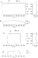
Figures 7 and 8 exemplify possible characteristics of the light intensity distribution (Intensity - scale of the ordinate ofFigure 8 ) obtainable throughlenses 102 such as those illustrated above. - In particular, the diagrams of
Figures 7 and 8 illustrate the characteristics of the light radiation distribution obtainable with a lens 102 (assuming reference togenerators 100, such as LEDs, having - at their output - a substantially Lambertian light radiation distribution), which can present two side peaks in two orthogonal planes (L=0° and L=90°, corresponding in practice to the cross-sectional planes ofFigures 5 and 6 ). - The possible effect of the use of such a distribution is exemplified in
Figures 9 and 10 . -
Figure 9 exemplifies possible illuminance trends (in Lux) according to two orthogonal directions X and Y in an ideal plane S' placed at the same distance of the plane S but assuming to operate "out" from a box like thebox 10 ofFigures 1 and 2 , i.e. assuming that thewalls - As can be seen by looking at the diagrams of parts b) and c) - referring, respectively, to the X and Y dimensions of the ideal plane S' represented in part a) of the same figure - the aforesaid intensity distribution is not uniform in either of the directions X, Y.
-
Figure 10 instead illustrates the effect achievable on the plane S using a light intensity distribution as can be achieved with a lens 102 (assuming, for simplicity, reference to a single lighting distribution positioned at the center of theupper wall 12 of the box 10) if also taking into account the reflective effect of theside walls - As appreciable in comparison with
Figure 9 , the overall result on the reference plane S, represented in part a) ofFigure 10 , is markedly more uniform, both in the direction of the X axis (part b) ofFigure 10 ), and in the direction of the Y axis (part c) ofFigure 10 ). - The comparison between, on one hand,
Figures 7 and 8 and, on the other hand,Figures 9 and 10 (especially the latter) may seem at first sight counter-intuitive: considering the diagrams ofFigures 7 and 8 in fact, illuminance peaks would be expected on the plane S ofFigure 10 at the angles where the intensity assumes the maximum value. - However, for the relation that links the light intensity I(θ) with the illuminance E, the latter is scaled with the square of the distance between the source and the illuminated element on the plane S (distance that varies rapidly as the angle increases), and then projected onto the element area.
- As illustrated in greater detail below, intensity (I(θ)) (function of the angle θ with respect to the axis X102) and projected illuminance E are, in fact, linked by a relation of the type:

- For a fixed height H between the illuminating device (e.g. lens + source) that emits the light intensity I(θ) and the element of the lighted plane along the same angle θ, the distance d can be expressed as:
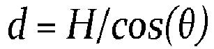

- Thus, between (projected) illuminance and intensity I(θ)I, there is a scale factor cos(θ)3 that varies from 1 to 0 very rapidly as a function of the angle θ.
- Therefore, in order to obtain a substantially uniform illuminance on the lighted plane S, to compensate for this effect, the intensity I(θ) is increased at least as rapidly, as a function of the angle, and this is possible thanks to the presence of side peaks of the type of those observable in the graphs of
Figures 7 and 8 . -
Figures 11 and subsequent figures illustrate possible adoptable criteria for choosing the configuration and/or the dimensioning of a lens such as thelens 102. - In particular,
Figures 11 to 13 refer to possible values of the emission angles of the light radiation starting from the radiation generator (for example LED 100 - angle qS) and at the output from thesurface 1022 of the lens 102 (angle qL). The aforesaid angles refer to the optical axis X102 already defined above. - In particular, the diagrams of
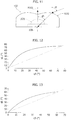
Figures 12 and 13 exemplify the dependence of the angle qL (ordinate scale) with respect to the input angle qS (abscissa scale), respectively: - in the longitudinal direction, i.e. the alignment direction of the
convex portions Figure 12 , and - in the transversal direction - diagram of
Figure 13 ) . - It is possible to observe that the overall behavior is - to a certain extent - similar to that described, for example, in
Figures 6 to 8 of the patent documentUS 7 348 723 B2 , already cited above. - However, unlike what was previously described in this earlier document, in the case considered here qL is always greater than qS, even when qS is near the optical axis (angles ≤ 5°): this applies both in the longitudinal direction and in the transverse direction.
- The observation of the diagrams of
Figures 12 and 13 also indicates the presence of a limit angle value (equal to about 75° in the longitudinal direction and about 60° in the transverse direction) in which this rule no longer applies, as the light radiation emitted from thegenerator 100 impacts on the side vertical walls of the lens (i.e. it no longer impacts the free-form output surface 1022). - One or more embodiments may be based on the recognition of the fact that creating, for example, by means of a lens, a flat illuminance field on a reference surface does not allow the desired result to be achieved if, at the same time, illuminating the side walls of the box is desired in such a way that, for example, the plants on the plane S receive correct illuminance even while they are growing, being located close to the walls of the box.
- In principle, one could think of designing a lens capable of uniformly illuminating a greater reference plane than the desired one. By proceeding in this way, parts of the light radiation at the most distant ends of the lighting field can actually arrive at the walls of the box. However, this solution does not allow the desired result to be achieved as the back-reflected light from the side walls on the plane S causes the illuminance on this plane to be non-uniform.
- Below, possible criteria can be used to define the characteristics of the
lens 102 in order to allow uniform illuminance of the reference plane (also) to be obtained when thelight radiation generators 100 and thelenses 102 are placed inside abox 10 provided withreflective side walls - The considerations expressed hereafter refer to a box such as the
box 10 exemplified inFigures 1 and 2 assuming that the plane S is at a distance H with respect to the upper wall where the light radiation sources are located (array 18). - The following analytical treatment refers (see
Figure 14 ) to one of the two halves in which thebox 10 may be ideally subdivided assuming that the other half of the box (not shown inFigure 14 ) exhibits specularly symmetrical behavior with respect to the vertical line on the left ofFigure 14 where the lighting source is assumed to be positioned (generator, for example LED, 100 and lens 102). - The light radiation coming from the
lens 102 follows two different paths, by propagating inside thebox 10. - A first path directly impacts a surface element ET of the reference plane S, while a second path impacts the side walls (141, 142, on the right of the
Figure 14 ) to be reflected backwards and impact the surface element ET on the reference plane S. - For simplicity, it can be assumed that the plane S is perfectly absorbent: this hypothesis is realistic because this plane is covered by the culture medium - for example soil for plants - and can, therefore, be considered an absorbing surface with a good approximation.
- The relation between the illuminance EW projected on a plane according to the intensity distribution at the angle θW can be expressed in the form:

lens 102 at the angle θW ,EW is the illuminance on the plane of the wall and dw is the distance between the source and the wall element. - The brilliance of a wall with Lambertian behavior lighted by a lighting source can be expressed as:

- In the simplified model considered here, the total illuminance on the element of the reference plane ET is given by the sum of the two illuminance components:

- The term EW̃ is generally quite complicated because it takes into account the fact that the incident light on the single receiving surface element (ET ) as back-reflected from the walls derives, in principle, from each small surface element of the wall (positioned at a height between 0 and H).
- Consequently, the light coming from the source that impacts on the side walls and is then back-reflected on the same receiving surface element ET is added to all possible angles θ̃W . The distance between the element ET and EW̃ is dW̃ :
Taking into account the relation between the reflectivity of the wall and the intensity that impacts the wall, Ĩ(θ̃W ) can be expressed in the form:
- Combining all the equations seen previously, the overall illuminance collected by the receiving surface element, ET , can be expressed as:


- Thanks to the relation between the angle θ̃W and the distance dW̃


- Therefore the total illuminance can be expressed as:

- Despite this simplified description, the equation of the total illuminance is still rather complicated to evaluate. It would, in fact, be desirable to have an expression that depends only on one angle (θ).
- In this regard it can be observed that the angles θ and θW are limited by the size of the box 10: it can be seen that, being,


- It is possible to derive the equation for the intensity distribution of the light source when uniform illumination of the reference plane is required without considering the presence of the walls.
- This relation can be easily derived from the expression seen above for ES , imposing it to be a constant:

- Solving with respect to I(θ) we obtain (see the dashed graph in
Figure 16 )

- This particular intensity distribution makes it possible to better understand why a lens that generates it would not be - in itself - usable in a case like the one considered here.
- In fact, if we also consider the simple condition in which only one element of the wall reflects the light towards the reference plane S, the total distribution of illuminance on the reference plane S could be expressed in the form:

Figure 15 (Normalized Illuminance) as a function of the angle θ, expressed in radians. - This figure is an exemplary diagram of the distribution of normalized illuminance (ordinate scale) on the reference plane, obtainable inside the
box 10 using an intensity distribution according to a constant illuminance outside the box. The diagram shows that the illuminance distribution increases as the edge of thebox 10 is gradually approached, due to the back-reflection of light from the walls. - Conversely, when a constant illuminance distribution on the reference plane S is required (independent of θ), the same relation suggests a possible choice for the intensity distribution starting from the
lens 102, that is:
- The diagram in
Figure 16 exemplifies possible trends in the distribution of Normalized Intensity as a function of the angle θ, expressed in radians and obtainable with a constant illuminance source outside the box 10 (dashed-line diagram) and inside the box 10 (continuous-line diagram). - By evaluating the term ES (θ) using this intensity distribution, it is possible to obtain the diagram indicated with a dashed line in
Figure 17 . - This diagram shows that, if you do not consider the box 10 (i.e. if you reason without taking into account the
side walls 141, 142), the illuminance distribution (Normalized Illuminance) as a function of the angle θ, expressed in radians, obtainable on the reference plane S is not flat but gradually decreases from the center towards the edge of the box. - On the other hand, if this intensity distribution is placed inside the box 10 (with the
side walls Figure 17 . - This figure illustrates (in ordinate) the illuminance distribution normalized in the reference plane S obtainable starting from a source like the one previously considered using the intensity distribution seen previously on the outside of the box (dashed-line diagram) compared with the normalized illuminance obtained when this intensity distribution is used inside the box 10 (continuous line diagram).
- The observation of the preceding diagrams and the analytical treatment previously carried out provide criteria for making the
lens 102 in such a way that the intensity distribution gradually increases as the light beam impacts the reference surface S between the central position (arranged perpendicularly below the surface of the lens 102) and the outer region limited by the side walls. This is compared to the distribution that allows a uniform illuminance field (flat) in the same region to be obtained. - The intervention law of this variation factor can be determined according to various parameters, such as, for example, the reflectivity of the walls.
- It will be appreciated, however, that the treatment provided previously is of a simplified nature, due to various aspects:
- it only considers the contribution of a single wall of the
box 10, when in reality there are contributions coming from all the walls of thebox 10, - it only considers the illuminance contribution of a single wall element kept fixed starting from a certain point onwards, when in reality there is a summing effect of all the elements of the same wall,
- it only considers a two-dimensional model, when in reality there are illuminance contributions from all the wall elements of each wall,
- it does not take into account the effects of the presence of several lenses (see for example
Figure 3 ) and of multiple reflections of the light on the various walls of thebox 10. - However, it has been verified that this simplified model also allows completely satisfactory results to be obtained.
- In addition to this, by creating the surfaces of the
lens 102 so as to best approximate the required theoretical intensity distribution, it is possible to obtain a lens conformation (such as the one illustrated inFigures 4 to 6 ) capable of providing a good degree of uniformity on the reference plane S for theentire array 18. - A lens such as the
lens 102 exemplified above has an asymmetric profile (if considered with reference to the cylindrical symmetry profile of traditional lenses). The optical power coming from such a lens has, however, a certain degree of symmetry with a radiation pattern of a certain type in one direction (for example, in the direction of the lens length, for example, the longitudinal alignment direction of the convexities 1022a, 1022b) and a different radiation pattern in a transverse direction (for example, in the direction perpendicular to the aforesaid longitudinal direction). - This fact can be appreciated, for example, by examining the distribution of light intensity coming from a single lens as exemplified in the diagrams of
Figures 7 and 8 . - In these figures, it can be seen that the intensity distribution in the longitudinal direction is represented in the dashed line, while the intensity distribution in the perpendicular direction is represented by the continuous curve.
- It is possible to see that achieving a uniformly illuminated surface within a box 10 (with the dimensions indicated above by way of example) can be facilitated by an intensity distribution increasing monotonically from the center (0°) towards side peaks having values of 75° (and 60°, respectively) and then decreasing monotonically towards higher angle values (for example 90°) above the peak.
- As for the possible distribution of the lighting sources (generators, for example,
LEDs 100 and lenses 102) in thearray 18, as already said previously, in one or more embodiments, thegenerators 100 may differ from each other by different parameters such as spectrum, flux value and radiation pattern. - In one or more embodiments it is possible to distribute
generators 100 with different colors/powers in a (pseudo)random fashion in anarray 18. However, this can make it more difficult to achieve complete color uniformity on the illuminated surface (plane S): it cannot be excluded that LEDs of the same color end up being accidentally grouped at a portion of the array. - In one or more embodiments it is possible to distribute the
generators 100 on the basis of a balanced sequence so as to facilitate obtaining uniformity of color and flux. - Assuming, by way of example, that LEDs of four different types are available, identified as LED1, LED2, LED3, LED4, these LEDs can be distributed in a linear array according to a law of the type...., LED3, LED2, LED1, LED4, LED3, LED2, LED1, LED4.. and so on.
- In one or more embodiments it is possible to adopt a uniform distribution for both the
generators 100 and thelenses 102 associated therewith, as exemplified inFigure 18 , with uniform spacing both of thegenerators 100 and of thelenses 102. - In one or more embodiments as exemplified in
Figure 19 , it is possible to envisage that, with uniformly-spacedlenses 102, thegenerators 100 are spaced in an uneven manner so that one or more of thegenerators 100 can be placed in an eccentric position with respect to therespective lens 102. - In this way, it is possible to implement "regulation" actions of the uniformity in terms of color and lighting according to the needs of application and use, without changing the shape of the lenses.
- In one or more embodiments as exemplified in
Figure 20 , similar results can be achieved by maintaining the mounting position of thelenses 102 centered with respect to thegenerators 100, but using an uneven spacing of the individual sources (generator 100-lens 102). - Considerations such as those exemplified with reference to
Figures 18 to 20 apply to both linear arrays and matrix arrays comprising several lines or rows. - Using multiple lines or rows (or possibly even several arrays), it is possible to further improve the uniformity effect by distributing the sources differently in the various rows/arrays according to certain color sequences or with the same sequence of colors offset from one row/array to another (for example, using the same sequence for different rows, but starting the sequence with a different color LED in each row from that of the adjacent row).
- One or more embodiments may possibly envisage the use of
different lenses 102 so as to be able to modify the radiation emission intensity profile, for example, by placing peak values at different values (for example, changing them from 75° to 50° or less) so as to increase the lighting power at particular spatial regions. In this case, it is possible to use one or more arrays to uniformly illuminate the surface S, but envisaging the presence of arrays intended to illuminate certain regions more intensely. - A solution of this type can be used, for example, when the
side walls box 10 are different from each other, for example, with a transparent or semi-transparent wall (for example, of glass or Plexiglas) so as to have a degree of reflectivity (even much) lower than that of the other walls. - In this case, it is possible to use
lenses 102 that concentrate the light intensity in the vicinity of these less-reflecting walls (for example a glazed wall). - The diagram of
Figure 21 refers, according to methods substantially similar to those ofFigure 10 , to the possibility of usingasymmetrical lens profiles 102, at least in one direction, so as to have, for example, a substantially uniform illuminance in the X direction of the reference plane S and a (less) uniform distribution in the direction of the Y axis in such a way that, for example, the portion of the plane S illustrated above in part a) ofFigure 21 is more intensely illuminated than the part shown below, where one can assume, for example, a semi-transparent wall such as a glass window is present). - One or more embodiments may provide, instead of the reduction (for example from 75° to 50°), an increase (for example from 75° to 80° or greater) of the angle value in which there is a peak of emission intensity, so as to also partially illuminate the walls of the
box 10. - A solution of this type can be adopted, for example, to concentrate the lighting on plants at a more advanced stage of growth.
- In one or more embodiments, the
lenses 102 may have not only an optical function but also a mechanical function. - For example, a lens such as the
lens 102 exemplified above may have grooves (e.g., grooves, which surround the input surface 1021) for positioning sealing elements or for accommodating electrical components (e.g., electronic components such as SMD components) capable of cooperating with thegenerators 100. These can be components such as resistors, integrated circuits, and so on. - In this way, it is possible to also use the body of the
lens 102 as a covering element of the lighting device (fixture), since it is thus possible to reduce the number of components to be mounted together and also increase the efficiency of light emission. - In one or more embodiments it is also possible to apply an (inner or outer) coating on the
lenses 102 to increase efficiency (which could be, for example, an anti-reflective coating) or to strengthen the surface, making it less sensitive to scratching, attack with solvents and so on. - In one or more embodiments, the
lens 102 may also take on a protection task against the penetration of external agents (for example, with a degree of IP protection) . - An installation (e.g. 10) according to one or more embodiments may comprise:
- a lighting space between a lighted plane (e.g. S) and a lighting plane (e.g. 12) parallel to the lighted plane with side walls (e.g. 141, 142), which are at least partly light-reflective,
- a set (e.g. 18) of light radiation sources (e.g. 100, 102) arranged centrally relative to the lighting plane and projecting (emitting) light radiation towards the lighted plane in the direction of a (main) radiation emission axis (X102),
- In other words, in one or more embodiments, the light radiation of the light radiation sources may have a illuminance distribution projected towards the plane S so that, if - no - side walls are present (such as the
walls 141 and 142), there would be a non-uniform illuminance distribution on the lighted plane S, with a decreasing trend as a function of the angle θ with respect to the main emission direction. In one or more embodiments, the presence ofwalls 142, 143, which reflect the radiation towards the plane S, is instead such as to facilitate obtaining - at the lighted plane (note S) - a uniform illuminance. - In one or more embodiments, this result is achievable with an intensity distribution I(θ) that is non-uniform and gradually increases as a function of the angle (θ), which can be expressed according to a relation like the one discussed above by way of example

- In this way, in one or more embodiments, it is possible to compensate the contribution of the reflection of the radiation on the side walls (141, 142) facilitating a uniform illuminance E(θ) at the lighted plane (S).
- In one or more embodiments, the light radiation sources in said set may comprise:
- a light radiation generator (e.g. 100), optionally with LEDs, and
- a lens (102) (see, for example, qS, qL in
Figures 11 to 13 ) for shaping the intensity pattern of the light radiation emitted by the light radiation generator (100). - In one or more embodiments the lens may include an optical axis (e.g. X102), a light radiation input surface (e.g. 1021) facing the light radiation generator and a light radiation output surface (e.g. 1022) facing the lighted plane, wherein the radiation leaving the output surface of the lens forms, with respect to the optical axis, an output angle (e.g. qL) greater than the input angle (e.g. qS) formed, with respect to the optical axis, by radiation entering the input surface of the lens.
- In one or more embodiments, the lens may include a dome-shaped light radiation input surface and a light radiation output surface including a pair of convex portions (e.g. 1022a, 1022b) with a concavity (e.g. 1023) therebetween, the concavity aligned with the dome-shaped input surface.
- In one or more embodiments the concavity between the convex portions may present a median plane with the specularly convex portions symmetric with respect to said median plane.
- In one or more embodiments, the lens may be mechanically coupled to the light radiation generator, optionally with an interposed seal and/or associated electrical components.
- In one or more embodiments, the set of light radiation sources may comprise at least one linear array of light radiation sources.
- In one or more embodiments, the convex portions of the output surface of the lens can be transversely aligned relative to the direction of extension of the at least one linear array of light radiation sources.
- One or more embodiments may comprise a parallelepiped lighting space with a first (e.g., 141) and a second (e.g., 142) pair of mutually opposite side walls.
- In one or more embodiments, at least one linear array may extend parallelly to one of the pairs of side walls.
- In one or more embodiments, the set of light radiation sources may comprise equally spaced sources (see, for example,
Figure 18 ). - In one or more embodiments, the set of light radiation sources may comprise light radiation sources that differ from one another by at least one of the following:
- the emission spectrum,
- the value of the emitted light flux,
- the light emission pattern,
- the spacing relative to neighboring light radiations sources in the set.
- In one or more embodiments:
- at least one of the side walls has a light reflectivity lower than the other side walls, and
- said non-uniform projected illuminance distribution may decrease non-symmetrically with a smaller decrease at the at least one wall with lower light reflectivity (see e.g.
Figure 21 ). - One or more embodiments may comprise a culture medium filling for vegetables (e.g. P in
Figure 2 ), the surface of the culture medium defining the lighted plane. - A method according to one or more embodiments may comprise:
- providing a lighting space between a lighted plane and a lighting plane parallel to the lighted plane with side walls, which are at least partly light-reflective,
- arranging a set of light radiation sources centrally relative to the lighting plane, which project light radiation towards the lighted plane in the direction of a (main) radiation emission axis,
- shaping (e.g. by means of the lenses 102) the distribution of the light radiation from the light radiation sources as an illuminance distribution projected towards the lighted plane, which is non-uniform and gradually decreasing as a function of the angle (θ) relative to said radiation emission axis (X102), the reflection of radiation on the side walls (141, 142) facilitates uniform illuminance at the lighted plane (S).
- In one or more embodiments of this method, the light radiation of the light radiation sources may have an intensity distribution that is non-uniform and gradually increases as a function of the angle relative to said radiation emission axis.
- Without prejudice to the underlying principles of the invention, the details of construction and the embodiments may vary, even significantly, with respect to those illustrated here, purely by way of non-limiting example, without departing from the scope of the invention.
- The scope of protection is defined by the attached claims.
LIST OF REFERENCE SIGNS Installation 10 Lighted plane S Lighting plane 12 Side walls 141, 142 Set of sources 18 Radiation emission axis X102 Angle θ Light radiation generator 100 Lens 102 Input surface 1021 Output surface 1022 Output angle qL Input angle qS Convex portions 1022a, 1022b Concavity 1023
Claims (17)
- An installation (10) including:- a lighting space between a lighted plane (S) and a lighting plane (12) parallel to the lighted plane (S) with side walls (141, 142) that are at least partly light-reflective,- a set (18) of light radiation sources (100, 102) arranged centrally relative to the lighting plane (12) and projecting light radiation towards the lighted plane (S) in the direction of a radiation emission axis (X102),wherein the light radiation from the light radiation sources (100, 102) has a distribution of illuminance projected towards the lighted plane (S) that is non-uniform and gradually decreases as a function of the angle (θ) relative to said radiation emission axis (X102), wherein the reflection of the radiation on the side walls (141, 142) facilitates uniform illuminance at the lighted plane (S).
- The installation (10) of claim 1, wherein the light radiation from the light radiation sources (100, 102) has an intensity distribution, I(θ), which is non-uniform and gradually increases as a function of the angle (θ) relative to said radiation emission axis (X102).
- The installation (10) of claim 1 or claim 2, wherein the light radiation sources in said set (18) include:- a light radiation generator (100), preferably an LED generator,- a lens (102) shaping (qS, qL) the intensity pattern of the light radiation emitted by the light radiation generator (100).
- The installation (10) of claim 3, wherein the lens includes an optical axis (X102), a light radiation input surface (1021) facing the light radiation generator (100) and a light radiation output surface (1022) facing the lighted plane (S), wherein radiation leaving the output surface (1022) of the lens (102) forms, with respect to the optical axis (X102), an output angle (qL) greater than the input angle (qS) formed, with respect to the optical axis (X102), by light radiation entering the input surface (1021) of the lens (102).
- The installation (10) of claim 3 or claim 4, wherein the lens (102) includes a dome-shaped light radiation input surface (1021) and a light radiation output surface (1022) including a pair of convex portions (1022a, 1022b) with a concavity (1023) therebetween, the concavity (1023) being aligned with the dome-shaped input surface (1021).
- The installation (10) of claim 5, wherein the concavity (1023) between the convex portions (1022a, 1022b) includes a median plane with the convex portions (1022a, 1022b) specularly symmetrical with respect to said median plane.
- The installation (10) of any of claims 3 to 6, wherein the lens (102) is mechanically coupled to the light radiation generator (100), preferably with a seal therebetween and/or electrical components associated therewith.
- The installation (10) of any of the previous claims, wherein the set (18) of light radiation sources includes at least one linear array of light radiation sources (101, 102).
- The installation (10) of claim 8, in combination with either one of claims 5 and 6, wherein the convex portions (1022a, 1022b) of the output surface (1022) of the lens are transversally aligned relative to the direction of extension of the at least one linear array of light radiation sources (101, 102).
- The installation (10) of any of the previous claims, including a parallelepiped lighting space with a first (141) and a second (142) pair of mutually opposite side walls (141, 142).
- The installation (10) of claim 10, in combination with either one of claims 8 and 9, wherein the at least one linear array extends parallelly to one (142) of the pairs of side walls (141, 142).
- The installation (10) of any of the previous claims, wherein the set (18) of light radiation sources includes sources (100, 102) equally spaced therebetween.
- The installation (10) of any of the previous claims, wherein the set (18) of light radiation sources includes sources (100, 102) that differ from each other by at least one of the following:- the emission spectrum,- the value of the emitted light flux,- the light emission pattern,- the spacing relative to neighboring light radiations sources in the set.
- The installation (10) of any of the previous claims, wherein:- at least one of the side walls (141, 142) has a light reflectivity lower than the other side walls, and- said non-uniform projected illuminance distribution decreases non-symmetrically with a smaller decrease at the at least one wall with lower light reflectivity.
- The installation (10) of any of the previous claims, including a filling of growth medium for vegetables (P), the surface of the growth medium defining the lighted plane (S).
- A method including:- providing a lighting space between a lighted plane (S) and a lighting plane (12) parallel to the lighted plane (S) with side walls (141, 142) that are at least partly light-reflective,- arranging a set (18) of light radiation sources (100, 102) centrally relative to the lighting plane (12), which project light radiation towards the lighted plane (S) in the direction of a radiation emission axis (X102),- shaping (102) the distribution of light radiation from the light radiation sources (100, 102) as a distribution of illuminance projected towards the lighted plane (S), which is non-uniform and gradually decreasing as a function of the angle (θ) relative to said radiation emission axis (X102), wherein the reflection of radiation on the side walls (141, 142) facilitates uniform illuminance at the lighted plane (S) .
- The method of claim 16, wherein the light radiation from the light radiation sources (100, 102) has an intensity distribution, I(θ), which is non-uniform and gradually increasing as a function of the angle (θ) relative to said radiation emission axis (X102).
Applications Claiming Priority (1)
| Application Number | Priority Date | Filing Date | Title |
|---|---|---|---|
| IT201700067055 | 2017-06-16 |
Publications (1)
| Publication Number | Publication Date |
|---|---|
| EP3414994A1 true EP3414994A1 (en) | 2018-12-19 |
Family
ID=60138840
Family Applications (1)
| Application Number | Title | Priority Date | Filing Date |
|---|---|---|---|
| EP18176332.7A Withdrawn EP3414994A1 (en) | 2017-06-16 | 2018-06-06 | A lighting installation and corresponding method |
Country Status (3)
| Country | Link |
|---|---|
| US (1) | US11337382B2 (en) |
| EP (1) | EP3414994A1 (en) |
| CN (1) | CN109140287B (en) |
Families Citing this family (8)
| Publication number | Priority date | Publication date | Assignee | Title |
|---|---|---|---|---|
| US11800835B2 (en) * | 2019-01-10 | 2023-10-31 | Verdant Lighting Technology, Inc. | Optical system for facilitating plant growth having non-uniform light density distribution |
| KR102828612B1 (en) * | 2019-02-18 | 2025-07-03 | 엘지전자 주식회사 | Plants cultivation apparatus |
| KR102899669B1 (en) | 2019-02-18 | 2025-12-12 | 엘지전자 주식회사 | Plants cultivation apparatus |
| KR102899887B1 (en) | 2019-02-18 | 2025-12-18 | 엘지전자 주식회사 | Plants cultivation apparatus |
| KR102828524B1 (en) | 2019-02-18 | 2025-07-03 | 엘지전자 주식회사 | Plants cultivation apparatus |
| KR102901777B1 (en) | 2019-02-18 | 2025-12-19 | 엘지전자 주식회사 | Plants cultivation apparatus |
| WO2020177003A1 (en) * | 2019-03-05 | 2020-09-10 | Ciencia Pura Spa | Flexible led lighting system for homogeneously lighting a horizontal plane and its use in cultivating plants in enclosed spaces such as greenhouses and plant propagation laboratories |
| KR102881586B1 (en) * | 2019-11-01 | 2025-11-06 | 엘지전자 주식회사 | plants cultivation apparatus |
Citations (4)
| Publication number | Priority date | Publication date | Assignee | Title |
|---|---|---|---|---|
| US20090225543A1 (en) * | 2008-03-05 | 2009-09-10 | Cree, Inc. | Optical system for batwing distribution |
| US20120198762A1 (en) * | 2011-02-04 | 2012-08-09 | Ricky Lee | Spectural specific horticulture apparatus |
| WO2016037950A1 (en) * | 2014-09-08 | 2016-03-17 | Philips Lighting Holding B.V. | Extruded channel plate as basis for integrated functions |
| US20170094914A1 (en) * | 2015-10-05 | 2017-04-06 | Carl Paquette | Plant Growing Apparatus |
Family Cites Families (28)
| Publication number | Priority date | Publication date | Assignee | Title |
|---|---|---|---|---|
| DE3602035A1 (en) * | 1985-01-31 | 1986-08-07 | Mitsubishi Denki K.K., Tokio/Tokyo | System for cultivating and growing plants |
| AU5798399A (en) | 1998-08-31 | 2000-03-21 | Halliburton Energy Services, Inc. | Force-balanced roller-cone bits, systems, drilling methods, and design methods |
| EP1498572A3 (en) | 1998-08-31 | 2006-04-12 | Halliburton Energy Services, Inc. | Roller-cone bits, systems, drilling methods, and design methods with optimization of tooth orientation |
| US7220018B2 (en) | 2003-12-15 | 2007-05-22 | Orbital Technologies, Inc. | Marine LED lighting system and method |
| JP3875247B2 (en) * | 2004-09-27 | 2007-01-31 | 株式会社エンプラス | Light emitting device, surface light source device, display device, and light flux controlling member |
| US20080148630A1 (en) * | 2006-12-20 | 2008-06-26 | Institute For Technology Development | Methods and systems for growing plants using diffuse scattering illumination |
| CN101178515A (en) * | 2007-12-10 | 2008-05-14 | 清华大学 | Light-emitting diode-based direct active dynamic backlight structure |
| CN201335319Y (en) * | 2008-12-25 | 2009-10-28 | 创研光电股份有限公司 | Optical lens and light emitting diode lighting device thereof |
| CN101836566A (en) * | 2009-03-18 | 2010-09-22 | 光宝科技股份有限公司 | Solar greenhouse structure and thin-film solar cell module thereof |
| US8070326B2 (en) * | 2010-01-07 | 2011-12-06 | Osram Sylvania Inc. | Free-form lens design to apodize illuminance distribution |
| CN102297382B (en) | 2010-06-25 | 2013-01-02 | 旭丽电子(广州)有限公司 | LED (light emitting diode) lens |
| TW201238473A (en) * | 2011-02-25 | 2012-10-01 | Illumitex Inc | Plant growth lighting device and method |
| CN202403119U (en) * | 2012-01-10 | 2012-08-29 | 厦门永华实业有限公司 | Led light intensity generator |
| US20150223409A1 (en) * | 2012-01-26 | 2015-08-13 | Mansur Abahusayn | Desalination greenhouse |
| KR101337503B1 (en) * | 2012-05-31 | 2013-12-06 | 한국광기술원 | Led package for agriculture and stockbreeding and system for controlling lighting using the same |
| WO2014031877A2 (en) * | 2012-08-22 | 2014-02-27 | Seoul Semiconductor Co., Ltd. | Illumination lens for led backlights |
| CN103609353A (en) * | 2013-11-13 | 2014-03-05 | 福建农林大学 | Uniform-light-distribution plant cultivation method and cultivation box |
| CN204201774U (en) * | 2014-11-03 | 2015-03-11 | 济南坤锐光学科技有限公司 | High-power integrated encapsulation LED illuminance uniformity plant growth lamp lens |
| TWM507641U (en) * | 2015-03-10 | 2015-09-01 | Chunghwa Picture Tubes Ltd | Plant growth device |
| ITUB20152355A1 (en) | 2015-07-21 | 2017-01-21 | Osram Spa | LIGHTING DEVICE, FOR EXAMPLE FOR GREENHOUSE LIGHTING, AND CORRESPONDING TO USE |
| ITUB20154156A1 (en) | 2015-10-06 | 2017-04-06 | Osram Spa | LIGHTING SYSTEM AND ITS PROCEDURE |
| KR101619461B1 (en) * | 2015-11-02 | 2016-05-10 | 김영원 | led apparatus for raising seeding |
| CN205124549U (en) * | 2015-11-11 | 2016-04-06 | 彭文煌 | Plant growing equipment that provides different shades of light |
| CN205454938U (en) * | 2016-02-02 | 2016-08-17 | 闫术刚 | Greenhouse |
| CN105815224A (en) * | 2016-04-29 | 2016-08-03 | 河南农业大学 | LED illumination system for tissue culture frame |
| CN205979386U (en) * | 2016-08-15 | 2017-02-22 | 华南理工大学 | Plant LED light filling lamp cultivated in a pot |
| CN106538292A (en) * | 2016-10-30 | 2017-03-29 | 成都奥能普科技有限公司 | A kind of interior nutrient source agricultural planting facility with pyramid energy |
| CN106545788B (en) * | 2016-11-24 | 2023-06-02 | 中国科学技术大学先进技术研究院 | High evenness light matter is than adjustable vegetation lamp |
-
2018
- 2018-06-06 EP EP18176332.7A patent/EP3414994A1/en not_active Withdrawn
- 2018-06-14 CN CN201810614135.5A patent/CN109140287B/en active Active
- 2018-06-14 US US16/008,134 patent/US11337382B2/en active Active
Patent Citations (4)
| Publication number | Priority date | Publication date | Assignee | Title |
|---|---|---|---|---|
| US20090225543A1 (en) * | 2008-03-05 | 2009-09-10 | Cree, Inc. | Optical system for batwing distribution |
| US20120198762A1 (en) * | 2011-02-04 | 2012-08-09 | Ricky Lee | Spectural specific horticulture apparatus |
| WO2016037950A1 (en) * | 2014-09-08 | 2016-03-17 | Philips Lighting Holding B.V. | Extruded channel plate as basis for integrated functions |
| US20170094914A1 (en) * | 2015-10-05 | 2017-04-06 | Carl Paquette | Plant Growing Apparatus |
Also Published As
| Publication number | Publication date |
|---|---|
| CN109140287A (en) | 2019-01-04 |
| CN109140287B (en) | 2022-06-24 |
| US20180363884A1 (en) | 2018-12-20 |
| US11337382B2 (en) | 2022-05-24 |
Similar Documents
| Publication | Publication Date | Title |
|---|---|---|
| US11337382B2 (en) | Lighting installation and corresponding method | |
| KR102255641B1 (en) | Large-area light sources and large-area lighting fixtures | |
| US20220228724A1 (en) | Plant growth lighting systems | |
| US9135837B2 (en) | Illumination assembly having multiple reflective cavities each with a single emitter | |
| ES2905638T3 (en) | Dual surface collimator and 3D electronic display employing network-based backlight using this collimator | |
| US10837619B2 (en) | Optical system for multi-emitter LED-based lighting devices | |
| US20160195243A1 (en) | Optical system for producing uniform illumination | |
| TW201629555A (en) | Diffraction grating-based backlighting having controlled diffractive coupling efficiency | |
| KR20130082084A (en) | Planar light source device and illumination apparatus | |
| JP2017525115A (en) | Multi-beam diffraction grating based color backlighting | |
| US20200053854A1 (en) | Tunable led light array for horticulture | |
| EP3589885B1 (en) | Sunlight-based large area light source and large area luminaire | |
| EP2122238A1 (en) | Lighting device comprising at least one led | |
| RU2013115918A (en) | LIGHTING DEVICE | |
| JP2022512856A (en) | Multi-view display and method | |
| US20170192154A1 (en) | Plant growth lighting system | |
| US20210109332A1 (en) | Optical system for an led wash luminaire | |
| US11946639B2 (en) | Lighting device | |
| JP7084404B2 (en) | Light guide with patterned ink | |
| US11266076B2 (en) | Lighting device and a method of distributing light radiation sources | |
| CN217382673U (en) | Wide-range lighting device suitable for animals and plants | |
| JP2012165877A (en) | Shelf-plate illumination device and showcase with the shelf-plate illumination device | |
| KR101643978B1 (en) | Lens optical system for light distribution control of square | |
| US20140321158A1 (en) | Light source module | |
| JP2016136879A (en) | Plant cultivation shelf |
Legal Events
| Date | Code | Title | Description |
|---|---|---|---|
| PUAI | Public reference made under article 153(3) epc to a published international application that has entered the european phase |
Free format text: ORIGINAL CODE: 0009012 |
|
| STAA | Information on the status of an ep patent application or granted ep patent |
Free format text: STATUS: THE APPLICATION HAS BEEN PUBLISHED |
|
| AK | Designated contracting states |
Kind code of ref document: A1 Designated state(s): AL AT BE BG CH CY CZ DE DK EE ES FI FR GB GR HR HU IE IS IT LI LT LU LV MC MK MT NL NO PL PT RO RS SE SI SK SM TR |
|
| AX | Request for extension of the european patent |
Extension state: BA ME |
|
| STAA | Information on the status of an ep patent application or granted ep patent |
Free format text: STATUS: REQUEST FOR EXAMINATION WAS MADE |
|
| 17P | Request for examination filed |
Effective date: 20190516 |
|
| RBV | Designated contracting states (corrected) |
Designated state(s): AL AT BE BG CH CY CZ DE DK EE ES FI FR GB GR HR HU IE IS IT LI LT LU LV MC MK MT NL NO PL PT RO RS SE SI SK SM TR |
|
| RAP1 | Party data changed (applicant data changed or rights of an application transferred) |
Owner name: OSRAM S.P.A. - SOCIETA' RIUNITE OSRAM EDISON CLERICI Owner name: OSRAM GMBH |
|
| RAP3 | Party data changed (applicant data changed or rights of an application transferred) |
Owner name: OSRAM GMBH Owner name: OSRAM S.P.A. - SOCIETA' RIUNITE OSRAM EDISON CLERICI |
|
| STAA | Information on the status of an ep patent application or granted ep patent |
Free format text: STATUS: EXAMINATION IS IN PROGRESS |
|
| 17Q | First examination report despatched |
Effective date: 20220727 |
|
| RAP1 | Party data changed (applicant data changed or rights of an application transferred) |
Owner name: FLUENCE BIOENGINEERING, INC. |
|
| STAA | Information on the status of an ep patent application or granted ep patent |
Free format text: STATUS: THE APPLICATION IS DEEMED TO BE WITHDRAWN |
|
| 18D | Application deemed to be withdrawn |
Effective date: 20250103 |