EP3414811B1 - Control of power system using distributed impedance injection modules and actuator devices within the power grid - Google Patents
Control of power system using distributed impedance injection modules and actuator devices within the power grid Download PDFInfo
- Publication number
- EP3414811B1 EP3414811B1 EP17750918.9A EP17750918A EP3414811B1 EP 3414811 B1 EP3414811 B1 EP 3414811B1 EP 17750918 A EP17750918 A EP 17750918A EP 3414811 B1 EP3414811 B1 EP 3414811B1
- Authority
- EP
- European Patent Office
- Prior art keywords
- speed communication
- control
- high voltage
- distributed
- power grid
- Prior art date
- Legal status (The legal status is an assumption and is not a legal conclusion. Google has not performed a legal analysis and makes no representation as to the accuracy of the status listed.)
- Active
Links
Images




Classifications
-
- H—ELECTRICITY
- H02—GENERATION; CONVERSION OR DISTRIBUTION OF ELECTRIC POWER
- H02J—ELECTRIC POWER NETWORKS; CIRCUIT ARRANGEMENTS OR SYSTEMS FOR SUPPLYING OR DISTRIBUTING ELECTRIC POWER; SYSTEMS FOR STORING ELECTRIC ENERGY
- H02J3/00—Circuit arrangements for AC mains or AC distribution networks
- H02J3/04—Arrangements for connecting networks of the same frequency but supplied from different sources
- H02J3/06—Controlling the transfer of power between connected networks; Controlling load sharing between connected networks
-
- G—PHYSICS
- G05—CONTROLLING; REGULATING
- G05B—CONTROL OR REGULATING SYSTEMS IN GENERAL; FUNCTIONAL ELEMENTS OF SUCH SYSTEMS; MONITORING OR TESTING ARRANGEMENTS FOR SUCH SYSTEMS OR ELEMENTS
- G05B15/00—Systems controlled by a computer
- G05B15/02—Systems controlled by a computer electric
-
- H—ELECTRICITY
- H02—GENERATION; CONVERSION OR DISTRIBUTION OF ELECTRIC POWER
- H02J—ELECTRIC POWER NETWORKS; CIRCUIT ARRANGEMENTS OR SYSTEMS FOR SUPPLYING OR DISTRIBUTING ELECTRIC POWER; SYSTEMS FOR STORING ELECTRIC ENERGY
- H02J13/00—Circuit arrangements for providing remote monitoring or remote control of equipment in a power distribution network
-
- H—ELECTRICITY
- H02—GENERATION; CONVERSION OR DISTRIBUTION OF ELECTRIC POWER
- H02J—ELECTRIC POWER NETWORKS; CIRCUIT ARRANGEMENTS OR SYSTEMS FOR SUPPLYING OR DISTRIBUTING ELECTRIC POWER; SYSTEMS FOR STORING ELECTRIC ENERGY
- H02J13/00—Circuit arrangements for providing remote monitoring or remote control of equipment in a power distribution network
- H02J13/12—Monitoring network conditions, e.g. electrical magnitudes or operational status
-
- H—ELECTRICITY
- H02—GENERATION; CONVERSION OR DISTRIBUTION OF ELECTRIC POWER
- H02J—ELECTRIC POWER NETWORKS; CIRCUIT ARRANGEMENTS OR SYSTEMS FOR SUPPLYING OR DISTRIBUTING ELECTRIC POWER; SYSTEMS FOR STORING ELECTRIC ENERGY
- H02J13/00—Circuit arrangements for providing remote monitoring or remote control of equipment in a power distribution network
- H02J13/13—Circuit arrangements for providing remote monitoring or remote control of equipment in a power distribution network characterised by the transmission of data to equipment in the power network
- H02J13/1321—Circuit arrangements for providing remote monitoring or remote control of equipment in a power distribution network characterised by the transmission of data to equipment in the power network using a wired telecommunication network or a data transmission bus
-
- H—ELECTRICITY
- H02—GENERATION; CONVERSION OR DISTRIBUTION OF ELECTRIC POWER
- H02J—ELECTRIC POWER NETWORKS; CIRCUIT ARRANGEMENTS OR SYSTEMS FOR SUPPLYING OR DISTRIBUTING ELECTRIC POWER; SYSTEMS FOR STORING ELECTRIC ENERGY
- H02J13/00—Circuit arrangements for providing remote monitoring or remote control of equipment in a power distribution network
- H02J13/18—Circuit arrangements for providing remote monitoring or remote control of equipment in a power distribution network characterised by the remotely-controlled equipment, e.g. converters or transformers
- H02J13/333—Circuit arrangements for providing remote monitoring or remote control of equipment in a power distribution network characterised by the remotely-controlled equipment, e.g. converters or transformers the equipment forming part of substations
-
- H—ELECTRICITY
- H02—GENERATION; CONVERSION OR DISTRIBUTION OF ELECTRIC POWER
- H02J—ELECTRIC POWER NETWORKS; CIRCUIT ARRANGEMENTS OR SYSTEMS FOR SUPPLYING OR DISTRIBUTING ELECTRIC POWER; SYSTEMS FOR STORING ELECTRIC ENERGY
- H02J3/00—Circuit arrangements for AC mains or AC distribution networks
-
- H—ELECTRICITY
- H02—GENERATION; CONVERSION OR DISTRIBUTION OF ELECTRIC POWER
- H02J—ELECTRIC POWER NETWORKS; CIRCUIT ARRANGEMENTS OR SYSTEMS FOR SUPPLYING OR DISTRIBUTING ELECTRIC POWER; SYSTEMS FOR STORING ELECTRIC ENERGY
- H02J3/00—Circuit arrangements for AC mains or AC distribution networks
- H02J3/001—Arrangements for handling faults or abnormalities, e.g. emergencies or contingencies
-
- H—ELECTRICITY
- H02—GENERATION; CONVERSION OR DISTRIBUTION OF ELECTRIC POWER
- H02J—ELECTRIC POWER NETWORKS; CIRCUIT ARRANGEMENTS OR SYSTEMS FOR SUPPLYING OR DISTRIBUTING ELECTRIC POWER; SYSTEMS FOR STORING ELECTRIC ENERGY
- H02J3/00—Circuit arrangements for AC mains or AC distribution networks
- H02J3/001—Arrangements for handling faults or abnormalities, e.g. emergencies or contingencies
- H02J3/0014—Arrangements for handling faults or abnormalities, e.g. emergencies or contingencies for preventing or reducing power oscillations in networks
-
- H—ELECTRICITY
- H02—GENERATION; CONVERSION OR DISTRIBUTION OF ELECTRIC POWER
- H02J—ELECTRIC POWER NETWORKS; CIRCUIT ARRANGEMENTS OR SYSTEMS FOR SUPPLYING OR DISTRIBUTING ELECTRIC POWER; SYSTEMS FOR STORING ELECTRIC ENERGY
- H02J3/00—Circuit arrangements for AC mains or AC distribution networks
- H02J3/18—Arrangements for adjusting, eliminating or compensating reactive power in networks
- H02J3/1821—Arrangements for adjusting, eliminating or compensating reactive power in networks using shunt compensators
- H02J3/1835—Arrangements for adjusting, eliminating or compensating reactive power in networks using shunt compensators with stepless control
-
- H—ELECTRICITY
- H02—GENERATION; CONVERSION OR DISTRIBUTION OF ELECTRIC POWER
- H02J—ELECTRIC POWER NETWORKS; CIRCUIT ARRANGEMENTS OR SYSTEMS FOR SUPPLYING OR DISTRIBUTING ELECTRIC POWER; SYSTEMS FOR STORING ELECTRIC ENERGY
- H02J3/00—Circuit arrangements for AC mains or AC distribution networks
- H02J3/38—Arrangements for feeding a single network from two or more generators or sources in parallel; Arrangements for feeding already energised networks from additional generators or sources in parallel
- H02J3/381—Dispersed generators
-
- Y—GENERAL TAGGING OF NEW TECHNOLOGICAL DEVELOPMENTS; GENERAL TAGGING OF CROSS-SECTIONAL TECHNOLOGIES SPANNING OVER SEVERAL SECTIONS OF THE IPC; TECHNICAL SUBJECTS COVERED BY FORMER USPC CROSS-REFERENCE ART COLLECTIONS [XRACs] AND DIGESTS
- Y02—TECHNOLOGIES OR APPLICATIONS FOR MITIGATION OR ADAPTATION AGAINST CLIMATE CHANGE
- Y02E—REDUCTION OF GREENHOUSE GAS [GHG] EMISSIONS, RELATED TO ENERGY GENERATION, TRANSMISSION OR DISTRIBUTION
- Y02E40/00—Technologies for an efficient electrical power generation, transmission or distribution
- Y02E40/30—Reactive power compensation
-
- Y—GENERAL TAGGING OF NEW TECHNOLOGICAL DEVELOPMENTS; GENERAL TAGGING OF CROSS-SECTIONAL TECHNOLOGIES SPANNING OVER SEVERAL SECTIONS OF THE IPC; TECHNICAL SUBJECTS COVERED BY FORMER USPC CROSS-REFERENCE ART COLLECTIONS [XRACs] AND DIGESTS
- Y02—TECHNOLOGIES OR APPLICATIONS FOR MITIGATION OR ADAPTATION AGAINST CLIMATE CHANGE
- Y02E—REDUCTION OF GREENHOUSE GAS [GHG] EMISSIONS, RELATED TO ENERGY GENERATION, TRANSMISSION OR DISTRIBUTION
- Y02E40/00—Technologies for an efficient electrical power generation, transmission or distribution
- Y02E40/70—Smart grids as climate change mitigation technology in the energy generation sector
-
- Y—GENERAL TAGGING OF NEW TECHNOLOGICAL DEVELOPMENTS; GENERAL TAGGING OF CROSS-SECTIONAL TECHNOLOGIES SPANNING OVER SEVERAL SECTIONS OF THE IPC; TECHNICAL SUBJECTS COVERED BY FORMER USPC CROSS-REFERENCE ART COLLECTIONS [XRACs] AND DIGESTS
- Y02—TECHNOLOGIES OR APPLICATIONS FOR MITIGATION OR ADAPTATION AGAINST CLIMATE CHANGE
- Y02E—REDUCTION OF GREENHOUSE GAS [GHG] EMISSIONS, RELATED TO ENERGY GENERATION, TRANSMISSION OR DISTRIBUTION
- Y02E60/00—Enabling technologies; Technologies with a potential or indirect contribution to GHG emissions mitigation
-
- Y—GENERAL TAGGING OF NEW TECHNOLOGICAL DEVELOPMENTS; GENERAL TAGGING OF CROSS-SECTIONAL TECHNOLOGIES SPANNING OVER SEVERAL SECTIONS OF THE IPC; TECHNICAL SUBJECTS COVERED BY FORMER USPC CROSS-REFERENCE ART COLLECTIONS [XRACs] AND DIGESTS
- Y02—TECHNOLOGIES OR APPLICATIONS FOR MITIGATION OR ADAPTATION AGAINST CLIMATE CHANGE
- Y02P—CLIMATE CHANGE MITIGATION TECHNOLOGIES IN THE PRODUCTION OR PROCESSING OF GOODS
- Y02P80/00—Climate change mitigation technologies for sector-wide applications
- Y02P80/10—Efficient use of energy, e.g. using compressed air or pressurized fluid as energy carrier
- Y02P80/14—District level solutions, i.e. local energy networks
-
- Y—GENERAL TAGGING OF NEW TECHNOLOGICAL DEVELOPMENTS; GENERAL TAGGING OF CROSS-SECTIONAL TECHNOLOGIES SPANNING OVER SEVERAL SECTIONS OF THE IPC; TECHNICAL SUBJECTS COVERED BY FORMER USPC CROSS-REFERENCE ART COLLECTIONS [XRACs] AND DIGESTS
- Y04—INFORMATION OR COMMUNICATION TECHNOLOGIES HAVING AN IMPACT ON OTHER TECHNOLOGY AREAS
- Y04S—SYSTEMS INTEGRATING TECHNOLOGIES RELATED TO POWER NETWORK OPERATION, COMMUNICATION OR INFORMATION TECHNOLOGIES FOR IMPROVING THE ELECTRICAL POWER GENERATION, TRANSMISSION, DISTRIBUTION, MANAGEMENT OR USAGE, i.e. SMART GRIDS
- Y04S10/00—Systems supporting electrical power generation, transmission or distribution
- Y04S10/12—Monitoring or controlling equipment for energy generation units, e.g. distributed energy generation [DER] or load-side generation
-
- Y—GENERAL TAGGING OF NEW TECHNOLOGICAL DEVELOPMENTS; GENERAL TAGGING OF CROSS-SECTIONAL TECHNOLOGIES SPANNING OVER SEVERAL SECTIONS OF THE IPC; TECHNICAL SUBJECTS COVERED BY FORMER USPC CROSS-REFERENCE ART COLLECTIONS [XRACs] AND DIGESTS
- Y04—INFORMATION OR COMMUNICATION TECHNOLOGIES HAVING AN IMPACT ON OTHER TECHNOLOGY AREAS
- Y04S—SYSTEMS INTEGRATING TECHNOLOGIES RELATED TO POWER NETWORK OPERATION, COMMUNICATION OR INFORMATION TECHNOLOGIES FOR IMPROVING THE ELECTRICAL POWER GENERATION, TRANSMISSION, DISTRIBUTION, MANAGEMENT OR USAGE, i.e. SMART GRIDS
- Y04S10/00—Systems supporting electrical power generation, transmission or distribution
- Y04S10/22—Flexible AC transmission systems [FACTS] or power factor or reactive power compensating or correcting units
-
- Y—GENERAL TAGGING OF NEW TECHNOLOGICAL DEVELOPMENTS; GENERAL TAGGING OF CROSS-SECTIONAL TECHNOLOGIES SPANNING OVER SEVERAL SECTIONS OF THE IPC; TECHNICAL SUBJECTS COVERED BY FORMER USPC CROSS-REFERENCE ART COLLECTIONS [XRACs] AND DIGESTS
- Y04—INFORMATION OR COMMUNICATION TECHNOLOGIES HAVING AN IMPACT ON OTHER TECHNOLOGY AREAS
- Y04S—SYSTEMS INTEGRATING TECHNOLOGIES RELATED TO POWER NETWORK OPERATION, COMMUNICATION OR INFORMATION TECHNOLOGIES FOR IMPROVING THE ELECTRICAL POWER GENERATION, TRANSMISSION, DISTRIBUTION, MANAGEMENT OR USAGE, i.e. SMART GRIDS
- Y04S10/00—Systems supporting electrical power generation, transmission or distribution
- Y04S10/30—State monitoring, e.g. fault, temperature monitoring, insulator monitoring, corona discharge
-
- Y—GENERAL TAGGING OF NEW TECHNOLOGICAL DEVELOPMENTS; GENERAL TAGGING OF CROSS-SECTIONAL TECHNOLOGIES SPANNING OVER SEVERAL SECTIONS OF THE IPC; TECHNICAL SUBJECTS COVERED BY FORMER USPC CROSS-REFERENCE ART COLLECTIONS [XRACs] AND DIGESTS
- Y04—INFORMATION OR COMMUNICATION TECHNOLOGIES HAVING AN IMPACT ON OTHER TECHNOLOGY AREAS
- Y04S—SYSTEMS INTEGRATING TECHNOLOGIES RELATED TO POWER NETWORK OPERATION, COMMUNICATION OR INFORMATION TECHNOLOGIES FOR IMPROVING THE ELECTRICAL POWER GENERATION, TRANSMISSION, DISTRIBUTION, MANAGEMENT OR USAGE, i.e. SMART GRIDS
- Y04S10/00—Systems supporting electrical power generation, transmission or distribution
- Y04S10/50—Systems or methods supporting the power network operation or management, involving a certain degree of interaction with the load-side end user applications
- Y04S10/52—Outage or fault management, e.g. fault detection or location
-
- Y—GENERAL TAGGING OF NEW TECHNOLOGICAL DEVELOPMENTS; GENERAL TAGGING OF CROSS-SECTIONAL TECHNOLOGIES SPANNING OVER SEVERAL SECTIONS OF THE IPC; TECHNICAL SUBJECTS COVERED BY FORMER USPC CROSS-REFERENCE ART COLLECTIONS [XRACs] AND DIGESTS
- Y04—INFORMATION OR COMMUNICATION TECHNOLOGIES HAVING AN IMPACT ON OTHER TECHNOLOGY AREAS
- Y04S—SYSTEMS INTEGRATING TECHNOLOGIES RELATED TO POWER NETWORK OPERATION, COMMUNICATION OR INFORMATION TECHNOLOGIES FOR IMPROVING THE ELECTRICAL POWER GENERATION, TRANSMISSION, DISTRIBUTION, MANAGEMENT OR USAGE, i.e. SMART GRIDS
- Y04S40/00—Systems for electrical power generation, transmission, distribution or end-user application management characterised by the use of communication or information technologies, or communication or information technology specific aspects supporting them
- Y04S40/12—Systems for electrical power generation, transmission, distribution or end-user application management characterised by the use of communication or information technologies, or communication or information technology specific aspects supporting them characterised by data transport means between the monitoring, controlling or managing units and monitored, controlled or operated electrical equipment
- Y04S40/124—Systems for electrical power generation, transmission, distribution or end-user application management characterised by the use of communication or information technologies, or communication or information technology specific aspects supporting them characterised by data transport means between the monitoring, controlling or managing units and monitored, controlled or operated electrical equipment using wired telecommunication networks or data transmission busses
Definitions
- the present invention relates to a high voltage power grid comprising high voltage transmission lines to transport power at high voltage from power generators to sub-stations or other distributed loads; a plurality of distributed impedance injection modules distributed along a plurality of segments of the high voltage transmission lines, each distributed impedance injection module being attached to a segment of the high voltage transmission lines and comprising an impedance injection module for injecting an impedance or equivalent voltage on the segment of the high voltage transmission line, and having a transmission line current measuring capability and an intelligent control capability; and a utility supervisory having a communication capability with the traditional large conventional power generation systems, and the sub-stations.
- the present invention relates to a method of controlling a high voltage power grid having high voltage transmission lines to transport power at high voltage from power generators to sub-stations or other distributed loads.
- EMS energy management system
- SCADA supervisory control and data acquisition
- DIIMs 102 are able to recognize changes in line current on the high-voltage lines, to which these are attached, and inject an appropriate inductive or capacitive impedance (alternately inject an equivalent voltage component) on to the line to locally balance the lines for power transfer.
- DIIMs distributed impedance injection modules
- HV high voltage
- Fig. 2 provides a more detailed block diagram 200 of distributed control of the HV power grid by the DIIMs 102 injecting an impedance or equivalent voltage on the segments of the high voltage power transmission line 108 on which these are suspended.
- the HV power transmission lines are themselves supported by towers 201.
- the substations 204 with generation capability 203 and loads 205 are also shown.
- the overall control of the transfer of power between the generators and loads is monitored and controlled by a utility supervisory 206 that communicates with the substations via normal communication channels 207 for monitoring and control.
- Fig. 2A is a block diagram 200A of the prior art implementation of controlling of the HV power grid using static synchronous series compensators (SSSCs) at the substations 204 that send information to the utility 206 and receive control instructions from the utility 206.
- the data and control are transferred over normal wired or wireless communication links 207 from SSSCs at the substations 204 to and from the utility 206.
- the generation capacity 203 and the distribution points 205 are connected to the HV power grid through the substations 204.
- the substations 204 are themselves enabled for power transfer over the high voltage (HV) transmission lines 108 suspended from the transmission towers 201.
- HV high voltage
- Fig. 2B shows a block diagram 200B for prior art ( U.S. Patent No. 8,401,709 ) local control of the HV power grid using existing resources proposed by the identified prior art Cherian applications and patents.
- These implementations are for unified power system control from the main generation 203 and distributed generators 213-1 and 213-2 (wind, solar, etc.) to distribution loads 205-1 to 205-3 connected by local power distribution lines 109, by local control modules 215-1 and 215-2.
- the control of the power system is proposed by controlling the existing assets at the substations 204-1 and 204-2 by using regional control modules 225 at the substations 204-1 and 204-2, using centralized computer programs at the enterprise control module 206, with generation and distribution connections to the HV power grid system.
- Such a system has been proposed by the Cherian applications, where data visualization programs 280 with smart grid control programs 285 use system modeling and simulation capability 290 at the enterprise 206.
- the proposed power system of control uses existing wireless area network (WAN) connections 230 to communicate with the various substations and for communication between the substations 204-1 and 204-2 and the enterprise control.
- WAN wireless area network
- FACTS alternating current transmission system
- SSSC static synchronous series compensators
- STATCOM static synchronous compensators
- UPFC unified power-flow controller
- IPFC interline power-flow controllers
- All these prior art implementations aid in maintaining and enhancing grid resiliency and power system stability through local VARs support and power-flow control of the prior art HV power grid.
- the new HV power grid and the total power system require different and faster capabilities for line balancing and for overcoming disturbances introduced by the distributed nature of power generation and load changes. It is essential to improve the response capability of the HV power grid control in order to take care of the changed nature of the HV power grid and the total power system and its characteristics.
- the problems to be addressed in this regard include balancing of lines when new distributed generation systems or loads come online and respond to disturbances.
- Due to the new nature of the HV power grid, such as responding to small signal stability issues, power oscillations damping (POD) and sub-synchronous resonance (SSR) damping on the HV power grid requires response at faster speeds to overcome more of these problems.
- the implementation of distributed energy storage capabilities that are coupled to the HV power grid will also have to be brought in and integrated to help in improving the stability of the HV power grid and the total power system as it is made more responsive to power changes on the HV power grid.
- US 2014/0371929 A1 discloses a power distribution system comprising intelligent electronic devices (IEDs) and a method for obtaining and refining an estimate of a source impedance value and/or creating a source impedance model based on measurements of source impedance modeling events in an electric power distribution system.
- the IEDs are connected to voltage measurement devices and other sensor devices, the voltage measurement devices being coupled to high voltage power lines.
- the IEDs may be in communication with circuit breakers and voltage regulators to control these devices.
- the IEDs are configured to monitor and communicate information, such as measured voltages and circuit breaker status, to communicate calculation results and setting and status information, and to issue control instructions to monitored equipment.
- US 2007/0124026 A1 discloses a conceptual distributed grid control including a "self-healing grid” concept and proposes to use available energy resources to facilitate improved electric grid operation, i.e. to use the infrastructure and the intelligent agents for communication within the infrastructure for efficient acquisition and distribution of energy.
- This object is accomplished according to the present invention by a high voltage power grid according to clam 1 and a method of controlling a high voltage power grid according to claim 10.
- the invention disclosed is generally directed at integrating and using the capabilities of the distributed impedance injection modules, the other actuator modules and the miscellaneous FACTS-coupled actuator devices for providing very high reliability, standardized active control capability that is FACTS-based, to the total power system.
- the total power system is typically comprised of conventional and distributed generation units, HV power transmission grid, power/ energy storage units, FACTS and non-FACTS control devices inside, at, or outside, the edge of the HV power grid and distributed load demand response units coupling the power distribution systems to the HV power grid.
- the integrated and hierarchical control capability proposed by the present invention disclosure using distributed impedance injection modules, other actuator modules and miscellaneous FACTS-coupled actuator devices is a general concept and can be applied with any distributed impedance injection modules, other actuator devices and the miscellaneous FACTS controlled actuator devices inter-linked in a hierarchical fashion using LINCs for transfer of data using the appropriate speed communication capability.
- the details of the invention disclosed are directed at using distributed impedance injection modules such as CDIIMs with local high-speed (speeds that enable sub-cyclic response) communication and control capabilities provided by the local intelligence centers (LINCs), in high-speed communication with other actuator devices and miscellaneous FACTS-coupled actuator devices at and outside the HV power transmission grid edge.
- distributed impedance injection modules such as CDIIMs with local high-speed (speeds that enable sub-cyclic response) communication and control capabilities provided by the local intelligence centers (LINCs), in high-speed communication with other actuator devices and miscellaneous FACTS-coupled actuator devices at and outside the HV power transmission grid edge.
- LINCs local intelligence centers
- Such an integrated local communication and control is able to provide very high reliability, integrated and hierarchically managed, and standardized active control capability to the total power system.
- the total power system as described previously, is comprised of distributed generation units, HV power transmission grid, energy storage units, other actuator devices and power distribution systems.
- the integrated control capability disclosed by the present invention using distributed impedance injection modules, other actuator devices and miscellaneous FACTS-coupled actuator devices are general concepts that are not meant to be limiting or be applicable using only a specific set of distributed impedance injection modules and other actuator devices.
- the invention can be implemented fully or partially using any appropriate distributed impedance injection modules, other actuator devices and miscellaneous FACTS-coupled actuator devices, that are within, at the edge, and outside the edge of the HV power grid as long as these have the capability for providing control and stability to the total power system including generation, transmission and distribution systems. In effect such proposed integrated control capability can be used effectively for transmission systems and distribution systems that include all micro-grid concepts and implementations.
- Sub-cyclic control has been identified as an essential need to have a stable and dynamic HV power grid and total power system.
- the HV power grid and the total power system should be able to handle issues of stability, intermittency, and transients that are inherent in the new distributed or localized renewable power generation and distributed loads that are being coupled to the HV power grid.
- CDIIM 301 or distributed impedance injection modules are made self-aware and have sufficient intelligence, computing capability, communication capability and control capability to respond locally to any sensed disturbance in a sub-cyclic timeframe.
- fast communication capability 303 has been established between the neighboring CDIIMs 301 and also the CDIIMs 301 and a local supervisory entity, the localized intelligence centers (LINCs) 302.
- LINCs localized intelligence centers
- Each LINC 302 provides communication and coordination of the operation of a plurality of CDIIM 301 covering a local area and also provides for high-speed communication 303 to other LINCs 302 when coordination and fast response is needed for disturbances that have the possibility of spreading to neighboring LINCs 302 controlled segments of the HV power grid.
- Communication 305 is also established from the LINCs 302 to and from the utility supervisory 206 using normal communication channels.
- Such communication 207 is also established to and from the substations 204 to the utility supervisory 206.
- These normal speed communication channels are used for monitoring, and supervisory control of the power grid, and the collection of data on power grid operations for simulation and optimization of the HV power grid operations.
- the generators 203 and loads 205 are shown connected to the sub-stations 204 which is no longer the case in the distributed generation power system that is currently evolving.
- the aim of the disclosed invention is to expand the operation of the distributed impedance injection modules CDIIMs, LINCs to optimize the operation of the total power system by providing standardized high-speed local control capability and high-speed local communication (sub-cyclic speeds) capability to the components and subsystems in the local segments of the HV transmission grid and the total power system.
- a number of FACTS-based monitoring and control capabilities and FACTS-coupled subsystems that influence the operation of the total power system from generation to distribution are being implemented within, at the edge and outside the edge of the total power system. It is the aim of the current invention to integrate the capabilities of all these subsystems locally with the CDIIMs and LINCs to provide a standardized local control capability.
- This standardized local control capability is established by inter-connected distributed impedance (or equivalent voltage) injection modules, LINCs, other actuator devices and miscellaneous FACTS-coupled actuator devices. All of these are enabled with high-speed communication capability and FACTS-based control capability to allow these components and subsystems of the total power system to react to disturbances and changes in power inputs and outputs to the total power system in a sub-cyclic manner at the local level.
- the distributed impedance injection modules CDIIMs are still used to recognize the disturbances and problems of the HV power grid at the local level and, through the connected LINCs, are able to coordinate with the other actuator devices and miscellaneous FACTS-coupled actuator devices locally to provide optimum responses to the disturbances and problems identified.
- the invention uses the built-in high-speed FACTS-based control capability and high-speed communication capability of the CDIIMs, currently used for fast recognition and correction of localized power flow imbalances or other instabilities or alternate conditions to also recognize any disturbances of the local connected sections of the HV power grid.
- the invention standardizes this type of control capability and communication capability and extends it to the coupled controllable devices that are the other actuator devices and the miscellaneous FACTS-coupled actuator devices, inside, at the edge and outside the edge of the high-voltage power grid to achieve an integrated and coordinated power flow control and disturbance recovery capability for the total power system.
- a plug-in version of the standardized high-speed communication module is also implemented, that convert the currently used self-aware intelligent distributed impedance (or equivalent voltage) injectors DIIMs 102 to distributed impedance injection modules CDIIMs 301.
- the CDIIMs 301 and LINCs 302 are able to coordinate the actions of these CDIIM and other actuator devices and the miscellaneous FACTS-coupled actuator devices to respond in a coordinated fashion at the local level and also on a total power system level to the needs of the total power system, increasing system stability and security.
- the CDIIMs, and other actuator devices and connected miscellaneous FACTS-coupled actuator devices such as distributed generation systems, energy storage systems, distributed load demand response (DR) devices with FACTS-based control etc. inside and outside the edge of the HV power grid, a smooth and optimum control for transfer of power from the generation to distribution is achieved.
- DR distributed load demand response
- the only way to overcome the variations and fluctuations on the total power system efficiently is to provide for local control of multiple points of the total power system concurrently, using the FACTS-based control and high-speed communication capabilities, built into the components and sub-systems of the total power system as per the present disclosed invention.
- the distributed impedance (or equivalent voltage) injection modules that have intelligence and self-awareness built in are able to update the reference settings for itself and other actuator devices and miscellaneous FACTS-coupled devices, locally connected to it through the LINCs.
- This is a key distinguishing feature of the current disclosed invention. This feature is applicable to both transmission as well as distribution systems that have the disclosed features.
- Another important feature of the total power system control proposed is the integration of distributed energy storage devices, that are inside or outside the grid edge, into the total power system enabling control in a distributed and hierarchical fashion as a part of the integrated and standardized control of the, systems and subsystems of the total power system as an embodiment of the invention.
- a cause of instability of the HV power grid, especially under disturbances and fault conditions is the sudden changes in the phase angle during power injection or load changes by the distributed generation and distributed loading.
- the propensity for instabilities and oscillations of the grid can be reduced or eliminated.
- This capability is further improved by the local control of the distribution provided by the Distributed Load demand response unit with FACTS-based control as per an embodiment of the invention.
- the main components of the system to achieve the above include:
- Fig. 4 shows a distributed impedance (or equivalent voltage) injection module (CDIIM 301) comprising a distributed impedance (or equivalent voltage) injection module 102 with an intelligent control capability 402 and high-speed communication capability 410, typically a high-speed transceiver, with connectivity through high speed link 303 to provide the sub-cyclic local response capability.
- CDIIM 301 distributed impedance (or equivalent voltage) injection module 102 with an intelligent control capability 402 and high-speed communication capability 410, typically a high-speed transceiver, with connectivity through high speed link 303 to provide the sub-cyclic local response capability.
- Fig. 5 is an exemplary block diagram of a FACTS monitoring and control module 500 that form other actuator devices that provide the capability for the FACTS electronic devices 501 connected to the total power system for controlling and analyzing its operation using the FACTS-based control capability 502 with high-speed communication capability 410, enabled through high speed link 303.
- Fig. 6 is a block diagram 600 showing the modification of the distributed generation capability 601, such as wind generation facility, solar generation facility, biogas generation facility, or other distributed power generation facility or facilities, coupled to the total power system using FACTS-based control capability 602.
- FACTS-based control 602 of power generation and input into the HV power grid with high-speed communication capability 410 and connected via a high spped link 303 for local communication to LINCs at the edge of the power grid for establishing integrated local control capability.
- This enable power input changes to be locally recognized and corrective action taken locally to prevent unwanted disturbances being introduced.
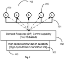
- Fig. 7 is a block diagram 700 of the distributed loads 205 that include the FACTS-based demand response (DR) control capability 702 and the high-speed communication capability 410 via high speed communication link 303, enabling load changes to be locally recognized and corrective actions initiated.
- DR demand response
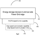
- Fig. 8 is a block diagram 800 showing the modifications that enable the energy storage devices 801 outside the edge of the power grid 300 coupled to the HV power grid.
- a controller 802 which in the case shown is a FACTS-based controller and a high-speed communication capability 410 with inter connections using high speed links 303 form part of the control capability for the total power system.
- Fig 9 is a block schematic 900 of the total power system as per the present invention, with two HV power grids 910 and 920 and associated distributed impedance injection modules 301, other actuator devices 500 that are enabled with distributed standardized control and communication capabilities.
- the current invention uses the capabilities established for sub-cyclic control and appropriate communication for all the distributed impedance injection modules 301, other actuator devices 500 and the miscellaneous FACTS-coupled devices, such as distributed generators 600, energy storage devices 800 etc. that are inside, at the edge and outside the edge of the power grid 300 to provide a distributed but integrated sub-cyclic control and response capability to the total power system 900. These enable optimization of the operation of the total power system 900 from generation to distribution.
- the CDIIM 301, LINCs 302, other actuator devices 500, the Energy Storage devices 800, and the distributed generation capabilities 600, as well as the distributed loads with DR capabilities 700 are all with control capability that is typically FACTS-based and are interconnected locally using the high-speed communication capability 410 provided by the high-speed communication links 303 associated with each of the devices as shown and described in Fig. 4 to Fig. 8 ., This communication capability is provided through the nearest LINC 302, shown in Fig. 9 , for localized communication and control supervision.
- the LINCs 302 are also interconnected with high-speed link connections 303 for high-speed inter-LINC communication between the neighboring local areas.
- the LINCs 302 are further connected to the utility supervisory 206 using communication connections 305 which may be slower than the high-speed connection links 303, to enable data transfer and overall supervisory control of the total power system.
- the control and communication capabilities of the total power system 900 implemented within, at the edge and outside the edge of power grid 300 are integrated using typically the FACTS-based control, and high-speed communication at each of the actuator modules, other actuator devices and miscellaneous FACTS-coupled actuator devices, and covers the total power system from generation to distribution.
- Such a system can provide optimized, dynamic, localized control of power flows from generators to loads by adjusting the generation outputs and line currents of the HV transmission grid based on system constraints and load requirements.
- the high-speed communication capabilities linking the CDIIM 301, LINCs 302, with the FACTS-coupled generators 600, DR-controlled loads 700, other actuator devices 500, and FACTS-coupled energy storage devices 800 provide a system-level capability for localized, intelligent and capable of sub-cyclic control of all connected subsystems and devices within the total power system 900.
- a typical example is when a distributed load comes online suddenly. Due to the inertia of the system, it takes time for the main generators to rev up and increase the supply current. The sudden increase in load can cause oscillations and droop in voltage on the HV Power grid and hence at the connected loads.
- the drop in voltage at the load and oscillations are sensed by the distributed monitoring and control facility of the CDIIM 301.
- the local CDIIM 301 respond to the oscillations by producing and injecting damping voltages on the line as has been described in the parent application.
- the monitoring and control capability of the CDIIM 301 linked, using high-speed communication links, directly or through LINCs 302 to other CDIIMs 301, to distributed local monitoring and control capability of FACTS-coupled generators 600, and FACTS-coupled storage devices 800.
- the control information / instructions provided from the CDIIMs 301 enable any locally connected FACTS-coupled energy storage devices 800 to be switched in to provide the necessary load current while the local distributed FACTS-coupled generators or the main conventional generators under supervisory control are reved up and brought online to cater to the load, thus enabling a much faster and smoother response to the additional load than possible with the current generator- distribution systems.
- the local monitoring and control capability at the distributed generators, load and the energy storage devices working together at the local level can resolve the problem of oscillations and sagging voltage at the distributed load.
- the information collected of the problem identified and the corrective action is also intimated to the supervisory utility 206 over the standard communication link 305.
- the supervisory utility 206 can then decide if any further action to re-balance the HV power grid and the total power system from generators to distribution is warranted for optimum operating efficiency of the total power system 900.
- a second example will be when a distributed generation capability such as wind or solar generation is brought online suddenly. Due to the low inertia associated with these generating systems they can be turned on and connected to the grid to pump energy into a stable operating HV power grid. This low inertia input can result in oscillations and unbalancing of the HV power grid and the total power system.
- the local sensing and monitoring capability of the CDIIM 301 senses the oscillations and the unbalanced HV power grid condition and the control element reacts by generating and injecting the necessary impedance/voltages to dampen the oscillations and to re-balance the HV power grid.
- the CDIIM 301 communicate over the high-speed links to the LINCs 302 to inform and provide control instructions to the FACTS control at the distributed FACTS-coupled generators 600 to control the rate of injection of power onto the HV power grid.
- the LINCs 302 also instruct the FACTS controllers at the FACTS-coupled energy storage devices 800 to enable storing of the excess energy pumped into the HV power grid till the HV power grid is brought back to equilibrium.
- the FACTS-coupled distributed generators 600 and the FACTS-coupled energy storage devices 800 all with high-speed communication capability, the HV power grid and the total power system stability is maintained even under these adverse conditions.
- the identified cause of HV power grid disturbance and the solution are also intimated to the supervisory utility 206 over the communication link 305 by the LINCs 302. The supervisory utility 206 can then decide if all the components of the total power system from generators to transmission to distribution need to be optimally re-balanced.
- the disclosed total power system 900 is hence able to respond optimally and locally at high-speed, (at sub-cyclic speed) to any of the disturbances on the total power system 900.
- the total power system 900 is also able to optimize its operations from the generation of power, transmission of power over high voltage transmission lines of the HV power grid, to the distribution of power needed at the appropriate voltage levels and phases.
- the disclosed invention provides also for monitoring and control of the general operation of the HV power grid and the total power system 900, for operations such as, but not limited to, line balancing, harmonic reduction or elimination, and monitoring and control of all other important system characteristics.
- the monitoring and control of the total power system 900 uses the hierarchical control capability established by the currently disclosed invention. All of the above are collectively referred to as "conditions"-conditions on the total power system including the high voltage transmission lines of the HV power grid in the claims to follow.
Landscapes
- Engineering & Computer Science (AREA)
- Power Engineering (AREA)
- General Engineering & Computer Science (AREA)
- Physics & Mathematics (AREA)
- General Physics & Mathematics (AREA)
- Automation & Control Theory (AREA)
- Remote Monitoring And Control Of Power-Distribution Networks (AREA)
- Supply And Distribution Of Alternating Current (AREA)
- Computer Networks & Wireless Communication (AREA)
Description
- The present invention relates to a high voltage power grid comprising high voltage transmission lines to transport power at high voltage from power generators to sub-stations or other distributed loads; a plurality of distributed impedance injection modules distributed along a plurality of segments of the high voltage transmission lines, each distributed impedance injection module being attached to a segment of the high voltage transmission lines and comprising an impedance injection module for injecting an impedance or equivalent voltage on the segment of the high voltage transmission line, and having a transmission line current measuring capability and an intelligent control capability; and a utility supervisory having a communication capability with the traditional large conventional power generation systems, and the sub-stations. Moreover, the present invention relates to a method of controlling a high voltage power grid having high voltage transmission lines to transport power at high voltage from power generators to sub-stations or other distributed loads.
- Most power utilities use energy management system (EMS) and supervisory control and data acquisition (SCADA) control systems to control HV power grid. These control systems connect and communicate between the power flow control units at the substations that are used to limit current flows or load imbalances over the HV power grid lines and provide interactive control of the power transmission on the HV power grid. Distributed and localized control of power flow, over the high voltage transmission lines using self-aware (with built-in capability to recognize problems / intelligence) distributed impedance (or equivalent voltage) injection modules (DIIMs) 102, has been proposed and is being implemented by the inventors of the current application as shown in
Fig. 1 andFig. 2 . TheseDIIMs 102 are able to recognize changes in line current on the high-voltage lines, to which these are attached, and inject an appropriate inductive or capacitive impedance (alternately inject an equivalent voltage component) on to the line to locally balance the lines for power transfer. - Referring to
Fig. 1 these self-aware (with built-in capability to recognize problems / intelligence) distributed impedance injection modules (DIIMs) 102 are distributed on segments of the high voltage (HV)transmission line 108, supported by, but insulated from, the towers 110, between the generation station 104 and the distribution points 106. These DIIMs 102 provide the capability of localized control of line current and line balancing for the local HV transmission line segment to which these are attached. -
Fig. 2 provides a more detailed block diagram 200 of distributed control of the HV power grid by theDIIMs 102 injecting an impedance or equivalent voltage on the segments of the high voltagepower transmission line 108 on which these are suspended. The HV power transmission lines are themselves supported bytowers 201. Thesubstations 204 withgeneration capability 203 andloads 205 are also shown. The overall control of the transfer of power between the generators and loads is monitored and controlled by a utility supervisory 206 that communicates with the substations vianormal communication channels 207 for monitoring and control. -
Fig. 2A is a block diagram 200A of the prior art implementation of controlling of the HV power grid using static synchronous series compensators (SSSCs) at thesubstations 204 that send information to theutility 206 and receive control instructions from theutility 206. The data and control are transferred over normal wired orwireless communication links 207 from SSSCs at thesubstations 204 to and from theutility 206. Thegeneration capacity 203 and thedistribution points 205 are connected to the HV power grid through thesubstations 204. Thesubstations 204 are themselves enabled for power transfer over the high voltage (HV)transmission lines 108 suspended from thetransmission towers 201. -
Fig. 2B shows a block diagram 200B for prior art (U.S. Patent No. 8,401,709 ) local control of the HV power grid using existing resources proposed by the identified prior art Cherian applications and patents. These implementations are for unified power system control from themain generation 203 and distributed generators 213-1 and 213-2 (wind, solar, etc.) to distribution loads 205-1 to 205-3 connected by localpower distribution lines 109, by local control modules 215-1 and 215-2. The control of the power system is proposed by controlling the existing assets at the substations 204-1 and 204-2 by using regional control modules 225 at the substations 204-1 and 204-2, using centralized computer programs at theenterprise control module 206, with generation and distribution connections to the HV power grid system. Such a system has been proposed by the Cherian applications, where data visualization programs 280 with smart grid control programs 285 use system modeling and simulation capability 290 at theenterprise 206. The proposed power system of control uses existing wireless area network (WAN)connections 230 to communicate with the various substations and for communication between the substations 204-1 and 204-2 and the enterprise control. - In order to improve the performance of the existing HV power grid flexible alternating current transmission system (FACTS) devices are being employed within, at the edge and outside the edge of the HV power grid. These FACTS devices are typically high-voltage compatible subsystems that are coupled directly to the HV power grid even though in certain circumstances the physical connection may be at the MV (medium-voltage) level. The devices and systems include the static synchronous series compensators (SSSC)], static synchronous compensators (STATCOMs), unified power-flow controllers (UPFCs), interline power-flow controllers (IPFCs) and other electronic systems for monitoring and control, typically connected at the sub-stations and in communication with the utility over normal communication channels to send data and receive control instructions. All these prior art implementations aid in maintaining and enhancing grid resiliency and power system stability through local VARs support and power-flow control of the prior art HV power grid.
- The recent advances in distributed non-conventional generation, such as wind and solar energy systems, due to their respective uncertain natures, coupled with the cyclic nature of consumer demand for power, have made the optimization of power flow over the HV power grid from generation to distribution difficult. These random inputs and outputs to and outputs from the HV power grid have also made the HV Power grid more prone to disturbances, that result from sudden changes in supply or load that can disrupt the operation of the HV Power grid. These disturbances include small signal instability, power oscillations and sub-synchronous resonance among others. If left uncorrected these can grow and affect the overall operational stability of the HV power grid and the total power system. Hence the new HV power grid and the total power system require different and faster capabilities for line balancing and for overcoming disturbances introduced by the distributed nature of power generation and load changes. It is essential to improve the response capability of the HV power grid control in order to take care of the changed nature of the HV power grid and the total power system and its characteristics.
- The problems to be addressed in this regard include balancing of lines when new distributed generation systems or loads come online and respond to disturbances. Due to the new nature of the HV power grid, such as responding to small signal stability issues, power oscillations damping (POD) and sub-synchronous resonance (SSR) damping on the HV power grid requires response at faster speeds to overcome more of these problems. The implementation of distributed energy storage capabilities that are coupled to the HV power grid will also have to be brought in and integrated to help in improving the stability of the HV power grid and the total power system as it is made more responsive to power changes on the HV power grid. Thus, it will be useful if the capability is established whereby responses to changes or disturbances on the HV power grid can be addressed locally, at appropriate speeds, in a hierarchical and integrated fashion and resolved using all the available capabilities and resources that exist, working in coordination. It will be of even further advantage if the total power system from generation to distribution can be brought together under an integrated and dynamic communication and control capability to enhance the stability and response to disturbances of the total power system.
-
US 2014/0371929 A1 discloses a power distribution system comprising intelligent electronic devices (IEDs) and a method for obtaining and refining an estimate of a source impedance value and/or creating a source impedance model based on measurements of source impedance modeling events in an electric power distribution system. The IEDs are connected to voltage measurement devices and other sensor devices, the voltage measurement devices being coupled to high voltage power lines. The IEDs may be in communication with circuit breakers and voltage regulators to control these devices. The IEDs are configured to monitor and communicate information, such as measured voltages and circuit breaker status, to communicate calculation results and setting and status information, and to issue control instructions to monitored equipment. -
US 2007/0124026 A1 discloses a conceptual distributed grid control including a "self-healing grid" concept and proposes to use available energy resources to facilitate improved electric grid operation, i.e. to use the infrastructure and the intelligent agents for communication within the infrastructure for efficient acquisition and distribution of energy. - It is an object of the invention to address the above-mentioned problems of balancing of lines when new distributed generation systems or loads come online and responding to disturbances.
- This object is accomplished according to the present invention by a high voltage power grid according to clam 1 and a method of controlling a high voltage power grid according to claim 10.
- The drawings are made to point out and distinguish the invention from the prior art. The objects, features, and advantages of the invention are detailed in the description taken together with the drawings.
-
Figure 1 is an exemplary block diagram of the prior art distributed control modules attached directly to the HV transmission lines (prior art). -
Figure 2 is an exemplary block diagram of distributed control of a power grid system with centralized supervision by a utility (prior art). -
Figure 2A is a block schematic of a non-distributed control system based in substations with Static Synchronous Series Compensators (SSSCs) for power grid control (prior art). -
Figure 2B is a block schematic of a grid control system using existing resources at the substations (prior art). -
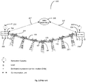
Figure 3 is an exemplary schematic diagram of the distributed intelligent control system for power transfer and line balancing of the HV power grid with local intelligence centers (LINCs) for intercommunication and control of high-speed communication capability enabled self-aware distributed impedance injection modules (CDIIMs). -
Figure 4 is a block representation of the distributed actuator module or the self-aware distributed impedance injection modules (CDIIMs) 102 used with intelligent local control capability and high-speed communication capability as per the invention. -
Figure 5 is a block representation of the other actuator devices that are FACTS control devices, or electronic devices enabled to be coupled to the HV power grid with FACTS-based high-speed control capability and high-speed communication capability for monitoring and control of the HV power grid. -
Figure 6 is a block diagram representation of distributed power generation coupled to the HV power grid with FACTS-based control capability and high-speed communication capability. -
Figure 7 is a block diagram representation of distributed loads with demand response (DR) unit coupled to the HV power grid using FACTS-based control capability and high-speed communication capability. -
Figure 8 is a block representation of the energy storage devices enabled to be coupled, typically within or at the edge of the power grid with FACTS-based control capability and high-speed communication capability. -
Figure 9 is an exemplary block diagram of the total power system from generation to distribution with distributed local sub-cyclic response capability and hierarchical monitoring and supervision capabilities as per an embodiment of the current invention. - The following terms and acronyms are defined specifically to enhance the clarity of the current disclosure only.
- 1. High voltage (HV) power grid - is the HV power transmission system that transports power at high voltage from the power generators to the sub-stations or other distributed loads.
- 2. Total power system - This term includes therein power-generation capability, HV power grid, substations, power distribution capability, any and all power stabilization and control capability associated with the power generation, HV power grid and power distribution, including any energy-storage capabilities.
- 3. DIIMs - Self-aware (with built-in capability to recognize problems / intelligence) Distributed Impedance Injection Modules that are attached to the HV power grid to control the power flow on the HV transmission lines.
- 4. Distributed impedance injection modules- In this disclosure the term refers to high-speed communication capability enabled DIIMs. May also be referred to in the specification as CDIIMs, or individually as an injection module.
- 5. CDIIMs- alternate name for distributed impedance injection modules that are high-speed communication capability enabled DIIMs.
- 6. LINCs - the acronym in this disclosure refers to local intelligence centers connected to a plurality of local CDIIMs for enabling high-speed communication and coordinated local supervisory control.
- 7. High-speed communication capability - in this disclosure refers to communication speeds that enable the system components such as LINCs and self-aware distributed impedance injection modules (CDIIMs) to communicate with each other to respond to local problems at sub-cyclic speeds. (See for example
Fig. 6 in parent Application No.15/068,397, entitled "System and Method for Distributed Grid Control with Sub-Cyclic Local Response Capability" filed on March 11, 2016 - 8. Other actuator devices - In this disclosure other actuator modules refer to the flexible AC transmission systems (FACTS) devices connected to the HV power grid enabled with high-speed (sub-cyclic) communication capability and FACTS-based control capability - also referred to as FACTS control devices. Includes any and all of: static synchronous series compensators (SSSC), static synchronous compensators (STATCOMs), unified power-flow controllers (UPFCs), interline power-flow controllers (IPFCs) and other electronic systems for monitoring and control of the power flow over the HV power grid.
- 9. FACTS control devices - Alternate name for other actuator devices.
- 10. Distributed generators- in this application this refers to the distributed generation capability (other than the large conventional generation stations) that could be inside, at, or outside the edge of the HV power grid but are coupled to the HV power grid with FACTS-based control capability and enabled with high speed communication capability. These include: wind energy farms, Solar energy farms, bioenergy units, wave energy units, etc. that are typically non-conventional producers of energy. This also includes all conventional distributed generation sources but not traditional large generation capabilities such as pre-existing thermal power plants, atomic power plants, hydroelectric plants etc. that are controlled directly by the Supervisory Utility.
- 11. Energy storage devices - in this application distributed energy storage capability typically inside, at, or outside, the edge of the HV power grid but coupled to the HV power grid with or without FACTS-based control and enabled with high speed communication.
- 12. Distributed load demand response - in this application distributed load demand response units mean power distribution systems that are inside, at, or outside the edge of the HV power grid but are coupled to the HV power grid with or without FACTS-based control and enabled with high speed communication.
- 13. Miscellaneous FACTS-coupled actuator devices- refer to the group of systems and subsystems typically inside, at, or outside the edge of the HV power grid, that are described above, but are coupled to the HV power grid with FACTS-based control capability and high speed communication capability. These include distributed generators, distributed energy storage devices, and distributed load demand response (DR) devices.
- 14. Actuator devices - as used in this disclosure refers to all the group of electronic control devices within the edge, at the edge or outside the edge of the HV power grid that are enabled with FACTS-based control capability and high-speed communication capability and are coupled or connected to the HV power grid. The group comprise all or any of the other actuator devices and the miscellaneous FACTS-coupled actuator devices.
- 15. Edge of HV power grid - as used in the current disclosure is a term describing the boundary of the HV power grid, with some temporal and/or spatial functionality outside the direct control of utilities and distribution operators.
- 16. Supervisory utility or utility - In this disclosure supervisory utility refers to the supervisory entity enabled for central monitoring, modelling and control of the total power system having communication links to the LINCs for data collection and providing system control.
- The invention disclosed is generally directed at integrating and using the capabilities of the distributed impedance injection modules, the other actuator modules and the miscellaneous FACTS-coupled actuator devices for providing very high reliability, standardized active control capability that is FACTS-based, to the total power system. The total power system is typically comprised of conventional and distributed generation units, HV power transmission grid, power/ energy storage units, FACTS and non-FACTS control devices inside, at, or outside, the edge of the HV power grid and distributed load demand response units coupling the power distribution systems to the HV power grid. The integrated and hierarchical control capability proposed by the present invention disclosure using distributed impedance injection modules, other actuator modules and miscellaneous FACTS-coupled actuator devices, is a general concept and can be applied with any distributed impedance injection modules, other actuator devices and the miscellaneous FACTS controlled actuator devices inter-linked in a hierarchical fashion using LINCs for transfer of data using the appropriate speed communication capability. The control hierarchy using the CDIIMs, LINCs and Supervisory utility for providing total power system control. These generic concepts are now disclosed using specific implementation details for clarity.
- The details of the invention disclosed are directed at using distributed impedance injection modules such as CDIIMs with local high-speed (speeds that enable sub-cyclic response) communication and control capabilities provided by the local intelligence centers (LINCs), in high-speed communication with other actuator devices and miscellaneous FACTS-coupled actuator devices at and outside the HV power transmission grid edge. Such an integrated local communication and control is able to provide very high reliability, integrated and hierarchically managed, and standardized active control capability to the total power system. The total power system, as described previously, is comprised of distributed generation units, HV power transmission grid, energy storage units, other actuator devices and power distribution systems. The integrated control capability disclosed by the present invention using distributed impedance injection modules, other actuator devices and miscellaneous FACTS-coupled actuator devices are general concepts that are not meant to be limiting or be applicable using only a specific set of distributed impedance injection modules and other actuator devices. The invention can be implemented fully or partially using any appropriate distributed impedance injection modules, other actuator devices and miscellaneous FACTS-coupled actuator devices, that are within, at the edge, and outside the edge of the HV power grid as long as these have the capability for providing control and stability to the total power system including generation, transmission and distribution systems. In effect such proposed integrated control capability can be used effectively for transmission systems and distribution systems that include all micro-grid concepts and implementations.
Fig. 3 shows the distributed and hierarchical intelligent control system for the HV power grid. Sub-cyclic control has been identified as an essential need to have a stable and dynamic HV power grid and total power system. The HV power grid and the total power system should be able to handle issues of stability, intermittency, and transients that are inherent in the new distributed or localized renewable power generation and distributed loads that are being coupled to the HV power grid. For the HV power grid and the total power system to be stable under these conditions, it is necessary for the response to disturbances on the grid to be within milliseconds (sub-cyclic) to prevent them from growing into major power delivery and quality issues, even brownouts. - Centralized control of the grid using high-level algorithms and modeling used for HV power grid control, in the past and currently, is not efficient in achieving the needed response under the above-described conditions due to the time delays inherently associated with the detection, communication, centralized decision making with associated latencies, and action. The solution to this problem is the distributed control based on the local distributed control modules, such as the intelligent and self-aware distributed impedance (or equivalent voltage) injection modules attached to the
HV transmission lines 108 suspended from thetowers 201, such as theCDIIMs 301 coupled to the high voltage (HV)power lines 108. TheseCDIIM 301 or distributed impedance injection modules are made self-aware and have sufficient intelligence, computing capability, communication capability and control capability to respond locally to any sensed disturbance in a sub-cyclic timeframe. To further improve the operational efficiencies of the HV power grid and provide fast response capability to overcome any disturbances recognized by theCDIIMs 301 locally,fast communication capability 303 has been established between the neighboringCDIIMs 301 and also theCDIIMs 301 and a local supervisory entity, the localized intelligence centers (LINCs) 302. EachLINC 302 provides communication and coordination of the operation of a plurality ofCDIIM 301 covering a local area and also provides for high-speed communication 303 toother LINCs 302 when coordination and fast response is needed for disturbances that have the possibility of spreading to neighboringLINCs 302 controlled segments of the HV power grid.Communication 305 is also established from theLINCs 302 to and from the utility supervisory 206 using normal communication channels.Such communication 207 is also established to and from thesubstations 204 to theutility supervisory 206. These normal speed communication channels are used for monitoring, and supervisory control of the power grid, and the collection of data on power grid operations for simulation and optimization of the HV power grid operations. InFig. 3 thegenerators 203 and loads 205 are shown connected to thesub-stations 204 which is no longer the case in the distributed generation power system that is currently evolving. - The aim of the disclosed invention is to expand the operation of the distributed impedance injection modules CDIIMs, LINCs to optimize the operation of the total power system by providing standardized high-speed local control capability and high-speed local communication (sub-cyclic speeds) capability to the components and subsystems in the local segments of the HV transmission grid and the total power system. Currently a number of FACTS-based monitoring and control capabilities and FACTS-coupled subsystems that influence the operation of the total power system from generation to distribution are being implemented within, at the edge and outside the edge of the total power system. It is the aim of the current invention to integrate the capabilities of all these subsystems locally with the CDIIMs and LINCs to provide a standardized local control capability. This standardized local control capability is established by inter-connected distributed impedance (or equivalent voltage) injection modules, LINCs, other actuator devices and miscellaneous FACTS-coupled actuator devices. All of these are enabled with high-speed communication capability and FACTS-based control capability to allow these components and subsystems of the total power system to react to disturbances and changes in power inputs and outputs to the total power system in a sub-cyclic manner at the local level. The distributed impedance injection modules CDIIMs are still used to recognize the disturbances and problems of the HV power grid at the local level and, through the connected LINCs, are able to coordinate with the other actuator devices and miscellaneous FACTS-coupled actuator devices locally to provide optimum responses to the disturbances and problems identified. This helps to prevent the buildup of problems in the HV power grid and the associated subsystems, comprising the total power system. The invention uses the built-in high-speed FACTS-based control capability and high-speed communication capability of the CDIIMs, currently used for fast recognition and correction of localized power flow imbalances or other instabilities or alternate conditions to also recognize any disturbances of the local connected sections of the HV power grid. The invention standardizes this type of control capability and communication capability and extends it to the coupled controllable devices that are the other actuator devices and the miscellaneous FACTS-coupled actuator devices, inside, at the edge and outside the edge of the high-voltage power grid to achieve an integrated and coordinated power flow control and disturbance recovery capability for the total power system. To reduce the cost and provide additional flexibility for use with existing DIIMs, a plug-in version of the standardized high-speed communication module is also implemented, that convert the currently used self-aware intelligent distributed impedance (or equivalent voltage)
injectors DIIMs 102 to distributed impedanceinjection modules CDIIMs 301. By providing the added high-speed communication capability to theDIIMs 102, converting them to distributed impedanceinjection modules CDIIMs 301 connected to theLINCs 302, theCDIIMs 301 andLINCs 302 are able to coordinate the actions of these CDIIM and other actuator devices and the miscellaneous FACTS-coupled actuator devices to respond in a coordinated fashion at the local level and also on a total power system level to the needs of the total power system, increasing system stability and security. By using all these interconnected actuators over the total power system, including the CDIIMs, and other actuator devices and connected miscellaneous FACTS-coupled actuator devices such as distributed generation systems, energy storage systems, distributed load demand response (DR) devices with FACTS-based control etc. inside and outside the edge of the HV power grid, a smooth and optimum control for transfer of power from the generation to distribution is achieved. - The changing nature of the new distributed generation sources, mainly from renewable resources, create the problem of uncontrollable power fluctuations on the total power system. Since this is the nature of all renewable energy resources, it is essential that the total power system is able to take care of the power fluctuations caused. That together with reduced inertia and reduced damping of these new generation sources, compared to the traditionally large conventional generation sources, is the reason why a distributed and agile solution that is different is required for control of the total power system. The control capability provided typically by the distributed impedance injection modules in coordination with other actuator devices and miscellaneous FACTS-coupled devices, (including the distributed generation sources and energy storage devices coupled to the HV power grid) that are interlinked through these CDIIMs and LINCs, using the high-speed communication capability, for information transfer and coordinated control, provide the ability to mitigate the impact of the variations and fluctuations on the transmission grid and the total power system. The only way to overcome the variations and fluctuations on the total power system efficiently is to provide for local control of multiple points of the total power system concurrently, using the FACTS-based control and high-speed communication capabilities, built into the components and sub-systems of the total power system as per the present disclosed invention.
- In the disclosed embodiment of the invention the distributed impedance (or equivalent voltage) injection modules that have intelligence and self-awareness built in are able to update the reference settings for itself and other actuator devices and miscellaneous FACTS-coupled devices, locally connected to it through the LINCs. This capability to dynamically adjust these settings as the local power system operating conditions change, especially due to the distributed nature of the renewable energy sources and loads, while the total power system is in operation, has not been attempted or thought of in the past. This is a key distinguishing feature of the current disclosed invention. This feature is applicable to both transmission as well as distribution systems that have the disclosed features.
- Another important feature of the total power system control proposed is the integration of distributed energy storage devices, that are inside or outside the grid edge, into the total power system enabling control in a distributed and hierarchical fashion as a part of the integrated and standardized control of the, systems and subsystems of the total power system as an embodiment of the invention. A cause of instability of the HV power grid, especially under disturbances and fault conditions is the sudden changes in the phase angle during power injection or load changes by the distributed generation and distributed loading. By having the fast response capability to store any additional power and supply any additional load, from distributed locally controlled Energy storage devices, the propensity for instabilities and oscillations of the grid can be reduced or eliminated. This capability is further improved by the local control of the distribution provided by the Distributed Load demand response unit with FACTS-based control as per an embodiment of the invention.
- The main components of the system to achieve the above include:
- 1. The first is to have distributed impedance (or equivalent voltage) injection modules attached to the power lines that are intelligent, self-aware, and can react independently to disturbances on the localized portions of the power grid.
The CDIIM developed by the inventors and assigned to the inventors' parent organization meets the above requirement for distributed power grid control. - 2. The second need is to have the miscellaneous FACTS-coupled actuator devices within the power grid, at the edge of the power grid, and outside the the power grid, such as distributed generators, (wind farm, solar farm etc.), energy storage devices (pumped storage, battery storage, flywheel storage, superconducting storage etc.), and other actuator devices, (such as devices providing Demand Response (DR) capabilities, and combinations of power system components with power electronic components that enable monitoring etc. in generation and distribution) all connected to the to the total power system using FACTS-based control, and enabled with standardized high-speed communication and control capability, such that they are enabled to communicate and interact with the supervising controllers designated localized intelligence centers (LINCs).
- 3. The third need is to establish high-speed interconnect and communication capability between the distributed impedance injection modules or CDIIM, and LINCs and the other connected actuator devices and miscellaneous FACTS-coupled actuator devices that comprise the distributed generators and storage devices, and other FACTS control devices coupled to the HV power grid, at and outside the HV power grid edge, with local supervising controllers, designated LINCs within the HV power grid and at the edge of the HV power grid. This enables coordinated action of the distributed impedance injection modules and all the other connected actuator devices in the total power system, to overcome and /or limit the disturbances within the local control area and the total power system via control capability established in a hierarchical manner. The communication capability enables heirarchical control, which is distributed control of the HV power grid segments by the
CDIIM 301, providing local control of all connected and coupled devices and systems in the local area by theLINCs 302, to the total power system control by utility supervisory 206 in that order. - 4. The established communication capability via reasonably fast and secure communication links interconnecting the local supervisory modules and communicating with the utility central supervisory control form the enabler for data compilation for simulations and for major remedial action in case of problems that cannot be resolved by the distributed impedance injection modules and the interconnected LINCs supervisory at the local level within the total power system.
-
Fig. 4 shows a distributed impedance (or equivalent voltage) injection module (CDIIM 301) comprising a distributed impedance (or equivalent voltage)injection module 102 with anintelligent control capability 402 and high-speed communication capability 410, typically a high-speed transceiver, with connectivity throughhigh speed link 303 to provide the sub-cyclic local response capability. -
Fig. 5 is an exemplary block diagram of a FACTS monitoring andcontrol module 500 that form other actuator devices that provide the capability for the FACTSelectronic devices 501 connected to the total power system for controlling and analyzing its operation using the FACTS-basedcontrol capability 502 with high-speed communication capability 410, enabled throughhigh speed link 303. -
Fig. 6 is a block diagram 600 showing the modification of the distributedgeneration capability 601, such as wind generation facility, solar generation facility, biogas generation facility, or other distributed power generation facility or facilities, coupled to the total power system using FACTS-basedcontrol capability 602. This enable FACTS-basedcontrol 602 of power generation and input into the HV power grid with high-speed communication capability 410 and connected via ahigh spped link 303 for local communication to LINCs at the edge of the power grid for establishing integrated local control capability. This enable power input changes to be locally recognized and corrective action taken locally to prevent unwanted disturbances being introduced. -
Fig. 7 is a block diagram 700 of the distributed loads 205 that include the FACTS-based demand response (DR)control capability 702 and the high-speed communication capability 410 via highspeed communication link 303, enabling load changes to be locally recognized and corrective actions initiated. -
Fig. 8 is a block diagram 800 showing the modifications that enable theenergy storage devices 801 outside the edge of thepower grid 300 coupled to the HV power grid. Acontroller 802, which in the case shown is a FACTS-based controller and a high-speed communication capability 410 with inter connections usinghigh speed links 303 form part of the control capability for the total power system. -
Fig 9 is ablock schematic 900 of the total power system as per the present invention, with twoHV power grids impedance injection modules 301,other actuator devices 500 that are enabled with distributed standardized control and communication capabilities. The current invention uses the capabilities established for sub-cyclic control and appropriate communication for all the distributedimpedance injection modules 301,other actuator devices 500 and the miscellaneous FACTS-coupled devices, such as distributedgenerators 600,energy storage devices 800 etc. that are inside, at the edge and outside the edge of thepower grid 300 to provide a distributed but integrated sub-cyclic control and response capability to thetotal power system 900. These enable optimization of the operation of thetotal power system 900 from generation to distribution. In the disclosed exemplary implementation theCDIIM 301,LINCs 302,other actuator devices 500, theEnergy Storage devices 800, and the distributedgeneration capabilities 600, as well as the distributed loads withDR capabilities 700, are all with control capability that is typically FACTS-based and are interconnected locally using the high-speed communication capability 410 provided by the high-speed communication links 303 associated with each of the devices as shown and described inFig. 4 to Fig. 8 ., This communication capability is provided through thenearest LINC 302, shown inFig. 9 , for localized communication and control supervision. TheLINCs 302 are also interconnected with high-speed link connections 303 for high-speed inter-LINC communication between the neighboring local areas. TheLINCs 302 are further connected to the utility supervisory 206 usingcommunication connections 305 which may be slower than the high-speed connection links 303, to enable data transfer and overall supervisory control of the total power system. - The control and communication capabilities of the
total power system 900, implemented within, at the edge and outside the edge ofpower grid 300 are integrated using typically the FACTS-based control, and high-speed communication at each of the actuator modules, other actuator devices and miscellaneous FACTS-coupled actuator devices, and covers the total power system from generation to distribution. Such a system can provide optimized, dynamic, localized control of power flows from generators to loads by adjusting the generation outputs and line currents of the HV transmission grid based on system constraints and load requirements. The high-speed communication capabilities linking theCDIIM 301,LINCs 302, with the FACTS-coupledgenerators 600, DR-controlledloads 700,other actuator devices 500, and FACTS-coupledenergy storage devices 800 provide a system-level capability for localized, intelligent and capable of sub-cyclic control of all connected subsystems and devices within thetotal power system 900. - A typical example is when a distributed load comes online suddenly. Due to the inertia of the system, it takes time for the main generators to rev up and increase the supply current. The sudden increase in load can cause oscillations and droop in voltage on the HV Power grid and hence at the connected loads. In the disclosed system the drop in voltage at the load and oscillations are sensed by the distributed monitoring and control facility of the
CDIIM 301. Thelocal CDIIM 301 respond to the oscillations by producing and injecting damping voltages on the line as has been described in the parent application. In this instance the monitoring and control capability of theCDIIM 301 linked, using high-speed communication links, directly or throughLINCs 302 toother CDIIMs 301, to distributed local monitoring and control capability of FACTS-coupledgenerators 600, and FACTS-coupledstorage devices 800. The control information / instructions provided from theCDIIMs 301 enable any locally connected FACTS-coupledenergy storage devices 800 to be switched in to provide the necessary load current while the local distributed FACTS-coupled generators or the main conventional generators under supervisory control are reved up and brought online to cater to the load, thus enabling a much faster and smoother response to the additional load than possible with the current generator- distribution systems. The local monitoring and control capability at the distributed generators, load and the energy storage devices working together at the local level can resolve the problem of oscillations and sagging voltage at the distributed load. The information collected of the problem identified and the corrective action is also intimated to thesupervisory utility 206 over thestandard communication link 305. Thesupervisory utility 206 can then decide if any further action to re-balance the HV power grid and the total power system from generators to distribution is warranted for optimum operating efficiency of thetotal power system 900. - A second example will be when a distributed generation capability such as wind or solar generation is brought online suddenly. Due to the low inertia associated with these generating systems they can be turned on and connected to the grid to pump energy into a stable operating HV power grid. This low inertia input can result in oscillations and unbalancing of the HV power grid and the total power system. The local sensing and monitoring capability of the
CDIIM 301 senses the oscillations and the unbalanced HV power grid condition and the control element reacts by generating and injecting the necessary impedance/voltages to dampen the oscillations and to re-balance the HV power grid. At the same time, theCDIIM 301 communicate over the high-speed links to theLINCs 302 to inform and provide control instructions to the FACTS control at the distributed FACTS-coupledgenerators 600 to control the rate of injection of power onto the HV power grid. TheLINCs 302 also instruct the FACTS controllers at the FACTS-coupledenergy storage devices 800 to enable storing of the excess energy pumped into the HV power grid till the HV power grid is brought back to equilibrium. Hence by using the local monitoring, control and communication capabilities at the distributedimpedance injection modules 301LINCs 302, the FACTS-coupled distributedgenerators 600 and the FACTS-coupledenergy storage devices 800, all with high-speed communication capability, the HV power grid and the total power system stability is maintained even under these adverse conditions. The identified cause of HV power grid disturbance and the solution are also intimated to thesupervisory utility 206 over thecommunication link 305 by theLINCs 302. Thesupervisory utility 206 can then decide if all the components of the total power system from generators to transmission to distribution need to be optimally re-balanced. - The disclosed
total power system 900 is hence able to respond optimally and locally at high-speed, (at sub-cyclic speed) to any of the disturbances on thetotal power system 900. Thetotal power system 900 is also able to optimize its operations from the generation of power, transmission of power over high voltage transmission lines of the HV power grid, to the distribution of power needed at the appropriate voltage levels and phases. The disclosed invention provides also for monitoring and control of the general operation of the HV power grid and thetotal power system 900, for operations such as, but not limited to, line balancing, harmonic reduction or elimination, and monitoring and control of all other important system characteristics. The monitoring and control of thetotal power system 900 uses the hierarchical control capability established by the currently disclosed invention. All of the above are collectively referred to as "conditions"-conditions on the total power system including the high voltage transmission lines of the HV power grid in the claims to follow.
Claims (15)
- A high voltage power grid comprising:high voltage transmission lines (108) configured to transport power at high voltage from power generators (203) to substations (204) or other distributed loads (205);a plurality of high-speed communication enabled distributed impedance injection modules (CDIIMs; 301) distributed along a plurality of segments of the high voltage transmission lines (108), each high-speed communication enabled distributed impedance injection module (CDIIM; 301) being attached to a segment of the high voltage transmission lines (108) and comprising an impedance injection module (IIM;102) configured to inject an impedance or equivalent voltage on the segment of the high voltage transmission line (108), and configured to have a transmission line current measuring capability, a computing capability, a control capability (402) and a high-speed communication capability (410); the high-speed communication enabled distributed injection modules (CDIIMs; 301) are configured to respond locally to any sensed disturbance in a sub-cyclic timeframe and are configured to sense an unwanted change in the transmission line current on the high voltage transmission lines (108) to which it is attached and configured to inject an impedance to compensate for the unwanted change;a plurality of local intelligence centers (LINCs; 302), each local intelligence centers (LINCs; 302) having a high-speed communication capability configured to provide communication and local supervisory coordination of the operation of a plurality of high-speed communication enabled distributed impedance injection modules (CDIIMs; 301) covering a respective local area comprising a subplurality of segments of the high voltage transmission line (108), each high-speed communication enabled distributed impedance injection module (CDIIMs; 301) being in communication with at least one local intelligence center (LINC; 302);each of the local intelligence centers (LINCs; 302) is configured to be further linked with neighboring local intelligence centers (LINCs; 302) through the high-speed communication capability to provide an integrated control capability across neighboring local areas, when coordination and fast response is needed for large disturbances that have the possibility of spreading to segments of the high voltage transmission line (108) controlled by the neighboring local intelligence centers (LINCs; 302);wherein the high-speed communication capability between the local intelligence centers (LINCs; 302), and between the local intelligence centers (LINCs; 302) and the high-speed communication enabled distributed impedance injection modules (CDIIMs; 301) is a communication with sub-cyclic speed and is configured to allow a response to disturbances on the grid to be sub-cyclic;a utility supervisory (206) configured to have a communication capability (305) with the power generators (203), the substations (204) and the local intelligence centers (LINCs; 302);whereby a hierarchical control capability is established wherein:the high-speed communication enabled distributed impedance injection modules (CDIIMs; 301) are configured to respond themselves locally to tend to reduce local disturbances,one or more local intelligence centers (LINCs; 302) are configured to coordinate a response of the plurality of high-speed communication enabled distributed impedance injection modules (CDIIMs; 301) as needed to respond to large disturbances, and the utility supervisory (206) is configured to balance and control the power grid through control of the substations (204), local intelligence centers (LIN Cs; 302) and power generators (203).
- The high voltage power grid of claim 1 further comprising distributed generation units (600), each having a FACTS based control (602) configured to have a high-speed communication capability (410), each distributed generation unit (600) being in high-speed communication (303) with at least one local intelligence center (LINC; 302) configured to control the respective distributed generation unit (600).
- The high voltage power grid of claim 2 wherein the distributed generation units (600) comprise at least one of wind powered generation units, solar powered generation units, bioenergy power generation units or wave powered generation units.
- The high voltage power grid of claim 1 further comprising distributed energy storage devices (800), each having a FACTS based control (802) configured to have a high-speed communication capability (410), each distributed energy storage device (800) being in high-speed communication (303) with at least one local intelligence center (LINC; 302) configured to control the distributed energy storage devices (800).
- The high voltage power grid of claim 4 wherein the distributed energy storage devices (800) comprise at least one of pumped storage, battery storage, flywheel storage or superconducting storage.
- The high voltage power grid of claim 1 further comprising at least one electronic system (500) configured to monitor and control a power flow over the high voltage power grid having a FACTS based control (502) configured to have a high-speed communication capability (410), each electronic system (500) being configured to monitor and control the power flow over the high voltage power grid being in high-speed communication (303) with at least one local intelligence center (LINC; 302) configured to communicate with and control of the electronic system (500) configured to monitor and control of the power flow over the high voltage power grid.
- The high voltage power grid of claim 6 wherein the at least one electronic system (500) configured to monitor and control the power flow over the high voltage power grid comprises at least one of a static synchronous series compensator, a static synchronous compensator, a unified power-flow controller or an interline power-flow controller.
- The high voltage power grid of claim 7 wherein the at least one of a static synchronous series compensator, a static synchronous compensator, a unified power-flow controller or an interline power-flow controller is a FACTS based compensator or controller.
- The high voltage power grid of claim 1, wherein the high-speed communication enabled distributed impedance injection modules (CDIIMs; 301) are configured to modify and update a reference settings for itself and for other actuator devices and miscellaneous FACTS-coupled actuator devices (500, 600, 700, 800), locally connected to it through the local intelligence centers (LINCs; 302), based on changes to the high voltage power grid operating conditions, while the high voltage power grid is in operation.
- A method of controlling a high voltage power grid having high voltage transmission lines (108) configured to transport power at high voltage from power generators (203) to sub-stations or other distributed loads (205) comprising:coupling a plurality of high-speed communication enabled distributed impedance injection modules (CDIIMs; 301) to the high voltage transmission lines (108), the plurality of high-speed communication enabled distributed impedance injection modules (CDIIMs; 301) distributed along a plurality of segments of the high voltage transmission lines (108), each high-speed communication enabled distributed impedance injection module (CDIIM; 301) being attached to a segment of the high voltage transmission lines (108) and comprising an impedance injection module (IIM; 102) configured to inject impedance or equivalent voltages into the respective high voltage transmission line (108), each high-speed communication enabled distributed impedance injection module (CDIIM; 301) configured to have a transmission line current measuring capability, an intelligent control capability, a computing capability and a high-speed communication capability; the high-speed communication enabled distributed impedance injection modules (CDIIMs; 301) configured to respond locally to any sensed disturbance in a sub-cyclic timeframe and being configured to sense an unwanted change in the transmission line current on the high voltage transmission line to which it is attached and configured to inject an impedance to compensate for the unwanted change;providing a plurality of local intelligence centers (LINCs; 302), each having a high-speed communication capability, each local intelligence center (LINC; 302) being in high speed communication with a subplurality of high-speed communication enabled distributed impedance injection modules (CDIIMs; 301) configured for providing local supervisory coordination of the operation of the plurality of high-speed communication enabled distributed impedance injection modules (CDIIMs; 301) covering a local area;transmitting from and receiving current measurements from at least one of the respective high-speed communication enabled distributed impedance injection modules (CDIIMs; 301) at a local intelligence center (LINC; 302) indicative of an unwanted disturbance on the respective high voltage transmission line (108);when the disturbance is larger than can be corrected by one local intelligence center (LINC; 302), transmitting from the respective local intelligence center (LINC; 302) to at least one additional neighboring local intelligence center (LINC; 302) to cause those local intelligence centers (LINC; 302) to transmit instructions to respective high-speed communication enabled distributed impedance injection modules (CDIIMs; 302) to cause those high-speed communication enabled distributed impedance injection modules (CDIIMs; 302) to also inject impedance or equivalent voltages onto the respective high voltage transmission line tending correct the disturbance;wherein the high-speed communication capability between the local intelligence centers (LINCs; 301), and between the local intelligence centers (LINCs; 301) and the high-speed communication enabled distributed impedance injection modules (CDIIMs; 302) is a communication with sub-cyclic speed and allows a response to disturbances on the grid to be sub-cyclic.
- The method of claim 10 wherein the high voltage power grid further comprises a utility supervisory (206) having a communication capability with the power generators (203), substations (204) and the local intelligence centers (LINC; 302), and wherein the utility supervisory (206) balances and controls the power grid through control of the substations (204), local intelligence centers (LINC; 302) and power generators (203).
- The method of claim 11 wherein the high voltage power grid further comprises distributed generation units (600), each having a FACTS based control configured to have a high-speed communication capability, and wherein each distributed generation unit (800) is in high-speed communication with at least one local intelligence center (LINC; 302) configured to control the distributed generation units (600).
- The method of claim 12 wherein the high voltage power grid further comprises distributed energy storage devices (800), each having a FACTS based control configured to have a high-speed communication capability, each distributed energy storage device (800) being in high-speed communication with at least one local intelligence center (LINC; 302) configured to control the distributed energy storage devices (800).
- The method of claim 12 wherein the high voltage power grid further comprises at least one electronic system (500) configured to monitor and control the power flow over the high voltage power grid having a FACTS based control configured to have a high-speed communication capability, each electronic system (500) configured to monitor and control of a power flow over the high voltage power grid being in high-speed communication with at least one local intelligence center (LINC; 302) configured to communicate with and control of the electronic system (500) for monitoring and control of the power flow over the high voltage power grid.
- The method of claim 14 wherein the at least one electronic system (500) configured to monitor and control the power flow over the high voltage power grid comprises at least one of a static synchronous series compensator, a static synchronous compensator, a unified power-flow controller or an interline power-flow controller.
Applications Claiming Priority (5)
| Application Number | Priority Date | Filing Date | Title |
|---|---|---|---|
| US201662294230P | 2016-02-11 | 2016-02-11 | |
| US15/068,397 US10097037B2 (en) | 2016-02-11 | 2016-03-11 | System and method for distributed grid control with sub-cyclic local response capability |
| US201662353479P | 2016-06-22 | 2016-06-22 | |
| US15/428,906 US10218175B2 (en) | 2016-02-11 | 2017-02-09 | Dynamic and integrated control of total power system using distributed impedance injection modules and actuator devices within and at the edge of the power grid |
| PCT/US2017/017559 WO2017139704A1 (en) | 2016-02-11 | 2017-02-10 | Control of power system using distributed impedance injection modules and actuator devices within the power grid |
Publications (3)
| Publication Number | Publication Date |
|---|---|
| EP3414811A1 EP3414811A1 (en) | 2018-12-19 |
| EP3414811A4 EP3414811A4 (en) | 2019-08-28 |
| EP3414811B1 true EP3414811B1 (en) | 2022-05-18 |
Family
ID=59561767
Family Applications (1)
| Application Number | Title | Priority Date | Filing Date |
|---|---|---|---|
| EP17750918.9A Active EP3414811B1 (en) | 2016-02-11 | 2017-02-10 | Control of power system using distributed impedance injection modules and actuator devices within the power grid |
Country Status (5)
| Country | Link |
|---|---|
| US (3) | US10218175B2 (en) |
| EP (1) | EP3414811B1 (en) |
| CN (1) | CN109075577B (en) |
| AU (1) | AU2017218117B2 (en) |
| WO (1) | WO2017139704A1 (en) |
Families Citing this family (22)
| Publication number | Priority date | Publication date | Assignee | Title |
|---|---|---|---|---|
| EP2868919A1 (en) * | 2013-11-05 | 2015-05-06 | Openhydro IP Limited | Turbulence protection system and method for turbine generators |
| US10218175B2 (en) | 2016-02-11 | 2019-02-26 | Smart Wires Inc. | Dynamic and integrated control of total power system using distributed impedance injection modules and actuator devices within and at the edge of the power grid |
| US10666038B2 (en) | 2017-06-30 | 2020-05-26 | Smart Wires Inc. | Modular FACTS devices with external fault current protection |
| US10756542B2 (en) * | 2018-01-26 | 2020-08-25 | Smart Wires Inc. | Agile deployment of optimized power flow control system on the grid |
| US10396533B1 (en) | 2018-02-22 | 2019-08-27 | Smart Wires Inc. | Containerized power flow control systems |
| WO2019242657A1 (en) * | 2018-06-19 | 2019-12-26 | 清华大学 | Micro-grid reconstruction method and apparatus, micro-grid protection control center, and storage medium |
| US11121551B2 (en) * | 2018-08-23 | 2021-09-14 | Smart Wires Inc. | Modular time synchronized injection modules |
| CN109768618A (en) * | 2018-09-03 | 2019-05-17 | 杭州中恒电气股份有限公司 | The auxiliary ac power supply system of monitoring and control based on CAN network communication mode |
| CN109240110A (en) * | 2018-10-09 | 2019-01-18 | 芜湖市越泽机器人科技有限公司 | Intelligent home theater system |
| TWI692181B (en) | 2018-10-16 | 2020-04-21 | 財團法人工業技術研究院 | Electric power regulating system and method thereof |
| US11159046B1 (en) * | 2018-12-21 | 2021-10-26 | Smart Wires Inc. | Dynamic computation and control of distributed assets at the edge of a power grid |
| US11539211B2 (en) * | 2019-06-11 | 2022-12-27 | Smart Wires Inc. | Fast-slow injection for recovery from transient response and voltage collapse with avoidance of SSR and SSCI |
| AU2019204500B2 (en) * | 2019-06-26 | 2025-07-31 | Smart Wires Inc. | Agile deployment of optimized power flow control system on the grid |
| US11411404B2 (en) * | 2019-11-22 | 2022-08-09 | Smart Wires Inc. | Use of the unused duration injection units in an array to reduce oscillations during impedance injection for corrections of problems |
| US11990733B2 (en) * | 2019-12-23 | 2024-05-21 | Terna S.P.A. | Compact electric switching substation into a lattice tower for connection of active and passive users to a high-voltage electric grid and use of said substation for connecting an electric vehicle charging station to a high-voltage electric grid |
| CA3174426A1 (en) | 2020-04-02 | 2021-10-07 | Abhineet H. PARCHURE | Electrical grid control systems and methods using dynamically mapped effective impedance |
| US11735922B2 (en) | 2020-08-28 | 2023-08-22 | Smart Wires Inc. | Temporal balancing of electrical stress on FACTS devices in FACTS based distributed impedance injection units |
| EP4145660A1 (en) * | 2021-09-01 | 2023-03-08 | Smart Wires Inc. | Dynamic computation and control of distributed assets at the edge of a power grid |
| US12609530B2 (en) * | 2021-11-30 | 2026-04-21 | Smart Wires Inc. | Dynamic computation and heirarchical control of assets of a power grid using shunt and series connected FACTS devices |
| CN115632480A (en) * | 2022-10-27 | 2023-01-20 | 上海兴夏信息科技有限公司 | A new energy grid-connected communication network planning and optimization method and system |
| TWI866510B (en) * | 2023-10-02 | 2024-12-11 | 強弦科技股份有限公司 | Circuit architecture for bidirectional power flow with ai control |
| TWI912168B (en) * | 2025-03-18 | 2026-01-11 | 國立高雄科技大學 | Offshore wind farm grid-connected random harmonic impact analysis method |
Family Cites Families (143)
| Publication number | Priority date | Publication date | Assignee | Title |
|---|---|---|---|---|
| US2237812A (en) | 1940-02-23 | 1941-04-08 | Gen Electric | Portable unit substation |
| GB540706A (en) * | 1940-09-05 | 1941-10-27 | Edison Hallowell | Improvements in or relating to the generation and transmission of high frequency currents |
| US2551841A (en) | 1946-11-27 | 1951-05-08 | Westinghouse Electric Corp | Electrical apparatus |
| US3556310A (en) | 1968-05-27 | 1971-01-19 | Jack Loukotsky | Prefabricated modular power substation |
| US3704001A (en) | 1970-11-17 | 1972-11-28 | Clifford E Sloop | Mounting bracket |
| US3750992A (en) | 1972-06-26 | 1973-08-07 | E Johnson | Transformer mounting assembly |
| DE2354663C3 (en) | 1973-10-31 | 1976-07-15 | Siemens Ag | CONVERTER |
| US4057736A (en) | 1974-09-13 | 1977-11-08 | Jeppson Morris R | Electrical power generation and distribution system |
| US4025824A (en) | 1976-02-12 | 1977-05-24 | Cheatham Harry P | Transformer support rack |
| US4200899A (en) | 1976-07-16 | 1980-04-29 | Grinshtein Vladimir Y | Outdoor high-voltage switchgear |
| US4103853A (en) | 1976-12-22 | 1978-08-01 | Mcgraw-Edison Company | Aluminum cluster mount |
| US4164345A (en) | 1978-02-03 | 1979-08-14 | Arnold William L | Safety cradle for transformer repair |
| NL175362C (en) | 1978-10-27 | 1984-10-16 | Hazemeijer Bv | MAIN DISTRIBUTION STATION AND SUB-DISTRIBUTION STATION FOR ELECTRIC ENERGY DISTRIBUTION. |
| JPS5936091Y2 (en) | 1978-11-24 | 1984-10-05 | 株式会社明電舎 | Mobile substation equipment |
| SE421036B (en) | 1979-03-27 | 1981-11-16 | Asea Ab | HOGS MONETARY DEVICE |
| US4286207A (en) | 1980-04-14 | 1981-08-25 | Westinghouse Electric Corp. | High-power AC voltage stabilizer |
| US4323722A (en) | 1980-09-24 | 1982-04-06 | The United States Of America As Represented By The United States Department Of Energy | Overhead electric power transmission line jumpering system for bundles of five or more subconductors |
| JPS5857216U (en) | 1981-10-13 | 1983-04-18 | 三菱電機株式会社 | mobile substation |
| US4514950A (en) | 1981-11-27 | 1985-05-07 | Goodson Jr Albert A | Building framing system and method |
| SE437314B (en) | 1983-07-11 | 1985-02-18 | Asea Ab | DEVICE FOR THE COLLECTION OF ELECTRIC HIGH VOLTAGE EQUIPMENT |
| US5032738A (en) | 1986-01-22 | 1991-07-16 | Vithayathil John J | Scheme for rapid adjustment of network impedance |
| US4710850A (en) | 1986-02-19 | 1987-12-01 | Siemens Aktiengesellschaft | Tower design for high-voltage systems |
| JPH0727788Y2 (en) | 1986-05-23 | 1995-06-21 | 住友電気工業株式会社 | Monitoring equipment for overhead power transmission and distribution equipment |
| US5006846A (en) | 1987-11-12 | 1991-04-09 | Granville J Michael | Power transmission line monitoring system |
| US4903927A (en) | 1988-09-29 | 1990-02-27 | Aluma-Form, Inc. | Electrical equipment cluster mount |
| US5023768A (en) | 1989-11-24 | 1991-06-11 | Varian Associates, Inc. | High voltage high power DC power supply |
| US5193774A (en) | 1992-05-26 | 1993-03-16 | Rogers J W | Mounting bracket apparatus |
| US5461300A (en) | 1993-03-30 | 1995-10-24 | Electric Power Research Institute, Inc. | Phase angle regulating transformer with a single core per phase |
| US5513061A (en) | 1993-12-09 | 1996-04-30 | Long Island Lighting Company | Apparatus and method for distributing electrical power |
| EP0669686B1 (en) | 1994-02-26 | 1997-11-19 | Asea Brown Boveri Ag | Suspension assembly for an apparatus |
| US5469044A (en) | 1995-01-05 | 1995-11-21 | Westinghouse Electric Corporation | Transmission line power flow controller with unequal advancement and retardation of transmission angle |
| US5610501A (en) | 1995-02-01 | 1997-03-11 | Westinghouse Electric Corporation | Dynamic power and voltage regulator for an ac transmission line |
| JP2910616B2 (en) | 1995-04-27 | 1999-06-23 | 三菱電機株式会社 | Voltage source type power converter |
| US5648888A (en) | 1995-12-27 | 1997-07-15 | Hydro-Quebec | Power distribution substation |
| US5844462A (en) | 1996-04-29 | 1998-12-01 | Alliedsignal Inc. | Magnetic core-coil assembly for spark ignition systems |
| US6088249A (en) | 1997-12-02 | 2000-07-11 | Power Circuit Innovations, Inc. | Frequency modulated ballast with loosely coupled transformer |
| US6134105A (en) | 1998-01-06 | 2000-10-17 | Lueker; Mark David | Portable command center |
| US5986617A (en) | 1998-08-31 | 1999-11-16 | Lucent Technologies | Multiband antenna matching unit |
| US6486569B2 (en) | 1998-12-04 | 2002-11-26 | Hydro-Quebec | Power flow management in an electric power grid |
| CA2253762A1 (en) | 1998-12-04 | 2000-06-04 | Hydro-Quebec | Apparatus and switching method for electric power transmission lines |
| US6912487B1 (en) | 1999-04-09 | 2005-06-28 | Public Service Company Of New Mexico | Utility station automated design system and method |
| US6215653B1 (en) | 1999-07-15 | 2001-04-10 | Aep Resources Services Company | Modular electrical substation and method of constructing same |
| US6147581A (en) | 1999-11-17 | 2000-11-14 | Asea Brown Boveri Inc. | Universal transformer tank for pole-mounted distribution transformers |
| US6831377B2 (en) | 2000-05-03 | 2004-12-14 | University Of Southern California | Repetitive power pulse generator with fast rising pulse |
| US6233137B1 (en) | 2000-05-25 | 2001-05-15 | Mathias Kolos | Compact power distribution substation |
| US6335613B1 (en) | 2000-12-04 | 2002-01-01 | Abb T&D Technology Ltd. | Versatile power flow transformers for compensating power flow in a transmission line |
| JP4340001B2 (en) | 2000-12-26 | 2009-10-07 | 日立電線株式会社 | Branching method for overhead transmission lines |
| DE10157590A1 (en) | 2001-11-23 | 2003-06-05 | Abb T & D Tech Ltd | Winding for a transformer or a coil |
| EP1443624A1 (en) | 2003-01-31 | 2004-08-04 | Viserge Limited | Fault control and restoration in a multi-feed power network |
| FR2851636B1 (en) | 2003-02-21 | 2005-06-03 | Alstom | SIDE-LOADED ARTICULATING SUPPORT FOR HIGH OR MEDIUM VOLTAGE ELECTRICAL EQUIPMENT |
| CA2427333C (en) | 2003-04-30 | 2008-12-16 | Va Tech Transformateurs Ferranti-Packard (Quebec) Inc. | Distribution transformer |
| JP2005045888A (en) | 2003-07-25 | 2005-02-17 | Toshiba Corp | Power distribution tower |
| US7193338B2 (en) | 2003-09-05 | 2007-03-20 | Ghali Gamal A | Method for tapping a high voltage transmission line and substation using the same |
| US7105952B2 (en) | 2003-10-03 | 2006-09-12 | Soft Switching Technologies Corporation | Distributed floating series active impendances for power transmission systems |
| US7091703B2 (en) * | 2004-03-04 | 2006-08-15 | American Superconductor Corporation | Dynamic reactive compensation system and method |
| US7352564B2 (en) | 2004-10-16 | 2008-04-01 | Eaton Corporation | Power distribution substation |
| KR20120053057A (en) | 2005-01-31 | 2012-05-24 | 조지아 테크 리서치 코오포레이션 | Active current surge limiters |
| EP1737098A1 (en) | 2005-06-24 | 2006-12-27 | Abb Research Ltd. | Damping electromagnetic oscillations in power system |
| CN1737588A (en) * | 2005-09-09 | 2006-02-22 | 武汉大学 | A live measurement method and device for zero-sequence parameters of a mutual inductance line |
| EP1938159B1 (en) | 2005-09-16 | 2016-08-24 | Ampacimon S.A. | Device, system and method for real-time monitoring of overhead power lines |
| US7460931B2 (en) | 2005-10-07 | 2008-12-02 | Jay Jacobson | Method and system for improving the efficiency and reliability of a power grid |
| WO2007065135A2 (en) * | 2005-11-30 | 2007-06-07 | Alternative Energy Systems Consulting, Inc. | Agent based auction system and method for allocating distributed energy resources |
| KR100776352B1 (en) | 2006-04-25 | 2007-11-15 | 한국전력공사 | Automatic operation system of the PCC in conjunction with SCAD and its method |
| JP4830705B2 (en) | 2006-08-04 | 2011-12-07 | 三菱電機株式会社 | Reactive power control device and reactive power compensation device |
| KR100827571B1 (en) | 2006-10-31 | 2008-05-07 | 한국전력공사 | SCAD Online FAC Simulator System |
| US7547843B2 (en) | 2006-12-28 | 2009-06-16 | 3M Innovative Properties Company | Overhead electrical power transmission line |
| JP5108031B2 (en) | 2007-02-20 | 2012-12-26 | エービービー・リミテッド | Magnetic flux control system for active voltage regulation |
| US7920392B2 (en) | 2007-05-11 | 2011-04-05 | Soft Switching Technologies Corporation | Dynamic voltage sag correction |
| US8996183B2 (en) | 2007-08-28 | 2015-03-31 | Consert Inc. | System and method for estimating and providing dispatchable operating reserve energy capacity through use of active load management |
| WO2009034517A2 (en) | 2007-09-10 | 2009-03-19 | St-Nxp Wireless (Holding) Ag | Electronic device, barrel shifter unit and method of barrel shifting |
| DE102007047165A1 (en) | 2007-09-26 | 2009-04-16 | Siemens Ag | power supply |
| US8121741B2 (en) | 2008-05-09 | 2012-02-21 | International Business Machines Corporation | Intelligent monitoring of an electrical utility grid |
| WO2010081162A1 (en) * | 2009-01-12 | 2010-07-15 | Grid Logic | Method and devices for stabilizing electric grid power |
| US8474780B2 (en) | 2009-04-06 | 2013-07-02 | Pelco Products, Inc. | Cable retainer for utility pole base |
| BRPI1013764A2 (en) | 2009-05-07 | 2016-04-05 | Dominion Resources Inc | "voltage conservation using advanced metering infrastructure and substation centralized voltage control" |
| US8681479B2 (en) | 2009-05-29 | 2014-03-25 | Rosendin Electric, Inc. | Various methods and apparatuses for an integrated power distribution platform |
| US7834736B1 (en) | 2009-07-31 | 2010-11-16 | Abb Technology Ag | Dry type pole-mounted transformer |
| DE102009040090A1 (en) | 2009-09-04 | 2011-03-10 | Voltwerk Electronics Gmbh | Island unit for a power grid with a control unit for controlling an energy flow between the power generation unit, the energy storage unit, the load unit and / or the power grid |
| CA2768101A1 (en) | 2009-09-15 | 2011-03-24 | The University Of Western Ontario | Utilization of distributed generator inverters as statcom |
| EP2491630A1 (en) | 2009-10-20 | 2012-08-29 | ABB Technology Ltd | A system having electrical equipments integrated on a structure and a method for isolation of electrical equipments thereof |
| US8401709B2 (en) | 2009-11-03 | 2013-03-19 | Spirae, Inc. | Dynamic distributed power grid control system |
| US7932621B1 (en) | 2010-01-28 | 2011-04-26 | James Patrick Spellman | Method and apparatus for an integrated wind-solar energy system utilizing an existing wind turbine infrastructure |
| DK2548277T3 (en) | 2010-03-15 | 2016-01-11 | Alstom Technology Ltd | Static reactive power compensator with flertrinskonverter |
| US9178456B2 (en) | 2010-04-06 | 2015-11-03 | Ge Energy Power Conversion Technology, Ltd. | Power transmission systems |
| BR112013002050A2 (en) | 2010-07-28 | 2016-06-07 | Ormazabal Y Cia S L U | modular transformation center |
| KR101797796B1 (en) | 2010-07-30 | 2017-11-15 | 제네럴 일렉트릭 테크놀러지 게엠베하 | Hvdc converter comprising fullbridge cells for handling a dc side short circuit |
| US9124100B2 (en) | 2010-08-04 | 2015-09-01 | Panasonic Intellectual Property Management Co., Ltd. | Power supply system, control device of power supply system, operation method of power supply system, and control method of power supply system |
| US9601925B2 (en) | 2010-09-13 | 2017-03-21 | Aker Subsea As | Stable subsea electric power transmission to run subsea high speed motors |
| KR101132759B1 (en) * | 2010-09-30 | 2012-04-06 | 한국전력공사 | System and method for controlling power flow |
| US8680720B2 (en) | 2010-10-27 | 2014-03-25 | Perfect Galaxy International Ltd. | Automatic AC bus voltage regulation for power distribution grids |
| JP6048146B2 (en) | 2010-11-08 | 2016-12-21 | 日本電気株式会社 | Power system control system and method |
| US8922038B2 (en) | 2010-12-08 | 2014-12-30 | Northern Power Systems, Inc. | Wind power unit having an underslung transformer |
| US8441778B1 (en) | 2010-12-22 | 2013-05-14 | Stephen L. Ashmore | Modular substation feeder assembly |
| CN102694381B (en) | 2011-03-25 | 2014-07-23 | 珠海优特电力科技股份有限公司 | Multistage electrical-network self-healing control method |
| US8890373B2 (en) | 2011-04-04 | 2014-11-18 | Eaton Corporation | Power distribution systems using distributed current sensing |
| US8919584B2 (en) | 2011-04-11 | 2014-12-30 | Abb Technology Ag | Electrical equipment mounting frame |
| KR101053514B1 (en) | 2011-05-20 | 2011-08-03 | 티앤제이건설 주식회사 | Jumper wire connection fixing device for overhead transmission line |
| EP2724446A4 (en) | 2011-06-08 | 2014-10-22 | Socpra Sciences Et Génie S E C | METHOD AND SYSTEM FOR MANAGING DISTRIBUTED ELECTRICAL LOADS TO REGULATE COMMUNITY LOADS |
| US8965590B2 (en) * | 2011-06-08 | 2015-02-24 | Alstom Grid Inc. | Intelligent electrical distribution grid control system data |
| CN102313850B (en) | 2011-06-24 | 2014-07-23 | 中国电力科学研究院 | Physical real-time dynamic simulation device for flexible direct current transmission system |
| JP2013013178A (en) | 2011-06-28 | 2013-01-17 | Hitachi Ltd | Operation control system, operation control device, and operation control method for electric power system |
| US20130033103A1 (en) | 2011-08-02 | 2013-02-07 | Mcjunkin Samuel T | Systems and Methods For Distributed Impedance Compensation In Subsea Power Distribution |
| KR101553945B1 (en) | 2011-08-16 | 2015-09-17 | 엘에스산전 주식회사 | Solid insulated switchgear |
| US8497592B1 (en) | 2011-08-31 | 2013-07-30 | Thomas Jones | Utility pole mountable vertical axis wind turbine |
| US20140246914A1 (en) | 2011-09-12 | 2014-09-04 | Alstom Technology Ltd. | Sub-Synchronous Oscillation Damping By Shunt Facts Apparatus |
| NO334144B1 (en) | 2011-09-12 | 2013-12-16 | Aker Subsea As | Underwater rotating device |
| CN102354981B (en) * | 2011-09-30 | 2013-07-03 | 河海大学 | Distributed computation based voltage stability assessment method of sub-networks in interconnected power network |
| US8957752B2 (en) | 2011-10-07 | 2015-02-17 | Sabic Global Technologies B.V. | Inverter housing system |
| US20140111297A1 (en) | 2012-10-18 | 2014-04-24 | Manufacturing Systems and Equipment Inc. | Wound transformer core and method of manufacture |
| CN102522744B (en) * | 2011-12-01 | 2014-01-22 | 华北电力大学 | A network loss allocation method |
| WO2013126660A2 (en) | 2012-02-24 | 2013-08-29 | Board Of Trustees Of Michigan State University | Transformer-less unified power flow controller |
| US9048649B2 (en) | 2012-03-20 | 2015-06-02 | The Boeing Company | Method and apparatus for anti-icing and deicing power transmission lines |
| US9483063B2 (en) | 2012-04-24 | 2016-11-01 | Elwha Llc | Transmission-line coupled heat-dissipation device with an assembly of one or more controllable fins |
| CN102709917B (en) * | 2012-05-10 | 2015-09-16 | 广东中钰科技股份有限公司 | A kind of dynamic reactive compensation device controlling high pressure based on IGBT |
| US9207698B2 (en) | 2012-06-20 | 2015-12-08 | Causam Energy, Inc. | Method and apparatus for actively managing electric power over an electric power grid |
| US9640997B2 (en) | 2012-07-30 | 2017-05-02 | Siemens Corporation | Power system stabilization using distributed inverters |
| CN104756346B (en) | 2012-08-28 | 2018-04-24 | 智能网股份有限公司 | Power line reactance module and application |
| US9331482B2 (en) | 2012-11-02 | 2016-05-03 | North Carolina State University | Static synchronous compensator systems and related methods |
| CN104797765B (en) | 2012-11-08 | 2017-08-25 | D·卡梅伦 | Modular construction system for solar panel installation |
| WO2014099876A1 (en) | 2012-12-18 | 2014-06-26 | Smart Wire Grid, Inc. | Installation fixture for installing devices on power lines |
| US9762060B2 (en) | 2012-12-31 | 2017-09-12 | Battelle Memorial Institute | Distributed hierarchical control architecture for integrating smart grid assets during normal and disrupted operations |
| US9739070B2 (en) | 2013-01-10 | 2017-08-22 | Kevin M. Bushore | Methods and apparatuses of supporting and bracing a utility pole |
| US8872366B2 (en) | 2013-01-31 | 2014-10-28 | APR Energy, LLC | Scalable portable modular power plant |
| CA2906769C (en) | 2013-03-14 | 2023-03-14 | Innovolt, Inc. | Systems and methods for detecting and determining sources of power disturbances in connection with effective remediation |
| GB2511836A (en) | 2013-03-15 | 2014-09-17 | Control Tech Ltd | Electrical fault detection |
| US9563218B2 (en) | 2013-03-15 | 2017-02-07 | Dominion Resources, Inc. | Electric power system control with measurement of energy demand and energy efficiency using t-distributions |
| US8816527B1 (en) | 2013-03-27 | 2014-08-26 | Smart Wire Grid, Inc. | Phase balancing of power transmission system |
| US20140312859A1 (en) | 2013-03-27 | 2014-10-23 | Smart Wire Grid, Inc. | Phase balancing of power transmission system |
| CN103256337B (en) | 2013-04-24 | 2015-09-02 | 国家电网公司 | Electrical equipment support frame type damping control system and vibration damper selection method, device |
| US9478351B2 (en) | 2013-05-24 | 2016-10-25 | Keithley Instruments, Inc. | Isolation transformer for use in isolated DC-to-DC switching power supply |
| US20140371929A1 (en) * | 2013-06-17 | 2014-12-18 | Schweitzer Engineering Laboratories, Inc. | Source Impedance Estimation |
| US10296988B2 (en) | 2013-08-19 | 2019-05-21 | Board Of Trustees Of Michigan State University | Linear optimal power flow system and method |
| JP6260906B2 (en) | 2013-09-27 | 2018-01-17 | 株式会社アークリエイト | Steel structure pile pillar-to-base beam joint integrated method |
| WO2015074538A1 (en) | 2013-11-21 | 2015-05-28 | 国家电网公司 | Automatic unfolding type on-site calibration vehicle for high-voltage transformers |
| CN203668968U (en) | 2013-12-18 | 2014-06-25 | 中国能源建设集团安徽省电力设计院 | Support supporting component used for transformer substation outdoor AIS electric equipment |
| US9217762B2 (en) | 2014-02-07 | 2015-12-22 | Smart Wires Inc. | Detection of geomagnetically-induced currents with power line-mounted devices |
| CN104113059A (en) * | 2014-06-25 | 2014-10-22 | 国家电网公司 | Node current injection method-based modeling method of unified power flow controller |
| KR101628920B1 (en) | 2014-07-31 | 2016-06-10 | 고려대학교 산학협력단 | Power grid frequency flexibility operation system and method using the same |
| CN105301391B (en) * | 2015-10-20 | 2019-03-29 | 北京动力京工科技有限公司 | Islanding detection device and method based on active filtering and harmonic compensation |
| US10418814B2 (en) | 2015-12-08 | 2019-09-17 | Smart Wires Inc. | Transformers with multi-turn primary windings for dynamic power flow control |
| US10199150B2 (en) | 2015-12-10 | 2019-02-05 | Smart Wires Inc. | Power transmission tower mounted series injection transformer |
| US10218175B2 (en) * | 2016-02-11 | 2019-02-26 | Smart Wires Inc. | Dynamic and integrated control of total power system using distributed impedance injection modules and actuator devices within and at the edge of the power grid |
| US10097037B2 (en) | 2016-02-11 | 2018-10-09 | Smart Wires Inc. | System and method for distributed grid control with sub-cyclic local response capability |
-
2017
- 2017-02-09 US US15/428,906 patent/US10218175B2/en active Active
- 2017-02-10 CN CN201780022768.0A patent/CN109075577B/en active Active
- 2017-02-10 WO PCT/US2017/017559 patent/WO2017139704A1/en not_active Ceased
- 2017-02-10 AU AU2017218117A patent/AU2017218117B2/en active Active
- 2017-02-10 EP EP17750918.9A patent/EP3414811B1/en active Active
-
2019
- 2019-02-21 US US16/282,172 patent/US10749341B2/en active Active
-
2020
- 2020-07-28 US US16/941,196 patent/US11594887B2/en active Active
Also Published As
| Publication number | Publication date |
|---|---|
| US10218175B2 (en) | 2019-02-26 |
| CN109075577B (en) | 2022-05-03 |
| WO2017139704A1 (en) | 2017-08-17 |
| AU2017218117A1 (en) | 2018-08-30 |
| EP3414811A1 (en) | 2018-12-19 |
| EP3414811A4 (en) | 2019-08-28 |
| US20200358288A1 (en) | 2020-11-12 |
| US11594887B2 (en) | 2023-02-28 |
| CN109075577A (en) | 2018-12-21 |
| US20190190264A1 (en) | 2019-06-20 |
| AU2017218117B2 (en) | 2021-05-13 |
| US10749341B2 (en) | 2020-08-18 |
| US20170237255A1 (en) | 2017-08-17 |
Similar Documents
| Publication | Publication Date | Title |
|---|---|---|
| US11594887B2 (en) | Dynamic and integrated control of total power system using distributed impedance injection modules and actuator devices within and at the edge of the power grid | |
| EP3414577B1 (en) | System and method for distributed grid control with sub-cyclic local response capability | |
| Shahgholian | A brief review on microgrids: Operation, applications, modeling, and control | |
| Panda et al. | A review on robust and adaptive control schemes for microgrid | |
| Zhou et al. | Compartmentalization strategy for the optimal economic operation of a hybrid AC/DC microgrid | |
| Ahmed et al. | Review on microgrids design and monitoring approaches for sustainable green energy networks | |
| Unamuno et al. | Hybrid ac/dc microgrids—Part II: Review and classification of control strategies | |
| Meng et al. | Distributed load sharing of an inverter-based microgrid with reduced communication | |
| Minchala-Avila et al. | Optimal energy management for stable operation of an islanded microgrid | |
| Vasquez et al. | Hierarchical control of intelligent microgrids | |
| Zhang et al. | Fully distributed coordination of multiple DFIGs in a microgrid for load sharing | |
| Mehrizi-Sani | Distributed control techniques in microgrids | |
| Shahgholian et al. | Droop control strategy in inverter‐based microgrids: A brief review on analysis and application in islanded mode of operation | |
| Han et al. | Optimization of communication network for distributed control of wind farm equipped with energy storages | |
| Shrivastava et al. | Comprehensive review on hierarchical control of cyber‐physical microgrid system | |
| Wu et al. | Global frequency synchronization of complex power networks via coordinating switching control | |
| Kabalci | Hierarchical control in microgrid | |
| Gao | Study on frequency stability control strategies for microgrid based on hybrid renewable energy | |
| Gaiceanu et al. | DC microgrid control | |
| Arshad et al. | Multi-agent based distributed voltage regulation scheme with grid-tied inverters in active distribution networks | |
| Gupta et al. | Optimized operation of AC–DC microgrid cluster with modified PLL and socket protocol | |
| Mahmud et al. | Control of renewable energy systems | |
| Bindhu et al. | A survey on control and communication of smart micro grid | |
| EP4145660A1 (en) | Dynamic computation and control of distributed assets at the edge of a power grid | |
| Nanda et al. | A review on control technologies and islanding issues in microgrids |
Legal Events
| Date | Code | Title | Description |
|---|---|---|---|
| STAA | Information on the status of an ep patent application or granted ep patent |
Free format text: STATUS: THE INTERNATIONAL PUBLICATION HAS BEEN MADE |
|
| PUAI | Public reference made under article 153(3) epc to a published international application that has entered the european phase |
Free format text: ORIGINAL CODE: 0009012 |
|
| STAA | Information on the status of an ep patent application or granted ep patent |
Free format text: STATUS: REQUEST FOR EXAMINATION WAS MADE |
|
| 17P | Request for examination filed |
Effective date: 20180911 |
|
| AK | Designated contracting states |
Kind code of ref document: A1 Designated state(s): AL AT BE BG CH CY CZ DE DK EE ES FI FR GB GR HR HU IE IS IT LI LT LU LV MC MK MT NL NO PL PT RO RS SE SI SK SM TR |
|
| AX | Request for extension of the european patent |
Extension state: BA ME |
|
| DAV | Request for validation of the european patent (deleted) | ||
| DAX | Request for extension of the european patent (deleted) | ||
| A4 | Supplementary search report drawn up and despatched |
Effective date: 20190725 |
|
| RIC1 | Information provided on ipc code assigned before grant |
Ipc: H02J 3/46 20060101ALI20190719BHEP Ipc: H02H 9/02 20060101ALI20190719BHEP Ipc: H02J 3/18 20060101ALI20190719BHEP Ipc: H02J 3/38 20060101ALI20190719BHEP Ipc: H02H 9/04 20060101ALI20190719BHEP Ipc: H02J 3/06 20060101ALI20190719BHEP Ipc: H02J 13/00 20060101ALI20190719BHEP Ipc: H02J 3/00 20060101ALN20190719BHEP Ipc: H02H 9/08 20060101ALI20190719BHEP Ipc: H02J 3/24 20060101AFI20190719BHEP |
|
| STAA | Information on the status of an ep patent application or granted ep patent |
Free format text: STATUS: EXAMINATION IS IN PROGRESS |
|
| 17Q | First examination report despatched |
Effective date: 20200612 |
|
| RIN1 | Information on inventor provided before grant (corrected) |
Inventor name: DAS, DEBRUP Inventor name: INAM, HAROON Inventor name: KREIKEBAUM, FRANK Inventor name: ZHOU, AARON Inventor name: IYER, AMRIT |
|
| GRAP | Despatch of communication of intention to grant a patent |
Free format text: ORIGINAL CODE: EPIDOSNIGR1 |
|
| STAA | Information on the status of an ep patent application or granted ep patent |
Free format text: STATUS: GRANT OF PATENT IS INTENDED |
|
| RIC1 | Information provided on ipc code assigned before grant |
Ipc: H02J 3/00 20060101ALN20220302BHEP Ipc: H02J 3/38 20060101ALI20220302BHEP Ipc: H02J 3/18 20060101ALI20220302BHEP Ipc: H02J 3/06 20060101ALI20220302BHEP Ipc: H02J 13/00 20060101ALI20220302BHEP Ipc: H02H 9/08 20060101ALI20220302BHEP Ipc: H02H 9/04 20060101ALI20220302BHEP Ipc: H02H 9/02 20060101ALI20220302BHEP Ipc: H02J 3/46 20060101ALI20220302BHEP Ipc: H02J 3/24 20060101AFI20220302BHEP |
|
| GRAS | Grant fee paid |
Free format text: ORIGINAL CODE: EPIDOSNIGR3 |
|
| GRAA | (expected) grant |
Free format text: ORIGINAL CODE: 0009210 |
|
| STAA | Information on the status of an ep patent application or granted ep patent |
Free format text: STATUS: THE PATENT HAS BEEN GRANTED |
|
| INTG | Intention to grant announced |
Effective date: 20220325 |
|
| AK | Designated contracting states |
Kind code of ref document: B1 Designated state(s): AL AT BE BG CH CY CZ DE DK EE ES FI FR GB GR HR HU IE IS IT LI LT LU LV MC MK MT NL NO PL PT RO RS SE SI SK SM TR |
|
| REG | Reference to a national code |
Ref country code: GB Ref legal event code: FG4D |
|
| REG | Reference to a national code |
Ref country code: CH Ref legal event code: EP |
|
| REG | Reference to a national code |
Ref country code: IE Ref legal event code: FG4D |
|
| REG | Reference to a national code |
Ref country code: DE Ref legal event code: R096 Ref document number: 602017057632 Country of ref document: DE |
|
| REG | Reference to a national code |
Ref country code: AT Ref legal event code: REF Ref document number: 1493690 Country of ref document: AT Kind code of ref document: T Effective date: 20220615 |
|
| REG | Reference to a national code |
Ref country code: LT Ref legal event code: MG9D |
|
| REG | Reference to a national code |
Ref country code: NL Ref legal event code: MP Effective date: 20220518 |
|
| REG | Reference to a national code |
Ref country code: AT Ref legal event code: MK05 Ref document number: 1493690 Country of ref document: AT Kind code of ref document: T Effective date: 20220518 |
|
| PG25 | Lapsed in a contracting state [announced via postgrant information from national office to epo] |
Ref country code: SE Free format text: LAPSE BECAUSE OF FAILURE TO SUBMIT A TRANSLATION OF THE DESCRIPTION OR TO PAY THE FEE WITHIN THE PRESCRIBED TIME-LIMIT Effective date: 20220518 Ref country code: PT Free format text: LAPSE BECAUSE OF FAILURE TO SUBMIT A TRANSLATION OF THE DESCRIPTION OR TO PAY THE FEE WITHIN THE PRESCRIBED TIME-LIMIT Effective date: 20220919 Ref country code: NO Free format text: LAPSE BECAUSE OF FAILURE TO SUBMIT A TRANSLATION OF THE DESCRIPTION OR TO PAY THE FEE WITHIN THE PRESCRIBED TIME-LIMIT Effective date: 20220818 Ref country code: NL Free format text: LAPSE BECAUSE OF FAILURE TO SUBMIT A TRANSLATION OF THE DESCRIPTION OR TO PAY THE FEE WITHIN THE PRESCRIBED TIME-LIMIT Effective date: 20220518 Ref country code: LT Free format text: LAPSE BECAUSE OF FAILURE TO SUBMIT A TRANSLATION OF THE DESCRIPTION OR TO PAY THE FEE WITHIN THE PRESCRIBED TIME-LIMIT Effective date: 20220518 Ref country code: HR Free format text: LAPSE BECAUSE OF FAILURE TO SUBMIT A TRANSLATION OF THE DESCRIPTION OR TO PAY THE FEE WITHIN THE PRESCRIBED TIME-LIMIT Effective date: 20220518 Ref country code: GR Free format text: LAPSE BECAUSE OF FAILURE TO SUBMIT A TRANSLATION OF THE DESCRIPTION OR TO PAY THE FEE WITHIN THE PRESCRIBED TIME-LIMIT Effective date: 20220819 Ref country code: FI Free format text: LAPSE BECAUSE OF FAILURE TO SUBMIT A TRANSLATION OF THE DESCRIPTION OR TO PAY THE FEE WITHIN THE PRESCRIBED TIME-LIMIT Effective date: 20220518 Ref country code: ES Free format text: LAPSE BECAUSE OF FAILURE TO SUBMIT A TRANSLATION OF THE DESCRIPTION OR TO PAY THE FEE WITHIN THE PRESCRIBED TIME-LIMIT Effective date: 20220518 Ref country code: BG Free format text: LAPSE BECAUSE OF FAILURE TO SUBMIT A TRANSLATION OF THE DESCRIPTION OR TO PAY THE FEE WITHIN THE PRESCRIBED TIME-LIMIT Effective date: 20220818 Ref country code: AT Free format text: LAPSE BECAUSE OF FAILURE TO SUBMIT A TRANSLATION OF THE DESCRIPTION OR TO PAY THE FEE WITHIN THE PRESCRIBED TIME-LIMIT Effective date: 20220518 |
|
| PG25 | Lapsed in a contracting state [announced via postgrant information from national office to epo] |
Ref country code: RS Free format text: LAPSE BECAUSE OF FAILURE TO SUBMIT A TRANSLATION OF THE DESCRIPTION OR TO PAY THE FEE WITHIN THE PRESCRIBED TIME-LIMIT Effective date: 20220518 Ref country code: PL Free format text: LAPSE BECAUSE OF FAILURE TO SUBMIT A TRANSLATION OF THE DESCRIPTION OR TO PAY THE FEE WITHIN THE PRESCRIBED TIME-LIMIT Effective date: 20220518 Ref country code: LV Free format text: LAPSE BECAUSE OF FAILURE TO SUBMIT A TRANSLATION OF THE DESCRIPTION OR TO PAY THE FEE WITHIN THE PRESCRIBED TIME-LIMIT Effective date: 20220518 Ref country code: IS Free format text: LAPSE BECAUSE OF FAILURE TO SUBMIT A TRANSLATION OF THE DESCRIPTION OR TO PAY THE FEE WITHIN THE PRESCRIBED TIME-LIMIT Effective date: 20220918 |
|
| PG25 | Lapsed in a contracting state [announced via postgrant information from national office to epo] |
Ref country code: SM Free format text: LAPSE BECAUSE OF FAILURE TO SUBMIT A TRANSLATION OF THE DESCRIPTION OR TO PAY THE FEE WITHIN THE PRESCRIBED TIME-LIMIT Effective date: 20220518 Ref country code: SK Free format text: LAPSE BECAUSE OF FAILURE TO SUBMIT A TRANSLATION OF THE DESCRIPTION OR TO PAY THE FEE WITHIN THE PRESCRIBED TIME-LIMIT Effective date: 20220518 Ref country code: RO Free format text: LAPSE BECAUSE OF FAILURE TO SUBMIT A TRANSLATION OF THE DESCRIPTION OR TO PAY THE FEE WITHIN THE PRESCRIBED TIME-LIMIT Effective date: 20220518 Ref country code: EE Free format text: LAPSE BECAUSE OF FAILURE TO SUBMIT A TRANSLATION OF THE DESCRIPTION OR TO PAY THE FEE WITHIN THE PRESCRIBED TIME-LIMIT Effective date: 20220518 Ref country code: DK Free format text: LAPSE BECAUSE OF FAILURE TO SUBMIT A TRANSLATION OF THE DESCRIPTION OR TO PAY THE FEE WITHIN THE PRESCRIBED TIME-LIMIT Effective date: 20220518 Ref country code: CZ Free format text: LAPSE BECAUSE OF FAILURE TO SUBMIT A TRANSLATION OF THE DESCRIPTION OR TO PAY THE FEE WITHIN THE PRESCRIBED TIME-LIMIT Effective date: 20220518 |
|
| REG | Reference to a national code |
Ref country code: DE Ref legal event code: R097 Ref document number: 602017057632 Country of ref document: DE |
|
| PLBE | No opposition filed within time limit |
Free format text: ORIGINAL CODE: 0009261 |
|
| STAA | Information on the status of an ep patent application or granted ep patent |
Free format text: STATUS: NO OPPOSITION FILED WITHIN TIME LIMIT |
|
| PG25 | Lapsed in a contracting state [announced via postgrant information from national office to epo] |
Ref country code: AL Free format text: LAPSE BECAUSE OF FAILURE TO SUBMIT A TRANSLATION OF THE DESCRIPTION OR TO PAY THE FEE WITHIN THE PRESCRIBED TIME-LIMIT Effective date: 20220518 |
|
| 26N | No opposition filed |
Effective date: 20230221 |
|
| PG25 | Lapsed in a contracting state [announced via postgrant information from national office to epo] |
Ref country code: SI Free format text: LAPSE BECAUSE OF FAILURE TO SUBMIT A TRANSLATION OF THE DESCRIPTION OR TO PAY THE FEE WITHIN THE PRESCRIBED TIME-LIMIT Effective date: 20220518 |
|
| PG25 | Lapsed in a contracting state [announced via postgrant information from national office to epo] |
Ref country code: MC Free format text: LAPSE BECAUSE OF FAILURE TO SUBMIT A TRANSLATION OF THE DESCRIPTION OR TO PAY THE FEE WITHIN THE PRESCRIBED TIME-LIMIT Effective date: 20220518 |
|
| REG | Reference to a national code |
Ref country code: CH Ref legal event code: PL |
|
| REG | Reference to a national code |
Ref country code: BE Ref legal event code: MM Effective date: 20230228 |
|
| PG25 | Lapsed in a contracting state [announced via postgrant information from national office to epo] |
Ref country code: LU Free format text: LAPSE BECAUSE OF NON-PAYMENT OF DUE FEES Effective date: 20230210 Ref country code: LI Free format text: LAPSE BECAUSE OF NON-PAYMENT OF DUE FEES Effective date: 20230228 Ref country code: CH Free format text: LAPSE BECAUSE OF NON-PAYMENT OF DUE FEES Effective date: 20230228 |
|
| PG25 | Lapsed in a contracting state [announced via postgrant information from national office to epo] |
Ref country code: IT Free format text: LAPSE BECAUSE OF FAILURE TO SUBMIT A TRANSLATION OF THE DESCRIPTION OR TO PAY THE FEE WITHIN THE PRESCRIBED TIME-LIMIT Effective date: 20220518 Ref country code: FR Free format text: LAPSE BECAUSE OF NON-PAYMENT OF DUE FEES Effective date: 20230228 |
|
| PG25 | Lapsed in a contracting state [announced via postgrant information from national office to epo] |
Ref country code: BE Free format text: LAPSE BECAUSE OF NON-PAYMENT OF DUE FEES Effective date: 20230228 |
|
| PG25 | Lapsed in a contracting state [announced via postgrant information from national office to epo] |
Ref country code: BG Free format text: LAPSE BECAUSE OF FAILURE TO SUBMIT A TRANSLATION OF THE DESCRIPTION OR TO PAY THE FEE WITHIN THE PRESCRIBED TIME-LIMIT Effective date: 20220518 |
|
| PG25 | Lapsed in a contracting state [announced via postgrant information from national office to epo] |
Ref country code: BG Free format text: LAPSE BECAUSE OF FAILURE TO SUBMIT A TRANSLATION OF THE DESCRIPTION OR TO PAY THE FEE WITHIN THE PRESCRIBED TIME-LIMIT Effective date: 20220518 |
|
| PG25 | Lapsed in a contracting state [announced via postgrant information from national office to epo] |
Ref country code: CY Free format text: LAPSE BECAUSE OF FAILURE TO SUBMIT A TRANSLATION OF THE DESCRIPTION OR TO PAY THE FEE WITHIN THE PRESCRIBED TIME-LIMIT; INVALID AB INITIO Effective date: 20170210 |
|
| PG25 | Lapsed in a contracting state [announced via postgrant information from national office to epo] |
Ref country code: HU Free format text: LAPSE BECAUSE OF FAILURE TO SUBMIT A TRANSLATION OF THE DESCRIPTION OR TO PAY THE FEE WITHIN THE PRESCRIBED TIME-LIMIT; INVALID AB INITIO Effective date: 20170210 |
|
| REG | Reference to a national code |
Ref country code: DE Ref legal event code: R079 Ref document number: 602017057632 Country of ref document: DE Free format text: PREVIOUS MAIN CLASS: H02J0003240000 Ipc: H02J0003001400 |
|
| PG25 | Lapsed in a contracting state [announced via postgrant information from national office to epo] |
Ref country code: TR Free format text: LAPSE BECAUSE OF FAILURE TO SUBMIT A TRANSLATION OF THE DESCRIPTION OR TO PAY THE FEE WITHIN THE PRESCRIBED TIME-LIMIT Effective date: 20220518 |
|
| PGFP | Annual fee paid to national office [announced via postgrant information from national office to epo] |
Ref country code: GB Payment date: 20260219 Year of fee payment: 10 |
|
| PGFP | Annual fee paid to national office [announced via postgrant information from national office to epo] |
Ref country code: DE Payment date: 20260218 Year of fee payment: 10 Ref country code: IE Payment date: 20260218 Year of fee payment: 10 |