EP3414426B1 - Systems and methods of operating directional drilling rigs - Google Patents
Systems and methods of operating directional drilling rigs Download PDFInfo
- Publication number
- EP3414426B1 EP3414426B1 EP16890103.1A EP16890103A EP3414426B1 EP 3414426 B1 EP3414426 B1 EP 3414426B1 EP 16890103 A EP16890103 A EP 16890103A EP 3414426 B1 EP3414426 B1 EP 3414426B1
- Authority
- EP
- European Patent Office
- Prior art keywords
- drilling
- site
- job
- system navigator
- site system
- Prior art date
- Legal status (The legal status is an assumption and is not a legal conclusion. Google has not performed a legal analysis and makes no representation as to the accuracy of the status listed.)
- Active
Links
Images

Classifications
-
- E—FIXED CONSTRUCTIONS
- E21—EARTH OR ROCK DRILLING; MINING
- E21B—EARTH OR ROCK DRILLING; OBTAINING OIL, GAS, WATER, SOLUBLE OR MELTABLE MATERIALS OR A SLURRY OF MINERALS FROM WELLS
- E21B7/00—Special methods or apparatus for drilling
- E21B7/04—Directional drilling
-
- E—FIXED CONSTRUCTIONS
- E21—EARTH OR ROCK DRILLING; MINING
- E21B—EARTH OR ROCK DRILLING; OBTAINING OIL, GAS, WATER, SOLUBLE OR MELTABLE MATERIALS OR A SLURRY OF MINERALS FROM WELLS
- E21B44/00—Automatic control systems specially adapted for drilling operations, i.e. self-operating systems which function to carry out or modify a drilling operation without intervention of a human operator, e.g. computer-controlled drilling systems; Systems specially adapted for monitoring a plurality of drilling variables or conditions
-
- E—FIXED CONSTRUCTIONS
- E21—EARTH OR ROCK DRILLING; MINING
- E21B—EARTH OR ROCK DRILLING; OBTAINING OIL, GAS, WATER, SOLUBLE OR MELTABLE MATERIALS OR A SLURRY OF MINERALS FROM WELLS
- E21B47/00—Survey of boreholes or wells
- E21B47/02—Determining slope or direction
- E21B47/022—Determining slope or direction of the borehole, e.g. using geomagnetism
- E21B47/0228—Determining slope or direction of the borehole, e.g. using geomagnetism using electromagnetic energy or detectors therefor
- E21B47/0232—Determining slope or direction of the borehole, e.g. using geomagnetism using electromagnetic energy or detectors therefor at least one of the energy sources or one of the detectors being located on or above the ground surface
-
- E—FIXED CONSTRUCTIONS
- E21—EARTH OR ROCK DRILLING; MINING
- E21B—EARTH OR ROCK DRILLING; OBTAINING OIL, GAS, WATER, SOLUBLE OR MELTABLE MATERIALS OR A SLURRY OF MINERALS FROM WELLS
- E21B47/00—Survey of boreholes or wells
- E21B47/09—Locating or determining the position of objects in boreholes or wells, e.g. the position of an extending arm; Identifying the free or blocked portions of pipes
-
- E—FIXED CONSTRUCTIONS
- E21—EARTH OR ROCK DRILLING; MINING
- E21B—EARTH OR ROCK DRILLING; OBTAINING OIL, GAS, WATER, SOLUBLE OR MELTABLE MATERIALS OR A SLURRY OF MINERALS FROM WELLS
- E21B47/00—Survey of boreholes or wells
- E21B47/12—Means for transmitting measuring-signals or control signals from the well to the surface, or from the surface to the well, e.g. for logging while drilling
- E21B47/13—Means for transmitting measuring-signals or control signals from the well to the surface, or from the surface to the well, e.g. for logging while drilling by electromagnetic energy, e.g. radio frequency
Definitions
- the present invention relates to systems and methods of performing directional drilling in general and more particularly to systems and methods of operating a plurality of directional drilling rigs in conjunction with on-site and remote assets.
- FIG. 1 One arrangement of a system 10 for operating a plurality of directional drilling rigs is shown in Figure 1 as it could be used to operate or control one or more directional drilling rigs 12 located at one or more drill sites or locations 14.
- the system 10 may be used to allow a single navigation technician or system navigator 16 to control at least certain portions of the operation (e.g., typically steering or navigation) of at least one, and generally a plurality, of directional drilling rigs 12 located at the various locations or drill sites 14. Further, the system navigator 16 exercises such control from a single location 18 that is located remotely from the various drill sites or locations 14.
- the system navigator 16 utilizes a remote communications system 20 to send information or instructions to the directional drilling rigs 12 located at the various drill site locations 14.
- An on-site communications system 22 at the drill site location 14 may receive information or instructions from the remote communications system 20. That information and/or instructions may be used to control at least certain aspects of the operation of directional drilling rigs 12 located at the various drill site locations 14.
- certain information and/or instructions may be displayed to an on-site directional drill rig operator 24 (e.g., via on-site computer system 26). Thereafter, the on-site directional drill rig operator 24 may operate certain aspects or function of the directional drilling rig 12.
- the on-site communications system 22 may continuously send or communicate data regarding the current position, status, and operation of each directional drill rig 12 to the navigation technician or system navigator 16 at the remote location 18.
- the system navigator 16 may use this real-time information to alter the drilling paths of the directional drill rigs 12 at the various drill site locations 14.
- the system navigator may communicate with the on-site drill rig operator 24 to convey additional instructions and/or authorizations to take certain actions, as will be described in further detail herein.
- a significant advantage of the method of the present invention is the efficiency and logistical flexibility it offers.
- each on-site drill rig operator 24 needed to possess the navigational skills and training of a navigation technician.
- the teachings of the present invention permit a single system navigator 16 in a remote location 18 to provide this complex skillset to multiple drill site locations 14, thereby dispensing with the need to ensure that the on-site drill rig operator 24 possesses the required navigational skills.
- the present invention reduces the number of personnel who must be present on-site at a particular drill site location 14, leading to transportation and logistical savings.
- the flexibility of the method of the present invention permits a single system navigator 16 to 'move' from drill site to drill site nearly instantaneously, thereby permitting a single system navigator 16 to simultaneously control a plurality of drilling rigs 12 performing a plurality of drilling jobs across the world.
- one arrangement of the system 10 of operating one or more directional drilling rigs 12 from a remote location 18 may comprise the remote location 18 and one or more drill site locations 14.
- the directional drilling rig(s) 12 present at the drill site location(s) 14 may comprise any type of drilling machine as would be known in the art or as might be developed in the future that is capable of drilling a steerable drill string into the earth, controlling and modifying the path of the drill string as it drills deeper into the earth, and tracking the location of the drill head underground in order to ensure it remains on course.
- a wide variety of directional drilling rigs suitable for use with the present invention are commercially available from Ditch Witch Corporation of Perry, Oklahoma (US) and Vermeer Corporation of Pella, Iowa (US).
- the drill site locations 14 may be anywhere in the world, connected by the communications systems 20 and 22 described below.
- the navigation technician or system navigator 16 at the remote location 18 may utilize the remote communications system 20 to send information or instructions to the various drill site locations 14.
- the remote communications system 20 may comprise a control computer 28 that is connected to a modem 30 and router 32 of the types commonly known in the art.
- the modem 30 and router 32 may enable the control computer 28 to send and receive information via a network 34.
- Network 34 may comprise the Internet, a private network or VPN, or other network now known in the art or that may be developed in the future as would be suitable for permitting communications between the remote and on-site communications systems 20 and 22.
- the control computer 28 may comprise a computer device capable of running software, saving information for later retrieval, receiving input from a user, and sending and receiving electronic information over a network.
- such a control computer 28 might comprise a desktop computer, portable laptop computer, tablet, smartphone, or a similar personal electronic device.
- the control computer 28 may be preloaded with directional drilling navigation software as would be familiar in the art, a Microsoft Office suite, or specialized remote control software.
- the control computer 28 may utilize router 32 to communicate with the modem 30 and the network 34; alternatively, the control computer 28 may communicate directly with the modem 30 to reach the network 34.
- the navigation technician or system navigator 16 at the remote location 18 may input commands to the control computer 28, which may send the commands using the modem 30 and router 32 to the network 34, and then on to the drill site locations 14.
- the navigation technician or system navigator 16 may utilize an input device 29, such as a keyboard and mouse, a touchscreen, or a joystick.
- Each drill site location 14 may contain an on-site communications system 22 to receive commands from the remote location 18.
- the on-site communications system 22 may comprise a wireless hotspot device 36, which receives the commands from the remote communications system 20 over the network 34 and sends them to the on-site computer system 26.
- the on-site computer system 26 may comprise a computer device capable of running software, saving information for later retrieval, receiving input from a user, and sending and receiving electronic information over a network.
- such an on-site computer 26 might comprise a desktop computer, portable laptop computer, tablet, smartphone, or a similar personal electronic device.
- control computer 28 or the on-site computer 26, or both may record and save all conversations between the system navigator 16 and on-site drill rig operator(s) 24, and may record a complete list of instructions or commands that are sent between the computers using the remote communications system 20 and the on-site communications system 22.
- the wireless hotspot device 36 may be a cellular telephone or a stand-alone hotspot device of the type well known in the communications industry that can permit access to a network.
- the wireless hotspot device 36 of the on-site communications system 22 may be operatively connected to a mobile antenna 38, which maybe mounted to directional drilling rig 12.
- antenna 38 may be provided elsewhere at the drill site location 14 and may extend above the local tree line so as to maximize the signal.
- the on-site computer 26 may display the information to the drill rig operator 24.
- the drill rig operator 24 may act on this information directly, and may use a drill control console 40 to manipulate the behavior of one or more directional drilling rigs 12 present at the drill site location 14.
- the on-site computer 26 is operatively connected to a steering tool receiver 42, which may be operatively connected to directional drilling rig 12 at the drill site location 14. This arrangement permits the system navigator 16 to issue steering commands to the on-site computer 26 using the control computer 28, the remote communications system 20, and the on-site communications system 22.
- the on-site drill rig operator 24 may operate the directional drilling rig 12 in accordance with the issued steering commands.
- the system navigator 16 may use the control computer 28, remote communications system 20, and on-site communications system to issue steering commands directly to the steering tool receiver 42.
- Steering tool receiver 42 may then implement the steering instructions while the on-site drill rig operator 24 supervises the drilling rig 12 activity.
- the on-site communications system 22 may send to the remote communications system 20 and control computer 28 real-time telemetry and activity data regarding the directional drilling rigs 12 present at the drill site 14. This will permit the navigation technician or system navigator 16 at the remote location 18 to monitor the activities of the directional drill rigs 12. This information may be continuously updated in real time, or may be updated at specifically defined time intervals, such as every minute, every five minutes, every thirty minutes, or any other interval of time. This flow of information may permit the system navigator 16 to adapt to changing conditions at the drill site location 14 and redirect the activities of the directional drill rigs 12 accordingly. The flow of information also may allow the on-site drill rig operator 24 to continuously monitor the decisions of the system navigator 16 and provide feedback relating to on-site conditions or issues.
- the information shared between the remote communication system 20 and on-site communications system 22 may permit the system navigator 16 and on-site drill rig operator 24 to coordinate their actions and perform complex drilling tasks. These tasks may include the taking of a survey shot, which may determine or verify the location of the borehole 52 by means of a below-ground downhole probe 44 and an above-ground coil 46. Coil 46 may be operatively connected to a suitable power supply 48 and current sensor 50. As is known in the art, an electric current flowing in coil 46 is detected by the downhole probe 44, thereby allowing the position of the downhole probe 44 to be determined.
- the power supply 48 may comprise an electric welding system, such as any of a wide range of welding systems commercially available from Miller Electric Manufacturing Company of Appleton, WI (US).
- Current sensor 50 may comprise any of a wide variety of ammeters and/or electrical multimeters commercially available from Fluke, Incorporated, of Everett, WA (US).
- a first step 54 of method 52 may involve the collection of preliminary site data and the transfer of that preliminary site data to the system navigator 16.
- Preliminary site data include, but are not limited to data relating to topography of the drill site 14, land features, centerlines, fault lines, GPS coordinates, the location and composition of known or potential underground obstructions, and the locations of coils 46.
- the on-site drill rig operator 24 may collect this preliminary site data and may transfer it to the system navigator 16 via the on-site communications system 22 and remote communications system 20.
- a separate survey technician present at the drill site 14 may collect the preliminary site data and transfer it to the system navigator 16 via the on-site communications system 22 and remote communications system 20.
- the on-site drill rig operator 24 may prepare the drilling rig 12 for drilling (e.g., performing a drilling job) at step 56.
- the system navigator 16 may send preparation instructions directly to the drilling rig 12 using the remote and on-site communications systems 20, 22.
- steps 54 and 56 alternatively may be performed by various on-site drill rig crews at the various drill sites 14.
- a next step 58 of method 52 involves the loading of data relating to the various drilling jobs into the navigation system and the creation of respective job files for the drilling jobs.
- the navigation system may comprise suitable directional drilling rig operation software that is provided on the on-site computer 26.
- the drill rig operation software may also be provided on control computer 28 at remote location 18.
- the drilling operation may be commenced at step 60, in which various steering commands or drilling patterns (for example) may be transferred or otherwise conveyed to the on-site drill rig operator 24.
- the various steering patterns may be developed by the system navigator 16 at the remote location 18.
- the steering commands or patterns are used by the on-site drill rig operator 24 to operate the drilling rig 12.
- the on-site drill rig operator 24 may modify or otherwise alter the steering commands or patterns as the drill rig operator 24 is actually on the drill rig site 14 and maintains full control over the drilling rig 12.
- Such survey shots may be used to track and/or update the location of the borehole 52 formed by the drilling rig 12 to ensure proper navigation. Normally, the need for a survey shot will be determined by the system navigator 16. If the system navigator 16 determines that no survey shot is required (e.g., at step 62), then the drilling operation may proceed or continue (e.g., at step 64). Alternatively, if the system navigator 16 determines that a survey shot should be performed, then he or she may provide suitable instructions to the on-site drill rig operator 24 via communications systems 20 and 22. Thereafter, the on-site drill rig operator 24 may perform the survey shot (at step 66). In one embodiment, the survey shot involves the use of the downhole probe 44, coil 46, power supply 48 and current sensor 50 to determine the location of the downhole probe 44.
- the survey shot data may be transferred or otherwise conveyed to the system navigator 16 at step 68.
- the actual survey shot data is not per-se transferred, but is viewed by the drill rig operator 24 on the control computer 28 interfacing with the on-site computer 26; the drill rig operator 24 may then communicate the data to the system navigator 16.
- the system navigator 16 may review the survey shot data in view of various information, specifications, and parameters that may be associated with or relevant to the particular drilling job being performed. If the survey data are not approved at step 70, e.g., because they are deficient in some regard, then the system navigator 16 may so inform the on-site drill rig operator 24. Thereafter, the on-site drill rig operator 24 may perform another survey shot (e.g., by repeating step 66).
- the system navigator 16 may then instruct the on-site drill rig operator 24 to perform a reverse current survey shot at step 72, as both forward and reverse current surveys are required to complete the location process.
- the system navigator 16 may then review the reverse current survey data. If the reverse current data are acceptable, as determined during step 74, then the system navigator 16 may so inform the on-site drill rig operator 24 and the process 52 ends. Alternatively, if the reverse current survey data are not acceptable, then the system navigator 16 may instruct the on-site drill rig operator 24 to again perform the reverse current survey shot.
- the system navigator 16 may use the remote communications system 20 to rapidly switch between multiple drill site locations 14 throughout the world, each of which may contain one or multiple directional drilling rigs 12, and continuously issue commands to the on-site drill rig operators 24 at each drill site location 14.
- the on-site communications systems 22 present at each of the separate drill site locations 14 may continually keep the system navigator 16 informed of the activities of the directional drilling rigs 12 at the separate drill site locations 14.
Landscapes
- Engineering & Computer Science (AREA)
- Mining & Mineral Resources (AREA)
- Geology (AREA)
- Life Sciences & Earth Sciences (AREA)
- Physics & Mathematics (AREA)
- Environmental & Geological Engineering (AREA)
- Fluid Mechanics (AREA)
- General Life Sciences & Earth Sciences (AREA)
- Geochemistry & Mineralogy (AREA)
- Geophysics (AREA)
- Electromagnetism (AREA)
- Remote Sensing (AREA)
- Earth Drilling (AREA)
- Drilling And Exploitation, And Mining Machines And Methods (AREA)
- General Engineering & Computer Science (AREA)
- Operations Research (AREA)
Description
- The present invention relates to systems and methods of performing directional drilling in general and more particularly to systems and methods of operating a plurality of directional drilling rigs in conjunction with on-site and remote assets.
- The practice of drilling wells or boreholes with a directional drilling machine or rig requires accurate geological surveys and information, precise engineering, careful management of equipment, and the continued monitoring of the inclination and azimuth of the downhole bore to ensure it follows the desired path. Normally technicians possessing the requisite skills must travel to the directional drilling rig at the drilling site location and closely supervise its activity, although
US 2011/0297395 discloses the use of local observation devices at the drilling site location to enable the performance of drilling rig functions from a remote location, and thereby a reduction in the number of personnel needed on the rig. These drill sites may be in highly remote or inhospitable locations, with significant associated travel costs and delays. Furthermore, the presence of a technician at one remote location limits the ability of the technician to monitor the activity of directional drilling rigs at other locations. Methods and systems to improve the supervision of directional drilling rigs and the accuracy with which they operate, while continually optimizing personnel resource management and reducing travel costs to a minimum, are constantly being sought. - According to a first aspect of the invention there is provided a method of operating a plurality of directional drilling rigs at different locations under the supervision of a single off-site system navigator, as recited in Claim 1.
- Illustrative and presently preferred exemplary embodiments of the invention are shown in the drawings in which:
-
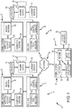
Figure 1 is a schematic representation of one arrangement of a system of operating a plurality of directional drilling rigs according to the present invention; -
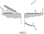
Figure 2 is a schematic representation of an exemplary drill site location showing an arrangement of a drilling rig, borehole, downhole probe, and above-ground coil; and -
Figure 3 depicts a flow chart of one embodiment of a method of operating a plurality of directional drilling rigs according to the present invention. - One arrangement of a system 10 for operating a plurality of directional drilling rigs is shown in
Figure 1 as it could be used to operate or control one or moredirectional drilling rigs 12 located at one or more drill sites orlocations 14. In the particular arrangements shown and described herein, the system 10 may be used to allow a single navigation technician orsystem navigator 16 to control at least certain portions of the operation (e.g., typically steering or navigation) of at least one, and generally a plurality, ofdirectional drilling rigs 12 located at the various locations ordrill sites 14. Further, thesystem navigator 16 exercises such control from asingle location 18 that is located remotely from the various drill sites orlocations 14. Thesystem navigator 16 utilizes aremote communications system 20 to send information or instructions to thedirectional drilling rigs 12 located at the variousdrill site locations 14. An on-site communications system 22 at thedrill site location 14 may receive information or instructions from theremote communications system 20. That information and/or instructions may be used to control at least certain aspects of the operation ofdirectional drilling rigs 12 located at the variousdrill site locations 14. In addition, certain information and/or instructions may be displayed to an on-site directional drill rig operator 24 (e.g., via on-site computer system 26). Thereafter, the on-site directionaldrill rig operator 24 may operate certain aspects or function of thedirectional drilling rig 12. - In some embodiments, the on-
site communications system 22 may continuously send or communicate data regarding the current position, status, and operation of eachdirectional drill rig 12 to the navigation technician orsystem navigator 16 at theremote location 18. Thesystem navigator 16 may use this real-time information to alter the drilling paths of thedirectional drill rigs 12 at the variousdrill site locations 14. In addition, the system navigator may communicate with the on-sitedrill rig operator 24 to convey additional instructions and/or authorizations to take certain actions, as will be described in further detail herein. - A significant advantage of the method of the present invention is the efficiency and logistical flexibility it offers. Previously, each on-site
drill rig operator 24 needed to possess the navigational skills and training of a navigation technician. The teachings of the present invention permit asingle system navigator 16 in aremote location 18 to provide this complex skillset to multipledrill site locations 14, thereby dispensing with the need to ensure that the on-sitedrill rig operator 24 possesses the required navigational skills. Furthermore, the present invention reduces the number of personnel who must be present on-site at a particulardrill site location 14, leading to transportation and logistical savings. Finally, the flexibility of the method of the present invention permits asingle system navigator 16 to 'move' from drill site to drill site nearly instantaneously, thereby permitting asingle system navigator 16 to simultaneously control a plurality ofdrilling rigs 12 performing a plurality of drilling jobs across the world. - Having briefly described the system 10 of operating one or more directional drill rigs from a remote location, various exemplary arrangements of the invention will now be described in detail.
- Referring back now to
Figure 1 , and as briefly described above, one arrangement of the system 10 of operating one or moredirectional drilling rigs 12 from aremote location 18 may comprise theremote location 18 and one or moredrill site locations 14. The directional drilling rig(s) 12 present at the drill site location(s) 14 may comprise any type of drilling machine as would be known in the art or as might be developed in the future that is capable of drilling a steerable drill string into the earth, controlling and modifying the path of the drill string as it drills deeper into the earth, and tracking the location of the drill head underground in order to ensure it remains on course. By way of non-limiting example, a wide variety of directional drilling rigs suitable for use with the present invention are commercially available from Ditch Witch Corporation of Perry, Oklahoma (US) and Vermeer Corporation of Pella, Iowa (US). Thedrill site locations 14 may be anywhere in the world, connected by thecommunications systems system navigator 16 at theremote location 18 may utilize theremote communications system 20 to send information or instructions to the variousdrill site locations 14. - In one arrangement, the
remote communications system 20 may comprise acontrol computer 28 that is connected to amodem 30 androuter 32 of the types commonly known in the art. Themodem 30 androuter 32 may enable thecontrol computer 28 to send and receive information via anetwork 34.Network 34 may comprise the Internet, a private network or VPN, or other network now known in the art or that may be developed in the future as would be suitable for permitting communications between the remote and on-site communications systems control computer 28 may comprise a computer device capable of running software, saving information for later retrieval, receiving input from a user, and sending and receiving electronic information over a network. By way of example, such acontrol computer 28 might comprise a desktop computer, portable laptop computer, tablet, smartphone, or a similar personal electronic device. Thecontrol computer 28 may be preloaded with directional drilling navigation software as would be familiar in the art, a Microsoft Office suite, or specialized remote control software. In an embodiment, thecontrol computer 28 may utilizerouter 32 to communicate with themodem 30 and thenetwork 34; alternatively, thecontrol computer 28 may communicate directly with themodem 30 to reach thenetwork 34. - The navigation technician or
system navigator 16 at theremote location 18 may input commands to thecontrol computer 28, which may send the commands using themodem 30 androuter 32 to thenetwork 34, and then on to thedrill site locations 14. To input these commands into thecontrol computer 28, the navigation technician orsystem navigator 16 may utilize aninput device 29, such as a keyboard and mouse, a touchscreen, or a joystick. Eachdrill site location 14 may contain an on-site communications system 22 to receive commands from theremote location 18. - In one arrangement, the on-
site communications system 22 may comprise awireless hotspot device 36, which receives the commands from theremote communications system 20 over thenetwork 34 and sends them to the on-site computer system 26. The on-site computer system 26 may comprise a computer device capable of running software, saving information for later retrieval, receiving input from a user, and sending and receiving electronic information over a network. By way of example, such an on-site computer 26 might comprise a desktop computer, portable laptop computer, tablet, smartphone, or a similar personal electronic device. In addition, either thecontrol computer 28 or the on-site computer 26, or both, may record and save all conversations between thesystem navigator 16 and on-site drill rig operator(s) 24, and may record a complete list of instructions or commands that are sent between the computers using theremote communications system 20 and the on-site communications system 22. Thewireless hotspot device 36 may be a cellular telephone or a stand-alone hotspot device of the type well known in the communications industry that can permit access to a network. In an arrangement, thewireless hotspot device 36 of the on-site communications system 22 may be operatively connected to amobile antenna 38, which maybe mounted todirectional drilling rig 12. Alternatively,antenna 38 may be provided elsewhere at thedrill site location 14 and may extend above the local tree line so as to maximize the signal. - When the on-
site communications system 22 receives instructions or information from theremote communications system 20, the on-site computer 26 may display the information to thedrill rig operator 24. Thedrill rig operator 24 may act on this information directly, and may use adrill control console 40 to manipulate the behavior of one or moredirectional drilling rigs 12 present at thedrill site location 14. In the particular arrangement shown and described herein, the on-site computer 26 is operatively connected to asteering tool receiver 42, which may be operatively connected todirectional drilling rig 12 at thedrill site location 14. This arrangement permits thesystem navigator 16 to issue steering commands to the on-site computer 26 using thecontrol computer 28, theremote communications system 20, and the on-site communications system 22. Thereafter, the on-sitedrill rig operator 24 may operate thedirectional drilling rig 12 in accordance with the issued steering commands. In an alternative arrangement, thesystem navigator 16 may use thecontrol computer 28,remote communications system 20, and on-site communications system to issue steering commands directly to thesteering tool receiver 42.Steering tool receiver 42 may then implement the steering instructions while the on-sitedrill rig operator 24 supervises thedrilling rig 12 activity. - The on-
site communications system 22 may send to theremote communications system 20 and controlcomputer 28 real-time telemetry and activity data regarding thedirectional drilling rigs 12 present at thedrill site 14. This will permit the navigation technician orsystem navigator 16 at theremote location 18 to monitor the activities of thedirectional drill rigs 12. This information may be continuously updated in real time, or may be updated at specifically defined time intervals, such as every minute, every five minutes, every thirty minutes, or any other interval of time. This flow of information may permit thesystem navigator 16 to adapt to changing conditions at thedrill site location 14 and redirect the activities of the directional drill rigs 12 accordingly. The flow of information also may allow the on-sitedrill rig operator 24 to continuously monitor the decisions of thesystem navigator 16 and provide feedback relating to on-site conditions or issues. - Referring now primarily to
Figure 2 , the information shared between theremote communication system 20 and on-site communications system 22 may permit thesystem navigator 16 and on-sitedrill rig operator 24 to coordinate their actions and perform complex drilling tasks. These tasks may include the taking of a survey shot, which may determine or verify the location of the borehole 52 by means of a below-grounddownhole probe 44 and an above-ground coil 46.Coil 46 may be operatively connected to asuitable power supply 48 andcurrent sensor 50. As is known in the art, an electric current flowing incoil 46 is detected by thedownhole probe 44, thereby allowing the position of thedownhole probe 44 to be determined. In one embodiment, thepower supply 48 may comprise an electric welding system, such as any of a wide range of welding systems commercially available from Miller Electric Manufacturing Company of Appleton, WI (US).Current sensor 50 may comprise any of a wide variety of ammeters and/or electrical multimeters commercially available from Fluke, Incorporated, of Everett, WA (US). - With reference now primarily to
Figure 3 , but with occasional reference toFigures 1 and2 , the system 10 may be configured to operate in accordance with amethod 52. Afirst step 54 ofmethod 52 may involve the collection of preliminary site data and the transfer of that preliminary site data to thesystem navigator 16. Preliminary site data include, but are not limited to data relating to topography of thedrill site 14, land features, centerlines, fault lines, GPS coordinates, the location and composition of known or potential underground obstructions, and the locations ofcoils 46. The on-sitedrill rig operator 24 may collect this preliminary site data and may transfer it to thesystem navigator 16 via the on-site communications system 22 andremote communications system 20. In an alternative embodiment, a separate survey technician present at thedrill site 14 may collect the preliminary site data and transfer it to thesystem navigator 16 via the on-site communications system 22 andremote communications system 20. - The on-site
drill rig operator 24 may prepare thedrilling rig 12 for drilling (e.g., performing a drilling job) atstep 56. In an alternative embodiment, thesystem navigator 16 may send preparation instructions directly to thedrilling rig 12 using the remote and on-site communications systems drilling rigs 12 that are scheduled to perform the jobs, steps 54 and 56 alternatively may be performed by various on-site drill rig crews at thevarious drill sites 14. - A
next step 58 ofmethod 52 involves the loading of data relating to the various drilling jobs into the navigation system and the creation of respective job files for the drilling jobs. The navigation system may comprise suitable directional drilling rig operation software that is provided on the on-site computer 26. Optionally, the drill rig operation software may also be provided oncontrol computer 28 atremote location 18. The drilling operation may be commenced atstep 60, in which various steering commands or drilling patterns (for example) may be transferred or otherwise conveyed to the on-sitedrill rig operator 24. As discussed herein, the various steering patterns may be developed by thesystem navigator 16 at theremote location 18. The steering commands or patterns are used by the on-sitedrill rig operator 24 to operate thedrilling rig 12. Of course, the on-sitedrill rig operator 24 may modify or otherwise alter the steering commands or patterns as thedrill rig operator 24 is actually on thedrill rig site 14 and maintains full control over thedrilling rig 12. - Depending on the nature of the drilling j ob, it may be desirable (or even required) to perform survey shots from time-to-time. Such survey shots may be used to track and/or update the location of the borehole 52 formed by the
drilling rig 12 to ensure proper navigation. Normally, the need for a survey shot will be determined by thesystem navigator 16. If thesystem navigator 16 determines that no survey shot is required (e.g., at step 62), then the drilling operation may proceed or continue (e.g., at step 64). Alternatively, if thesystem navigator 16 determines that a survey shot should be performed, then he or she may provide suitable instructions to the on-sitedrill rig operator 24 viacommunications systems drill rig operator 24 may perform the survey shot (at step 66). In one embodiment, the survey shot involves the use of thedownhole probe 44,coil 46,power supply 48 andcurrent sensor 50 to determine the location of thedownhole probe 44. - After the survey shot is performed, the survey shot data may be transferred or otherwise conveyed to the
system navigator 16 atstep 68. In one embodiment, the actual survey shot data is not per-se transferred, but is viewed by thedrill rig operator 24 on thecontrol computer 28 interfacing with the on-site computer 26; thedrill rig operator 24 may then communicate the data to thesystem navigator 16. Thesystem navigator 16 may review the survey shot data in view of various information, specifications, and parameters that may be associated with or relevant to the particular drilling job being performed. If the survey data are not approved atstep 70, e.g., because they are deficient in some regard, then thesystem navigator 16 may so inform the on-sitedrill rig operator 24. Thereafter, the on-sitedrill rig operator 24 may perform another survey shot (e.g., by repeating step 66). - Alternatively, if the
system navigator 16 approves the survey shot data, he or she may then instruct the on-sitedrill rig operator 24 to perform a reverse current survey shot atstep 72, as both forward and reverse current surveys are required to complete the location process. Thesystem navigator 16 may then review the reverse current survey data. If the reverse current data are acceptable, as determined duringstep 74, then thesystem navigator 16 may so inform the on-sitedrill rig operator 24 and theprocess 52 ends. Alternatively, if the reverse current survey data are not acceptable, then thesystem navigator 16 may instruct the on-sitedrill rig operator 24 to again perform the reverse current survey shot. - The
system navigator 16 may use theremote communications system 20 to rapidly switch between multipledrill site locations 14 throughout the world, each of which may contain one or multipledirectional drilling rigs 12, and continuously issue commands to the on-sitedrill rig operators 24 at eachdrill site location 14. The on-site communications systems 22 present at each of the separatedrill site locations 14 may continually keep thesystem navigator 16 informed of the activities of thedirectional drilling rigs 12 at the separatedrill site locations 14. - Having herein set forth preferred embodiments of the present invention, it is anticipated that suitable modifications can be made thereto which will nonetheless remain within the scope of the invention. The invention shall therefore only be construed in accordance with the following claims:
Claims (7)
- A method (52) of operating a plurality of directional drilling rigs (12) at different locations (14) under the supervision of a single off-site system navigator (16), comprising:
activating, at the location (18) of the off-site system navigator (16), a communications system (20) that connects the off-site system navigator (16) to at least the following:a first directional drilling rig (12) located at a first location (14) to perform a first drilling job; anda second directional drilling rig (12) located at a second location (14) to perform a second drilling job;collecting (54), at the first location (14), preliminary site data relating to the first drilling job to be performed by the first directional drilling rig (12);collecting, at the second location (14), preliminary site data relating to the second drilling job to be performed by the second directional drilling rig (12);transferring to the off-site system navigator (16) the preliminary site data for at least one of the first and second drilling jobs;preparing (56) at least one of the first and second directional drilling rigs (12) for the respective first and second drilling jobs;loading data (58) relating to at least one of the first and second drilling jobs into a navigation system operatively associated with the first and second directional drilling rigs (12);commencing the first drilling job;transferring steering patterns from the off-site system navigator (16) to an on-site drilling operator (24) for the first drilling job;operating the directional drilling rig (12) for the first drilling job in accordance with the transferred steering patterns;sending in-process directional drilling rig operation data, drill head location-tracking data, and on-site drilling operator communications from the first drilling job to the off-site system navigator (16);monitoring, at the location (18) of the off-site system navigator (16), the activity of the first drilling job;transferring (i) updated steering patterns relating to the in-process first drilling job, and (ii) off-site system navigator communications, from the off-site system navigator (16) to the on-site drilling operator (24) of the first drilling job;operating the directional drilling rig (12) for the first drilling job in accordance with the transferred updated steering patterns and under the continued supervision of the off-site system navigator (16); while simultaneously;commencing the second drilling job;transferring steering patterns from the off-site system navigator (16) to an on-site drilling operator (24) for the second commenced drilling job;operating the directional drilling rig (12) for the second drilling job in accordance with the transferred steering patterns;sending in-process directional drilling rig operation data, drill head location-tracking data, and on-site drilling operator communications from the second drilling job to the off-site system navigator (16);monitoring, at the location (18) of the off-site system navigator (16), the activity of the second drilling job;transferring (i) updated steering patterns relating to the in-process second drilling job, and (ii) off-site system navigator communications, from the off-site system navigator (16) to the on-site drilling operator (24) of the second drilling job; andoperating the directional drilling rig (12) for the second drilling job in accordance with the transferred updated steering patterns and under the continued supervision of the off-site system navigator (16). - The method (52) of claim 1, further comprising, for at least one of the first or second commenced drilling jobs:determining (62) whether a survey shot should be performed;if a survey shot should not be performed, then continuing drilling (64); and
if a survey shot should be performed, thenperforming (66) a first survey shot;transferring (68) to the off-site system navigator (16) survey data relating to the first survey shot; andreceiving an approval from the off-site system navigator (16) to perform a reverse current survey shot. - The method (52) of claim 2, further comprising, if no approval from the off-site system navigator (16) is received, then:performing (66) a second survey shot; andtransferring (68) to the off-site system navigator (16) survey data relating to the second survey shot.
- The method (52) of claim 2, further comprising, for the commenced drilling job:performing (72) a first reverse current survey shot;transferring to the off site system navigator (16) survey data relating to the first reverse current survey shot; andreceiving an approval from the off site system navigator (16) to terminate the commenced drilling job.
- The method (52) of claim 4, further comprising, if no approval from the off site system navigator (16) to terminate the commenced drilling job is received:performing (72) a second reverse current survey shot; andtransferring to the off site system navigator survey data relating to the second reverse current survey shot.
- The method (52) of claim 1, wherein said collecting (54) preliminary site data comprises collecting preliminary site data comprising one or more selected from the group consisting of topography, land features, centerlines, and coil locations; or wherein said collecting (54) preliminary site data for the first and second drilling jobs is conducted by first and second survey technicians at the first and second locations (14), respectively.
- The method of claim 1, wherein the on-site drilling operator (24) for the commenced drilling job conducts said preparing or conducts said operating.
Applications Claiming Priority (3)
| Application Number | Priority Date | Filing Date | Title |
|---|---|---|---|
| US201662294685P | 2016-02-12 | 2016-02-12 | |
| US15/365,009 US9957754B2 (en) | 2016-02-12 | 2016-11-30 | Systems and methods of operating directional drilling rigs |
| PCT/US2016/064407 WO2017139007A1 (en) | 2016-02-12 | 2016-12-01 | Systems and methods of operating directional drilling rigs |
Publications (3)
| Publication Number | Publication Date |
|---|---|
| EP3414426A1 EP3414426A1 (en) | 2018-12-19 |
| EP3414426A4 EP3414426A4 (en) | 2019-01-23 |
| EP3414426B1 true EP3414426B1 (en) | 2020-05-13 |
Family
ID=59561278
Family Applications (1)
| Application Number | Title | Priority Date | Filing Date |
|---|---|---|---|
| EP16890103.1A Active EP3414426B1 (en) | 2016-02-12 | 2016-12-01 | Systems and methods of operating directional drilling rigs |
Country Status (6)
| Country | Link |
|---|---|
| US (1) | US9957754B2 (en) |
| EP (1) | EP3414426B1 (en) |
| AU (1) | AU2016392577B2 (en) |
| CA (1) | CA3012175C (en) |
| MX (1) | MX393049B (en) |
| WO (1) | WO2017139007A1 (en) |
Families Citing this family (1)
| Publication number | Priority date | Publication date | Assignee | Title |
|---|---|---|---|---|
| CN116446791A (en) * | 2023-03-03 | 2023-07-18 | 国家能源集团乌海能源有限责任公司 | Underground directional drilling system for coal mine |
Family Cites Families (13)
| Publication number | Priority date | Publication date | Assignee | Title |
|---|---|---|---|---|
| US7269668B2 (en) | 2001-09-05 | 2007-09-11 | Redford Darrell J | Mobile, seamless, temporary, wireless network access apparatus and method |
| US7460957B2 (en) * | 2004-12-14 | 2008-12-02 | Schlumberger Technology Corporation | Geometrical optimization of multi-well trajectories |
| US20080125942A1 (en) | 2006-06-30 | 2008-05-29 | Page Tucker | System and method for digging navigation |
| US20080314641A1 (en) * | 2007-06-20 | 2008-12-25 | Mcclard Kevin | Directional Drilling System and Software Method |
| US20110297395A1 (en) | 2009-12-30 | 2011-12-08 | Schlumberger Technology Corporation | Remote drilling and completions management |
| US8616274B2 (en) | 2010-05-07 | 2013-12-31 | Halliburton Energy Services, Inc. | System and method for remote wellbore servicing operations |
| US9063248B2 (en) | 2011-06-10 | 2015-06-23 | International Business Machines Corporation | RTM seismic imaging using combined shot data |
| US9404356B2 (en) * | 2011-12-22 | 2016-08-02 | Motive Drilling Technologies, Inc. | System and method for remotely controlled surface steerable drilling |
| US8210283B1 (en) * | 2011-12-22 | 2012-07-03 | Hunt Energy Enterprises, L.L.C. | System and method for surface steerable drilling |
| US9512706B2 (en) | 2012-03-02 | 2016-12-06 | Schlumberger Technology Corporation | Agent registration in dynamic phase machine automation system |
| EP2834459A2 (en) | 2012-04-03 | 2015-02-11 | National Oilwell Varco, L.P. | Drilling control and information system |
| US20140379133A1 (en) * | 2013-06-21 | 2014-12-25 | Directional Control Systems International (DCSI) Inc. | Methods and systems for monitoring directional drilling |
| US20150138918A1 (en) | 2013-11-15 | 2015-05-21 | Cgg Services Sa | Seismic survey shot coordination apparatus method and system |
-
2016
- 2016-11-30 US US15/365,009 patent/US9957754B2/en active Active
- 2016-12-01 WO PCT/US2016/064407 patent/WO2017139007A1/en not_active Ceased
- 2016-12-01 CA CA3012175A patent/CA3012175C/en active Active
- 2016-12-01 AU AU2016392577A patent/AU2016392577B2/en active Active
- 2016-12-01 MX MX2018008952A patent/MX393049B/en unknown
- 2016-12-01 EP EP16890103.1A patent/EP3414426B1/en active Active
Non-Patent Citations (1)
| Title |
|---|
| None * |
Also Published As
| Publication number | Publication date |
|---|---|
| US20170234070A1 (en) | 2017-08-17 |
| CA3012175A1 (en) | 2017-08-17 |
| WO2017139007A1 (en) | 2017-08-17 |
| EP3414426A4 (en) | 2019-01-23 |
| US9957754B2 (en) | 2018-05-01 |
| AU2016392577A1 (en) | 2018-10-04 |
| AU2016392577B2 (en) | 2018-12-13 |
| CA3012175C (en) | 2019-02-19 |
| EP3414426A1 (en) | 2018-12-19 |
| MX393049B (en) | 2025-03-24 |
| MX2018008952A (en) | 2019-12-11 |
Similar Documents
| Publication | Publication Date | Title |
|---|---|---|
| AU2022271393B2 (en) | A method of, and a system for, controlling a drilling operation | |
| US11725484B2 (en) | Method of generating a drill hole sequence plan and drill hole sequence planning equipment | |
| US6910541B2 (en) | Macro assisted control system and method for a horizontal directional drilling machine | |
| CA2879806C (en) | Down-hole monitoring and survey system | |
| US20160047220A1 (en) | Drilling Planning System | |
| CN104141483B (en) | Digital drilling control method and system for surface deep hole blasting | |
| US8733473B2 (en) | Sequencing algorithm for planned drill holes | |
| US11585202B2 (en) | Method and system for optimizing field development | |
| US11555352B2 (en) | Multimode steering and homing system, method and apparatus | |
| CN109898991A (en) | For effectively transmitting the devices, systems, and methods of geosteering track adjustment | |
| CA2916434C (en) | Arrangement for controlling automated operation mode | |
| US11306563B2 (en) | Drilling rig communication systems, devices, and methods | |
| US10822941B2 (en) | Underground guidance using above-ground mesh network | |
| CN102713140A (en) | Remote drilling and completions management | |
| CA3012175C (en) | Systems and methods of operating directional drilling rigs | |
| Heredia et al. | Fully automated directional drilling is now a reality-an example from the Norwegian Continental Shelf | |
| US20240141772A1 (en) | Geosteering system | |
| Marino et al. | Innovative Drilling Strategy for Horizontal Wells in Triple Splitter Wellhead Arrangement: A Case Study From Rubiales Field in Colombia | |
| Obregón | GPS drill navigation and data collection in a mining environment |
Legal Events
| Date | Code | Title | Description |
|---|---|---|---|
| STAA | Information on the status of an ep patent application or granted ep patent |
Free format text: STATUS: THE INTERNATIONAL PUBLICATION HAS BEEN MADE |
|
| PUAI | Public reference made under article 153(3) epc to a published international application that has entered the european phase |
Free format text: ORIGINAL CODE: 0009012 |
|
| STAA | Information on the status of an ep patent application or granted ep patent |
Free format text: STATUS: REQUEST FOR EXAMINATION WAS MADE |
|
| 17P | Request for examination filed |
Effective date: 20180912 |
|
| AK | Designated contracting states |
Kind code of ref document: A1 Designated state(s): AL AT BE BG CH CY CZ DE DK EE ES FI FR GB GR HR HU IE IS IT LI LT LU LV MC MK MT NL NO PL PT RO RS SE SI SK SM TR |
|
| AX | Request for extension of the european patent |
Extension state: BA ME |
|
| A4 | Supplementary search report drawn up and despatched |
Effective date: 20190103 |
|
| RIC1 | Information provided on ipc code assigned before grant |
Ipc: E21B 44/00 20060101AFI20181219BHEP |
|
| DAV | Request for validation of the european patent (deleted) | ||
| DAX | Request for extension of the european patent (deleted) | ||
| STAA | Information on the status of an ep patent application or granted ep patent |
Free format text: STATUS: EXAMINATION IS IN PROGRESS |
|
| 17Q | First examination report despatched |
Effective date: 20190715 |
|
| GRAP | Despatch of communication of intention to grant a patent |
Free format text: ORIGINAL CODE: EPIDOSNIGR1 |
|
| STAA | Information on the status of an ep patent application or granted ep patent |
Free format text: STATUS: GRANT OF PATENT IS INTENDED |
|
| INTG | Intention to grant announced |
Effective date: 20191219 |
|
| GRAS | Grant fee paid |
Free format text: ORIGINAL CODE: EPIDOSNIGR3 |
|
| GRAA | (expected) grant |
Free format text: ORIGINAL CODE: 0009210 |
|
| STAA | Information on the status of an ep patent application or granted ep patent |
Free format text: STATUS: THE PATENT HAS BEEN GRANTED |
|
| AK | Designated contracting states |
Kind code of ref document: B1 Designated state(s): AL AT BE BG CH CY CZ DE DK EE ES FI FR GB GR HR HU IE IS IT LI LT LU LV MC MK MT NL NO PL PT RO RS SE SI SK SM TR |
|
| REG | Reference to a national code |
Ref country code: GB Ref legal event code: FG4D |
|
| REG | Reference to a national code |
Ref country code: CH Ref legal event code: EP |
|
| REG | Reference to a national code |
Ref country code: DE Ref legal event code: R096 Ref document number: 602016036597 Country of ref document: DE |
|
| REG | Reference to a national code |
Ref country code: AT Ref legal event code: REF Ref document number: 1270524 Country of ref document: AT Kind code of ref document: T Effective date: 20200615 |
|
| REG | Reference to a national code |
Ref country code: LT Ref legal event code: MG4D |
|
| REG | Reference to a national code |
Ref country code: NL Ref legal event code: MP Effective date: 20200513 |
|
| PG25 | Lapsed in a contracting state [announced via postgrant information from national office to epo] |
Ref country code: PT Free format text: LAPSE BECAUSE OF FAILURE TO SUBMIT A TRANSLATION OF THE DESCRIPTION OR TO PAY THE FEE WITHIN THE PRESCRIBED TIME-LIMIT Effective date: 20200914 Ref country code: IS Free format text: LAPSE BECAUSE OF FAILURE TO SUBMIT A TRANSLATION OF THE DESCRIPTION OR TO PAY THE FEE WITHIN THE PRESCRIBED TIME-LIMIT Effective date: 20200913 Ref country code: SE Free format text: LAPSE BECAUSE OF FAILURE TO SUBMIT A TRANSLATION OF THE DESCRIPTION OR TO PAY THE FEE WITHIN THE PRESCRIBED TIME-LIMIT Effective date: 20200513 Ref country code: NO Free format text: LAPSE BECAUSE OF FAILURE TO SUBMIT A TRANSLATION OF THE DESCRIPTION OR TO PAY THE FEE WITHIN THE PRESCRIBED TIME-LIMIT Effective date: 20200813 Ref country code: FI Free format text: LAPSE BECAUSE OF FAILURE TO SUBMIT A TRANSLATION OF THE DESCRIPTION OR TO PAY THE FEE WITHIN THE PRESCRIBED TIME-LIMIT Effective date: 20200513 Ref country code: GR Free format text: LAPSE BECAUSE OF FAILURE TO SUBMIT A TRANSLATION OF THE DESCRIPTION OR TO PAY THE FEE WITHIN THE PRESCRIBED TIME-LIMIT Effective date: 20200814 Ref country code: LT Free format text: LAPSE BECAUSE OF FAILURE TO SUBMIT A TRANSLATION OF THE DESCRIPTION OR TO PAY THE FEE WITHIN THE PRESCRIBED TIME-LIMIT Effective date: 20200513 |
|
| PG25 | Lapsed in a contracting state [announced via postgrant information from national office to epo] |
Ref country code: BG Free format text: LAPSE BECAUSE OF FAILURE TO SUBMIT A TRANSLATION OF THE DESCRIPTION OR TO PAY THE FEE WITHIN THE PRESCRIBED TIME-LIMIT Effective date: 20200813 Ref country code: LV Free format text: LAPSE BECAUSE OF FAILURE TO SUBMIT A TRANSLATION OF THE DESCRIPTION OR TO PAY THE FEE WITHIN THE PRESCRIBED TIME-LIMIT Effective date: 20200513 Ref country code: HR Free format text: LAPSE BECAUSE OF FAILURE TO SUBMIT A TRANSLATION OF THE DESCRIPTION OR TO PAY THE FEE WITHIN THE PRESCRIBED TIME-LIMIT Effective date: 20200513 Ref country code: RS Free format text: LAPSE BECAUSE OF FAILURE TO SUBMIT A TRANSLATION OF THE DESCRIPTION OR TO PAY THE FEE WITHIN THE PRESCRIBED TIME-LIMIT Effective date: 20200513 |
|
| REG | Reference to a national code |
Ref country code: AT Ref legal event code: MK05 Ref document number: 1270524 Country of ref document: AT Kind code of ref document: T Effective date: 20200513 |
|
| PG25 | Lapsed in a contracting state [announced via postgrant information from national office to epo] |
Ref country code: AL Free format text: LAPSE BECAUSE OF FAILURE TO SUBMIT A TRANSLATION OF THE DESCRIPTION OR TO PAY THE FEE WITHIN THE PRESCRIBED TIME-LIMIT Effective date: 20200513 Ref country code: NL Free format text: LAPSE BECAUSE OF FAILURE TO SUBMIT A TRANSLATION OF THE DESCRIPTION OR TO PAY THE FEE WITHIN THE PRESCRIBED TIME-LIMIT Effective date: 20200513 |
|
| PG25 | Lapsed in a contracting state [announced via postgrant information from national office to epo] |
Ref country code: CZ Free format text: LAPSE BECAUSE OF FAILURE TO SUBMIT A TRANSLATION OF THE DESCRIPTION OR TO PAY THE FEE WITHIN THE PRESCRIBED TIME-LIMIT Effective date: 20200513 Ref country code: RO Free format text: LAPSE BECAUSE OF FAILURE TO SUBMIT A TRANSLATION OF THE DESCRIPTION OR TO PAY THE FEE WITHIN THE PRESCRIBED TIME-LIMIT Effective date: 20200513 Ref country code: ES Free format text: LAPSE BECAUSE OF FAILURE TO SUBMIT A TRANSLATION OF THE DESCRIPTION OR TO PAY THE FEE WITHIN THE PRESCRIBED TIME-LIMIT Effective date: 20200513 Ref country code: SM Free format text: LAPSE BECAUSE OF FAILURE TO SUBMIT A TRANSLATION OF THE DESCRIPTION OR TO PAY THE FEE WITHIN THE PRESCRIBED TIME-LIMIT Effective date: 20200513 Ref country code: AT Free format text: LAPSE BECAUSE OF FAILURE TO SUBMIT A TRANSLATION OF THE DESCRIPTION OR TO PAY THE FEE WITHIN THE PRESCRIBED TIME-LIMIT Effective date: 20200513 Ref country code: DK Free format text: LAPSE BECAUSE OF FAILURE TO SUBMIT A TRANSLATION OF THE DESCRIPTION OR TO PAY THE FEE WITHIN THE PRESCRIBED TIME-LIMIT Effective date: 20200513 Ref country code: EE Free format text: LAPSE BECAUSE OF FAILURE TO SUBMIT A TRANSLATION OF THE DESCRIPTION OR TO PAY THE FEE WITHIN THE PRESCRIBED TIME-LIMIT Effective date: 20200513 Ref country code: IT Free format text: LAPSE BECAUSE OF FAILURE TO SUBMIT A TRANSLATION OF THE DESCRIPTION OR TO PAY THE FEE WITHIN THE PRESCRIBED TIME-LIMIT Effective date: 20200513 |
|
| REG | Reference to a national code |
Ref country code: DE Ref legal event code: R097 Ref document number: 602016036597 Country of ref document: DE |
|
| PG25 | Lapsed in a contracting state [announced via postgrant information from national office to epo] |
Ref country code: PL Free format text: LAPSE BECAUSE OF FAILURE TO SUBMIT A TRANSLATION OF THE DESCRIPTION OR TO PAY THE FEE WITHIN THE PRESCRIBED TIME-LIMIT Effective date: 20200513 Ref country code: SK Free format text: LAPSE BECAUSE OF FAILURE TO SUBMIT A TRANSLATION OF THE DESCRIPTION OR TO PAY THE FEE WITHIN THE PRESCRIBED TIME-LIMIT Effective date: 20200513 |
|
| PLBE | No opposition filed within time limit |
Free format text: ORIGINAL CODE: 0009261 |
|
| STAA | Information on the status of an ep patent application or granted ep patent |
Free format text: STATUS: NO OPPOSITION FILED WITHIN TIME LIMIT |
|
| 26N | No opposition filed |
Effective date: 20210216 |
|
| PG25 | Lapsed in a contracting state [announced via postgrant information from national office to epo] |
Ref country code: SI Free format text: LAPSE BECAUSE OF FAILURE TO SUBMIT A TRANSLATION OF THE DESCRIPTION OR TO PAY THE FEE WITHIN THE PRESCRIBED TIME-LIMIT Effective date: 20200513 |
|
| REG | Reference to a national code |
Ref country code: CH Ref legal event code: PL |
|
| PG25 | Lapsed in a contracting state [announced via postgrant information from national office to epo] |
Ref country code: MC Free format text: LAPSE BECAUSE OF FAILURE TO SUBMIT A TRANSLATION OF THE DESCRIPTION OR TO PAY THE FEE WITHIN THE PRESCRIBED TIME-LIMIT Effective date: 20200513 |
|
| REG | Reference to a national code |
Ref country code: BE Ref legal event code: MM Effective date: 20201231 |
|
| PG25 | Lapsed in a contracting state [announced via postgrant information from national office to epo] |
Ref country code: IE Free format text: LAPSE BECAUSE OF NON-PAYMENT OF DUE FEES Effective date: 20201201 Ref country code: LU Free format text: LAPSE BECAUSE OF NON-PAYMENT OF DUE FEES Effective date: 20201201 |
|
| PG25 | Lapsed in a contracting state [announced via postgrant information from national office to epo] |
Ref country code: LI Free format text: LAPSE BECAUSE OF NON-PAYMENT OF DUE FEES Effective date: 20201231 Ref country code: CH Free format text: LAPSE BECAUSE OF NON-PAYMENT OF DUE FEES Effective date: 20201231 |
|
| PG25 | Lapsed in a contracting state [announced via postgrant information from national office to epo] |
Ref country code: TR Free format text: LAPSE BECAUSE OF FAILURE TO SUBMIT A TRANSLATION OF THE DESCRIPTION OR TO PAY THE FEE WITHIN THE PRESCRIBED TIME-LIMIT Effective date: 20200513 Ref country code: MT Free format text: LAPSE BECAUSE OF FAILURE TO SUBMIT A TRANSLATION OF THE DESCRIPTION OR TO PAY THE FEE WITHIN THE PRESCRIBED TIME-LIMIT Effective date: 20200513 Ref country code: CY Free format text: LAPSE BECAUSE OF FAILURE TO SUBMIT A TRANSLATION OF THE DESCRIPTION OR TO PAY THE FEE WITHIN THE PRESCRIBED TIME-LIMIT Effective date: 20200513 |
|
| PG25 | Lapsed in a contracting state [announced via postgrant information from national office to epo] |
Ref country code: MK Free format text: LAPSE BECAUSE OF FAILURE TO SUBMIT A TRANSLATION OF THE DESCRIPTION OR TO PAY THE FEE WITHIN THE PRESCRIBED TIME-LIMIT Effective date: 20200513 |
|
| PG25 | Lapsed in a contracting state [announced via postgrant information from national office to epo] |
Ref country code: BE Free format text: LAPSE BECAUSE OF NON-PAYMENT OF DUE FEES Effective date: 20201231 |
|
| PGFP | Annual fee paid to national office [announced via postgrant information from national office to epo] |
Ref country code: GB Payment date: 20251229 Year of fee payment: 10 |
|
| PGFP | Annual fee paid to national office [announced via postgrant information from national office to epo] |
Ref country code: FR Payment date: 20251226 Year of fee payment: 10 |
|
| PGFP | Annual fee paid to national office [announced via postgrant information from national office to epo] |
Ref country code: DE Payment date: 20251229 Year of fee payment: 10 |