EP3414163B1 - Telescoping stowage tube and rotating hose reel for cargo bay refueling system - Google Patents
Telescoping stowage tube and rotating hose reel for cargo bay refueling system Download PDFInfo
- Publication number
- EP3414163B1 EP3414163B1 EP17750938.7A EP17750938A EP3414163B1 EP 3414163 B1 EP3414163 B1 EP 3414163B1 EP 17750938 A EP17750938 A EP 17750938A EP 3414163 B1 EP3414163 B1 EP 3414163B1
- Authority
- EP
- European Patent Office
- Prior art keywords
- hose
- stowage tube
- drum
- telescoping
- hose reel
- Prior art date
- Legal status (The legal status is an assumption and is not a legal conclusion. Google has not performed a legal analysis and makes no representation as to the accuracy of the status listed.)
- Active
Links
Images

Classifications
-
- B—PERFORMING OPERATIONS; TRANSPORTING
- B64—AIRCRAFT; AVIATION; COSMONAUTICS
- B64D—EQUIPMENT FOR FITTING IN OR TO AIRCRAFT; FLIGHT SUITS; PARACHUTES; ARRANGEMENT OR MOUNTING OF POWER PLANTS OR PROPULSION TRANSMISSIONS IN AIRCRAFT
- B64D39/00—Refuelling during flight
- B64D39/02—Means for paying-in or out hose
-
- B—PERFORMING OPERATIONS; TRANSPORTING
- B64—AIRCRAFT; AVIATION; COSMONAUTICS
- B64D—EQUIPMENT FOR FITTING IN OR TO AIRCRAFT; FLIGHT SUITS; PARACHUTES; ARRANGEMENT OR MOUNTING OF POWER PLANTS OR PROPULSION TRANSMISSIONS IN AIRCRAFT
- B64D39/00—Refuelling during flight
Definitions
- the present invention relates to a fuselage mounted aerial refueling system; and more particularly to a fuselage mounted aerial refueling system wherein the hose reel is secured to the fuselage while a stowage tube is secured to a movable door or ramp; and even more particularly to a fuselage mounted aerial refueling system wherein the hose reel is secured to the fuselage while a stowage tube is secured to a movable door or ramp, the stowage tube being configured to telescope between extended and retracted positions depending upon whether the movable door or ramp is in an open or closed orientation.
- Fuselage mounted refueling systems contain several common components regardless of the particular installation, including: a hose reel assembly to store and dispense a refueling hose, a stowage tube or other piece of equipment which holds the hose-end components when the system is not in use and guide the hose between the hose reel drum and the exit point through the aircraft skin or outer mold line (OML). Also included is a tunnel or other fixed location exit point where the hose passes through the OML and into the airstream.
- OML outer mold line
- hose reel assembly in a fixed orientation and location inside the fuselage and a single fixed exit point is provided through the aircraft OML.
- the hose reel and other components are mounted on a cargo door or ramp, moving together from the stowed position with the door or ramp closed into the refueling position when the door or ramp is lowered (opened).
- the ramp/door arrangement is peculiar to roll-on/roll-off type systems which are temporarily installed in multi-role aircraft.
- performance and reliability require that the hose remain tangential to the drum outside diameter during winding on/off.
- the hose drum equipment and the stowage tube/hose exit components are all mounted to the ramp to maintain the tangency described regardless of the ramp position or movement.
- US 2006/0065785 A1 discloses an in-flight hose-and-drogue aircraft refueling system composed of: a refueling hose-and-drogue unit extending from a refueling aircraft for engaging with a refueling probe of an aircraft to be refueled and a drogue steering assembly for steering the drogue.
- the hose-and-drogue unit is housed in a stowed position in a storage tube that opens to the exterior of the aircraft.
- a removable refueling system may be installed and anchored securely to the non-moving aircraft structure (fuselage) while having the exit point through the aircraft OML move up and down with door/ramp movement, all the while maintaining the tangency of the hose guide/stowage tube to the drum.
- the ability to mount the hose reel assembly and associated equipment to the floor or other fixed structure increases the allowable system weight, minimizes the effect and interaction of other equipment such as the ramp, and enhances system performance by minimizing vibration and other detrimental effects.
- a telescoping mechanism has been added to the stowage tube to address the issues resulting from the OML exit point moving as the door/ramp moves and the distance between the OML and the drum changes.
- a refueling system may allow the hose drum unit to rotate about the drum's central axis to thereby maintain tangency between the stowage tube and the drum O.D. during winding on/off of the hose.
- Several means could be employed to provide and control such rotation, such as but not limited to "slaving" the reel mounting hardware to the ramp door via a linkage to thereby insure that the drum will always be oriented for optimum performance as the door opens and closes.
- the present invention is generally directed to an aerial refueling system for refueling a receiver aircraft in flight from a fuel supply aircraft having a door movable between an open orientation and a closed orientation according to claim 1.
- the system comprises a hose reel assembly mounted onto the fuel supply aircraft's fuselage with the hose reel assembly having a rotatable drum defined by an outside diameter.
- a hose is wound around the drum and has an outlet end and a drogue affixed to the outlet end.
- a telescoping stowage tube is configured to store the outlet end of the hose and the drogue when the system is not in use and to guide the outlet end and the drogue toward the receiver aircraft when the system is in use.
- the telescoping stowage tube has a forward end configured to be mounted on the hose reel assembly to receive the hose from the drum and an aft end adapted to be mounted to the door.
- the telescoping stowage tube is extendable between a retracted stowed position when the door is in the closed orientation and an extended position when the door is in the open orientation.
- the telescoping stowage tube may include an outer housing slidably coupled to an inner housing and the hose within the telescoping stowage tube may lie along a plane tangential to the outside diameter of the drum.
- the hose reel assembly may also include a hose reel frame with the forward end of the telescoping stowage tube secured to the hose reel frame.
- the hose reel frame may pivot so as to maintain the tangential plane of the hose within the telescoping stowage tube relative to the outside diameter of the drum as the door moves between the open orientation and the closed orientation.
- the telescoping stowage tube may further translate along the hose reel frame in a plane parallel to the axis of rotation of the drum as the hose is wound off or wound onto the drum.
- the hose reel frame may include a lead screw and a serving gear nut may couple the forward end of the telescoping stowage tube to the lead screw.
- the serving gear nut may be configured to translate along the lead screw.
- the aerial refueling system may further include a stowage tube mount fixedly secured to the door at a first end and pivotally secured to the aft end of the telescoping stowage tube at a second end.
- the stowage tube mount may further include a swivel with the swivel configured to move the aft end of the telescoping stowage tube as the telescoping stowage tube translates along the hose reel frame.
- the drogue may remain within the telescoping stowage tube until the drum is rotated to unwind the hose whereby the hose further includes a spring configured to bias the drogue out of the aft end of the telescoping stowage tube as the drum is rotated to unwind the hose.
- V-22 V-22 Osprey cargo aircraft
- the refueling system is mounted to the cargo hold and lower cargo bay door, thereby converting the V-22 to a part-time tanker for refueling other aircraft.
- the telescoping stowage tube and rotating hose reel assembly of the present invention may be used on other platforms, such as weapon bay doors or other aircraft (commercial or military) having cargo bay doors where the system requires the stowage tube to be fixed to a rotating door and the hose reel assembly to be fixed to a permanent structural member of the aircraft.
- the telescoping stowage tube is required to safely eject the refueling assembly (i.e., drogue and refueling hose) into the airstream, with the maximum amount of clearance between the refueling assembly and aircraft structure.
- the hose reel assembly is mounted to a permanent structural member (e.g., the fuselage) and the telescoping stowage tube is mounted to the cargo bay door, the stowage tube angle changes as the cargo door opens and closes.
- This stowage tube angle change requires the stowage tube to extend while the door is down (open) for trail (unwind) and rewind hose reel operations so as to maintain a tangential relationship between the hose within the telescoping stowage tube and the hose reel drum.
- the stowage tube angle should match the natural catenary angle of the refueling hose so that all hose tension changes are transferred through the hose reel assembly, such as through the torque arm and boost cylinder of the hose reel assembly.
- the aircraft has a safety requirement that both the upper and lower cargo bay doors must be closed if the personnel in the cabin are required to ditch the aircraft (i.e., attempt to perform a controlled landing of the disabled or distressed aircraft).
- This safety requirement drives an additional mechanism to allow for further telescoping of the stowage tube assembly. That is, when the lower cargo door is in the up (closed) orientation, the aft end of the stowage tube must be forward of the cargo bay door so that the upper cargo bay door can fully close prior to ditching.
- the aft end of the stowage tube must be aft of the lower cargo bay door to ensure no contact is made with the door or other aircraft component during the trailing (unwinding) or the rewinding of the refueling hose.
- this actuation may be performed by, and without limitation solely thereto, a linear actuator, springs, cables and/or linkages slaved to the lower cargo bay door.
- Aerial refueling system 10 is generally comprised of a hose reel assembly 12 mounted to a structural component of the fuel supply aircraft 13, such as fuselage 14.
- Hose reel assembly 12 includes a rotatable drum 16 defined by an outside diameter 18.
- Hose 20 is wound around drum 16 as is known in the art (see also FIG. 4 ).
- aft end 22 of hose 20 is configured to carry a drogue refueling assembly 24 with inflatable drogue 26.
- Telescoping stowage tube 28 Prior to ejection of drogue refueling assembly 24 during refueling operations or when aerial refueling system 10 is in a stowed condition (such as shown in FIG. 1 ), a portion of hose 20, including aft end 22 and drogue refueling assembly 24, is stored within telescoping stowage tube 28.
- Telescoping stowage tube 28 includes a forward end 30 configured to be mounted onto hose reel assembly 12 to receive hose 20 from drum 16 and an aft end 32 adapted to be mounted to a door/ramp of aircraft 13, such as cargo bay door 34.
- aft end 32 may be pivotally mounted to stowage tube mount 36 at pivot 38. In this manner, aft end 32 (and thus telescoping stowage tube 28) may pivot as cargo bay door 34 reciprocates between the closed orientation ( FIG. 1 ) and the open orientation ( FIGS. 2-3 ).
- telescoping stowage tube 28 comprises an outer housing 40 slidably coupled to inner housing 42.
- the length of telescoping stowage tube 28 may change, as will be discussed in greater detail below.
- telescoping stowage tube may be constructed in any suitable form.
- the sliding engagement of outer housing 40 with inner housing 42 is sufficiently rigid to accommodate lateral stresses exerted upon telescoping stowage tube 28 during use.
- cargo bay door 34 moves from the closed orientation ( FIG. 1 ) to an open orientation ( FIGS. 2-3 ).
- telescoping stowage tube 28 extends generally in the direction indicated by arrow 48 from a retracted stowed position ( FIG. 1 ) to an extended position ( FIGS. 2-3 ) as described above.
- hose 20 may be unwound from drum 16 to direct refueling assembly 24 and drogue 26 in the trail position (i.e., extending outwardly from fuel supply aircraft 13 so as to safely couple with the receiver aircraft (not shown)) as is known in the art.
- hose 20 may include a spring 50 which is fully compressed in the stowed position to bias refueling assembly 24 and drogue 26 out exit orifice 52 defined by terminus of aft end 32 of telescoping stowage tube 28.
- spring bias of spring 50 is maintained due to hose 20 being wound about drum 16.
- hose 20 is commanded to the trail position after cargo bay door 34 has been opened and telescoping stowage tube 28 has been extended ( FIGS.
- drum 16 will rotate in the trail direction at a fixed speed to eject hose 20 through telescoping stowage tube 28.
- the bias stored within spring 50 will operate to push refueling assembly 24 and drogue 26 towards exit orifice 52. Once refueling assembly 24 reaches the airstream, drogue 26 will inflate and create drag on hose 20 while drogue 26 and hose 20 extend outwardly from fuel supply aircraft 13 toward the full trail position.
- hose reel assembly 12 is mounted to fuselage 14 and aft end 32 of telescoping stowage tube 28 is mounted to cargo bay 34, the stowage tube angle changes as cargo bay door 34 opens and closes (compare angle A in FIG. 1 with angle A' in FIG. 2 ).
- hose reel assembly 12 may be configured to rotate as cargo bay door 34 pivots about hinge 44 so as to keep the relative angle B between telescoping stowage tube 28 and hose reel assembly 12 substantially the same throughout movement of cargo bay door 34 and hose reel assembly 12.
- hose reel assembly 12 may include a hose reel frame 54 pivotally mounted onto mounting frame 56 of hose reel assembly 12.
- Pivoting control of hose reel frame 54 may be slaved to pivoting control of cargo bay door 34 such that angle B is maintained as cargo bay door 34 opens and telescoping stowage tube 28 extends from its retracted stowed position to the extended position as described above.
- hose 20 may remain in a plane P that is tangential to outside diameter 18 of drum 16.
- hose wear properties may be improved and hose tension changes may be transferred through the structural components of hose reel assembly 12, such as though torque arm 58 and boost cylinder 60 (see FIG. 4 ).
- drum 16 of hose reel assembly 12 will rotate around the fuel inlet (not shown) so that hard lines can be used to couple aerial refueling system 10 with a fuel storage tank (not shown) without any fuel leaks.
- hose reel frame 54 may include a lead screw 62 and serving gear nut 64 whereby forward end 30 of telescoping stowage tube 28 may be mounted to serving gear nut 64.
- Serving gear 64 is configured to translate along lead screw 62 as lead screw 62 is rotated.
- Lead screw 62 may be slaved to drum 16 rotator control such that gear nut 64 and forward end 30 of telescoping stowage tube 28 translate orthogonally to the winding/unwinding hose 20 from drum 16. Orthogonal translation of telescoping stowage tube 28 permits proper unwinding/rewinding of hose 20 onto drum 16.
- stowage tube mount 36 may include a swivel 66 configured to permit movement of aft end 32 as forward end 30 translates.
Landscapes
- Engineering & Computer Science (AREA)
- Aviation & Aerospace Engineering (AREA)
- Loading And Unloading Of Fuel Tanks Or Ships (AREA)
- Storing, Repeated Paying-Out, And Re-Storing Of Elongated Articles (AREA)
Description
- The present invention relates to a fuselage mounted aerial refueling system; and more particularly to a fuselage mounted aerial refueling system wherein the hose reel is secured to the fuselage while a stowage tube is secured to a movable door or ramp; and even more particularly to a fuselage mounted aerial refueling system wherein the hose reel is secured to the fuselage while a stowage tube is secured to a movable door or ramp, the stowage tube being configured to telescope between extended and retracted positions depending upon whether the movable door or ramp is in an open or closed orientation.
- Fuselage mounted refueling systems contain several common components regardless of the particular installation, including: a hose reel assembly to store and dispense a refueling hose, a stowage tube or other piece of equipment which holds the hose-end components when the system is not in use and guide the hose between the hose reel drum and the exit point through the aircraft skin or outer mold line (OML). Also included is a tunnel or other fixed location exit point where the hose passes through the OML and into the airstream.
- Currently deployed systems generally fall into one of two categories depending on whether the equipment is mounted in the fuselage or on a movable door or ramp. In the former instance, existing systems include a hose reel assembly in a fixed orientation and location inside the fuselage and a single fixed exit point is provided through the aircraft OML. In the latter arrangement, the hose reel and other components are mounted on a cargo door or ramp, moving together from the stowed position with the door or ramp closed into the refueling position when the door or ramp is lowered (opened).
- The ramp/door arrangement is peculiar to roll-on/roll-off type systems which are temporarily installed in multi-role aircraft. On any system incorporating a hose and some sort of drum to wind it on and off, performance and reliability require that the hose remain tangential to the drum outside diameter during winding on/off. On the ramp type systems described above, the hose drum equipment and the stowage tube/hose exit components are all mounted to the ramp to maintain the tangency described regardless of the ramp position or movement.
- Further technological background can be found in
US 2006/065785 A1 ,US 2006/000950 A1 ,EP 2 933 656 A1 ,WO 2007/044021 A1 andUS 2007/181748 A1 DocumentUS 2006/0065785 A1 discloses an in-flight hose-and-drogue aircraft refueling system composed of: a refueling hose-and-drogue unit extending from a refueling aircraft for engaging with a refueling probe of an aircraft to be refueled and a drogue steering assembly for steering the drogue. In one embodiment the hose-and-drogue unit is housed in a stowed position in a storage tube that opens to the exterior of the aircraft. - A serious limitation inherent in such systems to date, however, is the capacity of the ramp to support the size and weight of the entire refueling system in flight and in use. Further performance limitations result from the lack of structural rigidity inherent in a moving door or ramp, such as increased vibration and high loads created by hose tension being applied to the ramp or door rather than solid aircraft structure like the cargo bay floor.
- A removable refueling system may be installed and anchored securely to the non-moving aircraft structure (fuselage) while having the exit point through the aircraft OML move up and down with door/ramp movement, all the while maintaining the tangency of the hose guide/stowage tube to the drum. The ability to mount the hose reel assembly and associated equipment to the floor or other fixed structure increases the allowable system weight, minimizes the effect and interaction of other equipment such as the ramp, and enhances system performance by minimizing vibration and other detrimental effects. To that end, a telescoping mechanism has been added to the stowage tube to address the issues resulting from the OML exit point moving as the door/ramp moves and the distance between the OML and the drum changes.
- A refueling system may allow the hose drum unit to rotate about the drum's central axis to thereby maintain tangency between the stowage tube and the drum O.D. during winding on/off of the hose. Several means could be employed to provide and control such rotation, such as but not limited to "slaving" the reel mounting hardware to the ramp door via a linkage to thereby insure that the drum will always be oriented for optimum performance as the door opens and closes.
- Accordingly, the present invention is generally directed to an aerial refueling system for refueling a receiver aircraft in flight from a fuel supply aircraft having a door movable between an open orientation and a closed orientation according to claim 1. The system comprises a hose reel assembly mounted onto the fuel supply aircraft's fuselage with the hose reel assembly having a rotatable drum defined by an outside diameter. A hose is wound around the drum and has an outlet end and a drogue affixed to the outlet end. A telescoping stowage tube is configured to store the outlet end of the hose and the drogue when the system is not in use and to guide the outlet end and the drogue toward the receiver aircraft when the system is in use. The telescoping stowage tube has a forward end configured to be mounted on the hose reel assembly to receive the hose from the drum and an aft end adapted to be mounted to the door. As a result, the telescoping stowage tube is extendable between a retracted stowed position when the door is in the closed orientation and an extended position when the door is in the open orientation.
- Additionally, the telescoping stowage tube may include an outer housing slidably coupled to an inner housing and the hose within the telescoping stowage tube may lie along a plane tangential to the outside diameter of the drum. The hose reel assembly may also include a hose reel frame with the forward end of the telescoping stowage tube secured to the hose reel frame. Thus, the hose reel frame may pivot so as to maintain the tangential plane of the hose within the telescoping stowage tube relative to the outside diameter of the drum as the door moves between the open orientation and the closed orientation. The telescoping stowage tube may further translate along the hose reel frame in a plane parallel to the axis of rotation of the drum as the hose is wound off or wound onto the drum. To that end, the hose reel frame may include a lead screw and a serving gear nut may couple the forward end of the telescoping stowage tube to the lead screw. The serving gear nut may be configured to translate along the lead screw.
- Still further, the aerial refueling system may further include a stowage tube mount fixedly secured to the door at a first end and pivotally secured to the aft end of the telescoping stowage tube at a second end. The stowage tube mount may further include a swivel with the swivel configured to move the aft end of the telescoping stowage tube as the telescoping stowage tube translates along the hose reel frame. The drogue may remain within the telescoping stowage tube until the drum is rotated to unwind the hose whereby the hose further includes a spring configured to bias the drogue out of the aft end of the telescoping stowage tube as the drum is rotated to unwind the hose.
- Additional objects, advantages and novel aspects of the present invention will be set forth in part in the description which follows, and will in part become apparent to those in the practice of the invention, when considered with the attached figures.
- The above-mentioned and other features are advantages of this invention, and the manner of attaining them, will become apparent and be better understood by reference to the following description of the invention in conjunction with the accompanying drawings, wherein:
-
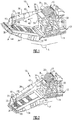
FIG. 1 is a partial schematic view of a refueling system in accordance with the present invention showing the refueling system in a stowed configuration; -
FIG. 2 is a partial schematic view of the refueling system shown inFIG. 1 showing the refueling system in a trailing configuration; -
FIG. 3 is a cross section view of the refueling system shown inFIG. 2 with the drogue partially ejected from the telescoping stowage tube; and -
FIG. 4 is an expanded partial view of a hose reel assembly using within the refueling system shown inFIG. 1 . - The following describes a specific application of a general aerial refueling system of the present invention on the V-22 Osprey cargo aircraft (the "V-22") wherein the refueling system is mounted to the cargo hold and lower cargo bay door, thereby converting the V-22 to a part-time tanker for refueling other aircraft. While shown and described with reference to the V-22, it should be understood by those skilled in the art that the telescoping stowage tube and rotating hose reel assembly of the present invention may be used on other platforms, such as weapon bay doors or other aircraft (commercial or military) having cargo bay doors where the system requires the stowage tube to be fixed to a rotating door and the hose reel assembly to be fixed to a permanent structural member of the aircraft.
- As will be discussed in greater detail below, the telescoping stowage tube is required to safely eject the refueling assembly (i.e., drogue and refueling hose) into the airstream, with the maximum amount of clearance between the refueling assembly and aircraft structure. Because the hose reel assembly is mounted to a permanent structural member (e.g., the fuselage) and the telescoping stowage tube is mounted to the cargo bay door, the stowage tube angle changes as the cargo door opens and closes. This stowage tube angle change requires the stowage tube to extend while the door is down (open) for trail (unwind) and rewind hose reel operations so as to maintain a tangential relationship between the hose within the telescoping stowage tube and the hose reel drum. To that end, the stowage tube angle should match the natural catenary angle of the refueling hose so that all hose tension changes are transferred through the hose reel assembly, such as through the torque arm and boost cylinder of the hose reel assembly.
- In the case of the V-22, the aircraft has a safety requirement that both the upper and lower cargo bay doors must be closed if the personnel in the cabin are required to ditch the aircraft (i.e., attempt to perform a controlled landing of the disabled or distressed aircraft). This safety requirement drives an additional mechanism to allow for further telescoping of the stowage tube assembly. That is, when the lower cargo door is in the up (closed) orientation, the aft end of the stowage tube must be forward of the cargo bay door so that the upper cargo bay door can fully close prior to ditching. However, when the lower cargo bay door is in the down (open) orientation, such as in preparation for and during refueling operations, the aft end of the stowage tube must be aft of the lower cargo bay door to ensure no contact is made with the door or other aircraft component during the trailing (unwinding) or the rewinding of the refueling hose. As will be described in more detail below, this actuation may be performed by, and without limitation solely thereto, a linear actuator, springs, cables and/or linkages slaved to the lower cargo bay door.
- Turning now to the figures, and with specific reference to
FIGS. 1-3 , an aerial refueling system in accordance with the present invention is indicated byreference numeral 10.Aerial refueling system 10 is generally comprised of ahose reel assembly 12 mounted to a structural component of thefuel supply aircraft 13, such asfuselage 14.Hose reel assembly 12 includes arotatable drum 16 defined by anoutside diameter 18.Hose 20 is wound arounddrum 16 as is known in the art (see alsoFIG. 4 ). As can be seen most clearly inFIG. 3 ,aft end 22 ofhose 20 is configured to carry adrogue refueling assembly 24 withinflatable drogue 26. Prior to ejection ofdrogue refueling assembly 24 during refueling operations or whenaerial refueling system 10 is in a stowed condition (such as shown inFIG. 1 ), a portion ofhose 20, includingaft end 22 anddrogue refueling assembly 24, is stored withintelescoping stowage tube 28.Telescoping stowage tube 28 includes a forward end 30 configured to be mounted ontohose reel assembly 12 to receivehose 20 fromdrum 16 and anaft end 32 adapted to be mounted to a door/ramp ofaircraft 13, such ascargo bay door 34. To that end,aft end 32 may be pivotally mounted tostowage tube mount 36 atpivot 38. In this manner, aft end 32 (and thus telescoping stowage tube 28) may pivot ascargo bay door 34 reciprocates between the closed orientation (FIG. 1 ) and the open orientation (FIGS. 2-3 ). - In one aspect of the invention,
telescoping stowage tube 28 comprises anouter housing 40 slidably coupled toinner housing 42. In this manner, the length oftelescoping stowage tube 28 may change, as will be discussed in greater detail below. It should be noted that, while being shown and described as overlapping concentric housings in sliding arrangement, telescoping stowage tube may be constructed in any suitable form. However, the sliding engagement ofouter housing 40 withinner housing 42 is sufficiently rigid to accommodate lateral stresses exerted upon telescopingstowage tube 28 during use. - When deploying
aerial refueling system 10 for inflight refueling operations,cargo bay door 34 moves from the closed orientation (FIG. 1 ) to an open orientation (FIGS. 2-3 ). Ascargo bay door 34 pivots about hinge 44 (generally in the direction indicated by arrow 46),telescoping stowage tube 28 extends generally in the direction indicated byarrow 48 from a retracted stowed position (FIG. 1 ) to an extended position (FIGS. 2-3 ) as described above. With telescopingstowage tube 28 in its fully extended position,hose 20 may be unwound fromdrum 16 to directrefueling assembly 24 anddrogue 26 in the trail position (i.e., extending outwardly fromfuel supply aircraft 13 so as to safely couple with the receiver aircraft (not shown)) as is known in the art. - With reference to
FIG. 3 , to ejectrefueling assembly 24 anddrogue 26 throughtelescoping stowage tube 28,hose 20 may include aspring 50 which is fully compressed in the stowed position to biasrefueling assembly 24 anddrogue 26 outexit orifice 52 defined by terminus ofaft end 32 oftelescoping stowage tube 28. When in the stowed position (FIG. 1 ), spring bias ofspring 50 is maintained due tohose 20 being wound aboutdrum 16. However, whenhose 20 is commanded to the trail position aftercargo bay door 34 has been opened andtelescoping stowage tube 28 has been extended (FIGS. 2-3 ),drum 16 will rotate in the trail direction at a fixed speed to ejecthose 20 throughtelescoping stowage tube 28. The bias stored withinspring 50 will operate to pushrefueling assembly 24 anddrogue 26 towardsexit orifice 52. Once refuelingassembly 24 reaches the airstream,drogue 26 will inflate and create drag onhose 20 whiledrogue 26 andhose 20 extend outwardly fromfuel supply aircraft 13 toward the full trail position. - Because
hose reel assembly 12 is mounted tofuselage 14 andaft end 32 oftelescoping stowage tube 28 is mounted tocargo bay 34, the stowage tube angle changes ascargo bay door 34 opens and closes (compare angle A inFIG. 1 with angle A' inFIG. 2 ). To accommodate stowage tube angle changes,hose reel assembly 12 may be configured to rotate ascargo bay door 34 pivots abouthinge 44 so as to keep the relative angle B betweentelescoping stowage tube 28 andhose reel assembly 12 substantially the same throughout movement ofcargo bay door 34 andhose reel assembly 12. To that end,hose reel assembly 12 may include ahose reel frame 54 pivotally mounted onto mountingframe 56 ofhose reel assembly 12. Pivoting control ofhose reel frame 54 may be slaved to pivoting control ofcargo bay door 34 such that angle B is maintained ascargo bay door 34 opens andtelescoping stowage tube 28 extends from its retracted stowed position to the extended position as described above. In this manner,hose 20 may remain in a plane P that is tangential tooutside diameter 18 ofdrum 16. By maintaininghose 20 in a tangential plane relative tooutside diameter 18, hose wear properties may be improved and hose tension changes may be transferred through the structural components ofhose reel assembly 12, such as thoughtorque arm 58 and boost cylinder 60 (seeFIG. 4 ). In one aspect of the present invention, drum 16 ofhose reel assembly 12 will rotate around the fuel inlet (not shown) so that hard lines can be used to coupleaerial refueling system 10 with a fuel storage tank (not shown) without any fuel leaks. - With reference to
FIG. 4 ,hose reel frame 54 may include a lead screw 62 and servinggear nut 64 whereby forward end 30 oftelescoping stowage tube 28 may be mounted to servinggear nut 64. Servinggear 64 is configured to translate along lead screw 62 as lead screw 62 is rotated. Lead screw 62 may be slaved to drum 16 rotator control such thatgear nut 64 and forward end 30 oftelescoping stowage tube 28 translate orthogonally to the winding/unwindinghose 20 fromdrum 16. Orthogonal translation oftelescoping stowage tube 28 permits proper unwinding/rewinding ofhose 20 ontodrum 16. To prevent or minimize lateral stresses to telescopingstowage tube 28 during orthogonal translation of forward end 30,stowage tube mount 36 may include aswivel 66 configured to permit movement ofaft end 32 as forward end 30 translates. - Although the invention has been described with reference to preferred embodiments thereof, it is understood that various modifications may be made thereto. While specific reference has been made to rotational movements of device components, it should be understood by those skilled in the art that such rotations may be reversed and that such teachings are within the scope of the present invention.
Claims (10)
- An aerial refueling system (10) for refueling a receiver aircraft in flight from a fuel supply aircraft (13) having a door (34) movable between an open orientation and a closed orientation, the system (10) comprising:a) a hose reel assembly (12) configured to be mounted onto a fuselage (14) of the fuel supply aircraft (13), the hose reel assembly (12) including a rotatable drum (16), the drum (16) defined by an outside diameter;b) a hose (20) wound around the drum (16) of the hose reel assembly (12), the hose (20) having an outlet end and a drogue (26) affixed to the outlet end; characterized in that the aerial refueling system (10) further comprisesc) a telescoping stowage tube (28) configured to store the outlet end of the hose (20) and the drogue (26) when the system (10) is not in use and to guide the outlet end and the drogue (26) toward the receiver aircraft when the system (10) is in use, the telescoping stowage tube (28) having a forward end (30) configured to be mounted on the hose reel assembly (12) to receive the hose (20) from the drum (16) and an aft end (32) adapted to be mounted to the door (34),whereby, the telescoping stowage tube (28) is configured to extend between a retracted stowed position when the door (34) is in the closed orientation and an extended position when the door (34) is in the open orientation.
- The aerial refueling system (10) of claim 1 wherein the telescoping stowage tube (28) includes an outer housing (40) slidably coupled to an inner housing (42).
- The aerial refueling system (10) of claim 1 wherein the hose (20) within the telescoping stowage tube (28) lies along a plane tangential to the outside diameter of the drum (16).
- The aerial refueling system (10) of claim 3 wherein the hose reel assembly (12) includes a hose reel frame (54) pivotally mounted thereto, the forward end (30) of the telescoping stowage tube (28) secured to the hose reel frame (54) whereby the hose reel frame (54) is configured to pivot so as to maintain the tangential plane of the hose (20) within the telescoping stowage tube (28) relative to the outside diameter of the drum (16) as the door (34) moves between the open orientation and the closed orientation.
- The aerial refueling system (10) of claim 4 wherein the telescoping stowage tube (28) translates along the hose reel frame (54) in a plane parallel to the axis of rotation of the drum (16) as the hose (20) is wound off or wound onto the drum (16).
- The aerial refueling system (10) of claim 5 wherein the hose reel frame (54) includes a lead screw (62) and a serving gear nut (64) couples the forward end (30) of the telescoping stowage tube (28) to the lead screw (62), the serving gear nut (64) configured to translate along the lead screw (62) to move the forward end (30) of the telescoping stowage tube (28) as the drum (16) rotates to wind off or wind on the hose (20).
- The aerial refueling system (10) of claim 1 further comprising:
d) a stowage tube mount (36) configured to be fixedly secured to the door (34) at a first end and pivotally secured to the aft end (32) of the telescoping stowage tube (28) at a second end. - The aerial refueling system (10) of claim 5 further comprising:
d) a stowage tube mount (36) configured to be fixedly secured to the door (34) at a first end and pivotally secured to the aft end (32) of the telescoping stowage tube (28) at a second end, the stowage tube mount (36) further including a swivel (66), the swivel (66) configured to move the aft end (32) of the telescoping stowage tube (28) as the telescoping stowage tube (28) translates along the hose reel frame (54). - The aerial refueling system (10) of claim 1 wherein the drogue (26) remains within the telescoping stowage tube (28) until the drum (16) is rotated to unwind the hose (20).
- The aerial refueling system (10) of claim 9 wherein the telescoping stowage tube (28) further includes a stowage spring configured to bias the drogue (26) out of the aft end (32) of the telescoping stowage tube (28) as the drum (16) is rotated to unwind the hose (20).
Applications Claiming Priority (2)
| Application Number | Priority Date | Filing Date | Title |
|---|---|---|---|
| US201662294622P | 2016-02-12 | 2016-02-12 | |
| PCT/US2017/017602 WO2017139730A1 (en) | 2016-02-12 | 2017-02-13 | Telescoping stowage tube and rotating hose reel for cargo bay refueling system |
Publications (3)
| Publication Number | Publication Date |
|---|---|
| EP3414163A1 EP3414163A1 (en) | 2018-12-19 |
| EP3414163A4 EP3414163A4 (en) | 2019-09-25 |
| EP3414163B1 true EP3414163B1 (en) | 2020-12-30 |
Family
ID=59559551
Family Applications (1)
| Application Number | Title | Priority Date | Filing Date |
|---|---|---|---|
| EP17750938.7A Active EP3414163B1 (en) | 2016-02-12 | 2017-02-13 | Telescoping stowage tube and rotating hose reel for cargo bay refueling system |
Country Status (5)
| Country | Link |
|---|---|
| US (1) | US10384798B2 (en) |
| EP (1) | EP3414163B1 (en) |
| JP (1) | JP7021423B2 (en) |
| PT (1) | PT3414163T (en) |
| WO (1) | WO2017139730A1 (en) |
Families Citing this family (4)
| Publication number | Priority date | Publication date | Assignee | Title |
|---|---|---|---|---|
| CN109279036A (en) * | 2018-10-13 | 2019-01-29 | 左红 | Air refuelling equipment and its installation method |
| EP3715815B1 (en) | 2019-04-08 | 2023-03-29 | Airbus Defence and Space, S.A.U. | System and method for monitoring the degradation status of refueling hoses |
| US11691753B2 (en) * | 2019-11-11 | 2023-07-04 | Textron Innovations Inc. | Systems and methods for aerial aircraft resupply |
| CN112896533A (en) * | 2021-03-12 | 2021-06-04 | 中航西飞民用飞机有限责任公司 | Airplane refueling rod system and refueling method |
Family Cites Families (15)
| Publication number | Priority date | Publication date | Assignee | Title |
|---|---|---|---|---|
| US2879017A (en) | 1955-01-25 | 1959-03-24 | Flight Refueling Inc | Apparatus for interconnecting aircraft in flight |
| US2973163A (en) | 1956-02-03 | 1961-02-28 | Flight Refueling Inc | Apparatus for trailing a fluid-transmitting hose or tow-line from an aircraft |
| US2995321A (en) | 1958-07-15 | 1961-08-08 | Flight Refueling Inc | Fluid transfer systems |
| US3674049A (en) | 1970-09-18 | 1972-07-04 | Flight Refueling Ltd | Air-to-air refuelling hose reels |
| US4905937A (en) * | 1988-10-07 | 1990-03-06 | The Boeing Company | Pod assembly with integrated radiofrequency emitting and aerial refueling equipment |
| FR2648428B1 (en) | 1989-06-15 | 1993-09-17 | Aerospatiale | AUTONOMOUS DEVICE FOR THE DELIVERY OF A PRODUCT FROM AN AIRCRAFT |
| US5393015A (en) * | 1993-06-01 | 1995-02-28 | Piasecki Aircraft Corporation | Rotary wing aircraft in-flight refueling device |
| US6926049B1 (en) | 2002-08-23 | 2005-08-09 | Uav Refueling Inc. | Hose-and-drogue in-flight refueling system |
| US7185854B2 (en) * | 2004-06-18 | 2007-03-06 | The Boeing Company | In-flight refueling system and method for extending and retracting an in-flight refueling device |
| US7147186B2 (en) * | 2004-11-18 | 2006-12-12 | The Boeing Company | Interoperable aerial refueling apparatus and methods |
| US20060273213A1 (en) | 2005-06-06 | 2006-12-07 | Jason Turk | Level-wind system for coiled tubing |
| US7422179B2 (en) * | 2006-02-09 | 2008-09-09 | Flight Refuelling Limited | Apparatus for aerial refuelling |
| US8074931B2 (en) | 2007-11-12 | 2011-12-13 | The Boeing Company | Drogue deploying/retrieval device, system, and method |
| EP2216247A4 (en) | 2007-11-19 | 2013-08-14 | Eads Constr Aeronauticas Sa | Retractable refuelling tube provided with reinforcing lifting means |
| US9933521B2 (en) * | 2014-04-14 | 2018-04-03 | The Boeing Company | Aerial positioning systems and methods |
-
2017
- 2017-02-13 JP JP2018542775A patent/JP7021423B2/en active Active
- 2017-02-13 WO PCT/US2017/017602 patent/WO2017139730A1/en not_active Ceased
- 2017-02-13 EP EP17750938.7A patent/EP3414163B1/en active Active
- 2017-02-13 US US15/430,639 patent/US10384798B2/en active Active
- 2017-02-13 PT PT177509387T patent/PT3414163T/en unknown
Non-Patent Citations (1)
| Title |
|---|
| None * |
Also Published As
| Publication number | Publication date |
|---|---|
| EP3414163A4 (en) | 2019-09-25 |
| JP7021423B2 (en) | 2022-02-17 |
| WO2017139730A1 (en) | 2017-08-17 |
| US10384798B2 (en) | 2019-08-20 |
| BR112018016501A2 (en) | 2018-12-26 |
| PT3414163T (en) | 2021-04-19 |
| EP3414163A1 (en) | 2018-12-19 |
| US20170233092A1 (en) | 2017-08-17 |
| JP2019504798A (en) | 2019-02-21 |
Similar Documents
| Publication | Publication Date | Title |
|---|---|---|
| US5573206A (en) | Hose and drogue boom refueling system, for aircraft | |
| US10384798B2 (en) | Telescoping stowage tube and rotating hose reel for cargo bay refueling system | |
| US5996939A (en) | Aerial refueling boom with translating pivot | |
| US8118261B1 (en) | Drogue deploying/retrieval method | |
| US9963231B2 (en) | System and method for deployment of an aircraft weapons system | |
| US20120043423A1 (en) | Aerial refueling boom and boom pivot | |
| EP1762492B1 (en) | Systems and methods for controlling an aerial refueling device | |
| US10112701B2 (en) | Aircraft landing gear door actuation mechanism with integrated emergency actuation assembly | |
| US20170158315A1 (en) | System and method for spring assisted landing gear operation | |
| US10676207B2 (en) | Apparatus to store a drogue hose on an aircraft | |
| US9957039B2 (en) | System for opening and closing a gear bay | |
| US10479502B2 (en) | Aircraft provided with a winch device | |
| EP2527256B1 (en) | Aerial refuelling drogue deployment system | |
| EP3630612B1 (en) | Flying boom mast for multi-purpose aerial refueling aircraft | |
| US4496122A (en) | Extended moment arm anti-spin device | |
| US20170057626A1 (en) | Probe assemblies for aircraft securing systems | |
| US7422179B2 (en) | Apparatus for aerial refuelling | |
| BR112018016501B1 (en) | AIR REFUELING SYSTEM | |
| US20170275015A1 (en) | Apparatus to store a drogue hose on an aircraft | |
| US12397905B1 (en) | Locking system for aircraft landing gear bay doors | |
| EP1135291B1 (en) | Deployable probe arrangement for aircraft | |
| US4901951A (en) | Yaw fin deployment apparatus for ejection seat | |
| CN116353837A (en) | A linkage device for refueling pipe retraction and cabin door opening and closing |
Legal Events
| Date | Code | Title | Description |
|---|---|---|---|
| STAA | Information on the status of an ep patent application or granted ep patent |
Free format text: STATUS: THE INTERNATIONAL PUBLICATION HAS BEEN MADE |
|
| PUAI | Public reference made under article 153(3) epc to a published international application that has entered the european phase |
Free format text: ORIGINAL CODE: 0009012 |
|
| STAA | Information on the status of an ep patent application or granted ep patent |
Free format text: STATUS: REQUEST FOR EXAMINATION WAS MADE |
|
| 17P | Request for examination filed |
Effective date: 20180828 |
|
| AK | Designated contracting states |
Kind code of ref document: A1 Designated state(s): AL AT BE BG CH CY CZ DE DK EE ES FI FR GB GR HR HU IE IS IT LI LT LU LV MC MK MT NL NO PL PT RO RS SE SI SK SM TR |
|
| AX | Request for extension of the european patent |
Extension state: BA ME |
|
| DAV | Request for validation of the european patent (deleted) | ||
| DAX | Request for extension of the european patent (deleted) | ||
| A4 | Supplementary search report drawn up and despatched |
Effective date: 20190827 |
|
| RIC1 | Information provided on ipc code assigned before grant |
Ipc: B64D 39/02 20060101ALI20190821BHEP Ipc: B64D 39/00 20060101AFI20190821BHEP |
|
| RAP1 | Party data changed (applicant data changed or rights of an application transferred) |
Owner name: COBHAM MISSION SYSTEMS DAVENPORT LLS INC. |
|
| RAP1 | Party data changed (applicant data changed or rights of an application transferred) |
Owner name: COBHAM MISSION SYSTEMS DAVENPORT LSS INC. |
|
| GRAP | Despatch of communication of intention to grant a patent |
Free format text: ORIGINAL CODE: EPIDOSNIGR1 |
|
| STAA | Information on the status of an ep patent application or granted ep patent |
Free format text: STATUS: GRANT OF PATENT IS INTENDED |
|
| RIC1 | Information provided on ipc code assigned before grant |
Ipc: B64D 39/02 20060101ALI20200515BHEP Ipc: B64D 39/00 20060101AFI20200515BHEP |
|
| INTG | Intention to grant announced |
Effective date: 20200623 |
|
| GRAJ | Information related to disapproval of communication of intention to grant by the applicant or resumption of examination proceedings by the epo deleted |
Free format text: ORIGINAL CODE: EPIDOSDIGR1 |
|
| STAA | Information on the status of an ep patent application or granted ep patent |
Free format text: STATUS: REQUEST FOR EXAMINATION WAS MADE |
|
| GRAR | Information related to intention to grant a patent recorded |
Free format text: ORIGINAL CODE: EPIDOSNIGR71 |
|
| GRAS | Grant fee paid |
Free format text: ORIGINAL CODE: EPIDOSNIGR3 |
|
| STAA | Information on the status of an ep patent application or granted ep patent |
Free format text: STATUS: GRANT OF PATENT IS INTENDED |
|
| GRAA | (expected) grant |
Free format text: ORIGINAL CODE: 0009210 |
|
| STAA | Information on the status of an ep patent application or granted ep patent |
Free format text: STATUS: THE PATENT HAS BEEN GRANTED |
|
| INTC | Intention to grant announced (deleted) | ||
| INTG | Intention to grant announced |
Effective date: 20201118 |
|
| AK | Designated contracting states |
Kind code of ref document: B1 Designated state(s): AL AT BE BG CH CY CZ DE DK EE ES FI FR GB GR HR HU IE IS IT LI LT LU LV MC MK MT NL NO PL PT RO RS SE SI SK SM TR |
|
| REG | Reference to a national code |
Ref country code: GB Ref legal event code: FG4D |
|
| REG | Reference to a national code |
Ref country code: AT Ref legal event code: REF Ref document number: 1349703 Country of ref document: AT Kind code of ref document: T Effective date: 20210115 |
|
| REG | Reference to a national code |
Ref country code: DE Ref legal event code: R096 Ref document number: 602017030501 Country of ref document: DE |
|
| REG | Reference to a national code |
Ref country code: IE Ref legal event code: FG4D |
|
| REG | Reference to a national code |
Ref country code: RO Ref legal event code: EPE Ref country code: NL Ref legal event code: FP |
|
| REG | Reference to a national code |
Ref country code: PT Ref legal event code: SC4A Ref document number: 3414163 Country of ref document: PT Date of ref document: 20210419 Kind code of ref document: T Free format text: AVAILABILITY OF NATIONAL TRANSLATION Effective date: 20210412 |
|
| PG25 | Lapsed in a contracting state [announced via postgrant information from national office to epo] |
Ref country code: NO Free format text: LAPSE BECAUSE OF FAILURE TO SUBMIT A TRANSLATION OF THE DESCRIPTION OR TO PAY THE FEE WITHIN THE PRESCRIBED TIME-LIMIT Effective date: 20210330 Ref country code: RS Free format text: LAPSE BECAUSE OF FAILURE TO SUBMIT A TRANSLATION OF THE DESCRIPTION OR TO PAY THE FEE WITHIN THE PRESCRIBED TIME-LIMIT Effective date: 20201230 Ref country code: FI Free format text: LAPSE BECAUSE OF FAILURE TO SUBMIT A TRANSLATION OF THE DESCRIPTION OR TO PAY THE FEE WITHIN THE PRESCRIBED TIME-LIMIT Effective date: 20201230 |
|
| REG | Reference to a national code |
Ref country code: AT Ref legal event code: MK05 Ref document number: 1349703 Country of ref document: AT Kind code of ref document: T Effective date: 20201230 |
|
| REG | Reference to a national code |
Ref country code: GR Ref legal event code: EP Ref document number: 20210400895 Country of ref document: GR Effective date: 20210519 |
|
| PG25 | Lapsed in a contracting state [announced via postgrant information from national office to epo] |
Ref country code: BG Free format text: LAPSE BECAUSE OF FAILURE TO SUBMIT A TRANSLATION OF THE DESCRIPTION OR TO PAY THE FEE WITHIN THE PRESCRIBED TIME-LIMIT Effective date: 20210330 Ref country code: SE Free format text: LAPSE BECAUSE OF FAILURE TO SUBMIT A TRANSLATION OF THE DESCRIPTION OR TO PAY THE FEE WITHIN THE PRESCRIBED TIME-LIMIT Effective date: 20201230 Ref country code: LV Free format text: LAPSE BECAUSE OF FAILURE TO SUBMIT A TRANSLATION OF THE DESCRIPTION OR TO PAY THE FEE WITHIN THE PRESCRIBED TIME-LIMIT Effective date: 20201230 |
|
| REG | Reference to a national code |
Ref country code: EE Ref legal event code: FG4A Ref document number: E020702 Country of ref document: EE Effective date: 20210407 |
|
| PG25 | Lapsed in a contracting state [announced via postgrant information from national office to epo] |
Ref country code: HR Free format text: LAPSE BECAUSE OF FAILURE TO SUBMIT A TRANSLATION OF THE DESCRIPTION OR TO PAY THE FEE WITHIN THE PRESCRIBED TIME-LIMIT Effective date: 20201230 |
|
| PGFP | Annual fee paid to national office [announced via postgrant information from national office to epo] |
Ref country code: IT Payment date: 20210601 Year of fee payment: 5 Ref country code: LT Payment date: 20210414 Year of fee payment: 5 |
|
| PG25 | Lapsed in a contracting state [announced via postgrant information from national office to epo] |
Ref country code: AT Free format text: LAPSE BECAUSE OF FAILURE TO SUBMIT A TRANSLATION OF THE DESCRIPTION OR TO PAY THE FEE WITHIN THE PRESCRIBED TIME-LIMIT Effective date: 20201230 Ref country code: PL Free format text: LAPSE BECAUSE OF FAILURE TO SUBMIT A TRANSLATION OF THE DESCRIPTION OR TO PAY THE FEE WITHIN THE PRESCRIBED TIME-LIMIT Effective date: 20201230 |
|
| PG25 | Lapsed in a contracting state [announced via postgrant information from national office to epo] |
Ref country code: MC Free format text: LAPSE BECAUSE OF FAILURE TO SUBMIT A TRANSLATION OF THE DESCRIPTION OR TO PAY THE FEE WITHIN THE PRESCRIBED TIME-LIMIT Effective date: 20201230 |
|
| REG | Reference to a national code |
Ref country code: DE Ref legal event code: R097 Ref document number: 602017030501 Country of ref document: DE |
|
| PG25 | Lapsed in a contracting state [announced via postgrant information from national office to epo] |
Ref country code: AL Free format text: LAPSE BECAUSE OF FAILURE TO SUBMIT A TRANSLATION OF THE DESCRIPTION OR TO PAY THE FEE WITHIN THE PRESCRIBED TIME-LIMIT Effective date: 20201230 Ref country code: CH Free format text: LAPSE BECAUSE OF NON-PAYMENT OF DUE FEES Effective date: 20210228 Ref country code: LI Free format text: LAPSE BECAUSE OF NON-PAYMENT OF DUE FEES Effective date: 20210228 |
|
| PLBE | No opposition filed within time limit |
Free format text: ORIGINAL CODE: 0009261 |
|
| STAA | Information on the status of an ep patent application or granted ep patent |
Free format text: STATUS: NO OPPOSITION FILED WITHIN TIME LIMIT |
|
| REG | Reference to a national code |
Ref country code: LT Ref legal event code: MG4D |
|
| PG25 | Lapsed in a contracting state [announced via postgrant information from national office to epo] |
Ref country code: DK Free format text: LAPSE BECAUSE OF FAILURE TO SUBMIT A TRANSLATION OF THE DESCRIPTION OR TO PAY THE FEE WITHIN THE PRESCRIBED TIME-LIMIT Effective date: 20201230 |
|
| 26N | No opposition filed |
Effective date: 20211001 |
|
| PG25 | Lapsed in a contracting state [announced via postgrant information from national office to epo] |
Ref country code: IE Free format text: LAPSE BECAUSE OF NON-PAYMENT OF DUE FEES Effective date: 20210213 Ref country code: ES Free format text: LAPSE BECAUSE OF FAILURE TO SUBMIT A TRANSLATION OF THE DESCRIPTION OR TO PAY THE FEE WITHIN THE PRESCRIBED TIME-LIMIT Effective date: 20201230 |
|
| PG25 | Lapsed in a contracting state [announced via postgrant information from national office to epo] |
Ref country code: SK Free format text: LAPSE BECAUSE OF FAILURE TO SUBMIT A TRANSLATION OF THE DESCRIPTION OR TO PAY THE FEE WITHIN THE PRESCRIBED TIME-LIMIT Effective date: 20201230 Ref country code: CZ Free format text: LAPSE BECAUSE OF FAILURE TO SUBMIT A TRANSLATION OF THE DESCRIPTION OR TO PAY THE FEE WITHIN THE PRESCRIBED TIME-LIMIT Effective date: 20201230 |
|
| PG25 | Lapsed in a contracting state [announced via postgrant information from national office to epo] |
Ref country code: SI Free format text: LAPSE BECAUSE OF FAILURE TO SUBMIT A TRANSLATION OF THE DESCRIPTION OR TO PAY THE FEE WITHIN THE PRESCRIBED TIME-LIMIT Effective date: 20201230 |
|
| PG25 | Lapsed in a contracting state [announced via postgrant information from national office to epo] |
Ref country code: IT Free format text: LAPSE BECAUSE OF NON-PAYMENT OF DUE FEES Effective date: 20220213 |
|
| P01 | Opt-out of the competence of the unified patent court (upc) registered |
Effective date: 20230521 |
|
| PG25 | Lapsed in a contracting state [announced via postgrant information from national office to epo] |
Ref country code: CY Free format text: LAPSE BECAUSE OF FAILURE TO SUBMIT A TRANSLATION OF THE DESCRIPTION OR TO PAY THE FEE WITHIN THE PRESCRIBED TIME-LIMIT Effective date: 20201230 |
|
| PG25 | Lapsed in a contracting state [announced via postgrant information from national office to epo] |
Ref country code: SM Free format text: LAPSE BECAUSE OF FAILURE TO SUBMIT A TRANSLATION OF THE DESCRIPTION OR TO PAY THE FEE WITHIN THE PRESCRIBED TIME-LIMIT Effective date: 20201230 |
|
| PG25 | Lapsed in a contracting state [announced via postgrant information from national office to epo] |
Ref country code: HU Free format text: LAPSE BECAUSE OF FAILURE TO SUBMIT A TRANSLATION OF THE DESCRIPTION OR TO PAY THE FEE WITHIN THE PRESCRIBED TIME-LIMIT Effective date: 20210214 |
|
| PG25 | Lapsed in a contracting state [announced via postgrant information from national office to epo] |
Ref country code: MK Free format text: LAPSE BECAUSE OF FAILURE TO SUBMIT A TRANSLATION OF THE DESCRIPTION OR TO PAY THE FEE WITHIN THE PRESCRIBED TIME-LIMIT Effective date: 20201230 |
|
| PG25 | Lapsed in a contracting state [announced via postgrant information from national office to epo] |
Ref country code: LT Free format text: LAPSE BECAUSE OF NON-PAYMENT OF DUE FEES Effective date: 20201231 |
|
| PG25 | Lapsed in a contracting state [announced via postgrant information from national office to epo] |
Ref country code: LT Free format text: LAPSE BECAUSE OF NON-PAYMENT OF DUE FEES Effective date: 20201231 |
|
| PG25 | Lapsed in a contracting state [announced via postgrant information from national office to epo] |
Ref country code: TR Free format text: LAPSE BECAUSE OF FAILURE TO SUBMIT A TRANSLATION OF THE DESCRIPTION OR TO PAY THE FEE WITHIN THE PRESCRIBED TIME-LIMIT Effective date: 20201230 Ref country code: AL Free format text: LAPSE BECAUSE OF FAILURE TO SUBMIT A TRANSLATION OF THE DESCRIPTION OR TO PAY THE FEE WITHIN THE PRESCRIBED TIME-LIMIT Effective date: 20201230 |
|
| PGRI | Patent reinstated in contracting state [announced from national office to epo] |
Ref country code: AL Effective date: 20210406 |
|
| PG25 | Lapsed in a contracting state [announced via postgrant information from national office to epo] |
Ref country code: MT Free format text: LAPSE BECAUSE OF FAILURE TO SUBMIT A TRANSLATION OF THE DESCRIPTION OR TO PAY THE FEE WITHIN THE PRESCRIBED TIME-LIMIT Effective date: 20201230 |
|
| PGFP | Annual fee paid to national office [announced via postgrant information from national office to epo] |
Ref country code: GB Payment date: 20260121 Year of fee payment: 10 |
|
| PGFP | Annual fee paid to national office [announced via postgrant information from national office to epo] |
Ref country code: DE Payment date: 20260121 Year of fee payment: 10 |
|
| PGFP | Annual fee paid to national office [announced via postgrant information from national office to epo] |
Ref country code: LU Payment date: 20260327 Year of fee payment: 10 Ref country code: RO Payment date: 20260211 Year of fee payment: 10 Ref country code: BE Payment date: 20260327 Year of fee payment: 10 |
|
| PGFP | Annual fee paid to national office [announced via postgrant information from national office to epo] |
Ref country code: NL Payment date: 20260326 Year of fee payment: 10 |
|
| PGFP | Annual fee paid to national office [announced via postgrant information from national office to epo] |
Ref country code: IS Payment date: 20260327 Year of fee payment: 10 Ref country code: FR Payment date: 20260121 Year of fee payment: 10 |
|
| PGFP | Annual fee paid to national office [announced via postgrant information from national office to epo] |
Ref country code: PT Payment date: 20260318 Year of fee payment: 10 |
|
| PGFP | Annual fee paid to national office [announced via postgrant information from national office to epo] |
Ref country code: GR Payment date: 20260326 Year of fee payment: 10 |
|
| PGFP | Annual fee paid to national office [announced via postgrant information from national office to epo] |
Ref country code: EE Payment date: 20260318 Year of fee payment: 10 |