EP3414162B1 - Method and aircraft providing bleed air to an environmental control system - Google Patents
Method and aircraft providing bleed air to an environmental control system Download PDFInfo
- Publication number
- EP3414162B1 EP3414162B1 EP17708612.1A EP17708612A EP3414162B1 EP 3414162 B1 EP3414162 B1 EP 3414162B1 EP 17708612 A EP17708612 A EP 17708612A EP 3414162 B1 EP3414162 B1 EP 3414162B1
- Authority
- EP
- European Patent Office
- Prior art keywords
- bleed air
- low pressure
- high pressure
- air
- pressure bleed
- Prior art date
- Legal status (The legal status is an assumption and is not a legal conclusion. Google has not performed a legal analysis and makes no representation as to the accuracy of the status listed.)
- Active
Links
Images



Classifications
-
- B—PERFORMING OPERATIONS; TRANSPORTING
- B64—AIRCRAFT; AVIATION; COSMONAUTICS
- B64D—EQUIPMENT FOR FITTING IN OR TO AIRCRAFT; FLIGHT SUITS; PARACHUTES; ARRANGEMENT OR MOUNTING OF POWER PLANTS OR PROPULSION TRANSMISSIONS IN AIRCRAFT
- B64D13/00—Arrangements or adaptations of air-treatment apparatus for aircraft crew or passengers, or freight space
- B64D13/06—Arrangements or adaptations of air-treatment apparatus for aircraft crew or passengers, or freight space the air being conditioned
-
- B—PERFORMING OPERATIONS; TRANSPORTING
- B64—AIRCRAFT; AVIATION; COSMONAUTICS
- B64D—EQUIPMENT FOR FITTING IN OR TO AIRCRAFT; FLIGHT SUITS; PARACHUTES; ARRANGEMENT OR MOUNTING OF POWER PLANTS OR PROPULSION TRANSMISSIONS IN AIRCRAFT
- B64D13/00—Arrangements or adaptations of air-treatment apparatus for aircraft crew or passengers, or freight space
- B64D13/02—Arrangements or adaptations of air-treatment apparatus for aircraft crew or passengers, or freight space the air being pressurised
-
- B—PERFORMING OPERATIONS; TRANSPORTING
- B64—AIRCRAFT; AVIATION; COSMONAUTICS
- B64D—EQUIPMENT FOR FITTING IN OR TO AIRCRAFT; FLIGHT SUITS; PARACHUTES; ARRANGEMENT OR MOUNTING OF POWER PLANTS OR PROPULSION TRANSMISSIONS IN AIRCRAFT
- B64D15/00—De-icing or preventing icing on exterior surfaces of aircraft
-
- F—MECHANICAL ENGINEERING; LIGHTING; HEATING; WEAPONS; BLASTING
- F02—COMBUSTION ENGINES; HOT-GAS OR COMBUSTION-PRODUCT ENGINE PLANTS
- F02C—GAS-TURBINE PLANTS; AIR INTAKES FOR JET-PROPULSION PLANTS; CONTROLLING FUEL SUPPLY IN AIR-BREATHING JET-PROPULSION PLANTS
- F02C6/00—Plural gas-turbine plants; Combinations of gas-turbine plants with other apparatus; Adaptations of gas-turbine plants for special use
- F02C6/04—Gas-turbine plants providing heated or pressurised working fluid for other apparatus, e.g. without mechanical power output
- F02C6/06—Gas-turbine plants providing heated or pressurised working fluid for other apparatus, e.g. without mechanical power output providing compressed gas
- F02C6/08—Gas-turbine plants providing heated or pressurised working fluid for other apparatus, e.g. without mechanical power output providing compressed gas the gas being bled from the gas-turbine compressor
-
- F—MECHANICAL ENGINEERING; LIGHTING; HEATING; WEAPONS; BLASTING
- F02—COMBUSTION ENGINES; HOT-GAS OR COMBUSTION-PRODUCT ENGINE PLANTS
- F02C—GAS-TURBINE PLANTS; AIR INTAKES FOR JET-PROPULSION PLANTS; CONTROLLING FUEL SUPPLY IN AIR-BREATHING JET-PROPULSION PLANTS
- F02C9/00—Controlling gas-turbine plants; Controlling fuel supply in air- breathing jet-propulsion plants
- F02C9/16—Control of working fluid flow
- F02C9/18—Control of working fluid flow by bleeding, bypassing or acting on variable working fluid interconnections between turbines or compressors or their stages
-
- B—PERFORMING OPERATIONS; TRANSPORTING
- B64—AIRCRAFT; AVIATION; COSMONAUTICS
- B64D—EQUIPMENT FOR FITTING IN OR TO AIRCRAFT; FLIGHT SUITS; PARACHUTES; ARRANGEMENT OR MOUNTING OF POWER PLANTS OR PROPULSION TRANSMISSIONS IN AIRCRAFT
- B64D13/00—Arrangements or adaptations of air-treatment apparatus for aircraft crew or passengers, or freight space
- B64D13/06—Arrangements or adaptations of air-treatment apparatus for aircraft crew or passengers, or freight space the air being conditioned
- B64D2013/0603—Environmental Control Systems
- B64D2013/0607—Environmental Control Systems providing hot air or liquid for deicing aircraft parts, e.g. aerodynamic surfaces or windows
-
- B—PERFORMING OPERATIONS; TRANSPORTING
- B64—AIRCRAFT; AVIATION; COSMONAUTICS
- B64D—EQUIPMENT FOR FITTING IN OR TO AIRCRAFT; FLIGHT SUITS; PARACHUTES; ARRANGEMENT OR MOUNTING OF POWER PLANTS OR PROPULSION TRANSMISSIONS IN AIRCRAFT
- B64D13/00—Arrangements or adaptations of air-treatment apparatus for aircraft crew or passengers, or freight space
- B64D13/06—Arrangements or adaptations of air-treatment apparatus for aircraft crew or passengers, or freight space the air being conditioned
- B64D2013/0603—Environmental Control Systems
- B64D2013/0618—Environmental Control Systems with arrangements for reducing or managing bleed air, using another air source, e.g. ram air
-
- B—PERFORMING OPERATIONS; TRANSPORTING
- B64—AIRCRAFT; AVIATION; COSMONAUTICS
- B64D—EQUIPMENT FOR FITTING IN OR TO AIRCRAFT; FLIGHT SUITS; PARACHUTES; ARRANGEMENT OR MOUNTING OF POWER PLANTS OR PROPULSION TRANSMISSIONS IN AIRCRAFT
- B64D13/00—Arrangements or adaptations of air-treatment apparatus for aircraft crew or passengers, or freight space
- B64D13/06—Arrangements or adaptations of air-treatment apparatus for aircraft crew or passengers, or freight space the air being conditioned
- B64D2013/0603—Environmental Control Systems
- B64D2013/0648—Environmental Control Systems with energy recovery means, e.g. using turbines
-
- F—MECHANICAL ENGINEERING; LIGHTING; HEATING; WEAPONS; BLASTING
- F05—INDEXING SCHEMES RELATING TO ENGINES OR PUMPS IN VARIOUS SUBCLASSES OF CLASSES F01-F04
- F05D—INDEXING SCHEME FOR ASPECTS RELATING TO NON-POSITIVE-DISPLACEMENT MACHINES OR ENGINES, GAS-TURBINES OR JET-PROPULSION PLANTS
- F05D2220/00—Application
- F05D2220/30—Application in turbines
- F05D2220/32—Application in turbines in gas turbines
- F05D2220/323—Application in turbines in gas turbines for aircraft propulsion, e.g. jet engines
-
- Y—GENERAL TAGGING OF NEW TECHNOLOGICAL DEVELOPMENTS; GENERAL TAGGING OF CROSS-SECTIONAL TECHNOLOGIES SPANNING OVER SEVERAL SECTIONS OF THE IPC; TECHNICAL SUBJECTS COVERED BY FORMER USPC CROSS-REFERENCE ART COLLECTIONS [XRACs] AND DIGESTS
- Y02—TECHNOLOGIES OR APPLICATIONS FOR MITIGATION OR ADAPTATION AGAINST CLIMATE CHANGE
- Y02T—CLIMATE CHANGE MITIGATION TECHNOLOGIES RELATED TO TRANSPORTATION
- Y02T50/00—Aeronautics or air transport
- Y02T50/50—On board measures aiming to increase energy efficiency
Definitions
- Contemporary aircraft have bleed air systems that take hot air from the engines of the aircraft for use in other systems on the aircraft including environmental control systems (ECS) such as air-conditioning, pressurization, and de-icing.
- ECS environmental control systems
- the ECS can include limits on the pressure or temperature of the bleed air received from the bleed air systems.
- aircraft engine bleed systems make use of a pre-cooler heat exchanger to pre-condition the hot air from the engines to sustainable temperatures, as required or utilized by the other aircraft systems.
- the pre-cooler heat exchangers produce waste heat, which is typically exhausted from the aircraft without utilization.
- US 2014/250898 discloses a bleed air system for an aircraft including a turbo-compressor apparatus.
- FIG. 1 illustrates an embodiment of the disclosure, showing an aircraft 10 that can include a bleed air system 20, only a portion of which has been illustrated for clarity purposes.
- the aircraft 10 can include multiple engines 12, such as gas turbine engines 12, a fuselage 14, a cockpit 16 positioned in the fuselage 14, and wing assemblies 18 extending outward from the fuselage 14.
- the aircraft can also include an environmental control system (ECS) 48.
- ECS 48 is schematically illustrated in the fuselage 14 of the aircraft 10 and is fluidly coupled with the bleed air system 20 to receive a supply of bleed air from the engines 12.
- the bleed air system 20 is connected to each of the engines 12 such that high temperature, high pressure air, or a combination thereof received from the engines 12 is used within the aircraft 10 for environmental control of the aircraft 10. More specifically, an engine can include a set of bleed ports 24 arranged along the gas turbine engine 12 length or operational stages such that bleed air can be received, captured, or removed from the gas turbine engine 12 as the corresponding set of bleed ports 24. In this sense, various bleed air characteristics, including but not limited to, bleed air mass flow rate (for example, in pounds per minute), bleed air temperature or bleed air pressure, can selected based on the desired operation or bleed air demand of the bleed air system 20.
- bleed air mass flow rate for example, in pounds per minute
- bleed air temperature or bleed air pressure can selected based on the desired operation or bleed air demand of the bleed air system 20.
- the environmental control of the aircraft 10, that is, the ECS 48 of the aircraft 10, can include subsystems for anti-icing or de-icing a portion of the aircraft, for pressurizing the cabin or fuselage, heating or cooling the cabin or fuselage, and the like.
- the operation of the ECS 48 can be a function of at least one of the number of aircraft 10 passengers, aircraft 10 flight phase, or operational subsystems of the ECS 48. Examples of the aircraft 10 flight phase can include, but is not limited to ground idle, taxi, takeoff, climb, cruise, descent, hold, and landing.
- the demand of the bleed air system 20 by the ECS can be dynamic as, for example, subsystems are needed based on aircraft 10 conditions.
- FIG. 2 illustrates a cross section of the gas turbine engine 12 of the aircraft 10.
- the gas turbine engine 12 can include, in a serial relationship, a fan 22, a compressor section 26, a combustion section 25, a turbine section 27, and an exhaust section 29.
- the compressor section 26 can include, in a serial relationship, a multi-stage low pressure compressor 30 and a multi-stage high pressure compressor 32.
- the gas turbine engine 12 is also shown including a low pressure bleed port 34 arranged to pull, draw, or receive low pressure bleed air from the low pressure compressor 30 and a high pressure bleed port 36 arranged to pull, draw, or receive high pressure bleed air from the high pressure compressor 32.
- the bleed ports 34, 36 are also illustrated coupled with various sensors 28.
- the sensors 28 can include respective temperature sensors, respective flow rate sensors, or respective pressure sensors.
- the low pressure compressor 30 can include a set of low pressure bleed ports 34 arranged at multiple stages of the compressor 30 to pull, draw, or receive various bleed air characteristics, including but not limited to, bleed air mass flow rate, bleed air temperature, or bleed air pressure.
- the high pressure compressor 32 can include a set of high pressure bleed ports 36 to pull, draw, or receive various bleed air characteristics, including but not limited to, bleed air mass flow rate, bleed air temperature, or bleed air pressure.
- Non-limiting examples, not defined in the claims, can further include configurations wherein at least one of the low or high pressure bleed port 34, 36 can include a bleed port from an auxiliary power units (APU) or ground cart units (GCU) such that the APU or GCU can provide an augmented pressure and conditioned temperature airflow in addition to or in place of the engine bleed ports 34, 36.
- APU auxiliary power units
- GCU ground cart units
- the rotation of the fan 22 draws in air, such that at least a portion of the air is supplied to the compressor section 26.
- the air is pressurized to a low pressure by the low pressure compressor 30, and then is further pressurized to a high pressure by the high pressure compressor 32.
- the low pressure bleed port 34 and the high pressure bleed port 36 draw, respectively low pressure air from the low pressure compressor 30 and high pressure air from the high pressure compressor 32 and supply the air to the ECS 48.
- High pressure air not drawn by the high pressure bleed port 36 is delivered to the combustion section 25, wherein the high pressure air is mixed with fuel and combusted.
- the combusted gases are delivered downstream to the turbine section 27, which are rotated by the gases passing through the turbine section 27.
- the rotation of the turbine section 27, in turn, rotates the fan 22 and the compressor section 26 upstream of the turbine section 27.
- the combusted gases are exhausted from the gas turbine engine 12 through the exhaust section 29.
- FIG. 3 illustrates a schematic view of the bleed air system 20 of the aircraft 10.
- the bleed air system 20 includes a turbo air cycle machine 38 fluidly coupled upstream with the set of gas turbine engines (shown only as a single gas turbine engine 12) and fluidly coupled downstream with the ECS 48.
- the turbo air cycle machine 38 includes a turbine 40 and a compressor 42, such as a turbo compressor, rotatably coupled on a common shaft with the turbine 40.
- the bleed air system 20 of the turbo air cycle machine 38 includes a flow mixer or turbo-ejector 44 located downstream from the machine 38.
- the low pressure and high pressure bleed ports 34, 36 can be fluidly coupled with the turbo air cycle machine 38 by way of a proportional mixing or controllable valve assembly 45.
- the mixing or controllable valve assembly 45 can be arranged to supply the low pressure and high pressure bleed air to the turbo air cycle machine 38.
- Non-limiting examples of the mixing or controllable valve assembly 45 can include a turbo-ejector proportional assembly, wherein the high pressure bleed port 36 entrains at least a portion of the low pressure bleed air of the low pressure bleed port 34, or "pulls" air from the low pressure bleed port 34, and provides the mixed, combined, or entrained air to the turbo air cycle machine 38.
- the turbo-ejector proportional assembly can simultaneously supply at least a portion of the low pressure bleed air to the compressor section 42 and entrain another portion of the low pressure bleed air with the high pressure bleed air.
- Embodiments of the disclosure can supply any ratio of low pressure bleed air to high pressure bleed air, such as up to 100% of a first bleed air, and 0% of the other bleed air.
- the supply ratio of the low pressure bleed air and high pressure bleed air can be selected to never go below, or alternatively, to never exceed, a predetermined ratio.
- the low pressure bleed port 34 of the gas turbine engine 12 can be fluidly coupled with the compressor 42 of the turbo air cycle machine 38 by way of a first controllable valve 46.
- the high pressure bleed port 36 of the gas turbine engine 12 can be directly fluidly coupled with the turbine 40 of the turbo air cycle machine 38 by way of a second controllable valve 50.
- the first or second controllable valves 46, 50 can include a step-wise valve or continuous valve. The step-wise valve can operate in response to, related to, or as a function of the aircraft flight phase or the rotational speed of the gas turbine engine 12.
- the rotational speed of the gas turbine engine 12 can include predetermined speed ranges or speed steps.
- the low pressure bleed air provided by the low pressure bleed port 34 can be further provided to the turbine 40, downstream of the respective first and second valves 46, 50, wherein a fluid coupling providing the low pressure bleed air to the turbine 40 includes turbo ejector proportional assembly or a check valve 52 biased in the direction from the low pressure bleed port 34 toward the high pressure bleed port 36 or the turbine 40 of the turbo air cycle machine 38.
- the turbo ejector proportional assembly or the check valve 52 is configured such that fluid can only flow from the low pressure bleed port 34 to the high pressure bleed port 36 or the turbine 40 of the turbo air cycle machine 38.
- the check valve 52 is selected or configured to provide fluid traversal from the low pressure bleed port 34 toward the high pressure bleed port 36 under defined or respective pressures of the flow in the respective the low pressure bleed port 34 toward the high pressure bleed port 36.
- the check valve 52 can be selected or configured to only provide fluid traversal, as shown, when the air pressure of the high pressure bleed port 36 is lower or less than the air pressure of the low pressure bleed port 34.
- the check valve 52 can be selected or configured such that the valve 52 closes, or self-actuates to a closed position under back pressure, that is when the pressure of the high pressure bleed port 36 is higher or greater than the air pressure of the low pressure bleed port 36.
- the invention includes a check valve 52 or turbo-ejector proportional assembly that is controllable to provide selective fluid traversal from the low-pressure bleed port 34 toward the high pressure bleed port 36.
- the compressor 42 of the turbo air cycle machine 38 can include a compressor output 54, and the turbine 40 can include a turbine output 56.
- the compressor output 54 and the turbine output 56 are fluidly combined downstream of the turbo air cycle machine 38.
- the flow mixer is arranged to fluidly combine the compressor output 54 and the turbine output 56 to a common mixed flow that is supplied to the bleed air inlet 49 of the ECS 48. In this sense, the bleed air system 20 preconditions the bleed air before the bleed air is received by the bleed air inlet 49 of the ECS 48.
- the turbo-ejector 44 pressurizes the turbine output 56 as it traverses a narrow portion 58, or "throat" of the turbo-ejector 44, and fluidly injects the compressor output 54 into the narrow portion 58 of the turbo-ejector 44.
- the injection of the compressor output 54 into the pressurized turbine output 56 at the narrow portion 58 of the turbo-ejector 44 fluidly combines the respective outputs 54, 56.
- the turbo-ejector 44 or combined outputs 54, 56 are fluidly coupled downstream with the ECS 48 at a bleed air inlet 49.
- the compressor output 54, the turbine output 56, or the turbo-ejector 44 can include a set of sensors 28.
- the turbo-ejector 44 works by injecting air from a higher pressure source into a nozzle at the input end of a venturi restriction, into which a lower pressure air source is also fed. Air from the higher pressure source is emitted downstream into the lower pressure flow at high velocity. Friction caused by the adjacency of the airstreams causes the lower pressure air to be accelerated (“entrained") and drawn through the venturi restriction. As the higher pressure air ejected into the lower pressure airstream expands toward the lower pressure of the low pressure air source, the velocity increases, further accelerating the flow of the combined or mixed airflow.
- Non-limiting embodiments of the disclosure can be included wherein the high pressure air source is at a higher or greater temperature than the low pressure air source.
- the entrainment and mixing process can occur without the high pressure air source having a higher or greater temperature than the low pressure air source.
- the aircraft 10 or bleed air system 20 can also include a controller module 60 having a processor 62 and memory 64.
- the controller module 60 or processor 62 can be operably or communicatively coupled to the bleed air system 20, including its sensors 28, the first valve 46, the second valve 50, and the ECS 48.
- the controller module 60 or processor 62 can further be operably or communicatively coupled with the sensors 28 dispersed along the fluid couplings of the bleed air system 20.
- the memory 64 can include random access memory (RAM), read-only memory (ROM), flash memory, or one or more different types of portable electronic memory, such as discs, DVDs, CD-ROMs, etc., or any suitable combination of these types of memory.
- the controller module 60 or processor 62 can further be configured to run any suitable programs.
- Non-limiting embodiments of the disclosure can be included wherein, for example, the controller module 60 or processor 62 can also be connected with other controllers, processors, or systems of the aircraft 10, or can be included as part of or a subcomponent of another controller, processor, or system of the aircraft 10.
- a computer searchable database of information can be stored in the memory 64 and accessible by the controller module 60 or processor 62.
- the controller module 60 or processor 62 can run a set of executable instructions to display the database or access the database.
- the controller module 60 or processor 62 can be operably coupled to a database of information.
- a database can be stored on an alternative computer or controller.
- the database can be any suitable database, including a single database having multiple sets of data, multiple discrete databases linked together, or even a simple table of data. It is contemplated that the database can incorporate a number of databases or that the database can actually be a number of separate databases.
- the database can store data that can include, among other things, historical data related to the reference value for the sensor outputs, as well as historical bleed air system 20 data for the aircraft 10 and related to a fleet of aircraft.
- the database can also include reference values including historic values or aggregated values.
- the bleed air system 20 supplies a low pressure bleed airflow 66 along the low pressure bleed port 34 and a high pressure bleed airflow 68 along the high pressure bleed port 36, as previously explained.
- the high pressure bleed airflow 68 is delivered to the turbine 40 of the turbo air cycle machine 38, which in turn interacts with the turbine to drive the rotation of the turbine 40.
- the high pressure bleed airflow 68 exits the turbine section 40 at the turbine output 56 as a turbine output airflow 70.
- a first portion of the low pressure bleed airflow 66 can be delivered to the compressor 42 of the turbo air cycle machine 38, and a second portion of the low pressure bleed airflow 66 can be delivered to the turbine 40 of the machine 38, depending on the operation of the check valve 52 or turbo-ejector proportional assembly, or the respective airflows 66, 68 of the respective low pressure bleed port 34 and high pressure bleed port 36, as explained herein.
- embodiments of the disclosure can include operations wherein the airflow delivered to the turbine 40 can include entirely low pressure bleed airflow 66, no low pressure bleed airflow 66, or a portion therebetween.
- the second portion of the low pressure bleed airflow 66 can also be utilize to drive the rotation of the turbine 40.
- the first portion of the low pressure bleed airflow 66 can be compressed by the rotation of the compressor 42, which is rotatably coupled with the turbine 40.
- the compressed low pressure bleed airflow 66 exits the compressor 42 at the compressor output 54 as a compressor output airflow 72.
- the turbine output airflow 70 and the compressor output airflow 72 are combined in the turbo-ejector 44 to form a combined airflow stream 74, which is further provided to the ECS 48.
- the combined airflow stream 74 can be expressed as a composition or a ratio of the low pressure and high pressure bleed airflow 66, 68, or a composition of a ratio of the turbine and compressor output airflows 70, 72.
- the airflows received by the turbine 40 that is, the high pressure airflow 68 and selective low pressure airflow 66 via the check valve 52 or turbo-ejector proportional assembly, generates a lower pressure and a lower temperature turbine output airflow 70, compared with the turbine 40 input airflows 66, 68.
- the compressor 42 outputs or emits a hotter and higher pressure airflow 72
- the turbine 40 outputs or emits a cooler and lower pressure airflow 70, compared with the relative input airflows 66, 68.
- the controller module 60 or processor 62 can be configured to operably receive a bleed air demand, generated by, for example, the ECS 48.
- the bleed air demand can be provided to the controller module 60 or processor 62 by way of a bleed air demand signal 76, which can include bleed air demand characteristics included, but not limited to, flow rate, temperature, or pressure.
- the controller module 60 or processor 62 can operably supply proportional amounts of the low pressure bleed airflow 66 and high pressure bleed airflow 68 to the turbo air cycle machine 38.
- the proportionality of the low pressure and high pressure bleed airflows 66, 68 can be controlled by way of the respective first or second controllable valves 46, 50, and by selective operation of the check valve 52 or turbo-ejector proportional assembly.
- the proportional supplying of the low pressure and high pressure bleed airflows 66, 68 can be directly or geometrically proportional to the turbine output airflow 70 and compressor output airflow 72, or the turbine air cycle machine 38 operations.
- the turbine output airflow 70 and compressor output airflow 72 are combined downstream of the turbo air cycle machine 38, and the combined airflow stream 74 is provided to the ECS 48.
- the compressor output airflow 72 can drive the turbine output airflow 70 into the narrow portion 58 and mix under sonic conditions.
- the mixed flow pressure will recover statically through the combined airflow stream 74 to output the turbo-ejector 44 at desired conditions.
- the combined airflow stream 74 is conditioned by way of operation of the bleed air system 20, controllable valves 46, 50, check valve 52, turbo-ejector proportional assembly, turbo air cycle machine 3 8, the combining of the turbine output airflow 70 and the compressor output airflow 72, or any combination thereof, to meet the ECS 48 demand for bleed air.
- One of the controller module 60 or processor 62 can include all or a portion of a computer program having an executable instruction set for determining the bleed air demand of the ECS 48, proportionally supplying the low pressure or high pressure bleed airflows 66, 68, operating the controllable valves 46, 50, the check valve's 52 or turbo-ejector proportional assembly's operation in response to the respective high pressure and low pressure airflows 66, 68, or a combination thereof.
- the program can include a computer program product that can include machine-readable media for carrying or having machine-executable instructions or data structures stored thereon.
- Such machine-readable media can be any available media, which can be accessed by a general purpose or special purpose computer or other machine with a processor.
- a computer program can include routines, programs, objects, components, data structures, and the like, that have the technical effect of performing particular tasks or implementing particular abstract data types.
- Machine-executable instructions, associated data structures, and programs represent examples of program code for executing the exchange of information as disclosed herein.
- Machine-executable instructions can include, for example, instructions and data, which cause a general-purpose computer, special purpose computer, or special purpose processing machine to perform a certain function or group of functions.
- the controller module 60 or processor 62 can also be configured to operate the bleed air system 20, as explained herein, in response to receiving a set of sensor input values received by the sensors 28 dispersed along the fluid couplings of the bleed air system 20.
- the controller module 60 or processor 62 can include predetermined, known, expected, estimated, or calculated values for the set of airflows 66, 68, 70, 72, 74 traversing the bleed air system 20. In response to varying aircraft 10 or flight characteristics, the controller module 60 or processor 62 can alter the proportional supplying of the low pressure or high pressure bleed airflows 66, 68 in order to meet the bleed air demand for the ECS 48.
- the memory 64 can include a database or lookup table such that a proportional supplying values related to the low pressure or high pressure bleed airflows 66, 68 can be determined in response to the controller module 60 receiving a set or subset of sensor 28 readings, measurements, or the like.
- sensors 28 are described as “sensing,” “measuring,” or “reading” respective temperatures, flow rates, or pressures
- the controller module 60 or processor 62 can be configured to sense, measure, estimate, calculate, determine, or monitor the sensor 28 outputs, such that the controller module 60 or processor 62 interprets a value representative or indicative of the respective temperature, flow rate, pressure, or combination thereof.
- sensors 28 can be included proximate to, or integral with additional components not previously demonstrated.
- embodiments of the disclosure can include sensors 28 located to sense the combined airflow stream 74, or can include sensors 28 located within the narrow portion 58, or "throat" of the turbo-ejector 44.
- the controller module 60 or processor 62 can operate the bleed air system 20 to partially close the second valve 50.
- the controller module 60 or processor 62 can operate the bleed air system 20 partially open the second valve 50, which increases the high pressure bleed airflow 68.
- the increase in high pressure bleed airflow 68 increases the rotation of the turbine 40, increasing the compression of the compressor 42.
- the increase in compression of the compressor 42 raises the pressure and temperature of the compressor output airflow 70.
- Embodiments of the disclosure can be included wherein the controller module 60 or processor 62 can be configured to operate the bleed air system 20 to account for sensor 28 measurements in the set or a subset of the airflows 66, 68, 70, 72, 74.
- the bleed air system 20 can operate without feedback inputs, that is, without the controller module 60 or processor 62 receiving sensed information from the sensors 28.
- the controller module 60 or processor 62 can be configured to operate the first or second valves 46, 50, and the like based on a step-wise operation of the aircraft 10, such as the aircraft 10 flight phases.
- the low pressure bleed airflow can include a pressure of 1,232 bar (17.87 psi, gage (psiG)) and a temperature of 141,7°C (287.09 degrees F), while high pressure bleed airflow can include a pressure of 3,953 bar (57.34 psiG) and a temperature of 325,8°C (618.44 degrees F).
- a ratio of low pressure bleed airflow 66 to high pressure bleed airflow 68 can be 53.77% to 46.23%.
- This ratio can operate the turbo air cycle machine 38 to produce a turbine output airflow 70 having a pressure of 2,407 bar ( 34.91 psiG) and a temperature of 83,5°C (182.35 degrees F), while the compressor output airflow 72 can include a pressure of 4,682 bar (67.9 psiG) and a temperature of 361,4°C( 682.59 degrees).
- the turbo-ejector 44 can be configured to combine the turbine output airflow 70 and the compressor output airflow 72 to provide a combined airflow stream 74 including a pressure of 3,304 bar (47.92 psiG) and a temperature of 234,6 °C(454.27 degrees F).
- the aforementioned example configuration and values are merely one non-limiting example of the bleed air system 20 described herein.
- FIG. 4 illustrates a flow chart demonstrating a non-limiting example method 100 of providing bleed air to the ECS 48 of an aircraft 10 using a gas turbine gas turbine engine 12.
- the method 100 begins by determining a bleed air demand for the ECS 110.
- the determining the bleed air demand for the ECS 110 can include determining at least one of an air pressure, an air temperature, or a flow rate demand for the ECS 48, or a combination thereof.
- the bleed air demand can be a function of at least one of the number of aircraft 10 passengers, aircraft 10 flight phase, or operational subsystems of the ECS 48.
- the bleed air demand can be determined by the ECS 48, the controller module 60, or the processor 62, based on the bleed air demand signal 76.
- the controller module 60 or the processor 62 operably controls the proportional mixing valve assembly 45 to proportionally supply the low pressure and high pressure bleed air 120 such that turbo air cycle machine 38 emits a cooled air stream from the turbine 40 and a compressed air stream from the compressor 42.
- Embodiments of the disclosure can include, but are not limited to, supplying up to 100% of the combined airflow stream 74 of one of the low pressure or high pressure bleed airflow 66, 68, and 0% of the corresponding other of the low pressure or high pressure bleed airflow 66, 68.
- Another example embodiment of the disclosure can include, but is not limited to, step-wise proportionally supplying the low pressure and high pressure bleed airflows 66, 68, wherein the step-wise supplying is related to, or is a function of the aircraft 10 flight phase or rotational speed of the gas turbine engine 12.
- the proportionally supplying of the bleed air 120 can include continuously proportionally supplying the bleed air 120, that is, repeatedly altering the proportional supplying of the low pressure and high pressure bleed airflows 66, 68 over a period of time, or indefinitely during the flight of the aircraft 10.
- the method 100 continues by combining the cooled air stream and the compressed air stream 130 to form a conditioned or combined airflow stream 74.
- the proportional supplying the low pressure and the high pressure bleed air 120 is controlled by the controller module 60 or processor 62 such that the combined airflow stream 74 meets the determined bleed air demand for the ECS.
- embodiments of the disclosure can be included wherein the second valve 50 could be replaced with a bleed ejector or mixing valve also coupled with the low pressure bleed port 34.
- the turbo-ejector 44, the compressor output 54, or the turbine output 56 can be configured to prevent backflow from downstream components from entering the turbo air cycle machine 38.
- the check valve 52 or turbo-ejector proportional assembly can include, or can be replaced by a third controllable valve, and controlled by the controller module 60 as explained herein, to operate or effect a ratio of low pressure bleed airflow 66 and high pressure bleed airflow 68 supplied to the turbine 40.
- the design and placement of the various components such as valves, pumps, or conduits can be rearranged such that a number of different in-line configurations could be realized.
- the embodiments disclosed herein provide a method and aircraft for providing bleed air to an environmental control system.
- the technical effect is that the above described embodiments enable the preconditioning of bleed air received from a gas turbine engine such that the conditioning and combining of the bleed air is selected to meet a bleed air demand for the environmental control system.
- One advantage that can be realized in the above embodiments is that the above described embodiments have superior bleed air conditioning for the ECS without wasting excess heat, compared with traditional pre-cooler heat exchanger systems.
- Another advantage that can be realized is that by eliminating the waste of excess heat, the system can further reduce bleed extraction from the engine related to the wasted heat. By reducing bleed extraction, the engine operates with improved efficiency, yielding fuel cost savings and increasing operable flight range for the aircraft.
- the bleed air system can provide variable bleed air conditioning for the ECS.
- the variable bleed air can meet a variable demand for bleed air in the ECS due to a variable ECS load, for example, as subsystems are operated or cease to operate.
Landscapes
- Engineering & Computer Science (AREA)
- Combustion & Propulsion (AREA)
- Chemical & Material Sciences (AREA)
- Aviation & Aerospace Engineering (AREA)
- Pulmonology (AREA)
- Health & Medical Sciences (AREA)
- General Health & Medical Sciences (AREA)
- Mechanical Engineering (AREA)
- General Engineering & Computer Science (AREA)
- Physics & Mathematics (AREA)
- Fluid Mechanics (AREA)
- Jet Pumps And Other Pumps (AREA)
- Structures Of Non-Positive Displacement Pumps (AREA)
Description
- Contemporary aircraft have bleed air systems that take hot air from the engines of the aircraft for use in other systems on the aircraft including environmental control systems (ECS) such as air-conditioning, pressurization, and de-icing. The ECS can include limits on the pressure or temperature of the bleed air received from the bleed air systems. Currently, aircraft engine bleed systems make use of a pre-cooler heat exchanger to pre-condition the hot air from the engines to sustainable temperatures, as required or utilized by the other aircraft systems. The pre-cooler heat exchangers produce waste heat, which is typically exhausted from the aircraft without utilization.
US 2014/250898 discloses a bleed air system for an aircraft including a turbo-compressor apparatus. - In one embodiment, there is provided a method of providing bleed air to environmental control systems (ECS) of an aircraft using a gas turbine engine, in accordance with
claim 1. - In another embodiment, there is provided an aircraft in accordance with
claim 12. - In the drawings:
-
FIG. 1 is a perspective view of an aircraft having a bleed air system in accordance with various aspects described herein. -
FIG. 2 is a schematic view of a portion of an exemplary aircraft gas turbine engine in accordance with various aspects described herein. -
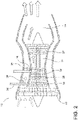
FIG. 3 is a schematic view of the aircraft gas turbine engine bleed air system in accordance with various aspects described herein. -
FIG. 4 is an example a flow chart diagram of demonstrating a method of providing bleed air to the environmental control system in accordance with various aspects described herein. -
FIG. 1 illustrates an embodiment of the disclosure, showing anaircraft 10 that can include ableed air system 20, only a portion of which has been illustrated for clarity purposes. As illustrated, theaircraft 10 can includemultiple engines 12, such asgas turbine engines 12, afuselage 14, acockpit 16 positioned in thefuselage 14, andwing assemblies 18 extending outward from thefuselage 14. The aircraft can also include an environmental control system (ECS) 48. The ECS 48 is schematically illustrated in thefuselage 14 of theaircraft 10 and is fluidly coupled with thebleed air system 20 to receive a supply of bleed air from theengines 12. - The
bleed air system 20 is connected to each of theengines 12 such that high temperature, high pressure air, or a combination thereof received from theengines 12 is used within theaircraft 10 for environmental control of theaircraft 10. More specifically, an engine can include a set ofbleed ports 24 arranged along thegas turbine engine 12 length or operational stages such that bleed air can be received, captured, or removed from thegas turbine engine 12 as the corresponding set ofbleed ports 24. In this sense, various bleed air characteristics, including but not limited to, bleed air mass flow rate (for example, in pounds per minute), bleed air temperature or bleed air pressure, can selected based on the desired operation or bleed air demand of thebleed air system 20. As used herein, the environmental control of theaircraft 10, that is, the ECS 48 of theaircraft 10, can include subsystems for anti-icing or de-icing a portion of the aircraft, for pressurizing the cabin or fuselage, heating or cooling the cabin or fuselage, and the like. The operation of the ECS 48 can be a function of at least one of the number ofaircraft 10 passengers,aircraft 10 flight phase, or operational subsystems of the ECS 48. Examples of theaircraft 10 flight phase can include, but is not limited to ground idle, taxi, takeoff, climb, cruise, descent, hold, and landing. The demand of thebleed air system 20 by the ECS can be dynamic as, for example, subsystems are needed based onaircraft 10 conditions. - While a
commercial aircraft 10 has been illustrated, it is contemplated that embodiments of the invention can be used in any type ofaircraft 10. Further, while twoengines 12 have been illustrated on eachwing assembly 18, it will be understood that any number ofengines 12 including a singlegas turbine engine 12 on eachwing assembly 18, or even a single gas turbine engine mounted in thefuselage 14 can be included. -
FIG. 2 illustrates a cross section of thegas turbine engine 12 of theaircraft 10. Thegas turbine engine 12 can include, in a serial relationship, afan 22, acompressor section 26, acombustion section 25, aturbine section 27, and anexhaust section 29. Thecompressor section 26 can include, in a serial relationship, a multi-stagelow pressure compressor 30 and a multi-stagehigh pressure compressor 32. - The
gas turbine engine 12 is also shown including a low pressure bleedport 34 arranged to pull, draw, or receive low pressure bleed air from thelow pressure compressor 30 and a high pressure bleedport 36 arranged to pull, draw, or receive high pressure bleed air from thehigh pressure compressor 32. Thebleed ports various sensors 28. By way of non-limiting example, thesensors 28 can include respective temperature sensors, respective flow rate sensors, or respective pressure sensors. While only a single low pressure bleedport 34 is illustrated, thelow pressure compressor 30 can include a set of low pressure bleedports 34 arranged at multiple stages of thecompressor 30 to pull, draw, or receive various bleed air characteristics, including but not limited to, bleed air mass flow rate, bleed air temperature, or bleed air pressure. Similarly, while only a single high pressure bleedport 36 is illustrated, thehigh pressure compressor 32 can include a set of high pressure bleedports 36 to pull, draw, or receive various bleed air characteristics, including but not limited to, bleed air mass flow rate, bleed air temperature, or bleed air pressure. Non-limiting examples, not defined in the claims, can further include configurations wherein at least one of the low or high pressure bleedport ports - During
gas turbine engine 12 operation, the rotation of thefan 22 draws in air, such that at least a portion of the air is supplied to thecompressor section 26. The air is pressurized to a low pressure by thelow pressure compressor 30, and then is further pressurized to a high pressure by thehigh pressure compressor 32. At this point in the engine operation, the low pressure bleedport 34 and the high pressure bleedport 36 draw, respectively low pressure air from thelow pressure compressor 30 and high pressure air from thehigh pressure compressor 32 and supply the air to theECS 48. High pressure air not drawn by the high pressure bleedport 36 is delivered to thecombustion section 25, wherein the high pressure air is mixed with fuel and combusted. The combusted gases are delivered downstream to theturbine section 27, which are rotated by the gases passing through theturbine section 27. The rotation of theturbine section 27, in turn, rotates thefan 22 and thecompressor section 26 upstream of theturbine section 27. Finally, the combusted gases are exhausted from thegas turbine engine 12 through theexhaust section 29. -
FIG. 3 illustrates a schematic view of thebleed air system 20 of theaircraft 10. As shown, thebleed air system 20 includes a turboair cycle machine 38 fluidly coupled upstream with the set of gas turbine engines (shown only as a single gas turbine engine 12) and fluidly coupled downstream with theECS 48. The turboair cycle machine 38 includes aturbine 40 and acompressor 42, such as a turbo compressor, rotatably coupled on a common shaft with theturbine 40. Thebleed air system 20 of the turboair cycle machine 38 includes a flow mixer or turbo-ejector 44 located downstream from themachine 38. - The low pressure and high pressure bleed
ports air cycle machine 38 by way of a proportional mixing orcontrollable valve assembly 45. In one aspect, the mixing orcontrollable valve assembly 45 can be arranged to supply the low pressure and high pressure bleed air to the turboair cycle machine 38. Non-limiting examples of the mixing orcontrollable valve assembly 45 can include a turbo-ejector proportional assembly, wherein the high pressure bleedport 36 entrains at least a portion of the low pressure bleed air of the low pressure bleedport 34, or "pulls" air from the low pressure bleedport 34, and provides the mixed, combined, or entrained air to the turboair cycle machine 38. Stated another way, the turbo-ejector proportional assembly can simultaneously supply at least a portion of the low pressure bleed air to thecompressor section 42 and entrain another portion of the low pressure bleed air with the high pressure bleed air. Embodiments of the disclosure can supply any ratio of low pressure bleed air to high pressure bleed air, such as up to 100% of a first bleed air, and 0% of the other bleed air. In another example embodiment of the disclosure, the supply ratio of the low pressure bleed air and high pressure bleed air can be selected to never go below, or alternatively, to never exceed, a predetermined ratio. For example, the low pressure bleedport 34 of thegas turbine engine 12 can be fluidly coupled with thecompressor 42 of the turboair cycle machine 38 by way of a firstcontrollable valve 46. Additionally, the high pressure bleedport 36 of thegas turbine engine 12 can be directly fluidly coupled with theturbine 40 of the turboair cycle machine 38 by way of a secondcontrollable valve 50. Non-limiting examples of the first or secondcontrollable valves gas turbine engine 12. For example, the rotational speed of thegas turbine engine 12 can include predetermined speed ranges or speed steps. - The low pressure bleed air provided by the low pressure bleed
port 34 can be further provided to theturbine 40, downstream of the respective first andsecond valves turbine 40 includes turbo ejector proportional assembly or a check valve 52 biased in the direction from the low pressure bleedport 34 toward the high pressure bleedport 36 or theturbine 40 of the turboair cycle machine 38. In this sense, the turbo ejector proportional assembly or the check valve 52 is configured such that fluid can only flow from the low pressure bleedport 34 to the high pressure bleedport 36 or theturbine 40 of the turboair cycle machine 38. - In accordance with the invention, the check valve 52 is selected or configured to provide fluid traversal from the low pressure bleed
port 34 toward the high pressure bleedport 36 under defined or respective pressures of the flow in the respective the low pressure bleedport 34 toward the high pressure bleedport 36. For example, the check valve 52 can be selected or configured to only provide fluid traversal, as shown, when the air pressure of the high pressure bleedport 36 is lower or less than the air pressure of the low pressure bleedport 34. In another example, the check valve 52 can be selected or configured such that the valve 52 closes, or self-actuates to a closed position under back pressure, that is when the pressure of the high pressure bleedport 36 is higher or greater than the air pressure of the low pressure bleedport 36. In accordance withclaims pressure bleed port 34 toward the highpressure bleed port 36. - The
compressor 42 of the turboair cycle machine 38 can include acompressor output 54, and theturbine 40 can include a turbine output 56. Thecompressor output 54 and the turbine output 56 are fluidly combined downstream of the turboair cycle machine 38. The flow mixer is arranged to fluidly combine thecompressor output 54 and the turbine output 56 to a common mixed flow that is supplied to thebleed air inlet 49 of theECS 48. In this sense, thebleed air system 20 preconditions the bleed air before the bleed air is received by thebleed air inlet 49 of theECS 48. - In the illustrated embodiment of the flow mixer, the turbo-ejector 44 pressurizes the turbine output 56 as it traverses a
narrow portion 58, or "throat" of the turbo-ejector 44, and fluidly injects thecompressor output 54 into thenarrow portion 58 of the turbo-ejector 44. The injection of thecompressor output 54 into the pressurized turbine output 56 at thenarrow portion 58 of the turbo-ejector 44 fluidly combines therespective outputs 54, 56. The turbo-ejector 44 or combinedoutputs 54, 56 are fluidly coupled downstream with theECS 48 at ableed air inlet 49. Embodiments of the disclosure can be included wherein thecompressor output 54, the turbine output 56, or the turbo-ejector 44 (e.g. downstream from the narrow portion 58) can include a set ofsensors 28. - The turbo-ejector 44, sometimes referred to as an "ejector pump" or an "ejector valve," works by injecting air from a higher pressure source into a nozzle at the input end of a venturi restriction, into which a lower pressure air source is also fed. Air from the higher pressure source is emitted downstream into the lower pressure flow at high velocity. Friction caused by the adjacency of the airstreams causes the lower pressure air to be accelerated ("entrained") and drawn through the venturi restriction. As the higher pressure air ejected into the lower pressure airstream expands toward the lower pressure of the low pressure air source, the velocity increases, further accelerating the flow of the combined or mixed airflow. As the lower pressure air flow is accelerated by its entrainment by the higher pressure source, the temperature and pressure of the low pressure source are reduced, resulting in more energy to be extracted or "recovered" from the turbine output. Non-limiting embodiments of the disclosure can be included wherein the high pressure air source is at a higher or greater temperature than the low pressure air source. However, in alternative embodiments of the disclosure, the entrainment and mixing process can occur without the high pressure air source having a higher or greater temperature than the low pressure air source. The above-described embodiments are application to the turbo-ejector 44 illustrated downstream of the turbo
air cycle machine 38, as well as to the turbo-ejector embodiment of the proportional mixingassembly 45. - The
aircraft 10 or bleedair system 20 can also include acontroller module 60 having aprocessor 62 andmemory 64. Thecontroller module 60 orprocessor 62 can be operably or communicatively coupled to thebleed air system 20, including itssensors 28, thefirst valve 46, thesecond valve 50, and theECS 48. Thecontroller module 60 orprocessor 62 can further be operably or communicatively coupled with thesensors 28 dispersed along the fluid couplings of thebleed air system 20. Thememory 64 can include random access memory (RAM), read-only memory (ROM), flash memory, or one or more different types of portable electronic memory, such as discs, DVDs, CD-ROMs, etc., or any suitable combination of these types of memory. Thecontroller module 60 orprocessor 62 can further be configured to run any suitable programs. Non-limiting embodiments of the disclosure can be included wherein, for example, thecontroller module 60 orprocessor 62 can also be connected with other controllers, processors, or systems of theaircraft 10, or can be included as part of or a subcomponent of another controller, processor, or system of theaircraft 10. - A computer searchable database of information can be stored in the
memory 64 and accessible by thecontroller module 60 orprocessor 62. Thecontroller module 60 orprocessor 62 can run a set of executable instructions to display the database or access the database. Alternatively, thecontroller module 60 orprocessor 62 can be operably coupled to a database of information. For example, such a database can be stored on an alternative computer or controller. It will be understood that the database can be any suitable database, including a single database having multiple sets of data, multiple discrete databases linked together, or even a simple table of data. It is contemplated that the database can incorporate a number of databases or that the database can actually be a number of separate databases. The database can store data that can include, among other things, historical data related to the reference value for the sensor outputs, as well as historicalbleed air system 20 data for theaircraft 10 and related to a fleet of aircraft. The database can also include reference values including historic values or aggregated values. - During
gas turbine engine 12 operation, thebleed air system 20 supplies a low pressure bleed airflow 66 along the lowpressure bleed port 34 and a highpressure bleed airflow 68 along the highpressure bleed port 36, as previously explained. The highpressure bleed airflow 68 is delivered to theturbine 40 of the turboair cycle machine 38, which in turn interacts with the turbine to drive the rotation of theturbine 40. The highpressure bleed airflow 68 exits theturbine section 40 at the turbine output 56 as aturbine output airflow 70. A first portion of the low pressure bleed airflow 66 can be delivered to thecompressor 42 of the turboair cycle machine 38, and a second portion of the low pressure bleed airflow 66 can be delivered to theturbine 40 of themachine 38, depending on the operation of the check valve 52 or turbo-ejector proportional assembly, or therespective airflows 66, 68 of the respective lowpressure bleed port 34 and highpressure bleed port 36, as explained herein. For example, embodiments of the disclosure can include operations wherein the airflow delivered to theturbine 40 can include entirely low pressure bleed airflow 66, no low pressure bleed airflow 66, or a portion therebetween. The second portion of the low pressure bleed airflow 66 can also be utilize to drive the rotation of theturbine 40. - The first portion of the low pressure bleed airflow 66 can be compressed by the rotation of the
compressor 42, which is rotatably coupled with theturbine 40. The compressed low pressure bleed airflow 66 exits thecompressor 42 at thecompressor output 54 as acompressor output airflow 72. Theturbine output airflow 70 and thecompressor output airflow 72 are combined in the turbo-ejector 44 to form a combinedairflow stream 74, which is further provided to theECS 48. In this sense, the combinedairflow stream 74 can be expressed as a composition or a ratio of the low pressure and highpressure bleed airflow 66, 68, or a composition of a ratio of the turbine andcompressor output airflows - The compression of the low pressure airflow 66, by the
compressor 42, generates a higher pressure and higher temperaturecompressor output airflow 72, compared with the low pressure airflow 66. Additionally, the airflows received by theturbine 40, that is, thehigh pressure airflow 68 and selective low pressure airflow 66 via the check valve 52 or turbo-ejector proportional assembly, generates a lower pressure and a lower temperatureturbine output airflow 70, compared with theturbine 40input airflows 66, 68. In this sense, thecompressor 42 outputs or emits a hotter andhigher pressure airflow 72, while theturbine 40 outputs or emits a cooler andlower pressure airflow 70, compared with therelative input airflows 66, 68. - The
controller module 60 orprocessor 62 can be configured to operably receive a bleed air demand, generated by, for example, theECS 48. The bleed air demand can be provided to thecontroller module 60 orprocessor 62 by way of a bleedair demand signal 76, which can include bleed air demand characteristics included, but not limited to, flow rate, temperature, or pressure. In response to the bleedair demand signal 76, thecontroller module 60 orprocessor 62 can operably supply proportional amounts of the low pressure bleed airflow 66 and highpressure bleed airflow 68 to the turboair cycle machine 38. The proportionality of the low pressure and highpressure bleed airflows 66, 68 can be controlled by way of the respective first or secondcontrollable valves - The proportional supplying of the low pressure and high
pressure bleed airflows 66, 68 can be directly or geometrically proportional to theturbine output airflow 70 andcompressor output airflow 72, or the turbineair cycle machine 38 operations. Theturbine output airflow 70 andcompressor output airflow 72 are combined downstream of the turboair cycle machine 38, and the combinedairflow stream 74 is provided to theECS 48. In one non-limiting example, thecompressor output airflow 72 can drive theturbine output airflow 70 into thenarrow portion 58 and mix under sonic conditions. The mixed flow pressure will recover statically through the combinedairflow stream 74 to output the turbo-ejector 44 at desired conditions. In this sense, the combinedairflow stream 74 is conditioned by way of operation of thebleed air system 20,controllable valves air cycle machine 3 8, the combining of theturbine output airflow 70 and thecompressor output airflow 72, or any combination thereof, to meet theECS 48 demand for bleed air. - One of the
controller module 60 orprocessor 62 can include all or a portion of a computer program having an executable instruction set for determining the bleed air demand of theECS 48, proportionally supplying the low pressure or highpressure bleed airflows 66, 68, operating thecontrollable valves low pressure airflows 66, 68, or a combination thereof. Regardless of whether thecontroller module 60 orprocessor 62 controls the operation of thebleed air system 20, the program can include a computer program product that can include machine-readable media for carrying or having machine-executable instructions or data structures stored thereon. Such machine-readable media can be any available media, which can be accessed by a general purpose or special purpose computer or other machine with a processor. Generally, such a computer program can include routines, programs, objects, components, data structures, and the like, that have the technical effect of performing particular tasks or implementing particular abstract data types. Machine-executable instructions, associated data structures, and programs represent examples of program code for executing the exchange of information as disclosed herein. Machine-executable instructions can include, for example, instructions and data, which cause a general-purpose computer, special purpose computer, or special purpose processing machine to perform a certain function or group of functions. - While the bleed air characteristics of the low pressure or high
pressure bleed airflows 66, 68 can remain relatively consistent or stable during a cruise portion of a flight by theaircraft 10, varyingaircraft 10 or flight characteristics, such as altitude, speed, heading, solar cycle, or geographic aircraft location can produceinconsistent airflows 66, 68 in thebleed air system 20. Thus, thecontroller module 60 orprocessor 62 can also be configured to operate thebleed air system 20, as explained herein, in response to receiving a set of sensor input values received by thesensors 28 dispersed along the fluid couplings of thebleed air system 20. For example, thecontroller module 60 orprocessor 62 can include predetermined, known, expected, estimated, or calculated values for the set ofairflows bleed air system 20. In response to varyingaircraft 10 or flight characteristics, thecontroller module 60 orprocessor 62 can alter the proportional supplying of the low pressure or highpressure bleed airflows 66, 68 in order to meet the bleed air demand for theECS 48. Alternatively, thememory 64 can include a database or lookup table such that a proportional supplying values related to the low pressure or highpressure bleed airflows 66, 68 can be determined in response to thecontroller module 60 receiving a set or subset ofsensor 28 readings, measurements, or the like. - While
sensors 28 are described as "sensing," "measuring," or "reading" respective temperatures, flow rates, or pressures, thecontroller module 60 orprocessor 62 can be configured to sense, measure, estimate, calculate, determine, or monitor thesensor 28 outputs, such that thecontroller module 60 orprocessor 62 interprets a value representative or indicative of the respective temperature, flow rate, pressure, or combination thereof. Additionally,sensors 28 can be included proximate to, or integral with additional components not previously demonstrated. For example, embodiments of the disclosure can includesensors 28 located to sense the combinedairflow stream 74, or can includesensors 28 located within thenarrow portion 58, or "throat" of the turbo-ejector 44. - In one non-limiting example of responsive operation, if the high
pressure bleed airflow 68 received by the highpressure bleed port 36 includes a higher than expected pressure, or a higher than expected temperature, as sensed by asensor 28, thecontroller module 60 orprocessor 62 can operate thebleed air system 20 to partially close thesecond valve 50. In another non-limiting example of responsive operation, if the low pressure bleed airflow 66 received by the lowpressure bleed port 34 includes a lower than expected pressure, or a lower than expected temperature, as sensed by asensor 28, thecontroller module 60 orprocessor 62 can operate thebleed air system 20 partially open thesecond valve 50, which increases the highpressure bleed airflow 68. The increase in highpressure bleed airflow 68, in turn, increases the rotation of theturbine 40, increasing the compression of thecompressor 42. The increase in compression of thecompressor 42 raises the pressure and temperature of thecompressor output airflow 70. - Embodiments of the disclosure can be included wherein the
controller module 60 orprocessor 62 can be configured to operate thebleed air system 20 to account forsensor 28 measurements in the set or a subset of theairflows - In another embodiment of the disclosure, the
bleed air system 20 can operate without feedback inputs, that is, without thecontroller module 60 orprocessor 62 receiving sensed information from thesensors 28. In this alternative configuration, thecontroller module 60 orprocessor 62 can be configured to operate the first orsecond valves aircraft 10, such as theaircraft 10 flight phases. - In one non-limiting example configuration of the
bleed air system 20, wherein the ambient air outside of theaircraft 10 orgas turbine engine 12 has an air pressure of 0,188 bar ( 2.72 pounds per square inch, absolute (psiA)) and a temperature of -56,5°C ( -69.7 degrees Fahrenheit (F)), the low pressure bleed airflow can include a pressure of 1,232 bar (17.87 psi, gage (psiG)) and a temperature of 141,7°C (287.09 degrees F), while high pressure bleed airflow can include a pressure of 3,953 bar (57.34 psiG) and a temperature of 325,8°C (618.44 degrees F). In this example, a ratio of low pressure bleed airflow 66 to highpressure bleed airflow 68 can be 53.77% to 46.23%. This ratio can operate the turboair cycle machine 38 to produce aturbine output airflow 70 having a pressure of 2,407 bar ( 34.91 psiG) and a temperature of 83,5°C (182.35 degrees F), while thecompressor output airflow 72 can include a pressure of 4,682 bar (67.9 psiG) and a temperature of 361,4°C( 682.59 degrees). The turbo-ejector 44 can be configured to combine theturbine output airflow 70 and thecompressor output airflow 72 to provide a combinedairflow stream 74 including a pressure of 3,304 bar (47.92 psiG) and a temperature of 234,6 °C(454.27 degrees F). The aforementioned example configuration and values are merely one non-limiting example of thebleed air system 20 described herein. -
FIG. 4 illustrates a flow chart demonstrating anon-limiting example method 100 of providing bleed air to theECS 48 of anaircraft 10 using a gas turbinegas turbine engine 12. Themethod 100 begins by determining a bleed air demand for theECS 110. The determining the bleed air demand for theECS 110 can include determining at least one of an air pressure, an air temperature, or a flow rate demand for theECS 48, or a combination thereof. The bleed air demand can be a function of at least one of the number ofaircraft 10 passengers,aircraft 10 flight phase, or operational subsystems of theECS 48. The bleed air demand can be determined by theECS 48, thecontroller module 60, or theprocessor 62, based on the bleedair demand signal 76. - Next, the
controller module 60 or theprocessor 62 operably controls the proportionalmixing valve assembly 45 to proportionally supply the low pressure and highpressure bleed air 120 such that turboair cycle machine 38 emits a cooled air stream from theturbine 40 and a compressed air stream from thecompressor 42. Embodiments of the disclosure can include, but are not limited to, supplying up to 100% of the combinedairflow stream 74 of one of the low pressure or highpressure bleed airflow pressure bleed airflow 66, 68. Another example embodiment of the disclosure can include, but is not limited to, step-wise proportionally supplying the low pressure and highpressure bleed airflows 66, 68, wherein the step-wise supplying is related to, or is a function of theaircraft 10 flight phase or rotational speed of thegas turbine engine 12. The proportionally supplying of thebleed air 120 can include continuously proportionally supplying thebleed air 120, that is, repeatedly altering the proportional supplying of the low pressure and highpressure bleed airflows 66, 68 over a period of time, or indefinitely during the flight of theaircraft 10. - The
method 100 continues by combining the cooled air stream and thecompressed air stream 130 to form a conditioned or combinedairflow stream 74. The proportional supplying the low pressure and the highpressure bleed air 120 is controlled by thecontroller module 60 orprocessor 62 such that the combinedairflow stream 74 meets the determined bleed air demand for the ECS. - The sequence depicted is for illustrative purposes only and is not meant to limit the
method 100 in any way as it is understood that the portions of the method can proceed in a different logical order, additional or intervening portions can be included, or described portions of the method can be divided into multiple portions, or described portions of the method can be omitted without detracting from the described method. - Many other possible embodiments and configurations in addition to that shown in the above figures are contemplated by the present disclosure. For example, embodiments of the disclosure can be included wherein the
second valve 50 could be replaced with a bleed ejector or mixing valve also coupled with the lowpressure bleed port 34. In another non-limiting example, the turbo-ejector 44, thecompressor output 54, or the turbine output 56 can be configured to prevent backflow from downstream components from entering the turboair cycle machine 38. In yet another non-limiting example embodiment of the disclosure, the check valve 52 or turbo-ejector proportional assembly can include, or can be replaced by a third controllable valve, and controlled by thecontroller module 60 as explained herein, to operate or effect a ratio of low pressure bleed airflow 66 and highpressure bleed airflow 68 supplied to theturbine 40. Additionally, the design and placement of the various components such as valves, pumps, or conduits can be rearranged such that a number of different in-line configurations could be realized. - The embodiments disclosed herein provide a method and aircraft for providing bleed air to an environmental control system. The technical effect is that the above described embodiments enable the preconditioning of bleed air received from a gas turbine engine such that the conditioning and combining of the bleed air is selected to meet a bleed air demand for the environmental control system. One advantage that can be realized in the above embodiments is that the above described embodiments have superior bleed air conditioning for the ECS without wasting excess heat, compared with traditional pre-cooler heat exchanger systems. Another advantage that can be realized is that by eliminating the waste of excess heat, the system can further reduce bleed extraction from the engine related to the wasted heat. By reducing bleed extraction, the engine operates with improved efficiency, yielding fuel cost savings and increasing operable flight range for the aircraft.
- Yet another advantage that can be realized by the above embodiments is that the bleed air system can provide variable bleed air conditioning for the ECS. The variable bleed air can meet a variable demand for bleed air in the ECS due to a variable ECS load, for example, as subsystems are operated or cease to operate.
- This written description uses examples to disclose embodiments of the invention, including the best mode, and also to enable any person skilled in the art to practice embodiments of the invention, including making and using any devices or systems and performing any incorporated methods. The patentable scope of the invention is defined by the claims, and can include other examples that occur to those skilled in the art. Such other examples are intended to be within the scope of the claims if they have structural elements that do not differ from the literal language of the claims.
Claims (14)
- A method of providing bleed air to environmental control systems (ECS) using a gas turbine engine (12), the gas turbine engine (12) providing a low pressure bleed air supply (34) and a high pressure bleed air supply (36), the method comprising:determining (110) a bleed air demand for the ECS (48);proportionally supplying low pressure and high pressure bleed air from a compressor of the gas turbine engine to a turbo air cycle machine, by supplying (120) low pressure bleed air from the low pressure bleed air supply (34) to a compressor section (42) of the turbo air cycle machine (38), and high pressure bleed air from the high pressure bleed air supply (36) to a turbine section (40) of the turbo air cycle machine (38);controlling, by a check valve (52) or turbo ejector, traversal of at least a portion of the low pressure bleed air from the low pressure bleed air supply (34) to the high pressure bleed air supply (36) under defined or respective pressures of the flows in the respective low pressure bleed air supply (34) and the high pressure bleed air supply (36);emitting a cooled air stream from the turbine section (40) and a compressed air stream from the compressor section (42); andcombining (130) the cooled air stream and the compressed air stream to form a conditioned air stream;wherein the proportional supplying is controlled such that the conditioned air stream meets the determined bleed air demand.
- The method of claim 1 wherein the determining (110) the bleed air demand comprises determining at least one of air pressure or air temperature demand for the ECS (48).
- The method of claim 2 wherein the determining (110) the bleed air demand comprises determining both the air pressure and the air temperature demand for the ECS (48).
- The method of claim 1 wherein the bleed air demand is a function of at least one of number of aircraft passengers, aircraft flight phase, or operational subsystems of the ECS (48).
- The method of claim 1 wherein proportionally supplying (120) low pressure and high pressure bleed air comprises supplying 100% of one of the low pressure or high pressure bleed air and 0% of the other of the low pressure and high pressure bleed air.
- The method of claim 1 wherein proportionally supplying low pressure and high pressure bleed air by controlling traversal of at least a portion of the low pressure bleed air from the low pressure bleed air supply (34) to the high pressure bleed air supply (36) comprises step-wise controlling the traversal.
- The method of claim 6 wherein the step-wise controlling is a function of the aircraft flight phase.
- The method of claim 7 wherein the aircraft flight phase is one of ground idle, taxi, takeoff, climb, cruise, descent, hold, and landing.
- The method of claim 6 wherein the step-wise controlling is a function of the rotational speed of the gas turbine engine (12).
- The method of claim 6 wherein the rotational speed of the gas turbine engine (12) comprises predetermined speed ranges for the gas turbine engine (12).
- The method of claim 1 wherein proportionally supplying low pressure and high pressure bleed air by controlling the traversal comprises continuously controlling the traversal.
- An aircraft (10) comprising:an environmental control system (ECS) (48) having a bleed air inlet (49);a gas turbine engine (12) having a low pressure bleed air supply (34) and a high pressure bleed air supply (36);a turbo air cycle machine (38) having rotationally coupled turbine and compressor sections (40, 42);characterized in the aircraft further comprisesa turbo-ejector or a check-valve (52) fluidly coupling the low and high pressure bleed air supplies (34, 36) upstream of the air cycle machine, the turbo-ejector or check valve (52) being configured or controlled to provide fluid traversal from the low pressure bleed air supply (34) toward the high pressure bleed air supply (36) under defined or respective pressures of the respective flows in the low pressure bleed air supply (34) and the high pressure bleed air supply (36); anda downstream turbo-ejector (44) fluidly combining fluid outputs from the turbine and compressor sections into a common flow that is supplied to the bleed air inlet (49) of the ECS (48).
- The aircraft of claim 12 wherein the environmental control system (48) comprises an air-conditioning subsystem and a de-icing subsystem.
- The aircraft of claim 12 wherein the upstream turbo-ejector comprises directly fluidly coupling the high pressure bleed air supply (36) with the turbine section (40).
Applications Claiming Priority (2)
| Application Number | Priority Date | Filing Date | Title |
|---|---|---|---|
| US15/043,517 US20170233081A1 (en) | 2016-02-13 | 2016-02-13 | Method and aircraft for providing bleed air to an environmental control system |
| PCT/US2017/017600 WO2017139729A1 (en) | 2016-02-13 | 2017-02-13 | Method and aircraft providing bleed air to an environmental control system |
Publications (2)
| Publication Number | Publication Date |
|---|---|
| EP3414162A1 EP3414162A1 (en) | 2018-12-19 |
| EP3414162B1 true EP3414162B1 (en) | 2022-04-27 |
Family
ID=58213330
Family Applications (1)
| Application Number | Title | Priority Date | Filing Date |
|---|---|---|---|
| EP17708612.1A Active EP3414162B1 (en) | 2016-02-13 | 2017-02-13 | Method and aircraft providing bleed air to an environmental control system |
Country Status (4)
| Country | Link |
|---|---|
| US (2) | US20170233081A1 (en) |
| EP (1) | EP3414162B1 (en) |
| CN (1) | CN108698702B (en) |
| WO (1) | WO2017139729A1 (en) |
Families Citing this family (23)
| Publication number | Priority date | Publication date | Assignee | Title |
|---|---|---|---|---|
| US10464668B2 (en) | 2015-09-02 | 2019-11-05 | Jetoptera, Inc. | Configuration for vertical take-off and landing system for aerial vehicles |
| US11001378B2 (en) | 2016-08-08 | 2021-05-11 | Jetoptera, Inc. | Configuration for vertical take-off and landing system for aerial vehicles |
| EP4306789A3 (en) | 2015-09-02 | 2024-06-12 | Jetoptera, Inc. | Fluidic propulsive system |
| US20170067578A1 (en) * | 2015-09-09 | 2017-03-09 | Honeywell International Inc. | Detection of high stage valve leakage by pressure lockup |
| US11377216B2 (en) | 2016-08-23 | 2022-07-05 | Ge Aviation Systems Llc | Advanced method and aircraft for pre-cooling an environmental control system using a dual compressor four wheel turbo-machine |
| US11459906B2 (en) * | 2017-05-22 | 2022-10-04 | Raytheon Technologies Corporation | Actively-driven bleed source switching |
| IL307470A (en) | 2017-06-27 | 2023-12-01 | Jetoptera Inc | Configuration for vertical take-off and landing system for aerial vehicles |
| US11180259B2 (en) * | 2018-03-21 | 2021-11-23 | Hamilton Sundstrand Corporation | Synthesized low-pressure bleed air scheme for aircraft bleed air network |
| US11078841B2 (en) * | 2018-04-09 | 2021-08-03 | The Boeing Company | Bleed air systems for use with aircraft and related methods |
| US10745139B2 (en) * | 2018-06-27 | 2020-08-18 | Hamilton Sundstrand Corporation | Simultaneous dual engine bleed thermal management system |
| DE102018211907B4 (en) * | 2018-07-17 | 2025-02-13 | Rolls-Royce Deutschland Ltd & Co Kg | air supply system for an aircraft |
| US11008948B2 (en) | 2018-09-13 | 2021-05-18 | Hamilton Sundstrand Corporation | Adaptable dual delta-P flow measurement |
| ES2947461T3 (en) * | 2019-07-01 | 2023-08-09 | Airbus Operations Slu | Aircraft installation for pressurized air supply |
| ES2953700T3 (en) * | 2019-07-01 | 2023-11-15 | Airbus Operations Slu | Air management system |
| FR3101613B1 (en) * | 2019-10-07 | 2021-09-24 | Liebherr Aerospace Toulouse Sas | PROTECTION DEVICE FOR AN ELEMENT OF AN AIR CONDITIONING SYSTEM AGAINST CONTACT WITH AN ADVERSE OBJECT |
| EP3835207B1 (en) * | 2019-12-10 | 2023-08-23 | Collins Aerospace Ireland, Limited | Aircraft environmental control system |
| CN112177778A (en) * | 2020-08-28 | 2021-01-05 | 成都飞机工业(集团)有限责任公司 | Temperature and pressure regulating method for bleed air of engine |
| US11486315B2 (en) | 2020-11-06 | 2022-11-01 | Ge Aviation Systems Llc | Combustion engine including turbomachine |
| FR3117455B1 (en) * | 2020-12-11 | 2023-04-14 | Liebherr Aerospace Toulouse Sas | AIRCRAFT DISTRIBUTED PNEUMATIC POWER SYSTEM |
| US11441963B1 (en) * | 2021-05-03 | 2022-09-13 | Rosemount Aerospace Inc. | Aircraft pressure measurement device including an enhanced cleaning system |
| US12320825B2 (en) | 2022-08-11 | 2025-06-03 | Rosemount Aerospace Inc. | Probe blockage detection and removal |
| US12078103B1 (en) * | 2023-08-04 | 2024-09-03 | Rolls-Royce North American Technologies Inc. | Anti-ice mixing unit utilizing bleed air for a gas turbine engine |
| US12276229B2 (en) * | 2023-09-08 | 2025-04-15 | General Electric Company | Method of operating a turbine engine having a bleed system |
Family Cites Families (27)
| Publication number | Priority date | Publication date | Assignee | Title |
|---|---|---|---|---|
| US3441045A (en) * | 1966-12-02 | 1969-04-29 | Boeing Co | Variable orifice nozzle mixing ejector |
| US3842720A (en) * | 1973-03-29 | 1974-10-22 | Piper Aircraft Corp | Jet pump for aircraft cabin pressurization system |
| US5114103A (en) * | 1990-08-27 | 1992-05-19 | General Electric Company | Aircraft engine electrically powered boundary layer bleed system |
| US5899085A (en) | 1997-08-01 | 1999-05-04 | Mcdonnell Douglas Corporation | Integrated air conditioning and power unit |
| US6412270B1 (en) * | 2001-09-12 | 2002-07-02 | General Electric Company | Apparatus and methods for flowing a cooling or purge medium in a turbine downstream of a turbine seal |
| US7861536B2 (en) * | 2006-03-27 | 2011-01-04 | Pratt & Whitney Canada Corp. | Ejector controlled twin air source gas turbine pressurizing air system |
| DE102006042584B4 (en) * | 2006-09-11 | 2008-11-20 | Airbus Deutschland Gmbh | Air supply system of an aircraft and method for mixing two air streams in an air supply system |
| KR101212433B1 (en) | 2007-03-12 | 2012-12-13 | 가부시키가이샤 구라레 | Method for production of porous ceramic material |
| US8019522B2 (en) * | 2008-09-30 | 2011-09-13 | General Electric Company | Method and system for providing cooling and power |
| US8142169B2 (en) * | 2009-01-06 | 2012-03-27 | General Electric Company | Variable geometry ejector |
| US20110162386A1 (en) * | 2010-01-04 | 2011-07-07 | Shinoj Vakkayil Chandrabose | Ejector-OBB Scheme for a Gas Turbine |
| US9062604B2 (en) * | 2011-01-14 | 2015-06-23 | Hamilton Sundstrand Corporation | Low pressure bleed architecture |
| US9222410B2 (en) * | 2011-04-13 | 2015-12-29 | General Electric Company | Power plant |
| GB2499577A (en) * | 2011-11-29 | 2013-08-28 | Eaton Aerospace Ltd | Aircraft on board inert gas generation system |
| US8904805B2 (en) * | 2012-01-09 | 2014-12-09 | United Technologies Corporation | Environmental control system for aircraft utilizing turbo-compressor |
| US8967528B2 (en) * | 2012-01-24 | 2015-03-03 | The Boeing Company | Bleed air systems for use with aircrafts and related methods |
| US8955794B2 (en) * | 2012-01-24 | 2015-02-17 | The Boeing Company | Bleed air systems for use with aircrafts and related methods |
| US20130232941A1 (en) * | 2012-03-07 | 2013-09-12 | Ge Aviation Systems Llc | Apparatus for extracting input power from the low pressure spool of a turbine engine |
| CN102874410B (en) * | 2012-09-14 | 2015-01-07 | 北京航空航天大学 | High-speed motor driven air circulating refrigeration system |
| EP2829706B1 (en) * | 2013-07-25 | 2016-09-14 | The Boeing Company | Bleed air systems for use with aircrafts and related methods |
| US10830133B2 (en) * | 2013-09-03 | 2020-11-10 | Hamilton Sundstrand Corporation | Aircraft environmental control system selectively powered by three bleed ports |
| US20150065023A1 (en) | 2013-09-03 | 2015-03-05 | Hamilton Sundstrand Corporation | Intercompressor bleed turbo compressor |
| US9382841B2 (en) * | 2013-09-03 | 2016-07-05 | Hamilton Sundstrand Corporation | Aircraft environmental control system selectively powered by three bleed ports |
| US9580180B2 (en) * | 2014-03-07 | 2017-02-28 | Honeywell International Inc. | Low-pressure bleed air aircraft environmental control system |
| CN106460677B (en) * | 2014-05-21 | 2018-09-18 | 西门子能源公司 | Method of providing cooling flow from a compressor to a turbine in a gas turbine |
| EP3372802B1 (en) * | 2014-07-07 | 2023-10-25 | Raytheon Technologies Corporation | Low pressure environmental control system with safe pylon transit |
| US20160177820A1 (en) * | 2014-07-07 | 2016-06-23 | United Technologies Corporation | Low pressure environmental control system with safe pylon transit |
-
2016
- 2016-02-13 US US15/043,517 patent/US20170233081A1/en not_active Abandoned
-
2017
- 2017-02-13 CN CN201780011161.2A patent/CN108698702B/en active Active
- 2017-02-13 EP EP17708612.1A patent/EP3414162B1/en active Active
- 2017-02-13 WO PCT/US2017/017600 patent/WO2017139729A1/en not_active Ceased
-
2020
- 2020-06-30 US US16/917,213 patent/US11305878B2/en active Active
Also Published As
| Publication number | Publication date |
|---|---|
| CN108698702A (en) | 2018-10-23 |
| US20170233081A1 (en) | 2017-08-17 |
| CN108698702B (en) | 2022-06-24 |
| US11305878B2 (en) | 2022-04-19 |
| US20200331615A1 (en) | 2020-10-22 |
| EP3414162A1 (en) | 2018-12-19 |
| WO2017139729A1 (en) | 2017-08-17 |
Similar Documents
| Publication | Publication Date | Title |
|---|---|---|
| US11305878B2 (en) | Aircraft with environmental control system | |
| US20180057170A1 (en) | Enhanced method and aircraft for pre-cooling an environmental control system using a two wheel turbo-machine with supplemental heat exchanger | |
| US20220297841A1 (en) | Aircraft and method for pre-cooling an environmental control system | |
| US20180057171A1 (en) | Advanced method and aircraft for pre-cooling an environmental control system using a three wheel turbo-machine | |
| EP3287370B1 (en) | Hybrid method and aircraft for pre-cooling an environmental control system using a power generator four wheel turbo-machine | |
| US10634065B2 (en) | Engine bleed air system | |
| EP3907388B1 (en) | Engine bleed power recovery systems and related methods | |
| US9239005B2 (en) | Cooling system for engine and aircraft air | |
| EP2620616B1 (en) | Bleed air systems for use with aircrafts and related methods | |
| US8899008B2 (en) | System and method for heat recovery in a gas turbine engine | |
| US10563581B2 (en) | System and method of compressor inlet temperature control with eductor | |
| US10619568B2 (en) | System and method of compressor inlet temperature control with mixing chamber | |
| US20170342900A1 (en) | System and method of compressor inlet temperature control with eductor | |
| US20170342902A1 (en) | System and method of compressor inlet temperature control | |
| US20120256045A1 (en) | Airborne cooling system |
Legal Events
| Date | Code | Title | Description |
|---|---|---|---|
| STAA | Information on the status of an ep patent application or granted ep patent |
Free format text: STATUS: UNKNOWN |
|
| STAA | Information on the status of an ep patent application or granted ep patent |
Free format text: STATUS: THE INTERNATIONAL PUBLICATION HAS BEEN MADE |
|
| PUAI | Public reference made under article 153(3) epc to a published international application that has entered the european phase |
Free format text: ORIGINAL CODE: 0009012 |
|
| STAA | Information on the status of an ep patent application or granted ep patent |
Free format text: STATUS: REQUEST FOR EXAMINATION WAS MADE |
|
| 17P | Request for examination filed |
Effective date: 20180913 |
|
| AK | Designated contracting states |
Kind code of ref document: A1 Designated state(s): AL AT BE BG CH CY CZ DE DK EE ES FI FR GB GR HR HU IE IS IT LI LT LU LV MC MK MT NL NO PL PT RO RS SE SI SK SM TR |
|
| AX | Request for extension of the european patent |
Extension state: BA ME |
|
| DAV | Request for validation of the european patent (deleted) | ||
| DAX | Request for extension of the european patent (deleted) | ||
| STAA | Information on the status of an ep patent application or granted ep patent |
Free format text: STATUS: EXAMINATION IS IN PROGRESS |
|
| 17Q | First examination report despatched |
Effective date: 20200210 |
|
| GRAP | Despatch of communication of intention to grant a patent |
Free format text: ORIGINAL CODE: EPIDOSNIGR1 |
|
| STAA | Information on the status of an ep patent application or granted ep patent |
Free format text: STATUS: GRANT OF PATENT IS INTENDED |
|
| RIC1 | Information provided on ipc code assigned before grant |
Ipc: F02C 9/18 20060101ALI20211027BHEP Ipc: B64D 13/06 20060101ALI20211027BHEP Ipc: F02C 6/08 20060101ALI20211027BHEP Ipc: B64D 13/02 20060101AFI20211027BHEP |
|
| INTG | Intention to grant announced |
Effective date: 20211126 |
|
| GRAS | Grant fee paid |
Free format text: ORIGINAL CODE: EPIDOSNIGR3 |
|
| GRAA | (expected) grant |
Free format text: ORIGINAL CODE: 0009210 |
|
| STAA | Information on the status of an ep patent application or granted ep patent |
Free format text: STATUS: THE PATENT HAS BEEN GRANTED |
|
| AK | Designated contracting states |
Kind code of ref document: B1 Designated state(s): AL AT BE BG CH CY CZ DE DK EE ES FI FR GB GR HR HU IE IS IT LI LT LU LV MC MK MT NL NO PL PT RO RS SE SI SK SM TR |
|
| REG | Reference to a national code |
Ref country code: GB Ref legal event code: FG4D |
|
| REG | Reference to a national code |
Ref country code: CH Ref legal event code: EP |
|
| REG | Reference to a national code |
Ref country code: DE Ref legal event code: R096 Ref document number: 602017056508 Country of ref document: DE |
|
| REG | Reference to a national code |
Ref country code: AT Ref legal event code: REF Ref document number: 1486784 Country of ref document: AT Kind code of ref document: T Effective date: 20220515 |
|
| REG | Reference to a national code |
Ref country code: IE Ref legal event code: FG4D |
|
| REG | Reference to a national code |
Ref country code: LT Ref legal event code: MG9D |
|
| REG | Reference to a national code |
Ref country code: NL Ref legal event code: MP Effective date: 20220427 |
|
| REG | Reference to a national code |
Ref country code: AT Ref legal event code: MK05 Ref document number: 1486784 Country of ref document: AT Kind code of ref document: T Effective date: 20220427 |
|
| PG25 | Lapsed in a contracting state [announced via postgrant information from national office to epo] |
Ref country code: NL Free format text: LAPSE BECAUSE OF FAILURE TO SUBMIT A TRANSLATION OF THE DESCRIPTION OR TO PAY THE FEE WITHIN THE PRESCRIBED TIME-LIMIT Effective date: 20220427 |
|
| PG25 | Lapsed in a contracting state [announced via postgrant information from national office to epo] |
Ref country code: SE Free format text: LAPSE BECAUSE OF FAILURE TO SUBMIT A TRANSLATION OF THE DESCRIPTION OR TO PAY THE FEE WITHIN THE PRESCRIBED TIME-LIMIT Effective date: 20220427 Ref country code: PT Free format text: LAPSE BECAUSE OF FAILURE TO SUBMIT A TRANSLATION OF THE DESCRIPTION OR TO PAY THE FEE WITHIN THE PRESCRIBED TIME-LIMIT Effective date: 20220829 Ref country code: NO Free format text: LAPSE BECAUSE OF FAILURE TO SUBMIT A TRANSLATION OF THE DESCRIPTION OR TO PAY THE FEE WITHIN THE PRESCRIBED TIME-LIMIT Effective date: 20220727 Ref country code: LT Free format text: LAPSE BECAUSE OF FAILURE TO SUBMIT A TRANSLATION OF THE DESCRIPTION OR TO PAY THE FEE WITHIN THE PRESCRIBED TIME-LIMIT Effective date: 20220427 Ref country code: HR Free format text: LAPSE BECAUSE OF FAILURE TO SUBMIT A TRANSLATION OF THE DESCRIPTION OR TO PAY THE FEE WITHIN THE PRESCRIBED TIME-LIMIT Effective date: 20220427 Ref country code: GR Free format text: LAPSE BECAUSE OF FAILURE TO SUBMIT A TRANSLATION OF THE DESCRIPTION OR TO PAY THE FEE WITHIN THE PRESCRIBED TIME-LIMIT Effective date: 20220728 Ref country code: FI Free format text: LAPSE BECAUSE OF FAILURE TO SUBMIT A TRANSLATION OF THE DESCRIPTION OR TO PAY THE FEE WITHIN THE PRESCRIBED TIME-LIMIT Effective date: 20220427 Ref country code: ES Free format text: LAPSE BECAUSE OF FAILURE TO SUBMIT A TRANSLATION OF THE DESCRIPTION OR TO PAY THE FEE WITHIN THE PRESCRIBED TIME-LIMIT Effective date: 20220427 Ref country code: BG Free format text: LAPSE BECAUSE OF FAILURE TO SUBMIT A TRANSLATION OF THE DESCRIPTION OR TO PAY THE FEE WITHIN THE PRESCRIBED TIME-LIMIT Effective date: 20220727 Ref country code: AT Free format text: LAPSE BECAUSE OF FAILURE TO SUBMIT A TRANSLATION OF THE DESCRIPTION OR TO PAY THE FEE WITHIN THE PRESCRIBED TIME-LIMIT Effective date: 20220427 |
|
| PG25 | Lapsed in a contracting state [announced via postgrant information from national office to epo] |
Ref country code: RS Free format text: LAPSE BECAUSE OF FAILURE TO SUBMIT A TRANSLATION OF THE DESCRIPTION OR TO PAY THE FEE WITHIN THE PRESCRIBED TIME-LIMIT Effective date: 20220427 Ref country code: PL Free format text: LAPSE BECAUSE OF FAILURE TO SUBMIT A TRANSLATION OF THE DESCRIPTION OR TO PAY THE FEE WITHIN THE PRESCRIBED TIME-LIMIT Effective date: 20220427 Ref country code: LV Free format text: LAPSE BECAUSE OF FAILURE TO SUBMIT A TRANSLATION OF THE DESCRIPTION OR TO PAY THE FEE WITHIN THE PRESCRIBED TIME-LIMIT Effective date: 20220427 Ref country code: IS Free format text: LAPSE BECAUSE OF FAILURE TO SUBMIT A TRANSLATION OF THE DESCRIPTION OR TO PAY THE FEE WITHIN THE PRESCRIBED TIME-LIMIT Effective date: 20220827 |
|
| REG | Reference to a national code |
Ref country code: DE Ref legal event code: R097 Ref document number: 602017056508 Country of ref document: DE |
|
| PG25 | Lapsed in a contracting state [announced via postgrant information from national office to epo] |
Ref country code: SM Free format text: LAPSE BECAUSE OF FAILURE TO SUBMIT A TRANSLATION OF THE DESCRIPTION OR TO PAY THE FEE WITHIN THE PRESCRIBED TIME-LIMIT Effective date: 20220427 Ref country code: SK Free format text: LAPSE BECAUSE OF FAILURE TO SUBMIT A TRANSLATION OF THE DESCRIPTION OR TO PAY THE FEE WITHIN THE PRESCRIBED TIME-LIMIT Effective date: 20220427 Ref country code: RO Free format text: LAPSE BECAUSE OF FAILURE TO SUBMIT A TRANSLATION OF THE DESCRIPTION OR TO PAY THE FEE WITHIN THE PRESCRIBED TIME-LIMIT Effective date: 20220427 Ref country code: EE Free format text: LAPSE BECAUSE OF FAILURE TO SUBMIT A TRANSLATION OF THE DESCRIPTION OR TO PAY THE FEE WITHIN THE PRESCRIBED TIME-LIMIT Effective date: 20220427 Ref country code: DK Free format text: LAPSE BECAUSE OF FAILURE TO SUBMIT A TRANSLATION OF THE DESCRIPTION OR TO PAY THE FEE WITHIN THE PRESCRIBED TIME-LIMIT Effective date: 20220427 Ref country code: CZ Free format text: LAPSE BECAUSE OF FAILURE TO SUBMIT A TRANSLATION OF THE DESCRIPTION OR TO PAY THE FEE WITHIN THE PRESCRIBED TIME-LIMIT Effective date: 20220427 |
|
| PLBE | No opposition filed within time limit |
Free format text: ORIGINAL CODE: 0009261 |
|
| STAA | Information on the status of an ep patent application or granted ep patent |
Free format text: STATUS: NO OPPOSITION FILED WITHIN TIME LIMIT |
|
| PG25 | Lapsed in a contracting state [announced via postgrant information from national office to epo] |
Ref country code: AL Free format text: LAPSE BECAUSE OF FAILURE TO SUBMIT A TRANSLATION OF THE DESCRIPTION OR TO PAY THE FEE WITHIN THE PRESCRIBED TIME-LIMIT Effective date: 20220427 |
|
| 26N | No opposition filed |
Effective date: 20230130 |
|
| PG25 | Lapsed in a contracting state [announced via postgrant information from national office to epo] |
Ref country code: SI Free format text: LAPSE BECAUSE OF FAILURE TO SUBMIT A TRANSLATION OF THE DESCRIPTION OR TO PAY THE FEE WITHIN THE PRESCRIBED TIME-LIMIT Effective date: 20220427 |
|
| P01 | Opt-out of the competence of the unified patent court (upc) registered |
Effective date: 20230414 |
|
| PG25 | Lapsed in a contracting state [announced via postgrant information from national office to epo] |
Ref country code: MC Free format text: LAPSE BECAUSE OF FAILURE TO SUBMIT A TRANSLATION OF THE DESCRIPTION OR TO PAY THE FEE WITHIN THE PRESCRIBED TIME-LIMIT Effective date: 20220427 |
|
| REG | Reference to a national code |
Ref country code: CH Ref legal event code: PL |
|
| REG | Reference to a national code |
Ref country code: BE Ref legal event code: MM Effective date: 20230228 |
|
| PG25 | Lapsed in a contracting state [announced via postgrant information from national office to epo] |
Ref country code: LU Free format text: LAPSE BECAUSE OF NON-PAYMENT OF DUE FEES Effective date: 20230213 Ref country code: LI Free format text: LAPSE BECAUSE OF NON-PAYMENT OF DUE FEES Effective date: 20230228 Ref country code: CH Free format text: LAPSE BECAUSE OF NON-PAYMENT OF DUE FEES Effective date: 20230228 |
|
| REG | Reference to a national code |
Ref country code: IE Ref legal event code: MM4A |
|
| PG25 | Lapsed in a contracting state [announced via postgrant information from national office to epo] |
Ref country code: IT Free format text: LAPSE BECAUSE OF FAILURE TO SUBMIT A TRANSLATION OF THE DESCRIPTION OR TO PAY THE FEE WITHIN THE PRESCRIBED TIME-LIMIT Effective date: 20220427 Ref country code: IE Free format text: LAPSE BECAUSE OF NON-PAYMENT OF DUE FEES Effective date: 20230213 |
|
| PG25 | Lapsed in a contracting state [announced via postgrant information from national office to epo] |
Ref country code: BE Free format text: LAPSE BECAUSE OF NON-PAYMENT OF DUE FEES Effective date: 20230228 |
|
| PG25 | Lapsed in a contracting state [announced via postgrant information from national office to epo] |
Ref country code: BG Free format text: LAPSE BECAUSE OF FAILURE TO SUBMIT A TRANSLATION OF THE DESCRIPTION OR TO PAY THE FEE WITHIN THE PRESCRIBED TIME-LIMIT Effective date: 20220427 |
|
| PG25 | Lapsed in a contracting state [announced via postgrant information from national office to epo] |
Ref country code: BG Free format text: LAPSE BECAUSE OF FAILURE TO SUBMIT A TRANSLATION OF THE DESCRIPTION OR TO PAY THE FEE WITHIN THE PRESCRIBED TIME-LIMIT Effective date: 20220427 |
|
| PG25 | Lapsed in a contracting state [announced via postgrant information from national office to epo] |
Ref country code: CY Free format text: LAPSE BECAUSE OF FAILURE TO SUBMIT A TRANSLATION OF THE DESCRIPTION OR TO PAY THE FEE WITHIN THE PRESCRIBED TIME-LIMIT; INVALID AB INITIO Effective date: 20170213 |
|
| PG25 | Lapsed in a contracting state [announced via postgrant information from national office to epo] |
Ref country code: HU Free format text: LAPSE BECAUSE OF FAILURE TO SUBMIT A TRANSLATION OF THE DESCRIPTION OR TO PAY THE FEE WITHIN THE PRESCRIBED TIME-LIMIT; INVALID AB INITIO Effective date: 20170213 |
|
| PG25 | Lapsed in a contracting state [announced via postgrant information from national office to epo] |
Ref country code: TR Free format text: LAPSE BECAUSE OF FAILURE TO SUBMIT A TRANSLATION OF THE DESCRIPTION OR TO PAY THE FEE WITHIN THE PRESCRIBED TIME-LIMIT Effective date: 20220427 |
|
| PGFP | Annual fee paid to national office [announced via postgrant information from national office to epo] |
Ref country code: GB Payment date: 20260121 Year of fee payment: 10 |
|
| PGFP | Annual fee paid to national office [announced via postgrant information from national office to epo] |
Ref country code: DE Payment date: 20260121 Year of fee payment: 10 |
|
| PGFP | Annual fee paid to national office [announced via postgrant information from national office to epo] |
Ref country code: FR Payment date: 20260121 Year of fee payment: 10 |