EP3414046B1 - Counterbalance and drive system for machine slide mechanism - Google Patents
Counterbalance and drive system for machine slide mechanism Download PDFInfo
- Publication number
- EP3414046B1 EP3414046B1 EP16826270.7A EP16826270A EP3414046B1 EP 3414046 B1 EP3414046 B1 EP 3414046B1 EP 16826270 A EP16826270 A EP 16826270A EP 3414046 B1 EP3414046 B1 EP 3414046B1
- Authority
- EP
- European Patent Office
- Prior art keywords
- flexible connector
- counterweight
- slide mechanism
- connector
- counterbalance
- Prior art date
- Legal status (The legal status is an assumption and is not a legal conclusion. Google has not performed a legal analysis and makes no representation as to the accuracy of the status listed.)
- Active
Links
- 230000007246 mechanism Effects 0.000 title claims description 142
- 238000006073 displacement reaction Methods 0.000 claims description 26
- 230000033001 locomotion Effects 0.000 claims description 17
- 230000005484 gravity Effects 0.000 claims description 9
- 230000001105 regulatory effect Effects 0.000 claims description 6
- 230000004044 response Effects 0.000 claims description 5
- 238000000926 separation method Methods 0.000 claims description 4
- 230000005540 biological transmission Effects 0.000 claims description 2
- 230000006835 compression Effects 0.000 description 18
- 238000007906 compression Methods 0.000 description 18
- 230000037361 pathway Effects 0.000 description 3
- 239000007787 solid Substances 0.000 description 3
- 230000000694 effects Effects 0.000 description 2
- 229910000831 Steel Inorganic materials 0.000 description 1
- 230000002159 abnormal effect Effects 0.000 description 1
- 238000005452 bending Methods 0.000 description 1
- 238000009954 braiding Methods 0.000 description 1
- 244000309464 bull Species 0.000 description 1
- 239000003638 chemical reducing agent Substances 0.000 description 1
- 230000008878 coupling Effects 0.000 description 1
- 238000010168 coupling process Methods 0.000 description 1
- 238000005859 coupling reaction Methods 0.000 description 1
- 238000005553 drilling Methods 0.000 description 1
- 230000001747 exhibiting effect Effects 0.000 description 1
- 239000000463 material Substances 0.000 description 1
- 238000005259 measurement Methods 0.000 description 1
- 239000002184 metal Substances 0.000 description 1
- 238000003801 milling Methods 0.000 description 1
- 238000012544 monitoring process Methods 0.000 description 1
- 230000003287 optical effect Effects 0.000 description 1
- 230000036316 preload Effects 0.000 description 1
- 230000002265 prevention Effects 0.000 description 1
- 239000000523 sample Substances 0.000 description 1
- 125000006850 spacer group Chemical group 0.000 description 1
- 239000010959 steel Substances 0.000 description 1
Images



Classifications
-
- B—PERFORMING OPERATIONS; TRANSPORTING
- B23—MACHINE TOOLS; METAL-WORKING NOT OTHERWISE PROVIDED FOR
- B23Q—DETAILS, COMPONENTS, OR ACCESSORIES FOR MACHINE TOOLS, e.g. ARRANGEMENTS FOR COPYING OR CONTROLLING; MACHINE TOOLS IN GENERAL CHARACTERISED BY THE CONSTRUCTION OF PARTICULAR DETAILS OR COMPONENTS; COMBINATIONS OR ASSOCIATIONS OF METAL-WORKING MACHINES, NOT DIRECTED TO A PARTICULAR RESULT
- B23Q11/00—Accessories fitted to machine tools for keeping tools or parts of the machine in good working condition or for cooling work; Safety devices specially combined with or arranged in, or specially adapted for use in connection with, machine tools
- B23Q11/001—Arrangements compensating weight or flexion on parts of the machine
- B23Q11/0028—Arrangements compensating weight or flexion on parts of the machine by actively reacting to a change of the configuration of the machine
-
- B—PERFORMING OPERATIONS; TRANSPORTING
- B23—MACHINE TOOLS; METAL-WORKING NOT OTHERWISE PROVIDED FOR
- B23Q—DETAILS, COMPONENTS, OR ACCESSORIES FOR MACHINE TOOLS, e.g. ARRANGEMENTS FOR COPYING OR CONTROLLING; MACHINE TOOLS IN GENERAL CHARACTERISED BY THE CONSTRUCTION OF PARTICULAR DETAILS OR COMPONENTS; COMBINATIONS OR ASSOCIATIONS OF METAL-WORKING MACHINES, NOT DIRECTED TO A PARTICULAR RESULT
- B23Q11/00—Accessories fitted to machine tools for keeping tools or parts of the machine in good working condition or for cooling work; Safety devices specially combined with or arranged in, or specially adapted for use in connection with, machine tools
- B23Q11/001—Arrangements compensating weight or flexion on parts of the machine
- B23Q11/0017—Arrangements compensating weight or flexion on parts of the machine compensating the weight of vertically moving elements, e.g. by balancing liftable machine parts
Definitions
- the invention relates to the counterbalancing and controlled displacement of vertically displaceable slide mechanisms.
- Machines of various sorts include motorized stages including carriages and other slide mechanisms as well as spindles and pivots for effecting relative translational or rotational motions along or about machine axes.
- the relative motions can be carried out, for example, between tools and workpieces on machine tools or between sensors and test parts on measuring machines.
- the motorized stages are supported for relative motion directly on a machine frame or indirectly on other motorized stages.
- Guide systems include rails, bearings, shafts, ways, and rollers for defining the desired motions.
- Typical linear drives include belts, rack and pinions, ball screws, and lead screws powered by stepper or servo motors.
- Belt drives transform rotary motion to linear motion via a timing belt that typically contains teeth in engagement with a similarly toothed pulley driven directly or indirectly by a drive motor.
- a counterbalance is often needed to offset the weight of a vertically displaceable slide mechanism.
- one end of the timing belt which is otherwise supported by one or more pulleys attached to the machine frame or other form of mount, is affixed to the vertically displaceable slide mechanism and the other end of the timing belt is affixed to a counterweight.
- One of the pulleys is a drive pulley connected directly or indirectly through a gear reducer or other power allocator to a rotary drive motor.
- the mass of the counterweight which is equal or nearly equal to the mass of the vertically displaceable slide mechanism creates a balanced load or nearly balanced load on either side of the drive pulley.
- the balanced load reduces the amount of holding force that must be exerted by the motor to keep the vertically displaceable slide mechanism in a constant Z-axis location. This reduces the amount of heat created by the motor and can also allow for a smaller less expensive motor to be used.
- JPS52135581U describes a counterweight fall prevention device according to the preambles of claim 1 and 11.
- DE3422586A1 describes a device for the weight compensation of a vertically and movably mounted headstock on a drilling and milling machine, consisting of a D.C. motor with associated power supply unit for tensioning a cable pull connected to said headstock, the control being effected by continuously comparing the tensioning force of the cable pull and the weight of the headstock.
- JPS5467947A describes a driver for an elevator controller which aims to prevent a weight for a tape from dropping off a counterweight for the gondola due to the secular elongation of rope, by providing detecting switches which operate in response to the abnormal tension of the rope.
- the tape is attached to the gondola by inserting a rod fitted with the tape through a support for the gondola, and a spring and a lever are clamped. Switches which are operated by the lever, are secured to the support.
- the tape is coupled to the weight extending through a hole of the counterweight and a contact plate is provided on an end of the weight.
- the contact plate comes into contact with the weight because the tape is not elongated. At that time, the lever is deflected to operate the switch to supply a dangerousness signal or stop the elevator. When the tape slackens or breaks, the switch is operated.
- a counterbalance and drive system in accordance with certain embodiments preserves the counterbalancing of a vertically displaceable slide mechanism even while the slide mechanism encounters an unexpected obstruction along its downward path. Certain embodiments also feature a failsafe system to preserve counterbalancing in the event that a first flexible connection between the counterweight and slide mechanism should fail.
- One example of such a counterbalance and drive system for a machine slide mechanism includes a machine mount supporting a vertically displaceable slide mechanism and a counterweight.
- a first flexible connector suspended from the machine mount interconnects the slide mechanism and the counterweight forming a counterbalance system in which gravitational force acting on the slide mechanism is at least partially opposed by gravitational force acting on the counterweight.
- a drive system for the vertically displaceable slide mechanism includes a second flexible connector suspended from the machine mount and interconnecting the slide mechanism and the counterweight.
- the drive system also includes both a drive motor operatively engaged along a length of the second flexible connector for vertically displacing the slide mechanism and a compliant connector operating within a limited range of compliance for imparting a regulated amount of tension along at least a portion of the length of the second flexible connector between the engagement of the drive motor and the counterweight.
- the compliant connector is preferably relatively displaceable within the limited range of compliance to accommodate overdriving of the second flexible connector without relatively displacing the counterweight with respect to the slide mechanism so that the gravitational force acting on the slide mechanism remains at least partially opposed by gravitational force acting on the counterweight through the first flexible connector.
- a controller is preferably arranged to respond to a detected overdriving of the second flexible connector to interrupt further displacement of the second flexible connector with respect to the displacement of the slide mechanism with the limited range of compliance.
- the regulated amount of tension imparted by the compliant connector within the limited range of compliance applies a lifting force on the counterbalance that only partially counteracts the gravitational force acting on the counterweight.
- the compliant connector can be further arranged to operate beyond the limited range of compliance as a part of a failsafe mechanism whereby, in response to a break in the connection between slide mechanism and the counterweight provided by the first flexible connector, the second flexible connector functions as a part of a backup counterbalance system interconnecting the slide mechanism and the counterweight so that the gravitational force acting on the slide mechanism remains at least partially opposed by the gravitational force acting on the counterweight.
- the compliant connector can include a spring that imparts the regulated amount of tension within the limited range of compliance and a stop through which the second flexible connector interconnects the slide mechanism and the counterweight beyond the limited range of compliance so that a further amount of tension can be conveyed by the second flexible connector corresponding to a lifting force on the counterbalance that more fully counteracts the gravitational force acting on the counterweight.
- a first flexible connector suspended from the machine mount interconnects the slide mechanism and the counterweight for forming a counterbalance such that a gravitational force acting on the slide mechanism is at least partially opposed by a gravitational force acting on the counterweight through the transmission of a first amount of tension by the first flexible connector between the slide mechanism and the counterweight.
- a second flexible connector suspended from the machine mount also interconnects the slide mechanism and the counterweight.
- a drive motor is operatively engaged along a length of the second flexible connector for vertically displacing the slide mechanism and a tensioner imparts a second lesser amount of tension along a portion of the second flexible connector between the engagement of the drive motor and the counterweight to maintain the engagement between the drive motor and the second flexible connector.
- the tensioner can include a resilient member that is displaceable within a limited range for imparting the lesser amount of tension along the second flexible connector.
- the displacement of the resilient member accommodates a limited amount of overdriving of the second flexible connector without relatively displacing the counterweight with respect to the slide mechanism so that the gravitational force acting on the slide mechanism remains at least partially opposed by gravitational force acting on the counterweight through the first flexible connector.
- the displacement of the resilient member can be limited by a stop for conveying greater amounts of tension along the second flexible connector.
- the lesser amount of tension imparted by the tensioner applies a lifting force on the counterbalance that only partially counteracts the gravitational force acting on the counterweight.
- the tensioner can be further arranged together with the second flexible connector as a part of a failsafe mechanism whereby in response to a break in the connection between slide mechanism and the counterweight provided by the first flexible connector, the second flexible connector functions as a part of a backup counterbalance system interconnecting the slide mechanism and the counterweight so that the gravitational force acting on the slide mechanism remains at least partially opposed by the gravitational force acting on the counterweight.
- the tensioner includes a first part connected at a first point along the length of the second flexible connector, a second part connected at a second point along the length of the flexible connector, and a resilient member that imparts the resilient force between the first and second parts.
- the tensioner includes a first part connected to the machine mount, a second part in engagement with a side of the second flexible connector, and a resilient member that imparts the resilient force between the first and second parts.
- the tensioner can also include a stop that limits relative movement between the first and second parts.
- the first flexible member preferably has a length that extends between two ends.
- a first portion of the length first flexible member can extend from a first of the two ends that is connected to the slide mechanism to the counterweight.
- a second portion of the first flexible member can extend from the counterweight to a second of the two ends that is connected to the slide mechanism.
- a median portion of the length of the first flexible member can be connected to the counterweight through a bearing that maintains both a local physical separation and a balance of tensile forces between the first and second portions of the length of the first flexible member.
- the second flexible connector can include a first end connected to the slide mechanism between the first and second ends of the first flexible connector and a second end connected to the counterweight in alignment with the bearing that maintains the local physical separation between the first and second portions of the length of the first flexible member.
- the arrangement allows both flexible connectors to be connected to the centers of gravity of both the slide mechanism and the counterweight.
- a multi-axis machine 10 depicted in one of many possible configurations of a measuring machine includes an x-y stage 14 for horizontally translating a test piece 18 along X and Y coordinate axes and a slide mechanism 16 for vertically translating a sensor 20 along a Z coordinate axis.
- the x-y stage 14 is supported on a machine base 22.
- the slide mechanism 16 is supported in a slide support 26 carried on a column 24.
- the sensor 20 can be arranged, for example, as a mechanical or optical probe for taking localized measurements or as an objective lens for capturing information over a wider area of the test part 18.
- Other unseen portions of the sensor or other apparatus supporting the metrology functions of the machine can be housed in the slide support 26 within which the slide mechanism 16 in translatable.
- the measuring machine 10 can be arranged with other combinations of translational axes relatively moving one or the other of the test piece 18 and the sensor 20, and one or more rotational axes can be added for relatively rotating or pivoting one or the other of the test piece 18 and the sensor 20.
- the slide mechanism 16 has a vertically displaceable mass influenced by the force of gravity. That is, if not otherwise restrained, the slide mechanism 16 would tend to move under force of gravity.
- a counterbalance and drive system for the vertically displaceable slide mechanism 16 is shown in FIGS. 2-7 .
- the slide mechanism 16, where shown, is depicted in phantom lines, and similar to other translatable stages is preferably guided for motion along the Z axis by suitable rails or ways.
- a counterweight 30 for the slide mechanism 16 is also mounted for linear motion along the Z axis.
- the counterweight 30 can be arranged to track along vertical guide rails 32. Since the counterweight 30 is suspended for movement along a vertical axis and only requires confinement to prevent swinging in the event the machine 10 is jarred, the guidance system for the counterweight can be loose and not in immediate contact with the guide rails 32. However, if the counterweight were to be intended for displacement along an inclined axis or were to be supported by another machine axis subject to motion, the counterweight 30 could be arranged with conventional bearing surfaces for more securely engaging the guide rails 30.
- a linear timing belt 34 is attached directly to the slide mechanism 16, preferably anchored at or very near the center of gravity of the slide mechanism 16.
- a length of the linear timing belt 34 is threaded over or around timing pulleys 36 and idler pulleys 38 as needed in the system design to travel to a location that is convenient to place a drive pulley 40 intended to be driven directly or indirectly by a drive motor 42, which is shown in phantom line. From the drive pulley 40, the length of the timing belt can be further threaded over or around a timing pulley 44 and any number of other pulleys needed to travel to a location convenient for suspending the counterweight 30.
- the opposite end of the timing belt 34 is attached to a compliant connector 46, which is in turn attached to the counterweight 30, preferably at or very near the center of gravity of the counterweight 30.
- the timing belt 34 together with the compliant connector 46 forms a flexible connector 48 extending from the slide mechanism 16 to the counterweight 30.
- the timing belt 34 exhibits flexibility for allowing the timing belt to bend, i.e., wrap, around the pulleys 36, 38, 40, and 44, while maintaining a fixed length.
- the compliant connector 46 exhibits longitudinal flexibility to accommodate limited variations in the length of the flexible connector 48 between the timing belt 34 and the counterweight 30.
- the various pulleys 36, 38, 40, and 44 suspend the flexible connector 48 from a machine mount, such as the slide support 26 or column 24.
- the timing belt 34 and drive pulley are preferably toothed for efficiently converting rotary to translational motion. However, other types of drives could also be used including combinations of a chain and sprockets or a perforated metal tape and pulleys with bull nose pins.
- a cable 52 which is made of steel braiding or other material that is flexible for accomodating a limited amount of bending but is of adequate strength to support tensile loading without stretching in length.
- a length of the cable 52 is threaded over or around a series of grooved idler pulleys 54a to reach the counterweight 30.
- the cable 52 wraps around one or more grooved idler pulleys, such as the grooved idler pulley 56 seen in FIG 4 , that are mounted to the counterweight 30 to redirect a further length of the cable 52 along a similar return path to the slide mechanism 16, where an opposite end of the cable 52 is attached to the slide mechanism 16.
- the return path for the cable 52 is defined by a series of grooved idler pulleys 54b, which are mounted coaxially with the grooved idler pulleys 54a.
- the pulley 56 displaces the cable 52 to either side of the of the timing belt 34 and the compliant coupling 46, and the coaxially mounted pairs of idler pulleys 54a and 54b maintain a desired offset of the parallel lengths of the cable 52, such that the opposite ends of the cable 54 are attached to the slide mechanism 16 on either side of the timing belt 34.
- the two ends of the cable 52 straddling the timing belt 34 allow both the cable 52 and the timing belt 34 to be attached to the slide mechanism 16, preferably at or very near the center of gravity of the slide mechanism 16.
- the pulley 56 can be mounted within the counterbalance 30 in a position of alignment with the mounting of the compliant connector 46 so that both mountings are preferably at or very near the center of gravity of the counterbalance 30 so as not to induce any tilting or twisting of the slide mechanism 16 or the counterweight 30.
- the paired series of pulleys 54a and 54b suspend the cable 52 from a machine mount, such as the slide support 26 or column 24.
- the double length cable 52 forms a flexible connector 58 interconnecting the slide mechanism 16 and the counterweight 30 so that a gravitational force acting on the slide mechanism 16 is at least partially opposed by a gravitational force acting on the counterweight 30.
- one or both ends of the cable 52 are attached to the slide mechanism 16 with a means to adjust the overall length of the cable 52 to allow for proper adjustment of the relative length of the compliant connector 46.
- the flexible connector 58 is formed as a cable 52, the flexible connector 58 can take a variety of other forms including as a chain or belt arranged for carrying the desired tensile loads.
- the linear timing belt 34 is clamped to a housing 62 of the compliant connector 46 via belt clamp plate 64.
- a bolt 66 extends through the housing 62 into threaded engagement with the counterweight 30.
- Jam nut 68 locks the bolt 66 in engagement with the counterweight 30.
- a compression spring 70 extends from a spacer washer 72 at a head end of the bolt 66 to a spring capture plate 74 at the bottom of the housing 62.
- the spring force exerted by the compression spring 16 places the timing belt 34 under an amount of tension, which is considerably less than the amount of tension required to lift the full weight of the counterbalance 30 but is preferably sufficient to prevent the timing belt 34 from becoming slack or skipping teeth on the drive pulley 40 during the raising or lowering of the slide mechanism 16.
- the compression spring 70 is preferably compressible over a length that allows the timing belt 34 to be overdriven through a distance capable triggering a stop condition interrupting further travel of the timing belt 34 before the compression spring 70 becomes fully compressed.
- the slide mechanism 16 Under control of the drive motor 42 via the timing belt 34, the slide mechanism 16 can be raised or lowered by prescribed amounts while the counterweight 30 is correspondingly lowered or raised via the cable 52. Since the cable 52 has a fixed length that remains under tension by the offsetting weights of the slide mechanism 16 and the counterweight 30, the compliant coupler 46 also tends to remain at the same length with the compression spring 70 exhibiting the desired amount of tension along the timing belt 34 between the drive pulley 40 and the counterweight 30.
- the drive motor 42 tends to continue to push the timing belt 34 towards the slide mechanism 16 creating slack in the timing belt 34 between the drive pulley 40 and the slide mechanism 16.
- the overdriving of the timing belt 34 tends to lift the housing 62 of the compliant connector 46 further compressing the compression spring 70, thereby extending the length of the flexible connector 48.
- the compliant connector 46 accommodates some overdriving of the timing belt 34 so that any increase in the lifting force applied to the counterweight 30 by the timing belt 34 is limited to any additional spring force accompanying the further compression of the compression spring 70.
- the increase in spring force with the further compression of the compression spring 70 is minimal to maintain no more than a desired amount of tension in the timing belt 34 and to avoid any significant increase in the lifting force on the counterweight 30, which would cancel out some of the desired counterbalance effect otherwise provided the cable 52.
- a control loop is preferably provided that responds to an excess position error by stopping the drive motor 42.
- one or more position sensors 90 and 92 can be provided for detecting an overdriving of the timing belt 34 with respect to the slide mechanism 16 in which the displacement of the timing belt 34 by the drive motor 42 exceeds the displacement of the slide mechanism 16.
- the sensor 90 monitors the translational position of the slide mechanism 16 along the Z axis.
- the sensor 92 monitors the rotational position of the drive motor 42 for determining an expected displacement of the timing belt 34.
- a controller 94 which is connected to both sensors 90 and 92 as well as the drive motor 42, responds to detected overdriving of the timing belt 34, as a disparity between the displacements of the timing belt 34 and the slide mechanism 16, by stopping the drive motor 42.
- the overdrive condition is preferably detected within the limited range of compliance of the compliant connector 46 through which excess travel of the timing belt 34 can be accommodated without cancelling out the desired counterbalance effects of the cable 52.
- the slide mechanism 16 can be easily manually lifted because the counterweight 30 is still effective through the cable 52 for offsetting the weight of the slide mechanism 16. Once the slide mechanism 16 is lifted, the obstruction can be moved out of the way and the slide mechanism 16 can then be manually lowered back down to its intended positon where there is no slack in the timing belt 34 and the machine 10 can be put back into run mode to reinstate the desired drive motion.
- the compliant coupler exhibits a range of compliance sufficient to accommodate an amount of overtravel by the timing belt 34 required to detect an overdrive condition and stop further overtravel of the timing belt 34
- the range of compliance is preferably limited as a further failsafe feature.
- the compression spring 70 preferably compresses down to a solid height at which further compression is ended. When the spring 70 has fully compressed, no further displacement between the housing 62 and the bolted connection to the counterweight 30 is possible and the flexible connector 48 is no longer extendible in length.
- the flexible connection 48 is extendible to a maximum length at which the flexible connection functions as a part of a backup counterbalance system interconnecting the slide mechanism 16 and the counterweight 30 so that the gravitational force acting on the slide mechanism 16 remains at least partially opposed by the gravitational force acting on the counterweight 30.
- the timing belt 34 and compliant connector 46 are preferably designed to withstand the tension required to bear the weight of both the slide mechanism 16 and the counterweight 30. As so counterbalanced, the drive motor 42 can continue to operate to move the slide mechanism 16 to a safe position.
- a sensor in contact with the cable 52 can be used to detect a break in the cable 52 or its connections to the slide mechanism 16 and counterweight 30 for directing the machine 10 to enter a safe mode.
- the compliant connector 46 can take a variety of forms as a tensioner for the timing belt 34, including arranging for other forms of resilience for providing the desired tension. Other arrangements of stops can also be used for limiting the range of compliance. For example, a tension spring can be used together with a separate physical stop to limit the extension of the tension spring.
- FIG. 8 depicts a compliant connector 76 as different form of tensioner for applying a lateral force against the timing belt 34 in a position located between the drive pulley 40 and timing pulley 44.
- Idler pulleys 78 direct the timing belt 34 around a tensioner pulley 80 that is rotatably mounted at one end of a pivot arm 82.
- a pivot 84 attaches the pivot arm 82 to a machine mount, such as the slide support 26 or column 24, for displacing the tensioner pulley 80 relative to the idler pulleys 78.
- a compression spring 86 engages a remote end of the pivot arm 82 for urging the tensioner pulley 80 away from the idler pulleys 78 to preload the timing belt 34 with a desired amount of tension.
- the compression spring 86 also works against a machine mount, such as the slide support 26 or column 24, to support the desired amount of force against the pivot arm 82.
- the timing belt 34 can be connected directly to the counterweight 30, such as with an appropriate clamping mechanism, without providing any resilient adjustment to the length of timing belt 38 or any other portion of the flexible connector 48. If the timing belt 34 is subjected to overtravel, such as when the slide mechanism 16 might encounter an obstacle while being lowered, any additional tension that might be imparted by the drive motor 42 toward lifting the counterweight 30 is first absorbed by the compression spring 86, which compresses to allow the tensioner pulley 80 to displace and thereby shorten the pathway for the timing belt 34 by the amount of the overtravel.
- the supported range of displacement until the compression spring is compressed to a solid height is preferably sufficient to accommodate an amount of overtravel by the timing belt 34 required to detect an overdrive condition and stop further overtravel of the timing belt 34.
- the tensioner pulley 80 is displaceable, the cable 52 remains taught for continuing to counterbalance the weight of the slide mechanism 16 against the weight of the counterweight 30, even while the slide mechanism 16 rests upon an obstruction.
- a limit to the compliance of the compliant connector 76 set by a solid stop between the remote end of the pivot arm 82 and the machine mount also contributes to a failsafe system for maintaining a counterbalance between the slide mechanism 16 and the counterweight 30 even if the cable 52 or any other portion of the flexible connector 58 were to break.
Landscapes
- Engineering & Computer Science (AREA)
- Mechanical Engineering (AREA)
- Devices For Conveying Motion By Means Of Endless Flexible Members (AREA)
- Transmission Devices (AREA)
- Manipulator (AREA)
Description
- The invention relates to the counterbalancing and controlled displacement of vertically displaceable slide mechanisms.
- Machines of various sorts include motorized stages including carriages and other slide mechanisms as well as spindles and pivots for effecting relative translational or rotational motions along or about machine axes. The relative motions can be carried out, for example, between tools and workpieces on machine tools or between sensors and test parts on measuring machines.
- The motorized stages are supported for relative motion directly on a machine frame or indirectly on other motorized stages. Guide systems include rails, bearings, shafts, ways, and rollers for defining the desired motions. Typical linear drives include belts, rack and pinions, ball screws, and lead screws powered by stepper or servo motors.
- Belt drives transform rotary motion to linear motion via a timing belt that typically contains teeth in engagement with a similarly toothed pulley driven directly or indirectly by a drive motor. When implementing a linear belt drive on a vertical (Z-axis) of a machine, a counterbalance is often needed to offset the weight of a vertically displaceable slide mechanism. As such, one end of the timing belt, which is otherwise supported by one or more pulleys attached to the machine frame or other form of mount, is affixed to the vertically displaceable slide mechanism and the other end of the timing belt is affixed to a counterweight. One of the pulleys is a drive pulley connected directly or indirectly through a gear reducer or other power allocator to a rotary drive motor. The mass of the counterweight which is equal or nearly equal to the mass of the vertically displaceable slide mechanism creates a balanced load or nearly balanced load on either side of the drive pulley. The balanced load reduces the amount of holding force that must be exerted by the motor to keep the vertically displaceable slide mechanism in a constant Z-axis location. This reduces the amount of heat created by the motor and can also allow for a smaller less expensive motor to be used.
- One problem with this known implementation can arise should the vertically displaceable slide mechanism encounter an unexpected obstruction while being lowered. Despite the presence of a counterweight, the entire weight of the slide mechanism can rest on the obstruction, because by even slightly overdriving the slide mechanism toward its desired position, the drive motor can lift the counterweight while the timing belt goes slack between the drive motor and the slide mechanism. Applying the full gravitational force of the slide mechanism against the obstruction could damage the slide mechanism or harm the obstruction, which could be a part of an operator's body. While control loop monitoring for excess position errors can limit the amount of overdrive, any amount of overdrive can unload the counterbalance transferring undesirable weight to the obstruction.
-
JPS52135581U -
DE3422586A1 describes a device for the weight compensation of a vertically and movably mounted headstock on a drilling and milling machine, consisting of a D.C. motor with associated power supply unit for tensioning a cable pull connected to said headstock, the control being effected by continuously comparing the tensioning force of the cable pull and the weight of the headstock. -
JPS5467947A - A counterbalance and drive system in accordance with certain embodiments preserves the counterbalancing of a vertically displaceable slide mechanism even while the slide mechanism encounters an unexpected obstruction along its downward path. Certain embodiments also feature a failsafe system to preserve counterbalancing in the event that a first flexible connection between the counterweight and slide mechanism should fail.
- One example of such a counterbalance and drive system for a machine slide mechanism includes a machine mount supporting a vertically displaceable slide mechanism and a counterweight. A first flexible connector suspended from the machine mount interconnects the slide mechanism and the counterweight forming a counterbalance system in which gravitational force acting on the slide mechanism is at least partially opposed by gravitational force acting on the counterweight. A drive system for the vertically displaceable slide mechanism includes a second flexible connector suspended from the machine mount and interconnecting the slide mechanism and the counterweight. The drive system also includes both a drive motor operatively engaged along a length of the second flexible connector for vertically displacing the slide mechanism and a compliant connector operating within a limited range of compliance for imparting a regulated amount of tension along at least a portion of the length of the second flexible connector between the engagement of the drive motor and the counterweight.
- The compliant connector is preferably relatively displaceable within the limited range of compliance to accommodate overdriving of the second flexible connector without relatively displacing the counterweight with respect to the slide mechanism so that the gravitational force acting on the slide mechanism remains at least partially opposed by gravitational force acting on the counterweight through the first flexible connector. A controller is preferably arranged to respond to a detected overdriving of the second flexible connector to interrupt further displacement of the second flexible connector with respect to the displacement of the slide mechanism with the limited range of compliance.
- Preferably, the regulated amount of tension imparted by the compliant connector within the limited range of compliance applies a lifting force on the counterbalance that only partially counteracts the gravitational force acting on the counterweight. However, the compliant connector can be further arranged to operate beyond the limited range of compliance as a part of a failsafe mechanism whereby, in response to a break in the connection between slide mechanism and the counterweight provided by the first flexible connector, the second flexible connector functions as a part of a backup counterbalance system interconnecting the slide mechanism and the counterweight so that the gravitational force acting on the slide mechanism remains at least partially opposed by the gravitational force acting on the counterweight. For example, the compliant connector can include a spring that imparts the regulated amount of tension within the limited range of compliance and a stop through which the second flexible connector interconnects the slide mechanism and the counterweight beyond the limited range of compliance so that a further amount of tension can be conveyed by the second flexible connector corresponding to a lifting force on the counterbalance that more fully counteracts the gravitational force acting on the counterweight.
- Another example of a counterbalance and drive system for a machine slide mechanism includes the basic setup of a machine mount supporting a vertically displaceable slide mechanism and a counterweight. A first flexible connector suspended from the machine mount interconnects the slide mechanism and the counterweight for forming a counterbalance such that a gravitational force acting on the slide mechanism is at least partially opposed by a gravitational force acting on the counterweight through the transmission of a first amount of tension by the first flexible connector between the slide mechanism and the counterweight. A second flexible connector suspended from the machine mount also interconnects the slide mechanism and the counterweight. However, a drive motor is operatively engaged along a length of the second flexible connector for vertically displacing the slide mechanism and a tensioner imparts a second lesser amount of tension along a portion of the second flexible connector between the engagement of the drive motor and the counterweight to maintain the engagement between the drive motor and the second flexible connector.
- The tensioner can include a resilient member that is displaceable within a limited range for imparting the lesser amount of tension along the second flexible connector. Preferably, the displacement of the resilient member accommodates a limited amount of overdriving of the second flexible connector without relatively displacing the counterweight with respect to the slide mechanism so that the gravitational force acting on the slide mechanism remains at least partially opposed by gravitational force acting on the counterweight through the first flexible connector.
- In addition, the displacement of the resilient member can be limited by a stop for conveying greater amounts of tension along the second flexible connector. Preferably, the lesser amount of tension imparted by the tensioner applies a lifting force on the counterbalance that only partially counteracts the gravitational force acting on the counterweight. However, the tensioner can be further arranged together with the second flexible connector as a part of a failsafe mechanism whereby in response to a break in the connection between slide mechanism and the counterweight provided by the first flexible connector, the second flexible connector functions as a part of a backup counterbalance system interconnecting the slide mechanism and the counterweight so that the gravitational force acting on the slide mechanism remains at least partially opposed by the gravitational force acting on the counterweight.
- In one arrangement of the tensioner, the tensioner includes a first part connected at a first point along the length of the second flexible connector, a second part connected at a second point along the length of the flexible connector, and a resilient member that imparts the resilient force between the first and second parts. In another arrangement of the tensioner, the tensioner includes a first part connected to the machine mount, a second part in engagement with a side of the second flexible connector, and a resilient member that imparts the resilient force between the first and second parts. In either arrangement the tensioner can also include a stop that limits relative movement between the first and second parts.
- The first flexible member preferably has a length that extends between two ends. A first portion of the length first flexible member can extend from a first of the two ends that is connected to the slide mechanism to the counterweight. A second portion of the first flexible member can extend from the counterweight to a second of the two ends that is connected to the slide mechanism. A median portion of the length of the first flexible member can be connected to the counterweight through a bearing that maintains both a local physical separation and a balance of tensile forces between the first and second portions of the length of the first flexible member. The second flexible connector can include a first end connected to the slide mechanism between the first and second ends of the first flexible connector and a second end connected to the counterweight in alignment with the bearing that maintains the local physical separation between the first and second portions of the length of the first flexible member. The arrangement allows both flexible connectors to be connected to the centers of gravity of both the slide mechanism and the counterweight.
-
-
FIG. 1 is a schematic side elevational view of a multi-axis measuring machine with a vertically displaceable slide mechanism. -
FIG. 2 is a side elevational view of a counterbalance and drive system for the vertically displaceable slide mechanism in which the slide mechanism is shown in phantom line. -
FIG. 3 is a top plan view of the counterbalance and drive system. -
FIG. 4 is a rear elevational view of the counterbalance and drive system. -
FIG. 5 is a front elevational view of the counterbalance and drive system. -
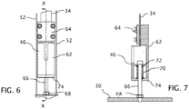
FIG. 6 is an enlarged detail view of area A in the rear elevational view ofFIG. 4 showing a compliant connector. -
FIG. 7 is a cross-sectional view of the compliant connector taken along line x-x ofFIG. 6 . -
FIG. 8 is a schematic side elevational view of a portion of the drive system showing an alternative type of compliant connector. - A
multi-axis machine 10 depicted in one of many possible configurations of a measuring machine, includes anx-y stage 14 for horizontally translating atest piece 18 along X and Y coordinate axes and aslide mechanism 16 for vertically translating asensor 20 along a Z coordinate axis. Thex-y stage 14 is supported on amachine base 22. Theslide mechanism 16 is supported in aslide support 26 carried on acolumn 24. As a measuring machine, thesensor 20 can be arranged, for example, as a mechanical or optical probe for taking localized measurements or as an objective lens for capturing information over a wider area of thetest part 18. Other unseen portions of the sensor or other apparatus supporting the metrology functions of the machine can be housed in theslide support 26 within which theslide mechanism 16 in translatable. - The measuring
machine 10 can be arranged with other combinations of translational axes relatively moving one or the other of thetest piece 18 and thesensor 20, and one or more rotational axes can be added for relatively rotating or pivoting one or the other of thetest piece 18 and thesensor 20. However, for purposes of certain embodiments, theslide mechanism 16 has a vertically displaceable mass influenced by the force of gravity. That is, if not otherwise restrained, theslide mechanism 16 would tend to move under force of gravity. - A counterbalance and drive system for the vertically
displaceable slide mechanism 16 is shown inFIGS. 2-7 . Theslide mechanism 16, where shown, is depicted in phantom lines, and similar to other translatable stages is preferably guided for motion along the Z axis by suitable rails or ways. Acounterweight 30 for theslide mechanism 16 is also mounted for linear motion along the Z axis. For example, thecounterweight 30 can be arranged to track along vertical guide rails 32. Since thecounterweight 30 is suspended for movement along a vertical axis and only requires confinement to prevent swinging in the event themachine 10 is jarred, the guidance system for the counterweight can be loose and not in immediate contact with the guide rails 32. However, if the counterweight were to be intended for displacement along an inclined axis or were to be supported by another machine axis subject to motion, thecounterweight 30 could be arranged with conventional bearing surfaces for more securely engaging the guide rails 30. - One end of a
linear timing belt 34, of appropriate size for the application, is attached directly to theslide mechanism 16, preferably anchored at or very near the center of gravity of theslide mechanism 16. A length of thelinear timing belt 34 is threaded over or around timingpulleys 36 andidler pulleys 38 as needed in the system design to travel to a location that is convenient to place adrive pulley 40 intended to be driven directly or indirectly by adrive motor 42, which is shown in phantom line. From thedrive pulley 40, the length of the timing belt can be further threaded over or around a timingpulley 44 and any number of other pulleys needed to travel to a location convenient for suspending thecounterweight 30. However, instead of attaching the opposite end to thelinear timing belt 34 directly to thecounterweight 30, the opposite end of thetiming belt 34 is attached to acompliant connector 46, which is in turn attached to thecounterweight 30, preferably at or very near the center of gravity of thecounterweight 30. - Thus, in the embodiment shown, the
timing belt 34 together with thecompliant connector 46 forms aflexible connector 48 extending from theslide mechanism 16 to thecounterweight 30. Thetiming belt 34 exhibits flexibility for allowing the timing belt to bend, i.e., wrap, around thepulleys compliant connector 46 exhibits longitudinal flexibility to accommodate limited variations in the length of theflexible connector 48 between thetiming belt 34 and thecounterweight 30. The various pulleys 36, 38, 40, and 44 suspend theflexible connector 48 from a machine mount, such as theslide support 26 orcolumn 24. Thetiming belt 34 and drive pulley are preferably toothed for efficiently converting rotary to translational motion. However, other types of drives could also be used including combinations of a chain and sprockets or a perforated metal tape and pulleys with bull nose pins. - Also attached to the
slide mechanism 16 near thelinear timing belt 34 is one end of acable 52, which is made of steel braiding or other material that is flexible for accomodating a limited amount of bending but is of adequate strength to support tensile loading without stretching in length. A length of thecable 52 is threaded over or around a series of groovedidler pulleys 54a to reach thecounterweight 30. At thecounterweight 30, thecable 52 wraps around one or more grooved idler pulleys, such as the groovedidler pulley 56 seen inFIG 4 , that are mounted to thecounterweight 30 to redirect a further length of thecable 52 along a similar return path to theslide mechanism 16, where an opposite end of thecable 52 is attached to theslide mechanism 16. - The return path for the
cable 52 is defined by a series of groovedidler pulleys 54b, which are mounted coaxially with the groovedidler pulleys 54a. Thepulley 56 displaces thecable 52 to either side of the of thetiming belt 34 and thecompliant coupling 46, and the coaxially mounted pairs ofidler pulleys cable 52, such that the opposite ends of the cable 54 are attached to theslide mechanism 16 on either side of thetiming belt 34. Thus, the two ends of thecable 52 straddling thetiming belt 34 allow both thecable 52 and thetiming belt 34 to be attached to theslide mechanism 16, preferably at or very near the center of gravity of theslide mechanism 16. Similarly, thepulley 56 can be mounted within thecounterbalance 30 in a position of alignment with the mounting of thecompliant connector 46 so that both mountings are preferably at or very near the center of gravity of thecounterbalance 30 so as not to induce any tilting or twisting of theslide mechanism 16 or thecounterweight 30. - The paired series of
pulleys cable 52 from a machine mount, such as theslide support 26 orcolumn 24. Thedouble length cable 52, as so suspended, forms aflexible connector 58 interconnecting theslide mechanism 16 and thecounterweight 30 so that a gravitational force acting on theslide mechanism 16 is at least partially opposed by a gravitational force acting on thecounterweight 30. In addition, one or both ends of thecable 52 are attached to theslide mechanism 16 with a means to adjust the overall length of thecable 52 to allow for proper adjustment of the relative length of thecompliant connector 46. Although theflexible connector 58 is formed as acable 52, theflexible connector 58 can take a variety of other forms including as a chain or belt arranged for carrying the desired tensile loads. - As particularly shown in
FIG. 7 , thelinear timing belt 34 is clamped to ahousing 62 of thecompliant connector 46 viabelt clamp plate 64. Abolt 66 extends through thehousing 62 into threaded engagement with thecounterweight 30.Jam nut 68 locks thebolt 66 in engagement with thecounterweight 30. Along a length of thebolt 66 within thehousing 62, acompression spring 70 extends from aspacer washer 72 at a head end of thebolt 66 to aspring capture plate 74 at the bottom of thehousing 62. - The spring force exerted by the
compression spring 16 places thetiming belt 34 under an amount of tension, which is considerably less than the amount of tension required to lift the full weight of thecounterbalance 30 but is preferably sufficient to prevent thetiming belt 34 from becoming slack or skipping teeth on thedrive pulley 40 during the raising or lowering of theslide mechanism 16. In addition, thecompression spring 70 is preferably compressible over a length that allows thetiming belt 34 to be overdriven through a distance capable triggering a stop condition interrupting further travel of thetiming belt 34 before thecompression spring 70 becomes fully compressed. - Under control of the
drive motor 42 via thetiming belt 34, theslide mechanism 16 can be raised or lowered by prescribed amounts while thecounterweight 30 is correspondingly lowered or raised via thecable 52. Since thecable 52 has a fixed length that remains under tension by the offsetting weights of theslide mechanism 16 and thecounterweight 30, thecompliant coupler 46 also tends to remain at the same length with thecompression spring 70 exhibiting the desired amount of tension along thetiming belt 34 between thedrive pulley 40 and thecounterweight 30. - If the
slide mechanism 16 encounters an obstruction while being lowered and can no longer move downward, thedrive motor 42 tends to continue to push thetiming belt 34 towards theslide mechanism 16 creating slack in thetiming belt 34 between thedrive pulley 40 and theslide mechanism 16. Between the drive pulley 49 and thecounterweight 30, the overdriving of thetiming belt 34 tends to lift thehousing 62 of thecompliant connector 46 further compressing thecompression spring 70, thereby extending the length of theflexible connector 48. - Thus, instead of lifting the
counterweight 30, which would disengage thecounterweight 30 from theslide mechanism 16 allowing all of the weight of theslide mechanism 16 to rest upon the obstruction, thecompliant connector 46 accommodates some overdriving of thetiming belt 34 so that any increase in the lifting force applied to thecounterweight 30 by thetiming belt 34 is limited to any additional spring force accompanying the further compression of thecompression spring 70. Preferably, the increase in spring force with the further compression of thecompression spring 70 is minimal to maintain no more than a desired amount of tension in thetiming belt 34 and to avoid any significant increase in the lifting force on thecounterweight 30, which would cancel out some of the desired counterbalance effect otherwise provided thecable 52. - To limit the amount of permitted overtravel of the
timing belt 34 to within a range of compliance of thecompliant connector 46, e.g., to within the range of compression of thecompression spring 70, a control loop is preferably provided that responds to an excess position error by stopping thedrive motor 42. As a part of such a control loop, one ormore position sensors timing belt 34 with respect to theslide mechanism 16 in which the displacement of thetiming belt 34 by thedrive motor 42 exceeds the displacement of theslide mechanism 16. Thesensor 90 monitors the translational position of theslide mechanism 16 along the Z axis. Thesensor 92 monitors the rotational position of thedrive motor 42 for determining an expected displacement of thetiming belt 34. Acontroller 94, which is connected to bothsensors drive motor 42, responds to detected overdriving of thetiming belt 34, as a disparity between the displacements of thetiming belt 34 and theslide mechanism 16, by stopping thedrive motor 42. The overdrive condition is preferably detected within the limited range of compliance of thecompliant connector 46 through which excess travel of thetiming belt 34 can be accommodated without cancelling out the desired counterbalance effects of thecable 52. - Once the
machine 10 is in such a stop condition, theslide mechanism 16 can be easily manually lifted because thecounterweight 30 is still effective through thecable 52 for offsetting the weight of theslide mechanism 16. Once theslide mechanism 16 is lifted, the obstruction can be moved out of the way and theslide mechanism 16 can then be manually lowered back down to its intended positon where there is no slack in thetiming belt 34 and themachine 10 can be put back into run mode to reinstate the desired drive motion. - While the compliant coupler exhibits a range of compliance sufficient to accommodate an amount of overtravel by the
timing belt 34 required to detect an overdrive condition and stop further overtravel of thetiming belt 34, the range of compliance is preferably limited as a further failsafe feature. For example, thecompression spring 70 preferably compresses down to a solid height at which further compression is ended. When thespring 70 has fully compressed, no further displacement between thehousing 62 and the bolted connection to thecounterweight 30 is possible and theflexible connector 48 is no longer extendible in length. Thus, should a break occur in theflexible connection 58 supported by thecable 52 between theslide mechanism 16 and thecounterweight 30, theflexible connection 48 is extendible to a maximum length at which the flexible connection functions as a part of a backup counterbalance system interconnecting theslide mechanism 16 and thecounterweight 30 so that the gravitational force acting on theslide mechanism 16 remains at least partially opposed by the gravitational force acting on thecounterweight 30. - As a part of a failsafe system, the
timing belt 34 andcompliant connector 46 are preferably designed to withstand the tension required to bear the weight of both theslide mechanism 16 and thecounterweight 30. As so counterbalanced, thedrive motor 42 can continue to operate to move theslide mechanism 16 to a safe position. A sensor in contact with thecable 52 can be used to detect a break in thecable 52 or its connections to theslide mechanism 16 andcounterweight 30 for directing themachine 10 to enter a safe mode. - The
compliant connector 46 can take a variety of forms as a tensioner for thetiming belt 34, including arranging for other forms of resilience for providing the desired tension. Other arrangements of stops can also be used for limiting the range of compliance. For example, a tension spring can be used together with a separate physical stop to limit the extension of the tension spring. - Instead of tensioning the
timing belt 34 by resilient forces acting to contract the length of theflexible connector 48, tension can be applied to thetiming belt 34 by stretching the length of the pathway over which thetiming belt 34 is arranged to travel between theslide mechanism 16 and thecounterweight 30. For example,FIG. 8 depicts acompliant connector 76 as different form of tensioner for applying a lateral force against thetiming belt 34 in a position located between thedrive pulley 40 and timingpulley 44. Idler pulleys 78 direct thetiming belt 34 around atensioner pulley 80 that is rotatably mounted at one end of apivot arm 82. Apivot 84 attaches thepivot arm 82 to a machine mount, such as theslide support 26 orcolumn 24, for displacing thetensioner pulley 80 relative to the idler pulleys 78. Acompression spring 86 engages a remote end of thepivot arm 82 for urging thetensioner pulley 80 away from the idler pulleys 78 to preload thetiming belt 34 with a desired amount of tension. Thecompression spring 86 also works against a machine mount, such as theslide support 26 orcolumn 24, to support the desired amount of force against thepivot arm 82. - With the alternative compliant connector arrangement of
FIG. 8 for tensioning thetiming belt 34, thetiming belt 34 can be connected directly to thecounterweight 30, such as with an appropriate clamping mechanism, without providing any resilient adjustment to the length oftiming belt 38 or any other portion of theflexible connector 48. If thetiming belt 34 is subjected to overtravel, such as when theslide mechanism 16 might encounter an obstacle while being lowered, any additional tension that might be imparted by thedrive motor 42 toward lifting thecounterweight 30 is first absorbed by thecompression spring 86, which compresses to allow thetensioner pulley 80 to displace and thereby shorten the pathway for thetiming belt 34 by the amount of the overtravel. - The supported range of displacement until the compression spring is compressed to a solid height is preferably sufficient to accommodate an amount of overtravel by the
timing belt 34 required to detect an overdrive condition and stop further overtravel of thetiming belt 34. Within the range at which thetensioner pulley 80 is displaceable, thecable 52 remains taught for continuing to counterbalance the weight of theslide mechanism 16 against the weight of thecounterweight 30, even while theslide mechanism 16 rests upon an obstruction. - A limit to the compliance of the
compliant connector 76 set by a solid stop between the remote end of thepivot arm 82 and the machine mount also contributes to a failsafe system for maintaining a counterbalance between theslide mechanism 16 and thecounterweight 30 even if thecable 52 or any other portion of theflexible connector 58 were to break. Once the stop is reached and the length of the pathway for thetiming belt 34 cannot further contract, tension can increase along thetiming belt 34 as a substitute for the tension along thecable 52 to support a backup counterbalance system interconnecting theslide mechanism 16 and thecounterweight 30 so that the gravitational force acting on theslide mechanism 16 remains at least partially opposed by the gravitational force acting on thecounterweight 30. As so counterbalanced, thedrive motor 42 can continue to operate to move theslide mechanism 16 to a safe position.
Claims (15)
- A counterbalance and drive system for a machine slide mechanism comprising:a machine mount supporting a vertically displaceable slide mechanism (16) and a counterweight (30);a counterbalance system including a first flexible connector (58) suspended from the machine mount and interconnecting the slide mechanism and the counterweight so that a gravitational force acting on the slide mechanism is at least partially opposed by a gravitational force acting on the counterweight;and characterised by
a drive system including a second flexible connector (34) suspended from the machine mount and interconnecting the slide mechanism and the counterweight, the drive system including:a drive motor (42) operatively engaged along a length of the second flexible connector for vertically displacing the slide mechanism; anda compliant connector (46, 76) operating within a limited range of compliance imparts a regulated amount of tension along at least a portion of the length of the second flexible connector between the engagement of the drive motor and the counterweight. - The counterbalance and drive system of claim 1 further comprising one or more sensors (90, 92) for detecting an overdriving of the second flexible connector (34) with respect to the slide mechanism (16) in which the displacement of the second flexible connector by the drive motor (42) exceeds the displacement of the slide mechanism,
optionally wherein the compliant connector (46, 76) is relatively displaceable within the limited range of compliance to accommodate the overdriving of the second flexible connector without relatively displacing the counterweight (30) with respect to the slide mechanism so that the gravitational force acting on the slide mechanism remains at least partially opposed by a gravitational force acting on the counterweight through the first flexible connector (58). - The counterbalance of claim 2 further comprising a controller (94) that responds to the detected overdriving of the second flexible connector (34) to interrupt further displacement of the second flexible connector with respect to the displacement of the slide mechanism (16) within the limited range of compliance,
optionally wherein the one or more sensors include a first sensor (90) for measuring displacement of the slide mechanism and a second sensor (92) for measuring displacement of the second flexible connector as driven by the drive motor, and the controller is arranged to respond to differences between the measured displacement of the slide mechanism and the measured displacement of the second flexible connector to interrupt movement imparted by the drive motor (42) to the second flexible connector. - The counterbalance and drive system of any one of the preceding claims in which the regulated amount of tension imparted by the compliant connector (46, 76) within the limited range of compliance applies a lifting force on the counterbalance that only partially counteracts the gravitational force acting on the counterweight (30),
optionally wherein the compliant connector is further arranged to operate beyond the limited range of compliance as a part of a failsafe mechanism whereby in response to a break in the connection between slide mechanism (16) and the counterweight provided by the first flexible connector (58), the second flexible connector (34) functions as a part of a backup counterbalance system interconnecting the slide mechanism and the counterweight so that the gravitational force acting on the slide mechanism remains at least partially opposed by the gravitational force acting on the counterweight,
preferably wherein the compliant connector further includes a spring (70, 86) that imparts the regulated amount of tension within the limited range of compliance and a stop through which the second flexible connector interconnects the slide mechanism and the counterweight beyond the limited range of compliance so that a further amount of tension can be conveyed by the second flexible connector corresponding to a lifting force on the counterbalance that more fully counteracts the gravitational force acting on the counterweight. - The counterbalance and drive system of any one of the preceding claims in which the compliant connector (46) forms a part of the length of the second flexible connector (34) so that, within the limited range of compliance of the compliant connector, the second flexible connector is resiliently extendible by a limited amount between the drive motor (42) and the counterweight,
optionally wherein the compliant connector exerts a resilient contracting force along the length of the flexible connector within the limited range of compliance for drawing the flexible connector taut against the counterweight (30). - The counterbalance and drive system of claim 5 in which the compliant connector (46) includes a stop that limits the extension of the second flexible connector (34) beyond the limited range of compliance of the compliant connector.
- The counterbalance and drive system of claim 5 in which the compliant connector (46) includes:a first part connected at a first point along the length of the second flexible connector (34), a second part connected at a second point along the length of the flexible connector, and a resilient member that imparts the resilient force between the first and second parts within the limited range of compliance,optionally wherein the compliant connector includes a stop that limits relative movement between the first and second parts beyond the limited range of compliance.further optionally wherein the second point along the length of the second flexible connector corresponds to an end of the second flexible connector that is connected to the counterweight (30).
- The counterbalance and drive system of any one of claims 1 through 4 in which the compliant connector resiliently supports the second flexible connector (34) from the machine mount along the length of the second flexible connector between the engagement of the drive motor (42) and the counterweight (30),
optionally wherein the compliant connector (76) applies a resilient force normal to the length of the flexible connector within the limited range of compliance for drawing the flexible connector taut against the counterweight,
optionally wherein the compliant connector includes a first part (84) connected to the machine mount, a second part (82) in engagement with a side of the second flexible connector, and a resilient member (86) that imparts the resilient force between the first and second parts within the limited range of compliance, and
optionally wherein the compliant connector further includes a stop that limits relative movement between the first and second parts beyond the limited range of compliance. - The counterbalance and drive system of any one of the preceding claims in which the first flexible connector (58) and the second flexible connector (34) are both connected to the slide mechanism (16) at a center of gravity of the slide mechanism,
optionally wherein the first flexible connector and the second flexible connector are both connected to the counterweight (30) at a center of gravity of the counterweight. - The counterbalance and drive system of any one of the preceding claims in which the first flexible connector (58) has a length that extends between two ends, and a first portion of the length first flexible connector extends from a first of the two ends that is connected to the slide mechanism (16) to the counterweight (30) and a second portion of the first flexible connector extends from the counterweight to a second of the two ends that is connected to the slide mechanism,
optionally wherein a median portion of the length of the first flexible connector is connected to the counterweight through a bearing that maintains both a local physical separation and a balance of tensile forces between the first and second portions of the length of the first flexible connector, and
wherein the second flexible connector (34) optionally includes a first end connected to the slide mechanism between the first and second ends of the first flexible connector and a second end connected to the counterweight in alignment with the bearing that maintains the local physical separation between the first and second portions of the length of the first flexible connector. - A counterbalance and drive system for a machine slide mechanism comprising:a machine mount supporting a vertically displaceable slide mechanism (16) and a counterweight;a first flexible connector (58) suspended from the machine mount interconnecting the slide mechanism and the counterweight for forming a counterbalance such that a gravitational force acting on the slide mechanism is at least partially opposed by a gravitational force acting on the counterweight through a transmission of a first amount of tension by the first flexible connector between the slide mechanism and the counterweight;and characterised bya second flexible connector (34) suspended from the machine mount interconnecting the slide mechanism and the counterweight;a drive motor (42) operatively engaged along a length of the second flexible connector for vertically displacing the slide mechanism;a tensioner (46) that imparts a second lesser amount of tension along a portion of the second flexible connector between the engagement of the drive motor and the counterweight to maintain the engagement between the drive motor and the second flexible connector.
- The counterbalance and drive system of claim 11 in which the lesser amount of tension imparted by the tensioner (46) applies a lifting force on the counterbalance that only partially counteracts the gravitational force acting on the counterweight (30),
optionally wherein the tensioner is further arranged together with the second flexible connector (34) as a part of a failsafe mechanism whereby in response to a break in the connection between slide mechanism and the counterweight provided by the first flexible connector, the second flexible connector functions as a part of a backup counterbalance system interconnecting the slide mechanism and the counterweight so that the gravitational force acting on the slide mechanism remains at least partially opposed by the gravitational force acting on the counterweight. - The counterbalance and drive system of claim 11 or claim 12 in which the tensioner (46) includes a resilient member that is displaceable within a limited range for imparting the lesser amount of tension along the second flexible connector,
optionally wherein the displacement of the resilient member is limited by a stop for conveying greater amounts of tension along the second flexible connector. - The counterbalance and drive system of claim 11 or claim 12 in which the tensioner includes either of:a first part connected at a first point along the length of the second flexible connector, a second part connected at a second point along the length of the flexible connector, and a resilient member that imparts the resilient force between the first and second parts; ora first part connected to the machine mount, a second part in engagement with a side of the second flexible connector, and a resilient member that imparts the resilient force between the first and second parts,optionally wherein the tensioner includes a stop that limits relative movement between the first and second parts.
- The counterbalance and drive system of claim 11 further comprising one or more sensors (90, 92) for detecting an overdriving of the second flexible connector with respect to the slide mechanism in which the displacement of the second flexible connector by the drive motor exceeds the displacement of the slide mechanism,
optionally wherein the tensioner includes a resilient member that is relatively displaceable within a limited range to accommodate the overdriving of the second flexible connector without relatively displacing the counterweight with respect to the slide mechanism so that the gravitational force acting on the slide mechanism remains at least partially opposed by a gravitational force acting on the counterweight through the first flexible connector,
and optionally wherein the counterbalance further comprises a controller (94) that responds to the detected overdriving of the second flexible connector to interrupt further displacement of the second flexible connector with respect to the displacement of the slide mechanism with the limited displacement range of the resilient member.
Applications Claiming Priority (2)
| Application Number | Priority Date | Filing Date | Title |
|---|---|---|---|
| US15/051,287 US9878413B2 (en) | 2016-02-23 | 2016-02-23 | Counterbalance and drive system for machine slide mechanism |
| PCT/US2016/068198 WO2017146810A1 (en) | 2016-02-23 | 2016-12-22 | Counterbalance and drive system for machine slide mechanism |
Publications (2)
| Publication Number | Publication Date |
|---|---|
| EP3414046A1 EP3414046A1 (en) | 2018-12-19 |
| EP3414046B1 true EP3414046B1 (en) | 2020-02-12 |
Family
ID=57797021
Family Applications (1)
| Application Number | Title | Priority Date | Filing Date |
|---|---|---|---|
| EP16826270.7A Active EP3414046B1 (en) | 2016-02-23 | 2016-12-22 | Counterbalance and drive system for machine slide mechanism |
Country Status (4)
| Country | Link |
|---|---|
| US (1) | US9878413B2 (en) |
| EP (1) | EP3414046B1 (en) |
| JP (1) | JP6591042B2 (en) |
| WO (1) | WO2017146810A1 (en) |
Families Citing this family (3)
| Publication number | Priority date | Publication date | Assignee | Title |
|---|---|---|---|---|
| US9878413B2 (en) * | 2016-02-23 | 2018-01-30 | Quality Vision International, Inc. | Counterbalance and drive system for machine slide mechanism |
| CN110802438B (en) * | 2019-11-15 | 2022-01-25 | 浙江特普机床制造有限公司 | Novel special counter weight mechanism of combined type lathe |
| CN113091677B (en) * | 2021-05-10 | 2025-06-24 | 山东杰控电气技术有限公司 | A gravity-driven flexible reciprocating dynamic length measuring mechanism |
Family Cites Families (15)
| Publication number | Priority date | Publication date | Assignee | Title |
|---|---|---|---|---|
| JPS5437512Y2 (en) | 1976-04-09 | 1979-11-09 | ||
| US4093259A (en) | 1977-05-02 | 1978-06-06 | Caterpillar Tractor Co. | Vehicle having resiliently mounted counterweight |
| JPS5467947A (en) | 1977-11-11 | 1979-05-31 | Hitachi Ltd | Driver for elevator controller |
| IT1163536B (en) | 1983-06-17 | 1987-04-08 | Innocenti Santeustacchio Spa | DEVICE FOR BALANCING THE WEIGHT OF A VERTICALLY MOBILE HEAD OF A MACHINE TOOL |
| US4719811A (en) | 1985-02-25 | 1988-01-19 | Rota-Flex Corporation | Well pumping unit with counterweight |
| GB8808283D0 (en) * | 1988-04-08 | 1988-05-11 | Lk Tool Co Ltd | Component control apparatus in measuring machines |
| DE3823042A1 (en) * | 1988-07-07 | 1990-01-11 | Zeiss Carl Fa | COORDINATE MEASURING DEVICE |
| US6058618A (en) * | 1997-09-09 | 2000-05-09 | Giddings & Lewis, Inc. | Coordinate measuring machine |
| GB9724453D0 (en) * | 1997-11-20 | 1998-01-14 | Renishaw Plc | Measuring or positioning machine |
| US6138799A (en) | 1998-09-30 | 2000-10-31 | Otis Elevator Company | Belt-climbing elevator having drive in counterweight |
| GB201007186D0 (en) * | 2010-04-30 | 2010-06-09 | Renishaw Plc | Changeable task module counterweight |
| US8375594B1 (en) * | 2010-06-09 | 2013-02-19 | Bruker Nano Inc. | Pneumatic counterbalance for optical head gantry |
| ES2525099B1 (en) * | 2013-05-16 | 2015-09-18 | Unimetrik, S.A. | REMOVABLE NUMERICAL CONTROL MACHINE |
| US10371507B2 (en) * | 2013-07-19 | 2019-08-06 | Nikon Corporation | Shape measurement device, structural object production system, shape measurement method, structural object production method, shape measurement program, and recording medium |
| US9878413B2 (en) * | 2016-02-23 | 2018-01-30 | Quality Vision International, Inc. | Counterbalance and drive system for machine slide mechanism |
-
2016
- 2016-02-23 US US15/051,287 patent/US9878413B2/en not_active Expired - Fee Related
- 2016-12-22 JP JP2018504966A patent/JP6591042B2/en not_active Expired - Fee Related
- 2016-12-22 EP EP16826270.7A patent/EP3414046B1/en active Active
- 2016-12-22 WO PCT/US2016/068198 patent/WO2017146810A1/en not_active Ceased
Non-Patent Citations (1)
| Title |
|---|
| None * |
Also Published As
| Publication number | Publication date |
|---|---|
| US9878413B2 (en) | 2018-01-30 |
| EP3414046A1 (en) | 2018-12-19 |
| WO2017146810A1 (en) | 2017-08-31 |
| US20170239769A1 (en) | 2017-08-24 |
| JP2019501336A (en) | 2019-01-17 |
| JP6591042B2 (en) | 2019-10-16 |
Similar Documents
| Publication | Publication Date | Title |
|---|---|---|
| US7926622B2 (en) | Lift cable slack monitoring device and method | |
| KR101343894B1 (en) | Buffered storage and transport device for tool utilization | |
| US20040228710A1 (en) | Article conveying apparatus | |
| JP5187425B2 (en) | robot | |
| US20040228709A1 (en) | Article conveying apparatus | |
| US9878413B2 (en) | Counterbalance and drive system for machine slide mechanism | |
| KR100270859B1 (en) | Carrier and Prober Using It | |
| KR102047285B1 (en) | Antidrop module of overhead hoist transport | |
| US6766996B1 (en) | Manipulator | |
| CN110023225B (en) | Elevator scale device | |
| JP2011240448A (en) | Wire-driven robot | |
| CN121553873B (en) | Automatic leveling and winding drum rope winding preventing device for stacker cargo bed | |
| US10633191B2 (en) | Movable platform for a skillet conveyor system of a vehicle assembly line | |
| JP7562407B2 (en) | ROBOT AND METHOD FOR CONTROLLING ROBOT | |
| JP7568191B2 (en) | Article lifting device | |
| CN110605521A (en) | Welding device | |
| KR101185888B1 (en) | Elevating apparatus | |
| KR101012254B1 (en) | Elevator suspension system | |
| CN116873436B (en) | Panel handling device and panel warehouse system | |
| KR102888454B1 (en) | Hand unit and vehicle having the same | |
| CN116878851B (en) | A drawer slide life detection device | |
| JP2025098377A (en) | Speed governor and elevator | |
| JP2707941B2 (en) | Elevator compensation rope tensioner equipment | |
| RU2717872C2 (en) | Inclined hoist and operating method of inclined hoist | |
| CN222964681U (en) | A collision monitoring device |
Legal Events
| Date | Code | Title | Description |
|---|---|---|---|
| STAA | Information on the status of an ep patent application or granted ep patent |
Free format text: STATUS: UNKNOWN |
|
| STAA | Information on the status of an ep patent application or granted ep patent |
Free format text: STATUS: THE INTERNATIONAL PUBLICATION HAS BEEN MADE |
|
| PUAI | Public reference made under article 153(3) epc to a published international application that has entered the european phase |
Free format text: ORIGINAL CODE: 0009012 |
|
| STAA | Information on the status of an ep patent application or granted ep patent |
Free format text: STATUS: REQUEST FOR EXAMINATION WAS MADE |
|
| 17P | Request for examination filed |
Effective date: 20180911 |
|
| AK | Designated contracting states |
Kind code of ref document: A1 Designated state(s): AL AT BE BG CH CY CZ DE DK EE ES FI FR GB GR HR HU IE IS IT LI LT LU LV MC MK MT NL NO PL PT RO RS SE SI SK SM TR |
|
| AX | Request for extension of the european patent |
Extension state: BA ME |
|
| DAV | Request for validation of the european patent (deleted) | ||
| DAX | Request for extension of the european patent (deleted) | ||
| GRAP | Despatch of communication of intention to grant a patent |
Free format text: ORIGINAL CODE: EPIDOSNIGR1 |
|
| STAA | Information on the status of an ep patent application or granted ep patent |
Free format text: STATUS: GRANT OF PATENT IS INTENDED |
|
| INTG | Intention to grant announced |
Effective date: 20190823 |
|
| GRAS | Grant fee paid |
Free format text: ORIGINAL CODE: EPIDOSNIGR3 |
|
| GRAA | (expected) grant |
Free format text: ORIGINAL CODE: 0009210 |
|
| STAA | Information on the status of an ep patent application or granted ep patent |
Free format text: STATUS: THE PATENT HAS BEEN GRANTED |
|
| AK | Designated contracting states |
Kind code of ref document: B1 Designated state(s): AL AT BE BG CH CY CZ DE DK EE ES FI FR GB GR HR HU IE IS IT LI LT LU LV MC MK MT NL NO PL PT RO RS SE SI SK SM TR |
|
| REG | Reference to a national code |
Ref country code: GB Ref legal event code: FG4D |
|
| REG | Reference to a national code |
Ref country code: CH Ref legal event code: EP |
|
| REG | Reference to a national code |
Ref country code: AT Ref legal event code: REF Ref document number: 1231460 Country of ref document: AT Kind code of ref document: T Effective date: 20200215 |
|
| REG | Reference to a national code |
Ref country code: CH Ref legal event code: NV Representative=s name: E. BLUM AND CO. AG PATENT- UND MARKENANWAELTE , CH |
|
| REG | Reference to a national code |
Ref country code: IE Ref legal event code: FG4D |
|
| REG | Reference to a national code |
Ref country code: DE Ref legal event code: R096 Ref document number: 602016029781 Country of ref document: DE |
|
| PG25 | Lapsed in a contracting state [announced via postgrant information from national office to epo] |
Ref country code: FI Free format text: LAPSE BECAUSE OF FAILURE TO SUBMIT A TRANSLATION OF THE DESCRIPTION OR TO PAY THE FEE WITHIN THE PRESCRIBED TIME-LIMIT Effective date: 20200212 Ref country code: NO Free format text: LAPSE BECAUSE OF FAILURE TO SUBMIT A TRANSLATION OF THE DESCRIPTION OR TO PAY THE FEE WITHIN THE PRESCRIBED TIME-LIMIT Effective date: 20200512 Ref country code: RS Free format text: LAPSE BECAUSE OF FAILURE TO SUBMIT A TRANSLATION OF THE DESCRIPTION OR TO PAY THE FEE WITHIN THE PRESCRIBED TIME-LIMIT Effective date: 20200212 |
|
| REG | Reference to a national code |
Ref country code: LT Ref legal event code: MG4D |
|
| REG | Reference to a national code |
Ref country code: NL Ref legal event code: MP Effective date: 20200212 |
|
| PG25 | Lapsed in a contracting state [announced via postgrant information from national office to epo] |
Ref country code: GR Free format text: LAPSE BECAUSE OF FAILURE TO SUBMIT A TRANSLATION OF THE DESCRIPTION OR TO PAY THE FEE WITHIN THE PRESCRIBED TIME-LIMIT Effective date: 20200513 Ref country code: IS Free format text: LAPSE BECAUSE OF FAILURE TO SUBMIT A TRANSLATION OF THE DESCRIPTION OR TO PAY THE FEE WITHIN THE PRESCRIBED TIME-LIMIT Effective date: 20200612 Ref country code: BG Free format text: LAPSE BECAUSE OF FAILURE TO SUBMIT A TRANSLATION OF THE DESCRIPTION OR TO PAY THE FEE WITHIN THE PRESCRIBED TIME-LIMIT Effective date: 20200512 Ref country code: LV Free format text: LAPSE BECAUSE OF FAILURE TO SUBMIT A TRANSLATION OF THE DESCRIPTION OR TO PAY THE FEE WITHIN THE PRESCRIBED TIME-LIMIT Effective date: 20200212 Ref country code: SE Free format text: LAPSE BECAUSE OF FAILURE TO SUBMIT A TRANSLATION OF THE DESCRIPTION OR TO PAY THE FEE WITHIN THE PRESCRIBED TIME-LIMIT Effective date: 20200212 Ref country code: HR Free format text: LAPSE BECAUSE OF FAILURE TO SUBMIT A TRANSLATION OF THE DESCRIPTION OR TO PAY THE FEE WITHIN THE PRESCRIBED TIME-LIMIT Effective date: 20200212 |
|
| PG25 | Lapsed in a contracting state [announced via postgrant information from national office to epo] |
Ref country code: NL Free format text: LAPSE BECAUSE OF FAILURE TO SUBMIT A TRANSLATION OF THE DESCRIPTION OR TO PAY THE FEE WITHIN THE PRESCRIBED TIME-LIMIT Effective date: 20200212 |
|
| PG25 | Lapsed in a contracting state [announced via postgrant information from national office to epo] |
Ref country code: ES Free format text: LAPSE BECAUSE OF FAILURE TO SUBMIT A TRANSLATION OF THE DESCRIPTION OR TO PAY THE FEE WITHIN THE PRESCRIBED TIME-LIMIT Effective date: 20200212 Ref country code: LT Free format text: LAPSE BECAUSE OF FAILURE TO SUBMIT A TRANSLATION OF THE DESCRIPTION OR TO PAY THE FEE WITHIN THE PRESCRIBED TIME-LIMIT Effective date: 20200212 Ref country code: SM Free format text: LAPSE BECAUSE OF FAILURE TO SUBMIT A TRANSLATION OF THE DESCRIPTION OR TO PAY THE FEE WITHIN THE PRESCRIBED TIME-LIMIT Effective date: 20200212 Ref country code: EE Free format text: LAPSE BECAUSE OF FAILURE TO SUBMIT A TRANSLATION OF THE DESCRIPTION OR TO PAY THE FEE WITHIN THE PRESCRIBED TIME-LIMIT Effective date: 20200212 Ref country code: PT Free format text: LAPSE BECAUSE OF FAILURE TO SUBMIT A TRANSLATION OF THE DESCRIPTION OR TO PAY THE FEE WITHIN THE PRESCRIBED TIME-LIMIT Effective date: 20200705 Ref country code: DK Free format text: LAPSE BECAUSE OF FAILURE TO SUBMIT A TRANSLATION OF THE DESCRIPTION OR TO PAY THE FEE WITHIN THE PRESCRIBED TIME-LIMIT Effective date: 20200212 Ref country code: SK Free format text: LAPSE BECAUSE OF FAILURE TO SUBMIT A TRANSLATION OF THE DESCRIPTION OR TO PAY THE FEE WITHIN THE PRESCRIBED TIME-LIMIT Effective date: 20200212 Ref country code: RO Free format text: LAPSE BECAUSE OF FAILURE TO SUBMIT A TRANSLATION OF THE DESCRIPTION OR TO PAY THE FEE WITHIN THE PRESCRIBED TIME-LIMIT Effective date: 20200212 Ref country code: CZ Free format text: LAPSE BECAUSE OF FAILURE TO SUBMIT A TRANSLATION OF THE DESCRIPTION OR TO PAY THE FEE WITHIN THE PRESCRIBED TIME-LIMIT Effective date: 20200212 |
|
| REG | Reference to a national code |
Ref country code: DE Ref legal event code: R097 Ref document number: 602016029781 Country of ref document: DE |
|
| REG | Reference to a national code |
Ref country code: AT Ref legal event code: MK05 Ref document number: 1231460 Country of ref document: AT Kind code of ref document: T Effective date: 20200212 |
|
| PLBE | No opposition filed within time limit |
Free format text: ORIGINAL CODE: 0009261 |
|
| STAA | Information on the status of an ep patent application or granted ep patent |
Free format text: STATUS: NO OPPOSITION FILED WITHIN TIME LIMIT |
|
| 26N | No opposition filed |
Effective date: 20201113 |
|
| PG25 | Lapsed in a contracting state [announced via postgrant information from national office to epo] |
Ref country code: IT Free format text: LAPSE BECAUSE OF FAILURE TO SUBMIT A TRANSLATION OF THE DESCRIPTION OR TO PAY THE FEE WITHIN THE PRESCRIBED TIME-LIMIT Effective date: 20200212 Ref country code: AT Free format text: LAPSE BECAUSE OF FAILURE TO SUBMIT A TRANSLATION OF THE DESCRIPTION OR TO PAY THE FEE WITHIN THE PRESCRIBED TIME-LIMIT Effective date: 20200212 |
|
| PG25 | Lapsed in a contracting state [announced via postgrant information from national office to epo] |
Ref country code: PL Free format text: LAPSE BECAUSE OF FAILURE TO SUBMIT A TRANSLATION OF THE DESCRIPTION OR TO PAY THE FEE WITHIN THE PRESCRIBED TIME-LIMIT Effective date: 20200212 Ref country code: SI Free format text: LAPSE BECAUSE OF FAILURE TO SUBMIT A TRANSLATION OF THE DESCRIPTION OR TO PAY THE FEE WITHIN THE PRESCRIBED TIME-LIMIT Effective date: 20200212 |
|
| PG25 | Lapsed in a contracting state [announced via postgrant information from national office to epo] |
Ref country code: MC Free format text: LAPSE BECAUSE OF FAILURE TO SUBMIT A TRANSLATION OF THE DESCRIPTION OR TO PAY THE FEE WITHIN THE PRESCRIBED TIME-LIMIT Effective date: 20200212 |
|
| REG | Reference to a national code |
Ref country code: BE Ref legal event code: MM Effective date: 20201231 |
|
| PG25 | Lapsed in a contracting state [announced via postgrant information from national office to epo] |
Ref country code: IE Free format text: LAPSE BECAUSE OF NON-PAYMENT OF DUE FEES Effective date: 20201222 Ref country code: LU Free format text: LAPSE BECAUSE OF NON-PAYMENT OF DUE FEES Effective date: 20201222 |
|
| PG25 | Lapsed in a contracting state [announced via postgrant information from national office to epo] |
Ref country code: TR Free format text: LAPSE BECAUSE OF FAILURE TO SUBMIT A TRANSLATION OF THE DESCRIPTION OR TO PAY THE FEE WITHIN THE PRESCRIBED TIME-LIMIT Effective date: 20200212 Ref country code: MT Free format text: LAPSE BECAUSE OF FAILURE TO SUBMIT A TRANSLATION OF THE DESCRIPTION OR TO PAY THE FEE WITHIN THE PRESCRIBED TIME-LIMIT Effective date: 20200212 Ref country code: CY Free format text: LAPSE BECAUSE OF FAILURE TO SUBMIT A TRANSLATION OF THE DESCRIPTION OR TO PAY THE FEE WITHIN THE PRESCRIBED TIME-LIMIT Effective date: 20200212 |
|
| PG25 | Lapsed in a contracting state [announced via postgrant information from national office to epo] |
Ref country code: MK Free format text: LAPSE BECAUSE OF FAILURE TO SUBMIT A TRANSLATION OF THE DESCRIPTION OR TO PAY THE FEE WITHIN THE PRESCRIBED TIME-LIMIT Effective date: 20200212 Ref country code: AL Free format text: LAPSE BECAUSE OF FAILURE TO SUBMIT A TRANSLATION OF THE DESCRIPTION OR TO PAY THE FEE WITHIN THE PRESCRIBED TIME-LIMIT Effective date: 20200212 |
|
| PG25 | Lapsed in a contracting state [announced via postgrant information from national office to epo] |
Ref country code: BE Free format text: LAPSE BECAUSE OF NON-PAYMENT OF DUE FEES Effective date: 20201231 |
|
| PGFP | Annual fee paid to national office [announced via postgrant information from national office to epo] |
Ref country code: GB Payment date: 20221103 Year of fee payment: 7 Ref country code: FR Payment date: 20221110 Year of fee payment: 7 Ref country code: DE Payment date: 20221025 Year of fee payment: 7 |
|
| PGFP | Annual fee paid to national office [announced via postgrant information from national office to epo] |
Ref country code: CH Payment date: 20230101 Year of fee payment: 7 |
|
| REG | Reference to a national code |
Ref country code: DE Ref legal event code: R119 Ref document number: 602016029781 Country of ref document: DE |
|
| REG | Reference to a national code |
Ref country code: CH Ref legal event code: PL |
|
| GBPC | Gb: european patent ceased through non-payment of renewal fee |
Effective date: 20231222 |
|
| PG25 | Lapsed in a contracting state [announced via postgrant information from national office to epo] |
Ref country code: DE Free format text: LAPSE BECAUSE OF NON-PAYMENT OF DUE FEES Effective date: 20240702 |
|
| PG25 | Lapsed in a contracting state [announced via postgrant information from national office to epo] |
Ref country code: GB Free format text: LAPSE BECAUSE OF NON-PAYMENT OF DUE FEES Effective date: 20231222 |
|
| PG25 | Lapsed in a contracting state [announced via postgrant information from national office to epo] |
Ref country code: FR Free format text: LAPSE BECAUSE OF NON-PAYMENT OF DUE FEES Effective date: 20231231 |
|
| PG25 | Lapsed in a contracting state [announced via postgrant information from national office to epo] |
Ref country code: CH Free format text: LAPSE BECAUSE OF NON-PAYMENT OF DUE FEES Effective date: 20231231 |
|
| PG25 | Lapsed in a contracting state [announced via postgrant information from national office to epo] |
Ref country code: GB Free format text: LAPSE BECAUSE OF NON-PAYMENT OF DUE FEES Effective date: 20231222 Ref country code: FR Free format text: LAPSE BECAUSE OF NON-PAYMENT OF DUE FEES Effective date: 20231231 Ref country code: DE Free format text: LAPSE BECAUSE OF NON-PAYMENT OF DUE FEES Effective date: 20240702 Ref country code: CH Free format text: LAPSE BECAUSE OF NON-PAYMENT OF DUE FEES Effective date: 20231231 |