EP3413629B1 - User device and communication method - Google Patents
User device and communication method Download PDFInfo
- Publication number
- EP3413629B1 EP3413629B1 EP17747443.4A EP17747443A EP3413629B1 EP 3413629 B1 EP3413629 B1 EP 3413629B1 EP 17747443 A EP17747443 A EP 17747443A EP 3413629 B1 EP3413629 B1 EP 3413629B1
- Authority
- EP
- European Patent Office
- Prior art keywords
- frequency band
- user equipment
- prb
- information
- base station
- Prior art date
- Legal status (The legal status is an assumption and is not a legal conclusion. Google has not performed a legal analysis and makes no representation as to the accuracy of the status listed.)
- Active
Links
- 238000000034 method Methods 0.000 title claims description 69
- 238000004891 communication Methods 0.000 title claims description 50
- 238000012545 processing Methods 0.000 description 30
- 238000010586 diagram Methods 0.000 description 21
- 230000006870 function Effects 0.000 description 18
- 101150071746 Pbsn gene Proteins 0.000 description 17
- 230000008569 process Effects 0.000 description 15
- 230000005540 biological transmission Effects 0.000 description 10
- 238000006243 chemical reaction Methods 0.000 description 8
- 230000011664 signaling Effects 0.000 description 6
- 239000000969 carrier Substances 0.000 description 4
- 238000005516 engineering process Methods 0.000 description 3
- 230000007774 longterm Effects 0.000 description 3
- 230000007704 transition Effects 0.000 description 3
- 230000003321 amplification Effects 0.000 description 2
- 230000008901 benefit Effects 0.000 description 2
- 238000013507 mapping Methods 0.000 description 2
- 238000003199 nucleic acid amplification method Methods 0.000 description 2
- 230000009467 reduction Effects 0.000 description 2
- 230000000717 retained effect Effects 0.000 description 2
- 230000008054 signal transmission Effects 0.000 description 2
- 101150096310 SIB1 gene Proteins 0.000 description 1
- 101150039363 SIB2 gene Proteins 0.000 description 1
- 230000001413 cellular effect Effects 0.000 description 1
- 239000003795 chemical substances by application Substances 0.000 description 1
- 230000000694 effects Effects 0.000 description 1
- 239000006249 magnetic particle Substances 0.000 description 1
- 238000012423 maintenance Methods 0.000 description 1
- 239000000203 mixture Substances 0.000 description 1
- 230000003287 optical effect Effects 0.000 description 1
- 238000005457 optimization Methods 0.000 description 1
- 230000004044 response Effects 0.000 description 1
- 238000000926 separation method Methods 0.000 description 1
- 239000013589 supplement Substances 0.000 description 1
- 230000000153 supplemental effect Effects 0.000 description 1
Images


Classifications
-
- H—ELECTRICITY
- H04—ELECTRIC COMMUNICATION TECHNIQUE
- H04W—WIRELESS COMMUNICATION NETWORKS
- H04W72/00—Local resource management
- H04W72/04—Wireless resource allocation
- H04W72/044—Wireless resource allocation based on the type of the allocated resource
- H04W72/0453—Resources in frequency domain, e.g. a carrier in FDMA
-
- H—ELECTRICITY
- H04—ELECTRIC COMMUNICATION TECHNIQUE
- H04W—WIRELESS COMMUNICATION NETWORKS
- H04W56/00—Synchronisation arrangements
- H04W56/0005—Synchronisation arrangements synchronizing of arrival of multiple uplinks
-
- H—ELECTRICITY
- H04—ELECTRIC COMMUNICATION TECHNIQUE
- H04L—TRANSMISSION OF DIGITAL INFORMATION, e.g. TELEGRAPHIC COMMUNICATION
- H04L5/00—Arrangements affording multiple use of the transmission path
- H04L5/0091—Signalling for the administration of the divided path, e.g. signalling of configuration information
- H04L5/0094—Indication of how sub-channels of the path are allocated
-
- H—ELECTRICITY
- H04—ELECTRIC COMMUNICATION TECHNIQUE
- H04L—TRANSMISSION OF DIGITAL INFORMATION, e.g. TELEGRAPHIC COMMUNICATION
- H04L5/00—Arrangements affording multiple use of the transmission path
- H04L5/003—Arrangements for allocating sub-channels of the transmission path
- H04L5/0044—Allocation of payload; Allocation of data channels, e.g. PDSCH or PUSCH
-
- H—ELECTRICITY
- H04—ELECTRIC COMMUNICATION TECHNIQUE
- H04L—TRANSMISSION OF DIGITAL INFORMATION, e.g. TELEGRAPHIC COMMUNICATION
- H04L5/00—Arrangements affording multiple use of the transmission path
- H04L5/003—Arrangements for allocating sub-channels of the transmission path
- H04L5/0053—Allocation of signalling, i.e. of overhead other than pilot signals
-
- H—ELECTRICITY
- H04—ELECTRIC COMMUNICATION TECHNIQUE
- H04W—WIRELESS COMMUNICATION NETWORKS
- H04W48/00—Access restriction; Network selection; Access point selection
- H04W48/08—Access restriction or access information delivery, e.g. discovery data delivery
- H04W48/10—Access restriction or access information delivery, e.g. discovery data delivery using broadcasted information
-
- H—ELECTRICITY
- H04—ELECTRIC COMMUNICATION TECHNIQUE
- H04W—WIRELESS COMMUNICATION NETWORKS
- H04W88/00—Devices specially adapted for wireless communication networks, e.g. terminals, base stations or access point devices
- H04W88/02—Terminal devices
Definitions
- the present invention relates to user equipment and a communication method.
- LTE Long Term Evolution
- Non-Patent Document 1 For a UMTS (Universal Mobile Telecommunications System) network, specifications of Long Term Evolution (LTE: Long Term Evolution) have been developed so as to achieve objects, such as higher data rate and lower latency (Non-Patent Document 1). Furthermore, in order to achieve objects of adopting a wider bandwidth and a higher data rate, successor systems of LTE (which are also referred to as LTE-A (LTE-Advanced), FRA (Future Radio Access), 4G, 5G, and so forth, for example) have been studied.
- LTE-A LTE-Advanced
- FRA Full Radio Access
- M2M Machine-to-Machine
- 3GPP Third Generation Partnership Project
- MTC Machine Type Communication
- Non-Patent Document 2 a cellular system for the Machine-to-Machine communication
- a MTC terminal since it is likely that a MTC terminal is to be installed in a location deep inside a building, or a location where it is difficult to perform radio communication due to large building entrance loss, such as underground, a MTC terminal has been studied, an object of which is to extend coverage. Based on the above two examples, terminals are classified into the following four patterns:
- the MTC Terminal (MTC UE (User Equipment)) is considered to be used in a wide range of fields, such as electric meters, gas meters, vending machines, vehicles, and other industrial devices.
- Patent Document 1 WO 2015/024858 A1 _[Non-Patent Document]
- Non-Patent Document 3 a study related to a MTC terminal has been started that is for achieving further cost reduction by restricting a bandwidth to be used to be less than or equal to 180 kHz, which corresponds to a band width of 1 PRB (Physical Resource Block) (Non-Patent Document 3).
- the WI (Work Item) related to this study is referred to as NB-IoT (Narrow Band-Internet of Things).
- the NB-IoT aims to achieve coverage expansion that is greater than or equal to 20 dB compared to a usual GPRS (General Packet Radio Service) terminal, and that is greater than or equal to 20 dB compared to a category 1 terminal specified in usual LTE.
- GPRS General Packet Radio Service
- Patent Document 1 describes M2M communications.
- the UE acquires system information on the anchor carrier.
- the system information includes the number of subcarriers, information about an identity and a frequency location of each subcarriers.
- Non-Patent Document 5 describes multiple carrier operation for NB-IoT. It is proposed that a single so-called anchor NB-IoT carrier could be defined which carries the NB-PSS, NB-SSS, NB-PBCH and common control signaling such as paging and system information for all NB-IoT carriers of an LTE donor cell.
- Non-Patent Document 6 describes multi-Band NB-IoT. It is proposed that the NB-PSS/NB-SSS and NB-PBCH channels are conveyed by the anchor PRB only. The information of NB-IoT bands can be included by master/system information broadcast.
- Non-Patent Document 7 describes multi-Band NB-IoT, the anchor carrier carrying NB-PSS/NB-SSS/NB-PBCH/NB-SIB.
- the information on NB-IoT bands is indicated via RRC signalling.
- a technique that allows user equipment to obtain, in addition to the information about the frequency band to be used as the starting point (the Anchor PRB), the information about the frequency band to be additionally used (the Additional PRB).
- a first scenario is to configure the bandwidth to be used within a bandwidth that is actually available for communication (e.g., 9 MHz) in a LTE system bandwidth (e.g., 10 MHz) (a scenario using in-band);
- a second scenario is to configure the bandwidth to be used in a bandwidth corresponding to a guard band in the LTE system bandwidth (a scenario using a guard band);
- a third scenario is to use a bandwidth dedicated for the NB-IoT.
- FIG. 1 shows configuration examples of the bandwidth to be used in the first scenario and the second scenario.
- NB-IoT for the scenarios using the in-band and the guard band, a method has been studied which is for performing communication by configuring a plurality of bandwidths to be used. Specifically, for example, as illustrated in (1) of FIG. 2 , a method has been studied such that synchronization signals (NB-PSS, NB-SSS) and broadcast information (NB-PBSH) are to be transmitted in each of a plurality of bandwidths to be used, so that user equipment can visit (camp on) any bandwidth to be used.
- NB-PSS synchronization signals
- NB-SSS synchronization signals
- NB-PBSH broadcast information
- a method has been studied such that the synchronization signals (NB-PSS, NB-SSS) and the broadcast information (NB-PBCH) are to be transmitted only in a part of bandwidths to be used (which is referred to as "Anchor PRB (Anchor PRB), hereinafter) of the bandwidths to be used, and the synchronization signals and the broadcast information are not to be transmitted in the other bandwidths to be used (which is referred to as "Additional PRB (Additional PRB), hereinafter), so that a bandwidth to be used, which can be visited by user equipment, is to be restricted.
- the user equipment belonging to the Anchor PRB is to transition to the Additional PRB to perform communication based on an indication, etc., from a base station eNB.
- a resource position (a position of a resource block in a frequency direction, etc.) is determined using a center frequency of a system bandwidth as a reference. It follows that, if a center frequency of the Anchor PRB is the same as the center frequency of the system bandwidth, information about the Additional PRB (e.g., a center frequency and a frequency band) can be reported to user equipment UE simply by using the center frequency of the system bandwidth as the reference.
- the center frequency of the Anchor PRB may not be equal to the center frequency of usual LTE.
- the information about the Additional PRB e.g., the center frequency and the frequency band
- the user equipment may not report the information about the Additional PRB.
- LTE Long Term Evolution
- the base station and the user equipment according to the embodiment are described while assuming that they support the technology studied in the NB-IoT; however, the present disclosure is not limited to this, and can be applied to various communication schemes.
- PRB is used while assuming that it implies "a bandwidth used in the NB-IoT (e.g., 180 kHz)" or "a carrier provided with a bandwidth used in the NB-IoT.”
- the embodiment does not imply that the communication bandwidth is limited to 180 kHz.
- the anchor PRB may be referred to as an anchor carrier (Anchor Carrier); and the additional carrier may be referred to as an additional carrier (Additional Carrier).
- FIG. 4 is a diagram illustrating a configuration example of the radio communication system according to the embodiment.
- the radio communication system according to the embodiment includes a base station eNB and user equipment UE.
- the radio communication system according to the embodiment includes a base station eNB and user equipment UE.
- one base station eNB and one unit of user equipment UE are depicted; however, a plurality of base stations eNBs may be provided and a plurality of units of user equipment UEs may be provided.
- the base station eNB and the user equipment UE perform DL (Downlink) and UL (uplink) communication using an anchor PRB or an additional PRB. More specifically, the base station eNB transmits a synchronization signal and broadcast information with the anchor PRB. Furthermore, the user equipment UE detects the synchronization signal and the broadcast information transmitted through the anchor PRB by performing cell search; and the user equipment UE starts communication with the base station eNB through the anchor PRB by executing a random access procedure, etc.
- the synchronization signal transmitted through the anchor PRB may be referred to as the NB-PSS (Narrow Band-Primary Synchronization Signal) or the NB-SSS (Narrow Band-Secondary Synchronization Signal); or may be referred to as the PSS or the SSS similar to usual LTE.
- a channel for transmitting the broadcast information through the anchor PRB may be referred to as the NB-PBCH (Narrow Band-Physical Broadcast Channel); or may be referred to as the PBCH similar to usual LTE.
- the base station eNB may be configured so as to support the communication scheme in the existing LTE; or may be configured so as to only support a function related to the NB-IoT.
- the user equipment UE may be referred to as a NB-IoT terminal; a MTC terminal; or user equipment UE with a limited frequency band to be supported.
- the user equipment UE performs communication with the base station eNB through the anchor PRB, and performs communication with the eNB by transitioning to the additional PRB according to an indication, etc., by the base station eNB. For that reason, it is required for the user equipment UE to store, in advance, information related to the additional PRB (e.g., the center frequency of the additional PRB) prior to transition from the anchor PRB to the additional PRB.
- information related to the additional PRB e.g., the center frequency of the additional PRB
- the base station eNB reports (S11), in advance, the information related to the additional PRB (which is referred to as "additional PRB information," hereinafter) to the user equipment UE through the anchor PRB.
- the base station eNB may report, to the user equipment UE, the additional PRB information using broadcast information (SIB) or an RRC message.
- SIB broadcast information
- RRC message may be, more specifically, RRC Connection Reconfiguration, RRC Connection Release, RRC Connection Setup, or RRC Connection Reestablishment.
- the user equipment UE In response to a predetermined trigger (e.g., a command from the base station eNB, etc.), the user equipment UE switches a frequency of a RF (Radio Frequency) functional unit to transition from the anchor PRB to the additional PRB (S12), and performs communication with the base station eNB (S13).
- a predetermined trigger e.g., a command from the base station eNB, etc.
- the user equipment UE switches a frequency of a RF (Radio Frequency) functional unit to transition from the anchor PRB to the additional PRB (S12), and performs communication with the base station eNB (S13).
- a RF Radio Frequency
- a method is specifically described which is for transmitting information related to the additional PRB from the base station eNB to the user equipment UE in the processing procedure of step S11 of FIG. 5 .
- the base station eNB reports, to the user equipment UE, "an operating band,” “an EARFCN of a DL carrier,” “a bandwidth of the DL carrier,” and “an additional PRB index,” as the additional PRB information.
- the user equipment UE identifies DL and UL center frequencies of the additional PRB using these information items.
- the user equipment UE determines that the UL bandwidth of the additional PRB is a predetermined bandwidth (e.g., 180 kHz).
- the operating band information indicating a band of a LTE carrier is configured.
- the E-UTRA Operation Band is configured, which is specified in Table 5.7.3-1, etc., of TS36.101 of 3GPP.
- the LTE carrier means a carrier of usual LTE, which includes the anchor PRB and the additional PRB.
- an EARFCN E-UTRA Absolute Radio Frequency Channel Number of the DL carrier of the LTE carrier is configured.
- a bandwidth of the DL carrier of the LTE carrier (e.g., 5 MHz, 10 MHz, 20 MHz, etc.) is configured.
- a number of PRBs that form a bandwidth to be actually used for transmission (transmission bandwidth (Transmission Bandwidth)) may be configured.
- an index of a PRB in which an additional PRB is allocated is configured.
- the index of the PRB means one of indexes added to a respective plurality of PRBs forming the bandwidth of the LTE carriers in a frequency direction in an order from zero.
- a frequency band (9 MHz) that is available for actual transmission and reception is formed of 50 PRBs, so that indexes from 0 to 49 can be assigned to respective PRBs in this order.
- the user equipment UE calculates the center frequency of the DL carrier using the "operating band” and the "EARFCN of the DL carrier.”
- the method of calculating the center frequency of the DL carrier is specified, for example, in 5.7.3 of TS 36.101 (Non-Patent Document 4).
- the user equipment UE identifies the number of PRBs that exist in the bandwidth to be actually used for transmission in the DL carrier using the "bandwidth of the DL carrier,” and identifies the index of the PRB corresponding to the center frequency of the DL carrier by assigning the indexes to respective PRBs in the frequency direction in the order from zero.
- the PRB corresponding to the center frequency of the DL carrier is the PRB with the index 24.
- the user equipment UE calculates a difference between the index of the PRB corresponding to the center frequency of the DL carrier and the index that is configured as the "additional PRB index,” and calculates the DL center frequency of the additional PRB using the calculated difference.
- the additional PRB index is 31
- the user equipment UE determines that the DL bandwidth of the additional PRB is the bandwidth of 1 PRB (180 kHz).
- the user equipment UE can calculate the UL center frequency of the additional PRB by a similar procedure.
- the user equipment UE calculates the center frequency of the UL carrier using the "operating band” and the "EARFCN of the DL carrier.”
- the center frequency of the UL carrier can be uniquely determined in accordance with a default value that is predetermined in the standard specification. Specifically, it is specified in Table 5.7.4-1 of TS36.101.
- the base station eNB may report, to the user equipment UE, the "EARFCN of the UL carrier," as the additional PRB information. Then, a case can be supported where the center frequency of the UL carrier is a value other than the default value specified in the standard specification.
- the user equipment UE identifies the number of PRBs that exist in the bandwidth that is actually used for transmission in the UL carrier while regarding that the "bandwidth of the DL carrier" is the bandwidth of the UL carrier; and identifies the index of the PRB corresponding to the center frequency of the UL carrier by assigning indexes to respective PRBs in the frequency direction in the order from zero.
- the base station eNB may report, to the user equipment UE, the "bandwidth of the UL carrier," as the additional PRB information. Then, a case can be supported where the bandwidth of the UL carrier differs from the bandwidth of the DL carrier.
- the base station eNB may separately report, to the user equipment UE, the "additional PRB index" corresponding to DL and the "additional PRB index” corresponding to UL, as the additional PRB information. Furthermore, the user equipment UE may calculate the DL and UL center frequencies of the additional PRB using the "additional PRB index" corresponding to DL and the "additional PRB index” corresponding to UL, respectively. In this manner, the base station eNB can configure the position of the additional PRB to be different positions for DL and UL.
- the base station eNB may additionally report, to the user equipment UE, the "anchor PRB index," as the additional PRB information.
- the user equipment UE can identify the index of the anchor PRB to which the own device belongs.
- the user equipment UE may calculate the center frequency of the additional PRB using a difference between the "anchor PRB index" and the index that is configured to be the "additional PRB index” and the DL/UL center frequencies of the anchor PRB to which the own device belongs. For example, in the example of FIG.
- a difference of the indexes between the index (7) of the anchor PRB and the index (31) of the additional PRB is 24 PRBs, so that the user equipment UE can calculate that the DL/UL center frequencies of the additional PRB are positions that are separated from the DL/UL center frequencies of the anchor PRB by 4320 kHz (24 PRBs ⁇ 180 kHz), respectively.
- the base station eNB may also separately report, to the user equipment UE, the "anchor PRB index" corresponding to DL and the "anchor PRB index” corresponding to the UL.
- the user equipment UE can retrieve the DL/UL center frequencies of the anchor PRB to which the own device belongs from broadcast information, etc., transmitted on the anchor PRB.
- the base station eNB may configure a bandwidth obtained by adding the bandwidth to be actually used for transmission and the bandwidth corresponding to the guard band to the "bandwidth of the DL carrier" (or the number of the PRBs forming the total bandwidth).
- the user equipment UE can identify the center frequency of the additional PRB configured in the guard band by a method that is the same as that of the above-described "specific example of the method of identifying the center frequency of the additional PRB."
- the base station eNB reports, to the user equipment UE, "an offset value from the center frequency of the anchor PRB," which indicates a difference between the center frequency of the anchor PRB and the center frequency of the additional PRB, as the additional PRB information.
- the user equipment UE identifies DL and UL center frequencies of the additional PRB using the center frequency of the identified anchor PRB and the "offset value from the center frequency of the anchor PRB.” Furthermore, the user equipment UE determines that the UL bandwidth of the additional PRB is a predetermined bandwidth (e.g., 180 kHz). Note that the user equipment UE can obtain the DL/UL center frequencies of the anchor PRB to which the own device belongs from broadcast information, etc., transmitted on the anchor PRB.
- a predetermined bandwidth e.g. 180 kHz
- the “offset value from the center frequency of the anchor PRB” may be represented by an integral multiple of the bandwidth per 1 PRB (180 kHz). For example, when the anchor PRB and the additional PRB are configured at positions shown in FIG. 7 , the "offset value from the center frequency of the anchor PRB" is set to "+ 24.”
- the "offset value from the center frequency of the anchor PRB" may be represented by an integral multiple of 100 kHz.
- the user equipment UE For performing a cell search, the user equipment UE often performs the search at 100 kHz intervals. Consequently, by representing the "offset value from the center frequency of the anchor PRB" by the integral multiple of 100 kHz, the user equipment UE can quickly adjust the frequency setting of the RF functional unit to the frequency of the additional PRB. Note that, in this case, it is assumed that the position of the additional PRB may be allowed not to match the position of the PRB of the LTE carrier.
- the base station eNB may report, to the user equipment UE, the "anchor PRB index" and the “additional PRB index” described in the reporting method (version 1), instead of the "offset value from the center frequency of the anchor PRB," and the user equipment UE may calculate the offset value for itself.
- the user equipment UE may determine that the "offset value from the center frequency of the anchor PRB" is an offset value that is common between DL and UL. Furthermore, the base station eNB may separately report, to the user equipment UE, the "offset value from the center frequency of the anchor PRB" corresponding to DL and the "offset value from the center frequency of the anchor PRB" corresponding to the UL.
- the center frequency of the additional PRB is identified using the position of the physical PRB; however, in the modified example of the reporting method (version 1), logical indexes are used, as the indexes identifying the anchor PRB and the additional PRB.
- PRB indexes information for uniquely associating indexes of PRBs (PRB indexes) forming a frequency band available for actual transmission and reception in the UL/DL system frequency band with logical indexes to be assigned to PRBs to be candidates of the anchor PRB and the additional PRB (which are referred to as the "VRB index,” hereinafter) is retained, in advance, between the base station eNB and the user equipment UE.
- the PRBs with the indexes "7,” “10,” “15,” “25,” “31,” “40,” and “46” are associated, in advance, with the VRB indexes "0" through “6,” respectively.
- the PRB indexes and the VRB indexes may be associated in common between DL and UL; or may be independently associated between DL and UL. Furthermore, the VRB index "0" may be associated with the index of the PRB corresponding to the anchor PRB.
- the base station eNB reports, to the user equipment UE, the "operating band,” the "EARFCN of the DL carrier,” the “bandwidth of the DL carrier,” and the “additional PRB index,” as the additional PRB information. Furthermore, for the “additional PRB index,” a VRB index is configured.
- the user equipment UE identifies the PRB index corresponding to the VRB index configured for the "additional PRB index" using the information for uniquely associating the PRB indexes with the VRB indexes; and identifies the center frequency of the additional PRB by the method similar to that of the "specific example of the method of identifying the center frequency of the additional PRB" described in the reporting method (version 1).
- the additional PRB may be distributed. Specifically, the base station eNB may transmit the additional PRB information to the user equipment UE without enclosing the "additional PRB index," and the user equipment UE may calculate the VRB index of the additional PRB by substituting its own UE ID in a predetermined calculation formula.
- the UE_ID may be a RNTI (Radio Network Temporary Identity), an IMSI (International Mobile Subscriber Identity), a S-TMSI (SAE-Temporary Mobile Subscriber Identify), etc.
- the number of the VRBs to be candidates of the additional PRB are 6 VRBs from "1" to "6,” and each user equipment UE can identify, by the above-described calculation formula, one of the PRBs corresponding to the VRB indexes "1" through “6,” as the additional PRB. In this manner, the additional RPB to be allocated to each user equipment UE is to be distributed, and the congestion of the additional PRBs can be avoided.
- the information for uniquely associating the PRB indexes with the VRB indexes is retained, in advance, between the user equipment UE and the base station eNB, and the "offset value from the center frequency of the anchor PRB" may be represented as a difference of VRB indexes.
- the “offset value from the center frequency of the anchor PRB” may be set to + 4 VRBs. Note that, in this case, it may be fixedly specified that the VRB index of the anchor PRB is "0," or the VRB index of the anchor PRB may be reported from the base station eNB to the user equipment UE.
- the additional PRB may also be distributed for each user equipment UE.
- the base station eNB may report only the VRB index of the anchor PRB, as the additional PRB information; and the user equipment UE may calculate the VRB index of the additional PRB by substituting its own UEID in a predetermined calculation formula.
- the user equipment UE can calculate the actual offset value (the number of the PRBs) using information for uniquely associating the PRB indexes with the VRB indexes, the VRB index of the anchor PRB reported from the base station eNB, and the calculated VRB index of the additional PRB.
- the user equipment UE when the additional PRB is not configured, the user equipment UE communicates with the base station eNB through the anchor PRB; and when the additional PRB is configured by the additional PRB information, the user equipment UE communicates with the base station eNB through one of the anchor PRB and the additional PRB.
- the user equipment UE may always use the anchor PRB regardless of whether the additional PRB is configured; or may use the additional PRB when the additional PRB is configured. Furthermore, when the additional PRB is configured, it can be indicated (configured) from the base station eNB to the user equipment UE as to whether the anchor PRB is to be used or the additional PRB is to be used, as the DL PRB to be referred to for performing the TA control.
- the user equipment UE may always use the anchor PRB regardless of presence or absence of the configuration of the additional PRB; or when the additional PRB is configured, the additional PRB may be used. Furthermore, when the additional PRB is configured, it can be indicated (configured) from the base station eNB to the user equipment UE as to whether the anchor PRB is to be used or the additional PRB is to be used, as the DL PRB to be referred to for calculating the pathloss.
- the signal mapping at the physical layer in the additional PRB may be a new configuration optimized for signal transmission with 1 PRB, or may be a configuration similar to that of usual LTE.
- the base station eNB may report (set), to the user equipment, whether the signal mapping at the physical layer in the additional PRB is to be the new configuration or the configuration that is the same as that of usual LTE.
- the base station eNB may apply the CRS configuration and the channel configuration of the PDCCH, which are optimized for signal transmission with 1 PRB, to the additional PRB so as to transmit signals of the PDCCH (NB-PDCCH), the PDSCH (NB-PDSCH), and various types of RSs (NB-RSs).
- NB-PDCCH the PDCCH
- NB-PDSCH the PDSCH
- NB-RSs various types of RSs
- the user equipment UE may regard that the CRS configuration and the channel configuration of the PDCCH are applied, which are the same as those of usual LTE, so as to perform a process, such as rate matching.
- Examples of functional configurations of the user equipment UE and the base station eNB are described, which execute the above-described processing procedures. However, a part of the above-described processes of the user equipment UE and the base station eNB (e.g., only one or more specific embodiments, etc.) may be executable.
- FIG. 10 is a diagram illustrating an example of a functional configuration of the user equipment according to the embodiment.
- the user equipment UE includes a signal transmitter 101; a signal receiver 102; a retrieval unit 103; an identifying unit 104; and a controller 105.
- FIG. 10 only shows, in the user equipment UE, the functional units that are particularly related to the embodiment , and it includes, at least, a function, which is not depicted, for performing an operation conforming to the LTE.
- the functional configuration depicted in FIG. 10 is merely an example.
- the functional division and the names of the functional units may be any division and names, provided that the operation according to the embodiment can be performed.
- the signal transmitter 101 is provided with a function for generating various types of signals to be transmitted from the user equipment UE, and for wirelessly transmitting them.
- the signal receiver 102 is provided with a function for receiving various types of radio signals from the base station eNB.
- Each of the signal transmitter 101 and the signal receiver 102 is provided with a packet buffer, and it is assumed that each of the signal transmitter 101 and the signal receiver 102 performs the processes of the layer 1 (PHY), the layer 2 (MAC, RLC, PDCP), and the layer 3 (RRC) (however, the processes are not limited to these).
- the signal transmitter 101 and the signal receiver 102 are provided with functions for transmitting and receiving various types of radio signals through the additional PRB by changing the frequency of the RF functional unit based on the center frequency of the additional PRB identified by the identifying unit 104.
- the retrieval unit 103 is provided with a function for retrieving, from the base station eNB, the additional PRB information through the anchor PRB.
- the identifying unit 104 is provided with a function for identifying the center frequency of the additional PRB based on the additional PRB information. Furthermore, when a VRB index is configured in the additional PRB information, as the information indicating the position of the frequency band at which the additional PRB is configured, the identifying unit 104 may identify the position (PRB index) of the frequency band at which the additional PRB is configured based on the information for uniquely associating the PRB indexes with the VRB indexes, which is stored in a memory, etc., in advance.
- the identifying unit 104 may identify the position (PRB index) of the frequency band at which the additional PRB is configured using the UE_ID of the user equipment UE itself and the predetermined calculation formula.
- the controller 105 is provided with a function for performing the TA control or for calculating the pathloss using any one of a DL signal transmitted on the anchor PRB or a DL signal transmitted on the additional PRB.
- FIG. 11 is a diagram illustrating an example of a functional configuration of the base station according to the embodiment.
- the base station eNB includes a signal transmitter 201; a signal receiver 202; and a RRC controller 203.
- FIG. 11 only shows, in the base station eNB, the functional units that are particularly related to the embodiment, and it includes, at least, a function, which is not depicted, for performing an operation conforming to the LTE.
- the functional configuration depicted in FIG. 11 is merely an example.
- the functional division and the names of the functional units may be any division and names, provided that the operation according to the embodiment can be performed.
- the signal transmitter 201 is provided with a function for generating various types of signals to be transmitted from the base station eNB, and for wirelessly transmitting them.
- the signal receiver 202 is provided with a function for wirelessly receiving various types of signals from the user equipment UE, and for retrieving higher layer signals from the received physical layer signals.
- Each of the signal transmitter 201 and the signal receiver 202 is provided with a packet buffer, and it is assumed that each of the signal transmitter 201 and the signal receiver 202 performs the processes of the layer 1 (PHY), the layer 2 (MAC, RLC, PDCP), and the layer 3 (RRC) (however, the processes are not limited to these).
- the signal transmitter 201 and the signal receiver 202 are provided with functions for communicating with the user equipment UE using the anchor PRB and the additional PRB.
- the RRC controller 203 is provided with a function for reporting (configuring) additional PRB information to the user equipment UE using broadcast information or a RRC message.
- Each of the above-described functional configurations of the user equipment UE and the base station eNB may be entirely implemented by a hardware circuit (e.g., one or more IC chips); or a part of it may be formed of a hardware circuit and the other part may be implemented by a CPU and a program.
- a hardware circuit e.g., one or more IC chips
- a part of it may be formed of a hardware circuit and the other part may be implemented by a CPU and a program.
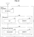
- FIG. 12 is a diagram illustrating an example of a hardware configuration of the user equipment according to the embodiment.
- FIG. 12 shows a configuration closer to an implementation example compared to FIG. 10 .
- the user equipment UE includes a RF (Radio Frequency) module 301 that executes a process related to a radio signal; a BB (Base Band) processing module 302 that performs baseband signal processing; and a UE control module 303 that performs a process of a higher layer, etc.
- RF Radio Frequency
- BB Base Band
- the RF module 301 generates a radio signal to be transmitted from an antenna by applying a D/A (Digital-to-Analog) conversion; modulation; a frequency conversion; power amplification, and so forth to a digital baseband signal received from the BB processing module 302. Additionally, a digital baseband signal is generated by applying a frequency conversion, an A/D (Analog to Digital) conversion, demodulation, and so forth to a received radio signal; and it is passed to the BB processing module 302.
- the RF module 301 include, for example, a part of the signal transmitter 101 and a part of the signal receiver 102, which are illustrated in FIG. 10 .
- the BB processing module 302 executes a process of mutually converting an IP packet and a digital baseband signal.
- a DSP (Digital Signal Processor) 312 is a processor that executes signal processing in the BB processing module 302.
- a memory 322 is used as a work area of the DSP 312.
- the BB processing module 302 includes, for example, a part of the signal transmitter 101, a part of the signal receiver 102, and the controller 105, which are illustrated in FIG. 10 .
- the UE control module 303 executes protocol processing of an IP layer, processing of various applications, and so forth.
- a processor 313 is the processor that executes a process to be executed by the UE control module 303.
- a memory 323 is used as a work area of the processor 313
- the UE control module 303 includes, for example, the retrieval unit 103 and the identifying unit 104, which are illustrated in FIG. 10 .
- FIG. 13 is a diagram illustrating an example of a hardware configuration of the base station according to the embodiment.
- FIG. 13 shows a configuration closer to an implementation example compared to FIG. 11 .
- the base station eNB includes a RF module 401 that executes a process related to a radio signal; a BB processing module 402 that performs baseband signal processing; a device control module 403 that performs a process of a higher layer, etc.; and a communication IF 404 that is an interface for connecting to a network.
- the RF module 401 generates a radio signal to be transmitted from an antenna by applying a D/A conversion; modulation; a frequency conversion; power amplification, and so forth to a digital baseband signal received from the BB processing module 402. Additionally, a digital baseband signal is generated by applying a frequency conversion, an A/D conversion, demodulation, and so forth to a received radio signal; and it is passed to the BB processing module 402.
- the RF module 401 includes, for example, a part of the signal transmitter 201 and a part of the signal receiver 202, which are illustrated in FIG. 11 .
- the BB processing module 402 executes a process of mutually converting an IP packet and a digital baseband signal.
- a DSP 412 is a processor that executes signal processing in the BB processing module 402.
- a memory 422 is used as a work area of the DSP 412.
- the BB processing module 402 includes, for example, a part of the signal transmitter 201, and a part of the signal receiver 202, which are illustrated in FIG. 11 .
- the device control module 403 executes protocol processing of an IP layer, OAM (Operation and Maintenance) processing, etc.
- a processor 413 is the processor that executes a process to be executed by the device control module 403.
- a memory 423 is used as a work area of the processor 413.
- the auxiliary storage device 433 is, for example, a HDD, etc., and stores various types of configuration information items, etc., for the base station eNB itself to operate.
- the device control module 403 includes, for example, the RRC controller 203, which is illustrated in FIG. 11 .
- user equipment for communicating with a base station in a radio communication system that supports narrow band communication
- the user equipment including a retrieval unit that retrieves, from the base station, information for identifying a second frequency band via a first frequency band, wherein a synchronization signal and broadcast information are transmitted on the first frequency band, and the synchronization signal and the broadcast information are not transmitted on the second frequency band; and an identifying unit that identifies a center frequency of the second frequency band based on the information.
- the information may include a bandwidth of a carrier including the first frequency band and the second frequency band; and information indicating a position of a frequency band in which the second frequency band is configured, among a plurality of frequency bands obtained by dividing the bandwidth of the carrier by a resource block length.
- the user equipment UE can specifically identify the center frequency of the additional PRB.
- the information may include a offset value between a center frequency of the first frequency band and the center frequency of the second frequency band.
- the information may include information indicating a bandwidth of the carrier in which the first frequency band and the second frequency band are configured; and the identifying unit may calculate a position of a frequency band in which the second frequency band is configured, among a plurality of frequency bands obtained by dividing the bandwidth of the carrier by a resource block length, using an identifier to be allocated to the user equipment. With this, the position of the additional PRB is distributed for each user equipment UE, so that the congestion of the additional PRB can be avoided.
- a controller may be included that performs timing alignment control or pathloss calculation using any one of a signal transmitted on the first frequency band and a signal transmitted on the second frequency band.
- the user equipment UE that communicates with the base station eNB using the anchor PRB or the additional PRB can perform the TA control or reporting of the PHR.
- a communication method executed by user equipment for communicating with a base station in a radio communication system that supports narrow band communication including a step of retrieving, from the base station, information for identifying a second frequency band via a first frequency band, wherein a synchronization signal and broadcast information are transmitted on the first frequency band, and the synchronization signal and the broadcast information are not transmitted on the second frequency band; and a step of identifying a center frequency of the second frequency band based on the information.
- each device the user equipment UE/the base station eNB described in the embodiment of the present disclosure may be a configuration that is implemented by executing a program by a CPU (processor) in the device including the CPU and a memory; may be a configuration that is implemented by hardware provided with a logic for the process described in the embodiment, such as a hardware circuit; or may be a mixture of programs and hardware.
- a CPU processor
- hardware provided with a logic for the process described in the embodiment, such as a hardware circuit
- a mixture of programs and hardware may be a mixture of programs and hardware.
- Reporting of the information is not limited to the aspect/embodiment described in this specification and may be executed by another method.
- reporting of information may be executed by physical layer signaling (e.g., DCI (Downlink Control Information), UCI (Uplink Control Information), higher layer signaling (e.g., RRC signaling, MAC signaling, and broadcast information (MIB (Master Information Block), SIB (System Information Block))), any other signals, or combination thereof.
- physical layer signaling e.g., DCI (Downlink Control Information), UCI (Uplink Control Information), higher layer signaling (e.g., RRC signaling, MAC signaling, and broadcast information (MIB (Master Information Block), SIB (System Information Block)
- MIB Master Information Block
- SIB System Information Block
- LTE Long Term Evolution
- LTE-A Long Term Evolution-Advanced
- SUPER 3G IMT-Advanced
- 4G 5G
- FRA Full Radio Access
- W-CDMA registered trademark
- GSM registered trademark
- CDMA 2000 UMB (Ultra Mobile Broadband)
- IEEE 802.11 Wi-Fi
- IEEE 802.16 WiMAX
- IEEE 802.20 UWB (Ultra-WideBand)
- Bluetooth registered trademark
- Determination or decision may be made by a value represented by one bit (0 or 1); may be made by a Boolean value (Boolean: true or false); or may be made by comparison of numerical values (e.g., comparison with a predetermined value).
- the channel and/or symbol may be a signal (signal).
- a signal may be a message.
- the UE may be referred to, by a person ordinarily skilled in the art, as a subscriber station, a mobile unit, a subscriber unit, a wireless unit, a remote unit, a mobile device, a wireless device, a wireless communication device, a remote device, a mobile subscriber station, an access terminal, a mobile terminal, a wireless terminal, a remote terminal, a handset, a user agent, a mobile client, a client, or some other suitable terms.
- determining (determining)” and “deciding (determining)” used in this specification may include various types of operations. For example, “determining” and “deciding” may include deeming that a result of calculating, computing, processing, deriving, investigating, looking up (e.g., search in a table, a database, or another data structure), or ascertaining is determined or decided. Furthermore, “determining” and “deciding” may include deeming that a result of receiving (e.g., reception of information), transmitting (e.g., transmission of information), input, output, or accessing (e.g., accessing data in memory) is determined or decided. Furthermore, “determining” and “deciding” may include deeming that a result of resolving, selecting, choosing, establishing, or comparing is determined or decided. Namely, “determining” and “deciding” may include deeming that some operation is determined or decided.
- processing procedures, sequences, etc., of each aspect/embodiment described in this specification may be exchanged as long as there is no inconsistency.
- the elements of the various steps are presented in an exemplary order and are not limited to a specific order presented.
- the information, etc., that is input or output may be stored in a specific location (e.g., a memory) and may be managed by a management table.
- the information, etc., that is input or output may be overwritten, updated, or added.
- the output information, etc. may be deleted.
- the input information, etc. may be transmitted to another device.
- Reporting of predetermined information is not limited to reporting that is explicitly executed, and may be executed implicitly (e.g., reporting of the predetermined information is not executed).
- Information, signals, etc., described in this specification may be represented using any of various other techniques.
- data, instructions, commands, information, signals, bits, symbols, chips, etc., described in the entire description may be represented by voltage, current, electromagnetic waves, magnetic fields or magnetic particles, optical fields or photons, or any combination thereof.
- Each of the software to be executed by the processor included in the UE in accordance with the embodiment of the present disclosure and the software to be executed by the processor included in the base station eNB may be stored in any appropriate storage medium, such as a random acess memory (RAM), a flash memory, a read-only memory (ROM), an EPROM, an EEPROM, a register, a hard disk drive (HDD), a removable disk, a CD-ROM, a database, a server, and so forth.
- RAM random acess memory
- ROM read-only memory
- EPROM an EPROM
- EEPROM electrically erasable programmable read-only memory
- register a register
- HDD hard disk drive
- CD-ROM compact disc-read only memory
- database a database
- server a server
- the anchor PRB is an example of the first frequency band.
- the additional PRB is an example of the second frequency band.
- the "operating band” and the “EARFCN of the DL carrier” is an example of "a center frequency of a carrier including the first frequency band and the second frequency band.”
- the "additional PRB index” is an example of "the information indicating the position of the frequency band in which the second frequency band is configured, among the plurality of frequency bands obtained by dividing the bandwidth of the carrier by the resource block length.”
- the “offset value from the center frequency of the anchor PRB" is an example of "the offset value between the center frequency of the first frequency band and the center frequency of the second frequency band.”
Landscapes
- Engineering & Computer Science (AREA)
- Signal Processing (AREA)
- Computer Networks & Wireless Communication (AREA)
- Mobile Radio Communication Systems (AREA)
Description
- The present invention relates to user equipment and a communication method.
- For a UMTS (Universal Mobile Telecommunications System) network, specifications of Long Term Evolution (LTE: Long Term Evolution) have been developed so as to achieve objects, such as higher data rate and lower latency (Non-Patent Document 1). Furthermore, in order to achieve objects of adopting a wider bandwidth and a higher data rate, successor systems of LTE (which are also referred to as LTE-A (LTE-Advanced), FRA (Future Radio Access), 4G, 5G, and so forth, for example) have been studied.
- Meanwhile, in recent years, with the reduction of the costs for the communication devices, technology of Machine-to-Machine communication (M2M: Machine-to-Machine) has been intensively developed, in which devices connected to a network automatically execute control by mutually communicating without human intervention. Especially, 3GPP (Third Generation Partnership Project) has advanced, among the M2M, standardization related to optimization of MTC (Machine Type Communication), as a cellular system for the Machine-to-Machine communication (Non-Patent Document 2). In the standardization activity, various types of functions have been studied which are to be adopted for a (MTC) terminal to be used for MTC; and, as an example, a MTC terminal has been studied for which a communication bandwidth is limited so as to reduce costs. As another example, since it is likely that a MTC terminal is to be installed in a location deep inside a building, or a location where it is difficult to perform radio communication due to large building entrance loss, such as underground, a MTC terminal has been studied, an object of which is to extend coverage. Based on the above two examples, terminals are classified into the following four patterns:
- 1. a terminal that is not provided with a coverage extension function, for which terminal there is no restriction on the communication bandwidth;
- 2. a terminal that is not provided with a coverage extension function, for which terminal there is a restriction on the communication bandwidth;
- 3. a terminal that is provided with a coverage extension function, for which terminal there is no restriction on the communication bandwidth; and
- 4. a terminal that is provided with a coverage extension function, for which terminal there is a restriction on the communication bandwidth.
- The MTC Terminal (MTC UE (User Equipment)) is considered to be used in a wide range of fields, such as electric meters, gas meters, vending machines, vehicles, and other industrial devices.
- Patent Document 1:
WO 2015/024858 A1 _[Non-Patent Document] - Non-Patent Document 1: 3GPP TS 36.300 "Evolved Universal Terrestrial Radio Access (E-UTRA) and Evolved Universal Terrestrial Radio Access Network (E-UTRAN); Overall description; "
- Non-Patent Document 2: 3GPP TS 36.888 "Study on provision of low-cost Machine-Type Communications (MTC) User Equipments (UEs) based on LTE (Release 12)"
- Non-Patent Document 3: 3GPP RP-151621 "New Work Item: NarrowBand IOT (NB-IOT)"
- Non-Patent Document 4: 3GPP TS 36.101 "User Equipment (UE) radio transmission and reception (Release 12)"
- Non-Patent Document 5: R2-160501 "Multiple carrier operation for NB-IoT" , published on 18 January 2016.
- Non-Patent Document 6: R1-160180 "Considerations of Multi-Band NB-IoT" , published on 17 January 2016.
- Non-Patent Document 7: R1-160121 "On NB-IoT anchor carrier", published on 12 January 2016.
- In
release 13 of 3GPP, as an example, a study related to a MTC terminal has been started that is for achieving further cost reduction by restricting a bandwidth to be used to be less than or equal to 180 kHz, which corresponds to a band width of 1 PRB (Physical Resource Block) (Non-Patent Document 3). The WI (Work Item) related to this study is referred to as NB-IoT (Narrow Band-Internet of Things). The NB-IoT aims to achieve coverage expansion that is greater than or equal to 20 dB compared to a usual GPRS (General Packet Radio Service) terminal, and that is greater than or equal to 20 dB compared to acategory 1 terminal specified in usual LTE. -
Patent Document 1 describes M2M communications. The UE acquires system information on the anchor carrier. The system information includes the number of subcarriers, information about an identity and a frequency location of each subcarriers. - Non-Patent
Document 5 describes multiple carrier operation for NB-IoT. It is proposed that a single so-called anchor NB-IoT carrier could be defined which carries the NB-PSS, NB-SSS, NB-PBCH and common control signaling such as paging and system information for all NB-IoT carriers of an LTE donor cell. - Non-Patent
Document 6 describes multi-Band NB-IoT. It is proposed that the NB-PSS/NB-SSS and NB-PBCH channels are conveyed by the anchor PRB only. The information of NB-IoT bands can be included by master/system information broadcast. - Non-Patent
Document 7 describes multi-Band NB-IoT, the anchor carrier carrying NB-PSS/NB-SSS/NB-PBCH/NB-SIB. The information on NB-IoT bands is indicated via RRC signalling. - There is a need for a technique that allows user equipment to obtain, in addition to information about a frequency band to be used as the starting point (the Anchor PRB), information about a frequency band to be additionally used (the Additional PRB).
- The invention is defined by the appended claims.
- According to the disclosed technology, a technique is provided that allows user equipment to obtain, in addition to the information about the frequency band to be used as the starting point (the Anchor PRB), the information about the frequency band to be additionally used (the Additional PRB).
-
-
FIG. 1 is a diagram illustrating an example of a configuration according to a method of allocating a bandwidth to be used in NB-IoT; -
FIG. 2A is a diagram illustrating an example of a carrier configuration when multiple carriers are to be used in the NB-IoT; -
FIG. 2B is a diagram illustrating an example of a carrier configuration when multiple carriers are to be used in the NB-IoT; -
FIG. 3 is a diagram for illustrating a problem; -
FIG. 4 is a diagram illustrating an example of a configuration of a radio communication system according to an embodiment; -
FIG. 5 is a sequence diagram illustrating an example of a processing procedure in the radio communication system according to the embodiment; -
FIG. 6 is a diagram for illustrating a method of reporting information about an additional carrier (version 1); -
FIG. 7 is a diagram for illustrating a method of reporting the information about the additional carrier (version 2); -
FIG. 8 is a diagram illustrating a method of reporting the information about the additional carrier (version 3); -
FIG. 9 is a diagram illustrating a case in which the additional carrier is configured in a guard band; -
FIG. 10 is a diagram illustrating an example of a functional configuration of user equipment according to the embodiment; -
FIG. 11 is a diagram illustrating an example of a functional configuration of a base station according to the embodiment; -
FIG. 12 is a diagram illustrating an example of a hardware configuration of the user equipment according to the embodiment; and -
FIG. 13 is a diagram illustrating an example of a hardware configuration of the base station according to the embodiment. - In the NB-IoT, three scenarios have been studied, as methods of allocating a bandwidth to be used. A first scenario is to configure the bandwidth to be used within a bandwidth that is actually available for communication (e.g., 9 MHz) in a LTE system bandwidth (e.g., 10 MHz) (a scenario using in-band); a second scenario is to configure the bandwidth to be used in a bandwidth corresponding to a guard band in the LTE system bandwidth (a scenario using a guard band); and a third scenario is to use a bandwidth dedicated for the NB-IoT.
FIG. 1 shows configuration examples of the bandwidth to be used in the first scenario and the second scenario. - Furthermore, in the NB-IoT, for the scenarios using the in-band and the guard band, a method has been studied which is for performing communication by configuring a plurality of bandwidths to be used. Specifically, for example, as illustrated in (1) of
FIG. 2 , a method has been studied such that synchronization signals (NB-PSS, NB-SSS) and broadcast information (NB-PBSH) are to be transmitted in each of a plurality of bandwidths to be used, so that user equipment can visit (camp on) any bandwidth to be used. - Additionally, as illustrated in (2) of
FIG. 2 , as another method, a method has been studied such that the synchronization signals (NB-PSS, NB-SSS) and the broadcast information (NB-PBCH) are to be transmitted only in a part of bandwidths to be used (which is referred to as "Anchor PRB (Anchor PRB), hereinafter) of the bandwidths to be used, and the synchronization signals and the broadcast information are not to be transmitted in the other bandwidths to be used (which is referred to as "Additional PRB (Additional PRB), hereinafter), so that a bandwidth to be used, which can be visited by user equipment, is to be restricted. In the method of (2) ofFIG. 2 , the user equipment belonging to the Anchor PRB is to transition to the Additional PRB to perform communication based on an indication, etc., from a base station eNB. - Here, in usual LTE, a resource position (a position of a resource block in a frequency direction, etc.) is determined using a center frequency of a system bandwidth as a reference. It follows that, if a center frequency of the Anchor PRB is the same as the center frequency of the system bandwidth, information about the Additional PRB (e.g., a center frequency and a frequency band) can be reported to user equipment UE simply by using the center frequency of the system bandwidth as the reference.
- However, as illustrated in
FIG. 3 , in NB-IoT, the center frequency of the Anchor PRB may not be equal to the center frequency of usual LTE. Namely, with the scheme of usual LTE, the information about the Additional PRB (e.g., the center frequency and the frequency band) may not be reported to the user equipment. - An embodiment is described below by referring to the drawings. Note that the embodiment described below is merely an example. For example, it is assumed that the radio communication system according to the embodiment is a system based on a scheme conforming to LTE; however, the present disclosure is not limited to LTE, and can be applied to another scheme. Note that, in the present specification and the claims, "LTE" is used in a broad meaning including, not only a communication scheme corresponding to release 8 or 9 of 3GPP, but also release 10, 11, 12, 13, or on or after
release 14, which corresponding to the fifth generation communication scheme, of 3GPP. - Furthermore, the base station and the user equipment according to the embodiment are described while assuming that they support the technology studied in the NB-IoT; however, the present disclosure is not limited to this, and can be applied to various communication schemes.
- In the following description, "PRB" is used while assuming that it implies "a bandwidth used in the NB-IoT (e.g., 180 kHz)" or "a carrier provided with a bandwidth used in the NB-IoT." However, the embodiment does not imply that the communication bandwidth is limited to 180 kHz. For example, it can be applied to a radio communication system for performing communication in a frequency band that is less than or equal to 180 kHz. Additionally, the anchor PRB may be referred to as an anchor carrier (Anchor Carrier); and the additional carrier may be referred to as an additional carrier (Additional Carrier).
-
FIG. 4 is a diagram illustrating a configuration example of the radio communication system according to the embodiment. As illustrated inFIG. 4 , the radio communication system according to the embodiment includes a base station eNB and user equipment UE. In the example ofFIG. 4 , one base station eNB and one unit of user equipment UE are depicted; however, a plurality of base stations eNBs may be provided and a plurality of units of user equipment UEs may be provided. - The base station eNB and the user equipment UE perform DL (Downlink) and UL (uplink) communication using an anchor PRB or an additional PRB. More specifically, the base station eNB transmits a synchronization signal and broadcast information with the anchor PRB. Furthermore, the user equipment UE detects the synchronization signal and the broadcast information transmitted through the anchor PRB by performing cell search; and the user equipment UE starts communication with the base station eNB through the anchor PRB by executing a random access procedure, etc.
- In the embodiment, the synchronization signal transmitted through the anchor PRB may be referred to as the NB-PSS (Narrow Band-Primary Synchronization Signal) or the NB-SSS (Narrow Band-Secondary Synchronization Signal); or may be referred to as the PSS or the SSS similar to usual LTE. Furthermore, a channel for transmitting the broadcast information through the anchor PRB may be referred to as the NB-PBCH (Narrow Band-Physical Broadcast Channel); or may be referred to as the PBCH similar to usual LTE.
- The base station eNB may be configured so as to support the communication scheme in the existing LTE; or may be configured so as to only support a function related to the NB-IoT. The user equipment UE may be referred to as a NB-IoT terminal; a MTC terminal; or user equipment UE with a limited frequency band to be supported.
- Next, a processing procedure performed by the wireless communication system according to the embodiment is described by using
FIG. 5 . In the embodiment, the user equipment UE performs communication with the base station eNB through the anchor PRB, and performs communication with the eNB by transitioning to the additional PRB according to an indication, etc., by the base station eNB. For that reason, it is required for the user equipment UE to store, in advance, information related to the additional PRB (e.g., the center frequency of the additional PRB) prior to transition from the anchor PRB to the additional PRB. Thus, in the embodiment, the base station eNB reports (S11), in advance, the information related to the additional PRB (which is referred to as "additional PRB information," hereinafter) to the user equipment UE through the anchor PRB. The base station eNB may report, to the user equipment UE, the additional PRB information using broadcast information (SIB) or an RRC message. More specifically, the broadcast information may be the SIB1 or the SIB2. Additionally, the RRC message may be, more specifically, RRC Connection Reconfiguration, RRC Connection Release, RRC Connection Setup, or RRC Connection Reestablishment. In response to a predetermined trigger (e.g., a command from the base station eNB, etc.), the user equipment UE switches a frequency of a RF (Radio Frequency) functional unit to transition from the anchor PRB to the additional PRB (S12), and performs communication with the base station eNB (S13). - Subsequently, a method is specifically described which is for transmitting information related to the additional PRB from the base station eNB to the user equipment UE in the processing procedure of step S11 of
FIG. 5 . - In the reporting method (version 1), the base station eNB reports, to the user equipment UE, "an operating band," "an EARFCN of a DL carrier," "a bandwidth of the DL carrier," and "an additional PRB index," as the additional PRB information. The user equipment UE identifies DL and UL center frequencies of the additional PRB using these information items. Furthermore, the user equipment UE determines that the UL bandwidth of the additional PRB is a predetermined bandwidth (e.g., 180 kHz).
- In the "operating band," information indicating a band of a LTE carrier is configured. For example, the E-UTRA Operation Band is configured, which is specified in Table 5.7.3-1, etc., of TS36.101 of 3GPP. Note that the LTE carrier means a carrier of usual LTE, which includes the anchor PRB and the additional PRB.
- In the "EARFCN of the DL carrier," an EARFCN (E-UTRA Absolute Radio Frequency Channel Number) of the DL carrier of the LTE carrier is configured.
- In the "bandwidth of the DL carrier," a bandwidth of the DL carrier of the LTE carrier (e.g., 5 MHz, 10 MHz, 20 MHz, etc.) is configured. Note that, in the "bandwidth of the DL carrier," a number of PRBs that form a bandwidth to be actually used for transmission (transmission bandwidth (Transmission Bandwidth)) may be configured.
- In the "additional PRB index," an index of a PRB in which an additional PRB is allocated is configured. Here, the index of the PRB means one of indexes added to a respective plurality of PRBs forming the bandwidth of the LTE carriers in a frequency direction in an order from zero. For example, in the LTE carrier illustrated in
FIG. 6 , in the system frequency band (10 MHz), a frequency band (9 MHz) that is available for actual transmission and reception is formed of 50 PRBs, so that indexes from 0 to 49 can be assigned to respective PRBs in this order. - A specific example of the method for the user equipment UE to identify the center frequency of the additional PRB is described below.
- First, the user equipment UE calculates the center frequency of the DL carrier using the "operating band" and the "EARFCN of the DL carrier." The method of calculating the center frequency of the DL carrier is specified, for example, in 5.7.3 of TS 36.101 (Non-Patent Document 4). Subsequently, the user equipment UE identifies the number of PRBs that exist in the bandwidth to be actually used for transmission in the DL carrier using the "bandwidth of the DL carrier," and identifies the index of the PRB corresponding to the center frequency of the DL carrier by assigning the indexes to respective PRBs in the frequency direction in the order from zero. In the example of
FIG. 6 , the PRB corresponding to the center frequency of the DL carrier is the PRB with theindex 24. - Subsequently, the user equipment UE calculates a difference between the index of the PRB corresponding to the center frequency of the DL carrier and the index that is configured as the "additional PRB index," and calculates the DL center frequency of the additional PRB using the calculated difference. In the example of
FIG. 6 , since the additional PRB index is 31, the DL center frequency of the additional PRB can be calculated to be the position that is separated from the center frequency of the DL carrier by "(31-24) × 180 kHz = 1260 kHz, (180 kHz is the bandwidth of 1 PRB)." Furthermore, the user equipment UE determines that the DL bandwidth of the additional PRB is the bandwidth of 1 PRB (180 kHz). - The user equipment UE can calculate the UL center frequency of the additional PRB by a similar procedure. As a specific example, the user equipment UE calculates the center frequency of the UL carrier using the "operating band" and the "EARFCN of the DL carrier." Once the "operating band" and the center frequency of the DL carrier are determined, the center frequency of the UL carrier can be uniquely determined in accordance with a default value that is predetermined in the standard specification. Specifically, it is specified in Table 5.7.4-1 of TS36.101. Note that, in the embodiment, the base station eNB may report, to the user equipment UE, the "EARFCN of the UL carrier," as the additional PRB information. Then, a case can be supported where the center frequency of the UL carrier is a value other than the default value specified in the standard specification.
- Subsequently, the user equipment UE identifies the number of PRBs that exist in the bandwidth that is actually used for transmission in the UL carrier while regarding that the "bandwidth of the DL carrier" is the bandwidth of the UL carrier; and identifies the index of the PRB corresponding to the center frequency of the UL carrier by assigning indexes to respective PRBs in the frequency direction in the order from zero. Note that, in the embodiment, the base station eNB may report, to the user equipment UE, the "bandwidth of the UL carrier," as the additional PRB information. Then, a case can be supported where the bandwidth of the UL carrier differs from the bandwidth of the DL carrier.
- Subsequently, the user equipment UE calculates a difference between the index of the PRB corresponding to the center frequency of the UL carrier and the index that is configured as the "additional PRB index," and calculates the UL center frequency of the additional PRB using the calculated difference. If the UL carrier has the configuration shown in
FIG. 6 , since the additional PRB index is 31, the UL center frequency of the additional PRB can be calculated to be the position that is separated from the center frequency of the UL carrier by "(31-24) × 180 kHz = 1260 kHz." - The base station eNB may separately report, to the user equipment UE, the "additional PRB index" corresponding to DL and the "additional PRB index" corresponding to UL, as the additional PRB information. Furthermore, the user equipment UE may calculate the DL and UL center frequencies of the additional PRB using the "additional PRB index" corresponding to DL and the "additional PRB index" corresponding to UL, respectively. In this manner, the base station eNB can configure the position of the additional PRB to be different positions for DL and UL.
- Furthermore, the base station eNB may additionally report, to the user equipment UE, the "anchor PRB index," as the additional PRB information. By receiving the "anchor PRB index," the user equipment UE can identify the index of the anchor PRB to which the own device belongs. Furthermore, the user equipment UE may calculate the center frequency of the additional PRB using a difference between the "anchor PRB index" and the index that is configured to be the "additional PRB index" and the DL/UL center frequencies of the anchor PRB to which the own device belongs. For example, in the example of
FIG. 6 , a difference of the indexes between the index (7) of the anchor PRB and the index (31) of the additional PRB is 24 PRBs, so that the user equipment UE can calculate that the DL/UL center frequencies of the additional PRB are positions that are separated from the DL/UL center frequencies of the anchor PRB by 4320 kHz (24 PRBs × 180 kHz), respectively. Note that, for the "anchor PRB index, the base station eNB may also separately report, to the user equipment UE, the "anchor PRB index" corresponding to DL and the "anchor PRB index" corresponding to the UL. Note that the user equipment UE can retrieve the DL/UL center frequencies of the anchor PRB to which the own device belongs from broadcast information, etc., transmitted on the anchor PRB. - When the anchor PRB or the additional PRB is to be configured in the guard band, the base station eNB may configure a bandwidth obtained by adding the bandwidth to be actually used for transmission and the bandwidth corresponding to the guard band to the "bandwidth of the DL carrier" (or the number of the PRBs forming the total bandwidth). The user equipment UE can identify the center frequency of the additional PRB configured in the guard band by a method that is the same as that of the above-described "specific example of the method of identifying the center frequency of the additional PRB."
- In the reporting method (version 2), the base station eNB reports, to the user equipment UE, "an offset value from the center frequency of the anchor PRB," which indicates a difference between the center frequency of the anchor PRB and the center frequency of the additional PRB, as the additional PRB information. The user equipment UE identifies DL and UL center frequencies of the additional PRB using the center frequency of the identified anchor PRB and the "offset value from the center frequency of the anchor PRB." Furthermore, the user equipment UE determines that the UL bandwidth of the additional PRB is a predetermined bandwidth (e.g., 180 kHz). Note that the user equipment UE can obtain the DL/UL center frequencies of the anchor PRB to which the own device belongs from broadcast information, etc., transmitted on the anchor PRB.
- The "offset value from the center frequency of the anchor PRB" may be represented by an integral multiple of the bandwidth per 1 PRB (180 kHz). For example, when the anchor PRB and the additional PRB are configured at positions shown in
FIG. 7 , the "offset value from the center frequency of the anchor PRB" is set to "+ 24." - Furthermore, the "offset value from the center frequency of the anchor PRB" may be represented by an integral multiple of 100 kHz. For performing a cell search, the user equipment UE often performs the search at 100 kHz intervals. Consequently, by representing the "offset value from the center frequency of the anchor PRB" by the integral multiple of 100 kHz, the user equipment UE can quickly adjust the frequency setting of the RF functional unit to the frequency of the additional PRB. Note that, in this case, it is assumed that the position of the additional PRB may be allowed not to match the position of the PRB of the LTE carrier.
- Furthermore, the base station eNB may report, to the user equipment UE, the "anchor PRB index" and the "additional PRB index" described in the reporting method (version 1), instead of the "offset value from the center frequency of the anchor PRB," and the user equipment UE may calculate the offset value for itself.
- Note that the user equipment UE may determine that the "offset value from the center frequency of the anchor PRB" is an offset value that is common between DL and UL. Furthermore, the base station eNB may separately report, to the user equipment UE, the "offset value from the center frequency of the anchor PRB" corresponding to DL and the "offset value from the center frequency of the anchor PRB" corresponding to the UL.
- In the reporting method (version 1), the center frequency of the additional PRB is identified using the position of the physical PRB; however, in the modified example of the reporting method (version 1), logical indexes are used, as the indexes identifying the anchor PRB and the additional PRB.
- More specifically, information for uniquely associating indexes of PRBs (PRB indexes) forming a frequency band available for actual transmission and reception in the UL/DL system frequency band with logical indexes to be assigned to PRBs to be candidates of the anchor PRB and the additional PRB (which are referred to as the "VRB index," hereinafter) is retained, in advance, between the base station eNB and the user equipment UE.
- More specifically, for example, as illustrated in
FIG. 8 , the PRBs with the indexes "7," "10," "15," "25," "31," "40," and "46" are associated, in advance, with the VRB indexes "0" through "6," respectively. - The PRB indexes and the VRB indexes may be associated in common between DL and UL; or may be independently associated between DL and UL. Furthermore, the VRB index "0" may be associated with the index of the PRB corresponding to the anchor PRB.
- The base station eNB reports, to the user equipment UE, the "operating band," the "EARFCN of the DL carrier," the "bandwidth of the DL carrier," and the "additional PRB index," as the additional PRB information. Furthermore, for the "additional PRB index," a VRB index is configured.
- The user equipment UE identifies the PRB index corresponding to the VRB index configured for the "additional PRB index" using the information for uniquely associating the PRB indexes with the VRB indexes; and identifies the center frequency of the additional PRB by the method similar to that of the "specific example of the method of identifying the center frequency of the additional PRB" described in the reporting method (version 1).
- Note that, in the modified example of the reporting method (version 1), for each user equipment UE, the additional PRB may be distributed. Specifically, the base station eNB may transmit the additional PRB information to the user equipment UE without enclosing the "additional PRB index," and the user equipment UE may calculate the VRB index of the additional PRB by substituting its own UE ID in a predetermined calculation formula. For example, the user equipment UE may calculate the VRB index of the additional PRB allocated to itself using a calculation formula, "VRB index = UE_ID mode the number of VRBs that are candidates of the additional PRB." For example, the UE_ID may be a RNTI (Radio Network Temporary Identity), an IMSI (International Mobile Subscriber Identity), a S-TMSI (SAE-Temporary Mobile Subscriber Identify), etc. For example, in
FIG. 8 , the number of the VRBs to be candidates of the additional PRB are 6 VRBs from "1" to "6," and each user equipment UE can identify, by the above-described calculation formula, one of the PRBs corresponding to the VRB indexes "1" through "6," as the additional PRB. In this manner, the additional RPB to be allocated to each user equipment UE is to be distributed, and the congestion of the additional PRBs can be avoided. - In the reporting method (version 2), the information for uniquely associating the PRB indexes with the VRB indexes is retained, in advance, between the user equipment UE and the base station eNB, and the "offset value from the center frequency of the anchor PRB" may be represented as a difference of VRB indexes. For example, in
FIG. 8 , when the anchor PRB is configured at the position with the VRB index "0" and the additional PRB is configured at the position with the VRB index "4," the "offset value from the center frequency of the anchor PRB" may be set to + 4 VRBs. Note that, in this case, it may be fixedly specified that the VRB index of the anchor PRB is "0," or the VRB index of the anchor PRB may be reported from the base station eNB to the user equipment UE. - Furthermore, in the reporting method (version 2), the additional PRB may also be distributed for each user equipment UE. For example, the base station eNB may report only the VRB index of the anchor PRB, as the additional PRB information; and the user equipment UE may calculate the VRB index of the additional PRB by substituting its own UEID in a predetermined calculation formula. The user equipment UE can calculate the actual offset value (the number of the PRBs) using information for uniquely associating the PRB indexes with the VRB indexes, the VRB index of the anchor PRB reported from the base station eNB, and the calculated VRB index of the additional PRB.
- In the embodiment, when the additional PRB is not configured, the user equipment UE communicates with the base station eNB through the anchor PRB; and when the additional PRB is configured by the additional PRB information, the user equipment UE communicates with the base station eNB through one of the anchor PRB and the additional PRB.
- Consequently, as the DL PRB to be referred to for performing the UL TA (Timing Alignment) control, the user equipment UE may always use the anchor PRB regardless of whether the additional PRB is configured; or may use the additional PRB when the additional PRB is configured. Furthermore, when the additional PRB is configured, it can be indicated (configured) from the base station eNB to the user equipment UE as to whether the anchor PRB is to be used or the additional PRB is to be used, as the DL PRB to be referred to for performing the TA control.
- Similarly, as the DL PRB to be referred to for calculating the pathloss (Pathloss) for reporting the PHR (Power Head Room) to the base station eNB, the user equipment UE may always use the anchor PRB regardless of presence or absence of the configuration of the additional PRB; or when the additional PRB is configured, the additional PRB may be used. Furthermore, when the additional PRB is configured, it can be indicated (configured) from the base station eNB to the user equipment UE as to whether the anchor PRB is to be used or the additional PRB is to be used, as the DL PRB to be referred to for calculating the pathloss.
- In the embodiment, when the additional PRB is configured in the guard band (e.g., the case where the additional PRB is configured in the resource shown in
FIG. 9 ), the signal mapping at the physical layer in the additional PRB may be a new configuration optimized for signal transmission with 1 PRB, or may be a configuration similar to that of usual LTE. Furthermore, the base station eNB may report (set), to the user equipment, whether the signal mapping at the physical layer in the additional PRB is to be the new configuration or the configuration that is the same as that of usual LTE. - When the new configuration is to be adopted, the base station eNB may apply the CRS configuration and the channel configuration of the PDCCH, which are optimized for signal transmission with 1 PRB, to the additional PRB so as to transmit signals of the PDCCH (NB-PDCCH), the PDSCH (NB-PDSCH), and various types of RSs (NB-RSs).
- When the configuration that is the same as that of usual LTE is to be adopted and a DL signal is to be received on the additional PRB, the user equipment UE may regard that the CRS configuration and the channel configuration of the PDCCH are applied, which are the same as those of usual LTE, so as to perform a process, such as rate matching.
- Examples of functional configurations of the user equipment UE and the base station eNB are described, which execute the above-described processing procedures. However, a part of the above-described processes of the user equipment UE and the base station eNB (e.g., only one or more specific embodiments, etc.) may be executable.
-
FIG. 10 is a diagram illustrating an example of a functional configuration of the user equipment according to the embodiment. As illustrated inFIG. 10 , the user equipment UE includes asignal transmitter 101; asignal receiver 102; aretrieval unit 103; an identifyingunit 104; and acontroller 105.FIG. 10 only shows, in the user equipment UE, the functional units that are particularly related to the embodiment , and it includes, at least, a function, which is not depicted, for performing an operation conforming to the LTE. Furthermore, the functional configuration depicted inFIG. 10 is merely an example. The functional division and the names of the functional units may be any division and names, provided that the operation according to the embodiment can be performed. - The
signal transmitter 101 is provided with a function for generating various types of signals to be transmitted from the user equipment UE, and for wirelessly transmitting them. Thesignal receiver 102 is provided with a function for receiving various types of radio signals from the base station eNB. Each of thesignal transmitter 101 and thesignal receiver 102 is provided with a packet buffer, and it is assumed that each of thesignal transmitter 101 and thesignal receiver 102 performs the processes of the layer 1 (PHY), the layer 2 (MAC, RLC, PDCP), and the layer 3 (RRC) (however, the processes are not limited to these). Furthermore, thesignal transmitter 101 and thesignal receiver 102 are provided with functions for transmitting and receiving various types of radio signals through the additional PRB by changing the frequency of the RF functional unit based on the center frequency of the additional PRB identified by the identifyingunit 104. - The
retrieval unit 103 is provided with a function for retrieving, from the base station eNB, the additional PRB information through the anchor PRB. - The identifying
unit 104 is provided with a function for identifying the center frequency of the additional PRB based on the additional PRB information. Furthermore, when a VRB index is configured in the additional PRB information, as the information indicating the position of the frequency band at which the additional PRB is configured, the identifyingunit 104 may identify the position (PRB index) of the frequency band at which the additional PRB is configured based on the information for uniquely associating the PRB indexes with the VRB indexes, which is stored in a memory, etc., in advance. - Furthermore, the identifying
unit 104 may identify the position (PRB index) of the frequency band at which the additional PRB is configured using the UE_ID of the user equipment UE itself and the predetermined calculation formula. - The
controller 105 is provided with a function for performing the TA control or for calculating the pathloss using any one of a DL signal transmitted on the anchor PRB or a DL signal transmitted on the additional PRB. -
FIG. 11 is a diagram illustrating an example of a functional configuration of the base station according to the embodiment. As illustrated inFIG. 11 , the base station eNB includes asignal transmitter 201; asignal receiver 202; and aRRC controller 203.FIG. 11 only shows, in the base station eNB, the functional units that are particularly related to the embodiment, and it includes, at least, a function, which is not depicted, for performing an operation conforming to the LTE. Furthermore, the functional configuration depicted inFIG. 11 is merely an example. The functional division and the names of the functional units may be any division and names, provided that the operation according to the embodiment can be performed. - The
signal transmitter 201 is provided with a function for generating various types of signals to be transmitted from the base station eNB, and for wirelessly transmitting them. Thesignal receiver 202 is provided with a function for wirelessly receiving various types of signals from the user equipment UE, and for retrieving higher layer signals from the received physical layer signals. Each of thesignal transmitter 201 and thesignal receiver 202 is provided with a packet buffer, and it is assumed that each of thesignal transmitter 201 and thesignal receiver 202 performs the processes of the layer 1 (PHY), the layer 2 (MAC, RLC, PDCP), and the layer 3 (RRC) (however, the processes are not limited to these). Furthermore, thesignal transmitter 201 and thesignal receiver 202 are provided with functions for communicating with the user equipment UE using the anchor PRB and the additional PRB. - The
RRC controller 203 is provided with a function for reporting (configuring) additional PRB information to the user equipment UE using broadcast information or a RRC message. - Each of the above-described functional configurations of the user equipment UE and the base station eNB may be entirely implemented by a hardware circuit (e.g., one or more IC chips); or a part of it may be formed of a hardware circuit and the other part may be implemented by a CPU and a program.
-
FIG. 12 is a diagram illustrating an example of a hardware configuration of the user equipment according to the embodiment.FIG. 12 shows a configuration closer to an implementation example compared toFIG. 10 . As illustrated inFIG. 12 , the user equipment UE includes a RF (Radio Frequency)module 301 that executes a process related to a radio signal; a BB (Base Band)processing module 302 that performs baseband signal processing; and aUE control module 303 that performs a process of a higher layer, etc. - The
RF module 301 generates a radio signal to be transmitted from an antenna by applying a D/A (Digital-to-Analog) conversion; modulation; a frequency conversion; power amplification, and so forth to a digital baseband signal received from theBB processing module 302. Additionally, a digital baseband signal is generated by applying a frequency conversion, an A/D (Analog to Digital) conversion, demodulation, and so forth to a received radio signal; and it is passed to theBB processing module 302. TheRF module 301 include, for example, a part of thesignal transmitter 101 and a part of thesignal receiver 102, which are illustrated inFIG. 10 . - The
BB processing module 302 executes a process of mutually converting an IP packet and a digital baseband signal. A DSP (Digital Signal Processor) 312 is a processor that executes signal processing in theBB processing module 302. Amemory 322 is used as a work area of theDSP 312. TheBB processing module 302 includes, for example, a part of thesignal transmitter 101, a part of thesignal receiver 102, and thecontroller 105, which are illustrated inFIG. 10 . - The
UE control module 303 executes protocol processing of an IP layer, processing of various applications, and so forth. Aprocessor 313 is the processor that executes a process to be executed by theUE control module 303. Amemory 323 is used as a work area of theprocessor 313 TheUE control module 303 includes, for example, theretrieval unit 103 and the identifyingunit 104, which are illustrated inFIG. 10 . -
FIG. 13 is a diagram illustrating an example of a hardware configuration of the base station according to the embodiment.FIG. 13 shows a configuration closer to an implementation example compared toFIG. 11 . As illustrated inFIG. 13 , the base station eNB includes aRF module 401 that executes a process related to a radio signal; aBB processing module 402 that performs baseband signal processing; adevice control module 403 that performs a process of a higher layer, etc.; and a communication IF 404 that is an interface for connecting to a network. - The
RF module 401 generates a radio signal to be transmitted from an antenna by applying a D/A conversion; modulation; a frequency conversion; power amplification, and so forth to a digital baseband signal received from theBB processing module 402. Additionally, a digital baseband signal is generated by applying a frequency conversion, an A/D conversion, demodulation, and so forth to a received radio signal; and it is passed to theBB processing module 402. TheRF module 401 includes, for example, a part of thesignal transmitter 201 and a part of thesignal receiver 202, which are illustrated inFIG. 11 . - The
BB processing module 402 executes a process of mutually converting an IP packet and a digital baseband signal. ADSP 412 is a processor that executes signal processing in theBB processing module 402. Amemory 422 is used as a work area of theDSP 412. TheBB processing module 402 includes, for example, a part of thesignal transmitter 201, and a part of thesignal receiver 202, which are illustrated inFIG. 11 . - The
device control module 403 executes protocol processing of an IP layer, OAM (Operation and Maintenance) processing, etc. Aprocessor 413 is the processor that executes a process to be executed by thedevice control module 403. Amemory 423 is used as a work area of theprocessor 413. Theauxiliary storage device 433 is, for example, a HDD, etc., and stores various types of configuration information items, etc., for the base station eNB itself to operate. Thedevice control module 403 includes, for example, theRRC controller 203, which is illustrated inFIG. 11 . - As described above, according to the embodiment, there is provided user equipment for communicating with a base station in a radio communication system that supports narrow band communication, the user equipment including a retrieval unit that retrieves, from the base station, information for identifying a second frequency band via a first frequency band, wherein a synchronization signal and broadcast information are transmitted on the first frequency band, and the synchronization signal and the broadcast information are not transmitted on the second frequency band; and an identifying unit that identifies a center frequency of the second frequency band based on the information. With this, a technique is provided that allows user equipment to obtain, in addition to the information about the frequency band to be used as the starting point (the anchor PRB), the information about the frequency band to be additionally used (the additional PRB).
- Furthermore, the information may include a bandwidth of a carrier including the first frequency band and the second frequency band; and information indicating a position of a frequency band in which the second frequency band is configured, among a plurality of frequency bands obtained by dividing the bandwidth of the carrier by a resource block length. With this, the user equipment UE can specifically identify the center frequency of the additional PRB.
- Furthermore, the information may include a offset value between a center frequency of the first frequency band and the center frequency of the second frequency band. With this, the user equipment UE can specifically identify the center frequency of the additional PRB.
- Furthermore, the information may include information indicating a bandwidth of the carrier in which the first frequency band and the second frequency band are configured; and the identifying unit may calculate a position of a frequency band in which the second frequency band is configured, among a plurality of frequency bands obtained by dividing the bandwidth of the carrier by a resource block length, using an identifier to be allocated to the user equipment. With this, the position of the additional PRB is distributed for each user equipment UE, so that the congestion of the additional PRB can be avoided.
- Furthermore, a controller may be included that performs timing alignment control or pathloss calculation using any one of a signal transmitted on the first frequency band and a signal transmitted on the second frequency band. With this, the user equipment UE that communicates with the base station eNB using the anchor PRB or the additional PRB can perform the TA control or reporting of the PHR.
- Furthermore, according to the embodiment, there is provided a communication method executed by user equipment for communicating with a base station in a radio communication system that supports narrow band communication, the communication method including a step of retrieving, from the base station, information for identifying a second frequency band via a first frequency band, wherein a synchronization signal and broadcast information are transmitted on the first frequency band, and the synchronization signal and the broadcast information are not transmitted on the second frequency band; and a step of identifying a center frequency of the second frequency band based on the information. With this, a technique is provided that allows user equipment to obtain, in addition to the information about the frequency band to be used as the starting point (the anchor PRB), the information about the frequency band to be additionally used (the additional PRB).
- The configuration of each device (the user equipment UE/the base station eNB) described in the embodiment of the present disclosure may be a configuration that is implemented by executing a program by a CPU (processor) in the device including the CPU and a memory; may be a configuration that is implemented by hardware provided with a logic for the process described in the embodiment, such as a hardware circuit; or may be a mixture of programs and hardware.
- Reporting of the information is not limited to the aspect/embodiment described in this specification and may be executed by another method. For example, reporting of information may be executed by physical layer signaling (e.g., DCI (Downlink Control Information), UCI (Uplink Control Information), higher layer signaling (e.g., RRC signaling, MAC signaling, and broadcast information (MIB (Master Information Block), SIB (System Information Block))), any other signals, or combination thereof.
- The aspect/embodiment described in this specification may be applied to LTE (Long Term Evolution), LTE-A (LTE-Advanced), SUPER 3G, IMT-Advanced, 4G, 5G, FRA (Future Radio Access), W-CDMA (registered trademark), GSM (registered trademark), CDMA 2000, UMB (Ultra Mobile Broadband), IEEE 802.11 (Wi-Fi), IEEE 802.16 (WiMAX), IEEE 802.20, UWB (Ultra-WideBand), Bluetooth (registered trademark), a system utilizing any other suitable system, and/or a next generation system extended based on these.
- Determination or decision may be made by a value represented by one bit (0 or 1); may be made by a Boolean value (Boolean: true or false); or may be made by comparison of numerical values (e.g., comparison with a predetermined value).
- Note that the terms described in this specification and/or the terms required for understanding of this specification may be replaced with terms having the same or similar meaning. For example, the channel and/or symbol may be a signal (signal). Further, a signal may be a message.
- The UE may be referred to, by a person ordinarily skilled in the art, as a subscriber station, a mobile unit, a subscriber unit, a wireless unit, a remote unit, a mobile device, a wireless device, a wireless communication device, a remote device, a mobile subscriber station, an access terminal, a mobile terminal, a wireless terminal, a remote terminal, a handset, a user agent, a mobile client, a client, or some other suitable terms.
- The terms "determining (determining)" and "deciding (determining)" used in this specification may include various types of operations. For example, "determining" and "deciding" may include deeming that a result of calculating, computing, processing, deriving, investigating, looking up (e.g., search in a table, a database, or another data structure), or ascertaining is determined or decided. Furthermore, "determining" and "deciding" may include deeming that a result of receiving (e.g., reception of information), transmitting (e.g., transmission of information), input, output, or accessing (e.g., accessing data in memory) is determined or decided. Furthermore, "determining" and "deciding" may include deeming that a result of resolving, selecting, choosing, establishing, or comparing is determined or decided. Namely, "determining" and "deciding" may include deeming that some operation is determined or decided.
- The expression "based on" used in the present specification does not mean "based only on" unless otherwise stated particularly. In other words, the expression "based on" means both "based only on" and "based at least on."
- Furthermore, processing procedures, sequences, etc., of each aspect/embodiment described in this specification may be exchanged as long as there is no inconsistency. For example, for the methods described in the specification, the elements of the various steps are presented in an exemplary order and are not limited to a specific order presented.
- The information, etc., that is input or output may be stored in a specific location (e.g., a memory) and may be managed by a management table. The information, etc., that is input or output may be overwritten, updated, or added. The output information, etc., may be deleted. The input information, etc., may be transmitted to another device.
- Reporting of predetermined information (e.g., reporting of "being X") is not limited to reporting that is explicitly executed, and may be executed implicitly (e.g., reporting of the predetermined information is not executed).
- Information, signals, etc., described in this specification may be represented using any of various other techniques. For example, data, instructions, commands, information, signals, bits, symbols, chips, etc., described in the entire description may be represented by voltage, current, electromagnetic waves, magnetic fields or magnetic particles, optical fields or photons, or any combination thereof.
- The invention is defined by the appended claims. Specific examples of numerical values are used in the description in order to facilitate understanding of the invention. However, these numerical values are merely an example, and any other appropriate values may be used, except as indicated otherwise. The separations of the items in the above description are merely an example. Depending on necssity, subject matter described in two or more items may be combined and used, and subject matter described in an item may be applied to subject matter described in another item (provided that they do not contradict). A boundary of a functional unit or a processor in the functional block diagrams may not necessarily correspond to a boundary of a physical component. An operation by a plurality of functional units may be physically executed by a single component, or an operation of a single functional unit may be physically executed by a plurality of components. The order of each of the sequences and flow charts described in the embodiment may be re-arranged, provided that they do not contradict. For the convenience of description, the user equipment UE/ the base station eNB are described by using the functional block diagrams; however, such devices may be implemented in hardware, software, or combinations thereof. Each of the software to be executed by the processor included in the UE in accordance with the embodiment of the present disclosure and the software to be executed by the processor included in the base station eNB may be stored in any appropriate storage medium, such as a random acess memory (RAM), a flash memory, a read-only memory (ROM), an EPROM, an EEPROM, a register, a hard disk drive (HDD), a removable disk, a CD-ROM, a database, a server, and so forth.
- Note that, in the embodiment, the anchor PRB is an example of the first frequency band. The additional PRB is an example of the second frequency band. The "operating band" and the "EARFCN of the DL carrier" is an example of "a center frequency of a carrier including the first frequency band and the second frequency band." The "additional PRB index" is an example of "the information indicating the position of the frequency band in which the second frequency band is configured, among the plurality of frequency bands obtained by dividing the bandwidth of the carrier by the resource block length." The "offset value from the center frequency of the anchor PRB" is an example of "the offset value between the center frequency of the first frequency band and the center frequency of the second frequency band."
- This international patent application is based upon and claims the benefit of priority of Japanese Patent Application No.
2016-020331 filed on February 4, 2016 -
- UE: user equipment
- eNB: base station
- 101: signal transmitter
- 102: signal receiver
- 103: retrieval unit
- 104: identifying unit
- 105: controller
- 201: signal transmitter
- 202: signal receiver
- 203: RRC controller
- 301: RF module
- 302: BB processing module
- 303: UE control module
- 401: RF module
- 402: BB processing module
- 403: device control module
- 404: communication IF
Claims (5)
- User equipment adapted to communicate with a base station in a radio communication system that supports narrow band communication, the user equipment comprising:a retrieval unit (103) adapted to retrieve, from the base station, information for identifying a second frequency band via a first frequency band, wherein a synchronization signal and broadcast information are transmitted on the first frequency band, and the synchronization signal and the broadcast information are not transmitted on the second frequency band;a controller (105) adapted to perform timing alignment control using a signal transmitted on the first frequency band regardless of whether the second frequency band is configured; andan identifying unit (104) adapted to identify a center frequency of the second frequency band based on the information retrieved by the retrieval unit, whereinthe information is reported to the user equipment using an RRC Connection Setup message or a RRC connection Reestablishment message.
- The user equipment according to claim 1, wherein the information includes a bandwidth of a carrier including the first frequency band and the second frequency band, and information indicating a position of a frequency band in which the second frequency band is configured, among a plurality of frequency bands obtained by dividing the bandwidth of the carrier by a resource block length.
- The user equipment according to claim 1, wherein the information includes a offset value between a center frequency of the first frequency band and the center frequency of the second frequency band.
- The user equipment according to claim 1, wherein the information includes information that indicates a bandwidth of a carrier in which the first frequency band and the second frequency band are configured, and
wherein the identifying unit (104) is adapted to calculate a position of a frequency band in which the second frequency band is configured, among a plurality of frequency bands obtained by dividing the bandwidth of the carrier by a resource block length, using an identifier allocated to the user equipment. - A communication method executed by user equipment for communicating with a base station in a radio communication system that supports narrow band communication, the communication method comprising:a step of retrieving (S11), from the base station, information for identifying a second frequency band via a first frequency band, wherein a synchronization signal and broadcast information are transmitted on the first frequency band, and the synchronization signal and the broadcast information are not transmitted on the second frequency band;a step of identifying (S12) a center frequency of the second frequency band based on the retrieved information; anda step of erforming timing alignment control using a signal transmitted on the first frequency band regardless of whether the second frequency band is configured, whereinthe information is reported to the user equipment using an RRC Connection Setup message or a RRC connection Reestablishment message.
Applications Claiming Priority (2)
| Application Number | Priority Date | Filing Date | Title |
|---|---|---|---|
| JP2016020331A JP6174735B1 (en) | 2016-02-04 | 2016-02-04 | User device and communication method |
| PCT/JP2017/003559 WO2017135287A1 (en) | 2016-02-04 | 2017-02-01 | User device and communication method |
Publications (3)
| Publication Number | Publication Date |
|---|---|
| EP3413629A1 EP3413629A1 (en) | 2018-12-12 |
| EP3413629A4 EP3413629A4 (en) | 2019-03-13 |
| EP3413629B1 true EP3413629B1 (en) | 2021-06-23 |
Family
ID=59499674
Family Applications (1)
| Application Number | Title | Priority Date | Filing Date |
|---|---|---|---|
| EP17747443.4A Active EP3413629B1 (en) | 2016-02-04 | 2017-02-01 | User device and communication method |
Country Status (8)
| Country | Link |
|---|---|
| US (1) | US11071108B2 (en) |
| EP (1) | EP3413629B1 (en) |
| JP (1) | JP6174735B1 (en) |
| CN (1) | CN107925851B (en) |
| CA (1) | CA2993140A1 (en) |
| CO (1) | CO2018007120A2 (en) |
| ES (1) | ES2880374T3 (en) |
| WO (1) | WO2017135287A1 (en) |
Families Citing this family (7)
| Publication number | Priority date | Publication date | Assignee | Title |
|---|---|---|---|---|
| US10477537B2 (en) | 2016-02-11 | 2019-11-12 | Qualcomm Incorporated | Multi-PRB operation for narrowband systems |
| CN108289332B (en) * | 2017-01-09 | 2024-05-10 | 夏普株式会社 | Frequency position indication method of wireless signal, base station and user equipment |
| US11178012B2 (en) * | 2017-09-06 | 2021-11-16 | Apple Inc. | Configuration schemes for secondary cell, bandwidth part and physical resource block indexing |
| CN110138534B (en) * | 2017-09-08 | 2020-12-08 | 华为技术有限公司 | Signal sending method and device and readable storage medium |
| US10707915B2 (en) * | 2017-12-04 | 2020-07-07 | Qualcomm Incorporated | Narrowband frequency hopping mechanisms to overcome bandwidth restrictions in the unlicensed frequency spectrum |
| US11546904B2 (en) * | 2018-04-06 | 2023-01-03 | Telefonaktiebolaget Lm Ericsson (Publ) | Methods and apparatuses for at least reducing an image interference for uplink transmission |
| US20220346170A1 (en) * | 2019-02-25 | 2022-10-27 | Ntt Docomo, Inc. | User equipment and communication method |
Family Cites Families (11)
| Publication number | Priority date | Publication date | Assignee | Title |
|---|---|---|---|---|
| US7158810B2 (en) * | 2002-06-27 | 2007-01-02 | Nokia Corporation | Indication of user equipment capabilities before radio resource control connection |
| JP5190233B2 (en) * | 2006-09-01 | 2013-04-24 | パナソニック株式会社 | Wireless communication device |
| JP2009071560A (en) * | 2007-09-13 | 2009-04-02 | Hitachi Ltd | Video equipment |
| US8780860B2 (en) * | 2010-05-01 | 2014-07-15 | Pantech Co., Ltd. | Apparatus and method for transmitting sounding reference signal in wireless communication system supporting multiple component carriers |
| US9629156B2 (en) * | 2011-08-12 | 2017-04-18 | Telefonaktiebolaget Lm Ericsson (Publ) | Aggregated carrier synchronization and reference signal transmitting and receiving methods, devices and systems |
| EP3043610B1 (en) * | 2013-09-27 | 2019-09-04 | Huawei Technologies Co., Ltd. | Communication method, user equipment and base station |
| WO2015188848A1 (en) * | 2014-06-10 | 2015-12-17 | Nokia Solutions And Networks Oy | Multiplexing communications in wireless systems |
| EP3567792B1 (en) * | 2015-07-22 | 2020-09-09 | Samsung Electronics Co., Ltd. | Method and device for operating machine type device in wireless communication system |
| US11212760B2 (en) * | 2015-09-24 | 2021-12-28 | Qualcomm Incorporated | Common synchronization channel design for narrowband communications |
| CN106921468B (en) * | 2015-12-28 | 2020-05-22 | 中兴通讯股份有限公司 | Information transmission method and device |
| EP3410662A4 (en) * | 2016-01-27 | 2019-09-25 | NTT DoCoMo, Inc. | User terminal, wireless base station, and wireless communication method |
-
2016
- 2016-02-04 JP JP2016020331A patent/JP6174735B1/en active Active
-
2017
- 2017-02-01 CN CN201780002841.8A patent/CN107925851B/en active Active
- 2017-02-01 CA CA2993140A patent/CA2993140A1/en not_active Abandoned
- 2017-02-01 EP EP17747443.4A patent/EP3413629B1/en active Active
- 2017-02-01 WO PCT/JP2017/003559 patent/WO2017135287A1/en unknown
- 2017-02-01 ES ES17747443T patent/ES2880374T3/en active Active
-
2018
- 2018-02-15 US US15/897,495 patent/US11071108B2/en active Active
- 2018-07-09 CO CONC2018/0007120A patent/CO2018007120A2/en unknown
Non-Patent Citations (1)
| Title |
|---|
| LENOVO: "On NB-IoT anchor carrier", vol. RAN WG1, no. Budapest, HU; 20160118 - 20160120, 12 January 2016 (2016-01-12), XP051064733, Retrieved from the Internet <URL:http://www.3gpp.org/ftp/tsg_ran/WG1_RL1/TSGR1_AH/LTE_NB-IoT_1601/Docs/> [retrieved on 20160112] * |
Also Published As
| Publication number | Publication date |
|---|---|
| JP6174735B1 (en) | 2017-08-02 |
| ES2880374T3 (en) | 2021-11-24 |
| CN107925851B (en) | 2021-03-05 |
| US20180176919A1 (en) | 2018-06-21 |
| US11071108B2 (en) | 2021-07-20 |
| CO2018007120A2 (en) | 2018-07-19 |
| CA2993140A1 (en) | 2017-08-10 |
| EP3413629A4 (en) | 2019-03-13 |
| EP3413629A1 (en) | 2018-12-12 |
| CN107925851A (en) | 2018-04-17 |
| WO2017135287A1 (en) | 2017-08-10 |
| JP2017139675A (en) | 2017-08-10 |
Similar Documents
| Publication | Publication Date | Title |
|---|---|---|
| EP3413629B1 (en) | User device and communication method | |
| US10959283B2 (en) | Cell reselection recognition by a terminal in a communication system | |
| JP7478799B2 (en) | SYSTEM AND METHOD FOR PROVIDING TIME DOMAIN ASSIGNMENT IN A COMMUNICATION SYSTEM - Patent application | |
| CN110521242B (en) | Parsing system information between EPS and 5GS | |
| US10433295B2 (en) | User device, base station, signal reception method, and signal transmission method | |
| EP3665936B1 (en) | Measurement configuration of user equipment | |
| CN107211316B (en) | D2D traffic balancing | |
| EP3419368A1 (en) | User device, base station, and communication method | |
| US11388655B2 (en) | Cellular and WLAN aggregation | |
| AU2017412687B2 (en) | User Equipment Base Station and Random Access Method | |
| JPWO2018030415A1 (en) | User terminal and wireless communication method | |
| CN114600509A (en) | Method and apparatus for cell reservation and access restriction | |
| AU2017240847A1 (en) | Method and base station for configuring non-anchor physical resource block, and method and user equipment for determining position of non-anchor physical resource block | |
| JPWO2017170448A1 (en) | User terminal, radio base station, and radio communication method | |
| CN109156004B (en) | User terminal and wireless communication method | |
| CN108886833B (en) | Base station and cell setting method | |
| EP4040884A1 (en) | Terminal and transmission method | |
| EP3866557A1 (en) | User device and base station device | |
| CN112640377A (en) | User device and base station device | |
| EP3920606B1 (en) | User device and base station device | |
| EP4319269A1 (en) | Communication device, base station, and communication method | |
| EP4319425A1 (en) | Terminal, wireless communication method, and base station | |
| EP3866560A1 (en) | User device | |
| US20190082469A1 (en) | User equipment and communication method |
Legal Events
| Date | Code | Title | Description |
|---|---|---|---|
| STAA | Information on the status of an ep patent application or granted ep patent |
Free format text: STATUS: THE INTERNATIONAL PUBLICATION HAS BEEN MADE |
|
| PUAI | Public reference made under article 153(3) epc to a published international application that has entered the european phase |
Free format text: ORIGINAL CODE: 0009012 |
|
| STAA | Information on the status of an ep patent application or granted ep patent |
Free format text: STATUS: REQUEST FOR EXAMINATION WAS MADE |
|
| 17P | Request for examination filed |
Effective date: 20180112 |
|
| AK | Designated contracting states |
Kind code of ref document: A1 Designated state(s): AL AT BE BG CH CY CZ DE DK EE ES FI FR GB GR HR HU IE IS IT LI LT LU LV MC MK MT NL NO PL PT RO RS SE SI SK SM TR |
|
| AX | Request for extension of the european patent |
Extension state: BA ME |
|
| RIC1 | Information provided on ipc code assigned before grant |
Ipc: H04W 4/04 20090101ALI20170830BHEP Ipc: H04J 11/00 20060101ALI20170830BHEP Ipc: H04W 72/04 20090101ALI20170830BHEP Ipc: H04W 48/10 20090101AFI20170830BHEP |
|
| A4 | Supplementary search report drawn up and despatched |
Effective date: 20190213 |
|
| RIC1 | Information provided on ipc code assigned before grant |
Ipc: H04W 56/00 20090101ALI20190207BHEP Ipc: H04W 48/10 20090101ALN20190207BHEP Ipc: H04W 88/02 20090101ALN20190207BHEP Ipc: H04L 5/00 20060101AFI20190207BHEP |
|
| DAV | Request for validation of the european patent (deleted) | ||
| DAX | Request for extension of the european patent (deleted) | ||
| STAA | Information on the status of an ep patent application or granted ep patent |
Free format text: STATUS: EXAMINATION IS IN PROGRESS |
|
| 17Q | First examination report despatched |
Effective date: 20190821 |
|
| STAA | Information on the status of an ep patent application or granted ep patent |
Free format text: STATUS: EXAMINATION IS IN PROGRESS |
|
| REG | Reference to a national code |
Ref country code: DE Ref legal event code: R079 Ref document number: 602017040807 Country of ref document: DE Free format text: PREVIOUS MAIN CLASS: H04W0048100000 Ipc: H04L0005000000 |
|
| GRAP | Despatch of communication of intention to grant a patent |
Free format text: ORIGINAL CODE: EPIDOSNIGR1 |
|
| STAA | Information on the status of an ep patent application or granted ep patent |
Free format text: STATUS: GRANT OF PATENT IS INTENDED |
|
| RIC1 | Information provided on ipc code assigned before grant |
Ipc: H04W 88/02 20090101ALN20210129BHEP Ipc: H04W 48/10 20090101ALN20210129BHEP Ipc: H04L 5/00 20060101AFI20210129BHEP Ipc: H04W 56/00 20090101ALI20210129BHEP |
|
| INTG | Intention to grant announced |
Effective date: 20210301 |
|
| GRAS | Grant fee paid |
Free format text: ORIGINAL CODE: EPIDOSNIGR3 |
|
| GRAA | (expected) grant |
Free format text: ORIGINAL CODE: 0009210 |
|
| STAA | Information on the status of an ep patent application or granted ep patent |
Free format text: STATUS: THE PATENT HAS BEEN GRANTED |
|
| AK | Designated contracting states |
Kind code of ref document: B1 Designated state(s): AL AT BE BG CH CY CZ DE DK EE ES FI FR GB GR HR HU IE IS IT LI LT LU LV MC MK MT NL NO PL PT RO RS SE SI SK SM TR |
|
| REG | Reference to a national code |
Ref country code: GB Ref legal event code: FG4D |
|
| REG | Reference to a national code |
Ref country code: CH Ref legal event code: EP |
|
| REG | Reference to a national code |
Ref country code: DE Ref legal event code: R096 Ref document number: 602017040807 Country of ref document: DE Ref country code: AT Ref legal event code: REF Ref document number: 1405253 Country of ref document: AT Kind code of ref document: T Effective date: 20210715 |
|
| REG | Reference to a national code |
Ref country code: IE Ref legal event code: FG4D |
|
| REG | Reference to a national code |
Ref country code: GR Ref legal event code: EP Ref document number: 20210401849 Country of ref document: GR Effective date: 20210813 |
|
| REG | Reference to a national code |
Ref country code: LT Ref legal event code: MG9D |
|
| PG25 | Lapsed in a contracting state [announced via postgrant information from national office to epo] |
Ref country code: FI Free format text: LAPSE BECAUSE OF FAILURE TO SUBMIT A TRANSLATION OF THE DESCRIPTION OR TO PAY THE FEE WITHIN THE PRESCRIBED TIME-LIMIT Effective date: 20210623 Ref country code: LT Free format text: LAPSE BECAUSE OF FAILURE TO SUBMIT A TRANSLATION OF THE DESCRIPTION OR TO PAY THE FEE WITHIN THE PRESCRIBED TIME-LIMIT Effective date: 20210623 Ref country code: HR Free format text: LAPSE BECAUSE OF FAILURE TO SUBMIT A TRANSLATION OF THE DESCRIPTION OR TO PAY THE FEE WITHIN THE PRESCRIBED TIME-LIMIT Effective date: 20210623 Ref country code: BG Free format text: LAPSE BECAUSE OF FAILURE TO SUBMIT A TRANSLATION OF THE DESCRIPTION OR TO PAY THE FEE WITHIN THE PRESCRIBED TIME-LIMIT Effective date: 20210923 |
|
| REG | Reference to a national code |
Ref country code: AT Ref legal event code: MK05 Ref document number: 1405253 Country of ref document: AT Kind code of ref document: T Effective date: 20210623 |
|
| REG | Reference to a national code |
Ref country code: ES Ref legal event code: FG2A Ref document number: 2880374 Country of ref document: ES Kind code of ref document: T3 Effective date: 20211124 |
|
| PG25 | Lapsed in a contracting state [announced via postgrant information from national office to epo] |
Ref country code: LV Free format text: LAPSE BECAUSE OF FAILURE TO SUBMIT A TRANSLATION OF THE DESCRIPTION OR TO PAY THE FEE WITHIN THE PRESCRIBED TIME-LIMIT Effective date: 20210623 Ref country code: NO Free format text: LAPSE BECAUSE OF FAILURE TO SUBMIT A TRANSLATION OF THE DESCRIPTION OR TO PAY THE FEE WITHIN THE PRESCRIBED TIME-LIMIT Effective date: 20210923 Ref country code: RS Free format text: LAPSE BECAUSE OF FAILURE TO SUBMIT A TRANSLATION OF THE DESCRIPTION OR TO PAY THE FEE WITHIN THE PRESCRIBED TIME-LIMIT Effective date: 20210623 Ref country code: SE Free format text: LAPSE BECAUSE OF FAILURE TO SUBMIT A TRANSLATION OF THE DESCRIPTION OR TO PAY THE FEE WITHIN THE PRESCRIBED TIME-LIMIT Effective date: 20210623 |
|
| REG | Reference to a national code |
Ref country code: NL Ref legal event code: MP Effective date: 20210623 |
|
| PG25 | Lapsed in a contracting state [announced via postgrant information from national office to epo] |
Ref country code: NL Free format text: LAPSE BECAUSE OF FAILURE TO SUBMIT A TRANSLATION OF THE DESCRIPTION OR TO PAY THE FEE WITHIN THE PRESCRIBED TIME-LIMIT Effective date: 20210623 Ref country code: PT Free format text: LAPSE BECAUSE OF FAILURE TO SUBMIT A TRANSLATION OF THE DESCRIPTION OR TO PAY THE FEE WITHIN THE PRESCRIBED TIME-LIMIT Effective date: 20211025 Ref country code: RO Free format text: LAPSE BECAUSE OF FAILURE TO SUBMIT A TRANSLATION OF THE DESCRIPTION OR TO PAY THE FEE WITHIN THE PRESCRIBED TIME-LIMIT Effective date: 20210623 Ref country code: CZ Free format text: LAPSE BECAUSE OF FAILURE TO SUBMIT A TRANSLATION OF THE DESCRIPTION OR TO PAY THE FEE WITHIN THE PRESCRIBED TIME-LIMIT Effective date: 20210623 Ref country code: EE Free format text: LAPSE BECAUSE OF FAILURE TO SUBMIT A TRANSLATION OF THE DESCRIPTION OR TO PAY THE FEE WITHIN THE PRESCRIBED TIME-LIMIT Effective date: 20210623 Ref country code: AT Free format text: LAPSE BECAUSE OF FAILURE TO SUBMIT A TRANSLATION OF THE DESCRIPTION OR TO PAY THE FEE WITHIN THE PRESCRIBED TIME-LIMIT Effective date: 20210623 Ref country code: SM Free format text: LAPSE BECAUSE OF FAILURE TO SUBMIT A TRANSLATION OF THE DESCRIPTION OR TO PAY THE FEE WITHIN THE PRESCRIBED TIME-LIMIT Effective date: 20210623 Ref country code: SK Free format text: LAPSE BECAUSE OF FAILURE TO SUBMIT A TRANSLATION OF THE DESCRIPTION OR TO PAY THE FEE WITHIN THE PRESCRIBED TIME-LIMIT Effective date: 20210623 |
|
| PG25 | Lapsed in a contracting state [announced via postgrant information from national office to epo] |
Ref country code: PL Free format text: LAPSE BECAUSE OF FAILURE TO SUBMIT A TRANSLATION OF THE DESCRIPTION OR TO PAY THE FEE WITHIN THE PRESCRIBED TIME-LIMIT Effective date: 20210623 |
|
| REG | Reference to a national code |
Ref country code: DE Ref legal event code: R097 Ref document number: 602017040807 Country of ref document: DE |
|
| PG25 | Lapsed in a contracting state [announced via postgrant information from national office to epo] |
Ref country code: DK Free format text: LAPSE BECAUSE OF FAILURE TO SUBMIT A TRANSLATION OF THE DESCRIPTION OR TO PAY THE FEE WITHIN THE PRESCRIBED TIME-LIMIT Effective date: 20210623 |
|
| PLBE | No opposition filed within time limit |
Free format text: ORIGINAL CODE: 0009261 |
|
| STAA | Information on the status of an ep patent application or granted ep patent |
Free format text: STATUS: NO OPPOSITION FILED WITHIN TIME LIMIT |
|
| 26N | No opposition filed |
Effective date: 20220324 |
|
| PG25 | Lapsed in a contracting state [announced via postgrant information from national office to epo] |
Ref country code: AL Free format text: LAPSE BECAUSE OF FAILURE TO SUBMIT A TRANSLATION OF THE DESCRIPTION OR TO PAY THE FEE WITHIN THE PRESCRIBED TIME-LIMIT Effective date: 20210623 |
|
| PG25 | Lapsed in a contracting state [announced via postgrant information from national office to epo] |
Ref country code: IT Free format text: LAPSE BECAUSE OF FAILURE TO SUBMIT A TRANSLATION OF THE DESCRIPTION OR TO PAY THE FEE WITHIN THE PRESCRIBED TIME-LIMIT Effective date: 20210623 |
|
| PG25 | Lapsed in a contracting state [announced via postgrant information from national office to epo] |
Ref country code: MC Free format text: LAPSE BECAUSE OF FAILURE TO SUBMIT A TRANSLATION OF THE DESCRIPTION OR TO PAY THE FEE WITHIN THE PRESCRIBED TIME-LIMIT Effective date: 20210623 |
|
| REG | Reference to a national code |
Ref country code: CH Ref legal event code: PL |
|
| REG | Reference to a national code |
Ref country code: BE Ref legal event code: MM Effective date: 20220228 |
|
| PG25 | Lapsed in a contracting state [announced via postgrant information from national office to epo] |
Ref country code: LU Free format text: LAPSE BECAUSE OF NON-PAYMENT OF DUE FEES Effective date: 20220201 |
|
| PG25 | Lapsed in a contracting state [announced via postgrant information from national office to epo] |
Ref country code: FR Free format text: LAPSE BECAUSE OF NON-PAYMENT OF DUE FEES Effective date: 20220228 |
|
| PG25 | Lapsed in a contracting state [announced via postgrant information from national office to epo] |
Ref country code: LI Free format text: LAPSE BECAUSE OF NON-PAYMENT OF DUE FEES Effective date: 20220228 Ref country code: IE Free format text: LAPSE BECAUSE OF NON-PAYMENT OF DUE FEES Effective date: 20220201 Ref country code: CH Free format text: LAPSE BECAUSE OF NON-PAYMENT OF DUE FEES Effective date: 20220228 |
|
| PG25 | Lapsed in a contracting state [announced via postgrant information from national office to epo] |
Ref country code: BE Free format text: LAPSE BECAUSE OF NON-PAYMENT OF DUE FEES Effective date: 20220228 |
|
| P01 | Opt-out of the competence of the unified patent court (upc) registered |
Effective date: 20230509 |
|
| PG25 | Lapsed in a contracting state [announced via postgrant information from national office to epo] |
Ref country code: HU Free format text: LAPSE BECAUSE OF FAILURE TO SUBMIT A TRANSLATION OF THE DESCRIPTION OR TO PAY THE FEE WITHIN THE PRESCRIBED TIME-LIMIT; INVALID AB INITIO Effective date: 20170201 |
|
| PGFP | Annual fee paid to national office [announced via postgrant information from national office to epo] |
Ref country code: GR Payment date: 20240221 Year of fee payment: 8 |
|
| PGFP | Annual fee paid to national office [announced via postgrant information from national office to epo] |
Ref country code: ES Payment date: 20240326 Year of fee payment: 8 |
|
| PG25 | Lapsed in a contracting state [announced via postgrant information from national office to epo] |
Ref country code: MK Free format text: LAPSE BECAUSE OF FAILURE TO SUBMIT A TRANSLATION OF THE DESCRIPTION OR TO PAY THE FEE WITHIN THE PRESCRIBED TIME-LIMIT Effective date: 20210623 Ref country code: CY Free format text: LAPSE BECAUSE OF FAILURE TO SUBMIT A TRANSLATION OF THE DESCRIPTION OR TO PAY THE FEE WITHIN THE PRESCRIBED TIME-LIMIT Effective date: 20210623 |
|
| PGFP | Annual fee paid to national office [announced via postgrant information from national office to epo] |
Ref country code: DE Payment date: 20240219 Year of fee payment: 8 Ref country code: GB Payment date: 20240219 Year of fee payment: 8 |
|
| PG25 | Lapsed in a contracting state [announced via postgrant information from national office to epo] |
Ref country code: MT Free format text: LAPSE BECAUSE OF FAILURE TO SUBMIT A TRANSLATION OF THE DESCRIPTION OR TO PAY THE FEE WITHIN THE PRESCRIBED TIME-LIMIT Effective date: 20210623 |