EP3413420A2 - Apparatus and method for protecting mosfet relay by using voltage detector and signal fuse - Google Patents
Apparatus and method for protecting mosfet relay by using voltage detector and signal fuse Download PDFInfo
- Publication number
- EP3413420A2 EP3413420A2 EP17782624.5A EP17782624A EP3413420A2 EP 3413420 A2 EP3413420 A2 EP 3413420A2 EP 17782624 A EP17782624 A EP 17782624A EP 3413420 A2 EP3413420 A2 EP 3413420A2
- Authority
- EP
- European Patent Office
- Prior art keywords
- voltage value
- current
- fuse
- resistor
- value
- Prior art date
- Legal status (The legal status is an assumption and is not a legal conclusion. Google has not performed a legal analysis and makes no representation as to the accuracy of the status listed.)
- Granted
Links
Images

Classifications
-
- H—ELECTRICITY
- H02—GENERATION; CONVERSION OR DISTRIBUTION OF ELECTRIC POWER
- H02H—EMERGENCY PROTECTIVE CIRCUIT ARRANGEMENTS
- H02H7/00—Emergency protective circuit arrangements specially adapted for specific types of electric machines or apparatus or for sectionalised protection of cable or line systems, and effecting automatic switching in the event of an undesired change from normal working conditions
- H02H7/20—Emergency protective circuit arrangements specially adapted for specific types of electric machines or apparatus or for sectionalised protection of cable or line systems, and effecting automatic switching in the event of an undesired change from normal working conditions for electronic equipment
- H02H7/205—Emergency protective circuit arrangements specially adapted for specific types of electric machines or apparatus or for sectionalised protection of cable or line systems, and effecting automatic switching in the event of an undesired change from normal working conditions for electronic equipment for controlled semi-conductors which are not included in a specific circuit arrangement
-
- B—PERFORMING OPERATIONS; TRANSPORTING
- B60—VEHICLES IN GENERAL
- B60L—PROPULSION OF ELECTRICALLY-PROPELLED VEHICLES; SUPPLYING ELECTRIC POWER FOR AUXILIARY EQUIPMENT OF ELECTRICALLY-PROPELLED VEHICLES; ELECTRODYNAMIC BRAKE SYSTEMS FOR VEHICLES IN GENERAL; MAGNETIC SUSPENSION OR LEVITATION FOR VEHICLES; MONITORING OPERATING VARIABLES OF ELECTRICALLY-PROPELLED VEHICLES; ELECTRIC SAFETY DEVICES FOR ELECTRICALLY-PROPELLED VEHICLES
- B60L15/00—Methods, circuits, or devices for controlling the traction-motor speed of electrically-propelled vehicles
- B60L15/20—Methods, circuits, or devices for controlling the traction-motor speed of electrically-propelled vehicles for control of the vehicle or its driving motor to achieve a desired performance, e.g. speed, torque, programmed variation of speed
- B60L15/22—Methods, circuits, or devices for controlling the traction-motor speed of electrically-propelled vehicles for control of the vehicle or its driving motor to achieve a desired performance, e.g. speed, torque, programmed variation of speed with sequential operation of interdependent switches, e.g. relays, contactors or program drum
-
- B—PERFORMING OPERATIONS; TRANSPORTING
- B60—VEHICLES IN GENERAL
- B60L—PROPULSION OF ELECTRICALLY-PROPELLED VEHICLES; SUPPLYING ELECTRIC POWER FOR AUXILIARY EQUIPMENT OF ELECTRICALLY-PROPELLED VEHICLES; ELECTRODYNAMIC BRAKE SYSTEMS FOR VEHICLES IN GENERAL; MAGNETIC SUSPENSION OR LEVITATION FOR VEHICLES; MONITORING OPERATING VARIABLES OF ELECTRICALLY-PROPELLED VEHICLES; ELECTRIC SAFETY DEVICES FOR ELECTRICALLY-PROPELLED VEHICLES
- B60L50/00—Electric propulsion with power supplied within the vehicle
- B60L50/50—Electric propulsion with power supplied within the vehicle using propulsion power supplied by batteries or fuel cells
- B60L50/60—Electric propulsion with power supplied within the vehicle using propulsion power supplied by batteries or fuel cells using power supplied by batteries
-
- B—PERFORMING OPERATIONS; TRANSPORTING
- B60—VEHICLES IN GENERAL
- B60L—PROPULSION OF ELECTRICALLY-PROPELLED VEHICLES; SUPPLYING ELECTRIC POWER FOR AUXILIARY EQUIPMENT OF ELECTRICALLY-PROPELLED VEHICLES; ELECTRODYNAMIC BRAKE SYSTEMS FOR VEHICLES IN GENERAL; MAGNETIC SUSPENSION OR LEVITATION FOR VEHICLES; MONITORING OPERATING VARIABLES OF ELECTRICALLY-PROPELLED VEHICLES; ELECTRIC SAFETY DEVICES FOR ELECTRICALLY-PROPELLED VEHICLES
- B60L58/00—Methods or circuit arrangements for monitoring or controlling batteries or fuel cells, specially adapted for electric vehicles
- B60L58/10—Methods or circuit arrangements for monitoring or controlling batteries or fuel cells, specially adapted for electric vehicles for monitoring or controlling batteries
-
- G—PHYSICS
- G01—MEASURING; TESTING
- G01R—MEASURING ELECTRIC VARIABLES; MEASURING MAGNETIC VARIABLES
- G01R1/00—Details of instruments or arrangements of the types included in groups G01R5/00 - G01R13/00 and G01R31/00
- G01R1/20—Modifications of basic electric elements for use in electric measuring instruments; Structural combinations of such elements with such instruments
-
- G—PHYSICS
- G01—MEASURING; TESTING
- G01R—MEASURING ELECTRIC VARIABLES; MEASURING MAGNETIC VARIABLES
- G01R1/00—Details of instruments or arrangements of the types included in groups G01R5/00 - G01R13/00 and G01R31/00
- G01R1/20—Modifications of basic electric elements for use in electric measuring instruments; Structural combinations of such elements with such instruments
- G01R1/203—Resistors used for electric measuring, e.g. decade resistors standards, resistors for comparators, series resistors, shunts
-
- G—PHYSICS
- G01—MEASURING; TESTING
- G01R—MEASURING ELECTRIC VARIABLES; MEASURING MAGNETIC VARIABLES
- G01R19/00—Arrangements for measuring currents or voltages or for indicating presence or sign thereof
-
- G—PHYSICS
- G01—MEASURING; TESTING
- G01R—MEASURING ELECTRIC VARIABLES; MEASURING MAGNETIC VARIABLES
- G01R19/00—Arrangements for measuring currents or voltages or for indicating presence or sign thereof
- G01R19/0023—Measuring currents or voltages from sources with high internal resistance by means of measuring circuits with high input impedance, e.g. OP-amplifiers
-
- G—PHYSICS
- G01—MEASURING; TESTING
- G01R—MEASURING ELECTRIC VARIABLES; MEASURING MAGNETIC VARIABLES
- G01R19/00—Arrangements for measuring currents or voltages or for indicating presence or sign thereof
- G01R19/165—Indicating that current or voltage is either above or below a predetermined value or within or outside a predetermined range of values
-
- G—PHYSICS
- G01—MEASURING; TESTING
- G01R—MEASURING ELECTRIC VARIABLES; MEASURING MAGNETIC VARIABLES
- G01R19/00—Arrangements for measuring currents or voltages or for indicating presence or sign thereof
- G01R19/165—Indicating that current or voltage is either above or below a predetermined value or within or outside a predetermined range of values
- G01R19/16566—Circuits and arrangements for comparing voltage or current with one or several thresholds and for indicating the result not covered by subgroups G01R19/16504, G01R19/16528, G01R19/16533
- G01R19/16576—Circuits and arrangements for comparing voltage or current with one or several thresholds and for indicating the result not covered by subgroups G01R19/16504, G01R19/16528, G01R19/16533 comparing DC or AC voltage with one threshold
-
- G—PHYSICS
- G01—MEASURING; TESTING
- G01R—MEASURING ELECTRIC VARIABLES; MEASURING MAGNETIC VARIABLES
- G01R19/00—Arrangements for measuring currents or voltages or for indicating presence or sign thereof
- G01R19/165—Indicating that current or voltage is either above or below a predetermined value or within or outside a predetermined range of values
- G01R19/16566—Circuits and arrangements for comparing voltage or current with one or several thresholds and for indicating the result not covered by subgroups G01R19/16504, G01R19/16528, G01R19/16533
- G01R19/1659—Circuits and arrangements for comparing voltage or current with one or several thresholds and for indicating the result not covered by subgroups G01R19/16504, G01R19/16528, G01R19/16533 to indicate that the value is within or outside a predetermined range of values (window)
-
- H—ELECTRICITY
- H02—GENERATION; CONVERSION OR DISTRIBUTION OF ELECTRIC POWER
- H02H—EMERGENCY PROTECTIVE CIRCUIT ARRANGEMENTS
- H02H1/00—Details of emergency protective circuit arrangements
- H02H1/0007—Details of emergency protective circuit arrangements concerning the detecting means
-
- H—ELECTRICITY
- H02—GENERATION; CONVERSION OR DISTRIBUTION OF ELECTRIC POWER
- H02H—EMERGENCY PROTECTIVE CIRCUIT ARRANGEMENTS
- H02H3/00—Emergency protective circuit arrangements for automatic disconnection directly responsive to an undesired change from normal electric working condition with or without subsequent reconnection ; integrated protection
- H02H3/08—Emergency protective circuit arrangements for automatic disconnection directly responsive to an undesired change from normal electric working condition with or without subsequent reconnection ; integrated protection responsive to excess current
-
- H—ELECTRICITY
- H02—GENERATION; CONVERSION OR DISTRIBUTION OF ELECTRIC POWER
- H02H—EMERGENCY PROTECTIVE CIRCUIT ARRANGEMENTS
- H02H3/00—Emergency protective circuit arrangements for automatic disconnection directly responsive to an undesired change from normal electric working condition with or without subsequent reconnection ; integrated protection
- H02H3/20—Emergency protective circuit arrangements for automatic disconnection directly responsive to an undesired change from normal electric working condition with or without subsequent reconnection ; integrated protection responsive to excess voltage
-
- H—ELECTRICITY
- H02—GENERATION; CONVERSION OR DISTRIBUTION OF ELECTRIC POWER
- H02H—EMERGENCY PROTECTIVE CIRCUIT ARRANGEMENTS
- H02H3/00—Emergency protective circuit arrangements for automatic disconnection directly responsive to an undesired change from normal electric working condition with or without subsequent reconnection ; integrated protection
- H02H3/20—Emergency protective circuit arrangements for automatic disconnection directly responsive to an undesired change from normal electric working condition with or without subsequent reconnection ; integrated protection responsive to excess voltage
- H02H3/202—Emergency protective circuit arrangements for automatic disconnection directly responsive to an undesired change from normal electric working condition with or without subsequent reconnection ; integrated protection responsive to excess voltage for DC systems
-
- H—ELECTRICITY
- H02—GENERATION; CONVERSION OR DISTRIBUTION OF ELECTRIC POWER
- H02H—EMERGENCY PROTECTIVE CIRCUIT ARRANGEMENTS
- H02H7/00—Emergency protective circuit arrangements specially adapted for specific types of electric machines or apparatus or for sectionalised protection of cable or line systems, and effecting automatic switching in the event of an undesired change from normal working conditions
- H02H7/20—Emergency protective circuit arrangements specially adapted for specific types of electric machines or apparatus or for sectionalised protection of cable or line systems, and effecting automatic switching in the event of an undesired change from normal working conditions for electronic equipment
-
- H—ELECTRICITY
- H03—ELECTRONIC CIRCUITRY
- H03K—PULSE TECHNIQUE
- H03K17/00—Electronic switching or gating, i.e. not by contact-making and –breaking
- H03K17/08—Modifications for protecting switching circuit against overcurrent or overvoltage
- H03K17/082—Modifications for protecting switching circuit against overcurrent or overvoltage by feedback from the output to the control circuit
- H03K17/0822—Modifications for protecting switching circuit against overcurrent or overvoltage by feedback from the output to the control circuit in field-effect transistor switches
-
- Y—GENERAL TAGGING OF NEW TECHNOLOGICAL DEVELOPMENTS; GENERAL TAGGING OF CROSS-SECTIONAL TECHNOLOGIES SPANNING OVER SEVERAL SECTIONS OF THE IPC; TECHNICAL SUBJECTS COVERED BY FORMER USPC CROSS-REFERENCE ART COLLECTIONS [XRACs] AND DIGESTS
- Y02—TECHNOLOGIES OR APPLICATIONS FOR MITIGATION OR ADAPTATION AGAINST CLIMATE CHANGE
- Y02T—CLIMATE CHANGE MITIGATION TECHNOLOGIES RELATED TO TRANSPORTATION
- Y02T10/00—Road transport of goods or passengers
- Y02T10/60—Other road transportation technologies with climate change mitigation effect
- Y02T10/70—Energy storage systems for electromobility, e.g. batteries
-
- Y—GENERAL TAGGING OF NEW TECHNOLOGICAL DEVELOPMENTS; GENERAL TAGGING OF CROSS-SECTIONAL TECHNOLOGIES SPANNING OVER SEVERAL SECTIONS OF THE IPC; TECHNICAL SUBJECTS COVERED BY FORMER USPC CROSS-REFERENCE ART COLLECTIONS [XRACs] AND DIGESTS
- Y02—TECHNOLOGIES OR APPLICATIONS FOR MITIGATION OR ADAPTATION AGAINST CLIMATE CHANGE
- Y02T—CLIMATE CHANGE MITIGATION TECHNOLOGIES RELATED TO TRANSPORTATION
- Y02T10/00—Road transport of goods or passengers
- Y02T10/60—Other road transportation technologies with climate change mitigation effect
- Y02T10/72—Electric energy management in electromobility
-
- Y—GENERAL TAGGING OF NEW TECHNOLOGICAL DEVELOPMENTS; GENERAL TAGGING OF CROSS-SECTIONAL TECHNOLOGIES SPANNING OVER SEVERAL SECTIONS OF THE IPC; TECHNICAL SUBJECTS COVERED BY FORMER USPC CROSS-REFERENCE ART COLLECTIONS [XRACs] AND DIGESTS
- Y02—TECHNOLOGIES OR APPLICATIONS FOR MITIGATION OR ADAPTATION AGAINST CLIMATE CHANGE
- Y02T—CLIMATE CHANGE MITIGATION TECHNOLOGIES RELATED TO TRANSPORTATION
- Y02T90/00—Enabling technologies or technologies with a potential or indirect contribution to GHG emissions mitigation
- Y02T90/10—Technologies relating to charging of electric vehicles
- Y02T90/14—Plug-in electric vehicles
Definitions
- the present invention relates to an apparatus and a method for protecting a MOSFET relay by using a voltage detector and a signal fuse, and more particularly, to an apparatus and a method for protecting a MOSFET relay by using a voltage detector and a signal fuse, which calculate a detection voltage value through a voltage detector from an electrically conducted current value of a MOSFET relay provided in a battery main circuit for a vehicle and pre-block current applied to the MOSFET relay by operating a signal fuse when the calculated voltage value is more than a predetermined threshold to protect the MOSFET relay from being burned.
- PHEV plug-in hybrid electric vehicle
- the relay is implemented and applied by using a metal oxide silicon field effect transistor (MOSFET) which is a semiconductor device instead of the mechanical relay.
- MOSFET metal oxide silicon field effect transistor
- the present inventor has invented an apparatus and a method for protecting a MOSFET relay by using a voltage detector and a signal fuse, which calculate a detection voltage value through a voltage detector from an electrically conducted current value of a MOSFET relay provided in a battery main circuit for a vehicle and pre-block current applied to the MOSFET relay by operating a signal fuse when the calculated voltage value is more than a predetermined threshold to protect the MOSFET relay from being burned, in order to solve the problem of a circuit implemented through the MOSFET relay in the related art.
- the present invention is contrived to solve the problem and the present invention has been made in an effort to provide an apparatus and a method for protecting a MOSFET relay by using a voltage detector and a signal fuse, which calculate a detection voltage value through a voltage detector from an electrically conducted current value of a MOSFET relay provided in a battery main circuit for a vehicle and pre-block current applied to the MOSFET relay by operating a signal fuse when the calculated voltage value is more than a predetermined threshold to protect the MOSFET relay from being burned.
- an apparatus for protecting a MOSFET relay may include: a voltage detector calculating a voltage value of current which is electrically conducted to a resistor and determining whether the voltage value is more than a threshold; and a short circuit unit short-circuiting a fuse on a circuit according to a determination result of the voltage detector.
- the voltage detector may include an operational amplifier (OP Amp) amplifying the voltage value and outputting an amplified voltage value, and a comparator determining whether the amplified voltage value is more than a predetermined threshold amplified voltage value.
- OP Amp operational amplifier
- the short circuit unit may include a controller receiving a heating control signal from the voltage detector, and a heating element connected with the fuse and generating heat by a heating signal applied from the controller, and as the heating element generates the heat, the fuse may be short-circuited.
- the voltage detector may apply the heating control signal to the controller and the controller may heat the heating element by the heating control signal.
- the controller may be a field effect transistor (FET), and the heating element may be a heating resistor including a PTC.
- FET field effect transistor
- the resistor may be a shunt resistor.
- the short circuit unit may be a signal fuse.
- a method for protecting a MOSFET relay may include: calculating, by a voltage detector, a voltage value of current which is electrically conducted to a resistor and determining whether the voltage value is more than a threshold; and short-circuiting, by a short circuit unit, a fuse on a circuit according to a determination result of the voltage detector.
- the determining of whether the voltage value is more than the threshold may include measuring a current value of the current electrically conducted to the resistor, calculating the voltage value of the current based on the current value and a resistance value of the resistor, amplifying the voltage value to the amplified voltage value through an operational amplifier (OP Amp), and determining, by a comparator, whether the amplified voltage value is more than a predetermined threshold amplified voltage value.
- OP Amp operational amplifier
- the short-circuiting of the fuse may include applying, by the voltage detector, a heating control signal to the short circuit unit, heating, by a controller included in the short circuit unit, a heating element, and short-circuiting the fuse as the heating element is heated.
- the determining of whether the amplified voltage value is more than the predetermined threshold amplified voltage value may include setting the threshold amplified voltage value based on a threshold current range corresponding to a current value of 500 to 1000 amperes.
- an apparatus and a method for protecting a MOSFET relay have an advantage of protecting a MOSFET relay element itself from overcurrent by preventing current which is more than an electric conduction capability (1000 amperes, etc.) of the MOSFET relay before applying the current to the MOSFET relay.
- the present invention has an advantage of more easily setting a threshold amplification voltage value by amplifying a voltage difference between both terminals of a resistor minutely output as 0.5 V or less through an operation amplifier (OP Amp).
- OP Amp operation amplifier
- a battery module 1 shown in the drawings of the specification may refer to a secondary battery applicable to a plug in hybrid electric vehicle (PHEV) or an electric vehicle (EV) and a vehicle 2 may mean the plug in hybrid electric vehicle or the electric vehicle as described above.
- PHEV hybrid electric vehicle
- EV electric vehicle
- a MOSFET relay 3 may mean a device implementing a relay (switching device) using a metal oxide semiconductor field effect transistor (MOSFET) and in this case, the detailed description of the MOSFET relay 3 device itself will be omitted because the MOSFET relay 3 adopts a technique known in the related art.
- MOSFET metal oxide semiconductor field effect transistor
- a fuse 4 may mean a device which is generally provided on a circuit and fused by overcurrent to serve to cut off current in the circuit. Likewise, since the fuse 4 uses the technique known in the related art, the detailed description of the fuse 4 device itself will be omitted.
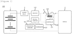
- FIG. 1 is a diagram schematically illustrating a configuration of an apparatus 100 for protecting a MOSFET relay according to an embodiment of the present invention.
- the apparatus 100 for protecting a MOSFET relay may be configured to include a resistor 110 connected to the MOSFET relay 3, a voltage detector 120, and a short-circuit unit 130.
- the resistor 110 is positioned between the MOSFET relay 3 and the fuse 4 and may serve as a means for measuring a current value transmitted from the fuse 4 to the MOSFET relay 3.
- the resistor 110 may be applied with a shunt resistor (or a classification resistor) with a very low resistance value (e.g., 0.001 ohm, etc.) and when an electric conduction current value corresponds to overcurrent of 500 amperes or more and it is thus difficult to connect a voltage measurer (not illustrated) in series, the current value may be inversely calculated using the resistor 110 such as the shunt resistor.
- a shunt resistor or a classification resistor
- a very low resistance value e.g., 0.001 ohm, etc.
- V represents a voltage value (v)
- I represents the current value (A)
- R represents a resistance value ( ⁇ ).
- the resistor 110 when the current value of the current outputted from the battery module 1 corresponds to a very large overcurrent, the resistor 110 according to the present invention may be used to calculate the current value inversely. Meanwhile, since the resistor 110 described in the specification uses the shunt resistor known in the related art, a more detailed description thereof will be omitted.
- the voltage detector 120 may serve to calculate the voltage value of the current electrically conducted to the resistor 110 and determine whether the voltage value exceeds a threshold.
- the voltage detector 120 amplifies the corresponding voltage value by a predetermined multiple number by calculating an electrically conducted voltage value by using the current value of the current electrically conducted along both terminals of the resistor 110 and the resistance value of the resistor 110 and compares the amplified voltage value with a predetermined threshold amplified voltage value to serve to determine whether the amplified voltage value is more than the predetermined threshold amplified voltage value and the role of the voltage detector 120 may be implemented through an operational amplifier 121 and a comparator 122.
- the operational amplifier (OP Amp) 121 amplifies the calculated voltage value by a predetermined multiple number (for example, 10 times or 20 times) to facilitate comparison of the voltage of the comparator 122 to be described below.
- An initial voltage value calculated through the voltage detector 120 is calculated as fine minute voltage such as 0.5 V, 0.6 V, or 0.7 V due to an excessive current value (for example, 500 A or more) of the current which is electrically conducted to the resistor 110. Therefore, by amplifying such minute voltage by 20 times, or the like, the voltage value may be more easily compared in the comparator 122 described below.
- the operational amplifier 121 amplifies the initial voltage value by 20 times and accordingly outputs the amplified voltage value corresponding to 10 V.
- the amplified voltage value thus outputted may be used for determining the overcurrent of the electrical conducted current in the comparator 122 to be described below.
- the operational amplifier 121 may also serve to amplify a threshold voltage range predetermined by a user.
- the threshold voltage range predetermined by the user may mean a voltage protection area that the user arbitrarily sets in order to protect the MOSFET relay 3 from being burned and may mean an interval of a maximum voltage value at which the MOSFET relay 3 operates to a voltage value at the time when the MOSFET relay 3 is burned such as 0.5 V to 1.0 V.
- the threshold voltage range is minute like 0.5 V to 1.0 V due to the excessive current value (for example, 500 A or more) of the current which is electrically conducted to the resistor 110 as described above and the operational amplifier 121 amplifies such a minute threshold voltage range by the predetermined multiple number (for example, 20 times, etc.), and as a result, the threshold amplification voltage range corresponding to 10 V to 20 V is output.
- the output threshold amplification voltage range may serve as an overcurrent judgment reference range of the comparator 122 to be described below.
- the comparator 122 compares the amplified voltage value output from the operational amplifier 121 and the threshold amplified voltage value to serve to determine whether the amplified voltage value is more than the threshold amplified voltage value.
- the threshold amplified voltage value may mean a threshold (for example, 13 V) set by the user within the threshold amplified voltage range (10 V to 20 V) output from the operational amplifier 121 and in this case, it is noted that a value of the threshold amplified voltage value may be changed at any time according to setting by the user.
- the comparator 122 determines that the amplified voltage value which is more than 10 V and less than 13 V is not more than the threshold amplified voltage value, but determines that the amplified voltage value which is more than 13 V is more than the threshold amplified voltage value to apply a heating control signal to the short-circuit unit 130 to be described below.
- a current value of 650A or more may be meaningless and in particular, when the amplified voltage value is more than 13 V to be close to 20 V (a current value (1000 A) at which the MOSFET relay 3 is burned), the MOSFET relay 3 may be dangerous.
- the comparator 122 may determine that the amplified voltage value which is more than 13 V is more than the threshold amplified voltage value and allow the short circuit unit 130 to be described below to short-circuit the fuse 4.
- the short circuit unit 130 may serve to short circuit the fuse 4 according to a result of determining whether the amplified voltage value is more than the threshold amplified voltage value by the comparator 122 and may fuse the fuse through the heating control signal, the short circuit unit 130 may be also referred to as a signal fuse.
- the short circuit unit 130 may be configured to include a controller 131 and a heating element 132 and roles thereof are described below.
- the controller 131 receives the heating control signal from the comparator 122 and then applies a heating signal to the heating element 132 to be described below to serve to heat the heating element 132.
- the controller 131 may adopt a switching device such as a field effect transistor (FET) and it is noted that devices which may serve as the switching device are not limited as an adaptation target of the controller 131 in addition to the field effect transistor (FET).
- FET field effect transistor
- the heating element 132 may be directly or indirectly adjacently connected to the fuse 4 of the circuit and the heating element 132 may serve to receive the heating signal from the controller 131 and generate heat at a high temperature to fuse the fuse 4.
- the heating element 132 may adopt a heating element that emits the heat at the high temperature due to rapid rise of the resistance value by current which flows for an extremely short time such as a positive temperature coefficient thermistor (PTC), etc., and it is noted that devices which may serve as the heating element are not limited as the adaptation target of the heating element 132 in addition to the PTC.
- PTC positive temperature coefficient thermistor
- the amplified voltage value is output by calculating and amplifying the voltage value of the current which is electrically conducted to the resistor 110 through the voltage detector 120 connected with both terminals of the resistor 110 and it is determined whether the amplified voltage value is more than a threshold amplified voltage value (S201).
- the comparator 122 applies the heating control signal to the controller 131 (S202), and as a result, the controller 131 applies the heating signal to the heating element 132 to heat the heating element 132 (S203).
- the fuse 4 is fused by the heat generation by the heating element 132 and the MOSFET relay 3 is protected from the overcurrent (S204).
Landscapes
- Engineering & Computer Science (AREA)
- Power Engineering (AREA)
- Physics & Mathematics (AREA)
- General Physics & Mathematics (AREA)
- Transportation (AREA)
- Mechanical Engineering (AREA)
- Life Sciences & Earth Sciences (AREA)
- Sustainable Development (AREA)
- Sustainable Energy (AREA)
- Emergency Protection Circuit Devices (AREA)
- Protection Of Static Devices (AREA)
- Measurement Of Current Or Voltage (AREA)
Abstract
Description
- This application claims priority to and the benefit of Korean Patent Application No.
10-2016-0044285 - The present invention relates to an apparatus and a method for protecting a MOSFET relay by using a voltage detector and a signal fuse, and more particularly, to an apparatus and a method for protecting a MOSFET relay by using a voltage detector and a signal fuse, which calculate a detection voltage value through a voltage detector from an electrically conducted current value of a MOSFET relay provided in a battery main circuit for a vehicle and pre-block current applied to the MOSFET relay by operating a signal fuse when the calculated voltage value is more than a predetermined threshold to protect the MOSFET relay from being burned.
- In general, in the case of a plug-in hybrid electric vehicle (PHEV) that travels by using energy output from a battery as a power source, it is necessary to charge an internal battery by driving a vehicle motor and in this case, an element called a relay is used to apply current which flows between a charge source and a battery or block the current between the charge source and the battery.
- Moreover, when various elements need to be protected in a situation in which overcurrent which is more than a threshold flows on an internal circuit of the electric vehicle, a state of the relay is changed from an on state to an off state, and as a result, the current on the circuit is blocked to protect various elements.
- Meanwhile, in the electric vehicle, in the case of a relay, especially, a mechanical relay, there are problems such as frequent noise generation and frequent maintenance due to welding. Therefore, in order to solve the problems, the relay is implemented and applied by using a metal oxide silicon field effect transistor (MOSFET) which is a semiconductor device instead of the mechanical relay.
- In this case, since there is a fear that the MOSFET relay may be burned or destroyed when overcurrent (for example, current of 1000 A or more) is applied due to characteristics of the device. Therefore, a separate blocking apparatus is required, which is capable of preventing the burning or destroying, but in the related art as the separate blocking apparatus is not present, which is capable of protecting the MOSFET relay itself from being burned, the burned MOSFET relay needs to be replaced with a new MOSFET relay every time.
- Accordingly, the present inventor has invented an apparatus and a method for protecting a MOSFET relay by using a voltage detector and a signal fuse, which calculate a detection voltage value through a voltage detector from an electrically conducted current value of a MOSFET relay provided in a battery main circuit for a vehicle and pre-block current applied to the MOSFET relay by operating a signal fuse when the calculated voltage value is more than a predetermined threshold to protect the MOSFET relay from being burned, in order to solve the problem of a circuit implemented through the MOSFET relay in the related art.
- The present invention is contrived to solve the problem and the present invention has been made in an effort to provide an apparatus and a method for protecting a MOSFET relay by using a voltage detector and a signal fuse, which calculate a detection voltage value through a voltage detector from an electrically conducted current value of a MOSFET relay provided in a battery main circuit for a vehicle and pre-block current applied to the MOSFET relay by operating a signal fuse when the calculated voltage value is more than a predetermined threshold to protect the MOSFET relay from being burned.
- Among embodiments according to the present invention, an apparatus for protecting a MOSFET relay may include: a voltage detector calculating a voltage value of current which is electrically conducted to a resistor and determining whether the voltage value is more than a threshold; and a short circuit unit short-circuiting a fuse on a circuit according to a determination result of the voltage detector.
- In the embodiment, as the fuse is short-circuited, current electrically conducted to the MOSFET relay connected to the resistor may be blocked.
- In the embodiment, the voltage detector may include an operational amplifier (OP Amp) amplifying the voltage value and outputting an amplified voltage value, and a comparator determining whether the amplified voltage value is more than a predetermined threshold amplified voltage value.
- In the embodiment, the short circuit unit may include a controller receiving a heating control signal from the voltage detector, and a heating element connected with the fuse and generating heat by a heating signal applied from the controller, and as the heating element generates the heat, the fuse may be short-circuited.
- In the embodiment, as the determination result of the comparator, when the amplified voltage value is more than the threshold amplified voltage value, the voltage detector may apply the heating control signal to the controller and the controller may heat the heating element by the heating control signal.
- In the embodiment, the controller may be a field effect transistor (FET), and the heating element may be a heating resistor including a PTC.
- In the embodiment, the resistor may be a shunt resistor.
- In the embodiment, the short circuit unit may be a signal fuse.
- According to another embodiment of the present invention, a method for protecting a MOSFET relay may include: calculating, by a voltage detector, a voltage value of current which is electrically conducted to a resistor and determining whether the voltage value is more than a threshold; and short-circuiting, by a short circuit unit, a fuse on a circuit according to a determination result of the voltage detector.
- In the embodiment, the determining of whether the voltage value is more than the threshold may include measuring a current value of the current electrically conducted to the resistor, calculating the voltage value of the current based on the current value and a resistance value of the resistor, amplifying the voltage value to the amplified voltage value through an operational amplifier (OP Amp), and determining, by a comparator, whether the amplified voltage value is more than a predetermined threshold amplified voltage value.
- In the embodiment, the short-circuiting of the fuse may include applying, by the voltage detector, a heating control signal to the short circuit unit, heating, by a controller included in the short circuit unit, a heating element, and short-circuiting the fuse as the heating element is heated.
- In the embodiment, the determining of whether the amplified voltage value is more than the predetermined threshold amplified voltage value may include setting the threshold amplified voltage value based on a threshold current range corresponding to a current value of 500 to 1000 amperes.
- According to an embodiment of the present invention, an apparatus and a method for protecting a MOSFET relay have an advantage of protecting a MOSFET relay element itself from overcurrent by preventing current which is more than an electric conduction capability (1000 amperes, etc.) of the MOSFET relay before applying the current to the MOSFET relay.
- Further, the present invention has an advantage of more easily setting a threshold amplification voltage value by amplifying a voltage difference between both terminals of a resistor minutely output as 0.5 V or less through an operation amplifier (OP Amp).
-
-
FIG. 1 is a diagram schematically illustrating a configuration of anapparatus 100 for protecting a MOSFET relay according to an embodiment of the present invention. -
FIG. 2 is a flowchart schematically illustrating an order of protecting the MOSFET relay through theapparatus 100 for protecting a MOSFET relay, which is illustrated inFIG. 1 . - Hereinafter, a preferred embodiment is presented in order to assist understanding of the present invention. However, the following embodiment is just provided to more easily understand the present invention and contents of the present invention are not limited by the embodiment.
- In addition, a battery module 1 shown in the drawings of the specification may refer to a secondary battery applicable to a plug in hybrid electric vehicle (PHEV) or an electric vehicle (EV) and a vehicle 2 may mean the plug in hybrid electric vehicle or the electric vehicle as described above.
- Further, in the specification, a
MOSFET relay 3 may mean a device implementing a relay (switching device) using a metal oxide semiconductor field effect transistor (MOSFET) and in this case, the detailed description of theMOSFET relay 3 device itself will be omitted because theMOSFET relay 3 adopts a technique known in the related art. - Further, in the specification, a fuse 4 may mean a device which is generally provided on a circuit and fused by overcurrent to serve to cut off current in the circuit. Likewise, since the fuse 4 uses the technique known in the related art, the detailed description of the fuse 4 device itself will be omitted.
-
FIG. 1 is a diagram schematically illustrating a configuration of anapparatus 100 for protecting a MOSFET relay according to an embodiment of the present invention. - Referring to
FIG. 1 , theapparatus 100 for protecting a MOSFET relay according to the embodiment of the present invention may be configured to include aresistor 110 connected to theMOSFET relay 3, avoltage detector 120, and a short-circuit unit 130. - First, the
resistor 110 is positioned between theMOSFET relay 3 and the fuse 4 and may serve as a means for measuring a current value transmitted from the fuse 4 to theMOSFET relay 3. - More specifically, the
resistor 110 may be applied with a shunt resistor (or a classification resistor) with a very low resistance value (e.g., 0.001 ohm, etc.) and when an electric conduction current value corresponds to overcurrent of 500 amperes or more and it is thus difficult to connect a voltage measurer (not illustrated) in series, the current value may be inversely calculated using theresistor 110 such as the shunt resistor. - A process of inversely calculating the current value by using the
resistor 110 such as the shunt resistor will be schematically described below.
- Herein, V represents a voltage value (v), I represents the current value (A), and R represents a resistance value (Ω).
- As an example, when the voltage value V of the current outputted from the battery module 1 is 5 V and the resistance value R is 0.001 Ω, it can be seen that the current value is calculated as 5/0.001= 500 A by the equation.
- As another example, when the voltage value V of the current outputted from the battery module 1 is 10 V and the resistance value R is 0.001 Ω, it can be seen that the current value is calculated as 10/0.001= 1000 A by the equation.
- As described above, when the current value of the current outputted from the battery module 1 corresponds to a very large overcurrent, the
resistor 110 according to the present invention may be used to calculate the current value inversely. Meanwhile, since theresistor 110 described in the specification uses the shunt resistor known in the related art, a more detailed description thereof will be omitted. - Next, the
voltage detector 120 may serve to calculate the voltage value of the current electrically conducted to theresistor 110 and determine whether the voltage value exceeds a threshold. - More specifically, the
voltage detector 120 amplifies the corresponding voltage value by a predetermined multiple number by calculating an electrically conducted voltage value by using the current value of the current electrically conducted along both terminals of theresistor 110 and the resistance value of theresistor 110 and compares the amplified voltage value with a predetermined threshold amplified voltage value to serve to determine whether the amplified voltage value is more than the predetermined threshold amplified voltage value and the role of thevoltage detector 120 may be implemented through anoperational amplifier 121 and acomparator 122. - The operational amplifier (OP Amp) 121 amplifies the calculated voltage value by a predetermined multiple number (for example, 10 times or 20 times) to facilitate comparison of the voltage of the
comparator 122 to be described below. - An initial voltage value calculated through the
voltage detector 120 is calculated as fine minute voltage such as 0.5 V, 0.6 V, or 0.7 V due to an excessive current value (for example, 500 A or more) of the current which is electrically conducted to theresistor 110. Therefore, by amplifying such minute voltage by 20 times, or the like, the voltage value may be more easily compared in thecomparator 122 described below. - For example, when the initial voltage value calculated through the
voltage detector 122 is 0.5 V, theoperational amplifier 121 amplifies the initial voltage value by 20 times and accordingly outputs the amplified voltage value corresponding to 10 V. The amplified voltage value thus outputted may be used for determining the overcurrent of the electrical conducted current in thecomparator 122 to be described below. - In the embodiment, the
operational amplifier 121 may also serve to amplify a threshold voltage range predetermined by a user. - Herein, the threshold voltage range predetermined by the user may mean a voltage protection area that the user arbitrarily sets in order to protect the
MOSFET relay 3 from being burned and may mean an interval of a maximum voltage value at which theMOSFET relay 3 operates to a voltage value at the time when theMOSFET relay 3 is burned such as 0.5 V to 1.0 V. - In this case, the threshold voltage range is minute like 0.5 V to 1.0 V due to the excessive current value (for example, 500 A or more) of the current which is electrically conducted to the
resistor 110 as described above and theoperational amplifier 121 amplifies such a minute threshold voltage range by the predetermined multiple number (for example, 20 times, etc.), and as a result, the threshold amplification voltage range corresponding to 10 V to 20 V is output. The output threshold amplification voltage range may serve as an overcurrent judgment reference range of thecomparator 122 to be described below. - The
comparator 122 compares the amplified voltage value output from theoperational amplifier 121 and the threshold amplified voltage value to serve to determine whether the amplified voltage value is more than the threshold amplified voltage value. - Herein, the threshold amplified voltage value may mean a threshold (for example, 13 V) set by the user within the threshold amplified voltage range (10 V to 20 V) output from the
operational amplifier 121 and in this case, it is noted that a value of the threshold amplified voltage value may be changed at any time according to setting by the user. - For example, assuming that the threshold amplified voltage value set by the user is 13 V, the
comparator 122 determines that the amplified voltage value which is more than 10 V and less than 13 V is not more than the threshold amplified voltage value, but determines that the amplified voltage value which is more than 13 V is more than the threshold amplified voltage value to apply a heating control signal to the short-circuit unit 130 to be described below. - In this case, since the current value 650A corresponding to 13 V is not an overcurrent enough to burn the
MOSFET relay 3, but already exceeds the maximum current value (520A) at which theMOSFET relay 3 operates, a current value of 650 A or more may be meaningless and in particular, when the amplified voltage value is more than 13 V to be close to 20 V (a current value (1000 A) at which theMOSFET relay 3 is burned), theMOSFET relay 3 may be dangerous. - Therefore, the
comparator 122 may determine that the amplified voltage value which is more than 13 V is more than the threshold amplified voltage value and allow theshort circuit unit 130 to be described below to short-circuit the fuse 4. - Next, since the
short circuit unit 130 may serve to short circuit the fuse 4 according to a result of determining whether the amplified voltage value is more than the threshold amplified voltage value by thecomparator 122 and may fuse the fuse through the heating control signal, theshort circuit unit 130 may be also referred to as a signal fuse. - The
short circuit unit 130 may be configured to include acontroller 131 and aheating element 132 and roles thereof are described below. - The
controller 131 receives the heating control signal from thecomparator 122 and then applies a heating signal to theheating element 132 to be described below to serve to heat theheating element 132. - The
controller 131 may adopt a switching device such as a field effect transistor (FET) and it is noted that devices which may serve as the switching device are not limited as an adaptation target of thecontroller 131 in addition to the field effect transistor (FET). - The
heating element 132 may be directly or indirectly adjacently connected to the fuse 4 of the circuit and theheating element 132 may serve to receive the heating signal from thecontroller 131 and generate heat at a high temperature to fuse the fuse 4. - The
heating element 132 may adopt a heating element that emits the heat at the high temperature due to rapid rise of the resistance value by current which flows for an extremely short time such as a positive temperature coefficient thermistor (PTC), etc., and it is noted that devices which may serve as the heating element are not limited as the adaptation target of theheating element 132 in addition to the PTC. - Next, an order in which the
apparatus 100 for protecting a MOSFET relay operates will be schematically described throughFIG. 2 . - Referring to
FIG. 2 , first, the amplified voltage value is output by calculating and amplifying the voltage value of the current which is electrically conducted to theresistor 110 through thevoltage detector 120 connected with both terminals of theresistor 110 and it is determined whether the amplified voltage value is more than a threshold amplified voltage value (S201). - Next, when it is determined that the amplified voltage value is more than the threshold amplified voltage value, the
comparator 122 applies the heating control signal to the controller 131 (S202), and as a result, thecontroller 131 applies the heating signal to theheating element 132 to heat the heating element 132 (S203). - As a result, the fuse 4 is fused by the heat generation by the
heating element 132 and theMOSFET relay 3 is protected from the overcurrent (S204). - The present invention has been described with reference to the preferred embodiments, but those skilled in the art will understand that the present invention can be variously modified and changed without departing from the spirit and the scope of the present invention which are defined in the appended claims.
Claims (11)
- An apparatus for protecting a MOSFET relay, the apparatus comprising:a voltage detector calculating a voltage value of current which is electrically conducted to a resistor and determining whether the voltage value is more than a threshold; anda short circuit unit short-circuiting a fuse on a circuit according to a determination result of the voltage detector,wherein as the fuse is short-circuited, current electrically conducted to the MOSFET relay connected to the resistor is blocked.
- The apparatus of claim 1, wherein the voltage detector includes
an operational amplifier (OP Amp) amplifying the voltage value and outputting an amplified voltage value, and
a comparator determining whether the amplified voltage value is more than a predetermined threshold amplified voltage value. - The apparatus of claim 2, wherein the short circuit unit includes
a controller receiving a heating control signal from the voltage detector, and
a heating element connected with the fuse and generating heat by a heating signal applied from the controller, and
as the heating element generates the heat, the fuse is short-circuited. - The apparatus of claim 3, wherein as the determination result of the comparator, when the amplified voltage value is more than the threshold amplified voltage value, the voltage detector applies the heating control signal to the controller and the controller heats the heating element by the heating control signal.
- The apparatus of claim 3, wherein the controller is a field effect transistor (FET), and
the heating element is a heating resistor including a PTC. - The apparatus of claim 1, wherein the resistor is a shunt resistor.
- The apparatus of claim 1, wherein the short circuit unit is a signal fuse.
- A method for protecting a MOSFET relay, the method comprising:calculating, by a voltage detector, a voltage value of current which is electrically conducted to a resistor and determining whether the voltage value is more than a threshold; andshort-circuiting, by a short circuit unit, a fuse on a circuit according to a determination result of the voltage detector.
- The method of claim 8, wherein the determining of whether the voltage value is more than the threshold includes
measuring a current value of the current electrically conducted to the resistor,
calculating the voltage value of the current based on the current value and a resistance value of the resistor,
amplifying the voltage value to the amplified voltage value through an operational amplifier (OP Amp), and
determining, by a comparator, whether the amplified voltage value is more than a predetermined threshold amplified voltage value. - The method of claim 8, wherein the short-circuiting of the fuse includes
applying, by the voltage detector, a heating control signal to the short circuit unit,
heating, by a controller included in the short circuit unit, a heating element, and
short-circuiting the fuse as the heating element is heated. - The method of claim 9, wherein the determining of whether the amplified voltage value is more than the predetermined threshold amplified voltage value includes setting the threshold amplified voltage value based on a threshold current range corresponding to a current value of 500 to 1000 amperes.
Applications Claiming Priority (2)
| Application Number | Priority Date | Filing Date | Title |
|---|---|---|---|
| KR1020160044285A KR20170116472A (en) | 2016-04-11 | 2016-04-11 | Apparatus and method for protecting MOSFET relay using a voltage detector and signal fuse |
| PCT/KR2017/003869 WO2017179869A2 (en) | 2016-04-11 | 2017-04-10 | Apparatus and method for protecting mosfet relay by using voltage detector and signal fuse |
Publications (3)
| Publication Number | Publication Date |
|---|---|
| EP3413420A2 true EP3413420A2 (en) | 2018-12-12 |
| EP3413420A4 EP3413420A4 (en) | 2019-03-13 |
| EP3413420B1 EP3413420B1 (en) | 2023-09-27 |
Family
ID=60042622
Family Applications (1)
| Application Number | Title | Priority Date | Filing Date |
|---|---|---|---|
| EP17782624.5A Active EP3413420B1 (en) | 2016-04-11 | 2017-04-10 | Apparatus and method for protecting mosfet relay by using voltage detector and signal fuse |
Country Status (9)
| Country | Link |
|---|---|
| US (1) | US10862296B2 (en) |
| EP (1) | EP3413420B1 (en) |
| JP (1) | JP6732297B2 (en) |
| KR (1) | KR20170116472A (en) |
| CN (1) | CN108780992A (en) |
| ES (1) | ES2959270T3 (en) |
| HU (1) | HUE063459T2 (en) |
| PL (1) | PL3413420T3 (en) |
| WO (1) | WO2017179869A2 (en) |
Families Citing this family (8)
| Publication number | Priority date | Publication date | Assignee | Title |
|---|---|---|---|---|
| CN109039313A (en) * | 2018-08-02 | 2018-12-18 | 上海沪工汽车电器有限公司 | Solid-state relay |
| KR102390002B1 (en) | 2018-08-31 | 2022-04-22 | 주식회사 엘지에너지솔루션 | System and method for controlling a fuse using detecting a failure mode |
| KR102181353B1 (en) * | 2019-05-17 | 2020-11-20 | 허정 | Apparatus and method for load detection |
| KR102841673B1 (en) | 2019-07-10 | 2025-07-31 | 주식회사 엘지에너지솔루션 | Apparatus and method for detecting fault of battery pack |
| KR102940303B1 (en) * | 2020-01-03 | 2026-03-16 | 주식회사 엘지에너지솔루션 | Apparatus for controlling relay |
| CN112462299A (en) * | 2020-10-20 | 2021-03-09 | 云南电网有限责任公司昆明供电局 | Portable relay protection secondary open-loop wireless verification device |
| CN112918326B (en) * | 2020-12-28 | 2023-02-28 | 中国第一汽车股份有限公司 | A battery management system, method, vehicle and medium |
| CN116191582A (en) * | 2022-09-02 | 2023-05-30 | 肇庆小鹏汽车有限公司 | Protection circuit, battery pack, vehicle and control method |
Family Cites Families (37)
| Publication number | Priority date | Publication date | Assignee | Title |
|---|---|---|---|---|
| US4346424A (en) * | 1980-02-22 | 1982-08-24 | Eaton Corporation | Electronic remote control D.C. power controller and circuit breaker |
| JP3322925B2 (en) * | 1992-12-28 | 2002-09-09 | 京セラ株式会社 | Battery charging control system |
| FR2713372B1 (en) * | 1993-12-01 | 1996-03-01 | Neopost Ind | Thermal protection device for secure electronic device, in particular postage meter. |
| JPH08116627A (en) * | 1994-10-14 | 1996-05-07 | Sony Corp | Battery pack protection circuit |
| JPH09158717A (en) * | 1995-12-08 | 1997-06-17 | Toyota Motor Corp | Power supply controller for electrically heated catalyst |
| JP3416461B2 (en) * | 1997-05-30 | 2003-06-16 | キヤノン株式会社 | Solar battery charge control device |
| JP3363074B2 (en) | 1997-08-08 | 2003-01-07 | 株式会社オートネットワーク技術研究所 | Overcurrent detection circuit |
| US6288881B1 (en) * | 1999-08-17 | 2001-09-11 | John A. Melvin | Battery voltage regulator protection circuits |
| US6286976B1 (en) * | 2000-02-02 | 2001-09-11 | The United States Of America As Represented By The Secretary Of The Army | Dome light with removable emergency light module |
| US6349023B1 (en) * | 2000-02-24 | 2002-02-19 | Robotic Vision Systems, Inc. | Power control system for illumination array |
| JP2002118258A (en) * | 2000-10-10 | 2002-04-19 | Sanyo Electric Co Ltd | Mosfet and protective circuit device using that |
| KR200222068Y1 (en) * | 2000-11-28 | 2001-05-02 | 낙원개발주식회사 | crime prevention system for a window |
| US6813129B2 (en) * | 2001-12-14 | 2004-11-02 | Alcoa Fujikura Limited | Self-diagnostic solid state relay for detection of open load circuit |
| JP4411897B2 (en) * | 2003-07-30 | 2010-02-10 | 株式会社ジェイテクト | DC booster failure determination device |
| US7304828B1 (en) * | 2004-09-22 | 2007-12-04 | Shvartsman Vladimir A | Intelligent solid state relay/breaker |
| US7952330B2 (en) * | 2005-04-20 | 2011-05-31 | Panasonic Corporation | Secondary battery protection circuit, battery pack and thermosensitive protection switch device |
| JP4509040B2 (en) * | 2006-02-08 | 2010-07-21 | 三洋電機株式会社 | Pack battery control method |
| JP5076337B2 (en) * | 2006-03-13 | 2012-11-21 | ソニー株式会社 | Battery pack device and battery pack device control method |
| KR20080015215A (en) | 2006-08-14 | 2008-02-19 | 주식회사 엘지화학 | Secondary battery protection circuit for self-monitoring of fuse failure, battery pack and fuse failure monitoring method using the same, and method for classifying battery assembly containing defective fuse |
| CN101281057B (en) * | 2007-04-02 | 2011-06-22 | 鸿富锦精密工业(深圳)有限公司 | Airflow detection device |
| KR100781131B1 (en) | 2007-07-10 | 2007-11-30 | 삼화디에스피주식회사 | Electronic solid state relay with overcurrent / short circuit relay |
| JP5053337B2 (en) * | 2009-07-21 | 2012-10-17 | レノボ・シンガポール・プライベート・リミテッド | Protection element and protection system for storage battery |
| CN102273044B (en) * | 2009-07-31 | 2015-04-22 | 松下电器产业株式会社 | Protection circuit, battery pack, and charging system |
| JP5669086B2 (en) | 2009-10-27 | 2015-02-12 | パナソニックIpマネジメント株式会社 | Hybrid relay |
| CN102129037B (en) | 2010-01-18 | 2014-10-22 | 光阳工业股份有限公司 | Electric vehicle residual power display system and residual power display method thereof |
| US9450401B2 (en) * | 2012-03-20 | 2016-09-20 | Apple Inc. | Controlling a thermally sensitive over-current protector |
| JP5954164B2 (en) * | 2012-12-25 | 2016-07-20 | トヨタ自動車株式会社 | Overcurrent protection device and overcurrent protection method |
| CN104919670A (en) | 2013-01-11 | 2015-09-16 | 泰科电子日本合同会社 | Protection element |
| TWI484710B (en) * | 2013-03-19 | 2015-05-11 | Delta Electronics Inc | Electronic fuse apparatus and method of operating the same |
| US10483061B2 (en) | 2013-07-02 | 2019-11-19 | Littelfuse Japan G.K. | Protective device |
| JP6347967B2 (en) | 2013-11-29 | 2018-06-27 | マクセルホールディングス株式会社 | Battery protection circuit and battery pack |
| US20160099559A1 (en) * | 2014-10-01 | 2016-04-07 | Continental Automotive Systems, Inc. | Overcurrent protection for an automotive instrument cluster |
| JP6314845B2 (en) * | 2015-01-08 | 2018-04-25 | 株式会社オートネットワーク技術研究所 | Electrical junction box |
| IL237775B (en) * | 2015-03-16 | 2019-03-31 | Redler Tech Ltd | Automatic, highly reliable, fully redundant electornic circuit breaker that includes means for preventing short-circuit overcurrent |
| US20180069394A1 (en) * | 2016-09-06 | 2018-03-08 | Monolithic Power Systems, Inc. | Power-limit protection circuit with an efuse element |
| KR102051176B1 (en) * | 2016-10-05 | 2019-12-02 | 주식회사 엘지화학 | Apparatus and methode for fuse diagnosis using voltage distribution |
| US20190162787A1 (en) * | 2017-11-27 | 2019-05-30 | Maxim Hurwicz | Circuit breaker locator and tester |
-
2016
- 2016-04-11 KR KR1020160044285A patent/KR20170116472A/en not_active Ceased
-
2017
- 2017-04-10 EP EP17782624.5A patent/EP3413420B1/en active Active
- 2017-04-10 PL PL17782624.5T patent/PL3413420T3/en unknown
- 2017-04-10 US US16/079,487 patent/US10862296B2/en active Active
- 2017-04-10 ES ES17782624T patent/ES2959270T3/en active Active
- 2017-04-10 HU HUE17782624A patent/HUE063459T2/en unknown
- 2017-04-10 WO PCT/KR2017/003869 patent/WO2017179869A2/en not_active Ceased
- 2017-04-10 JP JP2018543175A patent/JP6732297B2/en active Active
- 2017-04-10 CN CN201780015371.9A patent/CN108780992A/en active Pending
Also Published As
| Publication number | Publication date |
|---|---|
| PL3413420T3 (en) | 2023-12-18 |
| US10862296B2 (en) | 2020-12-08 |
| ES2959270T3 (en) | 2024-02-22 |
| EP3413420B1 (en) | 2023-09-27 |
| HUE063459T2 (en) | 2024-01-28 |
| EP3413420A4 (en) | 2019-03-13 |
| KR20170116472A (en) | 2017-10-19 |
| JP2019506834A (en) | 2019-03-07 |
| CN108780992A (en) | 2018-11-09 |
| US20190052257A1 (en) | 2019-02-14 |
| WO2017179869A2 (en) | 2017-10-19 |
| JP6732297B2 (en) | 2020-07-29 |
| WO2017179869A3 (en) | 2018-08-02 |
Similar Documents
| Publication | Publication Date | Title |
|---|---|---|
| EP3413420B1 (en) | Apparatus and method for protecting mosfet relay by using voltage detector and signal fuse | |
| JP5480957B2 (en) | Load circuit protection device | |
| JP6014404B2 (en) | Earth leakage detector | |
| EP3820009B1 (en) | Protection system | |
| KR20170053129A (en) | Battery cell with a rapid discharge unit and rapid discharging method for such a battery cell | |
| CN107623514A (en) | Semiconductor switch control device | |
| US9130366B2 (en) | Electronic ignition system for an engine of a vehicle in case of failure | |
| KR20160070516A (en) | Gate driver circuit and method for preventing arm short | |
| CN103324240B (en) | Semiconductor device | |
| CN107925257A (en) | Wire protector | |
| JPWO2018168981A1 (en) | Current detector | |
| WO2018015462A1 (en) | Ideal diode with active reverse voltage protection | |
| US10826284B2 (en) | Self-tripping explosive fuse | |
| JP2015173019A (en) | On-failure detection device and method thereof | |
| CN117178453A (en) | Vehicle-mounted switching device | |
| US8432657B2 (en) | Protection apparatus of load circuit | |
| US9923364B2 (en) | Load driving device, vehicle air-conditioning apparatus, and load short-circuit protection circuit | |
| KR20200129084A (en) | Apparatus and method for protecting MOSFET relay using a voltage detector and signal fuse | |
| US12587008B2 (en) | Cutoff control apparatus having a first cutoff unit and a second cutoff unit | |
| JP6468142B2 (en) | In-vehicle relay temperature detection system | |
| KR20150139451A (en) | Fuse circuit, fuse adjusting circuit, fuse adjusting method, program and recording medium | |
| CN107710371B (en) | System and method for independently controlling relays using bimetal | |
| JP2013165631A (en) | Switching circuit and battery pack | |
| KR101741077B1 (en) | Method for electrical switching in oxide semiconductor devices | |
| JP2015035924A (en) | Overcurrent protective device |
Legal Events
| Date | Code | Title | Description |
|---|---|---|---|
| STAA | Information on the status of an ep patent application or granted ep patent |
Free format text: STATUS: THE INTERNATIONAL PUBLICATION HAS BEEN MADE |
|
| PUAI | Public reference made under article 153(3) epc to a published international application that has entered the european phase |
Free format text: ORIGINAL CODE: 0009012 |
|
| STAA | Information on the status of an ep patent application or granted ep patent |
Free format text: STATUS: REQUEST FOR EXAMINATION WAS MADE |
|
| 17P | Request for examination filed |
Effective date: 20180907 |
|
| AK | Designated contracting states |
Kind code of ref document: A2 Designated state(s): AL AT BE BG CH CY CZ DE DK EE ES FI FR GB GR HR HU IE IS IT LI LT LU LV MC MK MT NL NO PL PT RO RS SE SI SK SM TR |
|
| AX | Request for extension of the european patent |
Extension state: BA ME |
|
| A4 | Supplementary search report drawn up and despatched |
Effective date: 20190212 |
|
| RIC1 | Information provided on ipc code assigned before grant |
Ipc: G01R 19/00 20060101ALI20190206BHEP Ipc: H02H 3/08 20060101ALI20190206BHEP Ipc: B60L 15/22 20060101ALI20190206BHEP Ipc: H02H 3/20 20060101ALI20190206BHEP Ipc: G01R 19/165 20060101ALI20190206BHEP Ipc: H02H 7/20 20060101AFI20190206BHEP Ipc: G01R 1/20 20060101ALI20190206BHEP |
|
| DAV | Request for validation of the european patent (deleted) | ||
| DAX | Request for extension of the european patent (deleted) | ||
| STAA | Information on the status of an ep patent application or granted ep patent |
Free format text: STATUS: EXAMINATION IS IN PROGRESS |
|
| 17Q | First examination report despatched |
Effective date: 20210922 |
|
| RAP1 | Party data changed (applicant data changed or rights of an application transferred) |
Owner name: LG ENERGY SOLUTION LTD. |
|
| RAP3 | Party data changed (applicant data changed or rights of an application transferred) |
Owner name: LG ENERGY SOLUTION, LTD. |
|
| GRAP | Despatch of communication of intention to grant a patent |
Free format text: ORIGINAL CODE: EPIDOSNIGR1 |
|
| STAA | Information on the status of an ep patent application or granted ep patent |
Free format text: STATUS: GRANT OF PATENT IS INTENDED |
|
| INTG | Intention to grant announced |
Effective date: 20230512 |
|
| P01 | Opt-out of the competence of the unified patent court (upc) registered |
Effective date: 20230516 |
|
| GRAS | Grant fee paid |
Free format text: ORIGINAL CODE: EPIDOSNIGR3 |
|
| GRAA | (expected) grant |
Free format text: ORIGINAL CODE: 0009210 |
|
| STAA | Information on the status of an ep patent application or granted ep patent |
Free format text: STATUS: THE PATENT HAS BEEN GRANTED |
|
| AK | Designated contracting states |
Kind code of ref document: B1 Designated state(s): AL AT BE BG CH CY CZ DE DK EE ES FI FR GB GR HR HU IE IS IT LI LT LU LV MC MK MT NL NO PL PT RO RS SE SI SK SM TR |
|
| REG | Reference to a national code |
Ref country code: GB Ref legal event code: FG4D |
|
| REG | Reference to a national code |
Ref country code: CH Ref legal event code: EP |
|
| REG | Reference to a national code |
Ref country code: DE Ref legal event code: R096 Ref document number: 602017074679 Country of ref document: DE |
|
| REG | Reference to a national code |
Ref country code: SE Ref legal event code: TRGR |
|
| REG | Reference to a national code |
Ref country code: IE Ref legal event code: FG4D |
|
| REG | Reference to a national code |
Ref country code: LT Ref legal event code: MG9D |
|
| PG25 | Lapsed in a contracting state [announced via postgrant information from national office to epo] |
Ref country code: GR Free format text: LAPSE BECAUSE OF FAILURE TO SUBMIT A TRANSLATION OF THE DESCRIPTION OR TO PAY THE FEE WITHIN THE PRESCRIBED TIME-LIMIT Effective date: 20231228 |
|
| REG | Reference to a national code |
Ref country code: HU Ref legal event code: AG4A Ref document number: E063459 Country of ref document: HU |
|
| PG25 | Lapsed in a contracting state [announced via postgrant information from national office to epo] |
Ref country code: RS Free format text: LAPSE BECAUSE OF FAILURE TO SUBMIT A TRANSLATION OF THE DESCRIPTION OR TO PAY THE FEE WITHIN THE PRESCRIBED TIME-LIMIT Effective date: 20230927 Ref country code: NO Free format text: LAPSE BECAUSE OF FAILURE TO SUBMIT A TRANSLATION OF THE DESCRIPTION OR TO PAY THE FEE WITHIN THE PRESCRIBED TIME-LIMIT Effective date: 20231227 Ref country code: LV Free format text: LAPSE BECAUSE OF FAILURE TO SUBMIT A TRANSLATION OF THE DESCRIPTION OR TO PAY THE FEE WITHIN THE PRESCRIBED TIME-LIMIT Effective date: 20230927 Ref country code: LT Free format text: LAPSE BECAUSE OF FAILURE TO SUBMIT A TRANSLATION OF THE DESCRIPTION OR TO PAY THE FEE WITHIN THE PRESCRIBED TIME-LIMIT Effective date: 20230927 Ref country code: HR Free format text: LAPSE BECAUSE OF FAILURE TO SUBMIT A TRANSLATION OF THE DESCRIPTION OR TO PAY THE FEE WITHIN THE PRESCRIBED TIME-LIMIT Effective date: 20230927 Ref country code: GR Free format text: LAPSE BECAUSE OF FAILURE TO SUBMIT A TRANSLATION OF THE DESCRIPTION OR TO PAY THE FEE WITHIN THE PRESCRIBED TIME-LIMIT Effective date: 20231228 Ref country code: FI Free format text: LAPSE BECAUSE OF FAILURE TO SUBMIT A TRANSLATION OF THE DESCRIPTION OR TO PAY THE FEE WITHIN THE PRESCRIBED TIME-LIMIT Effective date: 20230927 |
|
| REG | Reference to a national code |
Ref country code: NL Ref legal event code: MP Effective date: 20230927 |
|
| REG | Reference to a national code |
Ref country code: AT Ref legal event code: MK05 Ref document number: 1616355 Country of ref document: AT Kind code of ref document: T Effective date: 20230927 |
|
| REG | Reference to a national code |
Ref country code: ES Ref legal event code: FG2A Ref document number: 2959270 Country of ref document: ES Kind code of ref document: T3 Effective date: 20240222 |
|
| PG25 | Lapsed in a contracting state [announced via postgrant information from national office to epo] |
Ref country code: NL Free format text: LAPSE BECAUSE OF FAILURE TO SUBMIT A TRANSLATION OF THE DESCRIPTION OR TO PAY THE FEE WITHIN THE PRESCRIBED TIME-LIMIT Effective date: 20230927 |
|
| PG25 | Lapsed in a contracting state [announced via postgrant information from national office to epo] |
Ref country code: IS Free format text: LAPSE BECAUSE OF FAILURE TO SUBMIT A TRANSLATION OF THE DESCRIPTION OR TO PAY THE FEE WITHIN THE PRESCRIBED TIME-LIMIT Effective date: 20240127 |
|
| PG25 | Lapsed in a contracting state [announced via postgrant information from national office to epo] |
Ref country code: AT Free format text: LAPSE BECAUSE OF FAILURE TO SUBMIT A TRANSLATION OF THE DESCRIPTION OR TO PAY THE FEE WITHIN THE PRESCRIBED TIME-LIMIT Effective date: 20230927 |
|
| PG25 | Lapsed in a contracting state [announced via postgrant information from national office to epo] |
Ref country code: SM Free format text: LAPSE BECAUSE OF FAILURE TO SUBMIT A TRANSLATION OF THE DESCRIPTION OR TO PAY THE FEE WITHIN THE PRESCRIBED TIME-LIMIT Effective date: 20230927 Ref country code: RO Free format text: LAPSE BECAUSE OF FAILURE TO SUBMIT A TRANSLATION OF THE DESCRIPTION OR TO PAY THE FEE WITHIN THE PRESCRIBED TIME-LIMIT Effective date: 20230927 Ref country code: IS Free format text: LAPSE BECAUSE OF FAILURE TO SUBMIT A TRANSLATION OF THE DESCRIPTION OR TO PAY THE FEE WITHIN THE PRESCRIBED TIME-LIMIT Effective date: 20240127 Ref country code: EE Free format text: LAPSE BECAUSE OF FAILURE TO SUBMIT A TRANSLATION OF THE DESCRIPTION OR TO PAY THE FEE WITHIN THE PRESCRIBED TIME-LIMIT Effective date: 20230927 Ref country code: CZ Free format text: LAPSE BECAUSE OF FAILURE TO SUBMIT A TRANSLATION OF THE DESCRIPTION OR TO PAY THE FEE WITHIN THE PRESCRIBED TIME-LIMIT Effective date: 20230927 Ref country code: AT Free format text: LAPSE BECAUSE OF FAILURE TO SUBMIT A TRANSLATION OF THE DESCRIPTION OR TO PAY THE FEE WITHIN THE PRESCRIBED TIME-LIMIT Effective date: 20230927 Ref country code: PT Free format text: LAPSE BECAUSE OF FAILURE TO SUBMIT A TRANSLATION OF THE DESCRIPTION OR TO PAY THE FEE WITHIN THE PRESCRIBED TIME-LIMIT Effective date: 20240129 Ref country code: SK Free format text: LAPSE BECAUSE OF FAILURE TO SUBMIT A TRANSLATION OF THE DESCRIPTION OR TO PAY THE FEE WITHIN THE PRESCRIBED TIME-LIMIT Effective date: 20230927 |
|
| PG25 | Lapsed in a contracting state [announced via postgrant information from national office to epo] |
Ref country code: IT Free format text: LAPSE BECAUSE OF FAILURE TO SUBMIT A TRANSLATION OF THE DESCRIPTION OR TO PAY THE FEE WITHIN THE PRESCRIBED TIME-LIMIT Effective date: 20230927 |
|
| REG | Reference to a national code |
Ref country code: DE Ref legal event code: R097 Ref document number: 602017074679 Country of ref document: DE |
|
| PG25 | Lapsed in a contracting state [announced via postgrant information from national office to epo] |
Ref country code: DK Free format text: LAPSE BECAUSE OF FAILURE TO SUBMIT A TRANSLATION OF THE DESCRIPTION OR TO PAY THE FEE WITHIN THE PRESCRIBED TIME-LIMIT Effective date: 20230927 |
|
| PG25 | Lapsed in a contracting state [announced via postgrant information from national office to epo] |
Ref country code: DK Free format text: LAPSE BECAUSE OF FAILURE TO SUBMIT A TRANSLATION OF THE DESCRIPTION OR TO PAY THE FEE WITHIN THE PRESCRIBED TIME-LIMIT Effective date: 20230927 |
|
| PLBE | No opposition filed within time limit |
Free format text: ORIGINAL CODE: 0009261 |
|
| STAA | Information on the status of an ep patent application or granted ep patent |
Free format text: STATUS: NO OPPOSITION FILED WITHIN TIME LIMIT |
|
| 26N | No opposition filed |
Effective date: 20240628 |
|
| PG25 | Lapsed in a contracting state [announced via postgrant information from national office to epo] |
Ref country code: SI Free format text: LAPSE BECAUSE OF FAILURE TO SUBMIT A TRANSLATION OF THE DESCRIPTION OR TO PAY THE FEE WITHIN THE PRESCRIBED TIME-LIMIT Effective date: 20230927 |
|
| PG25 | Lapsed in a contracting state [announced via postgrant information from national office to epo] |
Ref country code: SI Free format text: LAPSE BECAUSE OF FAILURE TO SUBMIT A TRANSLATION OF THE DESCRIPTION OR TO PAY THE FEE WITHIN THE PRESCRIBED TIME-LIMIT Effective date: 20230927 |
|
| PG25 | Lapsed in a contracting state [announced via postgrant information from national office to epo] |
Ref country code: BG Free format text: LAPSE BECAUSE OF FAILURE TO SUBMIT A TRANSLATION OF THE DESCRIPTION OR TO PAY THE FEE WITHIN THE PRESCRIBED TIME-LIMIT Effective date: 20230927 |
|
| PG25 | Lapsed in a contracting state [announced via postgrant information from national office to epo] |
Ref country code: MC Free format text: LAPSE BECAUSE OF FAILURE TO SUBMIT A TRANSLATION OF THE DESCRIPTION OR TO PAY THE FEE WITHIN THE PRESCRIBED TIME-LIMIT Effective date: 20230927 |
|
| PG25 | Lapsed in a contracting state [announced via postgrant information from national office to epo] |
Ref country code: MC Free format text: LAPSE BECAUSE OF FAILURE TO SUBMIT A TRANSLATION OF THE DESCRIPTION OR TO PAY THE FEE WITHIN THE PRESCRIBED TIME-LIMIT Effective date: 20230927 Ref country code: BG Free format text: LAPSE BECAUSE OF FAILURE TO SUBMIT A TRANSLATION OF THE DESCRIPTION OR TO PAY THE FEE WITHIN THE PRESCRIBED TIME-LIMIT Effective date: 20230927 |
|
| REG | Reference to a national code |
Ref country code: CH Ref legal event code: PL |
|
| PG25 | Lapsed in a contracting state [announced via postgrant information from national office to epo] |
Ref country code: LU Free format text: LAPSE BECAUSE OF NON-PAYMENT OF DUE FEES Effective date: 20240410 |
|
| REG | Reference to a national code |
Ref country code: BE Ref legal event code: MM Effective date: 20240430 |
|
| PG25 | Lapsed in a contracting state [announced via postgrant information from national office to epo] |
Ref country code: LU Free format text: LAPSE BECAUSE OF NON-PAYMENT OF DUE FEES Effective date: 20240410 |
|
| PG25 | Lapsed in a contracting state [announced via postgrant information from national office to epo] |
Ref country code: BE Free format text: LAPSE BECAUSE OF NON-PAYMENT OF DUE FEES Effective date: 20240430 |
|
| PG25 | Lapsed in a contracting state [announced via postgrant information from national office to epo] |
Ref country code: BE Free format text: LAPSE BECAUSE OF NON-PAYMENT OF DUE FEES Effective date: 20240430 Ref country code: CH Free format text: LAPSE BECAUSE OF NON-PAYMENT OF DUE FEES Effective date: 20240430 |
|
| PG25 | Lapsed in a contracting state [announced via postgrant information from national office to epo] |
Ref country code: IE Free format text: LAPSE BECAUSE OF NON-PAYMENT OF DUE FEES Effective date: 20240410 |
|
| PGFP | Annual fee paid to national office [announced via postgrant information from national office to epo] |
Ref country code: DE Payment date: 20250320 Year of fee payment: 9 |
|
| PGFP | Annual fee paid to national office [announced via postgrant information from national office to epo] |
Ref country code: ES Payment date: 20250516 Year of fee payment: 9 |
|
| PGFP | Annual fee paid to national office [announced via postgrant information from national office to epo] |
Ref country code: HU Payment date: 20250425 Year of fee payment: 9 |
|
| PG25 | Lapsed in a contracting state [announced via postgrant information from national office to epo] |
Ref country code: CY Free format text: LAPSE BECAUSE OF FAILURE TO SUBMIT A TRANSLATION OF THE DESCRIPTION OR TO PAY THE FEE WITHIN THE PRESCRIBED TIME-LIMIT; INVALID AB INITIO Effective date: 20170410 |
|
| PGFP | Annual fee paid to national office [announced via postgrant information from national office to epo] |
Ref country code: SE Payment date: 20260323 Year of fee payment: 10 |
|
| PGFP | Annual fee paid to national office [announced via postgrant information from national office to epo] |
Ref country code: GB Payment date: 20260324 Year of fee payment: 10 |
|
| PGFP | Annual fee paid to national office [announced via postgrant information from national office to epo] |
Ref country code: FR Payment date: 20260323 Year of fee payment: 10 |
|
| PGFP | Annual fee paid to national office [announced via postgrant information from national office to epo] |
Ref country code: PL Payment date: 20260324 Year of fee payment: 10 |