EP3413238B1 - Waterproof fingerprint recognition module and electronic device - Google Patents
Waterproof fingerprint recognition module and electronic device Download PDFInfo
- Publication number
- EP3413238B1 EP3413238B1 EP16906828.5A EP16906828A EP3413238B1 EP 3413238 B1 EP3413238 B1 EP 3413238B1 EP 16906828 A EP16906828 A EP 16906828A EP 3413238 B1 EP3413238 B1 EP 3413238B1
- Authority
- EP
- European Patent Office
- Prior art keywords
- wall plate
- fingerprint recognition
- protective cover
- recognition module
- boss
- Prior art date
- Legal status (The legal status is an assumption and is not a legal conclusion. Google has not performed a legal analysis and makes no representation as to the accuracy of the status listed.)
- Active
Links
Images


Classifications
-
- H—ELECTRICITY
- H04—ELECTRIC COMMUNICATION TECHNIQUE
- H04M—TELEPHONIC COMMUNICATION
- H04M1/00—Substation equipment, e.g. for use by subscribers
- H04M1/02—Constructional features of telephone sets
- H04M1/18—Telephone sets specially adapted for use in ships, mines, or other places exposed to adverse environment
-
- G—PHYSICS
- G06—COMPUTING OR CALCULATING; COUNTING
- G06F—ELECTRIC DIGITAL DATA PROCESSING
- G06F1/00—Details not covered by groups G06F3/00 - G06F13/00 and G06F21/00
- G06F1/16—Constructional details or arrangements
- G06F1/1613—Constructional details or arrangements for portable computers
- G06F1/1633—Constructional details or arrangements of portable computers not specific to the type of enclosures covered by groups G06F1/1615 - G06F1/1626
- G06F1/1656—Details related to functional adaptations of the enclosure, e.g. to provide protection against EMI, shock, water, or to host detachable peripherals like a mouse or removable expansions units like PCMCIA cards, or to provide access to internal components for maintenance or to removable storage supports like CDs or DVDs, or to mechanically mount accessories
-
- G—PHYSICS
- G06—COMPUTING OR CALCULATING; COUNTING
- G06V—IMAGE OR VIDEO RECOGNITION OR UNDERSTANDING
- G06V40/00—Recognition of biometric, human-related or animal-related patterns in image or video data
- G06V40/10—Human or animal bodies, e.g. vehicle occupants or pedestrians; Body parts, e.g. hands
- G06V40/12—Fingerprints or palmprints
- G06V40/13—Sensors therefor
- G06V40/1329—Protecting the fingerprint sensor against damage caused by the finger
-
- H—ELECTRICITY
- H04—ELECTRIC COMMUNICATION TECHNIQUE
- H04M—TELEPHONIC COMMUNICATION
- H04M1/00—Substation equipment, e.g. for use by subscribers
- H04M1/02—Constructional features of telephone sets
- H04M1/0202—Portable telephone sets, e.g. cordless phones, mobile phones or bar type handsets
- H04M1/026—Details of the structure or mounting of specific components
-
- H—ELECTRICITY
- H10—SEMICONDUCTOR DEVICES; ELECTRIC SOLID-STATE DEVICES NOT OTHERWISE PROVIDED FOR
- H10W—GENERIC PACKAGES, INTERCONNECTIONS, CONNECTORS OR OTHER CONSTRUCTIONAL DETAILS OF DEVICES COVERED BY CLASS H10
- H10W74/00—Encapsulations, e.g. protective coatings
- H10W74/10—Encapsulations, e.g. protective coatings characterised by their shape or disposition
- H10W74/111—Encapsulations, e.g. protective coatings characterised by their shape or disposition the semiconductor body being completely enclosed
- H10W74/121—Encapsulations, e.g. protective coatings characterised by their shape or disposition the semiconductor body being completely enclosed by multiple encapsulations, e.g. by a thin protective coating and a thick encapsulation
Definitions
- the present invention relates to the field of electronic technologies, and in particular, to a waterproof fingerprint recognition module and an electronic device.
- a fingerprint recognition function is more popular in a handheld electronic device such as a mobile phone or a tablet computer.
- the electronic device can recognize a user's fingerprint, thereby improving security of the electronic device.
- a waterproof design for the fingerprint recognition module becomes a difficulty.
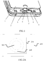
- FIG. 1 in the prior art, a groove (6) is opened on a housing of an electronic device, a fingerprint recognition module (5) is placed in the groove (6), and the groove (6) is stuffed with a waterproof adhesive layer, so that the entire fingerprint module of the electronic device is protected and isolated from other components of the electronic device.
- a structure of a mobile phone needs to be changed.
- US 2016/0171271 A1 discloses a fingerprint sensing device comprising a sensing chip arranged on a substrate with readout circuitry wherein bond wires are arranged between bond pads located on the sensing chip on the substrate to electrically connect the sensing chip to the readout circuitry, with a portion of the bond wire protruding above the chip.
- Embodiments of the present invention provide a fingerprint recognition module, to achieve waterproofing in the fingerprint recognition module, improve compatibility with mass production, and reduce adhesive dispensing.
- a fingerprint recognition module comprising:
- a groove (2051) is provided on an upper part of the wall plate (205), a boss (2011) is correspondingly provided on a lower part of the protective cover (201), and the boss (2011) fits the groove (2051).
- a notch (2052) is provided inside the upper opening of the wall plate (205), and a boss (2012) fitting the notch is provided on a lower part of the protective cover (201).
- an electronic device (700) including a fingerprint recognition according to claim 1 and a printed circuit board (701).
- a groove (2051) is provided on an upper part of the wall plate (205), a boss (2011) is correspondingly provided on a lower part of the protective cover (201), and the boss (2011) fits the groove (2051).
- a notch (2052) is provided inside the upper opening of the wall plate (205), and a boss (2012) fitting the notch is provided on a lower part of the protective cover (201).
- the fingerprint recognition sensor is encircled by the protective cover, the wall plate, and the lower cover, and electronic waterproof adhesive is provided in the seam, so that water is prevented from entering the fingerprint recognition sensor.
- the entire fingerprint module is integrated as a whole, so that waterproofing can be implemented by the fingerprint module, without a need to use a waterproofing design of another part of the electronic device to implement waterproofing. In this way, compatibility with mass production is improved, and adhesive dispensing is reduced.
- an embodiment of the present invention provides a waterproof fingerprint recognition module, including a protective cover 201, a fingerprint recognition sensor 202, a circuit connector 203, a wall plate 205, and a lower cover 206.
- the protective cover 201 is commonly made of a high modulus material such as glass, sapphire, and ceramic and is mainly configured to protect the fingerprint recognition sensor 202, so that a foreign object such as sweat or a hard object is prevented from damaging the fingerprint recognition sensor.
- the fingerprint recognition sensor 202 is configured to generate a fingerprint image after a finger touches the protective cover.
- a plurality of products may be available for selection of the fingerprint recognition sensor 202, for example, a 1268 fingerprint recognition chip from FPC or an 8268 chip from Goodix (Goddisk). This embodiment of the present invention imposes no limitation thereto.
- the circuit connector 203 is configured to electrically connect a printed circuit board of an electronic device to the fingerprint recognition sensor.
- the circuit connector may be a wire, a flexible circuit board (Flexible Printed Circuit, FPC), or the like.
- the wall plate 205 encircles the fingerprint recognition sensor 202 for one round to protect the fingerprint recognition sensor 202.
- the wall plate 205 may be made of a metal material.
- the lower cover 206 is usually made of a metal material. Both the fingerprint recognition sensor 202 and the wall plate 205 are fastened on the lower cover 206 to form a whole.
- the protective cover 201 is located over the wall plate 205, the wall plate 205 encircles the fingerprint recognition sensor 202, the protective cover 201 fully covers an upper opening of the wall plate 205, electronic waterproof adhesive is provided in a seam between the wall plate 205 and the protective cover 201, the lower cover 206 is located under the wall plate 205, and the lower cover 206 bonds with a lower part of the wall plate 205. If there is an opening on the lower part of the wall plate 205, the lower cover 206 fully covers the lower opening of the wall plate 205.
- “over” refers to a direction that a fingerprint sensing surface of the fingerprint recognition sensor 202 faces
- under refers to a direction opposite to the direction that the fingerprint sensing surface of the fingerprint recognition sensor 202 faces.
- the upper opening of the wall plate 205 may be in the shape of a circle, a rectangle, an oval, a runway, or another closed figure.
- the wall plate 205 may be in the shape of a hollow cylinder, a cone, or the like.
- a reinforcement plate 204 is provided under the fingerprint recognition sensor 202, and the reinforcement plate 204 supports the circuit connector 203.
- the lower cover 206 and the wall plate 205 are glued together by using electronic waterproof adhesive or are welded together.
- any one of the protective cover 201, the wall plate 205, the reinforcement plate 204, and the lower cover 206 may be molded integrally, or may be spliced by using at least two components. This embodiment of the present invention imposes no limitation thereto.
- the electronic waterproof adhesive is also referred to as electronic damp-proof paint or conformal coating.
- the electronic waterproof adhesive is a coating made of a special formula, and is configured to protect a circuit board and a related device from erosion in an environment, to improve and prolong a service life of the circuit board and the related device, thereby ensuring use security and reliability.
- the electronic waterproof adhesive may be classified into the following types in terms of chemical composition: Acrylic acid composition: Resistant to a high temperature of 130 degrees Celsius and a low temperature of minus 60 degrees Celsius, relatively hard after being cured, and has fine damp-proof, anti-corrosion, and salt spray resistance effects.
- Polyurethane composition Resistant to a high temperature of 130 degrees Celsius and a low temperature of minus 60 degrees Celsius, harder than acrylic acid after being cured, and has excellent weather resistance, damp-proof, anti-corrosion, and salt spray resistance effects.
- Organosilicon waterproof adhesive is a high-end product resistant to a high temperature of 200 degrees Celsius and a low temperature of minus 60 degrees Celsius, elastic after being cured, and has excellent damp-proof, anti-corrosion, and salt spray resistance effects.
- a type and an arranging method of the electronic waterproof adhesive are not limited in this embodiment of the present invention.
- the fingerprint recognition sensor is encircled by the protective cover, the wall plate, and the lower cover, and the electronic waterproof adhesive is provided in the seam, so that water is prevented from entering the fingerprint recognition sensor.
- the entire fingerprint module is integrated as a whole, so that waterproofing can be implemented by the fingerprint module, without a need to use a waterproofing design of another part of the electronic device to implement waterproofing.
- the protective cover 201 may fit the upper opening of the wall plate.
- a size and a shape of the protective cover are approximately the same as a size and a shape of the upper opening of the wall plate. In this way, an area of the protective cover is relatively small.
- the protective cover 201 may be greater than the upper opening of the wall plate 205. In this way, the protective cover fully covers the upper part of the wall plate, so that a water inflow path can be better cut off.
- a groove 2051 is provided on an upper part of the wall plate 205
- a boss 2011 is correspondingly provided on a lower part of the protective cover 201, and the boss fits the groove.
- a notch 2052 is provided inside the upper opening of the wall plate 205, and a boss 2012 fitting the notch is provided on a lower part of the protective cover 201.
- the bottom of the groove 2051 and the bottom of the notch 2052 may be flat surfaces, or may be U-shape, V-shape, W-shape, or other curved surfaces.
- the top of the boss 2011 may be a flat surface, or may be a U-shape, a V-shape, a W-shape, or another curved surface
- a fitting part between the boss 2012 and the notch 2052 may be a flat surface, or may be a U-shape, a V-shape, a W-shape, or another curved surface.
- This embodiment of the present invention imposes no limitation thereto.
- the groove, the notch, and the boss can better block a water inflow path and achieve a better waterproofing effect.
- a side opening 2053 is provided on a side face of the wall plate 205, the circuit connector 203 protrudes from the side opening 2053.
- the side opening 2053 is a possible water inlet, and therefore, waterproofing processing is required.
- the side opening 2053 is stuffed with waterproof adhesive, so that a waterproofing purpose is achieved.
- the side opening 2053 is blocked by an elastomer 207, and the elastomer 207 tightly fits (for example, through interference fitting) the side opening 2053, so that water seepage is prevented.
- the elastomer 207 may be made of an elastic material such as silica gel, rubber, a thermoplastic elastomer, modified polyurethane, and modified epoxy resin.
- the elastomer 207 may be a gasket, a washer, a cylinder fitting inside the wall plate 205, or a small piece of elastic material that fits the side opening 2053. This embodiment of the present invention imposes no limitation thereto.
- an embodiment of the present invention further provides an electronic device.
- the electronic device 700 includes the fingerprint recognition module disclosed in the foregoing embodiments and a printed circuit board (Printed Circuit Board, PCB) 701.
- a circuit connector 203 in the fingerprint recognition module is electrically connected to the PCB 701.
- a structure of the fingerprint recognition module has been described in detail in the foregoing embodiments. Details are not described herein again.
- the electronic device may be a mobile phone, a tablet computer, a wearable device, a GPS receiver, an in-vehicle electronic device.
- This embodiment of the present invention imposes no limitation thereto.
Landscapes
- Engineering & Computer Science (AREA)
- Signal Processing (AREA)
- Computer Hardware Design (AREA)
- Theoretical Computer Science (AREA)
- General Engineering & Computer Science (AREA)
- Human Computer Interaction (AREA)
- Physics & Mathematics (AREA)
- General Physics & Mathematics (AREA)
- Multimedia (AREA)
- Casings For Electric Apparatus (AREA)
- Telephone Set Structure (AREA)
Description
- The present invention relates to the field of electronic technologies, and in particular, to a waterproof fingerprint recognition module and an electronic device.
- Currently, a fingerprint recognition function is more popular in a handheld electronic device such as a mobile phone or a tablet computer. With a fingerprint recognition module mounted on an electronic device, the electronic device can recognize a user's fingerprint, thereby improving security of the electronic device. However, because existing handheld electronic devices favor light and thin designs, a waterproof design for the fingerprint recognition module becomes a difficulty. As shown in
FIG. 1 , in the prior art, a groove (6) is opened on a housing of an electronic device, a fingerprint recognition module (5) is placed in the groove (6), and the groove (6) is stuffed with a waterproof adhesive layer, so that the entire fingerprint module of the electronic device is protected and isolated from other components of the electronic device. However, in this design solution, a structure of a mobile phone needs to be changed. If a size of the fingerprint module changes, the structure of the mobile phone needs to be designed again. Consequently, compatibility with mass production is lacking, a machining process is complex, adhesive needs to be dispensed on a plurality of positions, space for the fingerprint module is enlarged, and the mobile phone cannot be thin or light. -
US 2016/0171271 A1 discloses a fingerprint sensing device comprising a sensing chip arranged on a substrate with readout circuitry wherein bond wires are arranged between bond pads located on the sensing chip on the substrate to electrically connect the sensing chip to the readout circuitry, with a portion of the bond wire protruding above the chip. - Another prior art fingerprint sensing device is disclosed by
US 2013/259329 A1 . - Embodiments of the present invention provide a fingerprint recognition module, to achieve waterproofing in the fingerprint recognition module, improve compatibility with mass production, and reduce adhesive dispensing.
- As defined in
claim 1, it is provided a fingerprint recognition module comprising: - a protective cover (201), a fingerprint recognition sensor (202), a circuit connector (203), a wall plate (205), and a lower cover (206), where
- the protective cover (201) is located over the wall plate (205), the wall plate (205) encircles the fingerprint recognition sensor (202), the protective cover (201) fully covers an upper opening of the wall plate (205), electronic waterproof adhesive is provided in a seam between the wall plate (205) and the protective cover (201), the lower cover (206) is located under the wall plate (205), the lower cover (206) bonds with a lower part of the wall plate (205), and the circuit connector (203) is electrically connected to the fingerprint recognition sensor (202); where
- "over" refers to a direction that a fingerprint sensing surface of the fingerprint recognition sensor (202) faces, and "under" refers to a direction opposite to the direction that the fingerprint sensing surface of the fingerprint recognition sensor (202) faces,
- characterized in that:
a side opening (2053) is provided on a side face of the wall plate (205), the circuit connector (203) protrudes from the side opening (2053), and the side opening (2053) is stuffed with waterproof adhesive. - Optionally, a groove (2051) is provided on an upper part of the wall plate (205), a boss (2011) is correspondingly provided on a lower part of the protective cover (201), and the boss (2011) fits the groove (2051).
- Optionally, a notch (2052) is provided inside the upper opening of the wall plate (205), and a boss (2012) fitting the notch is provided on a lower part of the protective cover (201).
- According to another aspect of the present invention, an electronic device (700) is further provided, including a fingerprint recognition according to
claim 1 and a printed circuit board (701). - Optionally, a groove (2051) is provided on an upper part of the wall plate (205), a boss (2011) is correspondingly provided on a lower part of the protective cover (201), and the boss (2011) fits the groove (2051).
- Optionally, a notch (2052) is provided inside the upper opening of the wall plate (205), and a boss (2012) fitting the notch is provided on a lower part of the protective cover (201).
- According to the fingerprint recognition module and the electronic device that are provided in the foregoing embodiments, the fingerprint recognition sensor is encircled by the protective cover, the wall plate, and the lower cover, and electronic waterproof adhesive is provided in the seam, so that water is prevented from entering the fingerprint recognition sensor. In addition, the entire fingerprint module is integrated as a whole, so that waterproofing can be implemented by the fingerprint module, without a need to use a waterproofing design of another part of the electronic device to implement waterproofing. In this way, compatibility with mass production is improved, and adhesive dispensing is reduced.
-
-
FIG. 1 is a structural diagram of waterproof encircling for a fingerprint recognition module in the prior art; -
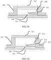
FIG. 2A is a top view of a fingerprint recognition module according to an embodiment of the present invention; -
FIG. 2B is a side cross-sectional view of a fingerprint recognition module according to an embodiment of the present invention; -
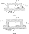
FIG. 3A is a side cross-sectional view of a fingerprint recognition module according to another embodiment of the present invention; -
FIG. 3B is a side cross-sectional view of a fingerprint recognition module according to still another embodiment of the present invention; -
FIG. 3C is a side cross-sectional view of a fingerprint recognition module according to yet another embodiment of the present invention; -
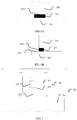
FIG. 3D is a side cross-sectional view of a fingerprint recognition module according to still yet embodiment of the present invention; -
FIG. 4A is a partial side cross-sectional view of a boss of a protective cover and a notch of a wall plate inFIG. 3C ; -
FIG. 4B is a partial side cross-sectional view of a boss of a protective cover and a groove of a wall plate inFIG. 3D ; -
FIG. 5 is an exploded view of a fingerprint recognition module according to an embodiment of the present invention; -
FIG. 6A is a partial elevational view of a side opening of a wall plate according to an embodiment of the present invention; -
FIG. 6B is a partial side view of a side opening of a wall plate according to an embodiment of the present invention; and -
FIG. 7 is a schematic structural diagram of an electronic device according to an embodiment of the present invention. - Explanation of reference numerals:
- 201: Protective cover; 202: Fingerprint recognition sensor; 203: Circuit connector;
- 204: Reinforcement plate; 205: Wall plate; 206: Lower cover;
- 2051: Groove on an upper part of the wall plate; 2052: Notch inside the upper part of the wall plate;
- 2053: Side opening of the wall plate; 2011 and 2012: Bosses on a lower part of the protective cover;
- 207: Elastomer; 700: Electronic device; 701: Printed circuit board of the electronic device.
- Specific implementations of the present invention are described in detail below with reference to the accompanying drawings.
- As shown in
FIG. 2A ,FIG. 2B , andFIG. 5 , an embodiment of the present invention provides a waterproof fingerprint recognition module, including aprotective cover 201, afingerprint recognition sensor 202, acircuit connector 203, awall plate 205, and alower cover 206. - The
protective cover 201 is commonly made of a high modulus material such as glass, sapphire, and ceramic and is mainly configured to protect thefingerprint recognition sensor 202, so that a foreign object such as sweat or a hard object is prevented from damaging the fingerprint recognition sensor. - The
fingerprint recognition sensor 202 is configured to generate a fingerprint image after a finger touches the protective cover. A plurality of products may be available for selection of thefingerprint recognition sensor 202, for example, a 1268 fingerprint recognition chip from FPC or an 8268 chip from Goodix (Goddisk). This embodiment of the present invention imposes no limitation thereto. - The
circuit connector 203 is configured to electrically connect a printed circuit board of an electronic device to the fingerprint recognition sensor. The circuit connector may be a wire, a flexible circuit board (Flexible Printed Circuit, FPC), or the like. - The
wall plate 205 encircles thefingerprint recognition sensor 202 for one round to protect thefingerprint recognition sensor 202. Thewall plate 205 may be made of a metal material. - The
lower cover 206 is usually made of a metal material. Both thefingerprint recognition sensor 202 and thewall plate 205 are fastened on thelower cover 206 to form a whole. - The
protective cover 201 is located over thewall plate 205, thewall plate 205 encircles thefingerprint recognition sensor 202, theprotective cover 201 fully covers an upper opening of thewall plate 205, electronic waterproof adhesive is provided in a seam between thewall plate 205 and theprotective cover 201, thelower cover 206 is located under thewall plate 205, and thelower cover 206 bonds with a lower part of thewall plate 205. If there is an opening on the lower part of thewall plate 205, thelower cover 206 fully covers the lower opening of thewall plate 205. Herein, "over" refers to a direction that a fingerprint sensing surface of thefingerprint recognition sensor 202 faces, and "under" refers to a direction opposite to the direction that the fingerprint sensing surface of thefingerprint recognition sensor 202 faces. - The upper opening of the
wall plate 205 may be in the shape of a circle, a rectangle, an oval, a runway, or another closed figure. Thewall plate 205 may be in the shape of a hollow cylinder, a cone, or the like. - Optionally, a
reinforcement plate 204 is provided under thefingerprint recognition sensor 202, and thereinforcement plate 204 supports thecircuit connector 203. - The
lower cover 206 and thewall plate 205 are glued together by using electronic waterproof adhesive or are welded together. - Any one of the
protective cover 201, thewall plate 205, thereinforcement plate 204, and thelower cover 206 may be molded integrally, or may be spliced by using at least two components. This embodiment of the present invention imposes no limitation thereto. - The electronic waterproof adhesive is also referred to as electronic damp-proof paint or conformal coating. The electronic waterproof adhesive is a coating made of a special formula, and is configured to protect a circuit board and a related device from erosion in an environment, to improve and prolong a service life of the circuit board and the related device, thereby ensuring use security and reliability. The electronic waterproof adhesive may be classified into the following types in terms of chemical composition:
Acrylic acid composition: Resistant to a high temperature of 130 degrees Celsius and a low temperature of minus 60 degrees Celsius, relatively hard after being cured, and has fine damp-proof, anti-corrosion, and salt spray resistance effects. - Polyurethane composition: Resistant to a high temperature of 130 degrees Celsius and a low temperature of minus 60 degrees Celsius, harder than acrylic acid after being cured, and has excellent weather resistance, damp-proof, anti-corrosion, and salt spray resistance effects.
- Organosilicon composition: Organosilicon waterproof adhesive is a high-end product resistant to a high temperature of 200 degrees Celsius and a low temperature of minus 60 degrees Celsius, elastic after being cured, and has excellent damp-proof, anti-corrosion, and salt spray resistance effects.
- There are mainly four methods for arranging the electronic waterproof adhesive:
- 1. Brush coating: is commonly used and can produce an excellent coating effect on a smooth surface.
- 2. Spray coating: A tank-type product can be conveniently applied in repair and small-scale production, and a spray gun is suitable for mass production. However, these two spray coating manners have a relatively high requirement for operation accuracy and may produce a shadow (a place that is on a lower part of an element and that is not covered by waterproof adhesive).
- 3. Dip coating: Dip coating can ensure full coating and does not cause a material waste that is caused due to excessive spray coating.
- 4. Selective coating: The coating is accurate without a material waste, is suitable for large-scale coating, but has a relatively high requirement for a coating device.
- A type and an arranging method of the electronic waterproof adhesive are not limited in this embodiment of the present invention.
- According to the waterproof fingerprint recognition module provided in the foregoing embodiment, the fingerprint recognition sensor is encircled by the protective cover, the wall plate, and the lower cover, and the electronic waterproof adhesive is provided in the seam, so that water is prevented from entering the fingerprint recognition sensor. In addition, the entire fingerprint module is integrated as a whole, so that waterproofing can be implemented by the fingerprint module, without a need to use a waterproofing design of another part of the electronic device to implement waterproofing.
- As shown in
FIG. 2B , theprotective cover 201 may fit the upper opening of the wall plate. In other words, a size and a shape of the protective cover are approximately the same as a size and a shape of the upper opening of the wall plate. In this way, an area of the protective cover is relatively small. - Alternatively, as shown in
FIG. 3A , theprotective cover 201 may be greater than the upper opening of thewall plate 205. In this way, the protective cover fully covers the upper part of the wall plate, so that a water inflow path can be better cut off. Preferably, as shown inFIG. 3D andFIG. 4B , agroove 2051 is provided on an upper part of thewall plate 205, aboss 2011 is correspondingly provided on a lower part of theprotective cover 201, and the boss fits the groove. Alternatively, as shown inFIG. 3B, FIG. 3C , andFIG. 4A , anotch 2052 is provided inside the upper opening of thewall plate 205, and aboss 2012 fitting the notch is provided on a lower part of theprotective cover 201. The bottom of thegroove 2051 and the bottom of thenotch 2052 may be flat surfaces, or may be U-shape, V-shape, W-shape, or other curved surfaces. Correspondingly, the top of theboss 2011 may be a flat surface, or may be a U-shape, a V-shape, a W-shape, or another curved surface, and a fitting part between theboss 2012 and thenotch 2052 may be a flat surface, or may be a U-shape, a V-shape, a W-shape, or another curved surface. This embodiment of the present invention imposes no limitation thereto. The groove, the notch, and the boss can better block a water inflow path and achieve a better waterproofing effect. - As shown in
FIG. 5 , in an embodiment of the present invention, aside opening 2053 is provided on a side face of thewall plate 205, thecircuit connector 203 protrudes from theside opening 2053. Theside opening 2053 is a possible water inlet, and therefore, waterproofing processing is required. In an embodiment, theside opening 2053 is stuffed with waterproof adhesive, so that a waterproofing purpose is achieved. As shown inFIG. 5 ,FIG. 6A, and FIG. 6B , in another embodiment, theside opening 2053 is blocked by anelastomer 207, and theelastomer 207 tightly fits (for example, through interference fitting) theside opening 2053, so that water seepage is prevented. Theelastomer 207 may be made of an elastic material such as silica gel, rubber, a thermoplastic elastomer, modified polyurethane, and modified epoxy resin. Theelastomer 207 may be a gasket, a washer, a cylinder fitting inside thewall plate 205, or a small piece of elastic material that fits theside opening 2053. This embodiment of the present invention imposes no limitation thereto. - As shown in
FIG. 7 , an embodiment of the present invention further provides an electronic device. The electronic device 700 includes the fingerprint recognition module disclosed in the foregoing embodiments and a printed circuit board (Printed Circuit Board, PCB) 701. Acircuit connector 203 in the fingerprint recognition module is electrically connected to thePCB 701. A structure of the fingerprint recognition module has been described in detail in the foregoing embodiments. Details are not described herein again. - The electronic device may be a mobile phone, a tablet computer, a wearable device, a GPS receiver, an in-vehicle electronic device. This embodiment of the present invention imposes no limitation thereto.
- The foregoing embodiments are merely example embodiments of the present invention, but are not intended to limit the protection scope of the present invention that is only defined by the appended claims.
Claims (6)
- A fingerprint recognition module, comprising:a protective cover (201), a fingerprint recognition sensor (202), a circuit connector (203), a wall plate (205), and a lower cover (206), whereinthe protective cover (201) is located over the wall plate (205), the wall plate (205) encircles the fingerprint recognition sensor (202), the protective cover (201) fully covers an upper opening of the wall plate (205), electronic waterproof adhesive is provided in a seam between the wall plate (205) and the protective cover (201), the lower cover (206) is located under the wall plate (205), the lower cover (206) bonds with a lower part of the wall plate (205), and the circuit connector (203) is electrically connected to the fingerprint recognition sensor (202); wherein"over" refers to a direction that a fingerprint sensing surface of the fingerprint recognition sensor (202) faces, and "under" refers to a direction opposite to the direction that the fingerprint sensing surface of the fingerprint recognition sensor (202) faces,characterized in that:a side opening (2053) is provided on a side face of the wall plate (205), the circuit connector (203) protrudes from the side opening (2053), andthe side opening (2053) is stuffed with waterproof adhesive, orthe fingerprint recognition module further comprises an elastomer (207), and the elastomer (207) tightly fits the side opening (2053).
- The fingerprint recognition module according to claim 1, wherein a groove (2051) is provided on an upper part of the wall plate (205), a boss (2011) is correspondingly provided on a lower part of the protective cover (201), and the boss (2011) fits the groove (2051).
- The fingerprint recognition module according to claim 1, wherein a notch (2052) is provided inside the upper opening of the wall plate (205), and a boss (2012) fitting the notch is provided on a lower part of the protective cover (201).
- An electronic device (700), comprising a fingerprint recognition module according to claim 1 and a printed circuit board (701).
- The electronic device (700) according to claim 4, wherein a groove (2051) is provided on an upper part of the wall plate (205), a boss (2011) is correspondingly provided on a lower part of the protective cover (201), and the boss (2011) fits the groove (2051).
- The electronic device (700) according to claim 4, wherein a notch (2052) is provided inside the upper opening of the wall plate (205), and a boss (2012) fitting the notch is provided on a lower part of the protective cover (201).
Applications Claiming Priority (1)
| Application Number | Priority Date | Filing Date | Title |
|---|---|---|---|
| PCT/CN2016/088182 WO2018000429A1 (en) | 2016-07-01 | 2016-07-01 | Waterproof fingerprint recognition module and electronic device |
Publications (3)
| Publication Number | Publication Date |
|---|---|
| EP3413238A1 EP3413238A1 (en) | 2018-12-12 |
| EP3413238A4 EP3413238A4 (en) | 2019-04-17 |
| EP3413238B1 true EP3413238B1 (en) | 2020-11-11 |
Family
ID=60785062
Family Applications (1)
| Application Number | Title | Priority Date | Filing Date |
|---|---|---|---|
| EP16906828.5A Active EP3413238B1 (en) | 2016-07-01 | 2016-07-01 | Waterproof fingerprint recognition module and electronic device |
Country Status (4)
| Country | Link |
|---|---|
| US (1) | US10536568B2 (en) |
| EP (1) | EP3413238B1 (en) |
| CN (1) | CN109416746B (en) |
| WO (1) | WO2018000429A1 (en) |
Cited By (1)
| Publication number | Priority date | Publication date | Assignee | Title |
|---|---|---|---|---|
| CN114371786A (en) * | 2021-11-26 | 2022-04-19 | 国网辽宁省电力有限公司大连供电公司 | Computer equipment safety device |
Families Citing this family (6)
| Publication number | Priority date | Publication date | Assignee | Title |
|---|---|---|---|---|
| CN106066673B (en) * | 2016-07-26 | 2018-01-19 | 广东欧珀移动通信有限公司 | Mobile terminal, housing assembly, display assembly and assembly method thereof |
| WO2018187963A1 (en) * | 2017-04-12 | 2018-10-18 | 深圳市汇顶科技股份有限公司 | Optical fingerprint sensor and packaging method therefor |
| TWI663551B (en) * | 2018-03-23 | 2019-06-21 | 致伸科技股份有限公司 | Method of assembling fingerprint identification module |
| CN108667974A (en) * | 2018-03-27 | 2018-10-16 | 合肥龙图腾信息技术有限公司 | A kind of face tracking system and method based on smart mobile phone support |
| CN115457607A (en) * | 2019-08-19 | 2022-12-09 | 华为技术有限公司 | Fingerprint identification device and electronic equipment |
| KR102958348B1 (en) * | 2020-06-23 | 2026-04-30 | 삼성디스플레이 주식회사 | Display device |
Family Cites Families (32)
| Publication number | Priority date | Publication date | Assignee | Title |
|---|---|---|---|---|
| JP4201476B2 (en) * | 2000-10-13 | 2008-12-24 | 富士通株式会社 | Fingerprint recognition device |
| WO2004093005A1 (en) * | 2003-04-15 | 2004-10-28 | Fujitsu Limited | Information processor |
| JP5125810B2 (en) * | 2008-06-27 | 2013-01-23 | 富士通株式会社 | Electronics |
| US8736001B2 (en) * | 2010-06-18 | 2014-05-27 | Authentec, Inc. | Finger sensor including encapsulating layer over sensing area and related methods |
| CN102096815B (en) * | 2011-01-20 | 2013-12-11 | 成都方程式电子有限公司 | Optical fingerprint acquisition instrument without keystone distortions |
| JP2013070271A (en) * | 2011-09-22 | 2013-04-18 | Fujitsu Ltd | Electronic apparatus |
| JP5799814B2 (en) * | 2012-01-10 | 2015-10-28 | 富士通株式会社 | Electronics |
| CN202523077U (en) | 2012-03-27 | 2012-11-07 | 成素华 | Mounting sleeve structure used for placing fingerprint identification module |
| US9152838B2 (en) * | 2012-03-29 | 2015-10-06 | Synaptics Incorporated | Fingerprint sensor packagings and methods |
| JP6011012B2 (en) * | 2012-05-11 | 2016-10-19 | 富士通株式会社 | Waterproof switch and electronic equipment |
| US20150201723A1 (en) * | 2013-02-01 | 2015-07-23 | Treefrog Developments, Inc. | Encasements for an electronic device having a biometric scanner |
| JP2014160610A (en) * | 2013-02-20 | 2014-09-04 | Fujitsu Mobile Communications Ltd | Water stop member for cable insertion hole and electronic device with the water stop member |
| US9254633B2 (en) * | 2013-07-09 | 2016-02-09 | Apple Inc. | Environmental seal maximizing sensor space beneath a button positioned in trim |
| US10534900B2 (en) * | 2014-02-21 | 2020-01-14 | Samsung Electronics Co., Ltd. | Electronic device |
| CN104051366B (en) | 2014-07-01 | 2017-06-20 | 苏州晶方半导体科技股份有限公司 | Fingerprint recognition chip-packaging structure and method for packing |
| CN104051367A (en) | 2014-07-01 | 2014-09-17 | 苏州晶方半导体科技股份有限公司 | Packaging structure and packaging method for fingerprint recognition chip |
| US9886613B2 (en) * | 2014-07-07 | 2018-02-06 | Shenzhen GOODIX Technology Co., Ltd. | Integration of touch screen and fingerprint sensor assembly |
| KR102206242B1 (en) * | 2014-08-04 | 2021-01-22 | 엘지전자 주식회사 | Mobile terminal |
| CN104182737B (en) * | 2014-08-26 | 2017-09-15 | 南昌欧菲生物识别技术有限公司 | Fingerprint Identification sensor encapsulating structure and method for packing |
| CN104201116B (en) | 2014-09-12 | 2018-04-20 | 苏州晶方半导体科技股份有限公司 | Fingerprint recognition chip packaging method and encapsulating structure |
| WO2016093669A1 (en) * | 2014-12-11 | 2016-06-16 | 크루셜텍(주) | Fingerprint sensor module assembly integrated with cover window for electronic device |
| US9576177B2 (en) * | 2014-12-11 | 2017-02-21 | Fingerprint Cards Ab | Fingerprint sensing device |
| CN204288244U (en) * | 2014-12-23 | 2015-04-22 | 广东光阵光电科技有限公司 | A waterproof fingerprint identification device |
| CN204302997U (en) * | 2014-12-26 | 2015-04-29 | 上海晨兴希姆通电子科技有限公司 | For the waterproof fingerprint identification device of mobile phone |
| KR102302361B1 (en) * | 2014-12-31 | 2021-09-15 | 삼성전자 주식회사 | System and method for matching between application and device |
| US9959444B2 (en) * | 2015-09-02 | 2018-05-01 | Synaptics Incorporated | Fingerprint sensor under thin face-sheet with aperture layer |
| CN205068302U (en) * | 2015-09-06 | 2016-03-02 | 范海旭 | Multi -functional keyboard |
| US10402616B2 (en) * | 2015-10-21 | 2019-09-03 | Motorola Mobility Llc | Fingerprint sensor with proximity detection, and corresponding devices, systems, and methods |
| CN105512634B (en) * | 2015-12-14 | 2019-01-15 | 联想(北京)有限公司 | A kind of sensing device and a kind of electronic equipment |
| CN205302331U (en) * | 2016-01-14 | 2016-06-08 | 深圳市汇顶科技股份有限公司 | Biological detection device |
| CN105704267B (en) * | 2016-01-27 | 2019-03-29 | Oppo广东移动通信有限公司 | mobile terminal |
| GB2552131A (en) * | 2016-05-06 | 2018-01-17 | Zwipe As | Electrical validation of a purported finger |
-
2016
- 2016-07-01 WO PCT/CN2016/088182 patent/WO2018000429A1/en not_active Ceased
- 2016-07-01 EP EP16906828.5A patent/EP3413238B1/en active Active
- 2016-07-01 US US16/313,371 patent/US10536568B2/en active Active
- 2016-07-01 CN CN201680087338.2A patent/CN109416746B/en active Active
Non-Patent Citations (1)
| Title |
|---|
| None * |
Cited By (2)
| Publication number | Priority date | Publication date | Assignee | Title |
|---|---|---|---|---|
| CN114371786A (en) * | 2021-11-26 | 2022-04-19 | 国网辽宁省电力有限公司大连供电公司 | Computer equipment safety device |
| CN114371786B (en) * | 2021-11-26 | 2024-04-12 | 国网辽宁省电力有限公司大连供电公司 | Computer equipment safety device |
Also Published As
| Publication number | Publication date |
|---|---|
| WO2018000429A1 (en) | 2018-01-04 |
| EP3413238A4 (en) | 2019-04-17 |
| CN109416746A (en) | 2019-03-01 |
| US20190166241A1 (en) | 2019-05-30 |
| EP3413238A1 (en) | 2018-12-12 |
| CN109416746B (en) | 2022-04-05 |
| US10536568B2 (en) | 2020-01-14 |
Similar Documents
| Publication | Publication Date | Title |
|---|---|---|
| US10536568B2 (en) | Waterproof fingerprint recognition module and electronic device | |
| CN205405465U (en) | Touch -control display screen with fingerprint identification function | |
| EP3285464B1 (en) | Method for manufacturing input assembly, input assembly and terminal | |
| US10264336B2 (en) | Electronic device and conductive structure | |
| CN206948452U (en) | Portable electronic device and its image capture module and carrying component | |
| CN205656637U (en) | Fingerprint identification subassembly, mobile terminal's apron subassembly and mobile terminal | |
| TWI595573B (en) | Fingerprint identification device and touch display device having same | |
| CN109145721B (en) | Terminal device | |
| US20150198551A1 (en) | Gas sensor package | |
| KR20050061384A (en) | Portable electronic appliance including a pressure sensor | |
| CN205427873U (en) | Fingerprint sensing unit and fingerprint sensing module | |
| US20200320268A1 (en) | Fingerprint Module And Electronic Device | |
| CN206133504U (en) | Input components and terminals | |
| CN107613704A (en) | A kind of fingerprint module and mobile terminal | |
| CN107979669B (en) | Touch fingerprint assembly for smart phone | |
| WO2019071603A1 (en) | Structure of electronic device and electronic device | |
| KR20160055573A (en) | Antenna module and electronic device including the same | |
| CN107896259A (en) | Fingerprint recognition module and its assemble method and electronic installation | |
| CN107018216A (en) | Decorative ring structure and manufacturing method thereof, cover assembly and electronic device | |
| KR20190143584A (en) | Optical sensor package | |
| CN206178885U (en) | Fingerprint module and mobile terminal | |
| WO2018149252A1 (en) | Fingerprint identification component and terminal | |
| EP3288245B1 (en) | Fingerprint sensor and terminal using the same | |
| CN215068271U (en) | A narrow strip fingerprint chip, side fingerprint chip module and electronic equipment | |
| CN211236920U (en) | Fingerprint identification chip package module, fingerprint identification module and electronic equipment |
Legal Events
| Date | Code | Title | Description |
|---|---|---|---|
| STAA | Information on the status of an ep patent application or granted ep patent |
Free format text: STATUS: THE INTERNATIONAL PUBLICATION HAS BEEN MADE |
|
| PUAI | Public reference made under article 153(3) epc to a published international application that has entered the european phase |
Free format text: ORIGINAL CODE: 0009012 |
|
| STAA | Information on the status of an ep patent application or granted ep patent |
Free format text: STATUS: REQUEST FOR EXAMINATION WAS MADE |
|
| 17P | Request for examination filed |
Effective date: 20180907 |
|
| AK | Designated contracting states |
Kind code of ref document: A1 Designated state(s): AL AT BE BG CH CY CZ DE DK EE ES FI FR GB GR HR HU IE IS IT LI LT LU LV MC MK MT NL NO PL PT RO RS SE SI SK SM TR |
|
| AX | Request for extension of the european patent |
Extension state: BA ME |
|
| REG | Reference to a national code |
Ref country code: DE Ref legal event code: R079 Ref document number: 602016047894 Country of ref document: DE Free format text: PREVIOUS MAIN CLASS: G06K0009620000 Ipc: H04M0001020000 |
|
| A4 | Supplementary search report drawn up and despatched |
Effective date: 20190315 |
|
| RIC1 | Information provided on ipc code assigned before grant |
Ipc: H04M 1/02 20060101AFI20190311BHEP Ipc: H04M 1/18 20060101ALI20190311BHEP |
|
| DAV | Request for validation of the european patent (deleted) | ||
| DAX | Request for extension of the european patent (deleted) | ||
| STAA | Information on the status of an ep patent application or granted ep patent |
Free format text: STATUS: EXAMINATION IS IN PROGRESS |
|
| 17Q | First examination report despatched |
Effective date: 20191127 |
|
| GRAP | Despatch of communication of intention to grant a patent |
Free format text: ORIGINAL CODE: EPIDOSNIGR1 |
|
| STAA | Information on the status of an ep patent application or granted ep patent |
Free format text: STATUS: GRANT OF PATENT IS INTENDED |
|
| INTG | Intention to grant announced |
Effective date: 20200514 |
|
| GRAS | Grant fee paid |
Free format text: ORIGINAL CODE: EPIDOSNIGR3 |
|
| GRAA | (expected) grant |
Free format text: ORIGINAL CODE: 0009210 |
|
| STAA | Information on the status of an ep patent application or granted ep patent |
Free format text: STATUS: THE PATENT HAS BEEN GRANTED |
|
| AK | Designated contracting states |
Kind code of ref document: B1 Designated state(s): AL AT BE BG CH CY CZ DE DK EE ES FI FR GB GR HR HU IE IS IT LI LT LU LV MC MK MT NL NO PL PT RO RS SE SI SK SM TR |
|
| REG | Reference to a national code |
Ref country code: GB Ref legal event code: FG4D |
|
| REG | Reference to a national code |
Ref country code: CH Ref legal event code: EP |
|
| REG | Reference to a national code |
Ref country code: AT Ref legal event code: REF Ref document number: 1334543 Country of ref document: AT Kind code of ref document: T Effective date: 20201115 |
|
| REG | Reference to a national code |
Ref country code: DE Ref legal event code: R096 Ref document number: 602016047894 Country of ref document: DE |
|
| REG | Reference to a national code |
Ref country code: IE Ref legal event code: FG4D |
|
| REG | Reference to a national code |
Ref country code: NL Ref legal event code: FP |
|
| REG | Reference to a national code |
Ref country code: AT Ref legal event code: MK05 Ref document number: 1334543 Country of ref document: AT Kind code of ref document: T Effective date: 20201111 |
|
| PG25 | Lapsed in a contracting state [announced via postgrant information from national office to epo] |
Ref country code: NO Free format text: LAPSE BECAUSE OF FAILURE TO SUBMIT A TRANSLATION OF THE DESCRIPTION OR TO PAY THE FEE WITHIN THE PRESCRIBED TIME-LIMIT Effective date: 20210211 Ref country code: RS Free format text: LAPSE BECAUSE OF FAILURE TO SUBMIT A TRANSLATION OF THE DESCRIPTION OR TO PAY THE FEE WITHIN THE PRESCRIBED TIME-LIMIT Effective date: 20201111 Ref country code: PT Free format text: LAPSE BECAUSE OF FAILURE TO SUBMIT A TRANSLATION OF THE DESCRIPTION OR TO PAY THE FEE WITHIN THE PRESCRIBED TIME-LIMIT Effective date: 20210311 Ref country code: FI Free format text: LAPSE BECAUSE OF FAILURE TO SUBMIT A TRANSLATION OF THE DESCRIPTION OR TO PAY THE FEE WITHIN THE PRESCRIBED TIME-LIMIT Effective date: 20201111 Ref country code: GR Free format text: LAPSE BECAUSE OF FAILURE TO SUBMIT A TRANSLATION OF THE DESCRIPTION OR TO PAY THE FEE WITHIN THE PRESCRIBED TIME-LIMIT Effective date: 20210212 |
|
| PG25 | Lapsed in a contracting state [announced via postgrant information from national office to epo] |
Ref country code: LV Free format text: LAPSE BECAUSE OF FAILURE TO SUBMIT A TRANSLATION OF THE DESCRIPTION OR TO PAY THE FEE WITHIN THE PRESCRIBED TIME-LIMIT Effective date: 20201111 Ref country code: PL Free format text: LAPSE BECAUSE OF FAILURE TO SUBMIT A TRANSLATION OF THE DESCRIPTION OR TO PAY THE FEE WITHIN THE PRESCRIBED TIME-LIMIT Effective date: 20201111 Ref country code: IS Free format text: LAPSE BECAUSE OF FAILURE TO SUBMIT A TRANSLATION OF THE DESCRIPTION OR TO PAY THE FEE WITHIN THE PRESCRIBED TIME-LIMIT Effective date: 20210311 Ref country code: BG Free format text: LAPSE BECAUSE OF FAILURE TO SUBMIT A TRANSLATION OF THE DESCRIPTION OR TO PAY THE FEE WITHIN THE PRESCRIBED TIME-LIMIT Effective date: 20210211 Ref country code: AT Free format text: LAPSE BECAUSE OF FAILURE TO SUBMIT A TRANSLATION OF THE DESCRIPTION OR TO PAY THE FEE WITHIN THE PRESCRIBED TIME-LIMIT Effective date: 20201111 Ref country code: SE Free format text: LAPSE BECAUSE OF FAILURE TO SUBMIT A TRANSLATION OF THE DESCRIPTION OR TO PAY THE FEE WITHIN THE PRESCRIBED TIME-LIMIT Effective date: 20201111 |
|
| REG | Reference to a national code |
Ref country code: LT Ref legal event code: MG9D |
|
| PG25 | Lapsed in a contracting state [announced via postgrant information from national office to epo] |
Ref country code: HR Free format text: LAPSE BECAUSE OF FAILURE TO SUBMIT A TRANSLATION OF THE DESCRIPTION OR TO PAY THE FEE WITHIN THE PRESCRIBED TIME-LIMIT Effective date: 20201111 |
|
| PG25 | Lapsed in a contracting state [announced via postgrant information from national office to epo] |
Ref country code: EE Free format text: LAPSE BECAUSE OF FAILURE TO SUBMIT A TRANSLATION OF THE DESCRIPTION OR TO PAY THE FEE WITHIN THE PRESCRIBED TIME-LIMIT Effective date: 20201111 Ref country code: CZ Free format text: LAPSE BECAUSE OF FAILURE TO SUBMIT A TRANSLATION OF THE DESCRIPTION OR TO PAY THE FEE WITHIN THE PRESCRIBED TIME-LIMIT Effective date: 20201111 Ref country code: SM Free format text: LAPSE BECAUSE OF FAILURE TO SUBMIT A TRANSLATION OF THE DESCRIPTION OR TO PAY THE FEE WITHIN THE PRESCRIBED TIME-LIMIT Effective date: 20201111 Ref country code: LT Free format text: LAPSE BECAUSE OF FAILURE TO SUBMIT A TRANSLATION OF THE DESCRIPTION OR TO PAY THE FEE WITHIN THE PRESCRIBED TIME-LIMIT Effective date: 20201111 Ref country code: SK Free format text: LAPSE BECAUSE OF FAILURE TO SUBMIT A TRANSLATION OF THE DESCRIPTION OR TO PAY THE FEE WITHIN THE PRESCRIBED TIME-LIMIT Effective date: 20201111 Ref country code: RO Free format text: LAPSE BECAUSE OF FAILURE TO SUBMIT A TRANSLATION OF THE DESCRIPTION OR TO PAY THE FEE WITHIN THE PRESCRIBED TIME-LIMIT Effective date: 20201111 |
|
| REG | Reference to a national code |
Ref country code: DE Ref legal event code: R097 Ref document number: 602016047894 Country of ref document: DE |
|
| PG25 | Lapsed in a contracting state [announced via postgrant information from national office to epo] |
Ref country code: DK Free format text: LAPSE BECAUSE OF FAILURE TO SUBMIT A TRANSLATION OF THE DESCRIPTION OR TO PAY THE FEE WITHIN THE PRESCRIBED TIME-LIMIT Effective date: 20201111 |
|
| PLBE | No opposition filed within time limit |
Free format text: ORIGINAL CODE: 0009261 |
|
| STAA | Information on the status of an ep patent application or granted ep patent |
Free format text: STATUS: NO OPPOSITION FILED WITHIN TIME LIMIT |
|
| 26N | No opposition filed |
Effective date: 20210812 |
|
| PG25 | Lapsed in a contracting state [announced via postgrant information from national office to epo] |
Ref country code: AL Free format text: LAPSE BECAUSE OF FAILURE TO SUBMIT A TRANSLATION OF THE DESCRIPTION OR TO PAY THE FEE WITHIN THE PRESCRIBED TIME-LIMIT Effective date: 20201111 Ref country code: IT Free format text: LAPSE BECAUSE OF FAILURE TO SUBMIT A TRANSLATION OF THE DESCRIPTION OR TO PAY THE FEE WITHIN THE PRESCRIBED TIME-LIMIT Effective date: 20201111 |
|
| PG25 | Lapsed in a contracting state [announced via postgrant information from national office to epo] |
Ref country code: SI Free format text: LAPSE BECAUSE OF FAILURE TO SUBMIT A TRANSLATION OF THE DESCRIPTION OR TO PAY THE FEE WITHIN THE PRESCRIBED TIME-LIMIT Effective date: 20201111 |
|
| PG25 | Lapsed in a contracting state [announced via postgrant information from national office to epo] |
Ref country code: ES Free format text: LAPSE BECAUSE OF FAILURE TO SUBMIT A TRANSLATION OF THE DESCRIPTION OR TO PAY THE FEE WITHIN THE PRESCRIBED TIME-LIMIT Effective date: 20201111 |
|
| REG | Reference to a national code |
Ref country code: CH Ref legal event code: PL |
|
| PG25 | Lapsed in a contracting state [announced via postgrant information from national office to epo] |
Ref country code: MC Free format text: LAPSE BECAUSE OF FAILURE TO SUBMIT A TRANSLATION OF THE DESCRIPTION OR TO PAY THE FEE WITHIN THE PRESCRIBED TIME-LIMIT Effective date: 20201111 |
|
| REG | Reference to a national code |
Ref country code: BE Ref legal event code: MM Effective date: 20210731 |
|
| PG25 | Lapsed in a contracting state [announced via postgrant information from national office to epo] |
Ref country code: LI Free format text: LAPSE BECAUSE OF NON-PAYMENT OF DUE FEES Effective date: 20210731 Ref country code: CH Free format text: LAPSE BECAUSE OF NON-PAYMENT OF DUE FEES Effective date: 20210731 |
|
| PG25 | Lapsed in a contracting state [announced via postgrant information from national office to epo] |
Ref country code: IS Free format text: LAPSE BECAUSE OF FAILURE TO SUBMIT A TRANSLATION OF THE DESCRIPTION OR TO PAY THE FEE WITHIN THE PRESCRIBED TIME-LIMIT Effective date: 20210311 Ref country code: LU Free format text: LAPSE BECAUSE OF NON-PAYMENT OF DUE FEES Effective date: 20210701 |
|
| PG25 | Lapsed in a contracting state [announced via postgrant information from national office to epo] |
Ref country code: IE Free format text: LAPSE BECAUSE OF NON-PAYMENT OF DUE FEES Effective date: 20210701 Ref country code: BE Free format text: LAPSE BECAUSE OF NON-PAYMENT OF DUE FEES Effective date: 20210731 |
|
| PG25 | Lapsed in a contracting state [announced via postgrant information from national office to epo] |
Ref country code: CY Free format text: LAPSE BECAUSE OF FAILURE TO SUBMIT A TRANSLATION OF THE DESCRIPTION OR TO PAY THE FEE WITHIN THE PRESCRIBED TIME-LIMIT Effective date: 20201111 |
|
| PG25 | Lapsed in a contracting state [announced via postgrant information from national office to epo] |
Ref country code: HU Free format text: LAPSE BECAUSE OF FAILURE TO SUBMIT A TRANSLATION OF THE DESCRIPTION OR TO PAY THE FEE WITHIN THE PRESCRIBED TIME-LIMIT; INVALID AB INITIO Effective date: 20160701 |
|
| PG25 | Lapsed in a contracting state [announced via postgrant information from national office to epo] |
Ref country code: MK Free format text: LAPSE BECAUSE OF FAILURE TO SUBMIT A TRANSLATION OF THE DESCRIPTION OR TO PAY THE FEE WITHIN THE PRESCRIBED TIME-LIMIT Effective date: 20201111 |
|
| PG25 | Lapsed in a contracting state [announced via postgrant information from national office to epo] |
Ref country code: MT Free format text: LAPSE BECAUSE OF FAILURE TO SUBMIT A TRANSLATION OF THE DESCRIPTION OR TO PAY THE FEE WITHIN THE PRESCRIBED TIME-LIMIT Effective date: 20201111 |
|
| PGFP | Annual fee paid to national office [announced via postgrant information from national office to epo] |
Ref country code: DE Payment date: 20250604 Year of fee payment: 10 |
|
| PG25 | Lapsed in a contracting state [announced via postgrant information from national office to epo] |
Ref country code: TR Free format text: LAPSE BECAUSE OF FAILURE TO SUBMIT A TRANSLATION OF THE DESCRIPTION OR TO PAY THE FEE WITHIN THE PRESCRIBED TIME-LIMIT Effective date: 20201111 |
|
| PGFP | Annual fee paid to national office [announced via postgrant information from national office to epo] |
Ref country code: GB Payment date: 20260608 Year of fee payment: 11 |
|
| PGFP | Annual fee paid to national office [announced via postgrant information from national office to epo] |
Ref country code: NL Payment date: 20260615 Year of fee payment: 11 |
|
| PGFP | Annual fee paid to national office [announced via postgrant information from national office to epo] |
Ref country code: FR Payment date: 20260608 Year of fee payment: 11 |