EP3412952A1 - Marine hose status monitoring system - Google Patents
Marine hose status monitoring system Download PDFInfo
- Publication number
- EP3412952A1 EP3412952A1 EP17747200.8A EP17747200A EP3412952A1 EP 3412952 A1 EP3412952 A1 EP 3412952A1 EP 17747200 A EP17747200 A EP 17747200A EP 3412952 A1 EP3412952 A1 EP 3412952A1
- Authority
- EP
- European Patent Office
- Prior art keywords
- surface layer
- hose
- fluid
- monitoring system
- status monitoring
- Prior art date
- Legal status (The legal status is an assumption and is not a legal conclusion. Google has not performed a legal analysis and makes no representation as to the accuracy of the status listed.)
- Granted
Links
Images



Classifications
-
- F—MECHANICAL ENGINEERING; LIGHTING; HEATING; WEAPONS; BLASTING
- F16—ENGINEERING ELEMENTS AND UNITS; GENERAL MEASURES FOR PRODUCING AND MAINTAINING EFFECTIVE FUNCTIONING OF MACHINES OR INSTALLATIONS; THERMAL INSULATION IN GENERAL
- F16L—PIPES; JOINTS OR FITTINGS FOR PIPES; SUPPORTS FOR PIPES, CABLES OR PROTECTIVE TUBING; MEANS FOR THERMAL INSULATION IN GENERAL
- F16L11/00—Hoses, i.e. flexible pipes
- F16L11/04—Hoses, i.e. flexible pipes made of rubber or flexible plastics
- F16L11/08—Hoses, i.e. flexible pipes made of rubber or flexible plastics with reinforcements embedded in the wall
- F16L11/081—Hoses, i.e. flexible pipes made of rubber or flexible plastics with reinforcements embedded in the wall comprising one or more layers of a helically wound cord or wire
- F16L11/082—Hoses, i.e. flexible pipes made of rubber or flexible plastics with reinforcements embedded in the wall comprising one or more layers of a helically wound cord or wire two layers
-
- F—MECHANICAL ENGINEERING; LIGHTING; HEATING; WEAPONS; BLASTING
- F16—ENGINEERING ELEMENTS AND UNITS; GENERAL MEASURES FOR PRODUCING AND MAINTAINING EFFECTIVE FUNCTIONING OF MACHINES OR INSTALLATIONS; THERMAL INSULATION IN GENERAL
- F16L—PIPES; JOINTS OR FITTINGS FOR PIPES; SUPPORTS FOR PIPES, CABLES OR PROTECTIVE TUBING; MEANS FOR THERMAL INSULATION IN GENERAL
- F16L11/00—Hoses, i.e. flexible pipes
- F16L11/04—Hoses, i.e. flexible pipes made of rubber or flexible plastics
- F16L11/12—Hoses, i.e. flexible pipes made of rubber or flexible plastics with arrangements for particular purposes, e.g. specially profiled, with protecting layer, heated, electrically conducting
-
- F—MECHANICAL ENGINEERING; LIGHTING; HEATING; WEAPONS; BLASTING
- F16—ENGINEERING ELEMENTS AND UNITS; GENERAL MEASURES FOR PRODUCING AND MAINTAINING EFFECTIVE FUNCTIONING OF MACHINES OR INSTALLATIONS; THERMAL INSULATION IN GENERAL
- F16L—PIPES; JOINTS OR FITTINGS FOR PIPES; SUPPORTS FOR PIPES, CABLES OR PROTECTIVE TUBING; MEANS FOR THERMAL INSULATION IN GENERAL
- F16L11/00—Hoses, i.e. flexible pipes
- F16L11/04—Hoses, i.e. flexible pipes made of rubber or flexible plastics
- F16L11/12—Hoses, i.e. flexible pipes made of rubber or flexible plastics with arrangements for particular purposes, e.g. specially profiled, with protecting layer, heated, electrically conducting
- F16L11/133—Hoses, i.e. flexible pipes made of rubber or flexible plastics with arrangements for particular purposes, e.g. specially profiled, with protecting layer, heated, electrically conducting buoyant
-
- F—MECHANICAL ENGINEERING; LIGHTING; HEATING; WEAPONS; BLASTING
- F16—ENGINEERING ELEMENTS AND UNITS; GENERAL MEASURES FOR PRODUCING AND MAINTAINING EFFECTIVE FUNCTIONING OF MACHINES OR INSTALLATIONS; THERMAL INSULATION IN GENERAL
- F16L—PIPES; JOINTS OR FITTINGS FOR PIPES; SUPPORTS FOR PIPES, CABLES OR PROTECTIVE TUBING; MEANS FOR THERMAL INSULATION IN GENERAL
- F16L33/00—Arrangements for connecting hoses to rigid members; Rigid hose-connectors, i.e. single members engaging both hoses
- F16L33/01—Arrangements for connecting hoses to rigid members; Rigid hose-connectors, i.e. single members engaging both hoses specially adapted for hoses having a multi-layer wall
-
- F—MECHANICAL ENGINEERING; LIGHTING; HEATING; WEAPONS; BLASTING
- F16—ENGINEERING ELEMENTS AND UNITS; GENERAL MEASURES FOR PRODUCING AND MAINTAINING EFFECTIVE FUNCTIONING OF MACHINES OR INSTALLATIONS; THERMAL INSULATION IN GENERAL
- F16L—PIPES; JOINTS OR FITTINGS FOR PIPES; SUPPORTS FOR PIPES, CABLES OR PROTECTIVE TUBING; MEANS FOR THERMAL INSULATION IN GENERAL
- F16L33/00—Arrangements for connecting hoses to rigid members; Rigid hose-connectors, i.e. single members engaging both hoses
- F16L33/30—Arrangements for connecting hoses to rigid members; Rigid hose-connectors, i.e. single members engaging both hoses comprising parts inside the hoses only
-
- G—PHYSICS
- G01—MEASURING; TESTING
- G01M—TESTING STATIC OR DYNAMIC BALANCE OF MACHINES OR STRUCTURES; TESTING OF STRUCTURES OR APPARATUS, NOT OTHERWISE PROVIDED FOR
- G01M3/00—Investigating fluid-tightness of structures
- G01M3/02—Investigating fluid-tightness of structures by using fluid or vacuum
- G01M3/26—Investigating fluid-tightness of structures by using fluid or vacuum by measuring rate of loss or gain of fluid, e.g. by pressure-responsive devices, by flow detectors
- G01M3/28—Investigating fluid-tightness of structures by using fluid or vacuum by measuring rate of loss or gain of fluid, e.g. by pressure-responsive devices, by flow detectors for pipes, cables or tubes; for pipe joints or seals; for valves ; for welds
- G01M3/2807—Investigating fluid-tightness of structures by using fluid or vacuum by measuring rate of loss or gain of fluid, e.g. by pressure-responsive devices, by flow detectors for pipes, cables or tubes; for pipe joints or seals; for valves ; for welds for pipes
-
- F—MECHANICAL ENGINEERING; LIGHTING; HEATING; WEAPONS; BLASTING
- F16—ENGINEERING ELEMENTS AND UNITS; GENERAL MEASURES FOR PRODUCING AND MAINTAINING EFFECTIVE FUNCTIONING OF MACHINES OR INSTALLATIONS; THERMAL INSULATION IN GENERAL
- F16L—PIPES; JOINTS OR FITTINGS FOR PIPES; SUPPORTS FOR PIPES, CABLES OR PROTECTIVE TUBING; MEANS FOR THERMAL INSULATION IN GENERAL
- F16L2201/00—Special arrangements for pipe couplings
- F16L2201/30—Detecting leaks
-
- F—MECHANICAL ENGINEERING; LIGHTING; HEATING; WEAPONS; BLASTING
- F17—STORING OR DISTRIBUTING GASES OR LIQUIDS
- F17D—PIPE-LINE SYSTEMS; PIPE-LINES
- F17D5/00—Protection or supervision of installations
- F17D5/02—Preventing, monitoring, or locating loss
Definitions
- the present invention relates to a marine hose status monitoring system, and particularly relates to a marine hose status monitoring system capable of more reliably and more quickly detecting the occurrence of damage to an inner surface layer of a hose body.
- a marine hose is used when connecting an offshore tanker to an onshore facility to convey crude oil, or the like.
- the environment under which the marine hose is used is various and involves different natural environments, including wave, wind, and tide environments. These natural environments constantly change. For example, when a typhoon or the like approaches and waves increase in height, large external forces act on the marine hose from various directions. As a result, the marine hose undergoes elongation, bending, twisting, and other various deformations. When the external forces that act on the marine hose become extremely large, increasing deformation, there is a danger that the marine hose will become damaged.
- an inner surface layer constituting the hose body becomes damaged, causing the crude oil or the like conveyed through the marine hose to escape and diffuse into the surrounding area. Therefore, the capability of more reliably and more quickly detecting the occurrence of damage to the inner surface layer before the damage enlarges is desired.
- Patent Document 1 various inventions for detecting the occurrence of damage to the inner surface layer of a marine hose have been proposed (refer to Patent Document 1, for example).
- Patent Document 1 a marine hose provided with an electrically conductive elastomer member embedded between an inner rubber layer constituting a hose body and a reinforcing layer disposed on an outer circumferential side thereof is proposed.
- the electrically conductive elastomer member swells when the conveyed fluid leaks from the inner rubber layer. With the swelling of the electrically conductive elastomer member, a resistance value increases, making it possible to detect the leakage of the fluid from the inner rubber layer by detecting a change in this resistance value.
- the electrically conductive elastomer member does not swell. Further, when the amount of fluid that leaks is small, the swelling of the electrically conductive elastomer member conductive elastomer member is slight, making it impossible to determine the occurrence of damage to the inner surface rubber layer. Thus, there is room for improvement in more reliably and more quickly detecting the occurrence of damage to the inner rubber layer.
- Patent Document 1 JP 2009-2457 A
- An object of the present invention is to provide a marine hose status monitoring system capable of more reliably and more quickly detecting the occurrence of damage to an inner surface layer of a hose body.
- a marine hose status monitoring system for achieving the above object is a monitoring system that determines a status of a marine hose including a hose body provided with an inner surface layer, a reinforcing layer disposed on an outer circumferential side of the inner surface layer, and an outer surface layer disposed on an outer circumferential side of the reinforcing layer; and a connection fitting connected to both end portions of the hose body in a longitudinal direction.
- the marine hose status monitoring system includes a leakage detection member embedded to extend inside the inner surface layer, and a leakage detector connected to the leakage detection member. The leakage detector determines that damage has occurred to the inner surface layer when a fluid flowing through a fluid flow path of the hose body comes into contact with the leakage detection member.
- the leakage detection member is embedded so as to extend inside the inner surface layer constituting the hose body, making it possible to detect the occurrence of damage to the inner surface layer by the leakage detector when such damage occurs and conveyed fluid comes into contact with the leakage detection member.
- the occurrence of damage to the inner surface layer can be determined before the inner surface layer is penetrated and fluid leakage occurs.
- the occurrence of damage to the inner surface layer can be detected more reliably and more quickly compared to the related art.
- the specifications are configured so that the marine hose status monitoring system further includes a fluid penetration member that is located adjacent to the leakage detection member, is embedded in the inner surface layer, and allows penetration of the fluid.
- This fluid penetration member is disposed in a range that is at least 100 mm frontward and rearward in the longitudinal direction of the hose body with respect to an insertion side end of the connection fitting.
- the range of at least 100 mm frontward and rearward in the longitudinal direction of the hose body with respect to the insertion side end of the connection fitting is a range where stress concentration occurs in the inner surface layer, and is thus readily susceptible to damage.
- the fluid penetration member is, for example, located adjacent to the leakage detection member on an inner circumferential side of the hose body.
- the specifications are configured so that, for example, the fluid penetration member is disposed in a range from a position of 100 mm on a rearward side in the longitudinal direction of the hose body from the insertion side end of the connection fitting to a position at a length equivalent to at least 30% of a total length of the hose body on a front side.
- the specifications may be configured so that the leakage detection member, for example, extends while winding in a spiral-like manner around the hose body. Or, the specifications may be configured so that the leakage detection member extends in the longitudinal direction of the hose body.
- Examples of the fluid penetration member used include a fiber layer having a cord fabric structure. Use of the fiber layer having a cord fabric structure allows the fluid to readily penetrate while suppressing an increase in a bending rigidity of the hose body.
- the specifications may also be configured so that the marine hose status monitoring system further includes a transmission unit that is connected to the leakage detector and receives input of detection data of the leakage detector, and a receiving unit that receives the detection data wirelessly transmitted from the transmission unit. According to these specifications, whether damage has occurred to the inner surface layer can be determined in real-time at a desired position away from the marine hose.
- the marine hose status monitoring system (hereinafter referred to as "monitoring system 1") of the present invention includes a marine hose 1 having special specifications, and a leakage detector 10.
- the marine hose 1 includes a hose body 3, and a connection fitting 2 connected to each of both end portions of the hose body 3 in a longitudinal direction.
- the hose body 3 includes an inner surface layer 4 (a first inner surface layer 4A and a second inner surface layer 4B), a reinforcing layer 5 (a main reinforcing layer 5A and a body wire layer 5B) disposed on an outer circumferential side of the inner surface layer 4, and an outer surface layer 7 disposed on an outer circumferential side of the reinforcing layer 5.
- the hose body 3 is further suitably provided with other required members.
- the marine hose 1 of this embodiment is a floating type, and thus a buoyant layer 6 formed by a buoyant material such as sponge is interposed between the reinforcing layer 5 and the outer surface layer 7.
- the present invention may be applied not only to the marine hose 1 of a floating type, but also to a marine hose of a sub-marine type that does not include the buoyant layer 6.
- the connection fitting 2 includes a flange 2a that has a disc shape, and a nipple 2b that has a tubular shape, is bonded to the flange 2a, and on a leading edge portion side is inserted into the hose body 3.
- the first inner surface layer 4A, the second inner surface layer 4B, the main reinforcing layer 5A, and the body wire layer 5B are wound and layered around an outer circumference of the nipple 2b, in that order toward the outer circumferential side, with an outermost circumference being covered by the outer surface layer 7.
- An inner circumferential side of the first inner surface layer 4A serves as a fluid flow path 1a.
- a line segment CL in FIG. 2 is a center line that extends in an axial direction of the marine hose 1.
- the inner surface layer 4 that comes into contact with a fluid F conveyed through the marine hose 1 has a two-layer structure of the first inner surface layer 4A and the second inner surface layer 4B.
- the first inner surface layer 4A that comes into direct contact with the conveyed fluid F and the second inner circumferential layer 4B adjacent to an outer circumferential side thereof are made from an acrylonitrile rubber or the like excellent in oil resistance, for example.
- the body wire layer 5B is configured by winding a metal wire around a rubber layer on an outer circumference of the main reinforcing layer 5A in a spiral-like manner at a predetermined interval.
- the main reinforcing layer 5A is configured by layering a plurality of reinforcing cord layers obtained by covering a reinforcing cord with rubber.
- Nipple wires 5a, 5b of respective first end portions of the main reinforcing layer 5A and the body wire layer 5B are fixed to the nipple 2b by fixing rings 2c or the like projecting to an outer circumferential surface of the nipple 2b.
- the outer surface layer 7 is made from a non-water-permeable material such as rubber.
- the marine hose 1 further includes, as special specifications, a leakage detection member 8 that is embedded inside the inner surface layer 4 so as to extend between the first inner surface layer 4A and the second inner surface layer 4B.
- the leakage detection member 8 extends in the longitudinal direction of the hose body 3, from a first end portion to a second end portion of the hose body 3 in the longitudinal direction.
- Examples of the leakage detection member 8 used include a swelling rubber that swells upon contact with the fluid F, such as crude oil, or a member that functions as a flow path that allows the fluid F to flow therethrough.
- the leakage detector 10 is, for example, attached to the outer circumferential side of the nipple 2b of the connection fitting 2, the flange 2a, or the hose body 3, and connected to the leakage detection member 8.
- the leakage detector 10 is a device that determines that damage has occurred to the inner surface layer 4 (the first inner surface layer 4A) when the fluid F flowing through the fluid flow path 1a comes into contact with the leakage detection member 8.
- the marine hose 1 of this embodiment further includes a fluid penetration member 9 that is adjacent to the leakage detection member 8, is embedded in the inner surface layer 4, and allows penetration of the fluid F.
- This fluid penetration member 9 is disposed in a range Z that is at least 100 mm frontward and rearward in the longitudinal direction of the hose body 3 with respect to an insertion side end E of the connection fitting 2.
- the fluid penetration member 9 is disposed adjacent to an inner circumferential side of the leakage detection member 8.
- the fluid penetration member 9 is a member that allows penetration of the fluid F when in contact with the fluid F.
- the fluid penetration member 9 used include a fiber layer made from cotton, nylon, or the like. Specifically, a fiber layer having a cord fabric structure formed by a fiber such as cotton or nylon such as illustrated in FIG. 4 may be used. Use of the fiber layer having a cord fabric structure as the fluid penetration member 9 allows the fluid F to readily penetrate while suppressing an increase in a bending rigidity of the hose body 3.
- the marine hose status monitoring system further includes a transmission unit 11 that is connected to the leakage detector 10 and receives input of detection data (detection data indicating that damage has occurred to the inner surface layer 4) of the leakage detector 10, and a receiving unit 12 that receives the detection data wirelessly transmitted from the transmission unit 11.
- Detection data is periodically input to the transmission unit 11, and this transmission unit 11 periodically wirelessly transmits the detection data to the receiving unit 12.
- detection data is successively input to the transmission unit 11, and the transmission unit 11 successively wirelessly transmits this detection data to the receiving unit 12.
- the receiving unit 12 can be disposed in a desired position.
- a plurality of the marine hoses 1 are connected via the respective connection fittings 2, forming a hose line L.
- the hose line L is afloat on the ocean, and external forces act on the marine hoses 1 from waves, winds, and tides. As a result, the marine hose 1 undergoes elongation, bending, twisting, and other various deformations.
- the leakage detector 10 determines through the leakage detection member 8 that damage has occurred to the inner surface layer 4 (the first inner surface layer 4A). That is, the occurrence of damage to the inner surface layer 4 can be determined before the inner surface layer 4 is fully damaged and the fluid F penetrates the inner surface layer 4 and leaks to the exterior of the inner surface layer 4.
- the leakage detection member 8 when a swelling rubber is used as the leakage detection member 8, the fluid F causes the leakage detection member 8 to swell and this fluid F is transmitted to the leakage detector 10.
- the leakage detection member 8 When a member that functions as a flow path that allows the fluid F to flow therethrough is used as the leakage detection member 8, the fluid F that leaks upon damage to the first inner surface layer 4A flows through the leakage detection member 8 and is transmitted to the leakage detector 10. As a result, the leakage detector 10 can determine that damage has occurred to the inner surface layer 4.
- the fluid penetration member 9 penetrated by the fluid F allows the fluid F to readily come into contact (promotes contact) with the leakage detection member 8 adjacent thereto.
- similarly increasing a length across which the fluid penetration member 9 is adjacent to the leakage detection member 8 is advantageous to more reliably and more quickly detecting the occurrence of damage to the inner surface layer 4.
- the transmission unit 11 and the receiving unit 12 are further provided, making it possible to arrange the receiving unit 12 in a vessel or an onshore facility, for example.
- the status of the marine hose 1 can be determined in real-time at a desired position away from the marine hose 1.
- the monitoring system is not provided with the transmission unit 11 or the receiving unit 12, the status of the marine hose 1 is suitably determined by visually observing the leakage detector 10 or the like.
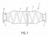
- the leakage detection member 8 may also be extended from the first end portion to the second end portion of the hose body 3 while wound in a spiral-like manner around the hose body 3, as illustrated in FIG. 7 . This is advantageous to more reliably and more quickly detect the occurrence of damage to the inner surface layer 4 across a wider range of the hose body 3.
- the leakage detection member 8 is embedded so as to extend inside the inner surface layer 4, making it possible to determine the occurrence of damage to the inner surface layer 4 by the leakage detector 10 before the inner surface layer 4 is completely penetrated and the fluid F leaks to the exterior of the inner surface layer 4.
- the occurrence of damage to the inner surface layer 4 can be detected more reliably and more quickly compared to the related art, making it possible to determine and avoid fatal damage of the marine hose 1 in advance.
- the specifications may also be configured so that the fluid penetration member 9 is disposed only in the range Z that is 100 mm frontward and rearward in the longitudinal direction of the hose body 3 with respect to the insertion side end E of the connection fitting 2.
- the inner surface layer 4 is susceptible to damage by stress concentration caused by external forces acting on the hose body 3.
- the fluid F that leaks upon damage to the first inner surface layer 4A can be effectively brought into contact with the leakage detection member 8 while minimizing the used amount of the fluid penetration member 9. Accordingly, the occurrence of damage to the inner surface layer 4 is more reliably and more quickly detected.
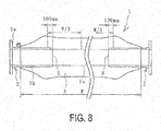
- the specifications may be configured so that, as illustrated in FIG. 8 , the fluid penetration member 9 is disposed in a range from a position of 100 mm on the rearward side in the longitudinal direction of the hose body 3 from the insertion side end E of the connection fitting 2 to a position at a length equivalent to at least 30% of a total length W of the hose body 3 on the frontward side.
- the fluid penetration member 9 is disposed in a range from a position of 100 mm on the rearward side in the longitudinal direction of the hose body 3 to a position at a length equivalent to 30% of the total length W of the hose body 3 on the frontward side. According to these specifications, the occurrence of damage to the inner surface layer 4 can be effectively determined while suppressing the used amount of the fluid penetration member 9.
- the fluid penetration member 9 may also be provided in a range Z1 from a position of 100 mm on the rearward side in the longitudinal direction of the hose body 3 with respect to the insertion side end E of the connection fitting 2 (nipple 2b) on the first end side to a position of 100 mm on the rearward side in the longitudinal direction of the hose body 3 with respect to the insertion side end E of the connection fitting 2 (nipple 2b) on the second end side.
- the fluid penetration member 9 may also be provided across the total length W (entire range) of the hose body 3.
Landscapes
- Engineering & Computer Science (AREA)
- General Engineering & Computer Science (AREA)
- Mechanical Engineering (AREA)
- Physics & Mathematics (AREA)
- General Physics & Mathematics (AREA)
- Rigid Pipes And Flexible Pipes (AREA)
- Pipeline Systems (AREA)
- Examining Or Testing Airtightness (AREA)
Abstract
Description
- The present invention relates to a marine hose status monitoring system, and particularly relates to a marine hose status monitoring system capable of more reliably and more quickly detecting the occurrence of damage to an inner surface layer of a hose body.
- A marine hose is used when connecting an offshore tanker to an onshore facility to convey crude oil, or the like. The environment under which the marine hose is used is various and involves different natural environments, including wave, wind, and tide environments. These natural environments constantly change. For example, when a typhoon or the like approaches and waves increase in height, large external forces act on the marine hose from various directions. As a result, the marine hose undergoes elongation, bending, twisting, and other various deformations. When the external forces that act on the marine hose become extremely large, increasing deformation, there is a danger that the marine hose will become damaged. Specifically, an inner surface layer constituting the hose body becomes damaged, causing the crude oil or the like conveyed through the marine hose to escape and diffuse into the surrounding area. Therefore, the capability of more reliably and more quickly detecting the occurrence of damage to the inner surface layer before the damage enlarges is desired.
- In the related art, various inventions for detecting the occurrence of damage to the inner surface layer of a marine hose have been proposed (refer to
Patent Document 1, for example). InPatent Document 1, a marine hose provided with an electrically conductive elastomer member embedded between an inner rubber layer constituting a hose body and a reinforcing layer disposed on an outer circumferential side thereof is proposed. According to the marine hose proposed in this literature, the electrically conductive elastomer member swells when the conveyed fluid leaks from the inner rubber layer. With the swelling of the electrically conductive elastomer member, a resistance value increases, making it possible to detect the leakage of the fluid from the inner rubber layer by detecting a change in this resistance value. Nevertheless, when minor damage before leakage of a fluid from the inner rubber layer occurs, the electrically conductive elastomer member does not swell. Further, when the amount of fluid that leaks is small, the swelling of the electrically conductive elastomer member conductive elastomer member is slight, making it impossible to determine the occurrence of damage to the inner surface rubber layer. Thus, there is room for improvement in more reliably and more quickly detecting the occurrence of damage to the inner rubber layer. - Patent Document 1:
JP 2009-2457 A - An object of the present invention is to provide a marine hose status monitoring system capable of more reliably and more quickly detecting the occurrence of damage to an inner surface layer of a hose body.
- A marine hose status monitoring system according to the present invention for achieving the above object is a monitoring system that determines a status of a marine hose including a hose body provided with an inner surface layer, a reinforcing layer disposed on an outer circumferential side of the inner surface layer, and an outer surface layer disposed on an outer circumferential side of the reinforcing layer; and a connection fitting connected to both end portions of the hose body in a longitudinal direction. The marine hose status monitoring system includes a leakage detection member embedded to extend inside the inner surface layer, and a leakage detector connected to the leakage detection member. The leakage detector determines that damage has occurred to the inner surface layer when a fluid flowing through a fluid flow path of the hose body comes into contact with the leakage detection member.
- According to the present invention, the leakage detection member is embedded so as to extend inside the inner surface layer constituting the hose body, making it possible to detect the occurrence of damage to the inner surface layer by the leakage detector when such damage occurs and conveyed fluid comes into contact with the leakage detection member. In this way, the occurrence of damage to the inner surface layer can be determined before the inner surface layer is penetrated and fluid leakage occurs. Thus, the occurrence of damage to the inner surface layer can be detected more reliably and more quickly compared to the related art.
- For example, the specifications are configured so that the marine hose status monitoring system further includes a fluid penetration member that is located adjacent to the leakage detection member, is embedded in the inner surface layer, and allows penetration of the fluid. This fluid penetration member is disposed in a range that is at least 100 mm frontward and rearward in the longitudinal direction of the hose body with respect to an insertion side end of the connection fitting. The range of at least 100 mm frontward and rearward in the longitudinal direction of the hose body with respect to the insertion side end of the connection fitting is a range where stress concentration occurs in the inner surface layer, and is thus readily susceptible to damage. Thus, when damage occurs to the inner surface layer, the fluid more readily penetrates the fluid penetration member, bringing the fluid into contact with the leakage detection member more reliably and more quickly. This is advantageous to more reliably and more quickly detecting the occurrence of damage to the inner surface layer. The fluid penetration member is, for example, located adjacent to the leakage detection member on an inner circumferential side of the hose body.
- To exhibit the advantages achieved by the fluid penetration member across a wider range, the specifications are configured so that, for example, the fluid penetration member is disposed in a range from a position of 100 mm on a rearward side in the longitudinal direction of the hose body from the insertion side end of the connection fitting to a position at a length equivalent to at least 30% of a total length of the hose body on a front side.
- The specifications may be configured so that the leakage detection member, for example, extends while winding in a spiral-like manner around the hose body. Or, the specifications may be configured so that the leakage detection member extends in the longitudinal direction of the hose body.
- Examples of the fluid penetration member used include a fiber layer having a cord fabric structure. Use of the fiber layer having a cord fabric structure allows the fluid to readily penetrate while suppressing an increase in a bending rigidity of the hose body.
- The specifications may also be configured so that the marine hose status monitoring system further includes a transmission unit that is connected to the leakage detector and receives input of detection data of the leakage detector, and a receiving unit that receives the detection data wirelessly transmitted from the transmission unit. According to these specifications, whether damage has occurred to the inner surface layer can be determined in real-time at a desired position away from the marine hose.
-
-
FIG. 1 is an explanatory diagram illustrating a marine hose status monitoring system of the present invention. -
FIG. 2 is an explanatory diagram illustrating a portion of the marine hose inFIG. 1 in a longitudinal sectional view. -
FIG. 3 is an explanatory diagram illustrating the marine hose inFIG. 1 in a front view (arrow view from one connection fitting side to the other connection fitting side). -
FIG. 4 is an explanatory diagram illustrating a fluid penetration member inFIG. 2 . -
FIG. 5 is an explanatory diagram illustrating a hose line formed so as to connect the marine hoses. -
FIG. 6 is an explanatory diagram illustrating a hose body that incurred damage to an inner surface layer, in a horizontal sectional view. -
FIG. 7 is an explanatory diagram illustrating another layout example of the leakage detection member. -
FIG. 8 is an explanatory diagram illustrating a range where the fluid penetration member is disposed. -
FIG. 9 is an explanatory diagram illustrating a modified example of the range where the fluid penetration member is disposed. - A marine hose status monitoring system according to the present invention will be described below on the basis of embodiments illustrated in the drawings.
- As illustrated in
FIGS. 1 to 3 , the marine hose status monitoring system (hereinafter referred to as "monitoring system 1") of the present invention includes amarine hose 1 having special specifications, and aleakage detector 10. Themarine hose 1 includes ahose body 3, and a connection fitting 2 connected to each of both end portions of thehose body 3 in a longitudinal direction. - The
hose body 3 includes an inner surface layer 4 (a firstinner surface layer 4A and a secondinner surface layer 4B), a reinforcing layer 5 (amain reinforcing layer 5A and abody wire layer 5B) disposed on an outer circumferential side of theinner surface layer 4, and anouter surface layer 7 disposed on an outer circumferential side of the reinforcinglayer 5. Thehose body 3 is further suitably provided with other required members. Themarine hose 1 of this embodiment is a floating type, and thus abuoyant layer 6 formed by a buoyant material such as sponge is interposed between the reinforcinglayer 5 and theouter surface layer 7. The present invention may be applied not only to themarine hose 1 of a floating type, but also to a marine hose of a sub-marine type that does not include thebuoyant layer 6. - The
connection fitting 2 includes aflange 2a that has a disc shape, and anipple 2b that has a tubular shape, is bonded to theflange 2a, and on a leading edge portion side is inserted into thehose body 3. The firstinner surface layer 4A, the secondinner surface layer 4B, the main reinforcinglayer 5A, and thebody wire layer 5B are wound and layered around an outer circumference of thenipple 2b, in that order toward the outer circumferential side, with an outermost circumference being covered by theouter surface layer 7. An inner circumferential side of the firstinner surface layer 4A serves as a fluid flow path 1a. A line segment CL inFIG. 2 is a center line that extends in an axial direction of themarine hose 1. - The
inner surface layer 4 that comes into contact with a fluid F conveyed through themarine hose 1 has a two-layer structure of the firstinner surface layer 4A and the secondinner surface layer 4B. The firstinner surface layer 4A that comes into direct contact with the conveyed fluid F and the second innercircumferential layer 4B adjacent to an outer circumferential side thereof are made from an acrylonitrile rubber or the like excellent in oil resistance, for example. Thebody wire layer 5B is configured by winding a metal wire around a rubber layer on an outer circumference of the main reinforcinglayer 5A in a spiral-like manner at a predetermined interval. The main reinforcinglayer 5A is configured by layering a plurality of reinforcing cord layers obtained by covering a reinforcing cord with rubber. -
Nipple wires layer 5A and thebody wire layer 5B are fixed to thenipple 2b by fixingrings 2c or the like projecting to an outer circumferential surface of thenipple 2b. Theouter surface layer 7 is made from a non-water-permeable material such as rubber. - Then, the
marine hose 1 further includes, as special specifications, aleakage detection member 8 that is embedded inside theinner surface layer 4 so as to extend between the firstinner surface layer 4A and the secondinner surface layer 4B. Theleakage detection member 8 extends in the longitudinal direction of thehose body 3, from a first end portion to a second end portion of thehose body 3 in the longitudinal direction. Examples of theleakage detection member 8 used include a swelling rubber that swells upon contact with the fluid F, such as crude oil, or a member that functions as a flow path that allows the fluid F to flow therethrough. - The
leakage detector 10 is, for example, attached to the outer circumferential side of thenipple 2b of the connection fitting 2, theflange 2a, or thehose body 3, and connected to theleakage detection member 8. Theleakage detector 10 is a device that determines that damage has occurred to the inner surface layer 4 (the firstinner surface layer 4A) when the fluid F flowing through the fluid flow path 1a comes into contact with theleakage detection member 8. - The
marine hose 1 of this embodiment further includes afluid penetration member 9 that is adjacent to theleakage detection member 8, is embedded in theinner surface layer 4, and allows penetration of the fluid F. Thisfluid penetration member 9 is disposed in a range Z that is at least 100 mm frontward and rearward in the longitudinal direction of thehose body 3 with respect to an insertion side end E of theconnection fitting 2. In this embodiment, thefluid penetration member 9 is disposed adjacent to an inner circumferential side of theleakage detection member 8. - The
fluid penetration member 9 is a member that allows penetration of the fluid F when in contact with the fluid F. Examples of thefluid penetration member 9 used include a fiber layer made from cotton, nylon, or the like. Specifically, a fiber layer having a cord fabric structure formed by a fiber such as cotton or nylon such as illustrated inFIG. 4 may be used. Use of the fiber layer having a cord fabric structure as thefluid penetration member 9 allows the fluid F to readily penetrate while suppressing an increase in a bending rigidity of thehose body 3. - According to this embodiment, the marine hose status monitoring system further includes a
transmission unit 11 that is connected to theleakage detector 10 and receives input of detection data (detection data indicating that damage has occurred to the inner surface layer 4) of theleakage detector 10, and a receivingunit 12 that receives the detection data wirelessly transmitted from thetransmission unit 11. Detection data is periodically input to thetransmission unit 11, and thistransmission unit 11 periodically wirelessly transmits the detection data to the receivingunit 12. For example, detection data is successively input to thetransmission unit 11, and thetransmission unit 11 successively wirelessly transmits this detection data to the receivingunit 12. The receivingunit 12 can be disposed in a desired position. - As illustrated in
FIG. 5 , a plurality of themarine hoses 1 are connected via therespective connection fittings 2, forming a hose line L. According to this embodiment, the hose line L is afloat on the ocean, and external forces act on themarine hoses 1 from waves, winds, and tides. As a result, themarine hose 1 undergoes elongation, bending, twisting, and other various deformations. - The method of using this monitoring system will be described below.
- When an external force acts on the
marine hose 1, excessively deforming thehose body 3 and causing damage to the firstinner surface layer 4A as illustrated inFIG. 6 , the fluid F conveyed through the fluid flow path 1a comes into contact with theleakage detection member 8. As a result, theleakage detector 10 determines through theleakage detection member 8 that damage has occurred to the inner surface layer 4 (the firstinner surface layer 4A). That is, the occurrence of damage to theinner surface layer 4 can be determined before theinner surface layer 4 is fully damaged and the fluid F penetrates theinner surface layer 4 and leaks to the exterior of theinner surface layer 4. For example, when a swelling rubber is used as theleakage detection member 8, the fluid F causes theleakage detection member 8 to swell and this fluid F is transmitted to theleakage detector 10. When a member that functions as a flow path that allows the fluid F to flow therethrough is used as theleakage detection member 8, the fluid F that leaks upon damage to the firstinner surface layer 4A flows through theleakage detection member 8 and is transmitted to theleakage detector 10. As a result, theleakage detector 10 can determine that damage has occurred to theinner surface layer 4. - Thus, disposing the
leakage detection member 8 across as wide a range as possible in the longitudinal direction of thehose body 3 is advantageous to more reliably determine the occurrence of damage to theinner surface layer 4. According to this embodiment, thefluid penetration member 9 penetrated by the fluid F allows the fluid F to readily come into contact (promotes contact) with theleakage detection member 8 adjacent thereto. As a result, even when there is minimal leakage of the fluid F when damage has occurred to the firstinner surface layer 4A, the fluid F penetrates thefluid penetration member 9, allowing the fluid F to come into contact with (promoting contact with) theleakage detection member 8 more reliably and more quickly. This is advantageous to more reliably and more quickly detect the occurrence of damage to theinner surface layer 4 by theleakage detector 10. Thus, similarly increasing a length across which thefluid penetration member 9 is adjacent to theleakage detection member 8 is advantageous to more reliably and more quickly detecting the occurrence of damage to theinner surface layer 4. - According to this embodiment, the
transmission unit 11 and the receivingunit 12 are further provided, making it possible to arrange the receivingunit 12 in a vessel or an onshore facility, for example. In this way, the status of themarine hose 1 can be determined in real-time at a desired position away from themarine hose 1. When the monitoring system is not provided with thetransmission unit 11 or the receivingunit 12, the status of themarine hose 1 is suitably determined by visually observing theleakage detector 10 or the like. - The
leakage detection member 8 may also be extended from the first end portion to the second end portion of thehose body 3 while wound in a spiral-like manner around thehose body 3, as illustrated inFIG. 7 . This is advantageous to more reliably and more quickly detect the occurrence of damage to theinner surface layer 4 across a wider range of thehose body 3. - As described above, according to the present invention, the
leakage detection member 8 is embedded so as to extend inside theinner surface layer 4, making it possible to determine the occurrence of damage to theinner surface layer 4 by theleakage detector 10 before theinner surface layer 4 is completely penetrated and the fluid F leaks to the exterior of theinner surface layer 4. Thus, the occurrence of damage to theinner surface layer 4 can be detected more reliably and more quickly compared to the related art, making it possible to determine and avoid fatal damage of themarine hose 1 in advance. - The specifications may also be configured so that the
fluid penetration member 9 is disposed only in the range Z that is 100 mm frontward and rearward in the longitudinal direction of thehose body 3 with respect to the insertion side end E of theconnection fitting 2. In this range Z, theinner surface layer 4 is susceptible to damage by stress concentration caused by external forces acting on thehose body 3. As a result, according to these specifications, the fluid F that leaks upon damage to the firstinner surface layer 4A can be effectively brought into contact with theleakage detection member 8 while minimizing the used amount of thefluid penetration member 9. Accordingly, the occurrence of damage to theinner surface layer 4 is more reliably and more quickly detected. - To exhibit the advantages achieved by the
fluid penetration member 9 across a wider range, the specifications may be configured so that, as illustrated inFIG. 8 , thefluid penetration member 9 is disposed in a range from a position of 100 mm on the rearward side in the longitudinal direction of thehose body 3 from the insertion side end E of the connection fitting 2 to a position at a length equivalent to at least 30% of a total length W of thehose body 3 on the frontward side. For example, thefluid penetration member 9 is disposed in a range from a position of 100 mm on the rearward side in the longitudinal direction of thehose body 3 to a position at a length equivalent to 30% of the total length W of thehose body 3 on the frontward side. According to these specifications, the occurrence of damage to theinner surface layer 4 can be effectively determined while suppressing the used amount of thefluid penetration member 9. - Alternatively, as illustrated in
FIG. 9 , thefluid penetration member 9 may also be provided in a range Z1 from a position of 100 mm on the rearward side in the longitudinal direction of thehose body 3 with respect to the insertion side end E of the connection fitting 2 (nipple 2b) on the first end side to a position of 100 mm on the rearward side in the longitudinal direction of thehose body 3 with respect to the insertion side end E of the connection fitting 2 (nipple 2b) on the second end side. Alternatively, thefluid penetration member 9 may also be provided across the total length W (entire range) of thehose body 3. -
- 1 Marine hose
- 1a Fluid flow path
- 2 Connection fitting
- 2a Flange
- 2b Nipple
- 2c Fixing ring
- 3 Hose body
- 4 Inner surface layer
- 4A First inner surface layer
- 4B Second inner surface layer
- 5 Reinforcing layer
- 5A Main reinforcing layer
- 5a Nipple wire
- 5B Body wire layer
- 5b Nipple wire
- 6 Buoyant layer
- 7 Outer surface layer
- 8 Leakage detection member
- 9 Fluid penetration member
- 10 Leakage detector
- 11 Transmission unit
- 12 Receiving unit
- F Fluid
- L Hose line
Claims (8)
- A marine hose status monitoring system that determines a status of a marine hose comprising a hose body provided with an inner surface layer, a reinforcing layer disposed on an outer circumferential side of the inner surface layer, and an outer surface layer disposed on an outer circumferential side of the reinforcing layer, and a connection fitting connected to both end portions of the hose body in a longitudinal direction, the marine hose status monitoring system comprising:a leakage detection member embedded to extend inside the inner surface layer; anda leakage detector connected to the leakage detection member;the leakage detector determining that damage has occurred to the inner surface layer when a fluid flowing through a fluid flow path of the hose body comes into contact with the leakage detection member.
- The marine hose status monitoring system according to claim 1, further comprising a fluid penetration member that is located adjacent to the leakage detection member, is embedded in the inner surface layer, and allows penetration of the fluid;
the fluid penetration member being disposed in a range that is at least 100 mm frontward and rearward in the longitudinal direction of the hose body with respect to an insertion side end of the connection fitting. - The marine hose status monitoring system according to claim 2, wherein the fluid penetration member is located adjacent to the leakage detection member on an inner circumferential side of the hose body.
- The marine hose status monitoring system according to claim 2 or 3, wherein the fluid penetration member is disposed in a range from a position of 100 mm on a rearward side in the longitudinal direction of the hose body from an insertion side end of the connection fitting to a position at a length equivalent to at least 30% of a total length of the hose body on a frontward side.
- The marine hose status monitoring system according to any one of claims 1 to 4, wherein the leakage detection member extends while winding in a spiral-like manner around the hose body.
- The marine hose status monitoring system according to any one of claims 1 to 4, wherein the leakage detection member extends in the longitudinal direction of the hose body.
- The marine hose status monitoring system according to any one of claims 1 to 6, wherein the fluid penetration member is a fiber layer having a cord fabric structure.
- The marine hose status monitoring system according to any one of claims 1 to 7, further comprising:a transmission unit that is connected to the leakage detector and receives input of detection data of the leakage detector; anda receiving unit that receives the detection data wirelessly transmitted from the transmission unit.
Applications Claiming Priority (2)
| Application Number | Priority Date | Filing Date | Title |
|---|---|---|---|
| JP2016019915A JP6623801B2 (en) | 2016-02-04 | 2016-02-04 | Marine hose condition monitoring system |
| PCT/JP2017/001662 WO2017135041A1 (en) | 2016-02-04 | 2017-01-19 | Marine hose status monitoring system |
Publications (3)
| Publication Number | Publication Date |
|---|---|
| EP3412952A1 true EP3412952A1 (en) | 2018-12-12 |
| EP3412952A4 EP3412952A4 (en) | 2019-10-16 |
| EP3412952B1 EP3412952B1 (en) | 2020-12-02 |
Family
ID=59499537
Family Applications (1)
| Application Number | Title | Priority Date | Filing Date |
|---|---|---|---|
| EP17747200.8A Active EP3412952B1 (en) | 2016-02-04 | 2017-01-19 | Marine hose status monitoring system |
Country Status (5)
| Country | Link |
|---|---|
| EP (1) | EP3412952B1 (en) |
| JP (1) | JP6623801B2 (en) |
| CN (1) | CN108700226B (en) |
| BR (1) | BR112018015861B1 (en) |
| WO (1) | WO2017135041A1 (en) |
Cited By (3)
| Publication number | Priority date | Publication date | Assignee | Title |
|---|---|---|---|---|
| CN113167414A (en) * | 2018-12-18 | 2021-07-23 | 横滨橡胶株式会社 | Fluid leakage sensing system for marine hose |
| CN113374946A (en) * | 2021-08-13 | 2021-09-10 | 中海油能源发展股份有限公司采油服务分公司 | Safety processing system for liquefied natural gas conveying hose |
| US11378207B2 (en) | 2019-11-22 | 2022-07-05 | Trinity Bay Equipment Holdings, LLC | Swaged pipe fitting systems and methods |
Families Citing this family (4)
| Publication number | Priority date | Publication date | Assignee | Title |
|---|---|---|---|---|
| JP7225949B2 (en) * | 2019-03-12 | 2023-02-21 | 横浜ゴム株式会社 | Marine hose fluid leak detector |
| JP7389327B2 (en) * | 2019-09-20 | 2023-11-30 | 横浜ゴム株式会社 | Marine hose fluid leak detection system |
| JP2024001435A (en) * | 2022-06-22 | 2024-01-10 | 横浜ゴム株式会社 | Marine hose monitoring system and method |
| CN116923651B (en) * | 2023-07-05 | 2024-03-05 | 广东工业大学 | A floating production and storage device |
Family Cites Families (13)
| Publication number | Priority date | Publication date | Assignee | Title |
|---|---|---|---|---|
| US4446892A (en) * | 1979-09-05 | 1984-05-08 | Maxwell Ag | Method and apparatus for monitoring lengths of hose |
| CN85107620A (en) * | 1985-10-16 | 1987-05-27 | 尼托斯堪的纳维亚公司 | Method for installing a testing device during the laying of a thermally insulated pipeline and such a testing device |
| IT1266168B1 (en) * | 1994-07-15 | 1996-12-23 | Manuli Rubber Ind Srl | DOUBLE CASE FLEXIBLE HOSE |
| JP3982908B2 (en) * | 1998-05-18 | 2007-09-26 | 横浜ゴム株式会社 | Damage detection device for marine hose damage detection |
| JP4076338B2 (en) * | 2001-11-16 | 2008-04-16 | 横浜ゴム株式会社 | Fluid transfer hose |
| JP2004239612A (en) * | 2003-02-03 | 2004-08-26 | Bridgestone Corp | Liquid leakage detection hose |
| US20040177891A1 (en) * | 2003-03-11 | 2004-09-16 | Spaolonzi Mauricio Pinto | Leak detection system and method for offshore hose lines |
| CN101095006A (en) * | 2004-12-28 | 2007-12-26 | 株式会社普利司通 | Management system for marine hose |
| US7453367B2 (en) * | 2005-12-12 | 2008-11-18 | Veyance Technologies, Inc. | Leak detection system and method for offshore hose lines |
| JP5013252B2 (en) * | 2007-06-22 | 2012-08-29 | 横浜ゴム株式会社 | Marine hose |
| JP2009002458A (en) * | 2007-06-22 | 2009-01-08 | Yokohama Rubber Co Ltd:The | Marine hose |
| JP5519204B2 (en) * | 2009-07-28 | 2014-06-11 | 横浜ゴム株式会社 | Marine hose |
| US9952170B2 (en) * | 2012-04-23 | 2018-04-24 | Eaton Intelligent Power Limited | Methods and systems for measuring hose resistance |
-
2016
- 2016-02-04 JP JP2016019915A patent/JP6623801B2/en active Active
-
2017
- 2017-01-19 WO PCT/JP2017/001662 patent/WO2017135041A1/en not_active Ceased
- 2017-01-19 BR BR112018015861-5A patent/BR112018015861B1/en active IP Right Grant
- 2017-01-19 CN CN201780009479.7A patent/CN108700226B/en active Active
- 2017-01-19 EP EP17747200.8A patent/EP3412952B1/en active Active
Cited By (4)
| Publication number | Priority date | Publication date | Assignee | Title |
|---|---|---|---|---|
| CN113167414A (en) * | 2018-12-18 | 2021-07-23 | 横滨橡胶株式会社 | Fluid leakage sensing system for marine hose |
| US11378207B2 (en) | 2019-11-22 | 2022-07-05 | Trinity Bay Equipment Holdings, LLC | Swaged pipe fitting systems and methods |
| CN113374946A (en) * | 2021-08-13 | 2021-09-10 | 中海油能源发展股份有限公司采油服务分公司 | Safety processing system for liquefied natural gas conveying hose |
| CN113374946B (en) * | 2021-08-13 | 2021-10-12 | 中海油能源发展股份有限公司采油服务分公司 | Safety processing system for liquefied natural gas conveying hose |
Also Published As
| Publication number | Publication date |
|---|---|
| EP3412952A4 (en) | 2019-10-16 |
| EP3412952B1 (en) | 2020-12-02 |
| CN108700226B (en) | 2020-03-27 |
| WO2017135041A1 (en) | 2017-08-10 |
| BR112018015861A2 (en) | 2018-12-26 |
| JP6623801B2 (en) | 2019-12-25 |
| JP2017137959A (en) | 2017-08-10 |
| CN108700226A (en) | 2018-10-23 |
| BR112018015861B1 (en) | 2022-10-04 |
Similar Documents
| Publication | Publication Date | Title |
|---|---|---|
| EP3412952B1 (en) | Marine hose status monitoring system | |
| EP3412951B1 (en) | Marine hose status monitoring system | |
| KR101604153B1 (en) | Hose with fault detection capability | |
| EP2864748B1 (en) | Assembly and seal test | |
| EP2662524B1 (en) | Flexible pipe body with buoyancy element and method of producing same | |
| US20150136264A1 (en) | Flexible pipe body and method | |
| EP4191109B1 (en) | Marine hose fluid leakage detection system | |
| JP7389313B2 (en) | Marine hose fluid leak detection system | |
| EP3412950A1 (en) | Marine hose | |
| EP4300065A1 (en) | Liquid-leakage detection device | |
| JP2024038850A (en) | Flaw detection cable with float | |
| US8910668B2 (en) | Hose for transporting fluids | |
| JP2001187986A (en) | Fluid transporting marine hose | |
| JP4285601B2 (en) | Hose line | |
| JPH0540389Y2 (en) | ||
| JP3354621B2 (en) | Transport leak detection hose | |
| JP2009068536A (en) | Marine hose | |
| JP2010002037A (en) | Life detecting device for high pressure hose |
Legal Events
| Date | Code | Title | Description |
|---|---|---|---|
| STAA | Information on the status of an ep patent application or granted ep patent |
Free format text: STATUS: THE INTERNATIONAL PUBLICATION HAS BEEN MADE |
|
| PUAI | Public reference made under article 153(3) epc to a published international application that has entered the european phase |
Free format text: ORIGINAL CODE: 0009012 |
|
| STAA | Information on the status of an ep patent application or granted ep patent |
Free format text: STATUS: REQUEST FOR EXAMINATION WAS MADE |
|
| 17P | Request for examination filed |
Effective date: 20180830 |
|
| AK | Designated contracting states |
Kind code of ref document: A1 Designated state(s): AL AT BE BG CH CY CZ DE DK EE ES FI FR GB GR HR HU IE IS IT LI LT LU LV MC MK MT NL NO PL PT RO RS SE SI SK SM TR |
|
| AX | Request for extension of the european patent |
Extension state: BA ME |
|
| DAV | Request for validation of the european patent (deleted) | ||
| DAX | Request for extension of the european patent (deleted) | ||
| A4 | Supplementary search report drawn up and despatched |
Effective date: 20190912 |
|
| RIC1 | Information provided on ipc code assigned before grant |
Ipc: F16L 33/01 20060101ALI20190906BHEP Ipc: F16L 11/12 20060101AFI20190906BHEP Ipc: F16L 33/30 20060101ALI20190906BHEP Ipc: F16L 11/133 20060101ALI20190906BHEP Ipc: F16L 11/02 20060101ALI20190906BHEP Ipc: F17D 5/02 20060101ALI20190906BHEP Ipc: G01M 3/28 20060101ALI20190906BHEP Ipc: F16L 11/08 20060101ALI20190906BHEP |
|
| GRAP | Despatch of communication of intention to grant a patent |
Free format text: ORIGINAL CODE: EPIDOSNIGR1 |
|
| STAA | Information on the status of an ep patent application or granted ep patent |
Free format text: STATUS: GRANT OF PATENT IS INTENDED |
|
| INTG | Intention to grant announced |
Effective date: 20200713 |
|
| GRAS | Grant fee paid |
Free format text: ORIGINAL CODE: EPIDOSNIGR3 |
|
| GRAA | (expected) grant |
Free format text: ORIGINAL CODE: 0009210 |
|
| STAA | Information on the status of an ep patent application or granted ep patent |
Free format text: STATUS: THE PATENT HAS BEEN GRANTED |
|
| AK | Designated contracting states |
Kind code of ref document: B1 Designated state(s): AL AT BE BG CH CY CZ DE DK EE ES FI FR GB GR HR HU IE IS IT LI LT LU LV MC MK MT NL NO PL PT RO RS SE SI SK SM TR |
|
| REG | Reference to a national code |
Ref country code: GB Ref legal event code: FG4D |
|
| REG | Reference to a national code |
Ref country code: AT Ref legal event code: REF Ref document number: 1341293 Country of ref document: AT Kind code of ref document: T Effective date: 20201215 Ref country code: CH Ref legal event code: EP |
|
| REG | Reference to a national code |
Ref country code: DE Ref legal event code: R096 Ref document number: 602017028801 Country of ref document: DE |
|
| REG | Reference to a national code |
Ref country code: IE Ref legal event code: FG4D |
|
| PG25 | Lapsed in a contracting state [announced via postgrant information from national office to epo] |
Ref country code: GR Free format text: LAPSE BECAUSE OF FAILURE TO SUBMIT A TRANSLATION OF THE DESCRIPTION OR TO PAY THE FEE WITHIN THE PRESCRIBED TIME-LIMIT Effective date: 20210303 Ref country code: FI Free format text: LAPSE BECAUSE OF FAILURE TO SUBMIT A TRANSLATION OF THE DESCRIPTION OR TO PAY THE FEE WITHIN THE PRESCRIBED TIME-LIMIT Effective date: 20201202 Ref country code: RS Free format text: LAPSE BECAUSE OF FAILURE TO SUBMIT A TRANSLATION OF THE DESCRIPTION OR TO PAY THE FEE WITHIN THE PRESCRIBED TIME-LIMIT Effective date: 20201202 Ref country code: NO Free format text: LAPSE BECAUSE OF FAILURE TO SUBMIT A TRANSLATION OF THE DESCRIPTION OR TO PAY THE FEE WITHIN THE PRESCRIBED TIME-LIMIT Effective date: 20210302 |
|
| REG | Reference to a national code |
Ref country code: NL Ref legal event code: MP Effective date: 20201202 |
|
| REG | Reference to a national code |
Ref country code: AT Ref legal event code: MK05 Ref document number: 1341293 Country of ref document: AT Kind code of ref document: T Effective date: 20201202 |
|
| PG25 | Lapsed in a contracting state [announced via postgrant information from national office to epo] |
Ref country code: BG Free format text: LAPSE BECAUSE OF FAILURE TO SUBMIT A TRANSLATION OF THE DESCRIPTION OR TO PAY THE FEE WITHIN THE PRESCRIBED TIME-LIMIT Effective date: 20210302 Ref country code: SE Free format text: LAPSE BECAUSE OF FAILURE TO SUBMIT A TRANSLATION OF THE DESCRIPTION OR TO PAY THE FEE WITHIN THE PRESCRIBED TIME-LIMIT Effective date: 20201202 Ref country code: PL Free format text: LAPSE BECAUSE OF FAILURE TO SUBMIT A TRANSLATION OF THE DESCRIPTION OR TO PAY THE FEE WITHIN THE PRESCRIBED TIME-LIMIT Effective date: 20201202 Ref country code: LV Free format text: LAPSE BECAUSE OF FAILURE TO SUBMIT A TRANSLATION OF THE DESCRIPTION OR TO PAY THE FEE WITHIN THE PRESCRIBED TIME-LIMIT Effective date: 20201202 |
|
| PG25 | Lapsed in a contracting state [announced via postgrant information from national office to epo] |
Ref country code: NL Free format text: LAPSE BECAUSE OF FAILURE TO SUBMIT A TRANSLATION OF THE DESCRIPTION OR TO PAY THE FEE WITHIN THE PRESCRIBED TIME-LIMIT Effective date: 20201202 Ref country code: HR Free format text: LAPSE BECAUSE OF FAILURE TO SUBMIT A TRANSLATION OF THE DESCRIPTION OR TO PAY THE FEE WITHIN THE PRESCRIBED TIME-LIMIT Effective date: 20201202 |
|
| REG | Reference to a national code |
Ref country code: LT Ref legal event code: MG9D |
|
| PG25 | Lapsed in a contracting state [announced via postgrant information from national office to epo] |
Ref country code: PT Free format text: LAPSE BECAUSE OF FAILURE TO SUBMIT A TRANSLATION OF THE DESCRIPTION OR TO PAY THE FEE WITHIN THE PRESCRIBED TIME-LIMIT Effective date: 20210405 Ref country code: RO Free format text: LAPSE BECAUSE OF FAILURE TO SUBMIT A TRANSLATION OF THE DESCRIPTION OR TO PAY THE FEE WITHIN THE PRESCRIBED TIME-LIMIT Effective date: 20201202 Ref country code: SK Free format text: LAPSE BECAUSE OF FAILURE TO SUBMIT A TRANSLATION OF THE DESCRIPTION OR TO PAY THE FEE WITHIN THE PRESCRIBED TIME-LIMIT Effective date: 20201202 Ref country code: SM Free format text: LAPSE BECAUSE OF FAILURE TO SUBMIT A TRANSLATION OF THE DESCRIPTION OR TO PAY THE FEE WITHIN THE PRESCRIBED TIME-LIMIT Effective date: 20201202 Ref country code: LT Free format text: LAPSE BECAUSE OF FAILURE TO SUBMIT A TRANSLATION OF THE DESCRIPTION OR TO PAY THE FEE WITHIN THE PRESCRIBED TIME-LIMIT Effective date: 20201202 Ref country code: EE Free format text: LAPSE BECAUSE OF FAILURE TO SUBMIT A TRANSLATION OF THE DESCRIPTION OR TO PAY THE FEE WITHIN THE PRESCRIBED TIME-LIMIT Effective date: 20201202 Ref country code: CZ Free format text: LAPSE BECAUSE OF FAILURE TO SUBMIT A TRANSLATION OF THE DESCRIPTION OR TO PAY THE FEE WITHIN THE PRESCRIBED TIME-LIMIT Effective date: 20201202 |
|
| REG | Reference to a national code |
Ref country code: DE Ref legal event code: R119 Ref document number: 602017028801 Country of ref document: DE |
|
| PG25 | Lapsed in a contracting state [announced via postgrant information from national office to epo] |
Ref country code: AT Free format text: LAPSE BECAUSE OF FAILURE TO SUBMIT A TRANSLATION OF THE DESCRIPTION OR TO PAY THE FEE WITHIN THE PRESCRIBED TIME-LIMIT Effective date: 20201202 |
|
| REG | Reference to a national code |
Ref country code: CH Ref legal event code: PL |
|
| PG25 | Lapsed in a contracting state [announced via postgrant information from national office to epo] |
Ref country code: MC Free format text: LAPSE BECAUSE OF FAILURE TO SUBMIT A TRANSLATION OF THE DESCRIPTION OR TO PAY THE FEE WITHIN THE PRESCRIBED TIME-LIMIT Effective date: 20201202 Ref country code: IS Free format text: LAPSE BECAUSE OF FAILURE TO SUBMIT A TRANSLATION OF THE DESCRIPTION OR TO PAY THE FEE WITHIN THE PRESCRIBED TIME-LIMIT Effective date: 20210402 Ref country code: LU Free format text: LAPSE BECAUSE OF NON-PAYMENT OF DUE FEES Effective date: 20210119 |
|
| REG | Reference to a national code |
Ref country code: BE Ref legal event code: MM Effective date: 20210131 |
|
| PLBE | No opposition filed within time limit |
Free format text: ORIGINAL CODE: 0009261 |
|
| STAA | Information on the status of an ep patent application or granted ep patent |
Free format text: STATUS: NO OPPOSITION FILED WITHIN TIME LIMIT |
|
| PG25 | Lapsed in a contracting state [announced via postgrant information from national office to epo] |
Ref country code: AL Free format text: LAPSE BECAUSE OF FAILURE TO SUBMIT A TRANSLATION OF THE DESCRIPTION OR TO PAY THE FEE WITHIN THE PRESCRIBED TIME-LIMIT Effective date: 20201202 |
|
| 26N | No opposition filed |
Effective date: 20210903 |
|
| PG25 | Lapsed in a contracting state [announced via postgrant information from national office to epo] |
Ref country code: SI Free format text: LAPSE BECAUSE OF FAILURE TO SUBMIT A TRANSLATION OF THE DESCRIPTION OR TO PAY THE FEE WITHIN THE PRESCRIBED TIME-LIMIT Effective date: 20201202 Ref country code: CH Free format text: LAPSE BECAUSE OF NON-PAYMENT OF DUE FEES Effective date: 20210131 Ref country code: DE Free format text: LAPSE BECAUSE OF NON-PAYMENT OF DUE FEES Effective date: 20210803 Ref country code: DK Free format text: LAPSE BECAUSE OF FAILURE TO SUBMIT A TRANSLATION OF THE DESCRIPTION OR TO PAY THE FEE WITHIN THE PRESCRIBED TIME-LIMIT Effective date: 20201202 Ref country code: LI Free format text: LAPSE BECAUSE OF NON-PAYMENT OF DUE FEES Effective date: 20210131 |
|
| PG25 | Lapsed in a contracting state [announced via postgrant information from national office to epo] |
Ref country code: ES Free format text: LAPSE BECAUSE OF FAILURE TO SUBMIT A TRANSLATION OF THE DESCRIPTION OR TO PAY THE FEE WITHIN THE PRESCRIBED TIME-LIMIT Effective date: 20201202 Ref country code: IE Free format text: LAPSE BECAUSE OF NON-PAYMENT OF DUE FEES Effective date: 20210119 |
|
| PG25 | Lapsed in a contracting state [announced via postgrant information from national office to epo] |
Ref country code: IS Free format text: LAPSE BECAUSE OF FAILURE TO SUBMIT A TRANSLATION OF THE DESCRIPTION OR TO PAY THE FEE WITHIN THE PRESCRIBED TIME-LIMIT Effective date: 20210402 |
|
| PG25 | Lapsed in a contracting state [announced via postgrant information from national office to epo] |
Ref country code: BE Free format text: LAPSE BECAUSE OF NON-PAYMENT OF DUE FEES Effective date: 20210131 |
|
| P01 | Opt-out of the competence of the unified patent court (upc) registered |
Effective date: 20230512 |
|
| PG25 | Lapsed in a contracting state [announced via postgrant information from national office to epo] |
Ref country code: CY Free format text: LAPSE BECAUSE OF FAILURE TO SUBMIT A TRANSLATION OF THE DESCRIPTION OR TO PAY THE FEE WITHIN THE PRESCRIBED TIME-LIMIT Effective date: 20201202 |
|
| PG25 | Lapsed in a contracting state [announced via postgrant information from national office to epo] |
Ref country code: HU Free format text: LAPSE BECAUSE OF FAILURE TO SUBMIT A TRANSLATION OF THE DESCRIPTION OR TO PAY THE FEE WITHIN THE PRESCRIBED TIME-LIMIT; INVALID AB INITIO Effective date: 20170119 |
|
| PG25 | Lapsed in a contracting state [announced via postgrant information from national office to epo] |
Ref country code: MK Free format text: LAPSE BECAUSE OF FAILURE TO SUBMIT A TRANSLATION OF THE DESCRIPTION OR TO PAY THE FEE WITHIN THE PRESCRIBED TIME-LIMIT Effective date: 20201202 |
|
| PG25 | Lapsed in a contracting state [announced via postgrant information from national office to epo] |
Ref country code: TR Free format text: LAPSE BECAUSE OF FAILURE TO SUBMIT A TRANSLATION OF THE DESCRIPTION OR TO PAY THE FEE WITHIN THE PRESCRIBED TIME-LIMIT Effective date: 20201202 |
|
| PG25 | Lapsed in a contracting state [announced via postgrant information from national office to epo] |
Ref country code: MT Free format text: LAPSE BECAUSE OF FAILURE TO SUBMIT A TRANSLATION OF THE DESCRIPTION OR TO PAY THE FEE WITHIN THE PRESCRIBED TIME-LIMIT Effective date: 20201202 |
|
| PGFP | Annual fee paid to national office [announced via postgrant information from national office to epo] |
Ref country code: GB Payment date: 20251127 Year of fee payment: 10 |
|
| PGFP | Annual fee paid to national office [announced via postgrant information from national office to epo] |
Ref country code: FR Payment date: 20251208 Year of fee payment: 10 |
|
| PGFP | Annual fee paid to national office [announced via postgrant information from national office to epo] |
Ref country code: IT Payment date: 20251219 Year of fee payment: 10 |