EP3412940A1 - Piston ring for an internal combustion engine - Google Patents
Piston ring for an internal combustion engine Download PDFInfo
- Publication number
- EP3412940A1 EP3412940A1 EP18179010.6A EP18179010A EP3412940A1 EP 3412940 A1 EP3412940 A1 EP 3412940A1 EP 18179010 A EP18179010 A EP 18179010A EP 3412940 A1 EP3412940 A1 EP 3412940A1
- Authority
- EP
- European Patent Office
- Prior art keywords
- piston
- ring
- ring body
- ridges
- set forth
- Prior art date
- Legal status (The legal status is an assumption and is not a legal conclusion. Google has not performed a legal analysis and makes no representation as to the accuracy of the status listed.)
- Granted
Links
Images


Classifications
-
- F—MECHANICAL ENGINEERING; LIGHTING; HEATING; WEAPONS; BLASTING
- F16—ENGINEERING ELEMENTS AND UNITS; GENERAL MEASURES FOR PRODUCING AND MAINTAINING EFFECTIVE FUNCTIONING OF MACHINES OR INSTALLATIONS; THERMAL INSULATION IN GENERAL
- F16J—PISTONS; CYLINDERS; SEALINGS
- F16J9/00—Piston-rings, e.g. non-metallic piston-rings, seats therefor; Ring sealings of similar construction
- F16J9/06—Piston-rings, e.g. non-metallic piston-rings, seats therefor; Ring sealings of similar construction using separate springs or elastic elements expanding the rings; Springs therefor ; Expansion by wedging
- F16J9/061—Piston-rings, e.g. non-metallic piston-rings, seats therefor; Ring sealings of similar construction using separate springs or elastic elements expanding the rings; Springs therefor ; Expansion by wedging using metallic coiled or blade springs
- F16J9/062—Coiled spring along the entire circumference
-
- F—MECHANICAL ENGINEERING; LIGHTING; HEATING; WEAPONS; BLASTING
- F02—COMBUSTION ENGINES; HOT-GAS OR COMBUSTION-PRODUCT ENGINE PLANTS
- F02F—CYLINDERS, PISTONS OR CASINGS, FOR COMBUSTION ENGINES; ARRANGEMENTS OF SEALINGS IN COMBUSTION ENGINES
- F02F1/00—Cylinders; Cylinder heads
- F02F1/18—Other cylinders
-
- F—MECHANICAL ENGINEERING; LIGHTING; HEATING; WEAPONS; BLASTING
- F16—ENGINEERING ELEMENTS AND UNITS; GENERAL MEASURES FOR PRODUCING AND MAINTAINING EFFECTIVE FUNCTIONING OF MACHINES OR INSTALLATIONS; THERMAL INSULATION IN GENERAL
- F16J—PISTONS; CYLINDERS; SEALINGS
- F16J9/00—Piston-rings, e.g. non-metallic piston-rings, seats therefor; Ring sealings of similar construction
- F16J9/06—Piston-rings, e.g. non-metallic piston-rings, seats therefor; Ring sealings of similar construction using separate springs or elastic elements expanding the rings; Springs therefor ; Expansion by wedging
-
- F—MECHANICAL ENGINEERING; LIGHTING; HEATING; WEAPONS; BLASTING
- F16—ENGINEERING ELEMENTS AND UNITS; GENERAL MEASURES FOR PRODUCING AND MAINTAINING EFFECTIVE FUNCTIONING OF MACHINES OR INSTALLATIONS; THERMAL INSULATION IN GENERAL
- F16J—PISTONS; CYLINDERS; SEALINGS
- F16J9/00—Piston-rings, e.g. non-metallic piston-rings, seats therefor; Ring sealings of similar construction
- F16J9/12—Details
- F16J9/20—Rings with special cross-section; Oil-scraping rings
- F16J9/206—One-piece oil-scraping rings
Definitions
- the present invention relates generally to internal combustion engines having at least one reciprocating piston within a cylinder, and more particularly to seals between the reciprocating piston and a cylinder wall.
- Typical internal combustion engines are provided with at least one piston body which reciprocates within a cylinder of an engine block.
- each piston body includes a plurality of ring grooves, each of which receives and operably supports a piston ring.
- the piston rings remain in the ring grooves and travel with their respective piston bodies in a reciprocating motion within cylinders of an engine block.
- the pistons rings function to seal combustion gasses in a combustion chamber above the piston body, to transfer heat from the piston body to the cylinder wall, to restrict the passage of oil from the crank case to the combustion chamber and to provide a generally uniform oil film on the cylinder wall.
- Such piston rings are typically biased with a spring force in a radially outward direction against the cylinder wall to establish the seal between the piston body and the cylinder wall.
- a piston ring for sealing a cylinder wall to a piston body.
- the piston ring includes a ring body which extends about an axis and has an inner face and an outer face.
- the inner face presents at least two ridges that extend in a radially inward direction with the ridges being spaced axially from one another by a valley region.
- the outer face of the ring body presents a groove, and a spring is seated in the groove.
- the spring substantially circumferentially surrounds the ring body and biases the ring body in the radially inward direction for sealing the ridges on the inner face against the piston body.
- the ring body also has at least one oil drainage port which extends radially between the valley region of the inner face and the groove on the outer surface for conveying oil out of the space between the ridges to the groove.
- the piston ring may be seated in a channel of a cylinder wall and sealed against the skirt of a piston body. As such, the piston ring remains generally stationary and does not move relative to the cylinder wall during operation of the engine. This location allows for increased stability of the piston body as it reciprocates in the cylinder of the engine without compromising the length of the skirt, i.e. the skirt may extend downwardly past the cylinder wall when the piston body is in a bottom dead center position.
- the piston ring also is resistant to blow by and has drainage ports for conveying oil out of the space between the ridges.
- the power cylinder assembly includes a cylinder wall that has a channel formed therein, and the channel extends circumferentially around the cylinder wall.
- the power cylinder assembly also includes a piston body having a skirt, and at least a portion of the skirt has an outer surface which extends continuously around a circumference.
- a piston ring is disposed in the channel of the cylinder wall, and the piston ring has a ring body which extends about an axis and has an inner face and an outer face.
- the inner face has at least two ridges which extend in a radially inward direction. The ridges are spaced from one another by a valley region, and the outer face of the ring body presents a groove.
- the piston ring further includes a spring which substantially circumferentially surrounds the ring body and is seated in the groove on the outer face.
- the spring biases the ring body in the radially inward direction to seal the ridges against the circumferentially continuous portion of the skirt of the piston body.
- the ring body also has at least one oil drainage port which extends radially between the valley region of the inner face and the groove of the outer face for conveying oil from between the ridges to the groove.
- FIG. 1 an exemplary embodiment of a piston ring 20 for sealing a piston body 22 to a cylinder wall 24 of a power cylinder assembly 26 of an internal combustion engine is generally shown in Figure 1 .
- the exemplary piston ring 20 is shown as installed in a power cylinder assembly 26 of an internal combustion engine having an engine block 28 and a two-piece cylinder liner 30 which together present an axially extending cylinder wall 24 having a channel 32 that extends substantially circumferentially around the cylinder wall 24.
- the piston ring 20 is disposed between ends of the cylinder liner 30 pieces which are spaced axially from one another to present the aforementioned channel 32.
- the channel 32 could be formed into the cylinder wall 24 through a range of different manners.
- the channel 32 could be formed directly into the engine block 28 without any cylinder liner 30.
- the exemplary piston ring 20 is shown installed in a diesel fueled compression ignition engine; however, it should be appreciated that the piston ring 20 could alternately be used in a range of different types of internal combustion engines including, for example, spark ignition engines or horizontally opposed two piston per cylinder engines.
- the piston body 22 of the exemplary power cylinder assembly 26 includes one or more upper piston rings 34 (a plurality being illustrated in the exemplary embodiment) which are carried in associated ring grooves formed in the outer wall of the piston body 22.
- the piston body 22 also has a skirt 36 which depends from the piston ring 20 region and helps guide the piston body 22 during reciprocation within the cylinder during operation of the engine. At least a portion of the skirt 36 is generally cylindrically-shaped and has an outer surface which extends continuously around a circumference. This portion of the skirt 36 is sized to be close to but relatively smaller than the inner diameter of the cylinder wall 24 such that there is an operating gap 38 therebetween.
- the piston body 22 is coupled by a wrist pin (not shown) or a similar type of connection device to a connecting rod 40, which in turn is coupled to a crank shaft (not shown) or a similar mechanism.
- the exemplary piston ring 20 in its location in the channel 32 of the cylinder wall 24, the exemplary piston ring 20 is mounted stationarily relative to the engine block 28 and is sealed against the outer surface of the skirt 36 of the piston body 22 to establish a gas and fluid tight seal between the cylinder wall 24 and the piston body 22.
- the piston ring 20 has an inner face 42 (best shown in Figure 4 ) that is in running contact with the skirt 36 of the piston body 22 during operation of the engine to seal combustion gasses in the combustion chamber on one side of the piston body 22 and to seal oil on the other side of the piston body 22, e.g. in a crank case (not shown) or any other oil chamber.
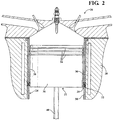
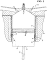
- the piston body 22 moves up and down within the cylinder wall 24 between a top dead center position shown in Figure 2 and a bottom dead center position shown in Figure 3 .
- the exemplary piston ring 20 remains in sealing engagement with the circumferentially continuous portion of the skirt 36 to maintain the gas and oil tight seal throughout the piston body's 22 range of travel.
- the location of the piston ring 20 in the channel 32 of the cylinder wall 24 allows for increased stability of the piston body 22 as it reciprocates in the cylinder of the engine without compromising the length of the skirt 36, i.e. the skirt 36 may extend downwardly into the crank case (not shown) when the piston body 22 is in the bottom dead center position.
- the exemplary piston ring 20 includes a ring body 44 that extends about an axis and has ends which are separated from one another by a ring gap 46.
- the ring body 44 has an inner face 42 with a pair of ridges 48 which are spaced axially from one another and extend in a radially inward direction. As shown, when installed in a power cylinder assembly 26, these ridges 48 directly and slidably engage the circumferentially continuous portion of the outer surface of the piston body 22 to establish the gas and oil tight seal between the cylinder wall 24 and the piston body 22. Between the ridges 48, the inner face 42 of the exemplary ring body 44 includes a generally flat valley region 50.
- the top and bottom surfaces of the ridges 48 are angled relative to the radial direction. These surfaces may be disposed at similar or different angles relative to the radial direction.
- the surfaces of the ridges 48 nearest the valley region 50 are disposed at approximately a ten degree angle relative to the radial direction, and the surfaces of the ridges 48 (opposite of the valley region 50 ) furthest from the valley region 50 are disposed at an angle of approximately twenty degrees relative to the radial direction.
- the portions of the inner face 42 above and below the ridges 48 are also disposed at an angle relative to the radial direction by approximately eighty degrees.
- intersections of the various surfaces of the inner face 42 are rounded or radiused. However, it should be appreciated that these intersections could alternately be sharp, i.e. non-rounded.
- the side of the ring body 44 opposite of the inner face 42 is an outer face 52 which presents a generally V-shaped groove 54.
- the piston ring 20 includes a coil spring 56 which is seated in the groove 54 and substantially circumferentially surrounds the ring body 44.
- the coil spring 56 exerts a biasing force against the ring body 44 to bias the ridges 48 of the inner face 42 against the outer surface of the piston body 22 and establish the aforementioned gas and oil tight seal between the cylinder wall 24 and the piston body 22.
- the ring body 44 of the exemplary piston ring 20 includes a plurality of oil drainage ports 58 which are spaced circumferentially from one another along the length of the ring body 44.
- the oil drainage ports 58 extend radially between the inner and outer faces 42, 52 of the ring body 44 for conveying oil out of the space between the ridges 48.
- the oil drainage ports 58 extend radially between the valley portion of the inner face 42 and the groove 54 of the outer face 52.
- the spaces between the coils of the coil spring 56 allow the oil to flow through the oil drainage ports 58 from the space between the ridges 48 to the other side of the ring body 44. The oil may then drain back to the crank case or the oil chamber below the piston body 22 during upward strokes of the piston body 22.
- the ring body 44 may be formed through any desirable manufacturing process and may be of any desirable material including, for example, cast iron or steel.
- the ring body 44 may also either be uncoated or may have a wear resistant coating (such as chromium, chromium with aluminum oxide ceramic [CKS], chromium with microdiamond [GDC], etc.) applied to at least its inner face 42.
- a wear resistant coating such as chromium, chromium with aluminum oxide ceramic [CKS], chromium with microdiamond [GDC], etc.
Abstract
Description
- This application claims the benefit of application serial number
61/600,329 filed February 17, 2012 - The present invention relates generally to internal combustion engines having at least one reciprocating piston within a cylinder, and more particularly to seals between the reciprocating piston and a cylinder wall.
- Typical internal combustion engines are provided with at least one piston body which reciprocates within a cylinder of an engine block. In general, each piston body includes a plurality of ring grooves, each of which receives and operably supports a piston ring. In operation, the piston rings remain in the ring grooves and travel with their respective piston bodies in a reciprocating motion within cylinders of an engine block. Among other things, the pistons rings function to seal combustion gasses in a combustion chamber above the piston body, to transfer heat from the piston body to the cylinder wall, to restrict the passage of oil from the crank case to the combustion chamber and to provide a generally uniform oil film on the cylinder wall. Such piston rings are typically biased with a spring force in a radially outward direction against the cylinder wall to establish the seal between the piston body and the cylinder wall.
- According to an aspect of the present invention, a piston ring for sealing a cylinder wall to a piston body is provided. The piston ring includes a ring body which extends about an axis and has an inner face and an outer face. The inner face presents at least two ridges that extend in a radially inward direction with the ridges being spaced axially from one another by a valley region. The outer face of the ring body presents a groove, and a spring is seated in the groove. The spring substantially circumferentially surrounds the ring body and biases the ring body in the radially inward direction for sealing the ridges on the inner face against the piston body. The ring body also has at least one oil drainage port which extends radially between the valley region of the inner face and the groove on the outer surface for conveying oil out of the space between the ridges to the groove.
- The piston ring may be seated in a channel of a cylinder wall and sealed against the skirt of a piston body. As such, the piston ring remains generally stationary and does not move relative to the cylinder wall during operation of the engine. This location allows for increased stability of the piston body as it reciprocates in the cylinder of the engine without compromising the length of the skirt, i.e. the skirt may extend downwardly past the cylinder wall when the piston body is in a bottom dead center position. The piston ring also is resistant to blow by and has drainage ports for conveying oil out of the space between the ridges.
- Another aspect of the present invention provides for a power cylinder assembly. The power cylinder assembly includes a cylinder wall that has a channel formed therein, and the channel extends circumferentially around the cylinder wall. The power cylinder assembly also includes a piston body having a skirt, and at least a portion of the skirt has an outer surface which extends continuously around a circumference. A piston ring is disposed in the channel of the cylinder wall, and the piston ring has a ring body which extends about an axis and has an inner face and an outer face. The inner face has at least two ridges which extend in a radially inward direction. The ridges are spaced from one another by a valley region, and the outer face of the ring body presents a groove. The piston ring further includes a spring which substantially circumferentially surrounds the ring body and is seated in the groove on the outer face. The spring biases the ring body in the radially inward direction to seal the ridges against the circumferentially continuous portion of the skirt of the piston body. The ring body also has at least one oil drainage port which extends radially between the valley region of the inner face and the groove of the outer face for conveying oil from between the ridges to the groove.
- These and other features and advantages of the present invention will be readily appreciated, as the same becomes better understood by reference to the following detailed description when considered in connection with the accompanying drawings wherein:
-
Figure 1 is a perspective and elevation view of an exemplary embodiment of a piston ring; -
Figure 2 is a sectional view of an exemplary embodiment of a power cylinder assembly and including the piston ring ofFigure 1 and showing a piston body in a top dead center position; -
Figure 3 is another sectional view of the exemplary embodiment of the power cylinder assembly with the piston ring ofFigure 1 and showing the piston body in a bottom dead center position; -
Figure 4 is a cross-sectional and fragmentary view showing the piston ring ofFigure 1 disposed within a channel of a cylinder wall and in sealing engagement with a piston body; -
Figure 5 is a cross-sectional and enlarged view showing a portion of the piston ring ofFigure 1 ; -
Figure 6 is a front elevation view of a ring body of the piston ring ofFigure 1 ; and -
Figure 7 is a top elevation view of the ring body of the piston ring ofFigure 1 . - Referring to the Figures, wherein like numerals indicate corresponding parts throughout the several views, an exemplary embodiment of a
piston ring 20 for sealing apiston body 22 to acylinder wall 24 of apower cylinder assembly 26 of an internal combustion engine is generally shown inFigure 1 . Referring now to the cross-sectional views ofFigures 2 and3 , theexemplary piston ring 20 is shown as installed in apower cylinder assembly 26 of an internal combustion engine having anengine block 28 and a two-piece cylinder liner 30 which together present an axially extendingcylinder wall 24 having achannel 32 that extends substantially circumferentially around thecylinder wall 24. Specifically, in the exemplary embodiment, thepiston ring 20 is disposed between ends of thecylinder liner 30 pieces which are spaced axially from one another to present theaforementioned channel 32. However, it should be appreciated that thechannel 32 could be formed into thecylinder wall 24 through a range of different manners. For example, thechannel 32 could be formed directly into theengine block 28 without anycylinder liner 30. Theexemplary piston ring 20 is shown installed in a diesel fueled compression ignition engine; however, it should be appreciated that thepiston ring 20 could alternately be used in a range of different types of internal combustion engines including, for example, spark ignition engines or horizontally opposed two piston per cylinder engines. - Referring still to
Figures 2 and3 , thepiston body 22 of the exemplarypower cylinder assembly 26 includes one or more upper piston rings 34 (a plurality being illustrated in the exemplary embodiment) which are carried in associated ring grooves formed in the outer wall of thepiston body 22. Thepiston body 22 also has askirt 36 which depends from thepiston ring 20 region and helps guide thepiston body 22 during reciprocation within the cylinder during operation of the engine. At least a portion of theskirt 36 is generally cylindrically-shaped and has an outer surface which extends continuously around a circumference. This portion of theskirt 36 is sized to be close to but relatively smaller than the inner diameter of thecylinder wall 24 such that there is anoperating gap 38 therebetween. Thepiston body 22 is coupled by a wrist pin (not shown) or a similar type of connection device to a connectingrod 40, which in turn is coupled to a crank shaft (not shown) or a similar mechanism. - Referring still to
Figures 2 and3 , in its location in thechannel 32 of thecylinder wall 24, theexemplary piston ring 20 is mounted stationarily relative to theengine block 28 and is sealed against the outer surface of theskirt 36 of thepiston body 22 to establish a gas and fluid tight seal between thecylinder wall 24 and thepiston body 22. Thepiston ring 20 has an inner face 42 (best shown inFigure 4 ) that is in running contact with theskirt 36 of thepiston body 22 during operation of the engine to seal combustion gasses in the combustion chamber on one side of thepiston body 22 and to seal oil on the other side of thepiston body 22, e.g. in a crank case (not shown) or any other oil chamber. During operation of the engine, thepiston body 22 moves up and down within thecylinder wall 24 between a top dead center position shown inFigure 2 and a bottom dead center position shown inFigure 3 . As shown, theexemplary piston ring 20 remains in sealing engagement with the circumferentially continuous portion of theskirt 36 to maintain the gas and oil tight seal throughout the piston body's 22 range of travel. The location of thepiston ring 20 in thechannel 32 of thecylinder wall 24 allows for increased stability of thepiston body 22 as it reciprocates in the cylinder of the engine without compromising the length of theskirt 36, i.e. theskirt 36 may extend downwardly into the crank case (not shown) when thepiston body 22 is in the bottom dead center position. - Referring back to
Figure 1 , theexemplary piston ring 20 includes aring body 44 that extends about an axis and has ends which are separated from one another by aring gap 46. Referring now toFigure 4 , thering body 44 has aninner face 42 with a pair ofridges 48 which are spaced axially from one another and extend in a radially inward direction. As shown, when installed in apower cylinder assembly 26, theseridges 48 directly and slidably engage the circumferentially continuous portion of the outer surface of thepiston body 22 to establish the gas and oil tight seal between thecylinder wall 24 and thepiston body 22. Between theridges 48, theinner face 42 of theexemplary ring body 44 includes a generallyflat valley region 50. In the exemplary embodiment, the top and bottom surfaces of theridges 48 are angled relative to the radial direction. These surfaces may be disposed at similar or different angles relative to the radial direction. For example, in the exemplary embodiment, the surfaces of theridges 48 nearest thevalley region 50 are disposed at approximately a ten degree angle relative to the radial direction, and the surfaces of the ridges 48 (opposite of the valley region 50) furthest from thevalley region 50 are disposed at an angle of approximately twenty degrees relative to the radial direction. In the exemplary embodiment, the portions of theinner face 42 above and below theridges 48 are also disposed at an angle relative to the radial direction by approximately eighty degrees. It should be appreciated that these surfaces could be disposed at any suitable angles relative to the radial or axial direction and could have any suitable dimensions. Additionally, in the exemplary embodiment, the intersections of the various surfaces of theinner face 42 are rounded or radiused. However, it should be appreciated that these intersections could alternately be sharp, i.e. non-rounded. - Referring still to
Figure 4 , the side of thering body 44 opposite of theinner face 42 is anouter face 52 which presents a generally V-shapedgroove 54. Thepiston ring 20 includes acoil spring 56 which is seated in thegroove 54 and substantially circumferentially surrounds thering body 44. Thecoil spring 56 exerts a biasing force against thering body 44 to bias theridges 48 of theinner face 42 against the outer surface of thepiston body 22 and establish the aforementioned gas and oil tight seal between thecylinder wall 24 and thepiston body 22. - Referring now to
Figure 6 , thering body 44 of theexemplary piston ring 20 includes a plurality ofoil drainage ports 58 which are spaced circumferentially from one another along the length of thering body 44. As shown inFigure 4 , theoil drainage ports 58 extend radially between the inner andouter faces ring body 44 for conveying oil out of the space between theridges 48. Specifically, theoil drainage ports 58 extend radially between the valley portion of theinner face 42 and thegroove 54 of theouter face 52. The spaces between the coils of thecoil spring 56 allow the oil to flow through theoil drainage ports 58 from the space between theridges 48 to the other side of thering body 44. The oil may then drain back to the crank case or the oil chamber below thepiston body 22 during upward strokes of thepiston body 22. - The
ring body 44 may be formed through any desirable manufacturing process and may be of any desirable material including, for example, cast iron or steel. Thering body 44 may also either be uncoated or may have a wear resistant coating (such as chromium, chromium with aluminum oxide ceramic [CKS], chromium with microdiamond [GDC], etc.) applied to at least itsinner face 42. - The exemplary description of the embodiment is meant to be illustrative and not limiting of the invention. Variations and modifications to the disclosed embodiment may become apparent to those skilled in the art and come within the scope of the invention.
Claims (14)
- A piston ring for sealing a cylinder wall to a piston body, comprising:a ring body which extends about an axis and has an inner face and an outer face, said inner face presenting at least two ridges that extend in a radially inward direction, said ridges being spaced from one another by a valley portion, and said outer face presenting a groove;a spring substantially circumferentially surrounding said ring body and seated in said groove on said outer face and biasing said ring body in said radially inward direction for sealing said ridges against the piston body; andsaid ring body having at least one oil drainage port extending radially between said valley region of said inner face and said groove on said outer face for conveying oil from between said ridges to said groove.
- The piston ring as set forth in claim 1 wherein said spring is a coil spring.
- The piston ring as set forth in claim 1 wherein said at least one oil drainage port in said ring body is further defined as a plurality of oil drainage ports spaced circumferentially from one another.
- The piston ring as set forth in claim 1 wherein said at least two inwardly extending ridges on said inner face of said ring body is further defined as a pair of inwardly extending ridges.
- The piston ring as set forth in claim 1 wherein said ring body has a gap.
- The piston ring as set forth in claim 1 wherein said ring body is uncoated.
- The piston ring as set forth in claim 1 wherein said ring body is of cast iron or steel.
- A power cylinder assembly, comprising:a cylinder wall having a channel formed therein, said channel extending substantially circumferentially around said cylinder wall;a piston body having a skirt and wherein at least a portion of an outer surface of said skirt extends continuously around a circumference;a piston ring disposed in said channel of said cylinder wall;said piston ring having a ring body that extends about an axis and has an inner face and an outer face, said inner face having at least two ridges that extend in a radially inward direction, said ridges being spaced from one another by a valley region, and said outer face presenting a groove;said piston ring further including a spring substantially circumferentially surrounding said ring body and seated in said groove on said outer face, said spring biasing said ring body in said radially inward direction to seal said ridges against said circumferentially continuous portion of said skirt of said piston body; andsaid ring body having at least one oil drainage port extending radially between said valley region of said inner face and said groove of said outer face for conveying oil from between said ridges to said groove.
- The power cylinder assembly as set forth in claim 1 wherein said spring is a coil spring.
- The power cylinder assembly as set forth in claim 1 wherein said at least one oil drainage port in said ring body is further defined as a plurality of oil drainage ports spaced circumferentially from one another.
- The power cylinder assembly as set forth in claim 1 wherein said at least two inwardly extending ridges on said inner face of said ring body is further defined as a pair of inwardly extending ridges.
- The power cylinder assembly as set forth in claim 1 wherein said ring body has a gap.
- The power cylinder assembly as set forth in claim 1 wherein said ring body is uncoated.
- The power cylinder assembly as set forth in claim 1 wherein said ring body is of cast iron or steel.
Applications Claiming Priority (3)
| Application Number | Priority Date | Filing Date | Title |
|---|---|---|---|
| US201261600329P | 2012-02-17 | 2012-02-17 | |
| PCT/US2013/026275 WO2013123284A1 (en) | 2012-02-17 | 2013-02-15 | Piston ring for an internal combustion engine |
| EP13707749.1A EP2815155B1 (en) | 2012-02-17 | 2013-02-15 | Piston ring for an internal combustion engine |
Related Parent Applications (2)
| Application Number | Title | Priority Date | Filing Date |
|---|---|---|---|
| EP13707749.1A Division EP2815155B1 (en) | 2012-02-17 | 2013-02-15 | Piston ring for an internal combustion engine |
| EP13707749.1A Division-Into EP2815155B1 (en) | 2012-02-17 | 2013-02-15 | Piston ring for an internal combustion engine |
Publications (2)
| Publication Number | Publication Date |
|---|---|
| EP3412940A1 true EP3412940A1 (en) | 2018-12-12 |
| EP3412940B1 EP3412940B1 (en) | 2020-07-15 |
Family
ID=47827437
Family Applications (2)
| Application Number | Title | Priority Date | Filing Date |
|---|---|---|---|
| EP18179010.6A Active EP3412940B1 (en) | 2012-02-17 | 2013-02-15 | Piston ring for an internal combustion engine |
| EP13707749.1A Not-in-force EP2815155B1 (en) | 2012-02-17 | 2013-02-15 | Piston ring for an internal combustion engine |
Family Applications After (1)
| Application Number | Title | Priority Date | Filing Date |
|---|---|---|---|
| EP13707749.1A Not-in-force EP2815155B1 (en) | 2012-02-17 | 2013-02-15 | Piston ring for an internal combustion engine |
Country Status (7)
| Country | Link |
|---|---|
| US (1) | US10125869B2 (en) |
| EP (2) | EP3412940B1 (en) |
| JP (1) | JP6230547B2 (en) |
| KR (1) | KR101968490B1 (en) |
| CN (1) | CN104220791B (en) |
| BR (1) | BR112014020382B1 (en) |
| WO (1) | WO2013123284A1 (en) |
Families Citing this family (5)
| Publication number | Priority date | Publication date | Assignee | Title |
|---|---|---|---|---|
| CN103527343A (en) * | 2013-09-22 | 2014-01-22 | 安徽中鼎动力有限公司 | Arranging method of piston oil rings of engine |
| JP2017056166A (en) | 2015-09-14 | 2017-03-23 | エンゼルプレイングカード株式会社 | Abnormality detection system in game parlor |
| CN107035565A (en) * | 2017-06-07 | 2017-08-11 | 韩侠 | A kind of piston ring with long service life |
| EP3724479A4 (en) * | 2017-12-14 | 2021-08-25 | Cummins Inc. | Antipolishing ring |
| CN109057986B (en) * | 2018-07-24 | 2020-10-09 | 安庆瑞莱博汽车配件有限公司 | Wear-resistant durable automobile engine piston ring |
Citations (4)
| Publication number | Priority date | Publication date | Assignee | Title |
|---|---|---|---|---|
| GB345313A (en) * | 1929-09-23 | 1931-03-23 | Ig Farbenindustrie Ag | An improved packing device for internal combustion engines run on pulverulent fuel |
| FR2030083A1 (en) * | 1968-12-04 | 1970-10-30 | Cornelius Henning | |
| WO2003044400A1 (en) * | 2001-11-22 | 2003-05-30 | Mt Sealing Technology Inc. | Oil scraper ring divided into segments |
| WO2011072063A1 (en) * | 2009-12-09 | 2011-06-16 | Ecomotors International, Inc. | Seal assembly for an internal combustion engine |
Family Cites Families (36)
| Publication number | Priority date | Publication date | Assignee | Title |
|---|---|---|---|---|
| US580090A (en) | 1897-04-06 | Gas or gasolene engine | ||
| US1682130A (en) | 1928-08-28 | Packing ring | ||
| US945233A (en) | 1909-05-12 | 1910-01-04 | Anderston Foundry Company Ltd | Internal-combustion engine. |
| US1015502A (en) | 1910-09-30 | 1912-01-23 | John W Meaker | Explosive-engine. |
| US1218132A (en) | 1916-09-25 | 1917-03-06 | Daniel Tuhey | Internal-combustion engine. |
| US1436130A (en) | 1920-01-27 | 1922-11-21 | Webb Cecil | Two-stroke-cycle internal-combustion engine |
| US1959769A (en) | 1930-08-23 | 1934-05-22 | Sulzer Ag | Internal combustion engine |
| US1871820A (en) | 1930-09-13 | 1932-08-16 | American Hammered Piston Ring | Packing |
| US2514016A (en) | 1945-02-16 | 1950-07-04 | Casado Daniel Valbuena | Cylinder and piston arrangement for internal-combustion engines |
| US2426613A (en) | 1945-08-30 | 1947-09-02 | Maunsell B Jackson | Packing means for pistons |
| US2614899A (en) * | 1951-05-07 | 1952-10-21 | Hastings Mfg Co | Piston ring |
| CH472573A (en) | 1967-03-22 | 1969-05-15 | Eisenegger Edwin | Device for the lubrication of piston machines |
| DE1945924A1 (en) | 1969-09-11 | 1971-03-18 | Lenger Karl Werner | Free piston machine |
| US4247972A (en) * | 1979-01-26 | 1981-02-03 | Sealed Power Corporation | Method of manufacturing a piston ring |
| JPS6138266A (en) * | 1984-07-31 | 1986-02-24 | Mitsubishi Heavy Ind Ltd | Piston rod gland packing equipping with gas-tight ring |
| FR2590641B1 (en) * | 1985-11-25 | 1989-07-13 | Snecma | COMPOSITE SEALING DEVICE |
| DE3743726C1 (en) * | 1987-12-23 | 1989-04-27 | Busak & Luyken Gmbh & Co | Sealing arrangement |
| JP2823602B2 (en) * | 1989-09-27 | 1998-11-11 | 臼井国際産業株式会社 | piston ring |
| KR100450441B1 (en) * | 2001-10-30 | 2004-09-30 | 삼영기계주식회사 | Piston Assembly having Contraflow Thwarting Construction in Internal Combustion Engine |
| CN1374445A (en) * | 2002-04-18 | 2002-10-16 | 王彦海 | Completely closed piston and piston ring assembly |
| EP1837561B1 (en) * | 2002-10-29 | 2009-11-11 | Toyota Jidosha Kabushiki Kaisha | Oil ring |
| JP2006125530A (en) * | 2004-10-29 | 2006-05-18 | Kanai Hiroaki | Piston ring and method of manufacturing the same |
| US7735834B2 (en) | 2005-12-07 | 2010-06-15 | Fev Engine Technology, Inc. | Two-stroke internal combustion engine with oil ring |
| JP2007170455A (en) * | 2005-12-20 | 2007-07-05 | Teikoku Piston Ring Co Ltd | Combined oil ring |
| JP2007255474A (en) * | 2006-03-21 | 2007-10-04 | Toyota Motor Corp | Piston ring |
| CN200961532Y (en) * | 2006-10-16 | 2007-10-17 | 浙江普礼汽配制造有限公司 | Diamond like carbon film steel oil ring |
| CN201103490Y (en) * | 2007-11-08 | 2008-08-20 | 石家庄金刚内燃机零部件集团有限公司 | Energy-saving piston ring of 6160 type diesel engine |
| BRPI0901045A2 (en) * | 2009-04-30 | 2010-12-28 | Mahle Metal Leve Sa | oil control ring (1) consisting of a ferrous body less than 2.0 mm high for internal combustion engines |
| US20100319661A1 (en) * | 2009-06-01 | 2010-12-23 | Achates Power, Inc. | Cylinder-Mounted oil wiper for an opposed piston engine |
| WO2010151695A2 (en) | 2009-06-24 | 2010-12-29 | Solar Storage Company | Cylinder rings |
| JP5773500B2 (en) * | 2010-04-19 | 2015-09-02 | 日本ピストンリング株式会社 | Oil ring for internal combustion engine |
| CN101929405B (en) * | 2010-08-12 | 2013-05-08 | 江铃汽车股份有限公司 | Piston ring of chrome-base ceramic composite plating layer |
| CN201875119U (en) * | 2010-10-27 | 2011-06-22 | 南京飞燕活塞环股份有限公司 | High-power piston ring assembly for rail transit brake system |
| CN202228205U (en) * | 2011-09-05 | 2012-05-23 | 中外合资安庆帝伯格茨活塞环有限公司 | Piston oil ring with drilled holes |
| CN102352800A (en) * | 2011-10-26 | 2012-02-15 | 李怀志 | Piston ring with long service life |
| CN102900560A (en) * | 2012-07-05 | 2013-01-30 | 浙江普礼汽配制造有限公司 | Diamond-like carbon membrane piston ring |
-
2013
- 2013-02-15 EP EP18179010.6A patent/EP3412940B1/en active Active
- 2013-02-15 KR KR1020147025337A patent/KR101968490B1/en active IP Right Grant
- 2013-02-15 US US13/768,196 patent/US10125869B2/en active Active
- 2013-02-15 BR BR112014020382-2A patent/BR112014020382B1/en not_active IP Right Cessation
- 2013-02-15 JP JP2014557797A patent/JP6230547B2/en not_active Expired - Fee Related
- 2013-02-15 WO PCT/US2013/026275 patent/WO2013123284A1/en active Application Filing
- 2013-02-15 EP EP13707749.1A patent/EP2815155B1/en not_active Not-in-force
- 2013-02-15 CN CN201380019889.1A patent/CN104220791B/en not_active Expired - Fee Related
Patent Citations (4)
| Publication number | Priority date | Publication date | Assignee | Title |
|---|---|---|---|---|
| GB345313A (en) * | 1929-09-23 | 1931-03-23 | Ig Farbenindustrie Ag | An improved packing device for internal combustion engines run on pulverulent fuel |
| FR2030083A1 (en) * | 1968-12-04 | 1970-10-30 | Cornelius Henning | |
| WO2003044400A1 (en) * | 2001-11-22 | 2003-05-30 | Mt Sealing Technology Inc. | Oil scraper ring divided into segments |
| WO2011072063A1 (en) * | 2009-12-09 | 2011-06-16 | Ecomotors International, Inc. | Seal assembly for an internal combustion engine |
Also Published As
| Publication number | Publication date |
|---|---|
| EP2815155A1 (en) | 2014-12-24 |
| CN104220791B (en) | 2017-06-23 |
| WO2013123284A1 (en) | 2013-08-22 |
| KR20140125849A (en) | 2014-10-29 |
| BR112014020382B1 (en) | 2020-09-24 |
| JP2015508874A (en) | 2015-03-23 |
| CN104220791A (en) | 2014-12-17 |
| EP3412940B1 (en) | 2020-07-15 |
| US10125869B2 (en) | 2018-11-13 |
| US20130213219A1 (en) | 2013-08-22 |
| JP6230547B2 (en) | 2017-11-15 |
| EP2815155B1 (en) | 2018-08-08 |
| KR101968490B1 (en) | 2019-04-12 |
Similar Documents
| Publication | Publication Date | Title |
|---|---|---|
| JP6490775B2 (en) | Piston rings for internal combustion engines | |
| EP2815155B1 (en) | Piston ring for an internal combustion engine | |
| EP2815156B1 (en) | Piston ring for an internal combustion engine | |
| US20140000549A1 (en) | Compression ring for an engine | |
| EP2815116B1 (en) | Piston ring for an internal combustion engine | |
| US20130213221A1 (en) | Piston ring for an internal combustion engine |
Legal Events
| Date | Code | Title | Description |
|---|---|---|---|
| PUAI | Public reference made under article 153(3) epc to a published international application that has entered the european phase |
Free format text: ORIGINAL CODE: 0009012 |
|
| STAA | Information on the status of an ep patent application or granted ep patent |
Free format text: STATUS: THE APPLICATION HAS BEEN PUBLISHED |
|
| AC | Divisional application: reference to earlier application |
Ref document number: 2815155 Country of ref document: EP Kind code of ref document: P |
|
| AK | Designated contracting states |
Kind code of ref document: A1 Designated state(s): AL AT BE BG CH CY CZ DE DK EE ES FI FR GB GR HR HU IE IS IT LI LT LU LV MC MK MT NL NO PL PT RO RS SE SI SK SM TR |
|
| STAA | Information on the status of an ep patent application or granted ep patent |
Free format text: STATUS: REQUEST FOR EXAMINATION WAS MADE |
|
| 17P | Request for examination filed |
Effective date: 20190321 |
|
| RBV | Designated contracting states (corrected) |
Designated state(s): AL AT BE BG CH CY CZ DE DK EE ES FI FR GB GR HR HU IE IS IT LI LT LU LV MC MK MT NL NO PL PT RO RS SE SI SK SM TR |
|
| GRAP | Despatch of communication of intention to grant a patent |
Free format text: ORIGINAL CODE: EPIDOSNIGR1 |
|
| STAA | Information on the status of an ep patent application or granted ep patent |
Free format text: STATUS: GRANT OF PATENT IS INTENDED |
|
| INTG | Intention to grant announced |
Effective date: 20200203 |
|
| RAP1 | Party data changed (applicant data changed or rights of an application transferred) |
Owner name: TENNECO INC. |
|
| GRAS | Grant fee paid |
Free format text: ORIGINAL CODE: EPIDOSNIGR3 |
|
| GRAA | (expected) grant |
Free format text: ORIGINAL CODE: 0009210 |
|
| STAA | Information on the status of an ep patent application or granted ep patent |
Free format text: STATUS: THE PATENT HAS BEEN GRANTED |
|
| AC | Divisional application: reference to earlier application |
Ref document number: 2815155 Country of ref document: EP Kind code of ref document: P |
|
| AK | Designated contracting states |
Kind code of ref document: B1 Designated state(s): AL AT BE BG CH CY CZ DE DK EE ES FI FR GB GR HR HU IE IS IT LI LT LU LV MC MK MT NL NO PL PT RO RS SE SI SK SM TR |
|
| REG | Reference to a national code |
Ref country code: GB Ref legal event code: FG4D Ref country code: CH Ref legal event code: EP |
|
| REG | Reference to a national code |
Ref country code: IE Ref legal event code: FG4D |
|
| REG | Reference to a national code |
Ref country code: DE Ref legal event code: R096 Ref document number: 602013070834 Country of ref document: DE |
|
| REG | Reference to a national code |
Ref country code: AT Ref legal event code: REF Ref document number: 1291396 Country of ref document: AT Kind code of ref document: T Effective date: 20200815 |
|
| REG | Reference to a national code |
Ref country code: SE Ref legal event code: TRGR |
|
| REG | Reference to a national code |
Ref country code: LT Ref legal event code: MG4D |
|
| REG | Reference to a national code |
Ref country code: AT Ref legal event code: MK05 Ref document number: 1291396 Country of ref document: AT Kind code of ref document: T Effective date: 20200715 |
|
| REG | Reference to a national code |
Ref country code: NL Ref legal event code: MP Effective date: 20200715 |
|
| PG25 | Lapsed in a contracting state [announced via postgrant information from national office to epo] |
Ref country code: GR Free format text: LAPSE BECAUSE OF FAILURE TO SUBMIT A TRANSLATION OF THE DESCRIPTION OR TO PAY THE FEE WITHIN THE PRESCRIBED TIME-LIMIT Effective date: 20201016 Ref country code: AT Free format text: LAPSE BECAUSE OF FAILURE TO SUBMIT A TRANSLATION OF THE DESCRIPTION OR TO PAY THE FEE WITHIN THE PRESCRIBED TIME-LIMIT Effective date: 20200715 Ref country code: FI Free format text: LAPSE BECAUSE OF FAILURE TO SUBMIT A TRANSLATION OF THE DESCRIPTION OR TO PAY THE FEE WITHIN THE PRESCRIBED TIME-LIMIT Effective date: 20200715 Ref country code: LT Free format text: LAPSE BECAUSE OF FAILURE TO SUBMIT A TRANSLATION OF THE DESCRIPTION OR TO PAY THE FEE WITHIN THE PRESCRIBED TIME-LIMIT Effective date: 20200715 Ref country code: HR Free format text: LAPSE BECAUSE OF FAILURE TO SUBMIT A TRANSLATION OF THE DESCRIPTION OR TO PAY THE FEE WITHIN THE PRESCRIBED TIME-LIMIT Effective date: 20200715 Ref country code: PT Free format text: LAPSE BECAUSE OF FAILURE TO SUBMIT A TRANSLATION OF THE DESCRIPTION OR TO PAY THE FEE WITHIN THE PRESCRIBED TIME-LIMIT Effective date: 20201116 Ref country code: BG Free format text: LAPSE BECAUSE OF FAILURE TO SUBMIT A TRANSLATION OF THE DESCRIPTION OR TO PAY THE FEE WITHIN THE PRESCRIBED TIME-LIMIT Effective date: 20201015 Ref country code: NO Free format text: LAPSE BECAUSE OF FAILURE TO SUBMIT A TRANSLATION OF THE DESCRIPTION OR TO PAY THE FEE WITHIN THE PRESCRIBED TIME-LIMIT Effective date: 20201015 Ref country code: ES Free format text: LAPSE BECAUSE OF FAILURE TO SUBMIT A TRANSLATION OF THE DESCRIPTION OR TO PAY THE FEE WITHIN THE PRESCRIBED TIME-LIMIT Effective date: 20200715 |
|
| PG25 | Lapsed in a contracting state [announced via postgrant information from national office to epo] |
Ref country code: IS Free format text: LAPSE BECAUSE OF FAILURE TO SUBMIT A TRANSLATION OF THE DESCRIPTION OR TO PAY THE FEE WITHIN THE PRESCRIBED TIME-LIMIT Effective date: 20201115 Ref country code: PL Free format text: LAPSE BECAUSE OF FAILURE TO SUBMIT A TRANSLATION OF THE DESCRIPTION OR TO PAY THE FEE WITHIN THE PRESCRIBED TIME-LIMIT Effective date: 20200715 Ref country code: LV Free format text: LAPSE BECAUSE OF FAILURE TO SUBMIT A TRANSLATION OF THE DESCRIPTION OR TO PAY THE FEE WITHIN THE PRESCRIBED TIME-LIMIT Effective date: 20200715 Ref country code: RS Free format text: LAPSE BECAUSE OF FAILURE TO SUBMIT A TRANSLATION OF THE DESCRIPTION OR TO PAY THE FEE WITHIN THE PRESCRIBED TIME-LIMIT Effective date: 20200715 |
|
| PG25 | Lapsed in a contracting state [announced via postgrant information from national office to epo] |
Ref country code: NL Free format text: LAPSE BECAUSE OF FAILURE TO SUBMIT A TRANSLATION OF THE DESCRIPTION OR TO PAY THE FEE WITHIN THE PRESCRIBED TIME-LIMIT Effective date: 20200715 |
|
| REG | Reference to a national code |
Ref country code: DE Ref legal event code: R097 Ref document number: 602013070834 Country of ref document: DE |
|
| PG25 | Lapsed in a contracting state [announced via postgrant information from national office to epo] |
Ref country code: CZ Free format text: LAPSE BECAUSE OF FAILURE TO SUBMIT A TRANSLATION OF THE DESCRIPTION OR TO PAY THE FEE WITHIN THE PRESCRIBED TIME-LIMIT Effective date: 20200715 Ref country code: DK Free format text: LAPSE BECAUSE OF FAILURE TO SUBMIT A TRANSLATION OF THE DESCRIPTION OR TO PAY THE FEE WITHIN THE PRESCRIBED TIME-LIMIT Effective date: 20200715 Ref country code: RO Free format text: LAPSE BECAUSE OF FAILURE TO SUBMIT A TRANSLATION OF THE DESCRIPTION OR TO PAY THE FEE WITHIN THE PRESCRIBED TIME-LIMIT Effective date: 20200715 Ref country code: EE Free format text: LAPSE BECAUSE OF FAILURE TO SUBMIT A TRANSLATION OF THE DESCRIPTION OR TO PAY THE FEE WITHIN THE PRESCRIBED TIME-LIMIT Effective date: 20200715 Ref country code: SM Free format text: LAPSE BECAUSE OF FAILURE TO SUBMIT A TRANSLATION OF THE DESCRIPTION OR TO PAY THE FEE WITHIN THE PRESCRIBED TIME-LIMIT Effective date: 20200715 Ref country code: IT Free format text: LAPSE BECAUSE OF FAILURE TO SUBMIT A TRANSLATION OF THE DESCRIPTION OR TO PAY THE FEE WITHIN THE PRESCRIBED TIME-LIMIT Effective date: 20200715 |
|
| PLBE | No opposition filed within time limit |
Free format text: ORIGINAL CODE: 0009261 |
|
| STAA | Information on the status of an ep patent application or granted ep patent |
Free format text: STATUS: NO OPPOSITION FILED WITHIN TIME LIMIT |
|
| PG25 | Lapsed in a contracting state [announced via postgrant information from national office to epo] |
Ref country code: AL Free format text: LAPSE BECAUSE OF FAILURE TO SUBMIT A TRANSLATION OF THE DESCRIPTION OR TO PAY THE FEE WITHIN THE PRESCRIBED TIME-LIMIT Effective date: 20200715 |
|
| 26N | No opposition filed |
Effective date: 20210416 |
|
| PG25 | Lapsed in a contracting state [announced via postgrant information from national office to epo] |
Ref country code: SK Free format text: LAPSE BECAUSE OF FAILURE TO SUBMIT A TRANSLATION OF THE DESCRIPTION OR TO PAY THE FEE WITHIN THE PRESCRIBED TIME-LIMIT Effective date: 20200715 |
|
| PG25 | Lapsed in a contracting state [announced via postgrant information from national office to epo] |
Ref country code: SI Free format text: LAPSE BECAUSE OF FAILURE TO SUBMIT A TRANSLATION OF THE DESCRIPTION OR TO PAY THE FEE WITHIN THE PRESCRIBED TIME-LIMIT Effective date: 20200715 |
|
| PG25 | Lapsed in a contracting state [announced via postgrant information from national office to epo] |
Ref country code: MC Free format text: LAPSE BECAUSE OF FAILURE TO SUBMIT A TRANSLATION OF THE DESCRIPTION OR TO PAY THE FEE WITHIN THE PRESCRIBED TIME-LIMIT Effective date: 20200715 |
|
| GBPC | Gb: european patent ceased through non-payment of renewal fee |
Effective date: 20210215 |
|
| REG | Reference to a national code |
Ref country code: BE Ref legal event code: MM Effective date: 20210228 |
|
| PG25 | Lapsed in a contracting state [announced via postgrant information from national office to epo] |
Ref country code: CH Free format text: LAPSE BECAUSE OF NON-PAYMENT OF DUE FEES Effective date: 20210228 Ref country code: LU Free format text: LAPSE BECAUSE OF NON-PAYMENT OF DUE FEES Effective date: 20210215 Ref country code: LI Free format text: LAPSE BECAUSE OF NON-PAYMENT OF DUE FEES Effective date: 20210228 |
|
| PG25 | Lapsed in a contracting state [announced via postgrant information from national office to epo] |
Ref country code: IE Free format text: LAPSE BECAUSE OF NON-PAYMENT OF DUE FEES Effective date: 20210215 Ref country code: FR Free format text: LAPSE BECAUSE OF NON-PAYMENT OF DUE FEES Effective date: 20210228 Ref country code: GB Free format text: LAPSE BECAUSE OF NON-PAYMENT OF DUE FEES Effective date: 20210215 |
|
| PG25 | Lapsed in a contracting state [announced via postgrant information from national office to epo] |
Ref country code: BE Free format text: LAPSE BECAUSE OF NON-PAYMENT OF DUE FEES Effective date: 20210228 |
|
| PGFP | Annual fee paid to national office [announced via postgrant information from national office to epo] |
Ref country code: SE Payment date: 20230119 Year of fee payment: 11 Ref country code: DE Payment date: 20230119 Year of fee payment: 11 |
|
| PG25 | Lapsed in a contracting state [announced via postgrant information from national office to epo] |
Ref country code: CY Free format text: LAPSE BECAUSE OF FAILURE TO SUBMIT A TRANSLATION OF THE DESCRIPTION OR TO PAY THE FEE WITHIN THE PRESCRIBED TIME-LIMIT Effective date: 20200715 |
|
| P01 | Opt-out of the competence of the unified patent court (upc) registered |
Effective date: 20230528 |
|
| PG25 | Lapsed in a contracting state [announced via postgrant information from national office to epo] |
Ref country code: HU Free format text: LAPSE BECAUSE OF FAILURE TO SUBMIT A TRANSLATION OF THE DESCRIPTION OR TO PAY THE FEE WITHIN THE PRESCRIBED TIME-LIMIT; INVALID AB INITIO Effective date: 20130215 |