EP3412921A1 - Servovalve assembly - Google Patents
Servovalve assembly Download PDFInfo
- Publication number
- EP3412921A1 EP3412921A1 EP17461546.8A EP17461546A EP3412921A1 EP 3412921 A1 EP3412921 A1 EP 3412921A1 EP 17461546 A EP17461546 A EP 17461546A EP 3412921 A1 EP3412921 A1 EP 3412921A1
- Authority
- EP
- European Patent Office
- Prior art keywords
- fluid
- nozzle
- jet pipe
- servovalve
- assembly
- Prior art date
- Legal status (The legal status is an assumption and is not a legal conclusion. Google has not performed a legal analysis and makes no representation as to the accuracy of the status listed.)
- Granted
Links
Images

Classifications
-
- F—MECHANICAL ENGINEERING; LIGHTING; HEATING; WEAPONS; BLASTING
- F16—ENGINEERING ELEMENTS AND UNITS; GENERAL MEASURES FOR PRODUCING AND MAINTAINING EFFECTIVE FUNCTIONING OF MACHINES OR INSTALLATIONS; THERMAL INSULATION IN GENERAL
- F16K—VALVES; TAPS; COCKS; ACTUATING-FLOATS; DEVICES FOR VENTING OR AERATING
- F16K11/00—Multiple-way valves, e.g. mixing valves; Pipe fittings incorporating such valves
- F16K11/02—Multiple-way valves, e.g. mixing valves; Pipe fittings incorporating such valves with all movable sealing faces moving as one unit
- F16K11/06—Multiple-way valves, e.g. mixing valves; Pipe fittings incorporating such valves with all movable sealing faces moving as one unit comprising only sliding valves, i.e. sliding closure elements
- F16K11/065—Multiple-way valves, e.g. mixing valves; Pipe fittings incorporating such valves with all movable sealing faces moving as one unit comprising only sliding valves, i.e. sliding closure elements with linearly sliding closure members
- F16K11/07—Multiple-way valves, e.g. mixing valves; Pipe fittings incorporating such valves with all movable sealing faces moving as one unit comprising only sliding valves, i.e. sliding closure elements with linearly sliding closure members with cylindrical slides
- F16K11/0716—Multiple-way valves, e.g. mixing valves; Pipe fittings incorporating such valves with all movable sealing faces moving as one unit comprising only sliding valves, i.e. sliding closure elements with linearly sliding closure members with cylindrical slides with fluid passages through the valve member
-
- F—MECHANICAL ENGINEERING; LIGHTING; HEATING; WEAPONS; BLASTING
- F15—FLUID-PRESSURE ACTUATORS; HYDRAULICS OR PNEUMATICS IN GENERAL
- F15B—SYSTEMS ACTING BY MEANS OF FLUIDS IN GENERAL; FLUID-PRESSURE ACTUATORS, e.g. SERVOMOTORS; DETAILS OF FLUID-PRESSURE SYSTEMS, NOT OTHERWISE PROVIDED FOR
- F15B13/00—Details of servomotor systems ; Valves for servomotor systems
- F15B13/02—Fluid distribution or supply devices characterised by their adaptation to the control of servomotors
- F15B13/04—Fluid distribution or supply devices characterised by their adaptation to the control of servomotors for use with a single servomotor
- F15B13/042—Fluid distribution or supply devices characterised by their adaptation to the control of servomotors for use with a single servomotor operated by fluid pressure
- F15B13/043—Fluid distribution or supply devices characterised by their adaptation to the control of servomotors for use with a single servomotor operated by fluid pressure with electrically-controlled pilot valves
- F15B13/0436—Fluid distribution or supply devices characterised by their adaptation to the control of servomotors for use with a single servomotor operated by fluid pressure with electrically-controlled pilot valves the pilot valves being of the steerable jet type
-
- F—MECHANICAL ENGINEERING; LIGHTING; HEATING; WEAPONS; BLASTING
- F15—FLUID-PRESSURE ACTUATORS; HYDRAULICS OR PNEUMATICS IN GENERAL
- F15B—SYSTEMS ACTING BY MEANS OF FLUIDS IN GENERAL; FLUID-PRESSURE ACTUATORS, e.g. SERVOMOTORS; DETAILS OF FLUID-PRESSURE SYSTEMS, NOT OTHERWISE PROVIDED FOR
- F15B13/00—Details of servomotor systems ; Valves for servomotor systems
- F15B13/02—Fluid distribution or supply devices characterised by their adaptation to the control of servomotors
- F15B13/04—Fluid distribution or supply devices characterised by their adaptation to the control of servomotors for use with a single servomotor
- F15B13/0401—Valve members; Fluid interconnections therefor
- F15B13/0402—Valve members; Fluid interconnections therefor for linearly sliding valves, e.g. spool valves
-
- Y—GENERAL TAGGING OF NEW TECHNOLOGICAL DEVELOPMENTS; GENERAL TAGGING OF CROSS-SECTIONAL TECHNOLOGIES SPANNING OVER SEVERAL SECTIONS OF THE IPC; TECHNICAL SUBJECTS COVERED BY FORMER USPC CROSS-REFERENCE ART COLLECTIONS [XRACs] AND DIGESTS
- Y10—TECHNICAL SUBJECTS COVERED BY FORMER USPC
- Y10T—TECHNICAL SUBJECTS COVERED BY FORMER US CLASSIFICATION
- Y10T137/00—Fluid handling
- Y10T137/8593—Systems
- Y10T137/86493—Multi-way valve unit
- Y10T137/86574—Supply and exhaust
- Y10T137/86582—Pilot-actuated
- Y10T137/8659—Variable orifice-type modulator
Definitions
- the present disclosure relates to servovalves used to transfer quantities of, or manage the flow of fluid e.g. air.
- Servovalves find a wide range of applications for controlling air or other fluid flow to effect driving or control of another part e.g. an actuator.
- a servovalve assembly includes a motor controlled by a control current which controls flow to an air valve to control an actuator.
- a servovalve transforms an input control signal into movement of an actuator cylinder.
- the actuator controls e.g. an air valve.
- a servovalve acts as a controller, which commands the actuator, which changes the position of an air valve's (e.g. a so-called butterfly valve's) flow modulating feature.
- Such mechanisms are used, for example, in various parts of aircraft where the management of air/fluid flow is required, such as in engine bleeding systems, anti-ice systems, air conditioning systems and cabin pressure systems.
- Servovalves are widely used to control the flow and pressure of pneumatic and hydraulic fluids to an actuator, and in applications where accurate position or flow rate control is required.
- servovalve systems operate by obtaining pressurised fluid from a high pressure source which is transmitted through a load from which the fluid is output as a control fluid.
- Various types of servovalves are known - see e.g. GB 2104249 , US 2015/0047729 and US 9,309,900 .
- Electrohydraulic servovalves can have a first stage with a motor, e.g. an electrical or electromagnetic force motor or torque motor, controlling flow of a hydraulic fluid to drive a valve member e.g. a spool valve of a second stage, which, in turn, can control flow of hydraulic fluid to an actuator for driving a load.
- the motor can operate to position a moveable member, such as a flapper, in response to an input drive signal or control current, to drive the second stage valve member e.g. a spool valve.
- servovalves are often required to operate at various pressures and temperatures.
- fast acting air valve actuators relatively large flows are required depending on the size of the actuator and the valve slew rate.
- large valve orifice areas are required.
- problems arise when dealing with large flows due to the fact that flow force acts in the direction of the flapper movement and the motor is forced to overcome the flow forces.
- clevis-like metering valves such as described in US 4,046,061 and US 6,786,238 , the flow forces, proportional to the flow, act simultaneously in opposite directions so that the clevis is balanced and centered. The clevis, however, needs to be big due to the requirement for bigger orifices to handle larger flows.
- Jet pipe servovalves provide an alternative to 'flapper'- type servovalves. Jet pipe servovalves are usually larger than flapper type servovalves but are less sensitive to contamination.
- fluid is provided via a jet pipe to a nozzle which directs a stream of fluid at a receiver. When the nozzle is centered - i.e. no current from the motor causes it to turn, the receiver is hit by the stream of fluid from the nozzle at the centre so that the fluid is directed to both ends of the spool equally. If the motor causes the nozzle to turn, the stream of fluid from the nozzle impinges more on one side of the receiver and thus on one side of the spool more than the other causing the spool to shift.
- the present disclosure provides a servovalve comprising: a fluid transfer valve assembly comprising a supply port and a control port; a moveable valve spool arranged to regulate flow of fluid from the supply port to the control port in response to a control signal; and a drive assembly configured to axially move the valve spool relative to the fluid transfer assembly in response to the control signal to regulate the fluid flow; wherein the drive assembly comprises a steerable jet pipe moveable by an amount determined by the control signal to cause corresponding movement of the valve spool; the jet pipe terminating at one end in a nozzle and at the other end being in fluid flow engagement with a fluid supply pipe, whereby movement of the valve spool is caused by fluid flowing from the nozzle to engage with the valve spool, and wherein the end of the supply pipe furthest from the jet pipe is attached to a slider component for sliding movement responsive to movement of the jet pipe responsive to the control signal.
- the fluid transfer valve assembly may also comprise a return port for pressure returning through the assembly.
- supply fluid is provided from a fluid (e.g. oil) source via the supply pipe, into the jet pipe and out through the nozzle, where it is directed into the valve assembly via a receiver.
- the receiver is preferably configured such that when the nozzle is in a central position, fluid enters the valve assembly evenly via both sides of the receiver, e.g. by opposing lateral receiver channels.
- the nozzle is steered to an off-centre position, more fluid flows to one side of the valve assembly than the other via the receiver; e.g. more flows through one lateral receiver channel than the other.
- a servovalve as described below can, for example, be used in an actuator control system.
- the servovalve is controlled by a torque motor to control a control flow of fluid that is output via e.g. a butterfly value to control the movement of an actuator.
- the arrangement comprises a servovalve assembly have a torque motor and drive assembly having a motor armature 4 and a moveable spool 2 mounted in a supporting block 15 arranged within an assembly housing 1.
- the spool 2 is part of a spool assembly having: supply ports, control ports, and a return port. Flow is possible between the ports via a passage through the spool 2.
- the torque motor provides current that moves an armature 4 that causes a jet pipe 7 to turn at its end closest to the spool, which end terminates in a nozzle.
- Supply fluid is provided from the supply port, via a supply pipe 5, which may include a filter 30, to the top of the jet pipe - i.e. the end opposite the end with the nozzle, and the supply fluid flows through the jet pipe and out of the nozzle.
- the supply pipe 5, also known as a feed tube or a torsion tube, is fixed to the housing where the pipe enters the housing.
- the other end of the supply pipe is fixed to the jet pipe and/or the armature e.g. by welding 6.
- a receiver 9, 10 is provided in the block below the nozzle. The receiver provides two channels 13, 14 via which fluid from the nozzle flows into the spool 2.
- the nozzle When no current is applied by the motor to the jet pipe, the nozzle is centered relative to the receiver 9, 10 and supply fluid exiting the nozzle flows equally through both channels 13, 14 and thus equally to both ends of the spool 2.
- the spool therefore remains centered - i.e. 'closed' so that no fluid flows through the control ports.
- the motor When actuator control is desired, the motor provides a control current to the jet pipe via the armature 4 causing the nozzle to turn away from the centered position.
- the jet pipe and nozzle are turned due to an electromagnetic force created by electromagnets of the torque motor acting on the armature which acts on the jet pipe.
- the supply fluid through the nozzle then flows predominantly through one receiver channel 13 or 14 as compared to the other channel.
- the assembly is arranged to control an actuator based on the fluid flow from the control port e.g. via a butterfly valve.
- the servovalve controls an actuator which, in turn, controls an air valve such as a butterfly valve.
- Supply pressure is provided to the spool 2 via spool supply ports.
- the pressure at return port is atmospheric pressure which will vary depending e.g. on the altitude of the aircraft in flight.
- Control ports provide a controlled pressure, dependant on the nozzle position and resulting spool position, to be provided to an actuator.
- the supply pipe 5 is also connected to the supply port and routes supply fluid external to the spool 2, preferably via a filter 30, and into the top end of the jet pipe 7.
- the supply fluid 8 flows down the jet pipe 7 to the nozzle and exits to the receiver described above.
- the jet pipe 7 is preferably mounted in a flexural tube (not shown). While the nozzle is centered as shown in Fig. 2 , equal amounts of fluid go to the two ends of the spool 2.
- the spool 2 is in the form of a tubular member arranged in the block 15 to be moved axially by fluid from the jet pipe 7 via the nozzle that is directed at the spool 2 via the receiver.
- a feedback spring 27 serves to return the nozzle to the centered position.
- control current is provided to coils of the motor (here a torque motor) creating electromagnetic torque opposing the sum of mechanical and magnetic torque already 'present' in the torque motor.
- a torque motor usually consists of coil windings, a ferromagnetic armature, permanent magnets and a mechanical spring (here two torsional bridge shafts). This arrangement provides movement of the nozzle proportional to the input control current. Other types of motor could be envisaged.
- the supply pipe 5 is fixed, e.g. by a weld 6, relative to the steerable jet pipe 7 and the other end passes into the housing 1 for connection to the supply port.
- the supply pipe 5 is fixed to the housing 1 at the point of entry 60 also e.g. by welding or soldering.
- the motor responsive to the control signal, actuates the armature 4 to move the jet pipe 7 in one or other direction (in the drawings, left or right) to cause displacement of the nozzle relative to the receiver, as described above.
- the rigid connection with the supply pipe 5 causes resulting bending of that pipe because the supply pipe is also fixed to the housing 1. Bending the supply pipe, which is usually made of metal, absorbs a large amount of the motor's power, meaning that larger motors are required.
- the supply pipe 5 is not fixed to the housing 1. Instead, the supply pipe 5 passes freely through an opening in the housing 1 and is attached to a slider component 16 slidingly arranged within the housing 1.
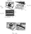
- the slider component 16 is shown in more detail in, and will be further described with reference to, Figs. 5A to 5D .
- Figures 4A and 4B contrast the supply pipe 5 configuration of known assemblies with that of the present disclosure.
- Fig. 4A shows the known manner of fixing the supply pipe 5 to the housing e.g. by solder 26.
- the supply pipe passes freely through the housing 1 and is attached to the slider component 16 within the housing 1.
- the slider component 16 moves within a recess with movement of the jet pipe 7.
- the slider component 16 is provided with a port 25 via which fluid e.g. oil, from the supply channel 24 of the valve assembly, enters the supply pipe 5 for conveyance to the spool 2 via the jet pipe 7 and nozzle as described above.
- the slider component 16 is preferably also provided with seals 17,18.
- the force acting on the armature 4 is, in effect, a reaction force from the fluid exiting the nozzle into the spool 2 and the force of the slider component 16 caused by the friction of the seals 17,81. This results in a greatly reduced loading on the torque motor.
- Fig 3A shows the jet pipe 7 in a centered (non-steered) position. Equal fluid pressure is provided to each end of the spool 2. The slider component 16 thus also remains in the centered position.
- the torque motor causes deflection of the jet pipe 7 to the left, directing more fluid to the left side of the spool 2 via the left channel 10, to push the spool 2 more to the right. Movement of the jet pipe causes corresponding movement of the supply pipe and, hence, the slider component.
- the torque motor causes the jet pipe to move to the right, which causes the spool 2 to move to the left and also causes the slider to move to the left.
- the system of this disclosure avoids bending of the supply pipe when the jet pipe is steered, meaning that a relatively smaller torque motor can be used" which results in reduced size and weight of the assembly as well as more accurate and higher rate control of the valve.
Landscapes
- Engineering & Computer Science (AREA)
- General Engineering & Computer Science (AREA)
- Mechanical Engineering (AREA)
- Physics & Mathematics (AREA)
- Fluid Mechanics (AREA)
- Servomotors (AREA)
Abstract
Description
- The present disclosure relates to servovalves used to transfer quantities of, or manage the flow of fluid e.g. air.
- Servovalves find a wide range of applications for controlling air or other fluid flow to effect driving or control of another part e.g. an actuator.
- A servovalve assembly includes a motor controlled by a control current which controls flow to an air valve to control an actuator. Generally, a servovalve transforms an input control signal into movement of an actuator cylinder. The actuator controls e.g. an air valve. In other words, a servovalve acts as a controller, which commands the actuator, which changes the position of an air valve's (e.g. a so-called butterfly valve's) flow modulating feature.
- Such mechanisms are used, for example, in various parts of aircraft where the management of air/fluid flow is required, such as in engine bleeding systems, anti-ice systems, air conditioning systems and cabin pressure systems. Servovalves are widely used to control the flow and pressure of pneumatic and hydraulic fluids to an actuator, and in applications where accurate position or flow rate control is required.
- Conventionally, servovalve systems operate by obtaining pressurised fluid from a high pressure source which is transmitted through a load from which the fluid is output as a control fluid. Various types of servovalves are known - see e.g.
GB 2104249 US 2015/0047729 andUS 9,309,900 - Electrohydraulic servovalves can have a first stage with a motor, e.g. an electrical or electromagnetic force motor or torque motor, controlling flow of a hydraulic fluid to drive a valve member e.g. a spool valve of a second stage, which, in turn, can control flow of hydraulic fluid to an actuator for driving a load. The motor can operate to position a moveable member, such as a flapper, in response to an input drive signal or control current, to drive the second stage valve member e.g. a spool valve.
- Particularly in aircraft applications, but also in other applications, servovalves are often required to operate at various pressures and temperatures. For e.g. fast acting air valve actuators, relatively large flows are required depending on the size of the actuator and the valve slew rate. For such high flow rates, however, large valve orifice areas are required. For 'flapper' type servovalves, problems arise when dealing with large flows due to the fact that flow force acts in the direction of the flapper movement and the motor is forced to overcome the flow forces. For clevis-like metering valves such as described in
US 4,046,061 andUS 6,786,238 , the flow forces, proportional to the flow, act simultaneously in opposite directions so that the clevis is balanced and centered. The clevis, however, needs to be big due to the requirement for bigger orifices to handle larger flows. - Jet pipe servovalves provide an alternative to 'flapper'- type servovalves. Jet pipe servovalves are usually larger than flapper type servovalves but are less sensitive to contamination. In jet pipe systems, fluid is provided via a jet pipe to a nozzle which directs a stream of fluid at a receiver. When the nozzle is centered - i.e. no current from the motor causes it to turn, the receiver is hit by the stream of fluid from the nozzle at the centre so that the fluid is directed to both ends of the spool equally. If the motor causes the nozzle to turn, the stream of fluid from the nozzle impinges more on one side of the receiver and thus on one side of the spool more than the other causing the spool to shift. The spool shifts until the spring force of a feedback spring produces a torque equal to the motor torque. At this point, the nozzle is centred again, pressure is equal on both sides of the receiver and the spool is held in the centered position. A change in motor current moves the spool to a new position corresponding to the applied current.
- As mentioned above, jet pipe servovalves are advantageous in that they are less sensitive to contamination e.g. in the supply fluid or from the valve environment. These valves are, however, more complex and bulkier. The torque motor that comprises electromagnets to apply electromagnetic force to an armature to move the jet pipe is large and heavy, which adds to the size, weight and complexity of the overall system. Particularly if jet-pipe servovalves are to handle the same high levels of pressure as flapper valves e.g. 31.5MPa or more, while maintaining the accuracy of the valve, larger, more powerful motors are required. The supply pipe torsion tube needs to have thicker walls for higher pressures and, since the motor has to bend the supply pipe when it moves the jet pipe, the motor needs to be stronger.
- There is a need for a jet-pipe servovalve arrangement that is able to operate accurately and reliably, particularly at higher pressures, using a smaller torque motor.
- The present disclosure provides a servovalve comprising: a fluid transfer valve assembly comprising a supply port and a control port; a moveable valve spool arranged to regulate flow of fluid from the supply port to the control port in response to a control signal; and a drive assembly configured to axially move the valve spool relative to the fluid transfer assembly in response to the control signal to regulate the fluid flow; wherein the drive assembly comprises a steerable jet pipe moveable by an amount determined by the control signal to cause corresponding movement of the valve spool; the jet pipe terminating at one end in a nozzle and at the other end being in fluid flow engagement with a fluid supply pipe, whereby movement of the valve spool is caused by fluid flowing from the nozzle to engage with the valve spool, and wherein the end of the supply pipe furthest from the jet pipe is attached to a slider component for sliding movement responsive to movement of the jet pipe responsive to the control signal.
- The fluid transfer valve assembly may also comprise a return port for pressure returning through the assembly.
- In a jet-pipe system, supply fluid is provided from a fluid (e.g. oil) source via the supply pipe, into the jet pipe and out through the nozzle, where it is directed into the valve assembly via a receiver. The receiver is preferably configured such that when the nozzle is in a central position, fluid enters the valve assembly evenly via both sides of the receiver, e.g. by opposing lateral receiver channels. When the nozzle is steered to an off-centre position, more fluid flows to one side of the valve assembly than the other via the receiver; e.g. more flows through one lateral receiver channel than the other.
- Preferred embodiments will now be described with reference to the drawings.
-
-
Fig. 1 is a sectional view of a conventional jet pipe servovalve. -
Fig. 2 is a simplified schematic view of a conventional servovalve. -
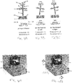
Figs. 3A to 3C show, schematically, operation of a jet-pipe assembly according to this disclosure. -
Fig 4A is a perspective, partially removed, view of a conventional jet pipe assembly. -
Fig 4B is a perspective, partially removed, view of a jet pipe assembly according to this disclosure. -
Figs. 5A to 5D show various views of the slider component features of this disclosure. - A servovalve as described below can, for example, be used in an actuator control system. The servovalve is controlled by a torque motor to control a control flow of fluid that is output via e.g. a butterfly value to control the movement of an actuator.
- With reference to
Figs. 1 and 2 , a conventional jet pipe servovalve will first be described. The arrangement comprises a servovalve assembly have a torque motor and drive assembly having amotor armature 4 and amoveable spool 2 mounted in a supportingblock 15 arranged within anassembly housing 1. Thespool 2 is part of a spool assembly having: supply ports, control ports, and a return port. Flow is possible between the ports via a passage through thespool 2. The torque motor provides current that moves anarmature 4 that causes ajet pipe 7 to turn at its end closest to the spool, which end terminates in a nozzle. Supply fluid is provided from the supply port, via asupply pipe 5, which may include afilter 30, to the top of the jet pipe - i.e. the end opposite the end with the nozzle, and the supply fluid flows through the jet pipe and out of the nozzle. Thesupply pipe 5, also known as a feed tube or a torsion tube, is fixed to the housing where the pipe enters the housing. The other end of the supply pipe is fixed to the jet pipe and/or the armature e.g. by welding 6. Areceiver channels spool 2. When no current is applied by the motor to the jet pipe, the nozzle is centered relative to thereceiver channels spool 2. The spool therefore remains centered - i.e. 'closed' so that no fluid flows through the control ports. When actuator control is desired, the motor provides a control current to the jet pipe via thearmature 4 causing the nozzle to turn away from the centered position. The jet pipe and nozzle are turned due to an electromagnetic force created by electromagnets of the torque motor acting on the armature which acts on the jet pipe. The supply fluid through the nozzle then flows predominantly through onereceiver channel spool 2 causing axial movement of thespool 2 with either blocks/occludes the passage between the supply port and the respective control port or opens the passage to allow flow between the two ports, depending on the axial position of the spool due to the position of the nozzle, thus modulating pressure on the control ports and controlling the actuator (not shown). - In an example, the assembly is arranged to control an actuator based on the fluid flow from the control port e.g. via a butterfly valve. The servovalve controls an actuator which, in turn, controls an air valve such as a butterfly valve.
- Supply pressure is provided to the
spool 2 via spool supply ports. The pressure at return port is atmospheric pressure which will vary depending e.g. on the altitude of the aircraft in flight. Control ports provide a controlled pressure, dependant on the nozzle position and resulting spool position, to be provided to an actuator. Thesupply pipe 5 is also connected to the supply port and routes supply fluid external to thespool 2, preferably via afilter 30, and into the top end of thejet pipe 7. Thesupply fluid 8 flows down thejet pipe 7 to the nozzle and exits to the receiver described above. Thejet pipe 7 is preferably mounted in a flexural tube (not shown). While the nozzle is centered as shown inFig. 2 , equal amounts of fluid go to the two ends of thespool 2. - The
spool 2 is in the form of a tubular member arranged in theblock 15 to be moved axially by fluid from thejet pipe 7 via the nozzle that is directed at thespool 2 via the receiver. - A feedback spring 27 serves to return the nozzle to the centered position.
- In more detail, in the embodiment shown, to open the servovalve, control current is provided to coils of the motor (here a torque motor) creating electromagnetic torque opposing the sum of mechanical and magnetic torque already 'present' in the torque motor. The bigger the electromagnetic force from the coils, the more the jet pipe nozzle turns. The more it turns, the greater the linear or axial movement of the
spool 2. A torque motor usually consists of coil windings, a ferromagnetic armature, permanent magnets and a mechanical spring (here two torsional bridge shafts). This arrangement provides movement of the nozzle proportional to the input control current. Other types of motor could be envisaged. - As mentioned above, the
supply pipe 5 is fixed, e.g. by aweld 6, relative to thesteerable jet pipe 7 and the other end passes into thehousing 1 for connection to the supply port. In the conventional design, thesupply pipe 5 is fixed to thehousing 1 at the point ofentry 60 also e.g. by welding or soldering. - The motor, responsive to the control signal, actuates the
armature 4 to move thejet pipe 7 in one or other direction (in the drawings, left or right) to cause displacement of the nozzle relative to the receiver, as described above. The rigid connection with thesupply pipe 5 causes resulting bending of that pipe because the supply pipe is also fixed to thehousing 1. Bending the supply pipe, which is usually made of metal, absorbs a large amount of the motor's power, meaning that larger motors are required. - In the system of the present disclosure, the
supply pipe 5 is not fixed to thehousing 1. Instead, thesupply pipe 5 passes freely through an opening in thehousing 1 and is attached to aslider component 16 slidingly arranged within thehousing 1. Theslider component 16 is shown in more detail in, and will be further described with reference to,Figs. 5A to 5D . - This enables the jet pipe to be moved or steered without bending the supply pipe, as corresponding movement of the supply pipe is permitted by virtue of the sliding movement of the
slider component 16 to which it is attached. The torque motor is therefore able to operate at lower power. -
Figures 4A and 4B contrast thesupply pipe 5 configuration of known assemblies with that of the present disclosure.Fig. 4A shows the known manner of fixing thesupply pipe 5 to the housing e.g. bysolder 26. In contrast, as seen inFig. 4B , in the present disclosure, the supply pipe passes freely through thehousing 1 and is attached to theslider component 16 within thehousing 1. - As best seen in
Figs. 5A to 5D , theslider component 16 moves within a recess with movement of thejet pipe 7. Theslider component 16 is provided with aport 25 via which fluid e.g. oil, from thesupply channel 24 of the valve assembly, enters thesupply pipe 5 for conveyance to thespool 2 via thejet pipe 7 and nozzle as described above. Theslider component 16 is preferably also provided withseals - The force acting on the
armature 4 is, in effect, a reaction force from the fluid exiting the nozzle into thespool 2 and the force of theslider component 16 caused by the friction of theseals 17,81. This results in a greatly reduced loading on the torque motor. - Operation of the assembly is now briefly described with reference to
Figs. 3A to 3C. Fig 3A shows thejet pipe 7 in a centered (non-steered) position. Equal fluid pressure is provided to each end of thespool 2. Theslider component 16 thus also remains in the centered position. InFig. 3B , the torque motor causes deflection of thejet pipe 7 to the left, directing more fluid to the left side of thespool 2 via theleft channel 10, to push thespool 2 more to the right. Movement of the jet pipe causes corresponding movement of the supply pipe and, hence, the slider component. InFig. 3C , the torque motor causes the jet pipe to move to the right, which causes thespool 2 to move to the left and also causes the slider to move to the left. - Operation of the spool and feedback is otherwise as in conventional systems.
- The system of this disclosure avoids bending of the supply pipe when the jet pipe is steered, meaning that a relatively smaller torque motor can be used" which results in reduced size and weight of the assembly as well as more accurate and higher rate control of the valve.
- Although this disclosure has been described in terms of preferred examples, it should be understood that these examples are illustrative only and modifications and alterations are possible within the scope of the claims.
Claims (7)
- A servovalve comprising: a fluid transfer valve assembly comprising a supply port and a control port; a moveable valve spool arranged to regulate flow of fluid from the supply port to the control port in response to a control signal; and a drive assembly configured to axially move the valve spool relative to the fluid transfer assembly in response to the control signal to regulate the fluid flow; wherein the drive assembly comprises a steerable jet pipe moveable by an amount determined by the control signal to cause corresponding movement of the valve spool; the jet pipe terminating at one end in a nozzle and at the other end being in fluid flow engagement with a fluid supply pipe, whereby movement of the valve spool is caused by fluid flowing from the nozzle to engage with the valve spool, and wherein the end of the supply pipe furthest from the jet pipe is attached to a slider component for sliding movement responsive to movement of the jet pipe responsive to the control signal.
- The servovalve of claim 1, wherein the slider component is mounted within a housing of the fluid transfer assembly.
- The servovalve of claim 1 or 2, wherein the end of the supply pipe is attached to the slider component by welding.
- The servovalve of claim 1, wherein the fluid transfer valve assembly further comprises a return port (16) for pressure returning through the assembly.
- The servovalve of Claim 1, wherein the fluid is directed into the spool from the nozzle via a receiver configured such that when the nozzle is in a central position, fluid enters the valve assembly evenly via both sides of the receiver when the nozzle is steered to an off-centre position, more fluid flows to one side of the valve assembly than the other via the receiver.
- The servovalve of Claim 1, wherein the receiver comprises lateral receiver channels to provide flow to each side of the valve assembly.
- The servovalve of any of claims 1 to 4, wherein the nozzle is provided on the jet pipe mounted within a flexible tube (26'), wherein the tube imparts movement to the jet pipe to steer the nozzle in response to the control signal.
Priority Applications (2)
| Application Number | Priority Date | Filing Date | Title |
|---|---|---|---|
| EP17461546.8A EP3412921B1 (en) | 2017-06-05 | 2017-06-05 | Servovalve assembly |
| US15/928,222 US10544870B2 (en) | 2017-06-05 | 2018-03-22 | Servovalve assembly |
Applications Claiming Priority (1)
| Application Number | Priority Date | Filing Date | Title |
|---|---|---|---|
| EP17461546.8A EP3412921B1 (en) | 2017-06-05 | 2017-06-05 | Servovalve assembly |
Publications (2)
| Publication Number | Publication Date |
|---|---|
| EP3412921A1 true EP3412921A1 (en) | 2018-12-12 |
| EP3412921B1 EP3412921B1 (en) | 2024-03-13 |
Family
ID=59009641
Family Applications (1)
| Application Number | Title | Priority Date | Filing Date |
|---|---|---|---|
| EP17461546.8A Active EP3412921B1 (en) | 2017-06-05 | 2017-06-05 | Servovalve assembly |
Country Status (2)
| Country | Link |
|---|---|
| US (1) | US10544870B2 (en) |
| EP (1) | EP3412921B1 (en) |
Families Citing this family (2)
| Publication number | Priority date | Publication date | Assignee | Title |
|---|---|---|---|---|
| EP3587791B1 (en) * | 2018-06-21 | 2021-03-24 | Claverham Limited | Flow control nozzle |
| EP4194334A1 (en) * | 2021-12-08 | 2023-06-14 | Microtecnica S.r.l. | Stability and control augmentation system |
Citations (10)
| Publication number | Priority date | Publication date | Assignee | Title |
|---|---|---|---|---|
| US3429225A (en) * | 1966-06-09 | 1969-02-25 | Abex Corp | Electrohydraulic displacement control with mechanical feedback |
| US4046061A (en) | 1975-12-03 | 1977-09-06 | The Garrett Corporation | Four-way clevis valve and method |
| EP0012743A1 (en) * | 1978-12-18 | 1980-06-25 | United Technologies Corporation | Piezoelectric control valve |
| GB2104249A (en) | 1981-08-19 | 1983-03-02 | Moog Inc | Servovalves |
| US5156189A (en) * | 1989-09-13 | 1992-10-20 | Hr Textron, Inc. | High flow control valve |
| DE4431600A1 (en) * | 1994-09-05 | 1996-03-07 | Rexroth Mannesmann Gmbh | Jet-pipe stage for servo valve auxiliary or pilot control |
| US6786238B2 (en) | 2002-06-11 | 2004-09-07 | Festo Ag & Co. | Solenoid valve |
| US20150047729A1 (en) | 2012-02-23 | 2015-02-19 | Moog Inc. | Integrated structure electro-hydraulic valve |
| US9309900B2 (en) | 2012-02-09 | 2016-04-12 | Moog Inc. | Electro-hydraulic servo valve |
| EP3242041A1 (en) * | 2016-05-03 | 2017-11-08 | Zodiac Hydraulics | Servo valve with asymmetric redundant piezoelectric actuator |
Family Cites Families (9)
| Publication number | Priority date | Publication date | Assignee | Title |
|---|---|---|---|---|
| US3282283A (en) * | 1963-12-23 | 1966-11-01 | Gocko Regulator Co Ltd | Hydraulic regulating system and apparatus |
| US3584638A (en) * | 1969-06-13 | 1971-06-15 | Bell Aerospace Corp | Adjustable receiver port construction for jet pipe servovalve |
| US4510848A (en) | 1982-09-30 | 1985-04-16 | General Electric Company | Shear-type fail-fixed servovalve |
| CN201439840U (en) | 2008-12-19 | 2010-04-21 | 上海诺玛液压系统有限公司 | Moment motor jet tube pilot valve |
| FR2963393B1 (en) * | 2010-07-29 | 2014-02-14 | In Lhc | SERVOVALVE PILOTAGE STAGE, WHICH CAN SERVE AS A FIRST FLOOR IN A SERVOVALVE WITH TWO FLOORS. |
| FR2981133B1 (en) | 2011-10-10 | 2013-10-25 | In Lhc | METHOD OF DETECTING FAILURE OF SERVOVALVE AND SERVOVALVE APPLYING. |
| GB2516693A (en) | 2013-07-30 | 2015-02-04 | Moog Controls Ltd | Improvements in hydraulic servovalves |
| FR3024505B1 (en) * | 2014-07-31 | 2016-08-05 | Zodiac Hydraulics | SERVOVALVE WITH DOUBLE MOBILE ASSEMBLY |
| US9574676B2 (en) | 2015-01-23 | 2017-02-21 | Honeywell International Inc. | High-temperature and high-vibration capable armature assemblies for torque motor valve actuators |
-
2017
- 2017-06-05 EP EP17461546.8A patent/EP3412921B1/en active Active
-
2018
- 2018-03-22 US US15/928,222 patent/US10544870B2/en active Active
Patent Citations (10)
| Publication number | Priority date | Publication date | Assignee | Title |
|---|---|---|---|---|
| US3429225A (en) * | 1966-06-09 | 1969-02-25 | Abex Corp | Electrohydraulic displacement control with mechanical feedback |
| US4046061A (en) | 1975-12-03 | 1977-09-06 | The Garrett Corporation | Four-way clevis valve and method |
| EP0012743A1 (en) * | 1978-12-18 | 1980-06-25 | United Technologies Corporation | Piezoelectric control valve |
| GB2104249A (en) | 1981-08-19 | 1983-03-02 | Moog Inc | Servovalves |
| US5156189A (en) * | 1989-09-13 | 1992-10-20 | Hr Textron, Inc. | High flow control valve |
| DE4431600A1 (en) * | 1994-09-05 | 1996-03-07 | Rexroth Mannesmann Gmbh | Jet-pipe stage for servo valve auxiliary or pilot control |
| US6786238B2 (en) | 2002-06-11 | 2004-09-07 | Festo Ag & Co. | Solenoid valve |
| US9309900B2 (en) | 2012-02-09 | 2016-04-12 | Moog Inc. | Electro-hydraulic servo valve |
| US20150047729A1 (en) | 2012-02-23 | 2015-02-19 | Moog Inc. | Integrated structure electro-hydraulic valve |
| EP3242041A1 (en) * | 2016-05-03 | 2017-11-08 | Zodiac Hydraulics | Servo valve with asymmetric redundant piezoelectric actuator |
Also Published As
| Publication number | Publication date |
|---|---|
| US10544870B2 (en) | 2020-01-28 |
| US20180347712A1 (en) | 2018-12-06 |
| EP3412921B1 (en) | 2024-03-13 |
Similar Documents
| Publication | Publication Date | Title |
|---|---|---|
| EP3418586B1 (en) | Servovalve | |
| EP3321513B1 (en) | Servovalve | |
| EP3660368B1 (en) | Servo valve | |
| EP3284956B1 (en) | Servovalve | |
| EP3409952B1 (en) | Servovalve | |
| US10598297B2 (en) | Servovalve | |
| US10544870B2 (en) | Servovalve assembly | |
| US10760704B2 (en) | Servovalve assembly | |
| US11732819B2 (en) | Servo valve | |
| EP4194705B1 (en) | Flapper servo valve | |
| EP3431780B1 (en) | Servovalve | |
| EP4438910A1 (en) | Servovalve | |
| EP3626978A1 (en) | Servovalve | |
| US11050333B2 (en) | Torque motor assembly |
Legal Events
| Date | Code | Title | Description |
|---|---|---|---|
| PUAI | Public reference made under article 153(3) epc to a published international application that has entered the european phase |
Free format text: ORIGINAL CODE: 0009012 |
|
| STAA | Information on the status of an ep patent application or granted ep patent |
Free format text: STATUS: THE APPLICATION HAS BEEN PUBLISHED |
|
| AK | Designated contracting states |
Kind code of ref document: A1 Designated state(s): AL AT BE BG CH CY CZ DE DK EE ES FI FR GB GR HR HU IE IS IT LI LT LU LV MC MK MT NL NO PL PT RO RS SE SI SK SM TR |
|
| AX | Request for extension of the european patent |
Extension state: BA ME |
|
| STAA | Information on the status of an ep patent application or granted ep patent |
Free format text: STATUS: REQUEST FOR EXAMINATION WAS MADE |
|
| 17P | Request for examination filed |
Effective date: 20190612 |
|
| RBV | Designated contracting states (corrected) |
Designated state(s): AL AT BE BG CH CY CZ DE DK EE ES FI FR GB GR HR HU IE IS IT LI LT LU LV MC MK MT NL NO PL PT RO RS SE SI SK SM TR |
|
| STAA | Information on the status of an ep patent application or granted ep patent |
Free format text: STATUS: EXAMINATION IS IN PROGRESS |
|
| 17Q | First examination report despatched |
Effective date: 20210510 |
|
| GRAP | Despatch of communication of intention to grant a patent |
Free format text: ORIGINAL CODE: EPIDOSNIGR1 |
|
| STAA | Information on the status of an ep patent application or granted ep patent |
Free format text: STATUS: GRANT OF PATENT IS INTENDED |
|
| INTG | Intention to grant announced |
Effective date: 20231004 |
|
| RIN1 | Information on inventor provided before grant (corrected) |
Inventor name: JASKIEWICZ, ZBIGNIEW |
|
| GRAS | Grant fee paid |
Free format text: ORIGINAL CODE: EPIDOSNIGR3 |
|
| GRAA | (expected) grant |
Free format text: ORIGINAL CODE: 0009210 |
|
| STAA | Information on the status of an ep patent application or granted ep patent |
Free format text: STATUS: THE PATENT HAS BEEN GRANTED |
|
| AK | Designated contracting states |
Kind code of ref document: B1 Designated state(s): AL AT BE BG CH CY CZ DE DK EE ES FI FR GB GR HR HU IE IS IT LI LT LU LV MC MK MT NL NO PL PT RO RS SE SI SK SM TR |
|
| REG | Reference to a national code |
Ref country code: GB Ref legal event code: FG4D |
|
| REG | Reference to a national code |
Ref country code: CH Ref legal event code: EP |
|
| REG | Reference to a national code |
Ref country code: DE Ref legal event code: R096 Ref document number: 602017079944 Country of ref document: DE |
|
| REG | Reference to a national code |
Ref country code: IE Ref legal event code: FG4D |
|
| PG25 | Lapsed in a contracting state [announced via postgrant information from national office to epo] |
Ref country code: LT Free format text: LAPSE BECAUSE OF FAILURE TO SUBMIT A TRANSLATION OF THE DESCRIPTION OR TO PAY THE FEE WITHIN THE PRESCRIBED TIME-LIMIT Effective date: 20240313 |
|
| REG | Reference to a national code |
Ref country code: LT Ref legal event code: MG9D |
|
| PG25 | Lapsed in a contracting state [announced via postgrant information from national office to epo] |
Ref country code: GR Free format text: LAPSE BECAUSE OF FAILURE TO SUBMIT A TRANSLATION OF THE DESCRIPTION OR TO PAY THE FEE WITHIN THE PRESCRIBED TIME-LIMIT Effective date: 20240614 |
|
| REG | Reference to a national code |
Ref country code: NL Ref legal event code: MP Effective date: 20240313 |
|
| PG25 | Lapsed in a contracting state [announced via postgrant information from national office to epo] |
Ref country code: HR Free format text: LAPSE BECAUSE OF FAILURE TO SUBMIT A TRANSLATION OF THE DESCRIPTION OR TO PAY THE FEE WITHIN THE PRESCRIBED TIME-LIMIT Effective date: 20240313 Ref country code: RS Free format text: LAPSE BECAUSE OF FAILURE TO SUBMIT A TRANSLATION OF THE DESCRIPTION OR TO PAY THE FEE WITHIN THE PRESCRIBED TIME-LIMIT Effective date: 20240613 |
|
| PG25 | Lapsed in a contracting state [announced via postgrant information from national office to epo] |
Ref country code: ES Free format text: LAPSE BECAUSE OF FAILURE TO SUBMIT A TRANSLATION OF THE DESCRIPTION OR TO PAY THE FEE WITHIN THE PRESCRIBED TIME-LIMIT Effective date: 20240313 |
|
| PG25 | Lapsed in a contracting state [announced via postgrant information from national office to epo] |
Ref country code: RS Free format text: LAPSE BECAUSE OF FAILURE TO SUBMIT A TRANSLATION OF THE DESCRIPTION OR TO PAY THE FEE WITHIN THE PRESCRIBED TIME-LIMIT Effective date: 20240613 Ref country code: NO Free format text: LAPSE BECAUSE OF FAILURE TO SUBMIT A TRANSLATION OF THE DESCRIPTION OR TO PAY THE FEE WITHIN THE PRESCRIBED TIME-LIMIT Effective date: 20240613 Ref country code: LT Free format text: LAPSE BECAUSE OF FAILURE TO SUBMIT A TRANSLATION OF THE DESCRIPTION OR TO PAY THE FEE WITHIN THE PRESCRIBED TIME-LIMIT Effective date: 20240313 Ref country code: HR Free format text: LAPSE BECAUSE OF FAILURE TO SUBMIT A TRANSLATION OF THE DESCRIPTION OR TO PAY THE FEE WITHIN THE PRESCRIBED TIME-LIMIT Effective date: 20240313 Ref country code: GR Free format text: LAPSE BECAUSE OF FAILURE TO SUBMIT A TRANSLATION OF THE DESCRIPTION OR TO PAY THE FEE WITHIN THE PRESCRIBED TIME-LIMIT Effective date: 20240614 Ref country code: FI Free format text: LAPSE BECAUSE OF FAILURE TO SUBMIT A TRANSLATION OF THE DESCRIPTION OR TO PAY THE FEE WITHIN THE PRESCRIBED TIME-LIMIT Effective date: 20240313 Ref country code: ES Free format text: LAPSE BECAUSE OF FAILURE TO SUBMIT A TRANSLATION OF THE DESCRIPTION OR TO PAY THE FEE WITHIN THE PRESCRIBED TIME-LIMIT Effective date: 20240313 Ref country code: BG Free format text: LAPSE BECAUSE OF FAILURE TO SUBMIT A TRANSLATION OF THE DESCRIPTION OR TO PAY THE FEE WITHIN THE PRESCRIBED TIME-LIMIT Effective date: 20240313 |
|
| REG | Reference to a national code |
Ref country code: AT Ref legal event code: MK05 Ref document number: 1666007 Country of ref document: AT Kind code of ref document: T Effective date: 20240313 |
|
| PG25 | Lapsed in a contracting state [announced via postgrant information from national office to epo] |
Ref country code: SE Free format text: LAPSE BECAUSE OF FAILURE TO SUBMIT A TRANSLATION OF THE DESCRIPTION OR TO PAY THE FEE WITHIN THE PRESCRIBED TIME-LIMIT Effective date: 20240313 Ref country code: LV Free format text: LAPSE BECAUSE OF FAILURE TO SUBMIT A TRANSLATION OF THE DESCRIPTION OR TO PAY THE FEE WITHIN THE PRESCRIBED TIME-LIMIT Effective date: 20240313 |
|
| PG25 | Lapsed in a contracting state [announced via postgrant information from national office to epo] |
Ref country code: NL Free format text: LAPSE BECAUSE OF FAILURE TO SUBMIT A TRANSLATION OF THE DESCRIPTION OR TO PAY THE FEE WITHIN THE PRESCRIBED TIME-LIMIT Effective date: 20240313 |
|
| PG25 | Lapsed in a contracting state [announced via postgrant information from national office to epo] |
Ref country code: NL Free format text: LAPSE BECAUSE OF FAILURE TO SUBMIT A TRANSLATION OF THE DESCRIPTION OR TO PAY THE FEE WITHIN THE PRESCRIBED TIME-LIMIT Effective date: 20240313 |
|
| PG25 | Lapsed in a contracting state [announced via postgrant information from national office to epo] |
Ref country code: IS Free format text: LAPSE BECAUSE OF FAILURE TO SUBMIT A TRANSLATION OF THE DESCRIPTION OR TO PAY THE FEE WITHIN THE PRESCRIBED TIME-LIMIT Effective date: 20240713 |
|
| PG25 | Lapsed in a contracting state [announced via postgrant information from national office to epo] |
Ref country code: PT Free format text: LAPSE BECAUSE OF FAILURE TO SUBMIT A TRANSLATION OF THE DESCRIPTION OR TO PAY THE FEE WITHIN THE PRESCRIBED TIME-LIMIT Effective date: 20240715 Ref country code: SM Free format text: LAPSE BECAUSE OF FAILURE TO SUBMIT A TRANSLATION OF THE DESCRIPTION OR TO PAY THE FEE WITHIN THE PRESCRIBED TIME-LIMIT Effective date: 20240313 |
|
| PG25 | Lapsed in a contracting state [announced via postgrant information from national office to epo] |
Ref country code: EE Free format text: LAPSE BECAUSE OF FAILURE TO SUBMIT A TRANSLATION OF THE DESCRIPTION OR TO PAY THE FEE WITHIN THE PRESCRIBED TIME-LIMIT Effective date: 20240313 Ref country code: CZ Free format text: LAPSE BECAUSE OF FAILURE TO SUBMIT A TRANSLATION OF THE DESCRIPTION OR TO PAY THE FEE WITHIN THE PRESCRIBED TIME-LIMIT Effective date: 20240313 |
|
| PG25 | Lapsed in a contracting state [announced via postgrant information from national office to epo] |
Ref country code: AT Free format text: LAPSE BECAUSE OF FAILURE TO SUBMIT A TRANSLATION OF THE DESCRIPTION OR TO PAY THE FEE WITHIN THE PRESCRIBED TIME-LIMIT Effective date: 20240313 |
|
| PG25 | Lapsed in a contracting state [announced via postgrant information from national office to epo] |
Ref country code: PL Free format text: LAPSE BECAUSE OF FAILURE TO SUBMIT A TRANSLATION OF THE DESCRIPTION OR TO PAY THE FEE WITHIN THE PRESCRIBED TIME-LIMIT Effective date: 20240313 |
|
| PG25 | Lapsed in a contracting state [announced via postgrant information from national office to epo] |
Ref country code: SK Free format text: LAPSE BECAUSE OF FAILURE TO SUBMIT A TRANSLATION OF THE DESCRIPTION OR TO PAY THE FEE WITHIN THE PRESCRIBED TIME-LIMIT Effective date: 20240313 |
|
| PG25 | Lapsed in a contracting state [announced via postgrant information from national office to epo] |
Ref country code: SM Free format text: LAPSE BECAUSE OF FAILURE TO SUBMIT A TRANSLATION OF THE DESCRIPTION OR TO PAY THE FEE WITHIN THE PRESCRIBED TIME-LIMIT Effective date: 20240313 Ref country code: SK Free format text: LAPSE BECAUSE OF FAILURE TO SUBMIT A TRANSLATION OF THE DESCRIPTION OR TO PAY THE FEE WITHIN THE PRESCRIBED TIME-LIMIT Effective date: 20240313 Ref country code: RO Free format text: LAPSE BECAUSE OF FAILURE TO SUBMIT A TRANSLATION OF THE DESCRIPTION OR TO PAY THE FEE WITHIN THE PRESCRIBED TIME-LIMIT Effective date: 20240313 Ref country code: PT Free format text: LAPSE BECAUSE OF FAILURE TO SUBMIT A TRANSLATION OF THE DESCRIPTION OR TO PAY THE FEE WITHIN THE PRESCRIBED TIME-LIMIT Effective date: 20240715 Ref country code: PL Free format text: LAPSE BECAUSE OF FAILURE TO SUBMIT A TRANSLATION OF THE DESCRIPTION OR TO PAY THE FEE WITHIN THE PRESCRIBED TIME-LIMIT Effective date: 20240313 Ref country code: IS Free format text: LAPSE BECAUSE OF FAILURE TO SUBMIT A TRANSLATION OF THE DESCRIPTION OR TO PAY THE FEE WITHIN THE PRESCRIBED TIME-LIMIT Effective date: 20240713 Ref country code: EE Free format text: LAPSE BECAUSE OF FAILURE TO SUBMIT A TRANSLATION OF THE DESCRIPTION OR TO PAY THE FEE WITHIN THE PRESCRIBED TIME-LIMIT Effective date: 20240313 Ref country code: CZ Free format text: LAPSE BECAUSE OF FAILURE TO SUBMIT A TRANSLATION OF THE DESCRIPTION OR TO PAY THE FEE WITHIN THE PRESCRIBED TIME-LIMIT Effective date: 20240313 Ref country code: AT Free format text: LAPSE BECAUSE OF FAILURE TO SUBMIT A TRANSLATION OF THE DESCRIPTION OR TO PAY THE FEE WITHIN THE PRESCRIBED TIME-LIMIT Effective date: 20240313 |
|
| PG25 | Lapsed in a contracting state [announced via postgrant information from national office to epo] |
Ref country code: IT Free format text: LAPSE BECAUSE OF FAILURE TO SUBMIT A TRANSLATION OF THE DESCRIPTION OR TO PAY THE FEE WITHIN THE PRESCRIBED TIME-LIMIT Effective date: 20240313 |
|
| REG | Reference to a national code |
Ref country code: DE Ref legal event code: R097 Ref document number: 602017079944 Country of ref document: DE |
|
| PG25 | Lapsed in a contracting state [announced via postgrant information from national office to epo] |
Ref country code: IT Free format text: LAPSE BECAUSE OF FAILURE TO SUBMIT A TRANSLATION OF THE DESCRIPTION OR TO PAY THE FEE WITHIN THE PRESCRIBED TIME-LIMIT Effective date: 20240313 |
|
| PG25 | Lapsed in a contracting state [announced via postgrant information from national office to epo] |
Ref country code: DK Free format text: LAPSE BECAUSE OF FAILURE TO SUBMIT A TRANSLATION OF THE DESCRIPTION OR TO PAY THE FEE WITHIN THE PRESCRIBED TIME-LIMIT Effective date: 20240313 |
|
| PLBE | No opposition filed within time limit |
Free format text: ORIGINAL CODE: 0009261 |
|
| STAA | Information on the status of an ep patent application or granted ep patent |
Free format text: STATUS: NO OPPOSITION FILED WITHIN TIME LIMIT |
|
| PG25 | Lapsed in a contracting state [announced via postgrant information from national office to epo] |
Ref country code: DK Free format text: LAPSE BECAUSE OF FAILURE TO SUBMIT A TRANSLATION OF THE DESCRIPTION OR TO PAY THE FEE WITHIN THE PRESCRIBED TIME-LIMIT Effective date: 20240313 Ref country code: MC Free format text: LAPSE BECAUSE OF FAILURE TO SUBMIT A TRANSLATION OF THE DESCRIPTION OR TO PAY THE FEE WITHIN THE PRESCRIBED TIME-LIMIT Effective date: 20240313 |
|
| REG | Reference to a national code |
Ref country code: CH Ref legal event code: PL |
|
| PG25 | Lapsed in a contracting state [announced via postgrant information from national office to epo] |
Ref country code: LU Free format text: LAPSE BECAUSE OF NON-PAYMENT OF DUE FEES Effective date: 20240605 |
|
| 26N | No opposition filed |
Effective date: 20241216 |
|
| PG25 | Lapsed in a contracting state [announced via postgrant information from national office to epo] |
Ref country code: IE Free format text: LAPSE BECAUSE OF NON-PAYMENT OF DUE FEES Effective date: 20240605 |
|
| PG25 | Lapsed in a contracting state [announced via postgrant information from national office to epo] |
Ref country code: SI Free format text: LAPSE BECAUSE OF FAILURE TO SUBMIT A TRANSLATION OF THE DESCRIPTION OR TO PAY THE FEE WITHIN THE PRESCRIBED TIME-LIMIT Effective date: 20240313 Ref country code: CH Free format text: LAPSE BECAUSE OF NON-PAYMENT OF DUE FEES Effective date: 20240630 Ref country code: BE Free format text: LAPSE BECAUSE OF NON-PAYMENT OF DUE FEES Effective date: 20240630 |
|
| REG | Reference to a national code |
Ref country code: BE Ref legal event code: MM Effective date: 20240630 |
|
| PGFP | Annual fee paid to national office [announced via postgrant information from national office to epo] |
Ref country code: DE Payment date: 20250520 Year of fee payment: 9 |
|
| PGFP | Annual fee paid to national office [announced via postgrant information from national office to epo] |
Ref country code: GB Payment date: 20250520 Year of fee payment: 9 |
|
| PGFP | Annual fee paid to national office [announced via postgrant information from national office to epo] |
Ref country code: FR Payment date: 20250521 Year of fee payment: 9 |
|
| PG25 | Lapsed in a contracting state [announced via postgrant information from national office to epo] |
Ref country code: CY Free format text: LAPSE BECAUSE OF FAILURE TO SUBMIT A TRANSLATION OF THE DESCRIPTION OR TO PAY THE FEE WITHIN THE PRESCRIBED TIME-LIMIT; INVALID AB INITIO Effective date: 20170605 |
|
| PG25 | Lapsed in a contracting state [announced via postgrant information from national office to epo] |
Ref country code: HU Free format text: LAPSE BECAUSE OF FAILURE TO SUBMIT A TRANSLATION OF THE DESCRIPTION OR TO PAY THE FEE WITHIN THE PRESCRIBED TIME-LIMIT; INVALID AB INITIO Effective date: 20170605 |