EP3412874A1 - Axially divided turboengine inner race - Google Patents
Axially divided turboengine inner race Download PDFInfo
- Publication number
- EP3412874A1 EP3412874A1 EP18171212.6A EP18171212A EP3412874A1 EP 3412874 A1 EP3412874 A1 EP 3412874A1 EP 18171212 A EP18171212 A EP 18171212A EP 3412874 A1 EP3412874 A1 EP 3412874A1
- Authority
- EP
- European Patent Office
- Prior art keywords
- ring
- partial
- inner ring
- support surfaces
- partial ring
- Prior art date
- Legal status (The legal status is an assumption and is not a legal conclusion. Google has not performed a legal analysis and makes no representation as to the accuracy of the status listed.)
- Withdrawn
Links
Images
Classifications
-
- F—MECHANICAL ENGINEERING; LIGHTING; HEATING; WEAPONS; BLASTING
- F01—MACHINES OR ENGINES IN GENERAL; ENGINE PLANTS IN GENERAL; STEAM ENGINES
- F01D—NON-POSITIVE DISPLACEMENT MACHINES OR ENGINES, e.g. STEAM TURBINES
- F01D11/00—Preventing or minimising internal leakage of working-fluid, e.g. between stages
- F01D11/001—Preventing or minimising internal leakage of working-fluid, e.g. between stages for sealing space between stator blade and rotor
-
- F—MECHANICAL ENGINEERING; LIGHTING; HEATING; WEAPONS; BLASTING
- F01—MACHINES OR ENGINES IN GENERAL; ENGINE PLANTS IN GENERAL; STEAM ENGINES
- F01D—NON-POSITIVE DISPLACEMENT MACHINES OR ENGINES, e.g. STEAM TURBINES
- F01D25/00—Component parts, details, or accessories, not provided for in, or of interest apart from, other groups
- F01D25/24—Casings; Casing parts, e.g. diaphragms, casing fastenings
- F01D25/246—Fastening of diaphragms or stator-rings
-
- F—MECHANICAL ENGINEERING; LIGHTING; HEATING; WEAPONS; BLASTING
- F01—MACHINES OR ENGINES IN GENERAL; ENGINE PLANTS IN GENERAL; STEAM ENGINES
- F01D—NON-POSITIVE DISPLACEMENT MACHINES OR ENGINES, e.g. STEAM TURBINES
- F01D9/00—Stators
- F01D9/02—Nozzles; Nozzle boxes; Stator blades; Guide conduits, e.g. individual nozzles
- F01D9/04—Nozzles; Nozzle boxes; Stator blades; Guide conduits, e.g. individual nozzles forming ring or sector
- F01D9/042—Nozzles; Nozzle boxes; Stator blades; Guide conduits, e.g. individual nozzles forming ring or sector fixing blades to stators
-
- F—MECHANICAL ENGINEERING; LIGHTING; HEATING; WEAPONS; BLASTING
- F05—INDEXING SCHEMES RELATING TO ENGINES OR PUMPS IN VARIOUS SUBCLASSES OF CLASSES F01-F04
- F05D—INDEXING SCHEME FOR ASPECTS RELATING TO NON-POSITIVE-DISPLACEMENT MACHINES OR ENGINES, GAS-TURBINES OR JET-PROPULSION PLANTS
- F05D2230/00—Manufacture
- F05D2230/60—Assembly methods
- F05D2230/64—Assembly methods using positioning or alignment devices for aligning or centring, e.g. pins
- F05D2230/644—Assembly methods using positioning or alignment devices for aligning or centring, e.g. pins for adjusting the position or the alignment, e.g. wedges or eccenters
-
- F—MECHANICAL ENGINEERING; LIGHTING; HEATING; WEAPONS; BLASTING
- F05—INDEXING SCHEMES RELATING TO ENGINES OR PUMPS IN VARIOUS SUBCLASSES OF CLASSES F01-F04
- F05D—INDEXING SCHEME FOR ASPECTS RELATING TO NON-POSITIVE-DISPLACEMENT MACHINES OR ENGINES, GAS-TURBINES OR JET-PROPULSION PLANTS
- F05D2240/00—Components
- F05D2240/10—Stators
- F05D2240/12—Fluid guiding means, e.g. vanes
-
- F—MECHANICAL ENGINEERING; LIGHTING; HEATING; WEAPONS; BLASTING
- F05—INDEXING SCHEMES RELATING TO ENGINES OR PUMPS IN VARIOUS SUBCLASSES OF CLASSES F01-F04
- F05D—INDEXING SCHEME FOR ASPECTS RELATING TO NON-POSITIVE-DISPLACEMENT MACHINES OR ENGINES, GAS-TURBINES OR JET-PROPULSION PLANTS
- F05D2260/00—Function
- F05D2260/30—Retaining components in desired mutual position
Definitions
- the present invention relates to an axially divided inner ring for attachment to, in particular adjustable, vanes of a turbomachine, in particular a compressor or turbine stage of a gas turbine, a guide grid and a turbomachine, in particular gas turbine, with the inner ring and method for its production and assembly.
- An object of an embodiment of the present invention is to improve an axially split inner ring.
- Claims 12-15 provide protection for a guide grid and a turbomachine with (at least) an inner ring described here, or a method for producing or mounting an inner ring described here.
- Advantageous embodiments of the invention are the subject of the dependent claims.
- the functionality of a screw the two sub-rings set both in the radial direction and in the axial direction to each other, distributed to the dowel pins and the support.
- the assembly improves, reduces the installation space and / or the reliability, in particular strength, of the connection can be improved.
- the directional indication "axial” refers in a usual way to a direction parallel to a rotational or (main) machine axis of the turbomachine
- the direction indication “circumferential direction” corresponds to a direction of rotation about this rotation or (main) machine axis
- the second partial ring is or is clamped in the axial direction between the two mutually facing support surfaces of the first partial ring, in particular elastically.
- the second part-ring has at least one, in particular radially inner or inner, annular or circumferential groove for reducing its rigidity in the axial direction, which is communicated or connected in a further development with at least one recess into which one of the dowel pins is plugged in.
- an assembly and / or clamping of the second partial ring and / or a production of the recess (s) can be improved.
- the second part-ring in particular with support surfaces, contacts the two mutually facing support surfaces of the first part-ring or lies directly or directly against it, in an embodiment with an interference fit or under prestress.
- the second sub-ring by the or between the two support surfaces contacting it, in particular elastic, compressed and thereby clamped, in particular by an axial distance or an axial clearance between the support surfaces is shorter than an axial distance of these contacting support surfaces of the second sub-ring or a wall thickness of the second sub-ring between the two support surfaces with undeformed second part ring.
- the second partial ring is shrunk or clamped with a shrink fit between the two mutually facing support surfaces of the first partial ring, in particular by the first and / or second partial ring for assembly corresponding, in particular different, tempered, in particular cooled or warmed up, becoming or becoming.
- play in the axial direction can be reduced or avoided and / or the fixation by the dowel pins in the radial direction can be assisted or relieved of frictional engagement.
- spring means in particular a one or more parts, in particular beveled and / or curved, spring plate arranged
- at least partially (engaging) in a groove (s) in the first part ring and / or a groove in the second part ring by which the second part ring between the mutually facing support surfaces of the first part ring, in particular elastically, is braced or is and over which the second sub-ring indirectly supported on the corresponding one of the two mutually facing support surfaces of the first sub-ring in the axial direction.
- an assembly and / or disassembly can be improved, in particular in comparison to a contact of the partial ring with two mutually facing support surfaces.
- the second sub-ring is supported in the axial direction directly with its supporting surfaces contacting the two axially facing support surfaces.
- the second partial ring is supported in the axial direction on one or both support surfaces indirectly via (in each case) a one- or multi-part spring means.
- a single- or multi-layer intermediate layer may be arranged or, in particular these embodiments or power flows as a support in the axial direction of the or the ( respective) support surface (s) of the first partial ring in the context of the present invention.
- a dowel pin in one embodiment can be unilaterally secured in the axial direction or be.
- a passage recess assembly can be improved in one embodiment.
- One or more, in particular all, dowel pins are smooth or threadless in one embodiment or are or are not bolted to the first and / or second part ring.
- compared to a screw assembly improves the installation, reduces the space and / or reliability, in particular strength, the connection can be improved.
- one or more, in particular all, dowel pins are secured in the axial direction by a, in particular mono- or multi-part, securing means, in particular one-way, which is attached to one or both partial rings, in particular by frictional engagement, in particular by a single or multi-part, in particular bevelled and / or curved, locking plate or a one-part or multi-part wedge-like securing element or a one or more parts Securing wedge, which in one embodiment at least partially (engaging) in at least one (r) groove in the first part ring and / or at least one (r) groove in the second part ring, arranged, in particular frictionally engaged therein is or is.
- a, in particular mono- or multi-part, securing means in particular one-way, which is attached to one or both partial rings, in particular by frictional engagement, in particular by a single or multi-part, in particular bevelled and / or curved, locking plate or a one-part or multi-part wedge-like securing element or
- the likelihood of damage to the turbomachine can be reduced.
- the securing means may comprise the spring means, in particular at the same time be the spring means.
- the wedge-like securing means or the securing wedge in particular one or more parts of the securing wedge respectively, has a wall thickness increasing or decreasing in the circumferential direction.
- the wedge-like securing means or the securing wedge can advantageously be fixed by friction in the groove (s).
- the locking plate or the securing wedge is inserted in the circumferential direction in the groove (s). As a result, in one embodiment, the assembly can be facilitated.
- the determination supported by the dowel pins in the radial direction and / or assembly can be improved.
- the (end) flange is arranged in an embodiment frontally on the first part of the ring, he can in particular limit or complete the opposite surface of the first part of the ring.
- the flange or collar between one end face and the other of the two support surfaces is arranged, in particular on the mating surface of the first part ring.
- At least one of the support surfaces in a radially extending or radial groove, in particular annular or circumferential groove of the first partial ring is arranged, in particular formed, in particular in the groove in which the spring means is at least partially disposed or in which it intervenes.
- At least one of the support surfaces is flat and / or at least one of the support surfaces is curved.
- the first and / or second partial ring is / are or are segmented in the circumferential direction, in particular in two halves.
- a production and / or assembly can be improved.
- the inner ring has a, in particular integrally formed with the first and / or second part ring or on the first and / or second part ring, in particular non-destructive releasably, in particular materially, or non-destructively detachable, in particular friction and / or form-fitting, fixed , one or multi-part radial seal, which is arranged in a version radially inward on the inner or partial ring.
- the inner ring can thus be in one embodiment in particular a sealing ring or seal carrier.
- the first and second sub-rings form or limit blind-hole-like or through-recesses, in particular, bores in which the guide vanes are fastened, in particular cones of the guide vanes mounted directly or via bushings.
- there is a parting plane of the first and second part ring in one embodiment at least substantially symmetrical, in or through these recesses, in particular a contact plane between one of the support surfaces of the first part ring and a support surface of the second part ring resting thereon.
- a production and / or assembly can be improved.
- the cones of the guide vanes, the bushings and / or the first and / or second sub-ring, in particular the blind-hole-like or passage recesses are at least partially coated. In this way, in one embodiment, a bearing, in particular adjustment, of the guide vanes can be improved.
- the first and / or second part ring in particular material removal, in particular-removing, in particular machined, machined, in particular (the) recesses for the dowel pins and / or vanes manufactured, in particular finished, and / or the first and / or second sub-segment segmented, while at least one, in particular finished, the support surfaces of the first sub-ring and one, in particular finished, supporting surface of the second sub-ring are arranged and pressed against each other in the axial direction against each other or are.
- the two partial rings can be released from each other again, attached to the guide vanes and thereby connected by the dowel pins.
- the second part ring in the axial direction between the two mutually facing support surfaces of the first part ring elastically clamped, in particular by shrinking or the or arranging the spring means (s), and, in particular before, simultaneously or subsequently, fixed in the radial direction by the dowel pins on the first part ring.
- the two partial rings are displaced in the opposite direction to each other in the axial direction and at least partially surround the guide vanes, in particular their bearing journal.
- a production, assembly and / or dimensional stability can be improved.
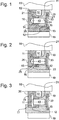
- Fig. 1 shows a part of a guide grid of a turbomachine with an inner ring according to an embodiment of the present invention in a meridian section in which a (main) machine axis (horizontally in Fig. 1 ) lies.
- the inner ring has a first partial ring 10 and a second partial ring 20 and is thus axially or in the axial direction (horizontally in FIG Fig. 1 ) (two) shared. In the circumferential direction is or are the inner ring or the partial rings 10, 20 (each) segmented in two halves.
- a radial seal 19 is arranged.
- the first and second part ring 10, 20 together form blind hole-like holes 52, in which pins 51 are rotatably supported by adjustable vanes 50, in one embodiment directly, in another embodiment via sockets (not shown).
- the second partial ring 20 is in the radial direction (vertically in Fig. 1 ) fixed by a plurality of circumferentially distributed dowel pins 40 on the first part of the ring 10, the frictionally engaged in through holes 24 in the second part of ring 20 and partially inserted through this in blind hole-like holes 14 in the first part ring 10.
- the second partial ring 20 is supported in the axial direction on two axially facing support surfaces 11, 12 of the first partial ring 10, wherein the support surface 12 is arranged in a radial groove 13 of the first partial ring 10.
- a support surface 21 of the second sub-ring 20 contacts the support surface 11 of the first sub-ring 10, while between the second sub-ring 20 and the other support surfaces 12, a spring means 30 is arranged, through or over which the second sub-ring 20 in the axial direction at the other Supporting surface 12 of the two axially facing support surfaces 11, 12 of the first partial ring 10 is supported and thereby clamped between them in the axial direction.
- This spring means 30 is partially arranged in the groove 13 of the first partial ring 10 and partially in a groove 23 of the second partial ring 20 or frictionally secured and thus acts at the same time as a securing means that secures the dowel pins 40 in the axial direction.
- a support surface 25 of the second partial ring 20 is located radially outward (from above in FIG Fig. 1 ) on a mating surface 15 of the first part ring 10.
- the support surface 11 and counter surface 15 of the first part ring 10 and the support surface 21 and support surface 25 of the second part ring 20 are first finished, arranged on each other and both partial rings 10, 20 clamped together in the axial direction by means not shown clamping means, so that support surface 11 and support surface 21 are pressed against each other.
- the two partial rings 10, 20 are released from each other again and moved in opposite directions to each other for mounting in the axial direction, wherein they enclose the bearing pin 51 of the guide vanes 50. Then, the dowel pins 40 are inserted and then the spring means 30 in the grooves 13, 23 attached.
- Fig. 2 shows a part of a guide grid of a turbomachine with an inner ring according to a further embodiment of the present invention in Fig. 1 corresponding representation.
- Corresponding features are identified by identical reference numerals, so that reference is made to the preceding description and will be discussed below only differences.
- the support surface 12 of the first part ring 10 is curved and not arranged in a groove, but on a radial collar 16, which in turn is arranged on the mating surfaces 15 of the first part ring 10.
- the second sub-ring 20, which is in the execution of Fig. 2 supported directly on the support surfaces 11, 12 of the first part of ring 10 may be between these braced or be by an axial distance between the support surfaces 11, 12 is slightly shorter than an axial distance between these contacting support surfaces 21, 22 at undeformatorm second Partial ring 20.
- first the support surfaces 11, 12 and counter surface 15 of the first part ring 10 and the support surfaces 21, 22 and support surface 25 of the second part ring 20 are finished, arranged on each other and both partial rings 10, 20 clamped together in the axial direction by means not shown clamping means ,
- the two partial ring 10, 20 are released from each other and moved in opposite directions to each other for mounting in the axial direction, wherein they enclose the bearing pin 51 of the vanes 50, wherein the curvature of the support surface 12 favors assembly.
- the dowel pins 40 are inserted and then the securing means 30 are secured in grooves of the first part ring 10.
- Fig. 3 shows a part of a guide grid of a turbomachine with an inner ring according to a further embodiment of the present invention in Fig. 1, 2 corresponding representation.
- Corresponding features are identified by identical reference numerals, so that reference is made to the preceding description and will be discussed below only differences.
- the support surface 12 of the first part ring 10 is flat and not in a groove, but arranged on a radial end flange 17 which limits the mating surfaces 15 of the first part ring 10.
- the second sub-ring 20, which is in the execution of Fig. 3 is also supported directly on the support surfaces 11, 12 of the first part ring 10, is clamped in the axial direction between these with a shrink or press fit.
- annular groove 26 for reducing its rigidity in the axial direction.
- the axially facing support surfaces 11, 12 and the counter surface 15 of the first partial ring 10 and the support surfaces (in FIG Fig. 3 is only the support surface 21 provided with reference numerals) and bearing surface of the second sub-ring 20 finished, arranged on each other and both sub-rings 10, 20 clamped together in the axial direction by the second sub-ring 20 is shrunk.
- the two partial ring 10, 20 are released from each other again and moved towards the assembly in the axial direction in opposite directions, wherein they enclose the bearing pin 51 of the vanes 50, wherein the small radial height of the end flange 17 favors shrinking of the second partial ring 20 for assembly.
- the dowel pins 40 are inserted and then the securing means 30 are secured in grooves of the first part ring 10.
- the securing means 30 may be formed as a one-piece or multi-piece wedge with increasing wall thickness in the circumferential direction, the or its parts are inserted in the circumferential direction in the grooves 13, 23 and fixed therein by friction.
Landscapes
- Engineering & Computer Science (AREA)
- Mechanical Engineering (AREA)
- General Engineering & Computer Science (AREA)
- Structures Of Non-Positive Displacement Pumps (AREA)
- Turbine Rotor Nozzle Sealing (AREA)
Abstract
Die vorliegende Erfindung betrifft einen axial geteilter Innenring zur Befestigung an, insbesondere verstellbaren, Leitschaufeln (50) einer Turbomaschine, insbesondere einer Verdichter- oder Turbinenstufe einer Gasturbine, der einen ersten Teilring (10) und einen zweiten Teilring (20) aufweist, der sich in axialer Richtung direkt oder indirekt an zwei einander axial zugewandten Stützflächen (11, 12) des ersten Teilrings (10) abstützt und in radialer Richtung durch mehrere in Umfangsrichtung verteilte Passstifte (40) an dem ersten Teilring (10) festgelegt ist.The present invention relates to an axially divided inner ring for attachment to, in particular adjustable, guide vanes (50) of a turbomachine, in particular a compressor or turbine stage of a gas turbine, which has a first part ring (10) and a second part ring (20), which in axial direction directly or indirectly on two axially facing support surfaces (11, 12) of the first partial ring (10) is supported and fixed in the radial direction by a plurality of circumferentially distributed dowel pins (40) on the first part ring (10).
Description
Die vorliegende Erfindung betrifft einen axial geteilten Innenring zur Befestigung an, insbesondere verstellbaren, Leitschaufeln einer Turbomaschine, insbesondere einer Verdichter- oder Turbinenstufe einer Gasturbine, ein Leitgitter und eine Turbomaschine, insbesondere Gasturbine, mit dem Innenring sowie Verfahren zu dessen Herstellung und Montage.The present invention relates to an axially divided inner ring for attachment to, in particular adjustable, vanes of a turbomachine, in particular a compressor or turbine stage of a gas turbine, a guide grid and a turbomachine, in particular gas turbine, with the inner ring and method for its production and assembly.
Aus der
Eine Aufgabe einer Ausführung der vorliegenden Erfindung ist es, einen axial geteilten Innenring zu verbessern.An object of an embodiment of the present invention is to improve an axially split inner ring.
Diese Aufgabe wird durch einen Innenring mit den Merkmalen des Anspruchs 1 gelöst. Ansprüche 12 - 15 stellen ein Leitgitter und eine Turbomaschine mit (wenigstens) einem hier beschriebenen Innenring bzw. ein Verfahren zum Herstellen bzw. Montieren eines hier beschriebenen Innenrings unter Schutz. Vorteilhafte Ausführungsformen der Erfindung sind Gegenstand der Unteransprüche.This object is achieved by an inner ring having the features of claim 1. Claims 12-15 provide protection for a guide grid and a turbomachine with (at least) an inner ring described here, or a method for producing or mounting an inner ring described here. Advantageous embodiments of the invention are the subject of the dependent claims.
Nach einer Ausführung der vorliegenden Erfindung weist (wenigstens) ein axial geteilter Innenring, an dem, insbesondere verstellbar(e), Leitschaufeln eines Leitgitters für eine bzw. einer Turbomaschine, insbesondere einer Verdichter- oder Turbinenstufe einer Gasturbine, insbesondere eines Flugtriebwerks, befestigt, insbesondere drehbar gelagert, sind bzw. werden bzw. der hierzu eingerichtet ist bzw. verwendet wird, einen ersten und einen zweiten Teilring auf, wobei der zweite Teilring sich in axialer Richtung an zwei einander axial zugewandten Stützflächen des ersten Teilrings, insbesondere direkt bzw. unmittelbar (auf den Stützflächen) oder aber indirekt, insbesondere über wenigstens ein Federmittel, abstützt und in radialer Richtung durch mehrere in Umfangsrichtung verteilte Passstifte an dem ersten Teilring festgelegt ist bzw. wird.According to one embodiment of the present invention, (at least) an axially divided inner ring on which, in particular adjustable (e), guide vanes of a guide grille for or a turbomachine, in particular a compressor or turbine stage of a gas turbine, in particular an aircraft engine, attached, in particular rotatably mounted, are or will or is designed for this purpose, a first and a second sub-ring, wherein the second sub-ring in the axial direction of two axially facing support surfaces of the first sub-ring, in particular directly or directly ( on the support surfaces) or indirectly, in particular via at least one spring means, supported and is fixed in the radial direction by a plurality of circumferentially distributed dowel pins on the first part ring or is.
In einer Ausführung wird somit die Funktionalität einer Verschraubung, die beiden Teilringe sowohl in radialer Richtung als auch in axialer Richtung aneinander festzulegen, auf die Passstifte und die Abstützung verteilt. Insbesondere hierdurch kann in einer Ausführung, insbesondere im Vergleich zu einer Verschraubung, die Montage verbessert, der Bauraum reduziert und/oder die Zuverlässigkeit, insbesondere Festigkeit, der Verbindung verbessert werden.In one embodiment, thus, the functionality of a screw, the two sub-rings set both in the radial direction and in the axial direction to each other, distributed to the dowel pins and the support. In particular, in this way, in one embodiment, in particular compared to a screw, the assembly improves, reduces the installation space and / or the reliability, in particular strength, of the connection can be improved.
Die Richtungsangabe "axial" bezieht sich vorliegend in fachüblicher Weise auf eine Richtung parallel zu einer Rotations- bzw. (Haupt)Maschinenachse der Turbomaschine, die Richtungsangabe "Umfangsrichtung" entsprechend auf eine Rotationsrichtung um diese Rotations- bzw. (Haupt)Maschinenachse, die Richtungsangabe "radial" auf eine Richtung, die senkrecht auf der axialen und Umfangsrichtung steht.In the present case, the directional indication "axial" refers in a usual way to a direction parallel to a rotational or (main) machine axis of the turbomachine, the direction indication "circumferential direction" corresponds to a direction of rotation about this rotation or (main) machine axis, the direction indication "radially" in a direction perpendicular to the axial and circumferential directions.
In einer Ausführung wird bzw. ist der zweite Teilring in axialer Richtung zwischen den zwei einander zugewandten Stützflächen des ersten Teilrings, insbesondere elastisch, verspannt.In one embodiment, the second partial ring is or is clamped in the axial direction between the two mutually facing support surfaces of the first partial ring, in particular elastically.
Hierdurch kann in einer Ausführung die Festlegung durch die Passstifte in radialer Richtung reibschlüssig unterstützt bzw. (diese) entlastet und/oder Spiel in axialer Richtung reduziert bzw. vermieden werden.As a result, in one embodiment, the determination by the dowel pins in the radial direction frictionally supported or (this) relieved and / or reduced or avoided game in the axial direction.
In einer Ausführung weist der zweite Teilring wenigstens eine, insbesondere radial innere bzw. innenliegende, Ring- bzw. Umfangsnut zur Reduzierung seiner Steifigkeit in axialer Richtung auf, die in einer Weiterbildung mit wenigstens einer Aussparung kommuniziert bzw. verbunden ist, in die einer der Passstifte eingesteckt ist.In one embodiment, the second part-ring has at least one, in particular radially inner or inner, annular or circumferential groove for reducing its rigidity in the axial direction, which is communicated or connected in a further development with at least one recess into which one of the dowel pins is plugged in.
Hierdurch kann in einer Ausführung eine Montage und/oder Verspannung des zweiten Teilrings und/oder eine Herstellung der Aussparung(en) verbessert werden.In this way, in one embodiment, an assembly and / or clamping of the second partial ring and / or a production of the recess (s) can be improved.
In einer Ausführung kontaktiert der zweite Teilring, insbesondere mit Abstützflächen, die beiden einander zugewandten Stützflächen des ersten Teilrings bzw. liegt direkt bzw. unmittelbar an diesen an, in einer Ausführung mit einem Presssitz bzw. unter Vorspannung. In einer Weiterbildung wird der zweite Teilring durch die bzw. zwischen den beiden ihn kontaktierenden Stützflächen, insbesondere elastisch, komprimiert und hierdurch verspannt, insbesondere, indem ein axialer Abstand bzw. eine axiale lichte Weite zwischen den Stützflächen kürzer ist als ein axialer Abstand der diese kontaktierenden Abstützflächen des zweiten Teilrings bzw. einer Wandstärke des zweiten Teilrings zwischen den beiden Stützflächen bei undeformiertem zweiten Teilring. In einer Weiterbildung wird bzw. ist der zweite Teilring zwischen den zwei einander zugewandten Stützflächen des ersten Teilrings eingeschrumpft bzw. mit einem Schrumpfsitz verspannt, insbesondere, indem der erste und/oder zweite Teilring zur Montage entsprechend, insbesondere unterschiedlich, temperiert, insbesondere abgekühlt bzw. erwärmt, wird bzw. werden.In one embodiment, the second part-ring, in particular with support surfaces, contacts the two mutually facing support surfaces of the first part-ring or lies directly or directly against it, in an embodiment with an interference fit or under prestress. In a further development, the second sub-ring by the or between the two support surfaces contacting it, in particular elastic, compressed and thereby clamped, in particular by an axial distance or an axial clearance between the support surfaces is shorter than an axial distance of these contacting support surfaces of the second sub-ring or a wall thickness of the second sub-ring between the two support surfaces with undeformed second part ring. In a further development, the second partial ring is shrunk or clamped with a shrink fit between the two mutually facing support surfaces of the first partial ring, in particular by the first and / or second partial ring for assembly corresponding, in particular different, tempered, in particular cooled or warmed up, becoming or becoming.
Hierdurch kann in einer Ausführung Spiel in axialer Richtung reduziert bzw. vermieden und/oder die Festlegung durch die Passstifte in radialer Richtung reibschlüssig unterstützt bzw. entlastet werden.As a result, in one embodiment, play in the axial direction can be reduced or avoided and / or the fixation by the dowel pins in the radial direction can be assisted or relieved of frictional engagement.
In einer anderen Ausführung wird bzw. ist zwischen dem zweiten Teilring und wenigstens, insbesondere nur, einer der beiden einander zugewandten Stützflächen ein, insbesondere ein- oder mehrteiliges Federmittel, insbesondere ein ein- oder mehrteiliges, insbesondere abgekantetes und/oder gewölbtes, Federblech angeordnet, insbesondere wenigstens teilweise (eingreifend) in eine(r) Nut in dem ersten Teilring und/oder eine(r) Nut in dem zweiten Teilring, durch das der zweite Teilring zwischen den einander zugewandten Stützflächen des ersten Teilrings, insbesondere elastisch, verspannt wird bzw. ist und über das sich der zweite Teilring indirekt an der entsprechenden der zwei einander zugewandten Stützflächen des ersten Teilrings in axialer Richtung abstützt.In another embodiment is or is between the second part ring and at least, in particular only one of the two mutually facing support surfaces a, in particular one or more parts spring means, in particular a one or more parts, in particular beveled and / or curved, spring plate arranged In particular, at least partially (engaging) in a groove (s) in the first part ring and / or a groove in the second part ring, by which the second part ring between the mutually facing support surfaces of the first part ring, in particular elastically, is braced or is and over which the second sub-ring indirectly supported on the corresponding one of the two mutually facing support surfaces of the first sub-ring in the axial direction.
Hierdurch kann in einer Ausführung eine Montage und/oder Demontage verbessert werden, insbesondere im Vergleich zu einem Kontakt des Teilrings mit beiden einander zugewandten Stützflächen.In this way, in one embodiment, an assembly and / or disassembly can be improved, in particular in comparison to a contact of the partial ring with two mutually facing support surfaces.
Somit stützt sich in einer Ausführung der zweite Teilring in axialer Richtung direkt mit seinen diese kontaktierenden Abstützflächen auf den zwei einander axial zugewandten Stützflächen ab. In einer anderen Ausführung stützt sich der zweite Teilring in axialer Richtung an einer oder beiden Stützflächen indirekt über (jeweils) ein ein- oder mehrteiliges Federmittel ab. Zusätzlich oder alternativ kann in einer Ausführung in axialer Richtung zwischen dem zweiten Teilring und einer oder beiden Stützflächen eine ein- oder mehrschichtige Zwischenlage angeordnet sein bzw. werden, wobei insbesondere diese Ausführungen bzw. Kraftflüsse als ein Abstützen in axialer Richtung an der bzw. den (jeweiligen) Stützfläche(n) des ersten Teilrings im Sinne der vorliegenden Erfindung verstanden werden.Thus, in one embodiment, the second sub-ring is supported in the axial direction directly with its supporting surfaces contacting the two axially facing support surfaces. In another embodiment, the second partial ring is supported in the axial direction on one or both support surfaces indirectly via (in each case) a one- or multi-part spring means. Additionally or alternatively, in one embodiment in the axial direction between the second sub-ring and one or both support surfaces, a single- or multi-layer intermediate layer may be arranged or, in particular these embodiments or power flows as a support in the axial direction of the or the ( respective) support surface (s) of the first partial ring in the context of the present invention.
In einer Ausführung sind bzw. werden ein oder mehrere, insbesondere alle, Passstifte reibschlüssig in eine sacklochartige bzw. ein(stirn)seitig geschlossene oder Durchgangs- bzw. zwei(stirn)seitig offene Aussparung, insbesondere Bohrung, in dem ersten Teilring und/oder eine sacklochartige bzw. ein(stirn)seitig geschlossene oder Durchgangs- bzw. zwei(stirn)seitig offene Aussparung, insbesondere Bohrung, in dem zweiten Teilring eingesteckt.In one embodiment, one or more, in particular all, dowel pins frictionally in a blind hole or a (forehead) closed or passage or two (frontally) open recess, in particular hole, in the first part ring and / or a blind hole-like or a (frontally) closed or passage or two (frontally) side open recess, in particular hole, inserted in the second sub-ring.
Durch eine sacklochartige Aussparung kann ein Passstift in einer Ausführung einsinnig in axialer Richtung verliergesichert werden bzw. sein. Durch eine Durchgangsaussparung kann in einer Ausführung eine Montage verbessert werden.Through a blind hole-like recess, a dowel pin in one embodiment can be unilaterally secured in the axial direction or be. Through a passage recess assembly can be improved in one embodiment.
Ein oder mehrere, insbesondere alle, Passstifte sind in einer Ausführung glatt bzw. gewindelos bzw. sind bzw. werden nicht mit dem ersten und/oder zweiten Teilring verschraubt.One or more, in particular all, dowel pins are smooth or threadless in one embodiment or are or are not bolted to the first and / or second part ring.
Hierdurch kann in einer Ausführung im Vergleich zu einer Verschraubung die Montage verbessert, der Bauraum reduziert und/oder die Zuverlässigkeit, insbesondere Festigkeit, der Verbindung verbessert werden.As a result, in one embodiment, compared to a screw assembly improves the installation, reduces the space and / or reliability, in particular strength, the connection can be improved.
In einer Ausführung sind bzw. werden ein oder mehrere, insbesondere alle, Passstifte durch ein, insbesondere ein- oder mehrteiliges, Sicherungsmittel, insbesondere einsinnig, in axialer Richtung gesichert, das an einem oder beiden Teilringen, insbesondere reibschlüssig, befestigt ist bzw. wird, insbesondere durch ein ein- oder mehrteiliges, insbesondere abgekantetes und/oder gewölbtes, Sicherungsblech oder ein ein- oder mehrteiliges keilartiges Sicherungselement bzw. einen ein- oder mehrteiligen Sicherungskeil, das in einer Ausführung wenigstens teilweise (eingreifend) in wenigstens eine(r) Nut in dem ersten Teilring und/oder wenigstens eine(r) Nut in dem zweiten Teilring, angeordnet, insbesondere reibschlüssig darin fixiert wird bzw. ist.In one embodiment, one or more, in particular all, dowel pins are secured in the axial direction by a, in particular mono- or multi-part, securing means, in particular one-way, which is attached to one or both partial rings, in particular by frictional engagement, in particular by a single or multi-part, in particular bevelled and / or curved, locking plate or a one-part or multi-part wedge-like securing element or a one or more parts Securing wedge, which in one embodiment at least partially (engaging) in at least one (r) groove in the first part ring and / or at least one (r) groove in the second part ring, arranged, in particular frictionally engaged therein is or is.
Hierdurch kann in einer Ausführung bei einem Versagen des Passstiftes und/oder Reibschlusses die Wahrscheinlichkeit einer Beschädigung der Turbomaschine reduziert werden.As a result, in one embodiment, in the event of failure of the dowel pin and / or frictional engagement, the likelihood of damage to the turbomachine can be reduced.
In einer Ausführung kann das Sicherungsmittel das Federmittel aufweisen, insbesondere zugleich das Federmittel sein.In one embodiment, the securing means may comprise the spring means, in particular at the same time be the spring means.
Hierdurch kann dasselbe Mittel, insbesondere ein- oder mehrteilige und/oder abgekantetes und/oder gewölbtes, Blech in einer Ausführung eine Doppelfunktion realisieren.In this way, the same means, in particular one or more parts and / or bevelled and / or curved, sheet metal realize a double function in one embodiment.
In einer Ausführung weist das keilartige Sicherungsmittel bzw. der Sicherungskeil, insbesondere ein oder mehrere Teile des Sicherungskeils jeweils, eine in Umfangsrichtung zu- bzw. abnehmende Wandstärke auf. Hierdurch kann das keilartige Sicherungsmittel bzw. der Sicherungskeil in einer Ausführung vorteilhaft reibschlüssig in der bzw. den Nut(en) fixiert werden.In one embodiment, the wedge-like securing means or the securing wedge, in particular one or more parts of the securing wedge respectively, has a wall thickness increasing or decreasing in the circumferential direction. As a result, in one embodiment, the wedge-like securing means or the securing wedge can advantageously be fixed by friction in the groove (s).
In einer Ausführung wird bzw. ist das Sicherungsblech bzw. der Sicherungskeil in Umfangsrichtung in die Nut(en) eingeführt. Hierdurch kann in einer Ausführung die Montage erleichtert werden.In one embodiment, the locking plate or the securing wedge is inserted in the circumferential direction in the groove (s). As a result, in one embodiment, the assembly can be facilitated.
In einer Ausführung liegt eine, insbesondere (radial) innere, Auflage(mantel- bzw. Umfangs)fläche des zweiten Teilrings in radialer Richtung, insbesondere von radial außen bzw. zu einer Rotations- bzw. (Haupt)Maschinenachse der Turbomaschine hin, auf einer, insbesondere (radial) äußeren, Gegen(mantel- bzw. Umfangs)fläche des ersten Teilrings auf, in einer Ausführung in axialer Richtung wenigstens auf einem Teil eines axialen Eingriffs wenigstens eines der Passstifte in den zweiten Teilring, insbesondere wenigstens auf der axialen Länge des axialen Eingriffs wenigstens eines der Passstifte in den zweiten Teilring.In one embodiment, a, in particular (radially) inner, support (shell or peripheral) surface of the second sub-ring in the radial direction, in particular from radially outside or to a rotation or (main) machine axis of the turbomachine out on a , in particular (radially) outer, counter (circumferential) surface of the first part ring, in an embodiment in the axial direction at least on a part of an axial engagement of at least one of the dowel pins in the second part ring, in particular at least on the axial length of the axially engaging at least one of the dowel pins in the second part ring.
Hierdurch kann in einer Ausführung die Festlegung durch die Passstifte in radialer Richtung unterstützt und/oder eine Montage verbessert werden.As a result, in one embodiment, the determination supported by the dowel pins in the radial direction and / or assembly can be improved.
In einer Ausführung ist wenigstens eine der Stützflächen an einem in radialer Richtung hervorstehenden bzw. radialen Flansch, insbesondere Ringflansch bzw. (Ring)Bund, des ersten Teilrings angeordnet, insbesondere ausgebildet. Der (End)Flansch ist in einer Ausführung stirnseitig an dem ersten Teilring angeordnet, er kann insbesondere die Gegenfläche des ersten Teilrings begrenzen bzw. abschließen. In einer anderen Ausführung ist der Flansch bzw. Bund zwischen einer Stirnseite und der anderen der beiden Stützflächen angeordnet, insbesondere auf der Gegenfläche des ersten Teilrings.In one embodiment, at least one of the support surfaces on a radially projecting or radial flange, in particular annular flange or (ring) collar, the first partial ring arranged, in particular formed. The (end) flange is arranged in an embodiment frontally on the first part of the ring, he can in particular limit or complete the opposite surface of the first part of the ring. In another embodiment, the flange or collar between one end face and the other of the two support surfaces is arranged, in particular on the mating surface of the first part ring.
Zusätzlich oder alternativ ist wenigstens eine der Stützflächen in einer sich in radialer Richtung erstreckende bzw. radiale Nut, insbesondere Ring- bzw. Umfangsnut, des ersten Teilrings angeordnet, insbesondere ausgebildet, insbesondere in der Nut, in der das Federmittel wenigstens teilweise angeordnet ist bzw. in die es eingreift.Additionally or alternatively, at least one of the support surfaces in a radially extending or radial groove, in particular annular or circumferential groove of the first partial ring is arranged, in particular formed, in particular in the groove in which the spring means is at least partially disposed or in which it intervenes.
Zusätzlich oder alternativ ist in einer Ausführung wenigstens eine der Stützflächen eben und/oder wenigstens eine der Stützflächen gekrümmt.Additionally or alternatively, in one embodiment at least one of the support surfaces is flat and / or at least one of the support surfaces is curved.
Hierdurch kann in einer Ausführung jeweils, insbesondere in Kombination, eine Herstellung, Montage und/oder Abstützung verbessert werden.As a result, in one embodiment in each case, in particular in combination, a production, assembly and / or support can be improved.
In einer Ausführung wird/werden bzw. ist/sind der erste und/oder zweite Teilring in Umfangsrichtung segmentiert, insbesondere in zwei Hälften.In one embodiment, the first and / or second partial ring is / are or are segmented in the circumferential direction, in particular in two halves.
Hierdurch kann in einer Ausführung eine Herstellung und/oder Montage verbessert werden.As a result, in one embodiment, a production and / or assembly can be improved.
In einer Ausführung weist der Innenring eine, insbesondere mit dem ersten und/oder zweiten Teilring integral ausgebildete oder an dem ersten und/oder zweiten Teilring, insbesondere nicht zerstörungsfrei lösbar, insbesondere stoffschlüssig, oder zerstörungsfrei lösbar, insbesondere reib- und/oder formschlüssig, befestigte, ein- oder mehrteilige Radialdichtung auf, die in einer Ausführung radial innen an dem Innen- bzw. Teilring angeordnet ist. Der Innenring kann somit in einer Ausführung insbesondere ein Dichtring bzw. Dichtungsträger sein.In one embodiment, the inner ring has a, in particular integrally formed with the first and / or second part ring or on the first and / or second part ring, in particular non-destructive releasably, in particular materially, or non-destructively detachable, in particular friction and / or form-fitting, fixed , one or multi-part radial seal, which is arranged in a version radially inward on the inner or partial ring. The inner ring can thus be in one embodiment in particular a sealing ring or seal carrier.
In einer Ausführung bilden bzw. begrenzen der erste und zweite Teilring gemeinsam sacklochartige oder Durchgangsaussparungen, insbesondere -bohrungen, in denen die Leitschaufeln befestigt, insbesondere Zapfen der Leitschaufeln direkt oder über Buchsen gelagert, werden bzw. sind. In einer Ausführung liegt eine Trennebene von erstem und zweitem Teilring, in einer Ausführung wenigstens im Wesentlichen symmetrisch, in bzw. durch diese(n) Aussparungen, insbesondere eine Kontaktebene zwischen einer der Stützflächen des ersten Teilrings und einer auf dieser aufliegenden Abstützfläche des zweiten Teilrings.In one embodiment, the first and second sub-rings form or limit blind-hole-like or through-recesses, in particular, bores in which the guide vanes are fastened, in particular cones of the guide vanes mounted directly or via bushings. In one embodiment, there is a parting plane of the first and second part ring, in one embodiment at least substantially symmetrical, in or through these recesses, in particular a contact plane between one of the support surfaces of the first part ring and a support surface of the second part ring resting thereon.
Hierdurch kann in einer Ausführung eine Herstellung und/oder Montage verbessert werden.As a result, in one embodiment, a production and / or assembly can be improved.
In einer Ausführung sind die Zapfen der Leitschaufeln, die Buchsen und/oder der erste und/oder zweite Teilring, insbesondere die sacklochartigen oder Durchgangsaussparungen, wenigstens teilweise beschichtet. Hierdurch kann in einer Ausführung eine Lagerung, insbesondere Verstellung, der Leitschaufeln verbessert werden.In one embodiment, the cones of the guide vanes, the bushings and / or the first and / or second sub-ring, in particular the blind-hole-like or passage recesses, are at least partially coated. In this way, in one embodiment, a bearing, in particular adjustment, of the guide vanes can be improved.
Zum Herstellen eines hier beschriebenen axial geteilten Innenrings werden in einer Ausführung der erste und/oder zweite Teilring, insbesondere materialentfernend, insbesondere -abtragend, insbesondere spanend, bearbeitet, insbesondere (die) Aussparungen für die Passstifte und/oder Leitschaufeln gefertigt, insbesondere endgefertigt, und/oder der erste und/oder zweite Teilring segmentiert, während wenigstens eine, insbesondere endbearbeitete, der Stützflächen des ersten Teilrings und eine, insbesondere endbearbeitete, Abstützfläche des zweiten Teilrings aufeinander angeordnet und in axialer Richtung gegeneinander gepresst sind bzw. werden. Nach dieser Bearbeitung können die beiden Teilringe wieder voneinander gelöst, an den Leitschaufeln befestigt und dabei durch die Passstifte miteinander verbunden werden.To produce an axially divided inner ring described here, in one embodiment, the first and / or second part ring, in particular material removal, in particular-removing, in particular machined, machined, in particular (the) recesses for the dowel pins and / or vanes manufactured, in particular finished, and / or the first and / or second sub-segment segmented, while at least one, in particular finished, the support surfaces of the first sub-ring and one, in particular finished, supporting surface of the second sub-ring are arranged and pressed against each other in the axial direction against each other or are. After this processing, the two partial rings can be released from each other again, attached to the guide vanes and thereby connected by the dowel pins.
Zum Montieren eines hier beschriebenen axial geteilten Innenrings wird in einer Ausführung der zweite Teilring in axialer Richtung zwischen den zwei einander zugewandten Stützflächen des ersten Teilrings elastisch verspannt, insbesondere durch Aufschrumpfen oder das bzw. Anordnen des Federmittel(s), und, insbesondere zuvor, gleichzeitig oder anschließend, in radialer Richtung durch die Passstifte an dem ersten Teilring festgelegt. Dabei werden in einer Ausführung die beiden Teilringe in axialer Richtung gegensinnig aufeinander zu verschoben und umschließen dabei wenigstens teilweise die Leitschaufeln, insbesondere deren Lagerzapfen.For mounting an axially divided inner ring described here, in one embodiment, the second part ring in the axial direction between the two mutually facing support surfaces of the first part ring elastically clamped, in particular by shrinking or the or arranging the spring means (s), and, in particular before, simultaneously or subsequently, fixed in the radial direction by the dowel pins on the first part ring. In this case, in one embodiment, the two partial rings are displaced in the opposite direction to each other in the axial direction and at least partially surround the guide vanes, in particular their bearing journal.
Hierdurch kann in einer Ausführung eine Herstellung, Montage und/oder Maßhaltigkeit verbessert werden.As a result, in one embodiment, a production, assembly and / or dimensional stability can be improved.
Weitere vorteilhafte Weiterbildungen der vorliegenden Erfindung ergeben sich aus den Unteransprüchen und der nachfolgenden Beschreibung bevorzugter Ausführungen. Hierzu zeigt, teilweise schematisiert:
- Fig. 1
- einen Teil eines Leitgitters einer Turbomaschine mit einem Innenring nach einer Ausführung der vorliegenden Erfindung in einem Meridianschnitt;
- Fig. 2
- einen Teil eines Leitgitters einer Turbomaschine mit einem Innenring nach einer weiteren Ausführung der vorliegenden Erfindung in
Fig. 1 entsprechender Darstellung; und - Fig. 3
- einen Teil eines Leitgitters einer Turbomaschine mit einem Innenring nach einer weiteren Ausführung der vorliegenden Erfindung in
Fig. 1, 2 entsprechender Darstellung.
- Fig. 1
- a portion of a guide grid of a turbomachine with an inner ring according to an embodiment of the present invention in a meridian section;
- Fig. 2
- a part of a guide grid of a turbomachine with an inner ring according to a further embodiment of the present invention in
Fig. 1 corresponding representation; and - Fig. 3
- a part of a guide grid of a turbomachine with an inner ring according to a further embodiment of the present invention in
Fig. 1, 2 corresponding representation.
Der Innenring weist einen ersten Teilring 10 und einen zweiten Teilring 20 auf und ist somit axial bzw. in axialer Richtung (horizontal in
An dem ersten Teilring 10 ist radial innen (unten in
Der erste und zweite Teilring 10, 20 bilden gemeinsam sacklochartige Bohrungen 52, in denen Zapfen 51 von verstellbaren Leitschaufeln 50 drehbar gelagert sind, in einer Ausführung direkt, in einer andere Ausführung über Buchsen (nicht dargestellt).The first and
Der zweite Teilring 20 ist in radialer Richtung (vertikal in
Der zweite Teilring 20 stützt sich in axialer Richtung an zwei einander axial zugewandten Stützflächen 11, 12 des ersten Teilrings 10 ab, wobei die Stützfläche 12 in einer radialen Nut 13 des ersten Teilrings 10 angeordnet ist.The second
Dabei kontaktiert eine Abstützfläche 21 des zweiten Teilrings 20 die Stützfläche 11 des ersten Teilrings 10, während zwischen dem zweiten Teilring 20 und der anderen Stützflächen 12 ein Federmittelt 30 angeordnet ist, durch bzw. über das der zweite Teilring 20 sich in axialer Richtung an der anderen Stützfläche 12 der zwei einander axial zugewandten Stützflächen 11, 12 des ersten Teilrings 10 abstützt und hierdurch zwischen diesen in axialer Richtung verspannt ist.Here, a
Dieses Federmittelt 30 ist teilweise in der Nut 13 des ersten Teilrings 10 und teilweise in einer Nut 23 des zweiten Teilrings 20 angeordnet bzw. reibschlüssig befestigt und fungiert somit zugleich als ein Sicherungsmittel, dass die Passstifte 40 in axialer Richtung sichert.This spring means 30 is partially arranged in the
Eine Auflagefläche 25 des zweiten Teilrings 20 liegt von radial außen (von oben in
Zum Herstellen des Innenrings werden zunächst die Stützfläche 11 und Gegenfläche 15 des ersten Teilrings 10 und die Abstützfläche 21 und Auflagefläche 25 des zweiten Teilrings 20 endbearbeitet, aufeinander angeordnet und beide Teilringe 10, 20 in axialer Richtung durch nicht dargestellte Spannmittel miteinander verspannt, so dass Stützfläche 11 und Abstützfläche 21 gegeneinander gepresst sind.For producing the inner ring, the
In diesem Zustand werden die Bohrungen 14, 24, 52 endgefertigt und die beiden Teilring 10, 20 in Umfangsrichtung jeweils in zwei Hälften segmentiert.In this state, the
Anschließend werden die beiden Teilringe 10, 20 wieder voneinander gelöst und zur Montage in axialer Richtung gegensinnig aufeinander zu verschoben, wobei sie die Lagerzapfen 51 der Leitschaufeln 50 umschließen. Dann werden die Passstifte 40 eingesteckt und anschließend das Federmittel 30 in den Nuten 13, 23 befestigt.Subsequently, the two
In der Ausführung der
Der zweite Teilring 20, der sich in der Ausführung der
Zum Herstellen des Innenrings werden zunächst die Stützflächen 11, 12 und Gegenfläche 15 des ersten Teilrings 10 und die Abstützflächen 21, 22 und Auflagefläche 25 des zweiten Teilrings 20 endbearbeitet, aufeinander angeordnet und beiden Teilringe 10, 20 in axialer Richtung durch nicht dargestellte Spannmittel miteinander verspannt.For producing the inner ring, first the support surfaces 11, 12 and
In diesem Zustand werden die Bohrungen 14, 24, 52 endgefertigt und die beiden Teilringe 10, 20 in Umfangsrichtung jeweils in zwei Hälften segmentiert.In this state, the
Anschließend werden die beiden Teilring 10, 20 wieder voneinander gelöst und zur Montage in axialer Richtung gegensinnig aufeinander zu verschoben, wobei sie die Lagerzapfen 51 der Leitschaufeln 50 umschließen, wobei die die Krümmung der Stützfläche 12 eine Montage begünstigt. Dann werden die Passstifte 40 eingesteckt und anschließend das Sicherungsmittel 30 in Nuten des ersten Teilrings 10 befestigt.Subsequently, the two
In der Ausführung der
Der zweite Teilring 20, der sich in der Ausführung der
Hierzu weist er radial innen eine Ringnut 26 zur Reduzierung seiner Steifigkeit in axialer Richtung auf.For this purpose, it has radially inwardly an
Zum Herstellen des Innenrings werden zunächst die einander axial zugewandten Stützflächen 11, 12 und die Gegenfläche 15 des ersten Teilrings 10 und die Abstützflächen (in
In diesem Zustand werden die Bohrungen 14, 24, 52 endgefertigt und die beiden Teilringe 10, 20 in Umfangsrichtung jeweils in zwei Hälften segmentiert.In this state, the
Anschließend werden die beiden Teilring 10, 20 wieder voneinander gelöst und zur Montage in axialer Richtung gegensinnig aufeinander zu verschoben, wobei sie die Lagerzapfen 51 der Leitschaufeln 50 umschließen, wobei die geringe radiale Höhe des Endflanschs 17 ein Aufschrumpfen des zweiten Teilrings 20 zur Montage begünstigt. Dann werden die Passstifte 40 eingesteckt und anschließend das Sicherungsmittel 30 in Nuten des ersten Teilrings 10 befestigt.Subsequently, the two
Obwohl in der vorhergehenden Beschreibung exemplarische Ausführungen erläutert wurden, sei darauf hingewiesen, dass eine Vielzahl von Abwandlungen möglich ist.Although exemplary embodiments have been explained in the foregoing description, it should be understood that a variety of modifications are possible.
So kann insbesondere in einer in
Außerdem sei darauf hingewiesen, dass es sich bei den exemplarischen Ausführungen lediglich um Beispiele handelt, die den Schutzbereich, die Anwendungen und den Aufbau in keiner Weise einschränken sollen. Vielmehr wird dem Fachmann durch die vorausgehende Beschreibung ein Leitfaden für die Umsetzung von mindestens einer exemplarischen Ausführung gegeben, wobei diverse Änderungen, insbesondere in Hinblick auf die Funktion und Anordnung der beschriebenen Bestandteile, vorgenommen werden können, ohne den Schutzbereich zu verlassen, wie er sich aus den Ansprüchen und diesen äquivalenten Merkmalskombinationen ergibt.It should also be noted that the exemplary embodiments are merely examples that are not intended to limit the scope, applications and construction in any way. Rather, the expert is given by the preceding description, a guide for the implementation of at least one exemplary embodiment, with various changes, in particular with regard to the function and arrangement of the components described, can be made without departing from the scope, as it turns out according to the claims and these equivalent combinations of features.
- 1010
- erster Teilringfirst part ring
- 11, 1211, 12
- Stützflächesupport surface
- 1313
- Nutgroove
- 1414
- Bohrungdrilling
- 1515
- Gegenflächecounter surface
- 1616
- BundFederation
- 1717
- Endflanschend flange
- 1919
- Dichtungpoetry
- 2020
- zweiter Teilringsecond part ring
- 21, 2221, 22
- Abstützflächesupporting
- 2323
- Nutgroove
- 2424
- Bohrungdrilling
- 2525
- Auflageflächebearing surface
- 2626
- Ringnutring groove
- 3030
- Feder- und/oder SicherungsmittelSpring and / or securing means
- 4040
- Passstiftdowel
- 5050
- Leitschaufelvane
- 5151
- Zapfenspigot
- 5252
- Bohrungdrilling
Claims (15)
Applications Claiming Priority (1)
| Application Number | Priority Date | Filing Date | Title |
|---|---|---|---|
| DE102017209682.9A DE102017209682A1 (en) | 2017-06-08 | 2017-06-08 | Axially split turbomachinery inner ring |
Publications (1)
| Publication Number | Publication Date |
|---|---|
| EP3412874A1 true EP3412874A1 (en) | 2018-12-12 |
Family
ID=62142985
Family Applications (1)
| Application Number | Title | Priority Date | Filing Date |
|---|---|---|---|
| EP18171212.6A Withdrawn EP3412874A1 (en) | 2017-06-08 | 2018-05-08 | Axially divided turboengine inner race |
Country Status (3)
| Country | Link |
|---|---|
| US (1) | US10858959B2 (en) |
| EP (1) | EP3412874A1 (en) |
| DE (1) | DE102017209682A1 (en) |
Families Citing this family (20)
| Publication number | Priority date | Publication date | Assignee | Title |
|---|---|---|---|---|
| DE102017209682A1 (en) * | 2017-06-08 | 2018-12-13 | MTU Aero Engines AG | Axially split turbomachinery inner ring |
| US11066947B2 (en) | 2019-12-18 | 2021-07-20 | Rolls-Royce Corporation | Turbine shroud assembly with sealed pin mounting arrangement |
| FR3108358B1 (en) * | 2020-03-19 | 2024-03-22 | Safran Aircraft Engines | Rotary assembly for a turbomachine comprising an annular clamping part. |
| US11255210B1 (en) | 2020-10-28 | 2022-02-22 | Rolls-Royce Corporation | Ceramic matrix composite turbine shroud assembly with joined cover plate |
| US11286812B1 (en) | 2021-05-25 | 2022-03-29 | Rolls-Royce Corporation | Turbine shroud assembly with axially biased pin and shroud segment |
| US11761351B2 (en) | 2021-05-25 | 2023-09-19 | Rolls-Royce Corporation | Turbine shroud assembly with radially located ceramic matrix composite shroud segments |
| US11629607B2 (en) | 2021-05-25 | 2023-04-18 | Rolls-Royce Corporation | Turbine shroud assembly with radially and axially biased ceramic matrix composite shroud segments |
| US11346251B1 (en) | 2021-05-25 | 2022-05-31 | Rolls-Royce Corporation | Turbine shroud assembly with radially biased ceramic matrix composite shroud segments |
| US11346237B1 (en) | 2021-05-25 | 2022-05-31 | Rolls-Royce Corporation | Turbine shroud assembly with axially biased ceramic matrix composite shroud segment |
| US11499444B1 (en) | 2021-06-18 | 2022-11-15 | Rolls-Royce Corporation | Turbine shroud assembly with forward and aft pin shroud attachment |
| US11441441B1 (en) | 2021-06-18 | 2022-09-13 | Rolls-Royce Corporation | Turbine shroud with split pin mounted ceramic matrix composite blade track |
| US11319828B1 (en) | 2021-06-18 | 2022-05-03 | Rolls-Royce Corporation | Turbine shroud assembly with separable pin attachment |
| CN114135348B (en) * | 2021-11-11 | 2024-01-19 | 河北国源电气股份有限公司 | Adjustable integrated type holding ring for steam turbine |
| US11773751B1 (en) | 2022-11-29 | 2023-10-03 | Rolls-Royce Corporation | Ceramic matrix composite blade track segment with pin-locating threaded insert |
| US12031443B2 (en) | 2022-11-29 | 2024-07-09 | Rolls-Royce Corporation | Ceramic matrix composite blade track segment with attachment flange cooling chambers |
| US11840936B1 (en) | 2022-11-30 | 2023-12-12 | Rolls-Royce Corporation | Ceramic matrix composite blade track segment with pin-locating shim kit |
| US11713694B1 (en) | 2022-11-30 | 2023-08-01 | Rolls-Royce Corporation | Ceramic matrix composite blade track segment with two-piece carrier |
| US11732604B1 (en) | 2022-12-01 | 2023-08-22 | Rolls-Royce Corporation | Ceramic matrix composite blade track segment with integrated cooling passages |
| US11885225B1 (en) | 2023-01-25 | 2024-01-30 | Rolls-Royce Corporation | Turbine blade track with ceramic matrix composite segments having attachment flange draft angles |
| US11879480B1 (en) | 2023-04-07 | 2024-01-23 | Rolls-Royce North American Technologies Inc. | Sectioned compressor inner band for variable pitch vane assemblies in gas turbine engines |
Citations (4)
| Publication number | Priority date | Publication date | Assignee | Title |
|---|---|---|---|---|
| US20070286719A1 (en) * | 2006-06-10 | 2007-12-13 | United Technologies Corporation | Stator assembly for a rotary machine |
| EP2261467A2 (en) * | 2009-06-05 | 2010-12-15 | United Technologies Corporation | Inner diameter shroud assembly for variable inlet guide vane structure in a gas turbine engine |
| US20160123188A1 (en) * | 2014-11-03 | 2016-05-05 | United Technologies Corporation | Stator shroud systems |
| US20160363133A1 (en) * | 2013-07-30 | 2016-12-15 | Snecma | Device for guiding variable pitch diffuser vanes of a turbine engine |
Family Cites Families (36)
| Publication number | Priority date | Publication date | Assignee | Title |
|---|---|---|---|---|
| US3829233A (en) | 1973-06-27 | 1974-08-13 | Westinghouse Electric Corp | Turbine diaphragm seal structure |
| US4792277A (en) * | 1987-07-08 | 1988-12-20 | United Technologies Corporation | Split shroud compressor |
| US5062767A (en) * | 1990-04-27 | 1991-11-05 | The United States Of America As Represented By The Secretary Of The Air Force | Segmented composite inner shrouds |
| FR2685033B1 (en) | 1991-12-11 | 1994-02-11 | Snecma | STATOR DIRECTING THE AIR INLET INSIDE A TURBOMACHINE AND METHOD FOR MOUNTING A VANE OF THIS STATOR. |
| US5487642A (en) * | 1994-03-18 | 1996-01-30 | Solar Turbines Incorporated | Turbine nozzle positioning system |
| US5421703A (en) * | 1994-05-25 | 1995-06-06 | General Electric Company | Positively retained vane bushing for an axial flow compressor |
| DE10161292A1 (en) * | 2001-12-13 | 2003-06-26 | Rolls Royce Deutschland | Bearing ring for the storage of blade roots of adjustable stator blades in the high pressure compressor of a gas turbine |
| DE10351202A1 (en) | 2003-11-03 | 2005-06-02 | Mtu Aero Engines Gmbh | Device for adjusting vanes |
| FR2874977A1 (en) | 2004-09-07 | 2006-03-10 | Snecma Moteurs Sa | Pivoting carrier bushing for variable vane`s pivot, has polygonal transversal section and shoulder, and is composed of single piece, where shoulder cooperates with complementary notch formed in inner ring sector of inner ring |
| FR2875270B1 (en) * | 2004-09-10 | 2006-12-01 | Snecma Moteurs Sa | RETENTION OF CENTERING KEYS OF STATOR UNDER RINGS WITH VARIABLE SETTING OF A GAS TURBINE ENGINE |
| US7690889B2 (en) | 2005-07-20 | 2010-04-06 | United Technologies Corporation | Inner diameter variable vane actuation mechanism |
| US7753647B2 (en) | 2005-07-20 | 2010-07-13 | United Technologies Corporation | Lightweight cast inner diameter vane shroud for variable stator vanes |
| US7510369B2 (en) * | 2005-09-02 | 2009-03-31 | United Technologies Corporation | Sacrificial inner shroud liners for gas turbine engines |
| DE102005042747A1 (en) | 2005-09-05 | 2007-03-08 | Rolls-Royce Deutschland Ltd & Co Kg | Stator guide blade crown for gas turbine has semicircular ring segments fixed to each other by annular carrier uncoupled during assembly |
| EP1788199A3 (en) | 2005-11-22 | 2011-02-23 | General Electric Company | Variable stator vane assembly with a wear resistant coating |
| JP4918263B2 (en) | 2006-01-27 | 2012-04-18 | 三菱重工業株式会社 | Stator blade ring of axial compressor |
| US7713022B2 (en) * | 2007-03-06 | 2010-05-11 | United Technologies Operations | Small radial profile shroud for variable vane structure in a gas turbine engine |
| DE102007015669A1 (en) | 2007-03-31 | 2008-10-02 | Mtu Aero Engines Gmbh | turbomachinery |
| US8500394B2 (en) | 2008-02-20 | 2013-08-06 | United Technologies Corporation | Single channel inner diameter shroud with lightweight inner core |
| WO2012092543A1 (en) | 2010-12-30 | 2012-07-05 | Rolls-Royce North America Technologies, Inc. | Variable vane for gas turbine engine |
| RU2615292C2 (en) * | 2012-01-26 | 2017-04-04 | АНСАЛДО ЭНЕРДЖИА АйПи ЮКей ЛИМИТЕД | Stator part with segmented inner ring for turbomachine |
| FR2988787B1 (en) | 2012-04-03 | 2016-01-22 | Snecma | VARIABLE TIMING RECTIFIER FOR TURBOMACHINE COMPRESSOR COMPRISING TWO INTERNAL RINGS |
| FR2994453B1 (en) | 2012-08-08 | 2014-09-05 | Snecma | LOW WEAR ASSEMBLY FOR AIRBORNE TURBOMACHINE AIRBORNE STATOR CURVED CROWN |
| US9140133B2 (en) | 2012-08-14 | 2015-09-22 | United Technologies Corporation | Threaded full ring inner air-seal |
| EP3971402A1 (en) | 2012-09-20 | 2022-03-23 | Raytheon Technologies Corporation | Fan drive gear system module and inlet guide vane coupling mechanism |
| US9327368B2 (en) | 2012-09-27 | 2016-05-03 | United Technologies Corporation | Full ring inner air-seal with locking nut |
| EP2716874B1 (en) | 2012-10-08 | 2017-12-27 | MTU Aero Engines AG | Guide blade assembly, assembly method and fluid flow engine |
| WO2014143445A2 (en) | 2013-02-10 | 2014-09-18 | United Technologies Corporation | Variable vane overlap shroud |
| DE102013203870B4 (en) | 2013-03-07 | 2015-06-03 | MTU Aero Engines AG | Anti-twist device for turbomachinery |
| EP2787180A1 (en) | 2013-04-04 | 2014-10-08 | MTU Aero Engines GmbH | Guide blade assembly for a turbo engine |
| EP2806107B1 (en) | 2013-05-22 | 2017-08-09 | MTU Aero Engines AG | Split inner ring |
| US10385719B2 (en) * | 2013-08-28 | 2019-08-20 | United Technologies Corporation | Variable vane bushing |
| US9533485B2 (en) | 2014-03-28 | 2017-01-03 | Pratt & Whitney Canada Corp. | Compressor variable vane assembly |
| EP3056683B1 (en) | 2015-02-16 | 2018-05-23 | MTU Aero Engines GmbH | Axially split inner ring for a flow machine and guide blade assembly |
| EP3056684B1 (en) * | 2015-02-16 | 2018-05-16 | MTU Aero Engines GmbH | Axially split inner ring for a flow machine, guide blade assembly and aircraft engine |
| DE102017209682A1 (en) * | 2017-06-08 | 2018-12-13 | MTU Aero Engines AG | Axially split turbomachinery inner ring |
-
2017
- 2017-06-08 DE DE102017209682.9A patent/DE102017209682A1/en not_active Withdrawn
-
2018
- 2018-05-08 EP EP18171212.6A patent/EP3412874A1/en not_active Withdrawn
- 2018-05-30 US US15/992,374 patent/US10858959B2/en active Active
Patent Citations (4)
| Publication number | Priority date | Publication date | Assignee | Title |
|---|---|---|---|---|
| US20070286719A1 (en) * | 2006-06-10 | 2007-12-13 | United Technologies Corporation | Stator assembly for a rotary machine |
| EP2261467A2 (en) * | 2009-06-05 | 2010-12-15 | United Technologies Corporation | Inner diameter shroud assembly for variable inlet guide vane structure in a gas turbine engine |
| US20160363133A1 (en) * | 2013-07-30 | 2016-12-15 | Snecma | Device for guiding variable pitch diffuser vanes of a turbine engine |
| US20160123188A1 (en) * | 2014-11-03 | 2016-05-05 | United Technologies Corporation | Stator shroud systems |
Also Published As
| Publication number | Publication date |
|---|---|
| US10858959B2 (en) | 2020-12-08 |
| DE102017209682A1 (en) | 2018-12-13 |
| US20180355761A1 (en) | 2018-12-13 |
Similar Documents
| Publication | Publication Date | Title |
|---|---|---|
| EP3412874A1 (en) | Axially divided turboengine inner race | |
| EP2399004B1 (en) | Rotor section for a rotor of a turbo machine, rotor blade for a turbo machine and blocking element | |
| DE102006004613B4 (en) | Gas turbine having a sealing structure | |
| EP3056683B1 (en) | Axially split inner ring for a flow machine and guide blade assembly | |
| DE102010060284B4 (en) | Backup spacer assembly for a hoop insertion airfoil attachment system and rotor assembly having such backup spacer assembly | |
| EP2806107B1 (en) | Split inner ring | |
| EP1148209B1 (en) | Interstage seal configuration | |
| CH698039A2 (en) | Fully encapsulated retaining pin for a turbine. | |
| DE112013001838B4 (en) | Guide vane segment and this containing Axialströmungsfluidmaschine | |
| DE102009044089A1 (en) | Method and device for adjusting the thermal mass and rigidity of screwed part rings | |
| WO2016116105A1 (en) | Bearing assembly and exhaust gas turbocharger | |
| EP1135578B1 (en) | Support devices for the vanes of power units | |
| DE102012008723A1 (en) | Diffuser for turbomachinery and manufacturing process | |
| EP2960530A1 (en) | Assembly method for an electric machine comprising at least two machine segments | |
| EP3287608B1 (en) | Internal ring for a guide- blade rim of a turbomachine | |
| EP3181918B1 (en) | Mounting assembly | |
| DE102016201766A1 (en) | Guide vane system for a turbomachine | |
| WO2010031693A1 (en) | Axial turbomachine rotor having a blade lock, and method for producing the same | |
| EP3176386A1 (en) | Inner shroud assembly, corresponding intermediate shroud, inner casing and turbomachine | |
| EP2716874A1 (en) | Guide blade assembly, assembly method and fluid flow engine | |
| EP3695100B1 (en) | Rotor with sealing element and sealing ring | |
| EP2816198B1 (en) | Guide vane assembly, guide vane and method for mounting a guide vane | |
| DE102020209471A1 (en) | Torsion-proof clamp assembly of a turbomachine | |
| EP2886799A1 (en) | Blade ring for a turbomachine and method for mounting blades of a blade ring of a turbomachine | |
| EP2725202A1 (en) | Inner ring seal support arrangement for an adjustable stator blade assembly of a turbomachine |
Legal Events
| Date | Code | Title | Description |
|---|---|---|---|
| PUAI | Public reference made under article 153(3) epc to a published international application that has entered the european phase |
Free format text: ORIGINAL CODE: 0009012 |
|
| STAA | Information on the status of an ep patent application or granted ep patent |
Free format text: STATUS: THE APPLICATION HAS BEEN PUBLISHED |
|
| AK | Designated contracting states |
Kind code of ref document: A1 Designated state(s): AL AT BE BG CH CY CZ DE DK EE ES FI FR GB GR HR HU IE IS IT LI LT LU LV MC MK MT NL NO PL PT RO RS SE SI SK SM TR |
|
| AX | Request for extension of the european patent |
Extension state: BA ME |
|
| STAA | Information on the status of an ep patent application or granted ep patent |
Free format text: STATUS: REQUEST FOR EXAMINATION WAS MADE |
|
| 17P | Request for examination filed |
Effective date: 20190612 |
|
| RBV | Designated contracting states (corrected) |
Designated state(s): AL AT BE BG CH CY CZ DE DK EE ES FI FR GB GR HR HU IE IS IT LI LT LU LV MC MK MT NL NO PL PT RO RS SE SI SK SM TR |
|
| STAA | Information on the status of an ep patent application or granted ep patent |
Free format text: STATUS: EXAMINATION IS IN PROGRESS |
|
| 17Q | First examination report despatched |
Effective date: 20200214 |
|
| STAA | Information on the status of an ep patent application or granted ep patent |
Free format text: STATUS: EXAMINATION IS IN PROGRESS |
|
| STAA | Information on the status of an ep patent application or granted ep patent |
Free format text: STATUS: THE APPLICATION IS DEEMED TO BE WITHDRAWN |
|
| 18D | Application deemed to be withdrawn |
Effective date: 20210501 |