EP3412868A1 - Refroidissement de plate-forme fendue à débit réglable pour moteur de turbine à gaz - Google Patents
Refroidissement de plate-forme fendue à débit réglable pour moteur de turbine à gaz Download PDFInfo
- Publication number
- EP3412868A1 EP3412868A1 EP18164398.2A EP18164398A EP3412868A1 EP 3412868 A1 EP3412868 A1 EP 3412868A1 EP 18164398 A EP18164398 A EP 18164398A EP 3412868 A1 EP3412868 A1 EP 3412868A1
- Authority
- EP
- European Patent Office
- Prior art keywords
- platform
- cavity
- fed
- flow
- vane
- Prior art date
- Legal status (The legal status is an assumption and is not a legal conclusion. Google has not performed a legal analysis and makes no representation as to the accuracy of the status listed.)
- Granted
Links
- 238000001816 cooling Methods 0.000 title claims description 26
- 238000004891 communication Methods 0.000 claims description 18
- 239000012530 fluid Substances 0.000 claims description 17
- 238000000034 method Methods 0.000 description 10
- 230000008901 benefit Effects 0.000 description 6
- 239000002826 coolant Substances 0.000 description 5
- 239000000463 material Substances 0.000 description 4
- 239000000203 mixture Substances 0.000 description 3
- 230000008569 process Effects 0.000 description 3
- 230000004044 response Effects 0.000 description 3
- WYTGDNHDOZPMIW-RCBQFDQVSA-N alstonine Natural products C1=CC2=C3C=CC=CC3=NC2=C2N1C[C@H]1[C@H](C)OC=C(C(=O)OC)[C@H]1C2 WYTGDNHDOZPMIW-RCBQFDQVSA-N 0.000 description 2
- 238000010894 electron beam technology Methods 0.000 description 2
- 230000003028 elevating effect Effects 0.000 description 2
- 238000002844 melting Methods 0.000 description 2
- 230000008018 melting Effects 0.000 description 2
- 230000003068 static effect Effects 0.000 description 2
- 229910018487 Ni—Cr Inorganic materials 0.000 description 1
- 239000000654 additive Substances 0.000 description 1
- 230000000996 additive effect Effects 0.000 description 1
- 239000000956 alloy Substances 0.000 description 1
- 229910045601 alloy Inorganic materials 0.000 description 1
- 238000000149 argon plasma sintering Methods 0.000 description 1
- 238000003491 array Methods 0.000 description 1
- 230000036760 body temperature Effects 0.000 description 1
- 238000005266 casting Methods 0.000 description 1
- VNNRSPGTAMTISX-UHFFFAOYSA-N chromium nickel Chemical compound [Cr].[Ni] VNNRSPGTAMTISX-UHFFFAOYSA-N 0.000 description 1
- 230000006835 compression Effects 0.000 description 1
- 238000007906 compression Methods 0.000 description 1
- 230000008878 coupling Effects 0.000 description 1
- 238000010168 coupling process Methods 0.000 description 1
- 238000005859 coupling reaction Methods 0.000 description 1
- 238000010100 freeform fabrication Methods 0.000 description 1
- 239000000446 fuel Substances 0.000 description 1
- 238000004519 manufacturing process Methods 0.000 description 1
- 229910052751 metal Inorganic materials 0.000 description 1
- 239000002184 metal Substances 0.000 description 1
- 230000009467 reduction Effects 0.000 description 1
- 238000000110 selective laser sintering Methods 0.000 description 1
- 239000000126 substance Substances 0.000 description 1
- 238000011144 upstream manufacturing Methods 0.000 description 1
Images


Classifications
-
- F—MECHANICAL ENGINEERING; LIGHTING; HEATING; WEAPONS; BLASTING
- F01—MACHINES OR ENGINES IN GENERAL; ENGINE PLANTS IN GENERAL; STEAM ENGINES
- F01D—NON-POSITIVE DISPLACEMENT MACHINES OR ENGINES, e.g. STEAM TURBINES
- F01D25/00—Component parts, details, or accessories, not provided for in, or of interest apart from, other groups
- F01D25/08—Cooling; Heating; Heat-insulation
- F01D25/12—Cooling
-
- F—MECHANICAL ENGINEERING; LIGHTING; HEATING; WEAPONS; BLASTING
- F01—MACHINES OR ENGINES IN GENERAL; ENGINE PLANTS IN GENERAL; STEAM ENGINES
- F01D—NON-POSITIVE DISPLACEMENT MACHINES OR ENGINES, e.g. STEAM TURBINES
- F01D17/00—Regulating or controlling by varying flow
- F01D17/10—Final actuators
- F01D17/105—Final actuators by passing part of the fluid
-
- F—MECHANICAL ENGINEERING; LIGHTING; HEATING; WEAPONS; BLASTING
- F01—MACHINES OR ENGINES IN GENERAL; ENGINE PLANTS IN GENERAL; STEAM ENGINES
- F01D—NON-POSITIVE DISPLACEMENT MACHINES OR ENGINES, e.g. STEAM TURBINES
- F01D5/00—Blades; Blade-carrying members; Heating, heat-insulating, cooling or antivibration means on the blades or the members
- F01D5/12—Blades
- F01D5/14—Form or construction
- F01D5/18—Hollow blades, i.e. blades with cooling or heating channels or cavities; Heating, heat-insulating or cooling means on blades
- F01D5/187—Convection cooling
-
- F—MECHANICAL ENGINEERING; LIGHTING; HEATING; WEAPONS; BLASTING
- F01—MACHINES OR ENGINES IN GENERAL; ENGINE PLANTS IN GENERAL; STEAM ENGINES
- F01D—NON-POSITIVE DISPLACEMENT MACHINES OR ENGINES, e.g. STEAM TURBINES
- F01D9/00—Stators
- F01D9/02—Nozzles; Nozzle boxes; Stator blades; Guide conduits, e.g. individual nozzles
- F01D9/04—Nozzles; Nozzle boxes; Stator blades; Guide conduits, e.g. individual nozzles forming ring or sector
- F01D9/041—Nozzles; Nozzle boxes; Stator blades; Guide conduits, e.g. individual nozzles forming ring or sector using blades
-
- F—MECHANICAL ENGINEERING; LIGHTING; HEATING; WEAPONS; BLASTING
- F02—COMBUSTION ENGINES; HOT-GAS OR COMBUSTION-PRODUCT ENGINE PLANTS
- F02C—GAS-TURBINE PLANTS; AIR INTAKES FOR JET-PROPULSION PLANTS; CONTROLLING FUEL SUPPLY IN AIR-BREATHING JET-PROPULSION PLANTS
- F02C3/00—Gas-turbine plants characterised by the use of combustion products as the working fluid
- F02C3/04—Gas-turbine plants characterised by the use of combustion products as the working fluid having a turbine driving a compressor
-
- F—MECHANICAL ENGINEERING; LIGHTING; HEATING; WEAPONS; BLASTING
- F05—INDEXING SCHEMES RELATING TO ENGINES OR PUMPS IN VARIOUS SUBCLASSES OF CLASSES F01-F04
- F05D—INDEXING SCHEME FOR ASPECTS RELATING TO NON-POSITIVE-DISPLACEMENT MACHINES OR ENGINES, GAS-TURBINES OR JET-PROPULSION PLANTS
- F05D2220/00—Application
- F05D2220/30—Application in turbines
- F05D2220/32—Application in turbines in gas turbines
-
- F—MECHANICAL ENGINEERING; LIGHTING; HEATING; WEAPONS; BLASTING
- F05—INDEXING SCHEMES RELATING TO ENGINES OR PUMPS IN VARIOUS SUBCLASSES OF CLASSES F01-F04
- F05D—INDEXING SCHEME FOR ASPECTS RELATING TO NON-POSITIVE-DISPLACEMENT MACHINES OR ENGINES, GAS-TURBINES OR JET-PROPULSION PLANTS
- F05D2240/00—Components
- F05D2240/10—Stators
- F05D2240/12—Fluid guiding means, e.g. vanes
-
- F—MECHANICAL ENGINEERING; LIGHTING; HEATING; WEAPONS; BLASTING
- F05—INDEXING SCHEMES RELATING TO ENGINES OR PUMPS IN VARIOUS SUBCLASSES OF CLASSES F01-F04
- F05D—INDEXING SCHEME FOR ASPECTS RELATING TO NON-POSITIVE-DISPLACEMENT MACHINES OR ENGINES, GAS-TURBINES OR JET-PROPULSION PLANTS
- F05D2240/00—Components
- F05D2240/35—Combustors or associated equipment
-
- F—MECHANICAL ENGINEERING; LIGHTING; HEATING; WEAPONS; BLASTING
- F05—INDEXING SCHEMES RELATING TO ENGINES OR PUMPS IN VARIOUS SUBCLASSES OF CLASSES F01-F04
- F05D—INDEXING SCHEME FOR ASPECTS RELATING TO NON-POSITIVE-DISPLACEMENT MACHINES OR ENGINES, GAS-TURBINES OR JET-PROPULSION PLANTS
- F05D2240/00—Components
- F05D2240/80—Platforms for stationary or moving blades
- F05D2240/81—Cooled platforms
-
- F—MECHANICAL ENGINEERING; LIGHTING; HEATING; WEAPONS; BLASTING
- F05—INDEXING SCHEMES RELATING TO ENGINES OR PUMPS IN VARIOUS SUBCLASSES OF CLASSES F01-F04
- F05D—INDEXING SCHEME FOR ASPECTS RELATING TO NON-POSITIVE-DISPLACEMENT MACHINES OR ENGINES, GAS-TURBINES OR JET-PROPULSION PLANTS
- F05D2250/00—Geometry
- F05D2250/10—Two-dimensional
- F05D2250/18—Two-dimensional patterned
- F05D2250/185—Two-dimensional patterned serpentine-like
-
- F—MECHANICAL ENGINEERING; LIGHTING; HEATING; WEAPONS; BLASTING
- F05—INDEXING SCHEMES RELATING TO ENGINES OR PUMPS IN VARIOUS SUBCLASSES OF CLASSES F01-F04
- F05D—INDEXING SCHEME FOR ASPECTS RELATING TO NON-POSITIVE-DISPLACEMENT MACHINES OR ENGINES, GAS-TURBINES OR JET-PROPULSION PLANTS
- F05D2260/00—Function
- F05D2260/20—Heat transfer, e.g. cooling
-
- Y—GENERAL TAGGING OF NEW TECHNOLOGICAL DEVELOPMENTS; GENERAL TAGGING OF CROSS-SECTIONAL TECHNOLOGIES SPANNING OVER SEVERAL SECTIONS OF THE IPC; TECHNICAL SUBJECTS COVERED BY FORMER USPC CROSS-REFERENCE ART COLLECTIONS [XRACs] AND DIGESTS
- Y02—TECHNOLOGIES OR APPLICATIONS FOR MITIGATION OR ADAPTATION AGAINST CLIMATE CHANGE
- Y02T—CLIMATE CHANGE MITIGATION TECHNOLOGIES RELATED TO TRANSPORTATION
- Y02T50/00—Aeronautics or air transport
- Y02T50/60—Efficient propulsion technologies, e.g. for aircraft
Definitions
- the disclosure relates generally to gas turbine engines and, more particularly, to cooling airflow internal to turbomachinery components.
- Cooling flow is fed through one airfoil and may be used to cool the next.
- These cooling feeds either come 100% from the platform cooling passages or 100% from the direct feed source.
- the cooling flows present difficulties when taking into consideration the airfoil body temperature with the temperature that is supplied to the airfoil downstream (e.g., exiting the airfoil). Controlling exit temperatures and/or pressures from cooling chambers may thus be difficult when the cooling flow is supplied 100% from the cooling cavities or 100% from a direct source.
- a turbine assembly may comprise a platform defining a platform cavity cooled by a platform flow with a vane extending from the platform.
- a platform-fed through cavity is defined by the vane and cooled by a first portion of the platform flow.
- a direct-fed through flow cavity is defined in the vane and cooled by a direct-fed through flow.
- the direct-fed through flow cavity and the platform-fed through cavity meet at an outlet to expel an outgoing through flow from the outlet.
- a platform-fed serpentine cavity may be defined in the vane and separated from the platform-fed through cavity by a divider.
- the platform-fed serpentine cavity is cooled by a second portion of the platform flow.
- a blade may be disposed aft of the vane and be cooled by the outgoing through flow.
- a trailing edge cavity may be in fluid communication with the platform-fed serpentine cavity.
- the second portion of the platform flow is exhausted from the trailing edge cavity into a core flow.
- the through flow and the first portion of the platform flow mix at the outlet to form the outgoing through flow.
- the platform-fed through cavity may be in fluid communication with the platform cavity.
- the through flow may be extracted from a compressor stage of a gas turbine engine.
- a gas turbine engine is also provided.
- a compressor may be configured to compress a core flow with a combustor in fluid communication with the compressor and configured to combust the core flow.
- a turbine may be disposed aft of the combustor and configured to expand the core flow.
- the turbine may include a platform defining a platform cavity cooled by a body flow.
- a vane may extend from the platform.
- a platform-fed through cavity may be defined by the vane and cooled by a first portion of the platform flow.
- a direct-fed through cavity may be defined in the vane and cooled by a through flow. The direct-fed through cavity and the platform-fed through cavity meet at an outlet.
- a platform-fed serpentine cavity may be defined in the vane and separated from the platform-fed through cavity. The platform-fed serpentine cavity is cooled by a second portion of the platform flow.
- a may be disposed blade aft of the vane in the turbine and cooled by the outgoing through flow.
- a trailing edge cavity may be in fluid communication with the platform-fed serpentine cavity.
- the second portion of the platform flow may be exhausted from the trailing edge cavity into the core flow.
- the through flow and the first portion of the platform flow mix at the outlet to form the outgoing through flow.
- the platform-fed through cavity may be in fluid communication with the platform cavity.
- the cooling flow source for direct-fed through cavities and/or for the platforms may be bled from the core flow in the compressor section.
- a vane is also provided.
- the vane may have a vane platform defining a platform cavity, and a platform-fed through cavity defined by the vane and in fluid communication with the platform cavity.
- a direct-fed through cavity may be defined in the vane.
- the direct-fed through cavity and the platform-fed through cavity may meet at an outlet.
- a platform-fed serpentine cavity may be defined in the vane and separated from the platform-fed through cavity by a divider.
- the platform-fed serpentine cavity may be in fluid communication with the platform cavity.
- a trailing edge cavity may be fluid communication with the platform-fed serpentine cavity.
- the trailing edge cavity may be configured to exhaust a body flow.
- the outlet may be configured to mix a through flow from the direct-fed through cavity and a body flow from the platform-fed serpentine cavity.
- the platform-fed through cavity and the platform-fed serpentine cavity may be cooled by a body flow exiting the platform cavity.
- the direct-fed through cavity may be cooled by a direct cooling source.
- the present disclosure relates to cooling components in gas turbine engines.
- the internally cooled components may draw cooling flow from two or more sources that meet and pass through the component as through flow.
- the use of separate cooling-flow sources enables balance of the pick-up of the head load between the two sources. If the platform-fed coolant flow through the airfoil is too hot, then some heat load may be absorbed by the direct-fed through flow. If the direct-fed through flow is too hot, then some of the platform heat load can be absorbed by the platform-fed through flow.
- Gas turbine engine 20 may be a two-spool turbofan that generally incorporates a fan section 22, a compressor section 24, a combustor section 26 and a turbine section 28.
- Alternative engines may include, for example, an augmentor section among other systems or features.
- fan section 22 can drive coolant (e.g., air) along a path of bypass airflow B while compressor section 24 can drive coolant along a core flowpath C for compression and communication into combustor section 26 then expansion through turbine section 28.
- coolant e.g., air
- compressor section 24 can drive coolant along a core flowpath C for compression and communication into combustor section 26 then expansion through turbine section 28.
- Gas turbine engine 20 may generally comprise a low speed spool 30 and a high speed spool 32 mounted for rotation about an engine central longitudinal axis A-A' relative to an engine static structure 36 or engine case via several bearing systems 38, 38-1, and 38-2.
- Engine central longitudinal axis A-A' is oriented in the z direction on the provided x-y-z axes.
- various bearing systems 38 at various locations may alternatively or additionally be provided, including for example, bearing system 38, bearing system 38-1, and bearing system 38-2.
- Low speed spool 30 may generally comprise an inner shaft 40 that interconnects a fan 42, a low pressure compressor 44 and a low pressure turbine 46.
- Inner shaft 40 may be connected to fan 42 through a geared architecture 48 that can drive fan 42 at a lower speed than low speed spool 30.
- Geared architecture 48 may comprise a gear assembly 60 enclosed within a gear housing 62.
- Gear assembly 60 couples inner shaft 40 to a rotating fan structure.
- High speed spool 32 may comprise an outer shaft 50 that interconnects a high pressure compressor 52 and high pressure turbine 54.
- a combustor 56 may be located between high pressure compressor 52 and high pressure turbine 54.
- a mid-turbine frame 57 of engine static structure 36 may be located generally between high pressure turbine 54 and low pressure turbine 46.
- Mid-turbine frame 57 may support one or more bearing systems 38 in turbine section 28.
- Inner shaft 40 and outer shaft 50 may be concentric and rotate via bearing systems 38 about the engine central longitudinal axis A-A', which is collinear with their longitudinal axes.
- A-A' the engine central longitudinal axis A-A'
- the airflow of core flowpath C may be compressed by low pressure compressor 44 then high pressure compressor 52, mixed and burned with fuel in combustor 56, then expanded over high pressure turbine 54 and low pressure turbine 46.
- Turbines 46, 54 rotationally drive the respective low speed spool 30 and high speed spool 32 in response to the expansion.
- the cooling flow source for direct-fed through cavities and/or for the platform cavities described herein may be bled from the core flow in compressor section 24.
- Gas turbine engine 20 may be, for example, a high-bypass ratio geared aircraft engine. In various embodiments, the bypass ratio of gas turbine engine 20 may be greater than about six (6). In various embodiments, the bypass ratio of gas turbine engine 20 may be greater than ten (10).
- geared architecture 48 may be an epicyclic gear train, such as a star gear system (sun gear in meshing engagement with a plurality of star gears supported by a carrier and in meshing engagement with a ring gear) or other gear system. Geared architecture 48 may have a gear reduction ratio of greater than about 2.3 and low pressure turbine 46 may have a pressure ratio that is greater than about five (5). In various embodiments, the bypass ratio of gas turbine engine 20 is greater than about ten (10:1).
- the diameter of fan 42 may be significantly larger than that of the low pressure compressor 44, and the low pressure turbine 46 may have a pressure ratio that is greater than about five (5:1).
- Low pressure turbine 46 pressure ratio may be measured prior to inlet of low pressure turbine 46 as related to the pressure at the outlet of low pressure turbine 46 prior to an exhaust nozzle.
- a gas turbine engine may comprise an industrial gas turbine (IGT) or a geared aircraft engine, such as a geared turbofan, or non-geared aircraft engine, such as a turbofan, or may comprise any gas turbine engine as desired.
- IGT industrial gas turbine
- a geared aircraft engine such as a geared turbofan
- non-geared aircraft engine such as a turbofan
- each of low pressure compressor 44, high pressure compressor 52, low pressure turbine 46, and high pressure turbine 54 in gas turbine engine 20 may comprise one or more stages or sets of rotating blades and one or more stages or sets of stationary vanes axially interspersed with the associated blade stages but non-rotating about engine central longitudinal axis A-A'.
- Each compressor stage and turbine stage may comprise multiple interspersed stages of blades 70 and vanes 90.
- the blades 70 rotate about engine central longitudinal axis A-A', while the vanes 90 remain stationary with respect to engine central longitudinal axis A-A'.
- Blades 70 and vanes 90 may be referred to as airfoils 100.
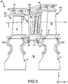
- FIG. 2 schematically shows, by example, a portion of an engine section 68, which is illustrated as a turbine section 28 of gas turbine engine 20.
- Engine section 68 may include a circumferential array of blades 70 coupled about a circumference of a generally circular disk 74.
- Disk 74 may be disposed radially inward of core flowpath C and centered on the rotation axis of the gas turbine engine.
- Disk 74 with blades 70 may be configured to rotate about engine central longitudinal axis A-A'.
- Each blade 70 may include an airfoil body 76 with a platform disposed at an inner diameter end wall 72 of the blade 70.
- a disk cavity 80 may be defined between a forward disk and an aft disk. Upstream (forward) and downstream (aft) of blades 70 are circumferential arrays of vanes 90 configured to guide core flowpath C through the engine section 68.
- Each vane 90 may include an airfoil body 96 with an inner diameter platform 94 disposed at an inner diameter end wall 92 of vane 90 and with an outer diameter platform 98 disposed at an outer diameter end wall 102 of vane 90.
- Outer diameter platform 98 may be coupled to engine case structure 36.
- Inner diameter platform 94 and/or outer diameter platform 98 may be coupled to or integral with vane 90.
- Airfoils 100 may be internally cooled engine components. Airfoils 100 may thus define internal cooling passages having serpentine geometry.
- Vane 90 may comprise an array of internal cooling cavities including a direct-fed through cavity 124, a platform-fed through cavity 126 separated by the platform-fed serpentine cavity 128 by divider 130, and a trailing edge cavity 134.
- platform cavity 125 may be in fluid communication with platform-fed through cavity 126 and platform-fed serpentine cavity 128.
- Platform-fed flow 127 may cool the platform surrounding platform cavity 125 and flow into platform-fed through cavity 126 and platform-fed serpentine cavity 128 defined in airfoil 100.
- the relative percentages flowing into platform-fed through cavity 126 and platform-fed serpentine cavity 128 may be determined by divider 130 between the two cavities.
- Divider 130 may be positioned to meter the platform flow into the platform-fed flow cavities based on the relative cross-sectional area of the platform-fed through cavity 126 and platform-fed serpentine cavity 128.
- Divider 130 may thus be a wall formed between platform-fed through cavity 126 and platform-fed serpentine cavity 128.
- a platform-fed serpentine flow 133 may flow into platform-fed serpentine cavity 128 towards trailing edge cavity 134.
- Platform-fed serpentine flow 133 may exit from trailing edge cavity 134 as exit flow 136 into core flow path C (of FIG. 1 ).
- direct-fed through flow 122 from a direct coolant source may flow into direct-fed through cavity 124 towards outlet 139.
- a platform-fed through flow 132 may flow into the platform-fed through cavity 126 towards outlet 139.
- Platform-fed through flow 132 and direct-fed through flow 122 may meet and mix at outlet 139 and exit vane 90 as outgoing through flow 138.
- Outgoing through flow 138 may be directed to an adjacent blade 70 (of FIG. 2 ) to cool the blade.
- components cooled by the mixed flow of the present disclosure may allow the flexibility to reduce or increase through flow exit temperature, while the coolant temperature to the serpentine would respond in an opposite manner.
- the through flow may absorb additional heat load in response to the platform-fed flow temperature elevating to relatively high temperatures.
- the platform-fed flow may absorb additional heat load in response to the through flow temperature elevating to relatively high temperatures.
- cooling system 120 in airfoils may be made using an additive manufacturing technique such as direct metal laser sintering, selective laser sintering, selective laser melting, electron-beam melting, or electron-beam freeform fabrication. Casting may also be used to form cooling cavities of airfoil 100.
- a core may be formed.
- the core of the component wall may have features of the cooling cavities.
- cooling cavities may be formed in a core as positive material.
- the core may then be placed in a mold, and the material to form the internally cooled component may be deposited in the mold.
- the core may later be removed from the internally cooled component, leaving a cavity with the desired geometry.
- Airfoil 100 (as well as other internally cooled components) may be made from an austenitic nickel-chromium-based alloy or other materials capable of withstanding exhaust temperatures.
- references to “one embodiment”, “an embodiment”, “an example embodiment”, etc. indicate that the embodiment described may include a particular feature, structure, or characteristic, but every embodiment may not necessarily include the particular feature, structure, or characteristic. Moreover, such phrases are not necessarily referring to the same embodiment. Further, when a particular feature, structure, or characteristic is described in connection with an embodiment, it is submitted that it is within the knowledge of one skilled in the art to affect such feature, structure, or characteristic in connection with other embodiments whether or not explicitly described. After reading the description, it will be apparent to one skilled in the relevant art(s) how to implement the disclosure in alternative embodiment
Applications Claiming Priority (1)
| Application Number | Priority Date | Filing Date | Title |
|---|---|---|---|
| US15/613,686 US10513947B2 (en) | 2017-06-05 | 2017-06-05 | Adjustable flow split platform cooling for gas turbine engine |
Publications (2)
| Publication Number | Publication Date |
|---|---|
| EP3412868A1 true EP3412868A1 (fr) | 2018-12-12 |
| EP3412868B1 EP3412868B1 (fr) | 2020-01-29 |
Family
ID=61832311
Family Applications (1)
| Application Number | Title | Priority Date | Filing Date |
|---|---|---|---|
| EP18164398.2A Active EP3412868B1 (fr) | 2017-06-05 | 2018-03-27 | Aube statorique avec refroidissement fendu à débit réglable de plate-forme pour turbine à gaz |
Country Status (2)
| Country | Link |
|---|---|
| US (1) | US10513947B2 (fr) |
| EP (1) | EP3412868B1 (fr) |
Families Citing this family (2)
| Publication number | Priority date | Publication date | Assignee | Title |
|---|---|---|---|---|
| US10508548B2 (en) * | 2017-04-07 | 2019-12-17 | General Electric Company | Turbine engine with a platform cooling circuit |
| US11572796B2 (en) * | 2020-04-17 | 2023-02-07 | Raytheon Technologies Corporation | Multi-material vane for a gas turbine engine |
Citations (6)
| Publication number | Priority date | Publication date | Assignee | Title |
|---|---|---|---|---|
| US5320483A (en) * | 1992-12-30 | 1994-06-14 | General Electric Company | Steam and air cooling for stator stage of a turbine |
| EP0911489A1 (fr) * | 1997-05-01 | 1999-04-28 | Mitsubishi Heavy Industries, Ltd. | Pale stationnaire servant au refroidissement d'une turbine a gaz |
| EP1136652A1 (fr) * | 2000-03-23 | 2001-09-26 | General Electric Company | Segment d'ailette de guidage à turbine avec circulation interne de refroidissement |
| US20030002979A1 (en) * | 2001-06-28 | 2003-01-02 | Koschier Angelo Von | Hybrid turbine nozzle |
| EP2626519A1 (fr) * | 2012-02-09 | 2013-08-14 | Siemens Aktiengesellschaft | Ensemble pour turbine, tube de refroidissement par impact et moteur à turbine à vapeur. |
| EP3196415A1 (fr) * | 2016-01-25 | 2017-07-26 | Rolls-Royce Corporation | Aube de turbine refroidie |
Family Cites Families (11)
| Publication number | Priority date | Publication date | Assignee | Title |
|---|---|---|---|---|
| US5356265A (en) | 1992-08-25 | 1994-10-18 | General Electric Company | Chordally bifurcated turbine blade |
| US5413458A (en) | 1994-03-29 | 1995-05-09 | United Technologies Corporation | Turbine vane with a platform cavity having a double feed for cooling fluid |
| US5645397A (en) * | 1995-10-10 | 1997-07-08 | United Technologies Corporation | Turbine vane assembly with multiple passage cooled vanes |
| GB0005898D0 (en) | 2000-03-10 | 2000-05-03 | Templeton Stephen J | Method and apparatus for introducing a moving liquid into a larger mass of moving liquid |
| US6929445B2 (en) | 2003-10-22 | 2005-08-16 | General Electric Company | Split flow turbine nozzle |
| US7458778B1 (en) | 2006-06-14 | 2008-12-02 | Florida Turbine Technologies, Inc. | Turbine airfoil with a bifurcated counter flow serpentine path |
| US8197184B2 (en) | 2006-10-18 | 2012-06-12 | United Technologies Corporation | Vane with enhanced heat transfer |
| US8591189B2 (en) | 2006-11-20 | 2013-11-26 | General Electric Company | Bifeed serpentine cooled blade |
| US9957813B2 (en) | 2013-02-19 | 2018-05-01 | United Technologies Corporation | Gas turbine engine airfoil platform cooling passage and core |
| US10150187B2 (en) * | 2013-07-26 | 2018-12-11 | Siemens Energy, Inc. | Trailing edge cooling arrangement for an airfoil of a gas turbine engine |
| WO2017003455A1 (fr) | 2015-06-30 | 2017-01-05 | Siemens Aktiengesellschaft | Circuit de refroidissement d'aube de stator de turbine ayant une séparation de flux d'écoulement |
-
2017
- 2017-06-05 US US15/613,686 patent/US10513947B2/en active Active
-
2018
- 2018-03-27 EP EP18164398.2A patent/EP3412868B1/fr active Active
Patent Citations (6)
| Publication number | Priority date | Publication date | Assignee | Title |
|---|---|---|---|---|
| US5320483A (en) * | 1992-12-30 | 1994-06-14 | General Electric Company | Steam and air cooling for stator stage of a turbine |
| EP0911489A1 (fr) * | 1997-05-01 | 1999-04-28 | Mitsubishi Heavy Industries, Ltd. | Pale stationnaire servant au refroidissement d'une turbine a gaz |
| EP1136652A1 (fr) * | 2000-03-23 | 2001-09-26 | General Electric Company | Segment d'ailette de guidage à turbine avec circulation interne de refroidissement |
| US20030002979A1 (en) * | 2001-06-28 | 2003-01-02 | Koschier Angelo Von | Hybrid turbine nozzle |
| EP2626519A1 (fr) * | 2012-02-09 | 2013-08-14 | Siemens Aktiengesellschaft | Ensemble pour turbine, tube de refroidissement par impact et moteur à turbine à vapeur. |
| EP3196415A1 (fr) * | 2016-01-25 | 2017-07-26 | Rolls-Royce Corporation | Aube de turbine refroidie |
Also Published As
| Publication number | Publication date |
|---|---|
| EP3412868B1 (fr) | 2020-01-29 |
| US20180347397A1 (en) | 2018-12-06 |
| US10513947B2 (en) | 2019-12-24 |
Similar Documents
| Publication | Publication Date | Title |
|---|---|---|
| EP3480432B1 (fr) | Treillis structurel modifié pour surfaces portantes | |
| EP3020923B1 (fr) | Aube de turbine refroidie | |
| EP2900961B1 (fr) | Circuit de refroidissement d'aube de moteur à turbine à gaz | |
| EP3396112B1 (fr) | Canaux de refroidissement de plate-forme portante | |
| US10934845B2 (en) | Dual cooling airflow to blades | |
| US9963972B2 (en) | Mixing plenum for spoked rotors | |
| EP3412868B1 (fr) | Aube statorique avec refroidissement fendu à débit réglable de plate-forme pour turbine à gaz | |
| US20230116394A1 (en) | Tandem blade rotor disk | |
| US9957820B2 (en) | Heat shield for a vane assembly of a gas turbine engine | |
| EP3477058B1 (fr) | Circuit de refroidissement de profil aérodynamique | |
| EP3101228B1 (fr) | Déflecteur de division d'écoulement | |
| US9835032B2 (en) | Disk lug cooling flow trenches | |
| US10822959B2 (en) | Blade tip cooling | |
| EP3293361B1 (fr) | Moteur à turbine à gaz et procédé de fabrication associé |
Legal Events
| Date | Code | Title | Description |
|---|---|---|---|
| PUAI | Public reference made under article 153(3) epc to a published international application that has entered the european phase |
Free format text: ORIGINAL CODE: 0009012 |
|
| STAA | Information on the status of an ep patent application or granted ep patent |
Free format text: STATUS: THE APPLICATION HAS BEEN PUBLISHED |
|
| AK | Designated contracting states |
Kind code of ref document: A1 Designated state(s): AL AT BE BG CH CY CZ DE DK EE ES FI FR GB GR HR HU IE IS IT LI LT LU LV MC MK MT NL NO PL PT RO RS SE SI SK SM TR |
|
| AX | Request for extension of the european patent |
Extension state: BA ME |
|
| STAA | Information on the status of an ep patent application or granted ep patent |
Free format text: STATUS: REQUEST FOR EXAMINATION WAS MADE |
|
| 17P | Request for examination filed |
Effective date: 20190612 |
|
| RBV | Designated contracting states (corrected) |
Designated state(s): AL AT BE BG CH CY CZ DE DK EE ES FI FR GB GR HR HU IE IS IT LI LT LU LV MC MK MT NL NO PL PT RO RS SE SI SK SM TR |
|
| GRAP | Despatch of communication of intention to grant a patent |
Free format text: ORIGINAL CODE: EPIDOSNIGR1 |
|
| STAA | Information on the status of an ep patent application or granted ep patent |
Free format text: STATUS: GRANT OF PATENT IS INTENDED |
|
| INTG | Intention to grant announced |
Effective date: 20190807 |
|
| GRAS | Grant fee paid |
Free format text: ORIGINAL CODE: EPIDOSNIGR3 |
|
| GRAA | (expected) grant |
Free format text: ORIGINAL CODE: 0009210 |
|
| STAA | Information on the status of an ep patent application or granted ep patent |
Free format text: STATUS: THE PATENT HAS BEEN GRANTED |
|
| AK | Designated contracting states |
Kind code of ref document: B1 Designated state(s): AL AT BE BG CH CY CZ DE DK EE ES FI FR GB GR HR HU IE IS IT LI LT LU LV MC MK MT NL NO PL PT RO RS SE SI SK SM TR |
|
| REG | Reference to a national code |
Ref country code: GB Ref legal event code: FG4D |
|
| REG | Reference to a national code |
Ref country code: CH Ref legal event code: EP |
|
| REG | Reference to a national code |
Ref country code: AT Ref legal event code: REF Ref document number: 1228633 Country of ref document: AT Kind code of ref document: T Effective date: 20200215 |
|
| REG | Reference to a national code |
Ref country code: IE Ref legal event code: FG4D |
|
| REG | Reference to a national code |
Ref country code: DE Ref legal event code: R096 Ref document number: 602018002177 Country of ref document: DE |
|
| REG | Reference to a national code |
Ref country code: NL Ref legal event code: MP Effective date: 20200129 |
|
| PG25 | Lapsed in a contracting state [announced via postgrant information from national office to epo] |
Ref country code: PT Free format text: LAPSE BECAUSE OF FAILURE TO SUBMIT A TRANSLATION OF THE DESCRIPTION OR TO PAY THE FEE WITHIN THE PRESCRIBED TIME-LIMIT Effective date: 20200621 Ref country code: NO Free format text: LAPSE BECAUSE OF FAILURE TO SUBMIT A TRANSLATION OF THE DESCRIPTION OR TO PAY THE FEE WITHIN THE PRESCRIBED TIME-LIMIT Effective date: 20200429 Ref country code: RS Free format text: LAPSE BECAUSE OF FAILURE TO SUBMIT A TRANSLATION OF THE DESCRIPTION OR TO PAY THE FEE WITHIN THE PRESCRIBED TIME-LIMIT Effective date: 20200129 Ref country code: FI Free format text: LAPSE BECAUSE OF FAILURE TO SUBMIT A TRANSLATION OF THE DESCRIPTION OR TO PAY THE FEE WITHIN THE PRESCRIBED TIME-LIMIT Effective date: 20200129 |
|
| REG | Reference to a national code |
Ref country code: LT Ref legal event code: MG4D |
|
| PG25 | Lapsed in a contracting state [announced via postgrant information from national office to epo] |
Ref country code: GR Free format text: LAPSE BECAUSE OF FAILURE TO SUBMIT A TRANSLATION OF THE DESCRIPTION OR TO PAY THE FEE WITHIN THE PRESCRIBED TIME-LIMIT Effective date: 20200430 Ref country code: HR Free format text: LAPSE BECAUSE OF FAILURE TO SUBMIT A TRANSLATION OF THE DESCRIPTION OR TO PAY THE FEE WITHIN THE PRESCRIBED TIME-LIMIT Effective date: 20200129 Ref country code: LV Free format text: LAPSE BECAUSE OF FAILURE TO SUBMIT A TRANSLATION OF THE DESCRIPTION OR TO PAY THE FEE WITHIN THE PRESCRIBED TIME-LIMIT Effective date: 20200129 Ref country code: BG Free format text: LAPSE BECAUSE OF FAILURE TO SUBMIT A TRANSLATION OF THE DESCRIPTION OR TO PAY THE FEE WITHIN THE PRESCRIBED TIME-LIMIT Effective date: 20200429 Ref country code: SE Free format text: LAPSE BECAUSE OF FAILURE TO SUBMIT A TRANSLATION OF THE DESCRIPTION OR TO PAY THE FEE WITHIN THE PRESCRIBED TIME-LIMIT Effective date: 20200129 Ref country code: IS Free format text: LAPSE BECAUSE OF FAILURE TO SUBMIT A TRANSLATION OF THE DESCRIPTION OR TO PAY THE FEE WITHIN THE PRESCRIBED TIME-LIMIT Effective date: 20200529 |
|
| PG25 | Lapsed in a contracting state [announced via postgrant information from national office to epo] |
Ref country code: NL Free format text: LAPSE BECAUSE OF FAILURE TO SUBMIT A TRANSLATION OF THE DESCRIPTION OR TO PAY THE FEE WITHIN THE PRESCRIBED TIME-LIMIT Effective date: 20200129 |
|
| PG25 | Lapsed in a contracting state [announced via postgrant information from national office to epo] |
Ref country code: DK Free format text: LAPSE BECAUSE OF FAILURE TO SUBMIT A TRANSLATION OF THE DESCRIPTION OR TO PAY THE FEE WITHIN THE PRESCRIBED TIME-LIMIT Effective date: 20200129 Ref country code: ES Free format text: LAPSE BECAUSE OF FAILURE TO SUBMIT A TRANSLATION OF THE DESCRIPTION OR TO PAY THE FEE WITHIN THE PRESCRIBED TIME-LIMIT Effective date: 20200129 Ref country code: LT Free format text: LAPSE BECAUSE OF FAILURE TO SUBMIT A TRANSLATION OF THE DESCRIPTION OR TO PAY THE FEE WITHIN THE PRESCRIBED TIME-LIMIT Effective date: 20200129 Ref country code: EE Free format text: LAPSE BECAUSE OF FAILURE TO SUBMIT A TRANSLATION OF THE DESCRIPTION OR TO PAY THE FEE WITHIN THE PRESCRIBED TIME-LIMIT Effective date: 20200129 Ref country code: SM Free format text: LAPSE BECAUSE OF FAILURE TO SUBMIT A TRANSLATION OF THE DESCRIPTION OR TO PAY THE FEE WITHIN THE PRESCRIBED TIME-LIMIT Effective date: 20200129 Ref country code: CZ Free format text: LAPSE BECAUSE OF FAILURE TO SUBMIT A TRANSLATION OF THE DESCRIPTION OR TO PAY THE FEE WITHIN THE PRESCRIBED TIME-LIMIT Effective date: 20200129 Ref country code: RO Free format text: LAPSE BECAUSE OF FAILURE TO SUBMIT A TRANSLATION OF THE DESCRIPTION OR TO PAY THE FEE WITHIN THE PRESCRIBED TIME-LIMIT Effective date: 20200129 Ref country code: MC Free format text: LAPSE BECAUSE OF FAILURE TO SUBMIT A TRANSLATION OF THE DESCRIPTION OR TO PAY THE FEE WITHIN THE PRESCRIBED TIME-LIMIT Effective date: 20200129 Ref country code: SK Free format text: LAPSE BECAUSE OF FAILURE TO SUBMIT A TRANSLATION OF THE DESCRIPTION OR TO PAY THE FEE WITHIN THE PRESCRIBED TIME-LIMIT Effective date: 20200129 |
|
| REG | Reference to a national code |
Ref country code: DE Ref legal event code: R097 Ref document number: 602018002177 Country of ref document: DE |
|
| REG | Reference to a national code |
Ref country code: AT Ref legal event code: MK05 Ref document number: 1228633 Country of ref document: AT Kind code of ref document: T Effective date: 20200129 |
|
| PLBE | No opposition filed within time limit |
Free format text: ORIGINAL CODE: 0009261 |
|
| STAA | Information on the status of an ep patent application or granted ep patent |
Free format text: STATUS: NO OPPOSITION FILED WITHIN TIME LIMIT |
|
| REG | Reference to a national code |
Ref country code: BE Ref legal event code: MM Effective date: 20200331 |
|
| PG25 | Lapsed in a contracting state [announced via postgrant information from national office to epo] |
Ref country code: LU Free format text: LAPSE BECAUSE OF NON-PAYMENT OF DUE FEES Effective date: 20200327 |
|
| 26N | No opposition filed |
Effective date: 20201030 |
|
| PG25 | Lapsed in a contracting state [announced via postgrant information from national office to epo] |
Ref country code: IT Free format text: LAPSE BECAUSE OF FAILURE TO SUBMIT A TRANSLATION OF THE DESCRIPTION OR TO PAY THE FEE WITHIN THE PRESCRIBED TIME-LIMIT Effective date: 20200129 Ref country code: IE Free format text: LAPSE BECAUSE OF NON-PAYMENT OF DUE FEES Effective date: 20200327 Ref country code: AT Free format text: LAPSE BECAUSE OF FAILURE TO SUBMIT A TRANSLATION OF THE DESCRIPTION OR TO PAY THE FEE WITHIN THE PRESCRIBED TIME-LIMIT Effective date: 20200129 |
|
| PG25 | Lapsed in a contracting state [announced via postgrant information from national office to epo] |
Ref country code: BE Free format text: LAPSE BECAUSE OF NON-PAYMENT OF DUE FEES Effective date: 20200331 Ref country code: PL Free format text: LAPSE BECAUSE OF FAILURE TO SUBMIT A TRANSLATION OF THE DESCRIPTION OR TO PAY THE FEE WITHIN THE PRESCRIBED TIME-LIMIT Effective date: 20200129 Ref country code: SI Free format text: LAPSE BECAUSE OF FAILURE TO SUBMIT A TRANSLATION OF THE DESCRIPTION OR TO PAY THE FEE WITHIN THE PRESCRIBED TIME-LIMIT Effective date: 20200129 |
|
| REG | Reference to a national code |
Ref country code: CH Ref legal event code: PL |
|
| PG25 | Lapsed in a contracting state [announced via postgrant information from national office to epo] |
Ref country code: CH Free format text: LAPSE BECAUSE OF NON-PAYMENT OF DUE FEES Effective date: 20210331 Ref country code: LI Free format text: LAPSE BECAUSE OF NON-PAYMENT OF DUE FEES Effective date: 20210331 |
|
| PG25 | Lapsed in a contracting state [announced via postgrant information from national office to epo] |
Ref country code: TR Free format text: LAPSE BECAUSE OF FAILURE TO SUBMIT A TRANSLATION OF THE DESCRIPTION OR TO PAY THE FEE WITHIN THE PRESCRIBED TIME-LIMIT Effective date: 20200129 Ref country code: MT Free format text: LAPSE BECAUSE OF FAILURE TO SUBMIT A TRANSLATION OF THE DESCRIPTION OR TO PAY THE FEE WITHIN THE PRESCRIBED TIME-LIMIT Effective date: 20200129 Ref country code: CY Free format text: LAPSE BECAUSE OF FAILURE TO SUBMIT A TRANSLATION OF THE DESCRIPTION OR TO PAY THE FEE WITHIN THE PRESCRIBED TIME-LIMIT Effective date: 20200129 |
|
| PG25 | Lapsed in a contracting state [announced via postgrant information from national office to epo] |
Ref country code: MK Free format text: LAPSE BECAUSE OF FAILURE TO SUBMIT A TRANSLATION OF THE DESCRIPTION OR TO PAY THE FEE WITHIN THE PRESCRIBED TIME-LIMIT Effective date: 20200129 Ref country code: AL Free format text: LAPSE BECAUSE OF FAILURE TO SUBMIT A TRANSLATION OF THE DESCRIPTION OR TO PAY THE FEE WITHIN THE PRESCRIBED TIME-LIMIT Effective date: 20200129 |
|
| REG | Reference to a national code |
Ref country code: DE Ref legal event code: R081 Ref document number: 602018002177 Country of ref document: DE Owner name: RAYTHEON TECHNOLOGIES CORPORATION (N.D.GES.D.S, US Free format text: FORMER OWNER: UNITED TECHNOLOGIES CORPORATION, FARMINGTON, CONN., US |
|
| PGFP | Annual fee paid to national office [announced via postgrant information from national office to epo] |
Ref country code: FR Payment date: 20230222 Year of fee payment: 6 |
|
| P01 | Opt-out of the competence of the unified patent court (upc) registered |
Effective date: 20230521 |
|
| PGFP | Annual fee paid to national office [announced via postgrant information from national office to epo] |
Ref country code: DE Payment date: 20240220 Year of fee payment: 7 Ref country code: GB Payment date: 20240220 Year of fee payment: 7 |