EP3412807B1 - Rotor cleaning device of an open-end type spinning apparatus, an auxiliary carriage of an open-end type spinning apparatus and corresponding open-end type spinning apparatus - Google Patents
Rotor cleaning device of an open-end type spinning apparatus, an auxiliary carriage of an open-end type spinning apparatus and corresponding open-end type spinning apparatus Download PDFInfo
- Publication number
- EP3412807B1 EP3412807B1 EP18171904.8A EP18171904A EP3412807B1 EP 3412807 B1 EP3412807 B1 EP 3412807B1 EP 18171904 A EP18171904 A EP 18171904A EP 3412807 B1 EP3412807 B1 EP 3412807B1
- Authority
- EP
- European Patent Office
- Prior art keywords
- open
- rotor
- spinning apparatus
- type spinning
- cleaning device
- Prior art date
- Legal status (The legal status is an assumption and is not a legal conclusion. Google has not performed a legal analysis and makes no representation as to the accuracy of the status listed.)
- Active
Links
Images



Classifications
-
- D—TEXTILES; PAPER
- D01—NATURAL OR MAN-MADE THREADS OR FIBRES; SPINNING
- D01H—SPINNING OR TWISTING
- D01H4/00—Open-end spinning machines or arrangements for imparting twist to independently moving fibres separated from slivers; Piecing arrangements therefor; Covering endless core threads with fibres by open-end spinning techniques
- D01H4/04—Open-end spinning machines or arrangements for imparting twist to independently moving fibres separated from slivers; Piecing arrangements therefor; Covering endless core threads with fibres by open-end spinning techniques imparting twist by contact of fibres with a running surface
- D01H4/22—Cleaning of running surfaces
- D01H4/24—Cleaning of running surfaces in rotor spinning
Definitions
- the present invention relates to a rotor cleaning device of an open-end type spinning apparatus, an auxiliary carriage of an open-end type spinning apparatus and relative open-end type spinning apparatus.
- the cleaning of the rotor of an open-end spinning apparatus is carried out in two typical circumstances, that is, when the quality of the yarn falls below a certain predetermined level, or whenever there is a break in the yarn in production.
- the spinning unit is stopped and, before starting again, the spinning condition is also restored by cleaning the rotor.
- This cleaning is performed by a device called rotor cleaning device, physically dislocated on the piecing carriage with which the spinning apparatus is provided.
- rotor cleaning device Some solutions of the prior art provide for the use of a scraper which is first inserted and then rotated in contact with the surface of the inner wall of the rotor to be cleaned.
- this solution involves the drawback of stressing the bearings which rotatably support the rotor in an asymmetrical manner, with considerable forces.
- the rotor is a component that must rotate at very high rotational speeds of the order of several tens of thousands of revolutions per minute: for this reason, such asymmetric stresses can cause damage to the bearings or in any case can significantly reduce their useful life, requiring more frequent maintenance and/or replacement.
- US4155217A discloses a rotor cleaning device with a cleaning head comprising a brush supported on a brush shaft.
- reference numeral 4 globally indicates an overall schematic view of an open-end type spinning apparatus according to the present invention.
- the spinning apparatus 4 comprises at least one spinning head 8 having a spinning unit 12 and a reel winding unit 16, wherein the reel winding unit 16 wraps on a tube 20 a reel of yarn obtained from the underlying spinning unit 12.
- the spinning apparatus 4 also comprises a tube-holder basket 24 which houses a plurality of tubes 20 on which to wind the yarn.
- the spinning unit 12 comprises an open-end rotor 28 which produces yarn, starting from a roving, in a known manner.
- the spinning apparatus 4 also comprises a doffing carriage 22 which can be positioned at the spinning unit 12 and is provided with a plurality of devices for carrying out operations on the spinning head; for example, such devices may comprise pick-up and transport devices 34 of a tube 20 from the tube-holder basket 24 to a pair of tailstocks 36 of the reel wrapping unit 16, a lifting device for removing the formed reel from the tailstocks and so on.
- a doffing carriage 22 which can be positioned at the spinning unit 12 and is provided with a plurality of devices for carrying out operations on the spinning head; for example, such devices may comprise pick-up and transport devices 34 of a tube 20 from the tube-holder basket 24 to a pair of tailstocks 36 of the reel wrapping unit 16, a lifting device for removing the formed reel from the tailstocks and so on.
- the spinning apparatus further comprises a piecing carriage or auxiliary carriage 23 which comprises, for example, a yarn re-attaching device (not shown).
- the open-end rotor 28 is cleaned, preferably after it has stopped.
- this cleaning is carried out by means of a rotor cleaning device 40 of an open-end spinning apparatus mounted on said piecing carriage 23.
- the rotor cleaning device 40 comprises a cleaning head 44 for cleaning the open-end rotor 28.
- the open-end rotor 28 in a known manner, comprises a shank 29 for its dragging into rotation and a rotor body 30 having axial symmetrical conformation about an axis of symmetry S-S, coaxial with said shank, and delimiting a cavity 31.
- the axis of symmetry S-S coincides with the axis of rotation of the open-end rotor 28, in a known manner.
- Said cavity 31 comprises a throat 32 and an inner lateral wall 33 which are axial-symmetrical with respect to said axis of symmetry S-S.
- Said cleaning head 44 comprises a scraper 48 and/or a brush 52.
- the scraper 48 is mounted in front of the brush 52 with respect to a frontal approaching direction of the rotor cleaning device 40 to the open-end rotor 28.
- the scraper 48 has a tapered conformation so as to be counter-shaped with respect to the groove 32 of said open-end rotor 28. In this way, the cleaning capacity of the scraper 48 is improved near a critical point of the open-end rotor 28, such as the groove 32.
- the brush 52 has a tapered conformation along an axial extension, parallel to said axis of symmetry S-S, away from the scraper 48.
- the brush 52 has brushes which are counter-shaped with respect to the inner lateral wall 33 of the rotor body 30. This improves the cleaning capacity of the brush 52 on the inner lateral wall 33.
- the scraper 48 and the brush 52 have such a size that they can be inserted, without interference, at least partially inside the cavity 31 so as to be able to reach and clean the throat 32 and the inner lateral wall 33 of the rotor body 30, respectively.
- the scraper 48 and/or the brush 52 are made of a polymeric material having a hardness lower than the hardness of the corresponding open-end rotor 28 to be cleaned. In this way, it is possible to avoid scratches and damages on the throat 32 and on the inner lateral wall 33 of the open-end rotor 28.
- the rotor cleaning device 40 comprises a drive system 56, comprising a first motor 60 for the rotation of the cleaning head 44 and a kinematic mechanism 64 mechanically connecting the first motor 60 to the cleaning head 44.
- the kinematic mechanism 64 comprises a mechanical connection between the first motor 60 and a support 68 of the cleaning head 44 with respect to a main rotation axis X-X of the cleaning head itself.
- the first motor 60 and the support 68 of the cleaning head 44 rotate together coaxially with the main rotation axis.
- the first motor 60 is preferably, but not exclusively, a step-by-step electric motor.
- the scraper 48 and/or the brush 52 of the cleaning head 44 are rotatably assembled around a secondary rotation axis Y-Y on a pin 72 eccentric to said main axis of rotation X-X and supported by said support 68.
- the pin 72 is in turn engaged with the first motor 60 by means of a pair of gears 69.
- the secondary rotation axis Y-Y is parallel to the main axis of rotation X-X, and is offset with respect thereto by an eccentricity 76.
- said eccentricity 76 is between 7% and 33% of the maximum diameter of the rotor to be cleaned.
- the scraper 48 and the brush 52 are rotatably integral with the same eccentric pin 72.
- a freewheel 70 is inserted, configured to allow rotation of the entire support 68 in said active direction.
- first motor 60 and the support 68 rotate together in an active direction of rotation, which can be either clockwise or counterclockwise.
- the scraper 48 and/or the brush 52 rotate inside the open-end rotor 28 until it comes into contact with the throat 32 and/or with the inner lateral wall 33 of the rotor body 30. In this step, the support 68 does not rotate ( figures 8-9 ).
- the driving torque supplied by the first motor 60 rotates the support 68 which begins to rotate according to the active direction of rotation. In this rotation motion, it drags the scraper 48 and/or the brush 52 with it, so as to effectively clean the throat 32 and/or the inner lateral wall 33 of the open end rotor 28.
- the kinematic mechanism 64 comprises a gear train having a case 80 that acts as a support 68 of the cleaning head 44, and a satellite 84, associated with the case 80, which serves as eccentric pin 72.
- the rotor cleaning device 40 further comprises a movement system 88 to bring the cleaning head 44 near the open-end rotor 28 to be cleaned.
- the movement system 88 comprises a base 90 and at least one pair of connecting rods 92, 94 which guide according to a tilting movement a containment body 96 which supports the cleaning head 44 and the drive system 56.
- the base 90, the containment body 96 and the pair of connecting rods 92, 94 form an articulated quadrilateral.
- connecting rods 92, 94 allows the containment body 96 to be moved in a controlled manner in space, i.e. parallel to base 90. In this way, it is possible to correctly align the cleaning head 44 with the open-end rotor 28 so as to align the symmetrical axis of the open-end rotor 28 with the main axis of rotation X-X, which must be parallel and coaxial with each other.
- the movement system 88 comprises a second motor 100 for the rotation and controlled positioning of the cleaning head 44, from a retracted or rest configuration ( figure 3 ) to an extracted or working configuration ( figure 4 ).
- the rotor cleaning device 40 comprises a second cleaning head 104 of a funnel of an open-end spinning apparatus 4.
- the second cleaning head 104 of a funnel comprises a front brush 110 keyed on a turbine 112, for example pneumatically driven ( figure 12 ).
- a turbine 112 for example pneumatically driven ( figure 12 ).
- the second cleaning head 104 of a funnel is oriented along a third axis W-W substantially perpendicular to said main axis of rotation X-X.
- the open-end rotor 28 is cleaned, preferably after it has stopped.
- the piecing carriage 23 of the open-end spinning apparatus 4 approaches the open-end rotor 28 to be cleaned and the movement system 88 carries the cleaning head 44 from the retracted or rest configuration to the extracted or working configuration, so as to position the cleaning head 44 inside the cavity 31 of the open-end rotor 48 so as to align the main rotation axis X-X with the axis of symmetry S-S of the rotor body 30.
- the cleaning head moves inside the open end rotor 28 so that the scraper 48 and/or the brush 52 are correctly oriented, i.e. so that the scraper 48 and/or the brush 52 can frontally enter into the open-end rotor 28, without interfering with the rotor body 30 ( figures 8-9 ).
- the drive system 56 by means of the first motor 60, rotates the scraper 48 and/or the brush 52 in an eccentric manner with respect to the main axis of rotation X-X of the first motor 60 which, as seen, is in turn aligned to the symmetry axis S-S of the open-end rotor 28 to be cleaned.
- the scrapers 48 and the brush 52 are made of polymers (POM type) which, with their hardness, allow an adequate abrasive action of the impurities without thereby damaging the throat 32 and the inner lateral wall 33 of the open-end rotor 28.
- the rotation of the first motor 60 is reversed; due to the freewheel mechanism 70 during the rotation of the first motor 60, the support 68 cannot rotate according to the passive direction; in this way, the rotation transmitted to the scraper 48 and/or brush 52 returns the latter to the initial position ( figures 8-9 ) so as to allow subsequent removal of the cleaning head 44 from the open-end rotor 28, without colliding with the mouth of the rotor.
- the rotor cleaning device of an open-end spinning apparatus and the relative open-end spinning apparatus allow overcoming the drawbacks of the prior art.
- the solution of the present invention allows effectively cleaning the open-end rotor of an open-end spinning apparatus without excessively stressing the open-end rotor in a radial direction, thus preserving the relative bearings of the rotor itself.
- the torque transmitted by the first motor is used to rotate the scraper/brush; when the latter is impinged on the rotor throat, said torque is transferred to the kinematic mechanism to allow rotation of the entire cleaning head. This ensures that the rotor support bearings are not damaged.
- the rotor cleaning device is simple and inexpensive since the scraping elements are not extensible in the radial direction (such as those of the prior art) but leave the resting position 'below the contour' by tilting around the axis on which they are pivoted.
- both the scraper and the brush abrade impurities without damaging the internal surfaces of the rotor: in fact, both the scraper and the brush are made of less harsh polymeric material than the surfaces to be cleaned that are not scratched or abraded thereby.
- the impurities are then removed by compressed air and aspirated by means of a relative suction system, in a known manner.
- Another strength which characterizes the rotor cleaning device of the present invention is the self-adaptability of the head which cleans the rotor.
- the tilting system that brings the scrapers into working position allows the scrapers to work in the correct position even when cleaning rotors of different diameters.
- the solution of the present invention is particularly versatile and adaptable to rotors of different sizes.
Landscapes
- Engineering & Computer Science (AREA)
- Mechanical Engineering (AREA)
- Textile Engineering (AREA)
- Spinning Or Twisting Of Yarns (AREA)
Description
- The present invention relates to a rotor cleaning device of an open-end type spinning apparatus, an auxiliary carriage of an open-end type spinning apparatus and relative open-end type spinning apparatus.
- As is known, the cleaning of the rotor of an open-end spinning apparatus is carried out in two typical circumstances, that is, when the quality of the yarn falls below a certain predetermined level, or whenever there is a break in the yarn in production.
- In both the aforementioned cases, the spinning unit is stopped and, before starting again, the spinning condition is also restored by cleaning the rotor.
- This cleaning is performed by a device called rotor cleaning device, physically dislocated on the piecing carriage with which the spinning apparatus is provided. Some solutions of the prior art provide for the use of a scraper which is first inserted and then rotated in contact with the surface of the inner wall of the rotor to be cleaned. However, this solution involves the drawback of stressing the bearings which rotatably support the rotor in an asymmetrical manner, with considerable forces. The rotor is a component that must rotate at very high rotational speeds of the order of several tens of thousands of revolutions per minute: for this reason, such asymmetric stresses can cause damage to the bearings or in any case can significantly reduce their useful life, requiring more frequent maintenance and/or replacement.
- There are also devices that provide for the insertion of a scraper that moves only radially and then the rotor is rotated by means of a motor and a friction wheel.
- Solutions are also known in the art which provide, for example, the use of scraping elements extensible in a radial direction, described for example in
EP1344852 /US6910326 , so that the scraper enters frontally inside the rotor to be cleaned, in the retracted position so as not to interfere with the mouth and the side wall of the rotor to be cleaned and then, once extracted, it can scrape the throat of the rotor, and possibly said side wall to clean it. - Such known cleaning systems provide two diametrically opposed scrapers to compensate for radial stresses by reducing to zero (or almost zero) the forces transferred to the rotor. In this way, the radial contact forces exchanged with the rotor are practically nil. However, this solution is not free from drawbacks since it requires a piston and spring device to be actuated, which pushes the scrapers into the working position and another actuator device (typically an electric motor) to allow rotation of the cleaning head (or alternatively of the rotor itself).
- Therefore, these solutions, although avoiding unbalanced radial loads on the rotor axis, are mechanically complex and therefore expensive.
-
US4155217A discloses a rotor cleaning device with a cleaning head comprising a brush supported on a brush shaft. - Thus the known solutions described above have drawbacks and limitations, essentially due to the fact that they provide for the use of complex and expensive devices to avoid unbalanced radial loads on the rotor.
- Further known solutions, mechanically simpler and cheaper, do not solve the problem of excessive mechanical stress on the rotor for unbalanced radial loads.
- The need to solve the drawbacks and limitations mentioned with reference to the prior art is therefore felt.
- This need is met by a rotor cleaning device of an open-end spinning apparatus according to claim 1, by a piecing carriage of an open-end spinning apparatus according to claim 15 and by an open-end spinning apparatus according to
claim 16. - Further features and advantages of the present invention will appear more clearly from the following description of preferred non-limiting embodiments thereof, in which:
-
figure 1 shows a side view of an open-end type spinning apparatus according to an embodiment of the present invention; -
figure 2 shows a partially sectional perspective view of a portion of the open-end type spinning apparatus infigure 1 ; -
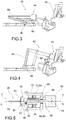
figures 3-4 show side views of a rotor cleaning device of an open-end type spinning apparatus according to the present invention, in a retracted and extracted position, respectively; -
figure 5 shows a side sectional view of a cleaning apparatus according to an embodiment of the present invention; -
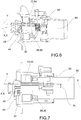
figures 6-7 show two sectional views, respectively perspective and side, of a cleaning apparatus according to the present invention; -
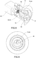
figure 8 shows a perspective sectional view of a rotor cleaning device in a first step of insertion into a rotor to be cleaned; -
figure 9 shows a view of the cleaning device infigure 8 , from the side of arrow IX infigure 8 ; -
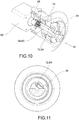
figure 10 shows a perspective sectional view of a rotor cleaning device in a step of cleaning a rotor; -
figure 11 shows a view of the cleaning device infigure 10 , from the side of arrow XI infigure 10 ; -
figures 12 to 13 show partial perspective views of further embodiments of rotor cleaning devices of an open-end type spinning apparatus according to the present invention. - Elements, or parts of elements, in common to the embodiments described below are referred to with the same reference numerals.
- With reference to the above figures,
reference numeral 4 globally indicates an overall schematic view of an open-end type spinning apparatus according to the present invention. - In particular, the
spinning apparatus 4 comprises at least one spinning head 8 having a spinning unit 12 and areel winding unit 16, wherein thereel winding unit 16 wraps on a tube 20 a reel of yarn obtained from the underlying spinning unit 12. - The
spinning apparatus 4 also comprises a tube-holder basket 24 which houses a plurality oftubes 20 on which to wind the yarn. - The spinning unit 12 comprises an open-
end rotor 28 which produces yarn, starting from a roving, in a known manner. - The
spinning apparatus 4 also comprises a doffing carriage 22 which can be positioned at the spinning unit 12 and is provided with a plurality of devices for carrying out operations on the spinning head; for example, such devices may comprise pick-up andtransport devices 34 of atube 20 from the tube-holder basket 24 to a pair oftailstocks 36 of thereel wrapping unit 16, a lifting device for removing the formed reel from the tailstocks and so on. - The spinning apparatus further comprises a piecing carriage or
auxiliary carriage 23 which comprises, for example, a yarn re-attaching device (not shown). - In the event of breakage of the yarn in production or when the yarn quality falls below a certain predetermined level, the open-
end rotor 28 is cleaned, preferably after it has stopped. - In particular, this cleaning is carried out by means of a
rotor cleaning device 40 of an open-end spinning apparatus mounted on saidpiecing carriage 23. - The
rotor cleaning device 40 comprises acleaning head 44 for cleaning the open-end rotor 28. - The open-
end rotor 28, in a known manner, comprises ashank 29 for its dragging into rotation and arotor body 30 having axial symmetrical conformation about an axis of symmetry S-S, coaxial with said shank, and delimiting acavity 31. - The axis of symmetry S-S coincides with the axis of rotation of the open-
end rotor 28, in a known manner. - Said
cavity 31 comprises athroat 32 and an innerlateral wall 33 which are axial-symmetrical with respect to said axis of symmetry S-S. - Said cleaning
head 44 comprises ascraper 48 and/or abrush 52. - The
scraper 48 is mounted in front of thebrush 52 with respect to a frontal approaching direction of therotor cleaning device 40 to the open-end rotor 28. - Preferably, the
scraper 48 has a tapered conformation so as to be counter-shaped with respect to thegroove 32 of said open-end rotor 28. In this way, the cleaning capacity of thescraper 48 is improved near a critical point of the open-end rotor 28, such as thegroove 32. - Preferably, the
brush 52 has a tapered conformation along an axial extension, parallel to said axis of symmetry S-S, away from thescraper 48. - In this way, the
brush 52 has brushes which are counter-shaped with respect to the innerlateral wall 33 of therotor body 30. This improves the cleaning capacity of thebrush 52 on the innerlateral wall 33. - Obviously, the
scraper 48 and thebrush 52 have such a size that they can be inserted, without interference, at least partially inside thecavity 31 so as to be able to reach and clean thethroat 32 and the innerlateral wall 33 of therotor body 30, respectively. - Preferably, the
scraper 48 and/or thebrush 52 are made of a polymeric material having a hardness lower than the hardness of the corresponding open-end rotor 28 to be cleaned. In this way, it is possible to avoid scratches and damages on thethroat 32 and on the innerlateral wall 33 of the open-end rotor 28. - The
rotor cleaning device 40 comprises adrive system 56, comprising afirst motor 60 for the rotation of thecleaning head 44 and akinematic mechanism 64 mechanically connecting thefirst motor 60 to thecleaning head 44. - Advantageously, the
kinematic mechanism 64 comprises a mechanical connection between thefirst motor 60 and a support 68 of thecleaning head 44 with respect to a main rotation axis X-X of the cleaning head itself. - In other words, the
first motor 60 and the support 68 of thecleaning head 44 rotate together coaxially with the main rotation axis. - The
first motor 60 is preferably, but not exclusively, a step-by-step electric motor. - Advantageously, the
scraper 48 and/or thebrush 52 of thecleaning head 44 are rotatably assembled around a secondary rotation axis Y-Y on a pin 72 eccentric to said main axis of rotation X-X and supported by said support 68. The pin 72 is in turn engaged with thefirst motor 60 by means of a pair ofgears 69. - The secondary rotation axis Y-Y is parallel to the main axis of rotation X-X, and is offset with respect thereto by an
eccentricity 76. - Preferably, said
eccentricity 76 is between 7% and 33% of the maximum diameter of the rotor to be cleaned. - The
scraper 48 and thebrush 52 are rotatably integral with the same eccentric pin 72. - Moreover, between the
first motor 60 and the support 68 afreewheel 70 is inserted, configured to allow rotation of the entire support 68 in said active direction. - In particular, in a first step the
first motor 60 and the support 68 rotate together in an active direction of rotation, which can be either clockwise or counterclockwise. - This rotation is transmitted to the pin 72 by means of the pair of
gears 69 and therefore the pin 72 rotates about its own secondary rotation axis Y-Y in a passive direction of rotation, opposite to said active direction. The inversion of the rotation direction is obviously given by said pair ofgears 69. - The
scraper 48 and/or thebrush 52 rotate inside the open-end rotor 28 until it comes into contact with thethroat 32 and/or with the innerlateral wall 33 of therotor body 30. In this step, the support 68 does not rotate (figures 8-9 ). - Following this contact, there is a jamming of the
scraper 48 and/or thebrush 52 respectively on thethroat 32 and/or on the inner lateral wall 33 (figures 10, 11 ); at this point, the driving torque supplied by thefirst motor 60 rotates the support 68 which begins to rotate according to the active direction of rotation. In this rotation motion, it drags thescraper 48 and/or thebrush 52 with it, so as to effectively clean thethroat 32 and/or the innerlateral wall 33 of theopen end rotor 28. - According to an embodiment, the
kinematic mechanism 64 comprises a gear train having a case 80 that acts as a support 68 of the cleaninghead 44, and a satellite 84, associated with the case 80, which serves as eccentric pin 72. - The
rotor cleaning device 40 further comprises amovement system 88 to bring the cleaninghead 44 near the open-end rotor 28 to be cleaned. - According to an embodiment, the
movement system 88 comprises abase 90 and at least one pair of connectingrods containment body 96 which supports the cleaninghead 44 and thedrive system 56. - The
base 90, thecontainment body 96 and the pair of connectingrods - The use of connecting
rods containment body 96 to be moved in a controlled manner in space, i.e. parallel tobase 90. In this way, it is possible to correctly align the cleaninghead 44 with the open-end rotor 28 so as to align the symmetrical axis of the open-end rotor 28 with the main axis of rotation X-X, which must be parallel and coaxial with each other. - The
movement system 88 comprises asecond motor 100 for the rotation and controlled positioning of the cleaninghead 44, from a retracted or rest configuration (figure 3 ) to an extracted or working configuration (figure 4 ). - According to a possible embodiment, the
rotor cleaning device 40 comprises asecond cleaning head 104 of a funnel of an open-end spinning apparatus 4. - For example, the
second cleaning head 104 of a funnel comprises afront brush 110 keyed on aturbine 112, for example pneumatically driven (figure 12 ). Obviously, it is possible to use turbines or impellers with different types of drive, such as an electric drive. - The
second cleaning head 104 of a funnel is oriented along a third axis W-W substantially perpendicular to said main axis of rotation X-X. - The operation of a rotor cleaning device of an open-end spinning apparatus according to the present invention will now be described.
- In particular, in the event of breakage of the yarn in production or when the yarn quality falls below a certain predetermined level, the open-
end rotor 28 is cleaned, preferably after it has stopped. - Then, the piecing
carriage 23 of the open-end spinning apparatus 4 approaches the open-end rotor 28 to be cleaned and themovement system 88 carries the cleaninghead 44 from the retracted or rest configuration to the extracted or working configuration, so as to position the cleaninghead 44 inside thecavity 31 of the open-end rotor 48 so as to align the main rotation axis X-X with the axis of symmetry S-S of therotor body 30. - In particular, the cleaning head moves inside the
open end rotor 28 so that thescraper 48 and/or thebrush 52 are correctly oriented, i.e. so that thescraper 48 and/or thebrush 52 can frontally enter into the open-end rotor 28, without interfering with the rotor body 30 (figures 8-9 ). - Then, the
drive system 56, by means of thefirst motor 60, rotates thescraper 48 and/or thebrush 52 in an eccentric manner with respect to the main axis of rotation X-X of thefirst motor 60 which, as seen, is in turn aligned to the symmetry axis S-S of the open-end rotor 28 to be cleaned. - It should be noted, as seen, that only a first small portion of the torque transmitted by the
first motor 60 to the cleaninghead 44 is used to rotate the scraper/brush throat 32 of the open-end rotor 28 (figures 10,11 ), the remaining torque is transferred to the kinematic mechanism, in particular to the support 68 or case 80 which allow the rotation of thewhole cleaning head 44 in the same direction of rotation of thefirst motor 60. - In this way, it is ensured that there is never an excessive "jamming" torque which would transmit a stress to the open-
end rotor 28 which could damage the support bearings thereof. Moreover, as seen, thescrapers 48 and thebrush 52 are made of polymers (POM type) which, with their hardness, allow an adequate abrasive action of the impurities without thereby damaging thethroat 32 and the innerlateral wall 33 of the open-end rotor 28. - Furthermore, it is possible to clean the funnel by bringing the
front brush 110 into contact with the same funnel and rotating it by means of theturbine 112. - At the end of the cleaning operation, the rotation of the
first motor 60 is reversed; due to thefreewheel mechanism 70 during the rotation of thefirst motor 60, the support 68 cannot rotate according to the passive direction; in this way, the rotation transmitted to thescraper 48 and/orbrush 52 returns the latter to the initial position (figures 8-9 ) so as to allow subsequent removal of the cleaninghead 44 from the open-end rotor 28, without colliding with the mouth of the rotor. - As can be appreciated from what has been described, the rotor cleaning device of an open-end spinning apparatus and the relative open-end spinning apparatus allow overcoming the drawbacks of the prior art.
- Advantageously, the solution of the present invention allows effectively cleaning the open-end rotor of an open-end spinning apparatus without excessively stressing the open-end rotor in a radial direction, thus preserving the relative bearings of the rotor itself.
- In fact, the torque transmitted by the first motor is used to rotate the scraper/brush; when the latter is impinged on the rotor throat, said torque is transferred to the kinematic mechanism to allow rotation of the entire cleaning head. This ensures that the rotor support bearings are not damaged.
- At the same time, the rotor cleaning device is simple and inexpensive since the scraping elements are not extensible in the radial direction (such as those of the prior art) but leave the resting position 'below the contour' by tilting around the axis on which they are pivoted.
- In addition, the scraper and the brush abrade impurities without damaging the internal surfaces of the rotor: in fact, both the scraper and the brush are made of less harsh polymeric material than the surfaces to be cleaned that are not scratched or abraded thereby. The impurities are then removed by compressed air and aspirated by means of a relative suction system, in a known manner.
- Therefore, the stresses exerted on the rotor during the rotor cleaning step cannot damage either the rotor support bearings or the surfaces of the rotor walls and throat. It therefore follows that it is possible to carry out an adequate cleaning using a single scraper, unlike known solutions which employ two scrapers radially opposite each other.
- Another strength which characterizes the rotor cleaning device of the present invention is the self-adaptability of the head which cleans the rotor. In fact, the tilting system that brings the scrapers into working position allows the scrapers to work in the correct position even when cleaning rotors of different diameters.
- Therefore, with a single cleaning system, the entire range of rotor diameters ranging from 30 to 66 mm in diameter is covered without the need to change/set anything in the system. In prior art systems there is often the need to set a sort of limit switch of the cleaning system through a system of feelers which sense the size of the rotor to be cleaned and adapt the position of the limit switches of the scrapers in a relative manner. In other known systems depending on the size of the rotor, the dimensions of the scraping elements must be adapted.
- Therefore, the solution of the present invention is particularly versatile and adaptable to rotors of different sizes.
- A man skilled in the art may make several changes and adjustments to the rotor cleaning devices and to the spinning apparatus of the present invention in order to meet specific and incidental needs, all falling within the scope of protection defined in the following claims.
Claims (17)
- Rotor cleaning device (40) for an open-end type spinning apparatus (4) comprising- a cleaning head (44) for cleaning an open-end rotor (28), said cleaning head (44) comprising a scraper (48) and/or a brush (52),- a drive system (56), comprising a first motor (60) for the rotation of the cleaning head (44) and a kinematic mechanism (64) mechanically connecting the first motor (60) to the cleaning head (44),- a movement system (88) to bring the cleaning head (44) near the open-end rotor (28) to be cleaned,
wherein- the kinematic mechanism (64) comprises a mechanical connection between the first motor (60) and a support (68) of the cleaning head (44), the first motor (60) rotating with respect to a main rotation axis (X-X),- the scraper (48) and/or the brush (52) of the cleaning head (44) are rotatably assembled around a secondary axis (Y-Y) on a pin (72) eccentric to said main axis of rotation (X-X) and supported by said support (68), characterised in that
between the first motor (60) and the support (68) a freewheel (70) is inserted, configured to allow the rotation of the entire support (68) in an active direction of rotation of the first motor (60). - Rotor cleaning device (40) for an open-end type spinning apparatus (4) according to claim 1, wherein said kinematic mechanism (64) comprises a gear train having a case (80) that acts as said support (68) of the cleaning head (44), and a satellite (84), associated with the case (80), which serves as said eccentric pin (72).
- Rotor cleaning device (40) for an open-end type spinning apparatus (4) according to claim 1 or 2, wherein said eccentric pin (72) is in turn meshed with the first motor (60) by means of a pair of gears (69).
- Rotor cleaning device (40) for an open-end type spinning apparatus (4) according to any one of the claims from 1 to 3, wherein the scraper (48) is fitted in front of the brush (52) with respect to a front direction of juxtaposition of the rotor cleaning device (40) to the open-end rotor (28).
- Rotor cleaning device (40) for an open-end type spinning apparatus (4) according to any one of the claims from 1 to 4, where the scraper (48) and/or the brush (52) are integral in rotation with said eccentric pin (72).
- Rotor cleaning device (40) for an open-end type spinning apparatus (4) according to any of the preceding claims, wherein the scraper (48) has a tapered shape so as to be counter-shaped to a throat (32) of said open-end rotor (28).
- Rotor cleaning device (40) for an open-end type spinning apparatus (4) according to any of the preceding claims, wherein the brush (52) has a tapered shape along an axial extension moving away from the scraper (48).
- Rotor cleaning device (40) for an open-end type spinning apparatus (4) according to any of the preceding claims, wherein the scraper (48) and/or the brush (52) are made of polymeric material of a lesser hardness than the hardness of the corresponding open-end rotor (28) to be cleaned.
- Rotor cleaning device (40) for an open-end type spinning apparatus (4) according to any of the preceding claims, wherein the movement system (88) comprises a base (90) and at least one pair of connecting rods (92, 94) which guide according to a tilting movement a containment body (96) which supports the cleaning head (44) and the drive system (56).
- Rotor cleaning device (40) for an open-end type spinning apparatus (4) according to claim 9, wherein the base (90), the containment body (96) and the pair of connecting rods (92, 94) realize an articulated quadrilateral.
- Rotor cleaning device (40) for an open-end type spinning apparatus (4) according to any of the preceding claims, wherein the movement system (88) comprises a second motor (100) for the rotation and controlled positioning of the cleaning head (44), from a retracted or rest configuration to an extracted or working configuration.
- Rotor cleaning device (40) for an open-end type spinning apparatus (4) according to any of the preceding claims, wherein the rotor cleaning device (40) comprises a second cleaning head (104) of a funnel of an open-end type spinning apparatus (4).
- Rotor cleaning device (40) for an open-end type spinning apparatus (4) according to claim 12, wherein said second cleaning head (104) of a funnel comprises a front brush (110) keyed on a pneumatically operated turbine (112).
- Rotor cleaning device for an open-end type spinning apparatus (4) according to claim 12 or 13, wherein the second cleaning head (104) of a funnel is oriented along a third axis (W-W) substantially perpendicular to the main rotation axis (X-X).
- Piecing carriage (23) for an open-end type spinning apparatus (4) comprising a rotor cleaning device (40) according to any of the claims from 1 to 14.
- An open-end type spinning apparatus (4) comprising a rotor cleaning device (40) according to any of the claims from 1 to 14 and/or a piecing carriage (23) according to claim 15.
- An open-end type spinning apparatus (4) according to claim 16, wherein the secondary rotation axis (Y-Y) is parallel to the main rotation axis (X-X), and is offset relative to this by an eccentricity (76) of between 7% and 33% of the maximum diameter of the open-end rotor (28) to be cleaned.
Applications Claiming Priority (1)
| Application Number | Priority Date | Filing Date | Title |
|---|---|---|---|
| IT102017000061110A IT201700061110A1 (en) | 2017-06-05 | 2017-06-05 | ROTOR CLEANING DEVICE OF AN OPEN-END TYPE SPINNING EQUIPMENT, AUXILIARY TROLLEY OF OPEN-END TYPE STRUCTURE AND ITS OPEN-END TYPE SPINNING EQUIPMENT |
Publications (2)
| Publication Number | Publication Date |
|---|---|
| EP3412807A1 EP3412807A1 (en) | 2018-12-12 |
| EP3412807B1 true EP3412807B1 (en) | 2021-06-16 |
Family
ID=60294122
Family Applications (1)
| Application Number | Title | Priority Date | Filing Date |
|---|---|---|---|
| EP18171904.8A Active EP3412807B1 (en) | 2017-06-05 | 2018-05-11 | Rotor cleaning device of an open-end type spinning apparatus, an auxiliary carriage of an open-end type spinning apparatus and corresponding open-end type spinning apparatus |
Country Status (3)
| Country | Link |
|---|---|
| EP (1) | EP3412807B1 (en) |
| CN (2) | CN108977944B (en) |
| IT (1) | IT201700061110A1 (en) |
Families Citing this family (1)
| Publication number | Priority date | Publication date | Assignee | Title |
|---|---|---|---|---|
| IT201700061110A1 (en) * | 2017-06-05 | 2018-12-05 | Savio Macch Tessili Spa | ROTOR CLEANING DEVICE OF AN OPEN-END TYPE SPINNING EQUIPMENT, AUXILIARY TROLLEY OF OPEN-END TYPE STRUCTURE AND ITS OPEN-END TYPE SPINNING EQUIPMENT |
Family Cites Families (7)
| Publication number | Priority date | Publication date | Assignee | Title |
|---|---|---|---|---|
| DE2622627C2 (en) * | 1976-05-20 | 1986-04-03 | Stahlecker, Fritz, 7347 Bad Überkingen | Maintenance device that can be moved along an open-end spinning machine |
| DE3313926A1 (en) * | 1983-04-16 | 1984-10-18 | Stahlecker, Fritz, 7347 Bad Überkingen | OE ROTOR SPINNING MACHINE WITH A CLEANING DEVICE INSERTABLE IN THE OPEN SIDES OF THE SPINNING ROTORS |
| CS240753B1 (en) * | 1983-06-13 | 1986-02-13 | Oldrich Kase | Spinning unit's rotor cleaning device |
| JPH10102327A (en) * | 1996-09-25 | 1998-04-21 | Toyota Autom Loom Works Ltd | Preparing of piecing of open end fine spinning frame and apparatus therefor |
| DE50306007D1 (en) | 2002-03-13 | 2007-02-01 | Rieter Ingolstadt Spinnerei | Cleaning device with scraper element for cleaning spinning rotors |
| DE102015101590A1 (en) * | 2015-02-04 | 2016-08-04 | Rieter Ingolstadt Gmbh | Cleaning head and cleaning device for cleaning a spinning rotor and method for cleaning a spinning rotor |
| IT201700061110A1 (en) * | 2017-06-05 | 2018-12-05 | Savio Macch Tessili Spa | ROTOR CLEANING DEVICE OF AN OPEN-END TYPE SPINNING EQUIPMENT, AUXILIARY TROLLEY OF OPEN-END TYPE STRUCTURE AND ITS OPEN-END TYPE SPINNING EQUIPMENT |
-
2017
- 2017-06-05 IT IT102017000061110A patent/IT201700061110A1/en unknown
-
2018
- 2018-05-11 EP EP18171904.8A patent/EP3412807B1/en active Active
- 2018-06-05 CN CN201810568250.3A patent/CN108977944B/en not_active Expired - Fee Related
- 2018-06-05 CN CN201820860774.5U patent/CN208362557U/en not_active Expired - Fee Related
Also Published As
| Publication number | Publication date |
|---|---|
| IT201700061110A1 (en) | 2018-12-05 |
| EP3412807A1 (en) | 2018-12-12 |
| CN108977944A (en) | 2018-12-11 |
| CN208362557U (en) | 2019-01-11 |
| CN108977944B (en) | 2022-02-11 |
Similar Documents
| Publication | Publication Date | Title |
|---|---|---|
| US4548030A (en) | Open end yarn spinning apparatus having rotor cleaning means | |
| EP3412807A1 (en) | Rotor cleaning device of an open-end type spinning apparatus, an auxiliary carriage of an open-end type spinning apparatus and relative open-end type spinning apparatus | |
| EP2522461A1 (en) | Rotatable brush for the removal of a coating from a glass plate | |
| CN115193845A (en) | Inside belt cleaning device of thick wall pipeline | |
| CN118253543B (en) | A pipe cleaning device based on water jet power | |
| EP2889249B1 (en) | Method for removal of yarn, especially faulty yarn, from inter-storage of yarn at operating unit of textile machine and device for carrying out the method | |
| US4542620A (en) | Apparatus for cleaning a rotor of an open-end spinning unit | |
| EP0710615A1 (en) | Machine capable of using strips of material wound in reels | |
| CN107539840B (en) | Handling equipment for raw yarn barrel | |
| CN212918987U (en) | Steel construction application auxiliary device | |
| CN110712136B (en) | Shot blasting equipment capable of being recycled | |
| CN216679370U (en) | Armature foreign matter cleaning system and armature production equipment | |
| CN107663676B (en) | Cleaning device for spinning rotor | |
| CN110695857B (en) | Shot blasting machine | |
| CN111349988B (en) | Station of a rotor spinning machine with cleaning unit and method of operating such a device | |
| CN109179297B (en) | Automatic conveying equipment before white spirit filling and automatic white spirit bottle conveying process | |
| CN210304684U (en) | Wear-resisting steel ball surface cleaning device | |
| CN108689151B (en) | Non-pressure rotary transfer equipment and transfer method for straight rod-shaped object | |
| JPH0524671Y2 (en) | ||
| CN106078445B (en) | Surface of steel plate rust stain automatic cleaning machine | |
| CN217046040U (en) | Cylinder sand blasting machine convenient to observe | |
| CN111041620B (en) | Spinning machine capable of preventing yarn package from deforming | |
| CN220484435U (en) | Anti-sticking formula impeller batcher | |
| CN213222511U (en) | Rod mill | |
| CN113319729B (en) | System and method for removing burrs on surface of part in batch |
Legal Events
| Date | Code | Title | Description |
|---|---|---|---|
| PUAI | Public reference made under article 153(3) epc to a published international application that has entered the european phase |
Free format text: ORIGINAL CODE: 0009012 |
|
| STAA | Information on the status of an ep patent application or granted ep patent |
Free format text: STATUS: THE APPLICATION HAS BEEN PUBLISHED |
|
| AK | Designated contracting states |
Kind code of ref document: A1 Designated state(s): AL AT BE BG CH CY CZ DE DK EE ES FI FR GB GR HR HU IE IS IT LI LT LU LV MC MK MT NL NO PL PT RO RS SE SI SK SM TR |
|
| AX | Request for extension of the european patent |
Extension state: BA ME |
|
| STAA | Information on the status of an ep patent application or granted ep patent |
Free format text: STATUS: REQUEST FOR EXAMINATION WAS MADE |
|
| 17P | Request for examination filed |
Effective date: 20190607 |
|
| RBV | Designated contracting states (corrected) |
Designated state(s): AL AT BE BG CH CY CZ DE DK EE ES FI FR GB GR HR HU IE IS IT LI LT LU LV MC MK MT NL NO PL PT RO RS SE SI SK SM TR |
|
| GRAP | Despatch of communication of intention to grant a patent |
Free format text: ORIGINAL CODE: EPIDOSNIGR1 |
|
| STAA | Information on the status of an ep patent application or granted ep patent |
Free format text: STATUS: GRANT OF PATENT IS INTENDED |
|
| INTG | Intention to grant announced |
Effective date: 20210324 |
|
| GRAS | Grant fee paid |
Free format text: ORIGINAL CODE: EPIDOSNIGR3 |
|
| GRAA | (expected) grant |
Free format text: ORIGINAL CODE: 0009210 |
|
| STAA | Information on the status of an ep patent application or granted ep patent |
Free format text: STATUS: THE PATENT HAS BEEN GRANTED |
|
| AK | Designated contracting states |
Kind code of ref document: B1 Designated state(s): AL AT BE BG CH CY CZ DE DK EE ES FI FR GB GR HR HU IE IS IT LI LT LU LV MC MK MT NL NO PL PT RO RS SE SI SK SM TR |
|
| REG | Reference to a national code |
Ref country code: GB Ref legal event code: FG4D |
|
| REG | Reference to a national code |
Ref country code: CH Ref legal event code: EP |
|
| REG | Reference to a national code |
Ref country code: DE Ref legal event code: R096 Ref document number: 602018018545 Country of ref document: DE |
|
| REG | Reference to a national code |
Ref country code: AT Ref legal event code: REF Ref document number: 1402412 Country of ref document: AT Kind code of ref document: T Effective date: 20210715 |
|
| REG | Reference to a national code |
Ref country code: IE Ref legal event code: FG4D |
|
| REG | Reference to a national code |
Ref country code: LT Ref legal event code: MG9D |
|
| PG25 | Lapsed in a contracting state [announced via postgrant information from national office to epo] |
Ref country code: FI Free format text: LAPSE BECAUSE OF FAILURE TO SUBMIT A TRANSLATION OF THE DESCRIPTION OR TO PAY THE FEE WITHIN THE PRESCRIBED TIME-LIMIT Effective date: 20210616 Ref country code: HR Free format text: LAPSE BECAUSE OF FAILURE TO SUBMIT A TRANSLATION OF THE DESCRIPTION OR TO PAY THE FEE WITHIN THE PRESCRIBED TIME-LIMIT Effective date: 20210616 Ref country code: LT Free format text: LAPSE BECAUSE OF FAILURE TO SUBMIT A TRANSLATION OF THE DESCRIPTION OR TO PAY THE FEE WITHIN THE PRESCRIBED TIME-LIMIT Effective date: 20210616 Ref country code: BG Free format text: LAPSE BECAUSE OF FAILURE TO SUBMIT A TRANSLATION OF THE DESCRIPTION OR TO PAY THE FEE WITHIN THE PRESCRIBED TIME-LIMIT Effective date: 20210916 |
|
| REG | Reference to a national code |
Ref country code: AT Ref legal event code: MK05 Ref document number: 1402412 Country of ref document: AT Kind code of ref document: T Effective date: 20210616 |
|
| REG | Reference to a national code |
Ref country code: NL Ref legal event code: MP Effective date: 20210616 |
|
| PG25 | Lapsed in a contracting state [announced via postgrant information from national office to epo] |
Ref country code: GR Free format text: LAPSE BECAUSE OF FAILURE TO SUBMIT A TRANSLATION OF THE DESCRIPTION OR TO PAY THE FEE WITHIN THE PRESCRIBED TIME-LIMIT Effective date: 20210917 Ref country code: LV Free format text: LAPSE BECAUSE OF FAILURE TO SUBMIT A TRANSLATION OF THE DESCRIPTION OR TO PAY THE FEE WITHIN THE PRESCRIBED TIME-LIMIT Effective date: 20210616 Ref country code: NO Free format text: LAPSE BECAUSE OF FAILURE TO SUBMIT A TRANSLATION OF THE DESCRIPTION OR TO PAY THE FEE WITHIN THE PRESCRIBED TIME-LIMIT Effective date: 20210916 Ref country code: SE Free format text: LAPSE BECAUSE OF FAILURE TO SUBMIT A TRANSLATION OF THE DESCRIPTION OR TO PAY THE FEE WITHIN THE PRESCRIBED TIME-LIMIT Effective date: 20210616 Ref country code: RS Free format text: LAPSE BECAUSE OF FAILURE TO SUBMIT A TRANSLATION OF THE DESCRIPTION OR TO PAY THE FEE WITHIN THE PRESCRIBED TIME-LIMIT Effective date: 20210616 |
|
| PG25 | Lapsed in a contracting state [announced via postgrant information from national office to epo] |
Ref country code: ES Free format text: LAPSE BECAUSE OF FAILURE TO SUBMIT A TRANSLATION OF THE DESCRIPTION OR TO PAY THE FEE WITHIN THE PRESCRIBED TIME-LIMIT Effective date: 20210616 Ref country code: EE Free format text: LAPSE BECAUSE OF FAILURE TO SUBMIT A TRANSLATION OF THE DESCRIPTION OR TO PAY THE FEE WITHIN THE PRESCRIBED TIME-LIMIT Effective date: 20210616 Ref country code: SM Free format text: LAPSE BECAUSE OF FAILURE TO SUBMIT A TRANSLATION OF THE DESCRIPTION OR TO PAY THE FEE WITHIN THE PRESCRIBED TIME-LIMIT Effective date: 20210616 Ref country code: SK Free format text: LAPSE BECAUSE OF FAILURE TO SUBMIT A TRANSLATION OF THE DESCRIPTION OR TO PAY THE FEE WITHIN THE PRESCRIBED TIME-LIMIT Effective date: 20210616 Ref country code: RO Free format text: LAPSE BECAUSE OF FAILURE TO SUBMIT A TRANSLATION OF THE DESCRIPTION OR TO PAY THE FEE WITHIN THE PRESCRIBED TIME-LIMIT Effective date: 20210616 Ref country code: PT Free format text: LAPSE BECAUSE OF FAILURE TO SUBMIT A TRANSLATION OF THE DESCRIPTION OR TO PAY THE FEE WITHIN THE PRESCRIBED TIME-LIMIT Effective date: 20211018 Ref country code: NL Free format text: LAPSE BECAUSE OF FAILURE TO SUBMIT A TRANSLATION OF THE DESCRIPTION OR TO PAY THE FEE WITHIN THE PRESCRIBED TIME-LIMIT Effective date: 20210616 Ref country code: AT Free format text: LAPSE BECAUSE OF FAILURE TO SUBMIT A TRANSLATION OF THE DESCRIPTION OR TO PAY THE FEE WITHIN THE PRESCRIBED TIME-LIMIT Effective date: 20210616 |
|
| PG25 | Lapsed in a contracting state [announced via postgrant information from national office to epo] |
Ref country code: PL Free format text: LAPSE BECAUSE OF FAILURE TO SUBMIT A TRANSLATION OF THE DESCRIPTION OR TO PAY THE FEE WITHIN THE PRESCRIBED TIME-LIMIT Effective date: 20210616 |
|
| REG | Reference to a national code |
Ref country code: DE Ref legal event code: R097 Ref document number: 602018018545 Country of ref document: DE |
|
| PLBE | No opposition filed within time limit |
Free format text: ORIGINAL CODE: 0009261 |
|
| STAA | Information on the status of an ep patent application or granted ep patent |
Free format text: STATUS: NO OPPOSITION FILED WITHIN TIME LIMIT |
|
| PG25 | Lapsed in a contracting state [announced via postgrant information from national office to epo] |
Ref country code: DK Free format text: LAPSE BECAUSE OF FAILURE TO SUBMIT A TRANSLATION OF THE DESCRIPTION OR TO PAY THE FEE WITHIN THE PRESCRIBED TIME-LIMIT Effective date: 20210616 |
|
| 26N | No opposition filed |
Effective date: 20220317 |
|
| PG25 | Lapsed in a contracting state [announced via postgrant information from national office to epo] |
Ref country code: AL Free format text: LAPSE BECAUSE OF FAILURE TO SUBMIT A TRANSLATION OF THE DESCRIPTION OR TO PAY THE FEE WITHIN THE PRESCRIBED TIME-LIMIT Effective date: 20210616 |
|
| PGFP | Annual fee paid to national office [announced via postgrant information from national office to epo] |
Ref country code: CZ Payment date: 20220328 Year of fee payment: 5 |
|
| PGFP | Annual fee paid to national office [announced via postgrant information from national office to epo] |
Ref country code: IT Payment date: 20220506 Year of fee payment: 5 Ref country code: DE Payment date: 20220519 Year of fee payment: 5 |
|
| PGFP | Annual fee paid to national office [announced via postgrant information from national office to epo] |
Ref country code: TR Payment date: 20220510 Year of fee payment: 5 Ref country code: CH Payment date: 20220519 Year of fee payment: 5 |
|
| REG | Reference to a national code |
Ref country code: BE Ref legal event code: MM Effective date: 20220531 |
|
| GBPC | Gb: european patent ceased through non-payment of renewal fee |
Effective date: 20220511 |
|
| PG25 | Lapsed in a contracting state [announced via postgrant information from national office to epo] |
Ref country code: MC Free format text: LAPSE BECAUSE OF FAILURE TO SUBMIT A TRANSLATION OF THE DESCRIPTION OR TO PAY THE FEE WITHIN THE PRESCRIBED TIME-LIMIT Effective date: 20210616 Ref country code: LU Free format text: LAPSE BECAUSE OF NON-PAYMENT OF DUE FEES Effective date: 20220511 |
|
| PG25 | Lapsed in a contracting state [announced via postgrant information from national office to epo] |
Ref country code: IE Free format text: LAPSE BECAUSE OF NON-PAYMENT OF DUE FEES Effective date: 20220511 Ref country code: FR Free format text: LAPSE BECAUSE OF NON-PAYMENT OF DUE FEES Effective date: 20220531 |
|
| PG25 | Lapsed in a contracting state [announced via postgrant information from national office to epo] |
Ref country code: GB Free format text: LAPSE BECAUSE OF NON-PAYMENT OF DUE FEES Effective date: 20220511 Ref country code: BE Free format text: LAPSE BECAUSE OF NON-PAYMENT OF DUE FEES Effective date: 20220531 |
|
| REG | Reference to a national code |
Ref country code: DE Ref legal event code: R119 Ref document number: 602018018545 Country of ref document: DE |
|
| REG | Reference to a national code |
Ref country code: CH Ref legal event code: PL |
|
| PG25 | Lapsed in a contracting state [announced via postgrant information from national office to epo] |
Ref country code: LI Free format text: LAPSE BECAUSE OF NON-PAYMENT OF DUE FEES Effective date: 20230531 Ref country code: CZ Free format text: LAPSE BECAUSE OF NON-PAYMENT OF DUE FEES Effective date: 20230511 Ref country code: CH Free format text: LAPSE BECAUSE OF NON-PAYMENT OF DUE FEES Effective date: 20230531 |
|
| PG25 | Lapsed in a contracting state [announced via postgrant information from national office to epo] |
Ref country code: HU Free format text: LAPSE BECAUSE OF FAILURE TO SUBMIT A TRANSLATION OF THE DESCRIPTION OR TO PAY THE FEE WITHIN THE PRESCRIBED TIME-LIMIT; INVALID AB INITIO Effective date: 20180511 |
|
| PG25 | Lapsed in a contracting state [announced via postgrant information from national office to epo] |
Ref country code: MK Free format text: LAPSE BECAUSE OF FAILURE TO SUBMIT A TRANSLATION OF THE DESCRIPTION OR TO PAY THE FEE WITHIN THE PRESCRIBED TIME-LIMIT Effective date: 20210616 Ref country code: IT Free format text: LAPSE BECAUSE OF NON-PAYMENT OF DUE FEES Effective date: 20230511 Ref country code: DE Free format text: LAPSE BECAUSE OF NON-PAYMENT OF DUE FEES Effective date: 20231201 Ref country code: CY Free format text: LAPSE BECAUSE OF FAILURE TO SUBMIT A TRANSLATION OF THE DESCRIPTION OR TO PAY THE FEE WITHIN THE PRESCRIBED TIME-LIMIT Effective date: 20210616 |
|
| PG25 | Lapsed in a contracting state [announced via postgrant information from national office to epo] |
Ref country code: MT Free format text: LAPSE BECAUSE OF FAILURE TO SUBMIT A TRANSLATION OF THE DESCRIPTION OR TO PAY THE FEE WITHIN THE PRESCRIBED TIME-LIMIT Effective date: 20210616 |