EP3412806B1 - An open end spinning machine with improved fixing of the bearings supporting the spinning rotor - Google Patents
An open end spinning machine with improved fixing of the bearings supporting the spinning rotor Download PDFInfo
- Publication number
- EP3412806B1 EP3412806B1 EP18173417.9A EP18173417A EP3412806B1 EP 3412806 B1 EP3412806 B1 EP 3412806B1 EP 18173417 A EP18173417 A EP 18173417A EP 3412806 B1 EP3412806 B1 EP 3412806B1
- Authority
- EP
- European Patent Office
- Prior art keywords
- open
- clamp
- spinning machine
- end spinning
- bearing
- Prior art date
- Legal status (The legal status is an assumption and is not a legal conclusion. Google has not performed a legal analysis and makes no representation as to the accuracy of the status listed.)
- Active
Links
Images



Classifications
-
- D—TEXTILES; PAPER
- D01—NATURAL OR MAN-MADE THREADS OR FIBRES; SPINNING
- D01H—SPINNING OR TWISTING
- D01H4/00—Open-end spinning machines or arrangements for imparting twist to independently moving fibres separated from slivers; Piecing arrangements therefor; Covering endless core threads with fibres by open-end spinning techniques
- D01H4/04—Open-end spinning machines or arrangements for imparting twist to independently moving fibres separated from slivers; Piecing arrangements therefor; Covering endless core threads with fibres by open-end spinning techniques imparting twist by contact of fibres with a running surface
- D01H4/08—Rotor spinning, i.e. the running surface being provided by a rotor
- D01H4/12—Rotor bearings; Arrangements for driving or stopping
-
- D—TEXTILES; PAPER
- D01—NATURAL OR MAN-MADE THREADS OR FIBRES; SPINNING
- D01H—SPINNING OR TWISTING
- D01H4/00—Open-end spinning machines or arrangements for imparting twist to independently moving fibres separated from slivers; Piecing arrangements therefor; Covering endless core threads with fibres by open-end spinning techniques
- D01H4/04—Open-end spinning machines or arrangements for imparting twist to independently moving fibres separated from slivers; Piecing arrangements therefor; Covering endless core threads with fibres by open-end spinning techniques imparting twist by contact of fibres with a running surface
Definitions
- the present invention relates to an open end (OE) spinning machine with improved fixing of bearings supporting the spinning rotor.
- the bearing/mounting system is fixed in the housing of the machine by a single screw on one side of the system while, on the other side, the bearing system/house has a sliding or transition fit, since bearing system needs to be easily/by hand removable.
- the single screw placed on one side only, creates through the clamping a different pressure on one side of the bearing rows. This can also have an impact on the bearing clearance.
- Second side of bearing is pressed or moved in body.
- the bearing mounting system of known solutions is not clearly defined: in other words it can be free or fix.
- Free mounting has negative impact to lifetime of the bearing and fix mounting has negative impact to handling and lifetime too; moreover a fix mounting is not easy to be dis-assembled.
- the purpose of the present invention is that of providing an open end spinning machine which overcomes the drawbacks mentioned with reference to the prior art.
- reference numeral 4 globally denotes an open-end spinning machine.
- the open-end spinning machine 4 comprises at least one workstation 8 or unit; each workstation or unit 8 comprises an open-end spinning device 12 and a winding device 13.
- each open-end spinning device 12 a fiber sliver 14 is drawn up from a respective spinning can (not shown) and is spun into a yarn 15. The yarn is subsequently wound on the winding device 13 to form a package (or cross-wound cone), not shown in the drawings.
- an opening roller 17 is provided, which opens the fiber sliver 14 to form individual fibers.
- the individual fibers are then fed to a spinning rotor 18, which turns them into a yarn 15.
- Each package is frictionally driven for rotation by a winding drum 19.
- the winding drums 19 are arranged on a winding shaft 20.
- the workstations each have a yarn take-up roller 22 arranged on a take-up drive shaft 23.
- a yarn traversing device 24, which comprises a yarn guide 25, is provided in each workstation 8.
- the yarn guide 25 is controlled for longitudinal reciprocating motion through a yarn guide rod 26.
- the spinning machine may be equipped with several other devices (not described herein), for example a system for changing automatically the finished yarn packages.
- the workstations may each be equipped with a piecing device.
- the spinning machine may be also equipped with a system for automated piecing.
- the working station 8 is provided with an opening roller 17 configured to open a fiber sliver 14 to form individual fibers and a spinning rotor 18 for turning the individual fibers into a yarn 15.
- the spinning rotor 18 is housed within a casing 28 and is rotatably supported, around a rotating axis X-X, by at least one bearing 36,40, in particular a first bearing 36 and a second bearing 40, or two different rows of bearings 36,40.
- the rotor bearings 36,40 may comprise ball bearings, roller bearings and/or needle bearings and/or sliding bush bearing.
- bearing should be considered in a general and non-limiting sense.
- the bearings may comprise a unique cage supporting two or more rows of balls/roller elements, or different, spaced apart, cages supporting rows of balls/roller bearings.
- the casing 28 comprises a first clamp 42 and a second clamp 44 divided in correspondence of a mean plane M and supporting said bearings 36,40.
- Said clamps 42,44 are connected each other by means of removable fixing means 48 acting on the first clamp 42 and pressing it against an external fixed lateral surface 68 of the bearings 36,40.
- the first and second clamps 42,44 may touch in correspondence of respective abutments 52, diametrically opposite with respect to a vertical plane V, perpendicular to the mean plane M and passing through the rotating axis X-X.
- Said clamps 42,44 are preferably displaced symmetrically with respect to said vertical plane V.
- said removable fixing means 48 comprises elastic means 54 in order to ensure a resilient pressing and mounting of the at least one bearing 36,40 inserted between the clamps 42,44.
- said elastic means 54 comprise elastic bushes 55, each elastic bush 55 being clamped around the external fixed lateral surface 68 of a corresponding bearing 36,40.
- the removable fixing means 48 comprises a presser 56 which urges the first clamp 42 against the second clamp 44.
- said presser 56 comprises a self-fixing eccentric pin 60, rotatable in order to set the clamping force between clamps 42,44.
- said self-fixing eccentric pin 60 is displaced along a transversal axis Y-Y, perpendicular to the rotating axis X-X; moreover, said self-fixing eccentric pin 60 is preferably displaced above first clamp 42, in order to push first clamp 42 against second clamp 44.
- said self-fixing eccentric pin 60 is displaced between a first and a second rotor bearing 36,40, along the rotating axis X-X.
- the self-fixing eccentric pin 60 is connected to an operating lever in order to set and fix the angular orientation of the pin itself and the pressing force between clamps 42,44.
- Each clamp 42,44 is counter-shaped with respect to an external fixed lateral surface 68 of the corresponding bearing 36,40.
- the first clamp 42 surrounds at least 60% of said external fixed lateral surface 68 of each rotor bearing 36,40.
- the first clamp 42 surrounds at least 80% of the external fixed lateral surface 68 of each rotor bearing 36,40.
- said first clamp 42 is connected to the removable fixing means 48 while the second clamp 44 is fixed to the casing 28.
- the open end spinning machine according to the invention overcomes the drawbacks mentioned with reference to the cited prior art.
- the present invention fixes the rotor bearing/mounting system in the rotor housing evenly: the rows of the bearings are fixed and pressed with the same pressure to have an equal situation of forces.
- the solution is built as two saucer-type or "half-moon" parts, wherein one part/half-shell is integrated or applied into the rotor housing and the other part/half-shell is separate, slight flexible in movement to ensure the clamping with a further device.
- the present invention ensures precise clamping by a fixing geometry which is preferred build as saucer-type/"half-moon" parts.
- a fixing geometry which is preferred build as saucer-type/"half-moon" parts.
- Such a geometry ensures a guidance of the fixing/clamping force symmetrically/equal in to the areas of the bearing grooves (balls or other rolling elements).
- the fixing of the clamping force ensures a safe and stable position of the rolling elements during spinning.
- the interposition of elastic means between the clamps and the external fixed lateral surface of the bearings allows to dampen vibrations of the spinning rotor.
- the elastic means allow to avoid peaks of mechanical stresses on the bearings of the rotor shaft during different working conditions (and also in case of shock against the rotor itself).
- the present invention allows, when clamping is realized, an easy exchange of the rotor shaft /bearing system: in fact the bearing system, including the resilient mounting, can be easily removed without special tools, for example by using eccentric pin operated by the lever.
- the new solution of rotor housing is more symmetrical from the view of rotor axis, so the distribution of loaded forces is better and even.
- both sides of the resilient mounting are fixed by defined forces which are easily set-able by the user.
- the clamp is more than 80% of rounds by half-noon shape.
- the releasing of clamping force of the rotor bearing can be made by self-fixing eccentric pin.
- said self-fixing eccentric pin can be handled without tool (hand only) for a quicker maintenance of the rotor bearing.
Landscapes
- Engineering & Computer Science (AREA)
- Mechanical Engineering (AREA)
- Textile Engineering (AREA)
- Spinning Or Twisting Of Yarns (AREA)
Description
- The present invention relates to an open end (OE) spinning machine with improved fixing of bearings supporting the spinning rotor.
- On today's OE spinning machines with direct bearing, the bearing/mounting system is fixed in the housing of the machine by a single screw on one side of the system while, on the other side, the bearing system/house has a sliding or transition fit, since bearing system needs to be easily/by hand removable.
- So the housing of known solutions is split and it builds with fixing area a kind of clamping bush.
- The single screw, placed on one side only, creates through the clamping a different pressure on one side of the bearing rows. This can also have an impact on the bearing clearance.
- Second side of bearing is pressed or moved in body.
- Therefore, due to the transition fit, the bearing mounting system of known solutions is not clearly defined: in other words it can be free or fix.
- Free mounting has negative impact to lifetime of the bearing and fix mounting has negative impact to handling and lifetime too; moreover a fix mounting is not easy to be dis-assembled.
- Therefore, both conditions of prior art solutions have a negative impact on the life-time and the speed level of the bearing. Above solutions are known from
US 3972171 A ,US 3874751 A ,JP S5335219 U DE 3605273 A1 ,GB 2317425 A - The purpose of the present invention is that of providing an open end spinning machine which overcomes the drawbacks mentioned with reference to the prior art.
- Such aim is reached by an open end spinning machine according to claim 1.
- Other embodiments of the open end spinning machine according to the invention are described in the subsequent claims.
- Further characteristics and advantages of the present invention will be more clearly comprehensible from the description given below of its preferred and non-limiting embodiments, wherein:
-
figures 1a-1b show perspective views of an open end spinning machine according to an embodiment of the present invention; -
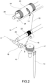
figure 2 shows a perspective view schematically showing components of a workstation of the open end spinning machine offigure 1 ; -
figures 3-4 show perspective views, with different details, of a spinning rotor with relative bearings of the spinning machine offigure 1 ; -
figure 5 shows a complete spinning rotor, composed ofrotor cup 18, the rotor shaft with is directly the inner ring of the bearings/bearingrows - The elements or parts of elements common to the embodiments described below will be indicated using the same reference numerals.
- With reference to the aforementioned figures,
reference numeral 4 globally denotes an open-end spinning machine. - The open-
end spinning machine 4 comprises at least oneworkstation 8 or unit; each workstation orunit 8 comprises an open-end spinning device 12 and awinding device 13. As known, in each open-end spinning device 12 afiber sliver 14 is drawn up from a respective spinning can (not shown) and is spun into ayarn 15. The yarn is subsequently wound on the windingdevice 13 to form a package (or cross-wound cone), not shown in the drawings. - In each workstation, an
opening roller 17 is provided, which opens thefiber sliver 14 to form individual fibers. The individual fibers are then fed to aspinning rotor 18, which turns them into ayarn 15. - Each package is frictionally driven for rotation by a
winding drum 19. Thewinding drums 19 are arranged on awinding shaft 20. - The workstations each have a yarn take-
up roller 22 arranged on a take-up drive shaft 23. - A yarn traversing device 24, which comprises a
yarn guide 25, is provided in eachworkstation 8. Theyarn guide 25 is controlled for longitudinal reciprocating motion through ayarn guide rod 26. - Additionally, the spinning machine may be equipped with several other devices (not described herein), for example a system for changing automatically the finished yarn packages. The workstations may each be equipped with a piecing device. The spinning machine may be also equipped with a system for automated piecing.
- As explained above, the
working station 8 is provided with anopening roller 17 configured to open afiber sliver 14 to form individual fibers and aspinning rotor 18 for turning the individual fibers into ayarn 15. - In particular, the
spinning rotor 18 is housed within a casing 28 and is rotatably supported, around a rotating axis X-X, by at least one bearing 36,40, in particular a first bearing 36 and a second bearing 40, or two different rows ofbearings - The
rotor bearings - The definition of bearing should be considered in a general and non-limiting sense.
- For example, the bearings may comprise a unique cage supporting two or more rows of balls/roller elements, or different, spaced apart, cages supporting rows of balls/roller bearings.
- Advantageously, the casing 28 comprises a first clamp 42 and a second clamp 44 divided in correspondence of a mean plane M and supporting said
bearings - Said clamps 42,44 are connected each other by means of removable fixing means 48 acting on the first clamp 42 and pressing it against an external fixed
lateral surface 68 of thebearings - The first and second clamps 42,44 may touch in correspondence of
respective abutments 52, diametrically opposite with respect to a vertical plane V, perpendicular to the mean plane M and passing through the rotating axis X-X. - Said clamps 42,44 are preferably displaced symmetrically with respect to said vertical plane V.
- According to a possible embodiment, said removable fixing means 48 comprises elastic means 54 in order to ensure a resilient pressing and mounting of the at least one bearing 36,40 inserted between the clamps 42,44.
- According to an embodiment, said elastic means 54 comprise elastic bushes 55, each elastic bush 55 being clamped around the external fixed
lateral surface 68 of acorresponding bearing - Preferably, the removable fixing means 48 comprises a presser 56 which urges the first clamp 42 against the second clamp 44.
- For example, said presser 56 comprises a self-fixing eccentric pin 60, rotatable in order to set the clamping force between clamps 42,44.
- Preferably said self-fixing eccentric pin 60 is displaced along a transversal axis Y-Y, perpendicular to the rotating axis X-X; moreover, said self-fixing eccentric pin 60 is preferably displaced above first clamp 42, in order to push first clamp 42 against second clamp 44.
- Preferably, said self-fixing eccentric pin 60 is displaced between a first and a second rotor bearing 36,40, along the rotating axis X-X.
- According to a possible embodiment, the self-fixing eccentric pin 60 is connected to an operating lever in order to set and fix the angular orientation of the pin itself and the pressing force between clamps 42,44.
- Each clamp 42,44 is counter-shaped with respect to an external fixed
lateral surface 68 of thecorresponding bearing - Preferably, the first clamp 42 surrounds at least 60% of said external fixed
lateral surface 68 of each rotor bearing 36,40. - More preferably, the first clamp 42 surrounds at least 80% of the external fixed
lateral surface 68 of each rotor bearing 36,40. - According to an embodiment, said first clamp 42 is connected to the removable fixing means 48 while the second clamp 44 is fixed to the casing 28.
- Above description relates to a
single workstation 8, but present invention applies to an open-end spinning machine 4 comprising a plurality ofworkstations 8 arranged side by side in at least one row, each workstation comprising aspinning rotor 18 with relative clamps 42,44,bearings - As it can be inferred from the description, the open end spinning machine according to the invention overcomes the drawbacks mentioned with reference to the cited prior art.
- In particular, the present invention fixes the rotor bearing/mounting system in the rotor housing evenly: the rows of the bearings are fixed and pressed with the same pressure to have an equal situation of forces.
- The solution is built as two saucer-type or "half-moon" parts, wherein one part/half-shell is integrated or applied into the rotor housing and the other part/half-shell is separate, slight flexible in movement to ensure the clamping with a further device.
- The geometries of the two "half-moon" parts ensure, that the force generated by the clamping is "guide" equal to the areas of the ball rows.
- The present invention ensures precise clamping by a fixing geometry which is preferred build as saucer-type/"half-moon" parts. Such a geometry ensures a guidance of the fixing/clamping force symmetrically/equal in to the areas of the bearing grooves (balls or other rolling elements).
- Therefore, the fixing of the clamping force ensures a safe and stable position of the rolling elements during spinning.
- Moreover, the interposition of elastic means between the clamps and the external fixed lateral surface of the bearings allows to dampen vibrations of the spinning rotor.
- Moreover, the elastic means allow to avoid peaks of mechanical stresses on the bearings of the rotor shaft during different working conditions (and also in case of shock against the rotor itself).
- Moreover, the present invention allows, when clamping is realized, an easy exchange of the rotor shaft /bearing system: in fact the bearing system, including the resilient mounting, can be easily removed without special tools, for example by using eccentric pin operated by the lever.
- The main difference between prior art and the new solution is that the old rotor housing has a free end-part, far from the rotor axis, what creates not stable loading position to the bearing.
- The new solution of rotor housing is more symmetrical from the view of rotor axis, so the distribution of loaded forces is better and even.
- Moreover, both sides of the resilient mounting are fixed by defined forces which are easily set-able by the user.
- The clamp is more than 80% of rounds by half-noon shape.
- Moreover, the releasing of clamping force of the rotor bearing can be made by self-fixing eccentric pin. Moreover, said self-fixing eccentric pin can be handled without tool (hand only) for a quicker maintenance of the rotor bearing.
Claims (16)
- An open-end spinning machine (4) comprising at least one workstation (8) provided with- an opening roller (17) configured to open a fiber sliver (14) to form individual fibers,- a spinning rotor (18) for turning the individual fibers into a yarn (15),- wherein the spinning rotor (18) is housed within a casing (28) and is rotatably supported, around a rotating axis (X-X), by at least one bearing (36,40), characterised in that- the casing (28) comprises a first and a second clamp (42,44) divided in correspondence of a mean plane (M) and supporting said at least one bearing (36,40),- said clamps (42,44) are connected to each other by means of removable fixing means (48) acting on the first clamp (42) and pressing it against an external fixed lateral surface (68) of the at least one bearing (36,40),- wherein said removable fixing means (48) comprise elastic means (54) in order to ensure a resilient pressing and mounting of the at least one bearing (36,40) inserted between the clamps (42,44).
- An open-end spinning machine (4) according to claim 1, wherein said elastic means (54) comprise elastic bushes (55), each elastic bush (55) being clamped around the external fixed lateral surface (68) of a corresponding bearing (36,40).
- An open-end spinning machine (4) according to claim 1 or 2, wherein the removable fixing means (48) comprises a presser (56) which urges the first clamp (42) against the second clamp (44).
- An open-end spinning machine (4) according to claim 3, wherein said presser (56) comprises a self-fixing eccentric pin (60), rotatable in order to set the clamping force between first and second clamp (42,44).
- An open-end spinning machine (4) according to claim 4, wherein said self-fixing eccentric pin (60) is displaced along a transversal axis (Y-Y), perpendicular to the rotating axis (X-X).
- An open-end spinning machine (4) according to any one of claims from 4 to 5, wherein said self-fixing eccentric pin (60) is displaced between a first and a second rotor bearing (36,40), along the rotating axis (X-X) .
- An open-end spinning machine (4) according to any one of claims from 4 to 6, wherein the self-fixing eccentric pin (60) is connected to an operating lever in order to set and fix the angular orientation of the self-fixing eccentric pin (60) and the pressing force between first and second clamp (42,44).
- An open-end spinning machine (4) according to any one of claims from 4 to 7, wherein said self-fixing eccentric pin (60) is displaced above first clamp (42), in order to push the first clamp (42) against the second clamp (44) .
- An open-end spinning machine (4) according to any one of claims from 1 to 8, wherein the first and second clamp (42,44) are counter-shaped with respect to the external fixed lateral surface (68) of the corresponding at least one bearing (36,40).
- An open-end spinning machine (4) according to any one of previous claims, wherein the first clamp (42) surrounds at least 60% of the external fixed lateral surface (68) of each rotor bearing (36,40).
- An open-end spinning machine (4) according to any one of previous claims, wherein the first clamp (42) surrounds at least 80% of the external fixed lateral surface (68) of each rotor bearing (36,40).
- An open-end spinning machine (4) according to any one of previous claims, wherein said second clamp (44) is fixed to the casing (28).
- An open-end spinning machine (4) according to any one of previous claims, wherein the first clamp (42) is connected to the removable fixing means (48).
- An open-end spinning machine (4) according to any one of previous claims, wherein said first and second clamp (42,44) are displaced symmetrically with respect to a vertical plane (V) perpendicular to the mean plane M and passing through the rotating axis (X-X).
- An open-end spinning machine (4) according to any one of previous claims, wherein the at least one bearing (36,40) comprise ball bearings, roller bearings and/or needle bearings.
- An open-end spinning machine (4) according to any one of previous claims, comprising a plurality of workstations (8) arranged side by side in at least one row, each workstation (8) comprising a spinning rotor (18) with relative first and second clamps (42,44), at least one bearing (36,40) and removable fixing means (48) according to any one of previous claims.
Applications Claiming Priority (1)
| Application Number | Priority Date | Filing Date | Title |
|---|---|---|---|
| IT102017000064193A IT201700064193A1 (en) | 2017-06-09 | 2017-06-09 | Open-end spinning machine with improved fixing of the spinning support bearings |
Publications (2)
| Publication Number | Publication Date |
|---|---|
| EP3412806A1 EP3412806A1 (en) | 2018-12-12 |
| EP3412806B1 true EP3412806B1 (en) | 2022-03-23 |
Family
ID=60020532
Family Applications (1)
| Application Number | Title | Priority Date | Filing Date |
|---|---|---|---|
| EP18173417.9A Active EP3412806B1 (en) | 2017-06-09 | 2018-05-21 | An open end spinning machine with improved fixing of the bearings supporting the spinning rotor |
Country Status (3)
| Country | Link |
|---|---|
| EP (1) | EP3412806B1 (en) |
| CN (2) | CN109023611B (en) |
| IT (1) | IT201700064193A1 (en) |
Families Citing this family (2)
| Publication number | Priority date | Publication date | Assignee | Title |
|---|---|---|---|---|
| IT201700064193A1 (en) * | 2017-06-09 | 2018-12-09 | Savio Macch Tessili Spa | Open-end spinning machine with improved fixing of the spinning support bearings |
| EP3754059A1 (en) * | 2019-06-17 | 2020-12-23 | Saurer Czech s.r.o. | Divided housing with a rotor assembly of a rotor spinning machine and method for installing a rotor assembly in a housing of a rotor spinning machine |
Family Cites Families (14)
| Publication number | Priority date | Publication date | Assignee | Title |
|---|---|---|---|---|
| CH527290A (en) * | 1970-08-03 | 1972-08-31 | Skf Kugellagerfabriken Gmbh | Bearing arrangement for spinning turbines |
| DE2130688B2 (en) * | 1971-06-21 | 1973-05-24 | Schubert & Salzer Maschinenfabrik Ag, 8070 Ingolstadt | OPEN-END SPINNING DEVICE |
| US3972171A (en) * | 1971-06-21 | 1976-08-03 | Schubert & Salzer Maschinenfabrik Aktiengesellschaft | Housing construction for open end spinning machines |
| JPS5233689B2 (en) * | 1973-01-29 | 1977-08-30 | ||
| JPS5335219U (en) * | 1976-08-27 | 1978-03-28 | ||
| US4254614A (en) * | 1978-10-18 | 1981-03-10 | Kabushiki Kaisha Toyoda Jidoshokki Seisakusho | Device for supporting a spindle of an open-end spinning frame |
| CS249814B1 (en) * | 1985-03-28 | 1987-04-16 | Frantisek Kriz | Resilient mounting of electric spindle |
| DE19637598C2 (en) * | 1996-09-16 | 1998-09-03 | Gerhard Dipl Ing Wanger | Arrangement for gas storage of a fast rotating shaft |
| DE102004007758A1 (en) * | 2004-02-18 | 2005-09-08 | Texparts Gmbh | High speed rotor bearing for open ended spinning rotor has screw retention holder |
| JP5687538B2 (en) * | 2011-03-28 | 2015-03-18 | 株式会社山田製作所 | Steering device |
| CN202576711U (en) * | 2012-04-23 | 2012-12-05 | 上海淳瑞机械科技有限公司 | Shock-absorbing bushing structure of rotor spinning machine |
| CN202705591U (en) * | 2012-05-16 | 2013-01-30 | 上海淳瑞机械科技有限公司 | Rotor locking mechanism of rotor spinning machine |
| CN103409862B (en) * | 2013-08-22 | 2015-11-18 | 宁波冠蓝机械科技有限公司 | A kind of revolving cup gap adjustment structure of rotor spinning machine |
| IT201700064193A1 (en) * | 2017-06-09 | 2018-12-09 | Savio Macch Tessili Spa | Open-end spinning machine with improved fixing of the spinning support bearings |
-
2017
- 2017-06-09 IT IT102017000064193A patent/IT201700064193A1/en unknown
-
2018
- 2018-05-21 EP EP18173417.9A patent/EP3412806B1/en active Active
- 2018-06-08 CN CN201810589114.2A patent/CN109023611B/en not_active Expired - Fee Related
- 2018-06-08 CN CN201820891782.6U patent/CN208733276U/en not_active Withdrawn - After Issue
Also Published As
| Publication number | Publication date |
|---|---|
| CN208733276U (en) | 2019-04-12 |
| IT201700064193A1 (en) | 2018-12-09 |
| CN109023611A (en) | 2018-12-18 |
| EP3412806A1 (en) | 2018-12-12 |
| CN109023611B (en) | 2022-05-10 |
Similar Documents
| Publication | Publication Date | Title |
|---|---|---|
| CN101437741B (en) | Clamping device | |
| EP3412806A1 (en) | An open end spinning machine with improved fixing of the bearings supporting the spinning rotor | |
| US4773210A (en) | Open-end rotor-spinning device | |
| CN102070045A (en) | Coil holder | |
| CN101899730B (en) | Thread trapper device for a spindle of a spinning or thread machine | |
| CS718483A2 (en) | Method of yarn spinning-in and yarn packages doffing on textile machine | |
| CZ286244B6 (en) | Paraffining apparatus | |
| CN107488898A (en) | Wire-clamping device | |
| US3595002A (en) | Twisting and forming device for textile spinning and twisting machines | |
| CN107428490B (en) | Winding spindle | |
| US3327466A (en) | Center-of-gravity spindle device | |
| JP7473295B2 (en) | Take-up winder | |
| US3430892A (en) | Creel adapter for filamentary material processing apparatus | |
| CZ2018645A3 (en) | Spindle of a ring spinning machine | |
| KR20020089185A (en) | Yarn winding apparatus and method of producing a yarn package | |
| US20240286865A1 (en) | Sleeve plate | |
| US3546871A (en) | Damped support for double twist spindle | |
| US2794517A (en) | Traverse cam lubrication | |
| JP2740279B2 (en) | Automatic switching winding machine for yarn | |
| CN111527039B (en) | Winding machine | |
| JPH0794309B2 (en) | Bobbin holder | |
| JP2003081532A (en) | Bobbin holder | |
| US3693338A (en) | Twist frame apparatus | |
| TWI631247B (en) | Drafting arrangement for drawing a roving yarn | |
| EP3754059A1 (en) | Divided housing with a rotor assembly of a rotor spinning machine and method for installing a rotor assembly in a housing of a rotor spinning machine |
Legal Events
| Date | Code | Title | Description |
|---|---|---|---|
| PUAI | Public reference made under article 153(3) epc to a published international application that has entered the european phase |
Free format text: ORIGINAL CODE: 0009012 |
|
| STAA | Information on the status of an ep patent application or granted ep patent |
Free format text: STATUS: THE APPLICATION HAS BEEN PUBLISHED |
|
| AK | Designated contracting states |
Kind code of ref document: A1 Designated state(s): AL AT BE BG CH CY CZ DE DK EE ES FI FR GB GR HR HU IE IS IT LI LT LU LV MC MK MT NL NO PL PT RO RS SE SI SK SM TR |
|
| AX | Request for extension of the european patent |
Extension state: BA ME |
|
| STAA | Information on the status of an ep patent application or granted ep patent |
Free format text: STATUS: REQUEST FOR EXAMINATION WAS MADE |
|
| 17P | Request for examination filed |
Effective date: 20190607 |
|
| RBV | Designated contracting states (corrected) |
Designated state(s): AL AT BE BG CH CY CZ DE DK EE ES FI FR GB GR HR HU IE IS IT LI LT LU LV MC MK MT NL NO PL PT RO RS SE SI SK SM TR |
|
| RIC1 | Information provided on ipc code assigned before grant |
Ipc: D01H 4/12 20060101AFI20210830BHEP |
|
| GRAP | Despatch of communication of intention to grant a patent |
Free format text: ORIGINAL CODE: EPIDOSNIGR1 |
|
| STAA | Information on the status of an ep patent application or granted ep patent |
Free format text: STATUS: GRANT OF PATENT IS INTENDED |
|
| INTG | Intention to grant announced |
Effective date: 20211119 |
|
| GRAS | Grant fee paid |
Free format text: ORIGINAL CODE: EPIDOSNIGR3 |
|
| GRAA | (expected) grant |
Free format text: ORIGINAL CODE: 0009210 |
|
| STAA | Information on the status of an ep patent application or granted ep patent |
Free format text: STATUS: THE PATENT HAS BEEN GRANTED |
|
| AK | Designated contracting states |
Kind code of ref document: B1 Designated state(s): AL AT BE BG CH CY CZ DE DK EE ES FI FR GB GR HR HU IE IS IT LI LT LU LV MC MK MT NL NO PL PT RO RS SE SI SK SM TR |
|
| REG | Reference to a national code |
Ref country code: GB Ref legal event code: FG4D |
|
| REG | Reference to a national code |
Ref country code: CH Ref legal event code: EP |
|
| REG | Reference to a national code |
Ref country code: IE Ref legal event code: FG4D |
|
| REG | Reference to a national code |
Ref country code: DE Ref legal event code: R096 Ref document number: 602018032527 Country of ref document: DE |
|
| REG | Reference to a national code |
Ref country code: AT Ref legal event code: REF Ref document number: 1477496 Country of ref document: AT Kind code of ref document: T Effective date: 20220415 |
|
| REG | Reference to a national code |
Ref country code: LT Ref legal event code: MG9D |
|
| REG | Reference to a national code |
Ref country code: NL Ref legal event code: MP Effective date: 20220323 |
|
| PG25 | Lapsed in a contracting state [announced via postgrant information from national office to epo] |
Ref country code: SE Free format text: LAPSE BECAUSE OF FAILURE TO SUBMIT A TRANSLATION OF THE DESCRIPTION OR TO PAY THE FEE WITHIN THE PRESCRIBED TIME-LIMIT Effective date: 20220323 Ref country code: RS Free format text: LAPSE BECAUSE OF FAILURE TO SUBMIT A TRANSLATION OF THE DESCRIPTION OR TO PAY THE FEE WITHIN THE PRESCRIBED TIME-LIMIT Effective date: 20220323 Ref country code: NO Free format text: LAPSE BECAUSE OF FAILURE TO SUBMIT A TRANSLATION OF THE DESCRIPTION OR TO PAY THE FEE WITHIN THE PRESCRIBED TIME-LIMIT Effective date: 20220623 Ref country code: LT Free format text: LAPSE BECAUSE OF FAILURE TO SUBMIT A TRANSLATION OF THE DESCRIPTION OR TO PAY THE FEE WITHIN THE PRESCRIBED TIME-LIMIT Effective date: 20220323 Ref country code: HR Free format text: LAPSE BECAUSE OF FAILURE TO SUBMIT A TRANSLATION OF THE DESCRIPTION OR TO PAY THE FEE WITHIN THE PRESCRIBED TIME-LIMIT Effective date: 20220323 Ref country code: BG Free format text: LAPSE BECAUSE OF FAILURE TO SUBMIT A TRANSLATION OF THE DESCRIPTION OR TO PAY THE FEE WITHIN THE PRESCRIBED TIME-LIMIT Effective date: 20220623 |
|
| REG | Reference to a national code |
Ref country code: AT Ref legal event code: MK05 Ref document number: 1477496 Country of ref document: AT Kind code of ref document: T Effective date: 20220323 |
|
| PG25 | Lapsed in a contracting state [announced via postgrant information from national office to epo] |
Ref country code: LV Free format text: LAPSE BECAUSE OF FAILURE TO SUBMIT A TRANSLATION OF THE DESCRIPTION OR TO PAY THE FEE WITHIN THE PRESCRIBED TIME-LIMIT Effective date: 20220323 Ref country code: GR Free format text: LAPSE BECAUSE OF FAILURE TO SUBMIT A TRANSLATION OF THE DESCRIPTION OR TO PAY THE FEE WITHIN THE PRESCRIBED TIME-LIMIT Effective date: 20220624 Ref country code: FI Free format text: LAPSE BECAUSE OF FAILURE TO SUBMIT A TRANSLATION OF THE DESCRIPTION OR TO PAY THE FEE WITHIN THE PRESCRIBED TIME-LIMIT Effective date: 20220323 |
|
| PG25 | Lapsed in a contracting state [announced via postgrant information from national office to epo] |
Ref country code: NL Free format text: LAPSE BECAUSE OF FAILURE TO SUBMIT A TRANSLATION OF THE DESCRIPTION OR TO PAY THE FEE WITHIN THE PRESCRIBED TIME-LIMIT Effective date: 20220323 |
|
| PG25 | Lapsed in a contracting state [announced via postgrant information from national office to epo] |
Ref country code: SM Free format text: LAPSE BECAUSE OF FAILURE TO SUBMIT A TRANSLATION OF THE DESCRIPTION OR TO PAY THE FEE WITHIN THE PRESCRIBED TIME-LIMIT Effective date: 20220323 Ref country code: SK Free format text: LAPSE BECAUSE OF FAILURE TO SUBMIT A TRANSLATION OF THE DESCRIPTION OR TO PAY THE FEE WITHIN THE PRESCRIBED TIME-LIMIT Effective date: 20220323 Ref country code: RO Free format text: LAPSE BECAUSE OF FAILURE TO SUBMIT A TRANSLATION OF THE DESCRIPTION OR TO PAY THE FEE WITHIN THE PRESCRIBED TIME-LIMIT Effective date: 20220323 Ref country code: PT Free format text: LAPSE BECAUSE OF FAILURE TO SUBMIT A TRANSLATION OF THE DESCRIPTION OR TO PAY THE FEE WITHIN THE PRESCRIBED TIME-LIMIT Effective date: 20220725 Ref country code: ES Free format text: LAPSE BECAUSE OF FAILURE TO SUBMIT A TRANSLATION OF THE DESCRIPTION OR TO PAY THE FEE WITHIN THE PRESCRIBED TIME-LIMIT Effective date: 20220323 Ref country code: EE Free format text: LAPSE BECAUSE OF FAILURE TO SUBMIT A TRANSLATION OF THE DESCRIPTION OR TO PAY THE FEE WITHIN THE PRESCRIBED TIME-LIMIT Effective date: 20220323 Ref country code: CZ Free format text: LAPSE BECAUSE OF FAILURE TO SUBMIT A TRANSLATION OF THE DESCRIPTION OR TO PAY THE FEE WITHIN THE PRESCRIBED TIME-LIMIT Effective date: 20220323 Ref country code: AT Free format text: LAPSE BECAUSE OF FAILURE TO SUBMIT A TRANSLATION OF THE DESCRIPTION OR TO PAY THE FEE WITHIN THE PRESCRIBED TIME-LIMIT Effective date: 20220323 |
|
| PG25 | Lapsed in a contracting state [announced via postgrant information from national office to epo] |
Ref country code: PL Free format text: LAPSE BECAUSE OF FAILURE TO SUBMIT A TRANSLATION OF THE DESCRIPTION OR TO PAY THE FEE WITHIN THE PRESCRIBED TIME-LIMIT Effective date: 20220323 Ref country code: IS Free format text: LAPSE BECAUSE OF FAILURE TO SUBMIT A TRANSLATION OF THE DESCRIPTION OR TO PAY THE FEE WITHIN THE PRESCRIBED TIME-LIMIT Effective date: 20220723 Ref country code: AL Free format text: LAPSE BECAUSE OF FAILURE TO SUBMIT A TRANSLATION OF THE DESCRIPTION OR TO PAY THE FEE WITHIN THE PRESCRIBED TIME-LIMIT Effective date: 20220323 |
|
| REG | Reference to a national code |
Ref country code: DE Ref legal event code: R119 Ref document number: 602018032527 Country of ref document: DE |
|
| REG | Reference to a national code |
Ref country code: CH Ref legal event code: PL |
|
| REG | Reference to a national code |
Ref country code: BE Ref legal event code: MM Effective date: 20220531 |
|
| PLBE | No opposition filed within time limit |
Free format text: ORIGINAL CODE: 0009261 |
|
| STAA | Information on the status of an ep patent application or granted ep patent |
Free format text: STATUS: NO OPPOSITION FILED WITHIN TIME LIMIT |
|
| PG25 | Lapsed in a contracting state [announced via postgrant information from national office to epo] |
Ref country code: MC Free format text: LAPSE BECAUSE OF FAILURE TO SUBMIT A TRANSLATION OF THE DESCRIPTION OR TO PAY THE FEE WITHIN THE PRESCRIBED TIME-LIMIT Effective date: 20220323 Ref country code: LU Free format text: LAPSE BECAUSE OF NON-PAYMENT OF DUE FEES Effective date: 20220521 Ref country code: LI Free format text: LAPSE BECAUSE OF NON-PAYMENT OF DUE FEES Effective date: 20220531 Ref country code: DK Free format text: LAPSE BECAUSE OF FAILURE TO SUBMIT A TRANSLATION OF THE DESCRIPTION OR TO PAY THE FEE WITHIN THE PRESCRIBED TIME-LIMIT Effective date: 20220323 Ref country code: CH Free format text: LAPSE BECAUSE OF NON-PAYMENT OF DUE FEES Effective date: 20220531 |
|
| 26N | No opposition filed |
Effective date: 20230102 |
|
| GBPC | Gb: european patent ceased through non-payment of renewal fee |
Effective date: 20220623 |
|
| PG25 | Lapsed in a contracting state [announced via postgrant information from national office to epo] |
Ref country code: IE Free format text: LAPSE BECAUSE OF NON-PAYMENT OF DUE FEES Effective date: 20220521 Ref country code: FR Free format text: LAPSE BECAUSE OF NON-PAYMENT OF DUE FEES Effective date: 20220523 |
|
| PG25 | Lapsed in a contracting state [announced via postgrant information from national office to epo] |
Ref country code: SI Free format text: LAPSE BECAUSE OF FAILURE TO SUBMIT A TRANSLATION OF THE DESCRIPTION OR TO PAY THE FEE WITHIN THE PRESCRIBED TIME-LIMIT Effective date: 20220323 Ref country code: GB Free format text: LAPSE BECAUSE OF NON-PAYMENT OF DUE FEES Effective date: 20220623 Ref country code: DE Free format text: LAPSE BECAUSE OF NON-PAYMENT OF DUE FEES Effective date: 20221201 Ref country code: BE Free format text: LAPSE BECAUSE OF NON-PAYMENT OF DUE FEES Effective date: 20220531 |
|
| P01 | Opt-out of the competence of the unified patent court (upc) registered |
Effective date: 20230526 |
|
| PG25 | Lapsed in a contracting state [announced via postgrant information from national office to epo] |
Ref country code: HU Free format text: LAPSE BECAUSE OF FAILURE TO SUBMIT A TRANSLATION OF THE DESCRIPTION OR TO PAY THE FEE WITHIN THE PRESCRIBED TIME-LIMIT; INVALID AB INITIO Effective date: 20180521 |
|
| PG25 | Lapsed in a contracting state [announced via postgrant information from national office to epo] |
Ref country code: MK Free format text: LAPSE BECAUSE OF FAILURE TO SUBMIT A TRANSLATION OF THE DESCRIPTION OR TO PAY THE FEE WITHIN THE PRESCRIBED TIME-LIMIT Effective date: 20220323 Ref country code: CY Free format text: LAPSE BECAUSE OF FAILURE TO SUBMIT A TRANSLATION OF THE DESCRIPTION OR TO PAY THE FEE WITHIN THE PRESCRIBED TIME-LIMIT Effective date: 20220323 |
|
| PGFP | Annual fee paid to national office [announced via postgrant information from national office to epo] |
Ref country code: IT Payment date: 20240305 Year of fee payment: 7 |
|
| PGFP | Annual fee paid to national office [announced via postgrant information from national office to epo] |
Ref country code: TR Payment date: 20240521 Year of fee payment: 7 |
|
| PG25 | Lapsed in a contracting state [announced via postgrant information from national office to epo] |
Ref country code: MT Free format text: LAPSE BECAUSE OF FAILURE TO SUBMIT A TRANSLATION OF THE DESCRIPTION OR TO PAY THE FEE WITHIN THE PRESCRIBED TIME-LIMIT Effective date: 20220323 |
|
| PG25 | Lapsed in a contracting state [announced via postgrant information from national office to epo] |
Ref country code: IT Free format text: LAPSE BECAUSE OF NON-PAYMENT OF DUE FEES Effective date: 20250521 |