EP3412733A1 - Thermally conductive molded resin article - Google Patents
Thermally conductive molded resin article Download PDFInfo
- Publication number
- EP3412733A1 EP3412733A1 EP17747393.1A EP17747393A EP3412733A1 EP 3412733 A1 EP3412733 A1 EP 3412733A1 EP 17747393 A EP17747393 A EP 17747393A EP 3412733 A1 EP3412733 A1 EP 3412733A1
- Authority
- EP
- European Patent Office
- Prior art keywords
- thermally conductive
- conductive filler
- resin
- molded resin
- vol
- Prior art date
- Legal status (The legal status is an assumption and is not a legal conclusion. Google has not performed a legal analysis and makes no representation as to the accuracy of the status listed.)
- Granted
Links
Images
Classifications
-
- C—CHEMISTRY; METALLURGY
- C08—ORGANIC MACROMOLECULAR COMPOUNDS; THEIR PREPARATION OR CHEMICAL WORKING-UP; COMPOSITIONS BASED THEREON
- C08K—Use of inorganic or non-macromolecular organic substances as compounding ingredients
- C08K3/00—Use of inorganic substances as compounding ingredients
- C08K3/01—Use of inorganic substances as compounding ingredients characterized by their specific function
- C08K3/013—Fillers, pigments or reinforcing additives
-
- C—CHEMISTRY; METALLURGY
- C08—ORGANIC MACROMOLECULAR COMPOUNDS; THEIR PREPARATION OR CHEMICAL WORKING-UP; COMPOSITIONS BASED THEREON
- C08K—Use of inorganic or non-macromolecular organic substances as compounding ingredients
- C08K3/00—Use of inorganic substances as compounding ingredients
- C08K3/38—Boron-containing compounds
-
- C—CHEMISTRY; METALLURGY
- C08—ORGANIC MACROMOLECULAR COMPOUNDS; THEIR PREPARATION OR CHEMICAL WORKING-UP; COMPOSITIONS BASED THEREON
- C08K—Use of inorganic or non-macromolecular organic substances as compounding ingredients
- C08K3/00—Use of inorganic substances as compounding ingredients
-
- C—CHEMISTRY; METALLURGY
- C08—ORGANIC MACROMOLECULAR COMPOUNDS; THEIR PREPARATION OR CHEMICAL WORKING-UP; COMPOSITIONS BASED THEREON
- C08K—Use of inorganic or non-macromolecular organic substances as compounding ingredients
- C08K3/00—Use of inorganic substances as compounding ingredients
- C08K3/18—Oxygen-containing compounds, e.g. metal carbonyls
- C08K3/20—Oxides; Hydroxides
- C08K3/22—Oxides; Hydroxides of metals
-
- C—CHEMISTRY; METALLURGY
- C08—ORGANIC MACROMOLECULAR COMPOUNDS; THEIR PREPARATION OR CHEMICAL WORKING-UP; COMPOSITIONS BASED THEREON
- C08L—COMPOSITIONS OF MACROMOLECULAR COMPOUNDS
- C08L27/00—Compositions of homopolymers or copolymers of compounds having one or more unsaturated aliphatic radicals, each having only one carbon-to-carbon double bond, and at least one being terminated by a halogen; Compositions of derivatives of such polymers
- C08L27/02—Compositions of homopolymers or copolymers of compounds having one or more unsaturated aliphatic radicals, each having only one carbon-to-carbon double bond, and at least one being terminated by a halogen; Compositions of derivatives of such polymers not modified by chemical after-treatment
- C08L27/12—Compositions of homopolymers or copolymers of compounds having one or more unsaturated aliphatic radicals, each having only one carbon-to-carbon double bond, and at least one being terminated by a halogen; Compositions of derivatives of such polymers not modified by chemical after-treatment containing fluorine atoms
-
- C—CHEMISTRY; METALLURGY
- C08—ORGANIC MACROMOLECULAR COMPOUNDS; THEIR PREPARATION OR CHEMICAL WORKING-UP; COMPOSITIONS BASED THEREON
- C08L—COMPOSITIONS OF MACROMOLECULAR COMPOUNDS
- C08L33/00—Compositions of homopolymers or copolymers of compounds having one or more unsaturated aliphatic radicals, each having only one carbon-to-carbon double bond, and only one being terminated by only one carboxyl radical, or of salts, anhydrides, esters, amides, imides or nitriles thereof; Compositions of derivatives of such polymers
- C08L33/04—Homopolymers or copolymers of esters
- C08L33/06—Homopolymers or copolymers of esters of esters containing only carbon, hydrogen and oxygen, which oxygen atoms are present only as part of the carboxyl radical
-
- C—CHEMISTRY; METALLURGY
- C08—ORGANIC MACROMOLECULAR COMPOUNDS; THEIR PREPARATION OR CHEMICAL WORKING-UP; COMPOSITIONS BASED THEREON
- C08L—COMPOSITIONS OF MACROMOLECULAR COMPOUNDS
- C08L33/00—Compositions of homopolymers or copolymers of compounds having one or more unsaturated aliphatic radicals, each having only one carbon-to-carbon double bond, and only one being terminated by only one carboxyl radical, or of salts, anhydrides, esters, amides, imides or nitriles thereof; Compositions of derivatives of such polymers
- C08L33/04—Homopolymers or copolymers of esters
- C08L33/06—Homopolymers or copolymers of esters of esters containing only carbon, hydrogen and oxygen, which oxygen atoms are present only as part of the carboxyl radical
- C08L33/08—Homopolymers or copolymers of acrylic acid esters
-
- C—CHEMISTRY; METALLURGY
- C08—ORGANIC MACROMOLECULAR COMPOUNDS; THEIR PREPARATION OR CHEMICAL WORKING-UP; COMPOSITIONS BASED THEREON
- C08L—COMPOSITIONS OF MACROMOLECULAR COMPOUNDS
- C08L83/00—Compositions of macromolecular compounds obtained by reactions forming in the main chain of the macromolecule a linkage containing silicon with or without sulfur, nitrogen, oxygen or carbon only; Compositions of derivatives of such polymers
-
- C—CHEMISTRY; METALLURGY
- C08—ORGANIC MACROMOLECULAR COMPOUNDS; THEIR PREPARATION OR CHEMICAL WORKING-UP; COMPOSITIONS BASED THEREON
- C08L—COMPOSITIONS OF MACROMOLECULAR COMPOUNDS
- C08L83/00—Compositions of macromolecular compounds obtained by reactions forming in the main chain of the macromolecule a linkage containing silicon with or without sulfur, nitrogen, oxygen or carbon only; Compositions of derivatives of such polymers
- C08L83/04—Polysiloxanes
-
- C—CHEMISTRY; METALLURGY
- C09—DYES; PAINTS; POLISHES; NATURAL RESINS; ADHESIVES; COMPOSITIONS NOT OTHERWISE PROVIDED FOR; APPLICATIONS OF MATERIALS NOT OTHERWISE PROVIDED FOR
- C09K—MATERIALS FOR MISCELLANEOUS APPLICATIONS, NOT PROVIDED FOR ELSEWHERE
- C09K5/00—Heat-transfer, heat-exchange or heat-storage materials, e.g. refrigerants; Materials for the production of heat or cold by chemical reactions other than by combustion
- C09K5/08—Materials not undergoing a change of physical state when used
- C09K5/14—Solid materials, e.g. powdery or granular
-
- H—ELECTRICITY
- H10—SEMICONDUCTOR DEVICES; ELECTRIC SOLID-STATE DEVICES NOT OTHERWISE PROVIDED FOR
- H10H—INORGANIC LIGHT-EMITTING SEMICONDUCTOR DEVICES HAVING POTENTIAL BARRIERS
- H10H20/00—Individual inorganic light-emitting semiconductor devices having potential barriers, e.g. light-emitting diodes [LED]
- H10H20/80—Constructional details
- H10H20/85—Packages
- H10H20/858—Means for heat extraction or cooling
- H10H20/8581—Means for heat extraction or cooling characterised by their material
-
- H—ELECTRICITY
- H10—SEMICONDUCTOR DEVICES; ELECTRIC SOLID-STATE DEVICES NOT OTHERWISE PROVIDED FOR
- H10W—GENERIC PACKAGES, INTERCONNECTIONS, CONNECTORS OR OTHER CONSTRUCTIONAL DETAILS OF DEVICES COVERED BY CLASS H10
- H10W40/00—Arrangements for thermal protection or thermal control
- H10W40/70—Fillings or auxiliary members in containers or in encapsulations for thermal protection or control
-
- C—CHEMISTRY; METALLURGY
- C08—ORGANIC MACROMOLECULAR COMPOUNDS; THEIR PREPARATION OR CHEMICAL WORKING-UP; COMPOSITIONS BASED THEREON
- C08K—Use of inorganic or non-macromolecular organic substances as compounding ingredients
- C08K3/00—Use of inorganic substances as compounding ingredients
- C08K3/18—Oxygen-containing compounds, e.g. metal carbonyls
- C08K3/20—Oxides; Hydroxides
- C08K3/22—Oxides; Hydroxides of metals
- C08K2003/2227—Oxides; Hydroxides of metals of aluminium
-
- C—CHEMISTRY; METALLURGY
- C08—ORGANIC MACROMOLECULAR COMPOUNDS; THEIR PREPARATION OR CHEMICAL WORKING-UP; COMPOSITIONS BASED THEREON
- C08K—Use of inorganic or non-macromolecular organic substances as compounding ingredients
- C08K3/00—Use of inorganic substances as compounding ingredients
- C08K3/38—Boron-containing compounds
- C08K2003/382—Boron-containing compounds and nitrogen
-
- C—CHEMISTRY; METALLURGY
- C08—ORGANIC MACROMOLECULAR COMPOUNDS; THEIR PREPARATION OR CHEMICAL WORKING-UP; COMPOSITIONS BASED THEREON
- C08K—Use of inorganic or non-macromolecular organic substances as compounding ingredients
- C08K2201/00—Specific properties of additives
- C08K2201/001—Conductive additives
-
- C—CHEMISTRY; METALLURGY
- C08—ORGANIC MACROMOLECULAR COMPOUNDS; THEIR PREPARATION OR CHEMICAL WORKING-UP; COMPOSITIONS BASED THEREON
- C08K—Use of inorganic or non-macromolecular organic substances as compounding ingredients
- C08K2201/00—Specific properties of additives
- C08K2201/002—Physical properties
- C08K2201/005—Additives being defined by their particle size in general
-
- C—CHEMISTRY; METALLURGY
- C08—ORGANIC MACROMOLECULAR COMPOUNDS; THEIR PREPARATION OR CHEMICAL WORKING-UP; COMPOSITIONS BASED THEREON
- C08K—Use of inorganic or non-macromolecular organic substances as compounding ingredients
- C08K2201/00—Specific properties of additives
- C08K2201/014—Additives containing two or more different additives of the same subgroup in C08K
-
- C—CHEMISTRY; METALLURGY
- C08—ORGANIC MACROMOLECULAR COMPOUNDS; THEIR PREPARATION OR CHEMICAL WORKING-UP; COMPOSITIONS BASED THEREON
- C08K—Use of inorganic or non-macromolecular organic substances as compounding ingredients
- C08K2201/00—Specific properties of additives
- C08K2201/016—Additives defined by their aspect ratio
-
- H—ELECTRICITY
- H10—SEMICONDUCTOR DEVICES; ELECTRIC SOLID-STATE DEVICES NOT OTHERWISE PROVIDED FOR
- H10W—GENERIC PACKAGES, INTERCONNECTIONS, CONNECTORS OR OTHER CONSTRUCTIONAL DETAILS OF DEVICES COVERED BY CLASS H10
- H10W40/00—Arrangements for thermal protection or thermal control
- H10W40/20—Arrangements for cooling
- H10W40/25—Arrangements for cooling characterised by their materials
-
- H—ELECTRICITY
- H10—SEMICONDUCTOR DEVICES; ELECTRIC SOLID-STATE DEVICES NOT OTHERWISE PROVIDED FOR
- H10W—GENERIC PACKAGES, INTERCONNECTIONS, CONNECTORS OR OTHER CONSTRUCTIONAL DETAILS OF DEVICES COVERED BY CLASS H10
- H10W40/00—Arrangements for thermal protection or thermal control
- H10W40/20—Arrangements for cooling
- H10W40/25—Arrangements for cooling characterised by their materials
- H10W40/251—Organics
-
- H—ELECTRICITY
- H10—SEMICONDUCTOR DEVICES; ELECTRIC SOLID-STATE DEVICES NOT OTHERWISE PROVIDED FOR
- H10W—GENERIC PACKAGES, INTERCONNECTIONS, CONNECTORS OR OTHER CONSTRUCTIONAL DETAILS OF DEVICES COVERED BY CLASS H10
- H10W40/00—Arrangements for thermal protection or thermal control
- H10W40/20—Arrangements for cooling
- H10W40/25—Arrangements for cooling characterised by their materials
- H10W40/258—Metallic materials
-
- H—ELECTRICITY
- H10—SEMICONDUCTOR DEVICES; ELECTRIC SOLID-STATE DEVICES NOT OTHERWISE PROVIDED FOR
- H10W—GENERIC PACKAGES, INTERCONNECTIONS, CONNECTORS OR OTHER CONSTRUCTIONAL DETAILS OF DEVICES COVERED BY CLASS H10
- H10W40/00—Arrangements for thermal protection or thermal control
- H10W40/20—Arrangements for cooling
- H10W40/25—Arrangements for cooling characterised by their materials
- H10W40/259—Ceramics or glasses
Definitions
- the present invention relates to a thermally conductive molded resin article, particularly relates to a thermally conductive molded resin article that can be inexpensively mass-produced and that has excellent thermal conductivity in the thickness direction.
- thermally conductive molded resin article is utilized as a member that conducts heat efficiently between an exothermic body such as a chip and a heat releasing body such as a heat sink.
- a thermally conductive filler is oriented and dispersed in the resin in order to form a thermal conductive pass efficiently.
- a thermally conductive resin sheet that is inserted, in order to enhance heat releasing effect, between the electronic part and a heat releasing plate to make the thermal conductivity therebetween better and to improve the thermal conductivity in the thickness direction.
- Patent Literature 1 Japanese Patent Laid-Open Application H05-102355
- a thermally conductive filler which is surface-treated by coating with a coupling agent is included in a matrix component, and the thermally conductive filler is oriented and dispersed in the thickness direction.
- Patent Literature 2 Japanese Patent Laid-Open Application 2003-174127 .
- an anisotropic thermally conductive sheet where a surface of a thermally conductive fiber is coated with an electric insulating material, and the thermally conductive fiber is oriented in the thickness direction of the sheet made of an organic polymer by electrostatically flocking.
- the object of the present invention is to provide a thermally conductive molded resin article that can be inexpensively mass-produced and that exhibits a low thermal resistance value as a result of reducing internal thermal resistance by high filling and reducing interfacial thermal resistance by improving cutting precision.
- the inventors have found that, when using fillers having different smaller and larger average particle sizes as the thermally conductive fillers, and an aspect ratio of the thermally conductive filler having the larger average particle size is within the specific range and is oriented approximately in the thickness direction, the objects can be effectively solved, and have completed the present invention.
- a thermally conductive molded resin article which comprises a resin and thermally conductive fillers including a first thermally conductive filler and a second thermally conductive filler having a smaller particle size than the first thermally conductive filler;
- the first thermally conductive filler has an aspect ratio of 10 or more and is oriented approximately in the thickness direction of the thermally conductive molded resin article;
- the resin is a silicone resin, an acrylic rubber, or a fluororubber; and the second thermally conductive filler has a thermal conductivity of more than 5 W/mK.
- a volumetric filling factor of the thermally conductive filler in the thermally conductive molded resin article is preferably 10 to 80 % by volume, more preferably 40 to 60 % by volume.
- a weld line of the resin is formed approximately in the thickness direction of the thermally conductive molded resin article.
- the matter that the weld lines are formed approximately in the thickness direction of the thermally conductive molded article means that the thermally conductive molded article is formed by a many resin articles which are folded and welded in the perpendicular direction.
- the weld line may not only be a perfect straight line but also a curved like an arch, or may be partly discontinuous.
- the "thermally conductive molded resin article” in the present invention means the concept that includes a block-like article after extrusion molding, a sliced article which is sliced the block-like article properly (including sliced sheet-line article).
- the "particle size” is a concept of an average particle size in the particle size distribution measurement, and is measured by laser diffraction scattering method.
- thermoly conductive molded resin article that can be inexpensively mass-produced and that exhibits a low thermal resistance value as a result of reducing internal thermal resistance by high filling and reducing interfacial thermal resistance by improving cutting precision.
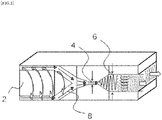
- Fig. 1 is a schematic view (side view of T die) to explain the producing method of the thermally conductive molded resin sheet which is one embodiment of the thermally conductive molded resin article of the present invention.
- thermally conductive molded resin article of the present invention will be explained in detail by referring drawings, but the present invention is not limited thereto. Furthermore, in the explanation hereafter, the same symbol is used for designating the same or corresponding part, and any redundant explanation may be omitted. In addition, since the drawing is presented to explain the concept of the present invention, there is a case where size or ratio is different from the real parts.
- the thermally conductive molded resin sheet of the present embodiment comprises a resin and thermally conductive fillers including a first thermally conductive filler and a second thermally conductive filler having a smaller particle size than the first thermally conductive filler, the first thermally conductive filler has an aspect ratio of 10 or more and is oriented approximately in the thickness direction of the thermally conductive molded resin article, and the resin is a silicone resin, an acrylic rubber, or a fluororubber.
- the thermally conductive molded resin sheet of the present embodiment comprises the resin and the thermally conductive fillers including the first thermally conductive filler and the second thermally conductive filler having a smaller particle size than the first thermally conductive filler.
- the particle size D 1 of the first thermally conductive filler and the particle size D 2 of the second thermally conductive filler has the relation of D 1 > D 2 . It may be allowable that thermally conductive fillers other than the first thermally conductive filler and the second thermally conductive filler can be used, as long as within the range that does not impair the effect of the present invention.
- FIG. 1 is a schematic view to explain the method for producing the thermally conductive molded resin sheet of the present embodiment, and shows a schematic sectional view of the top portion of an extruder and a T die.
- the T die of the extruder has a first gap of a gap X in the direction of up and down, a second gap of a gap Y in the direction of up and down which is continuous with the first gap, and an inclined surface on at least one of the upper and lower sides of a passage between the first gap and the second gap.
- a resin composition of the thermally conductive molded resin article which contains the thermally conductive filler is stirred and kneaded by a screw 2 to be introduced to the first gap 4 (gap X) along with a passage 8.
- the flow of the resin composition is squeezed in the direction of up and down (thickness direction) relative to the direction of the flow in the extruder through the first gap 4 to be a thin belt.
- the thermally conductive filler mixed in the resin orients in the flow direction of the resin composition. In this case, the thermally conductive filler orients in the direction of the surface of a thermally conductive resin sheet precursor.
- the gap of the first gap 4 can be adjusted properly, and is, for example, 0.5 mm or more and 5.0 mm or less.
- the gap of the first gap 4 is less than 0.5 mm, not only an extrusion pressure is unnecessarily increases but also the resin composition may be clogged.
- the gap of the first gap 4 is larger than 5.0 mm, a degree of orientation of the thermally conductive filler with respect to the surface direction of the resin sheet precursor becomes decreased.
- the thermally conductive fillers orients approximately in the thickness direction of the thermally conductive molded resin article (block-like article).
- the thermally conductive molded article (block-like article) which is crosslinked in the direction perpendicular to the orientating direction of the thermally conductive fillers to give a uniform thickness
- the thermally conductive molded resin article (sheet) of the present invention can be produced.
- the gap Y of the second gap 6 is larger by twice or more and 40 times or less of the gap X of the first gap 4.
- the inclined surface on the upper and lower sides of the passage between the first gap 4 and the second gap 6 is formed preferably to be shaped into an inclined surface in order to reduce a pressure loss, and is desirably formed so as to adjust the degree of the inclination angle in order that the thermally conductive filler orients efficiently in the thickness direction of the resin sheet.
- the inclination angle is, for example, preferably 10 degrees to 50 degrees, further preferably 20 degrees to 30 degrees. It is not necessary to be inclined both of upper side and lower side, and it is also possible that either one side may be inclined.
- the resin which constitutes the thermally conductive molded resin article of the present embodiment acts as a matrix or a binder
- examples include silicone resin (silicone rubber and silicone gel), urethane rubber, acryl rubber, butyl rubber, ethylene propylene copolymer, ethylene vinyl acetate copolymer, and the like.
- silicone resin silicone rubber and silicone gel
- urethane rubber acryl rubber, butyl rubber, ethylene propylene copolymer, ethylene vinyl acetate copolymer, and the like.
- the silicone resin is excellent in flexibility, shape followability, adhesion to the heat generation surface when being contact with electronic parts, and further in thermal resistance, and is most suitable.
- the silicone resin includes a silicone gel and a silicone rubber, and is roughly classified from the viewpoints of a small / large number of crosslinking points or a kind of crosslinking manner (addition reaction: platinum-based catalyst, condensation reaction: peroxide). Further, examples of the silicone rubber include a millable-type silicone and an addition reaction-type silicone.
- the silicone gel can be filled with a larger amount of the thermally conductive fillers than the silicone rubber because of its low crosslinking points, and is more preferable. From the viewpoints of excellent in thermal resistance and electric insulation due to its low crosslinking points, the silicone rubber is suitable.
- thermally conductive fillers including the first thermally conductive filler and the second thermally conductive filler are explained.
- various known materials may be used within the scope that will not impair the effects of the present invention, and examples include boron nitride (BN), carbide, carbon fiber, mica, alumina, aluminum nitride, silicon carbide, silica, zinc oxide, magnesium oxide, calcium carbonate, magnesium carbonate, molybdenum disulfide, copper, aluminum, and the like.
- the shape of the thermally conductive filler is not particularly limited, and may be selected in accordance with the desired aim, and examples of the shape include squamous, plate, film, mass, column, rectangular column, oval, plane, and the like. From the viewpoints that the thermally conductive pass is easy to be formed by distributing the second thermally conductive filler having a small particle size in the first thermally conductive filler having a large particle size, and that the first thermally conductive filler is easy to orientate in the resin easily, it is preferable that an aspect ratio of the first thermally conductive filler is 10 or more.
- the thermal conductivity of the second thermally conductive filler having a small particle size is more than 5 W/mK.
- the upper limit of the thermal conductivity of the second thermally conductive filler may be 200 W/mK.
- the thermal conductivity can be measured according to a laser flash method.
- Examples of material of the second thermally conductive filler include boron nitride (BN), aluminum nitride, silicon carbide, alumina, magnesium oxide, magnesium carbonate, calcium carbonate, and the like.
- a percentage of the thermally conductive filler can be 10 to 80 % by volume, and determined optionally in accordance with the required thermal conductivity. In case that the percentage of the thermally conductive filler is less than 10 % by volume, the thermal conductive effect may be decreased. In case that the percentage of the thermally conductive filler is more than 80 % by volume, at the time when the thermally conductive resin sheet precursor passes through the first gap, though the resin sheet precursor is folded approximately in the direction perpendicular to the flow in the first gap, there is a problem that the resins are difficult to be fused therebetween.
- a mixing ratio of the first thermally conductive filler and the second thermally conductive filler in the thermally conductive fillers can be optionally determined within the range that does not impair the effect of the present invention.
- the ration may be that the first thermally conductive filler is 40 to 60 % by volume and the second thermally conductive filler is 2 to 20 % by volume, and more preferably that the first thermally conductive filler is 45 to 55 % by volume and the second thermally conductive filler is 5 to 15 % by volume.
- thermally conductive molded resin article of the present invention in addition to the above resin and the thermally conductive fillers, usual blends or additives such as a reinforcing agent, a filler, a softening agent, a crosslinking agent, a crosslinking accelerator, a crosslinking accelerating aid, an antiaging agent, a tackifier, an antistatic agent, and a kneading adhesive may be optionally selected.
- a crosslinking agent and a thermally conductive filler were kneaded to a silicone resin component with double rolls to obtain a ribbon sheet (composition as a precursor).
- a silicone resin component a silicone rubber "DY32 1005U” available from Dow Corning Toray Co., Ltd. was used, and a flame retardant component and a plasticizing component were used, and as the thermally conductive filler, "PT110" (plate-like boron nitride, average particle size 45 ⁇ m) available from Momenntive Co., Ltd. and "DAW-03" (alumina, average particle size 3 ⁇ m) available from Denka Company Limited were used.
- crosslinking agent "RC-4" and “MR-53” available from Dow Corning Toray Co., Ltd., were used.
- a preferred flame retardant is one which contains a metal compound such as iron oxide, and "ME-41F” and “XC87-905" available from Momenntive Co., Ltd. were used.
- a preferred plasticizer is a silicone oil which has the same backbone as the silicone rubber and has a viscosity of from 100 cs to 10000 cs, and "KF-96-3000CS" available from Shin-Etsu Chemical Co., Ltd. was used.
- the ribbon sheet obtained in the aforementioned steps was extruded by a short axis extruder for rubber shown in FIG.1 and having a vertically oriented die (mouthpiece) with the first gap of 1 mm and the second gap of 10 mm to obtain a thermally conductive molded resin article (block-like article) having a thickness of 10 mm where the plate-like boron nitride oriented in the thickness direction, and then the block-like article was subjected to crosslinking treatment at 170° C for 30 minutes.
- the crosslinked block-like article was sliced in the direction perpendicular to the thickness direction to produce a thermally conductive molded resin article (sheet) 1 having a thickness of 500 ⁇ m.
- a thermal resistance in the thickness direction of the obtained thermally conductive resin sheet was measured by using TIM TESTER 1300 under double standard measuring pressure, and the measured values are shown in Table 1. The measurement was done in usual manner in accordance with American Standard ASTM D5470.
- the cutting precision at the time of the above slicing procedure affects the thermal resistance value.
- the thermal resistance at the contact interface increases, and accordingly the pressure dependence at the measurement of the thermal resistance increases.
- the thermal resistance of the contact interface is high, but in the case of high pressure, the thermal resistance of the contact interface is reduced by compressing the sheet.
- the above cutting precision was evaluated by a ratio of the thermal resistance values at a measurement pressure of 500 kPa to the thermal resistance value at 100 kPa (thermal resistance value at 100 kPa measurement / thermal resistance value at 500 kPa measurement), and the ratio of less than 1.9 is evaluated as ⁇ , the ratio of 1.9 or more and less than 2.3 is evaluated as ⁇ , and the ratio of 2.3 or more is evaluated as ⁇ .
- the results are shown in Table 1.
- a thermally conductive resin sheet 2 was prepared and evaluated in the same manner as in Example 1 except that "XGP" (plate-like boron nitride, average particle size 35 ⁇ m) and “DAW-03" (alumina, average particle size 3 ⁇ m) available from Denka Company Limited were used as the thermally conductive filler. The results are shown in Table 1.
- a thermally conductive resin sheet 2 was prepared and evaluated in the same manner as in Example 1 except that "SGPS” (mass-like boron nitride, average particle size 12 ⁇ m) and “DAW-03" (alumina, average particle size 3 ⁇ m) available from Denka Company Limited were used as the thermally conductive filler. The results are shown in Table 1.
- a thermally conductive resin sheet 2 was prepared and evaluated in the same manner as in Example 1 except that "XGP" (plate-like boron nitride, average particle size 35 ⁇ m) and “SGPS” (mass-like boron nitride, average particle size 12 ⁇ m) available from Denka Company Limited were used as the thermally conductive filler. The results are shown in Table 1.
- a thermally conductive resin sheet 2 was prepared and evaluated in the same manner as in Example 1 except that "XGP” (plate-like boron nitride, average particle size 35 ⁇ m), “SGPS” (mass-like boron nitride, average particle size 12 ⁇ m) and “DAW-03" (alumina, average particle size 3 ⁇ m) available from Denka Company Limited were used as the thermally conductive filler. The results are shown in Table 1.
- a comparative thermally conductive resin sheet 1 was prepared and evaluated in the same manner as in Example 1 except that only "XGP" (plate-like boron nitride, average particle size 35 ⁇ m) available from Denka Company Limited was used as the thermally conductive filler. The results are shown in Table 1.
- a comparative thermally conductive resin sheet 2 was prepared and evaluated in the same manner as in Example 1 except that only "XGP" (plate-like boron nitride, average particle size 35 ⁇ m) available from Denka Company Limited was used as the thermally conductive filler. The results are shown in Table 1.
- a comparative thermally conductive resin sheet 3 was prepared and evaluated in the same manner as in Example 1 except that "HGP” (plate-like boron nitride, average particle size 5 ⁇ m) available from Denka Company Limited and "DAW-03" (alumina, average particle size 3 ⁇ m) available from Denka Company Limited were used as the thermally conductive filler. The results are shown in Table 1.
- a crosslinking agent and a thermally conductive filler were kneaded to a silicone resin component with double rolls to obtain a sheet having a thickness of 2 mm.
- a silicone resin component a silicone rubber "DY32 1005U” available from Dow Corning Toray Co., Ltd. was used, and a flame retardant component and a plasticizing component were used, and as the thermally conductive filler, "XGP" (plate-like boron nitride, average particle size 35 ⁇ m) and "DAW-03" (alumina, average particle size 3 ⁇ m) available from Denka Company Limited were used.
- crosslinking agent "RC-4" and “MR-53” available from Dow Corning Toray Co., Ltd., were used.
- a preferred flame retardant is one which contains a metal compound such as iron oxide, and "ME-41F” and “XC87-905" available from Momenntive Co., Ltd. were used.
- a preferred plasticizer is a silicone oil which has the same backbone as the silicone rubber and has a viscosity of from 100 cs to 10000 cs, and "KF-96-3000CS" available from Shin-Etsu Chemical Co., Ltd. was used.
- a sheet having thickness of 10 mm was prepared by piling 5 sheets having a thickness of 2 mm, and was subjected to crosslinking treatment at 170° C for 30 minutes.
- the crosslinked sheet was sliced in the direction perpendicular to the thickness direction to produce a comparative thermally conductive resin sheet 4 having a thickness of 500 ⁇ m, and then the sheet was evaluated in the same manner as in Example 1. The results are shown in Table 1.
- a comparative thermally conductive resin sheet 5 was prepared and evaluated in the same manner as in Example 1 except that "XGP" (plate-like boron nitride, average particle size 35 ⁇ m) available from Denka Company Limited and "SYLYSIA740" (fine silica powder, average particle size 5 ⁇ m) available from Fuji SYLYSIA CHEMICAL LTD. were used as the thermally conductive filler.
- "XGP" plate-like boron nitride, average particle size 35 ⁇ m
- SYLYSIA740 fine silica powder, average particle size 5 ⁇ m
- Table 1 show that, according to the present invention, it is possible to obtain the thermally conductive resin sheet which exhibits a low thermal resistance due to a low thermal resistance value as a result of reducing internal thermal resistance by high filling and reduction of interfacial thermal resistance by improving cutting precision.
Landscapes
- Chemical & Material Sciences (AREA)
- Chemical Kinetics & Catalysis (AREA)
- Organic Chemistry (AREA)
- Medicinal Chemistry (AREA)
- Polymers & Plastics (AREA)
- Health & Medical Sciences (AREA)
- Engineering & Computer Science (AREA)
- Physics & Mathematics (AREA)
- Combustion & Propulsion (AREA)
- Thermal Sciences (AREA)
- Materials Engineering (AREA)
- Compositions Of Macromolecular Compounds (AREA)
- Cooling Or The Like Of Semiconductors Or Solid State Devices (AREA)
- Cooling Or The Like Of Electrical Apparatus (AREA)
Abstract
Description
- The present invention relates to a thermally conductive molded resin article, particularly relates to a thermally conductive molded resin article that can be inexpensively mass-produced and that has excellent thermal conductivity in the thickness direction.
- In accordance with the rapid advance in high density and thin film of electronic devices, the problem of influence as to heat generated from IC parts, power parts and high brightness LED becomes serious. In response to this problem, a thermally conductive molded resin article is utilized as a member that conducts heat efficiently between an exothermic body such as a chip and a heat releasing body such as a heat sink.
- Here, as a means for endowing the resin with a high thermal conductivity, there has been known that a thermally conductive filler is oriented and dispersed in the resin in order to form a thermal conductive pass efficiently. Further, there has been proposed a thermally conductive resin sheet that is inserted, in order to enhance heat releasing effect, between the electronic part and a heat releasing plate to make the thermal conductivity therebetween better and to improve the thermal conductivity in the thickness direction.
- For example, in Patent Literature 1 (Japanese Patent Laid-Open Application
H05-102355 - Further, for example, in Patent Literature 2 (Japanese Patent Laid-Open Application
2003-174127 -
- Patent Literature 1: Japanese Patent Laid-Open Application
H05-102355 - Patent Literature 2: Japanese Patent Laid-Open Application
2003-174127 - However, in the thermally conductive molded resin sheets described in the above Patent.
Literatures 1 and 2, since there is utilized the electric interaction such as the application of voltage and the electrostatic flocking in the production step, it is not suitable to the fields where the products can be inexpensively mass-produced. - In addition, since kinds of the usable thermally conductive filler and volumetric filling factor, and the like are restricted, the obtained thermal conductivity is not sufficient, and thus there is a problem that the heat releasing property required in various electronic devices is not completely satisfied.
- Therefore, the object of the present invention is to provide a thermally conductive molded resin article that can be inexpensively mass-produced and that exhibits a low thermal resistance value as a result of reducing internal thermal resistance by high filling and reducing interfacial thermal resistance by improving cutting precision.
- In order to realize the above objects, as the results of the present inventors' intensive studies with respect to the structure of the thermally conductive molded resin article and the thermally conductive fillers to be used, the inventors have found that, when using fillers having different smaller and larger average particle sizes as the thermally conductive fillers, and an aspect ratio of the thermally conductive filler having the larger average particle size is within the specific range and is oriented approximately in the thickness direction, the objects can be effectively solved, and have completed the present invention.
- Namely, according to the present invention, there is provided a thermally conductive molded resin article, which comprises a resin and thermally conductive fillers including a first thermally conductive filler and a second thermally conductive filler having a smaller particle size than the first thermally conductive filler;
the first thermally conductive filler has an aspect ratio of 10 or more and is oriented approximately in the thickness direction of the thermally conductive molded resin article;
the resin is a silicone resin, an acrylic rubber, or a fluororubber; and
the second thermally conductive filler has a thermal conductivity of more than 5 W/mK. - Further, a volumetric filling factor of the thermally conductive filler in the thermally conductive molded resin article is preferably 10 to 80 % by volume, more preferably 40 to 60 % by volume.
- Further, in the thermally conductive molded resin article, it is preferable that a weld line of the resin is formed approximately in the thickness direction of the thermally conductive molded resin article.
- The matter that the weld lines are formed approximately in the thickness direction of the thermally conductive molded article means that the thermally conductive molded article is formed by a many resin articles which are folded and welded in the perpendicular direction. The weld line may not only be a perfect straight line but also a curved like an arch, or may be partly discontinuous.
- The "thermally conductive molded resin article" in the present invention means the concept that includes a block-like article after extrusion molding, a sliced article which is sliced the block-like article properly (including sliced sheet-line article). Further, the "particle size" is a concept of an average particle size in the particle size distribution measurement, and is measured by laser diffraction scattering method.
- According to the present invention, it is possible to provide a thermally conductive molded resin article that can be inexpensively mass-produced and that exhibits a low thermal resistance value as a result of reducing internal thermal resistance by high filling and reducing interfacial thermal resistance by improving cutting precision.
- [
Fig. 1] Fig. 1 is a schematic view (side view of T die) to explain the producing method of the thermally conductive molded resin sheet which is one embodiment of the thermally conductive molded resin article of the present invention. - Hereafter, one preferred embodiment of the thermally conductive molded resin article of the present invention will be explained in detail by referring drawings, but the present invention is not limited thereto. Furthermore, in the explanation hereafter, the same symbol is used for designating the same or corresponding part, and any redundant explanation may be omitted. In addition, since the drawing is presented to explain the concept of the present invention, there is a case where size or ratio is different from the real parts.
- The thermally conductive molded resin sheet of the present embodiment comprises a resin and thermally conductive fillers including a first thermally conductive filler and a second thermally conductive filler having a smaller particle size than the first thermally conductive filler, the first thermally conductive filler has an aspect ratio of 10 or more and is oriented approximately in the thickness direction of the thermally conductive molded resin article, and the resin is a silicone resin, an acrylic rubber, or a fluororubber.
- Namely, the thermally conductive molded resin sheet of the present embodiment comprises the resin and the thermally conductive fillers including the first thermally conductive filler and the second thermally conductive filler having a smaller particle size than the first thermally conductive filler. In other words, the particle size D1 of the first thermally conductive filler and the particle size D2 of the second thermally conductive filler has the relation of D1 > D2. It may be allowable that thermally conductive fillers other than the first thermally conductive filler and the second thermally conductive filler can be used, as long as within the range that does not impair the effect of the present invention.
-
FIG. 1 is a schematic view to explain the method for producing the thermally conductive molded resin sheet of the present embodiment, and shows a schematic sectional view of the top portion of an extruder and a T die. The T die of the extruder has a first gap of a gap X in the direction of up and down, a second gap of a gap Y in the direction of up and down which is continuous with the first gap, and an inclined surface on at least one of the upper and lower sides of a passage between the first gap and the second gap. - A resin composition of the thermally conductive molded resin article which contains the thermally conductive filler is stirred and kneaded by a
screw 2 to be introduced to the first gap 4 (gap X) along with apassage 8. The flow of the resin composition is squeezed in the direction of up and down (thickness direction) relative to the direction of the flow in the extruder through thefirst gap 4 to be a thin belt. During passing through thefirst gap 4, the thermally conductive filler mixed in the resin orients in the flow direction of the resin composition. In this case, the thermally conductive filler orients in the direction of the surface of a thermally conductive resin sheet precursor. - The gap of the
first gap 4 can be adjusted properly, and is, for example, 0.5 mm or more and 5.0 mm or less. When the gap of thefirst gap 4 is less than 0.5 mm, not only an extrusion pressure is unnecessarily increases but also the resin composition may be clogged. On the other hand, when the gap of thefirst gap 4 is larger than 5.0 mm, a degree of orientation of the thermally conductive filler with respect to the surface direction of the resin sheet precursor becomes decreased. - When the molded resin article precursor having a thin thickness where the thermally conductive filler orients in the flow direction of the resin composition completely passes through the
first gap 4, since the sectional area of thepassage 8 is enlarged and the length in the direction of up and down becomes long, the flow of the molded resin article precursor changes in the direction of up and down. Subsequently, the resin sheet precursor is folded substantially in the direction perpendicular to the flow in thefirst gap 4 in the downstream area of the first gap 4 (in the passage having the inclined surface), and the sheet-like molded resin article precursor is mixed and fused, and then extruded from the top of thesecond gap 6 in the integrated manner to produce the thermally conductive molded resin article (block-like article) of the present invention. In this case, the thermally conductive fillers orients approximately in the thickness direction of the thermally conductive molded resin article (block-like article). - Thereafter, by slicing the thermally conductive molded article (block-like article) which is crosslinked in the direction perpendicular to the orientating direction of the thermally conductive fillers to give a uniform thickness, the thermally conductive molded resin article (sheet) of the present invention can be produced.
- Here, it is preferable that the gap Y of the
second gap 6 is larger by twice or more and 40 times or less of the gap X of thefirst gap 4. The inclined surface on the upper and lower sides of the passage between thefirst gap 4 and thesecond gap 6 is formed preferably to be shaped into an inclined surface in order to reduce a pressure loss, and is desirably formed so as to adjust the degree of the inclination angle in order that the thermally conductive filler orients efficiently in the thickness direction of the resin sheet. The inclination angle is, for example, preferably 10 degrees to 50 degrees, further preferably 20 degrees to 30 degrees. It is not necessary to be inclined both of upper side and lower side, and it is also possible that either one side may be inclined. - Next, the resin which constitutes the thermally conductive molded resin article of the present embodiment acts as a matrix or a binder, and examples include silicone resin (silicone rubber and silicone gel), urethane rubber, acryl rubber, butyl rubber, ethylene propylene copolymer, ethylene vinyl acetate copolymer, and the like. Among them, particularly when molded, the silicone resin is excellent in flexibility, shape followability, adhesion to the heat generation surface when being contact with electronic parts, and further in thermal resistance, and is most suitable.
- The silicone resin includes a silicone gel and a silicone rubber, and is roughly classified from the viewpoints of a small / large number of crosslinking points or a kind of crosslinking manner (addition reaction: platinum-based catalyst, condensation reaction: peroxide). Further, examples of the silicone rubber include a millable-type silicone and an addition reaction-type silicone.
- The silicone gel can be filled with a larger amount of the thermally conductive fillers than the silicone rubber because of its low crosslinking points, and is more preferable. From the viewpoints of excellent in thermal resistance and electric insulation due to its low crosslinking points, the silicone rubber is suitable.
- Next, the thermally conductive fillers including the first thermally conductive filler and the second thermally conductive filler are explained. As the thermally conductive fillers of the present invention, various known materials may be used within the scope that will not impair the effects of the present invention, and examples include boron nitride (BN), carbide, carbon fiber, mica, alumina, aluminum nitride, silicon carbide, silica, zinc oxide, magnesium oxide, calcium carbonate, magnesium carbonate, molybdenum disulfide, copper, aluminum, and the like.
- The shape of the thermally conductive filler is not particularly limited, and may be selected in accordance with the desired aim, and examples of the shape include squamous, plate, film, mass, column, rectangular column, oval, plane, and the like. From the viewpoints that the thermally conductive pass is easy to be formed by distributing the second thermally conductive filler having a small particle size in the first thermally conductive filler having a large particle size, and that the first thermally conductive filler is easy to orientate in the resin easily, it is preferable that an aspect ratio of the first thermally conductive filler is 10 or more.
- Further, from the viewpoint that the thermal conductivity of the matrix is improved by compounding the resin with the second thermally conductive filler having a small particle size, it is preferable that the thermal conductivity of the second thermally conductive filler having a small particle size is more than 5 W/mK. The upper limit of the thermal conductivity of the second thermally conductive filler may be 200 W/mK. The thermal conductivity can be measured according to a laser flash method. Examples of material of the second thermally conductive filler include boron nitride (BN), aluminum nitride, silicon carbide, alumina, magnesium oxide, magnesium carbonate, calcium carbonate, and the like.
- When the volume of the composition as the precursor is assumed to be 100 % by volume, a percentage of the thermally conductive filler can be 10 to 80 % by volume, and determined optionally in accordance with the required thermal conductivity. In case that the percentage of the thermally conductive filler is less than 10 % by volume, the thermal conductive effect may be decreased. In case that the percentage of the thermally conductive filler is more than 80 % by volume, at the time when the thermally conductive resin sheet precursor passes through the first gap, though the resin sheet precursor is folded approximately in the direction perpendicular to the flow in the first gap, there is a problem that the resins are difficult to be fused therebetween.
- When the volume of the composition as the precursor is assumed to be 100 % by volume, a mixing ratio of the first thermally conductive filler and the second thermally conductive filler in the thermally conductive fillers can be optionally determined within the range that does not impair the effect of the present invention. Particularly, the ration may be that the first thermally conductive filler is 40 to 60 % by volume and the second thermally conductive filler is 2 to 20 % by volume, and more preferably that the first thermally conductive filler is 45 to 55 % by volume and the second thermally conductive filler is 5 to 15 % by volume.
- According to the thermally conductive molded resin article of the present invention, in addition to the above resin and the thermally conductive fillers, usual blends or additives such as a reinforcing agent, a filler, a softening agent, a crosslinking agent, a crosslinking accelerator, a crosslinking accelerating aid, an antiaging agent, a tackifier, an antistatic agent, and a kneading adhesive may be optionally selected.
- In the above, the typical embodiments of the present invention are explained, but the present invention is not limited to these embodiments, and various changes in design may be possible, those changes may be included within the present invention. In the following, the present invention is explained in detail by referring Examples and Comparative Examples.
- In accordance with the formulation described in Table 1, a crosslinking agent and a thermally conductive filler were kneaded to a silicone resin component with double rolls to obtain a ribbon sheet (composition as a precursor). As the silicone resin component, a silicone rubber "DY32 1005U" available from Dow Corning Toray Co., Ltd. was used, and a flame retardant component and a plasticizing component were used, and as the thermally conductive filler, "PT110" (plate-like boron nitride, average particle size 45 µm) available from Momenntive Co., Ltd. and "DAW-03" (alumina, average particle size 3 µm) available from Denka Company Limited were used. As the crosslinking agent, "RC-4" and "MR-53" available from Dow Corning Toray Co., Ltd., were used. A preferred flame retardant is one which contains a metal compound such as iron oxide, and "ME-41F" and "XC87-905" available from Momenntive Co., Ltd. were used. A preferred plasticizer is a silicone oil which has the same backbone as the silicone rubber and has a viscosity of from 100 cs to 10000 cs, and "KF-96-3000CS" available from Shin-Etsu Chemical Co., Ltd. was used.
- Next, the ribbon sheet obtained in the aforementioned steps was extruded by a short axis extruder for rubber shown in
FIG.1 and having a vertically oriented die (mouthpiece) with the first gap of 1 mm and the second gap of 10 mm to obtain a thermally conductive molded resin article (block-like article) having a thickness of 10 mm where the plate-like boron nitride oriented in the thickness direction, and then the block-like article was subjected to crosslinking treatment at 170° C for 30 minutes. The crosslinked block-like article was sliced in the direction perpendicular to the thickness direction to produce a thermally conductive molded resin article (sheet) 1 having a thickness of 500 µm. - A thermal resistance in the thickness direction of the obtained thermally conductive resin sheet was measured by using TIM TESTER 1300 under double standard measuring pressure, and the measured values are shown in Table 1. The measurement was done in usual manner in accordance with American Standard ASTM D5470.
- The cutting precision at the time of the above slicing procedure affects the thermal resistance value. When the cutting precision is poor, the thermal resistance at the contact interface increases, and accordingly the pressure dependence at the measurement of the thermal resistance increases. For example, in the case of low pressure, the thermal resistance of the contact interface is high, but in the case of high pressure, the thermal resistance of the contact interface is reduced by compressing the sheet.
- The above cutting precision was evaluated by a ratio of the thermal resistance values at a measurement pressure of 500 kPa to the thermal resistance value at 100 kPa (thermal resistance value at 100 kPa measurement / thermal resistance value at 500 kPa measurement), and the ratio of less than 1.9 is evaluated as ○, the ratio of 1.9 or more and less than 2.3 is evaluated as Δ, and the ratio of 2.3 or more is evaluated as ×. The results are shown in Table 1.
- A thermally
conductive resin sheet 2 was prepared and evaluated in the same manner as in Example 1 except that "XGP" (plate-like boron nitride, average particle size 35 µm) and "DAW-03" (alumina, average particle size 3 µm) available from Denka Company Limited were used as the thermally conductive filler. The results are shown in Table 1. - A thermally
conductive resin sheet 2 was prepared and evaluated in the same manner as in Example 1 except that "SGPS" (mass-like boron nitride, average particle size 12 µm) and "DAW-03" (alumina, average particle size 3 µm) available from Denka Company Limited were used as the thermally conductive filler. The results are shown in Table 1. - A thermally
conductive resin sheet 2 was prepared and evaluated in the same manner as in Example 1 except that "XGP" (plate-like boron nitride, average particle size 35 µm) and "SGPS" (mass-like boron nitride, average particle size 12 µm) available from Denka Company Limited were used as the thermally conductive filler. The results are shown in Table 1. - A thermally
conductive resin sheet 2 was prepared and evaluated in the same manner as in Example 1 except that "XGP" (plate-like boron nitride, average particle size 35 µm), "SGPS" (mass-like boron nitride, average particle size 12 µm) and "DAW-03" (alumina, average particle size 3 µm) available from Denka Company Limited were used as the thermally conductive filler. The results are shown in Table 1. - A comparative thermally conductive resin sheet 1 was prepared and evaluated in the same manner as in Example 1 except that only "XGP" (plate-like boron nitride, average particle size 35 µm) available from Denka Company Limited was used as the thermally conductive filler. The results are shown in Table 1.
- A comparative thermally
conductive resin sheet 2 was prepared and evaluated in the same manner as in Example 1 except that only "XGP" (plate-like boron nitride, average particle size 35 µm) available from Denka Company Limited was used as the thermally conductive filler. The results are shown in Table 1. - A comparative thermally conductive resin sheet 3 was prepared and evaluated in the same manner as in Example 1 except that "HGP" (plate-like boron nitride, average particle size 5 µm) available from Denka Company Limited and "DAW-03" (alumina, average particle size 3 µm) available from Denka Company Limited were used as the thermally conductive filler. The results are shown in Table 1.
- In accordance with the formulation described in Table 1, a crosslinking agent and a thermally conductive filler were kneaded to a silicone resin component with double rolls to obtain a sheet having a thickness of 2 mm. As the silicone resin component, a silicone rubber "DY32 1005U" available from Dow Corning Toray Co., Ltd. was used, and a flame retardant component and a plasticizing component were used, and as the thermally conductive filler, "XGP" (plate-like boron nitride, average particle size 35 µm) and "DAW-03" (alumina, average particle size 3 µm) available from Denka Company Limited were used. As the crosslinking agent, "RC-4" and "MR-53" available from Dow Corning Toray Co., Ltd., were used. A preferred flame retardant is one which contains a metal compound such as iron oxide, and "ME-41F" and "XC87-905" available from Momenntive Co., Ltd. were used. A preferred plasticizer is a silicone oil which has the same backbone as the silicone rubber and has a viscosity of from 100 cs to 10000 cs, and "KF-96-3000CS" available from Shin-Etsu Chemical Co., Ltd. was used.
- Next, a sheet having thickness of 10 mm was prepared by piling 5 sheets having a thickness of 2 mm, and was subjected to crosslinking treatment at 170° C for 30 minutes. The crosslinked sheet was sliced in the direction perpendicular to the thickness direction to produce a comparative thermally
conductive resin sheet 4 having a thickness of 500 µm, and then the sheet was evaluated in the same manner as in Example 1. The results are shown in Table 1. - A comparative thermally conductive resin sheet 5 was prepared and evaluated in the same manner as in Example 1 except that "XGP" (plate-like boron nitride, average particle size 35 µm) available from Denka Company Limited and "SYLYSIA740" (fine silica powder, average particle size 5 µm) available from Fuji SYLYSIA CHEMICAL LTD. were used as the thermally conductive filler. The results are shown in Table 1.
[Table 1] Ex.1 Ex.2 Ex.3 Ex.4 Ex.5 Com. Ex.1 Com. Ex.2 Com. Ex.3 Com. Ex.4 Com. Ex.5 Formulation First thermally conductive BN 45µm BN 35µm BN 12µm BN 35µm BN 35µm BN 35µm BN 35µm BN 5µm BN 35µm BN 35µm filler 50 vol% 50 vol% 50 vol% 50 vol% 50 vol% 60 vol% 50 vol% 50 vol% 50 vol% 50 vol% Second thermally conductive Alumina 3µm Alumina 3µm Alumina 3µm BN 12 µm BN 12 µm - - Alumina 3µm Alumina 3µm Silica 3 µm filler 10 vol% 10 vol% 10 vol% 10 vol% 5 vol% 10 vol% 10 vol% 10 vol% Other thermally conductive - - - - Alumina 3 µ - - - - - filler 5 vol% Silicone resin component 18 vol% 18 vol% 18 vol% 18 vol% 18 vol% 18 vol% 18 vol% 18 vol% 18 vol% 18 vol% Crosslinking agent 2 vol% 2 vol% 2 vol% 2 vol% 2 vol% 2 vol% 2 vol% 2 vol% 2 vol% 2 vol% Oil component 20 vol% 20 vol% 20 vol% 20 vol% 20 vol% 20 vol% 20 vol% 20 vol% 20 vol% 20 vol% Structure Aspect ratio About 40 About 30 About 10 About 30 About 30 About 30 About 30 About 4 About 30 About 30 Orientaion direction Perpendicular Perpendicular Perpendicular Perpendicular Perpendicular Perpendicular Perpendicular Perpendicular Surface Perpendicular Thermal conductivity of second thermally conductive filler 32 32 32 100-200 100-200 - - 32 32 1.4 32 (other thermally conductive Evaluation results 100kPa Thermal resistance 1.3 1.0 1.3 0.7 0.8 1.9 1.9 1.9 2.8 1.6 (°C cm2/W) 500kPa Thermal resistance 0.6 0.6 0.9 0.4 0.5 0.8 1.0 1.5 2.2 1.0 (°C cm2/W) Cutting precision Δ ○ ○ ○ ○ × Δ ○ ○ ○ (Thermal resistance ratio) r (2.2) (1.7) (1.4) (1.8) (1.6) (2.4) (1.9) (1.3) (1.3) (1.6) - The results of Table 1 show that, according to the present invention, it is possible to obtain the thermally conductive resin sheet which exhibits a low thermal resistance due to a low thermal resistance value as a result of reducing internal thermal resistance by high filling and reduction of interfacial thermal resistance by improving cutting precision.
-
- 2 Screw
- 4 First gap
- 6 Second gap
- 8 Passage
Claims (2)
- A thermally conductive molded resin article, which comprises a resin and thermally conductive fillers including a first thermally conductive filler and a second thermally conductive filler having a smaller particle size than the first thermally conductive filler;
the first thermally conductive filler has an aspect ratio of 10 or more and is oriented approximately in the thickness direction of the thermally conductive molded resin article;
the resin is a silicone resin, an acrylic rubber, or a fluororubber; and
the second thermally conductive filler has a thermal conductivity of more than 5 W/mK. - The thermally conductive molded resin article according to claim 1, wherein a weld line of the resin is formed approximately in the thickness direction of the thermally conductive molded resin article.
Applications Claiming Priority (2)
| Application Number | Priority Date | Filing Date | Title |
|---|---|---|---|
| JP2016016956 | 2016-02-01 | ||
| PCT/JP2017/003366 WO2017135237A1 (en) | 2016-02-01 | 2017-01-31 | Thermally conductive molded resin article |
Publications (3)
| Publication Number | Publication Date |
|---|---|
| EP3412733A1 true EP3412733A1 (en) | 2018-12-12 |
| EP3412733A4 EP3412733A4 (en) | 2019-10-09 |
| EP3412733B1 EP3412733B1 (en) | 2021-10-20 |
Family
ID=59499762
Family Applications (1)
| Application Number | Title | Priority Date | Filing Date |
|---|---|---|---|
| EP17747393.1A Active EP3412733B1 (en) | 2016-02-01 | 2017-01-31 | Thermally conductive molded resin article |
Country Status (7)
| Country | Link |
|---|---|
| US (1) | US11441011B2 (en) |
| EP (1) | EP3412733B1 (en) |
| JP (1) | JP6200119B1 (en) |
| KR (1) | KR102659683B1 (en) |
| CN (1) | CN108495897B (en) |
| TW (1) | TWI745346B (en) |
| WO (1) | WO2017135237A1 (en) |
Cited By (1)
| Publication number | Priority date | Publication date | Assignee | Title |
|---|---|---|---|---|
| DE112018003897B4 (en) | 2017-07-31 | 2022-12-29 | Bando Chemical Industries, Ltd. | Thermally conductive plastic molded article |
Families Citing this family (13)
| Publication number | Priority date | Publication date | Assignee | Title |
|---|---|---|---|---|
| WO2019189626A1 (en) * | 2018-03-30 | 2019-10-03 | バンドー化学株式会社 | Thermally conductive sheet, method for manufacturing thermally conductive sheet, and method for using thermally conductive sheet |
| JP7122622B2 (en) * | 2018-05-31 | 2022-08-22 | パナソニックIpマネジメント株式会社 | Resin composition, insulation sheet and printed wiring board |
| JP7402410B2 (en) * | 2018-09-20 | 2023-12-21 | 株式会社豊田中央研究所 | Thermally conductive composite material, thermally conductive composite film and method for producing the same |
| JP6754917B1 (en) * | 2019-01-17 | 2020-09-16 | バンドー化学株式会社 | Thermal conductivity sheet |
| EP4006090A4 (en) * | 2019-08-19 | 2022-09-07 | LG Chem, Ltd. | RESIN COMPOSITION |
| CN114222791B (en) * | 2019-08-19 | 2024-09-10 | 株式会社Lg化学 | Resin composition |
| EP4148091B1 (en) * | 2020-06-12 | 2024-10-09 | Denka Company Limited | Heat-conductive resin composition and heat dissipation sheet |
| JP2022064582A (en) * | 2020-10-14 | 2022-04-26 | 矢崎総業株式会社 | Heat-conductive sheet, electronic apparatus and on-vehicle apparatus |
| CN112341819B (en) * | 2020-11-25 | 2022-08-02 | 德阳中碳新材料科技有限公司 | Preparation method of insulating graphene heat-conducting gasket |
| KR102583626B1 (en) * | 2021-02-05 | 2023-10-04 | 주식회사 엘지화학 | Compositon |
| WO2023038052A1 (en) * | 2021-09-07 | 2023-03-16 | マクセルクレハ株式会社 | Heat radiation sheet |
| CN114407330A (en) * | 2022-01-26 | 2022-04-29 | 北京大学 | Thermal interface material and preparation method thereof |
| CN121136447A (en) * | 2025-10-15 | 2025-12-16 | 天目山实验室 | A method for preparing ordered boron nitride thermally conductive composite materials |
Family Cites Families (18)
| Publication number | Priority date | Publication date | Assignee | Title |
|---|---|---|---|---|
| JPH03200397A (en) | 1989-12-27 | 1991-09-02 | Tokai Rubber Ind Ltd | Heat dissipation sheet |
| JP3067337B2 (en) | 1991-10-09 | 2000-07-17 | 東海ゴム工業株式会社 | Manufacturing method of anisotropic heat conductive sheet |
| JPH10298894A (en) | 1997-04-24 | 1998-11-10 | Oji Paper Co Ltd | Method for reducing abrasion of papermaking wire |
| JP4545247B2 (en) | 1999-06-02 | 2010-09-15 | 電気化学工業株式会社 | Method for producing thermally conductive silicone molded body |
| US6756005B2 (en) * | 2001-08-24 | 2004-06-29 | Cool Shield, Inc. | Method for making a thermally conductive article having an integrated surface and articles produced therefrom |
| US7038009B2 (en) * | 2001-08-31 | 2006-05-02 | Cool Shield, Inc. | Thermally conductive elastomeric pad and method of manufacturing same |
| JP2003174127A (en) | 2001-12-04 | 2003-06-20 | Polymatech Co Ltd | Anisotropic heating sheet and manufacturing method thereof |
| JP4089636B2 (en) * | 2004-02-19 | 2008-05-28 | 三菱電機株式会社 | Method for manufacturing thermally conductive resin sheet and method for manufacturing power module |
| JP5290539B2 (en) | 2007-06-08 | 2013-09-18 | バンドー化学株式会社 | RUBBER COMPOSITION, RUBBER MOLDED BODY, HEAT-RELEASING SHEET AND METHOD FOR PRODUCING THE SAME |
| JP2009010296A (en) * | 2007-06-29 | 2009-01-15 | Nitto Denko Corp | Thermally conductive adhesive film and method for producing the same |
| US20110192588A1 (en) * | 2008-10-21 | 2011-08-11 | Hitachi Chemical Company, Ltd. | Heat conducting sheet, manufacturing method thereof, and heat radiator that utilizes the same |
| JP2011178894A (en) * | 2010-03-01 | 2011-09-15 | Mitsubishi Electric Corp | Thermosetting resin composition, thermally conductive sheet, and power module |
| TWI610407B (en) | 2010-06-17 | 2018-01-01 | 迪睿合股份有限公司 | Thermal conductive sheet and manufacturing method thereof |
| WO2012043794A1 (en) * | 2010-09-30 | 2012-04-05 | 旭化成ケミカルズ株式会社 | Injection-molded object |
| JP2013103375A (en) * | 2011-11-11 | 2013-05-30 | Daicel Corp | Anisotropic heat conductive film, method for production thereof, and battery pack |
| JP6034562B2 (en) | 2011-12-20 | 2016-11-30 | デクセリアルズ株式会社 | Thermally conductive sheet and method for producing the thermally conductive sheet |
| EP2845877B1 (en) * | 2012-03-30 | 2017-02-15 | Mitsubishi Gas Chemical Company, Inc. | Resin composition, prepreg and laminate |
| JP2015073067A (en) * | 2013-09-06 | 2015-04-16 | バンドー化学株式会社 | Thermally conductive resin molded product |
-
2017
- 2017-01-31 US US16/074,335 patent/US11441011B2/en active Active
- 2017-01-31 JP JP2017506948A patent/JP6200119B1/en active Active
- 2017-01-31 EP EP17747393.1A patent/EP3412733B1/en active Active
- 2017-01-31 WO PCT/JP2017/003366 patent/WO2017135237A1/en not_active Ceased
- 2017-01-31 KR KR1020187025158A patent/KR102659683B1/en active Active
- 2017-01-31 CN CN201780007761.1A patent/CN108495897B/en active Active
- 2017-02-02 TW TW106103412A patent/TWI745346B/en active
Cited By (1)
| Publication number | Priority date | Publication date | Assignee | Title |
|---|---|---|---|---|
| DE112018003897B4 (en) | 2017-07-31 | 2022-12-29 | Bando Chemical Industries, Ltd. | Thermally conductive plastic molded article |
Also Published As
| Publication number | Publication date |
|---|---|
| KR20180108768A (en) | 2018-10-04 |
| EP3412733A4 (en) | 2019-10-09 |
| WO2017135237A1 (en) | 2017-08-10 |
| EP3412733B1 (en) | 2021-10-20 |
| TW201741397A (en) | 2017-12-01 |
| JP6200119B1 (en) | 2017-09-20 |
| CN108495897B (en) | 2021-09-14 |
| KR102659683B1 (en) | 2024-04-19 |
| US11441011B2 (en) | 2022-09-13 |
| TWI745346B (en) | 2021-11-11 |
| US20210163708A1 (en) | 2021-06-03 |
| CN108495897A (en) | 2018-09-04 |
| JPWO2017135237A1 (en) | 2018-02-08 |
Similar Documents
| Publication | Publication Date | Title |
|---|---|---|
| EP3412733B1 (en) | Thermally conductive molded resin article | |
| EP3549974B1 (en) | Thermally conductive sheet | |
| US10941325B2 (en) | Thermally conductive resin molded article | |
| CN109729739B (en) | Thermally conductive sheet and method for producing same | |
| CN110945647A (en) | Heat conducting fin | |
| JP6978639B1 (en) | Thermally conductive resin sheet | |
| JP2021150467A (en) | Heat conduction sheet | |
| TWI762688B (en) | Thermally conductive resin molded product | |
| JP7720491B1 (en) | Thermally conductive sheet | |
| JP2021123661A (en) | Thermally conductive resin sheet | |
| WO2024204441A1 (en) | Thermally conductive composition |
Legal Events
| Date | Code | Title | Description |
|---|---|---|---|
| STAA | Information on the status of an ep patent application or granted ep patent |
Free format text: STATUS: THE INTERNATIONAL PUBLICATION HAS BEEN MADE |
|
| PUAI | Public reference made under article 153(3) epc to a published international application that has entered the european phase |
Free format text: ORIGINAL CODE: 0009012 |
|
| STAA | Information on the status of an ep patent application or granted ep patent |
Free format text: STATUS: REQUEST FOR EXAMINATION WAS MADE |
|
| 17P | Request for examination filed |
Effective date: 20180724 |
|
| AK | Designated contracting states |
Kind code of ref document: A1 Designated state(s): AL AT BE BG CH CY CZ DE DK EE ES FI FR GB GR HR HU IE IS IT LI LT LU LV MC MK MT NL NO PL PT RO RS SE SI SK SM TR |
|
| AX | Request for extension of the european patent |
Extension state: BA ME |
|
| DAV | Request for validation of the european patent (deleted) | ||
| DAX | Request for extension of the european patent (deleted) | ||
| RIC1 | Information provided on ipc code assigned before grant |
Ipc: C09K 5/00 20060101ALI20190827BHEP Ipc: C08L 27/12 20060101ALI20190827BHEP Ipc: C08K 3/00 20180101ALI20190827BHEP Ipc: C08K 3/22 20060101ALI20190827BHEP Ipc: C08L 33/08 20060101ALI20190827BHEP Ipc: F28F 21/06 20060101ALI20190827BHEP Ipc: C08L 83/04 20060101AFI20190827BHEP Ipc: H01L 23/42 20060101ALI20190827BHEP Ipc: C08K 3/38 20060101ALI20190827BHEP |
|
| A4 | Supplementary search report drawn up and despatched |
Effective date: 20190906 |
|
| REG | Reference to a national code |
Ref country code: DE Ref legal event code: R079 Ref document number: 602017047912 Country of ref document: DE Free format text: PREVIOUS MAIN CLASS: C08L0083040000 Ipc: C08K0003000000 |
|
| GRAP | Despatch of communication of intention to grant a patent |
Free format text: ORIGINAL CODE: EPIDOSNIGR1 |
|
| STAA | Information on the status of an ep patent application or granted ep patent |
Free format text: STATUS: GRANT OF PATENT IS INTENDED |
|
| RIC1 | Information provided on ipc code assigned before grant |
Ipc: H01L 23/42 20060101ALI20210406BHEP Ipc: H01L 23/373 20060101ALI20210406BHEP Ipc: C09K 5/14 20060101ALI20210406BHEP Ipc: C08L 83/04 20060101ALI20210406BHEP Ipc: C08L 33/08 20060101ALI20210406BHEP Ipc: C08L 27/12 20060101ALI20210406BHEP Ipc: C08K 3/38 20060101ALI20210406BHEP Ipc: C08K 3/22 20060101ALI20210406BHEP Ipc: C08K 3/00 20180101AFI20210406BHEP |
|
| INTG | Intention to grant announced |
Effective date: 20210503 |
|
| RIN1 | Information on inventor provided before grant (corrected) |
Inventor name: SAKO, YASUHIRO Inventor name: NAITO, HIROKI Inventor name: YAMAURA, KOTARO Inventor name: MUKAI, FUMIHIRO |
|
| GRAS | Grant fee paid |
Free format text: ORIGINAL CODE: EPIDOSNIGR3 |
|
| GRAA | (expected) grant |
Free format text: ORIGINAL CODE: 0009210 |
|
| STAA | Information on the status of an ep patent application or granted ep patent |
Free format text: STATUS: THE PATENT HAS BEEN GRANTED |
|
| AK | Designated contracting states |
Kind code of ref document: B1 Designated state(s): AL AT BE BG CH CY CZ DE DK EE ES FI FR GB GR HR HU IE IS IT LI LT LU LV MC MK MT NL NO PL PT RO RS SE SI SK SM TR |
|
| REG | Reference to a national code |
Ref country code: GB Ref legal event code: FG4D |
|
| REG | Reference to a national code |
Ref country code: CH Ref legal event code: EP |
|
| REG | Reference to a national code |
Ref country code: IE Ref legal event code: FG4D |
|
| REG | Reference to a national code |
Ref country code: DE Ref legal event code: R096 Ref document number: 602017047912 Country of ref document: DE |
|
| REG | Reference to a national code |
Ref country code: AT Ref legal event code: REF Ref document number: 1439927 Country of ref document: AT Kind code of ref document: T Effective date: 20211115 |
|
| REG | Reference to a national code |
Ref country code: LT Ref legal event code: MG9D |
|
| REG | Reference to a national code |
Ref country code: NL Ref legal event code: MP Effective date: 20211020 |
|
| REG | Reference to a national code |
Ref country code: AT Ref legal event code: MK05 Ref document number: 1439927 Country of ref document: AT Kind code of ref document: T Effective date: 20211020 |
|
| PG25 | Lapsed in a contracting state [announced via postgrant information from national office to epo] |
Ref country code: RS Free format text: LAPSE BECAUSE OF FAILURE TO SUBMIT A TRANSLATION OF THE DESCRIPTION OR TO PAY THE FEE WITHIN THE PRESCRIBED TIME-LIMIT Effective date: 20211020 Ref country code: LT Free format text: LAPSE BECAUSE OF FAILURE TO SUBMIT A TRANSLATION OF THE DESCRIPTION OR TO PAY THE FEE WITHIN THE PRESCRIBED TIME-LIMIT Effective date: 20211020 Ref country code: FI Free format text: LAPSE BECAUSE OF FAILURE TO SUBMIT A TRANSLATION OF THE DESCRIPTION OR TO PAY THE FEE WITHIN THE PRESCRIBED TIME-LIMIT Effective date: 20211020 Ref country code: BG Free format text: LAPSE BECAUSE OF FAILURE TO SUBMIT A TRANSLATION OF THE DESCRIPTION OR TO PAY THE FEE WITHIN THE PRESCRIBED TIME-LIMIT Effective date: 20220120 Ref country code: AT Free format text: LAPSE BECAUSE OF FAILURE TO SUBMIT A TRANSLATION OF THE DESCRIPTION OR TO PAY THE FEE WITHIN THE PRESCRIBED TIME-LIMIT Effective date: 20211020 |
|
| PG25 | Lapsed in a contracting state [announced via postgrant information from national office to epo] |
Ref country code: IS Free format text: LAPSE BECAUSE OF FAILURE TO SUBMIT A TRANSLATION OF THE DESCRIPTION OR TO PAY THE FEE WITHIN THE PRESCRIBED TIME-LIMIT Effective date: 20220220 Ref country code: SE Free format text: LAPSE BECAUSE OF FAILURE TO SUBMIT A TRANSLATION OF THE DESCRIPTION OR TO PAY THE FEE WITHIN THE PRESCRIBED TIME-LIMIT Effective date: 20211020 Ref country code: PT Free format text: LAPSE BECAUSE OF FAILURE TO SUBMIT A TRANSLATION OF THE DESCRIPTION OR TO PAY THE FEE WITHIN THE PRESCRIBED TIME-LIMIT Effective date: 20220221 Ref country code: PL Free format text: LAPSE BECAUSE OF FAILURE TO SUBMIT A TRANSLATION OF THE DESCRIPTION OR TO PAY THE FEE WITHIN THE PRESCRIBED TIME-LIMIT Effective date: 20211020 Ref country code: NO Free format text: LAPSE BECAUSE OF FAILURE TO SUBMIT A TRANSLATION OF THE DESCRIPTION OR TO PAY THE FEE WITHIN THE PRESCRIBED TIME-LIMIT Effective date: 20220120 Ref country code: NL Free format text: LAPSE BECAUSE OF FAILURE TO SUBMIT A TRANSLATION OF THE DESCRIPTION OR TO PAY THE FEE WITHIN THE PRESCRIBED TIME-LIMIT Effective date: 20211020 Ref country code: LV Free format text: LAPSE BECAUSE OF FAILURE TO SUBMIT A TRANSLATION OF THE DESCRIPTION OR TO PAY THE FEE WITHIN THE PRESCRIBED TIME-LIMIT Effective date: 20211020 Ref country code: HR Free format text: LAPSE BECAUSE OF FAILURE TO SUBMIT A TRANSLATION OF THE DESCRIPTION OR TO PAY THE FEE WITHIN THE PRESCRIBED TIME-LIMIT Effective date: 20211020 Ref country code: GR Free format text: LAPSE BECAUSE OF FAILURE TO SUBMIT A TRANSLATION OF THE DESCRIPTION OR TO PAY THE FEE WITHIN THE PRESCRIBED TIME-LIMIT Effective date: 20220121 Ref country code: ES Free format text: LAPSE BECAUSE OF FAILURE TO SUBMIT A TRANSLATION OF THE DESCRIPTION OR TO PAY THE FEE WITHIN THE PRESCRIBED TIME-LIMIT Effective date: 20211020 |
|
| REG | Reference to a national code |
Ref country code: DE Ref legal event code: R097 Ref document number: 602017047912 Country of ref document: DE |
|
| PG25 | Lapsed in a contracting state [announced via postgrant information from national office to epo] |
Ref country code: SM Free format text: LAPSE BECAUSE OF FAILURE TO SUBMIT A TRANSLATION OF THE DESCRIPTION OR TO PAY THE FEE WITHIN THE PRESCRIBED TIME-LIMIT Effective date: 20211020 Ref country code: SK Free format text: LAPSE BECAUSE OF FAILURE TO SUBMIT A TRANSLATION OF THE DESCRIPTION OR TO PAY THE FEE WITHIN THE PRESCRIBED TIME-LIMIT Effective date: 20211020 Ref country code: RO Free format text: LAPSE BECAUSE OF FAILURE TO SUBMIT A TRANSLATION OF THE DESCRIPTION OR TO PAY THE FEE WITHIN THE PRESCRIBED TIME-LIMIT Effective date: 20211020 Ref country code: EE Free format text: LAPSE BECAUSE OF FAILURE TO SUBMIT A TRANSLATION OF THE DESCRIPTION OR TO PAY THE FEE WITHIN THE PRESCRIBED TIME-LIMIT Effective date: 20211020 Ref country code: DK Free format text: LAPSE BECAUSE OF FAILURE TO SUBMIT A TRANSLATION OF THE DESCRIPTION OR TO PAY THE FEE WITHIN THE PRESCRIBED TIME-LIMIT Effective date: 20211020 Ref country code: CZ Free format text: LAPSE BECAUSE OF FAILURE TO SUBMIT A TRANSLATION OF THE DESCRIPTION OR TO PAY THE FEE WITHIN THE PRESCRIBED TIME-LIMIT Effective date: 20211020 |
|
| PLBE | No opposition filed within time limit |
Free format text: ORIGINAL CODE: 0009261 |
|
| STAA | Information on the status of an ep patent application or granted ep patent |
Free format text: STATUS: NO OPPOSITION FILED WITHIN TIME LIMIT |
|
| PG25 | Lapsed in a contracting state [announced via postgrant information from national office to epo] |
Ref country code: MC Free format text: LAPSE BECAUSE OF FAILURE TO SUBMIT A TRANSLATION OF THE DESCRIPTION OR TO PAY THE FEE WITHIN THE PRESCRIBED TIME-LIMIT Effective date: 20211020 |
|
| REG | Reference to a national code |
Ref country code: CH Ref legal event code: PL |
|
| 26N | No opposition filed |
Effective date: 20220721 |
|
| GBPC | Gb: european patent ceased through non-payment of renewal fee |
Effective date: 20220131 |
|
| REG | Reference to a national code |
Ref country code: BE Ref legal event code: MM Effective date: 20220131 |
|
| PG25 | Lapsed in a contracting state [announced via postgrant information from national office to epo] |
Ref country code: LU Free format text: LAPSE BECAUSE OF NON-PAYMENT OF DUE FEES Effective date: 20220131 Ref country code: GB Free format text: LAPSE BECAUSE OF NON-PAYMENT OF DUE FEES Effective date: 20220131 Ref country code: AL Free format text: LAPSE BECAUSE OF FAILURE TO SUBMIT A TRANSLATION OF THE DESCRIPTION OR TO PAY THE FEE WITHIN THE PRESCRIBED TIME-LIMIT Effective date: 20211020 |
|
| PG25 | Lapsed in a contracting state [announced via postgrant information from national office to epo] |
Ref country code: SI Free format text: LAPSE BECAUSE OF FAILURE TO SUBMIT A TRANSLATION OF THE DESCRIPTION OR TO PAY THE FEE WITHIN THE PRESCRIBED TIME-LIMIT Effective date: 20211020 Ref country code: FR Free format text: LAPSE BECAUSE OF NON-PAYMENT OF DUE FEES Effective date: 20220131 Ref country code: BE Free format text: LAPSE BECAUSE OF NON-PAYMENT OF DUE FEES Effective date: 20220131 |
|
| PG25 | Lapsed in a contracting state [announced via postgrant information from national office to epo] |
Ref country code: LI Free format text: LAPSE BECAUSE OF NON-PAYMENT OF DUE FEES Effective date: 20220131 Ref country code: CH Free format text: LAPSE BECAUSE OF NON-PAYMENT OF DUE FEES Effective date: 20220131 |
|
| PG25 | Lapsed in a contracting state [announced via postgrant information from national office to epo] |
Ref country code: IE Free format text: LAPSE BECAUSE OF NON-PAYMENT OF DUE FEES Effective date: 20220131 |
|
| PG25 | Lapsed in a contracting state [announced via postgrant information from national office to epo] |
Ref country code: IT Free format text: LAPSE BECAUSE OF FAILURE TO SUBMIT A TRANSLATION OF THE DESCRIPTION OR TO PAY THE FEE WITHIN THE PRESCRIBED TIME-LIMIT Effective date: 20211020 |
|
| PG25 | Lapsed in a contracting state [announced via postgrant information from national office to epo] |
Ref country code: HU Free format text: LAPSE BECAUSE OF FAILURE TO SUBMIT A TRANSLATION OF THE DESCRIPTION OR TO PAY THE FEE WITHIN THE PRESCRIBED TIME-LIMIT; INVALID AB INITIO Effective date: 20170131 |
|
| PG25 | Lapsed in a contracting state [announced via postgrant information from national office to epo] |
Ref country code: MK Free format text: LAPSE BECAUSE OF FAILURE TO SUBMIT A TRANSLATION OF THE DESCRIPTION OR TO PAY THE FEE WITHIN THE PRESCRIBED TIME-LIMIT Effective date: 20211020 Ref country code: CY Free format text: LAPSE BECAUSE OF FAILURE TO SUBMIT A TRANSLATION OF THE DESCRIPTION OR TO PAY THE FEE WITHIN THE PRESCRIBED TIME-LIMIT Effective date: 20211020 |
|
| PG25 | Lapsed in a contracting state [announced via postgrant information from national office to epo] |
Ref country code: TR Free format text: LAPSE BECAUSE OF FAILURE TO SUBMIT A TRANSLATION OF THE DESCRIPTION OR TO PAY THE FEE WITHIN THE PRESCRIBED TIME-LIMIT Effective date: 20211020 |
|
| PG25 | Lapsed in a contracting state [announced via postgrant information from national office to epo] |
Ref country code: MT Free format text: LAPSE BECAUSE OF FAILURE TO SUBMIT A TRANSLATION OF THE DESCRIPTION OR TO PAY THE FEE WITHIN THE PRESCRIBED TIME-LIMIT Effective date: 20211020 |
|
| PGFP | Annual fee paid to national office [announced via postgrant information from national office to epo] |
Ref country code: DE Payment date: 20251210 Year of fee payment: 10 |