EP3412616A1 - Elevator drive control to protect drive components from moisture - Google Patents
Elevator drive control to protect drive components from moisture Download PDFInfo
- Publication number
- EP3412616A1 EP3412616A1 EP18173992.1A EP18173992A EP3412616A1 EP 3412616 A1 EP3412616 A1 EP 3412616A1 EP 18173992 A EP18173992 A EP 18173992A EP 3412616 A1 EP3412616 A1 EP 3412616A1
- Authority
- EP
- European Patent Office
- Prior art keywords
- elevator drive
- drive
- elevator
- reactive power
- desired range
- Prior art date
- Legal status (The legal status is an assumption and is not a legal conclusion. Google has not performed a legal analysis and makes no representation as to the accuracy of the status listed.)
- Granted
Links
Images


Classifications
-
- B—PERFORMING OPERATIONS; TRANSPORTING
- B66—HOISTING; LIFTING; HAULING
- B66B—ELEVATORS; ESCALATORS OR MOVING WALKWAYS
- B66B5/00—Applications of checking, fault-correcting, or safety devices in elevators
- B66B5/0006—Monitoring devices or performance analysers
- B66B5/0018—Devices monitoring the operating condition of the elevator system
-
- B—PERFORMING OPERATIONS; TRANSPORTING
- B66—HOISTING; LIFTING; HAULING
- B66B—ELEVATORS; ESCALATORS OR MOVING WALKWAYS
- B66B1/00—Control systems of elevators in general
- B66B1/02—Control systems without regulation, i.e. without retroactive action
- B66B1/06—Control systems without regulation, i.e. without retroactive action electric
-
- B—PERFORMING OPERATIONS; TRANSPORTING
- B66—HOISTING; LIFTING; HAULING
- B66B—ELEVATORS; ESCALATORS OR MOVING WALKWAYS
- B66B5/00—Applications of checking, fault-correcting, or safety devices in elevators
- B66B5/0087—Devices facilitating maintenance, repair or inspection tasks
-
- B—PERFORMING OPERATIONS; TRANSPORTING
- B66—HOISTING; LIFTING; HAULING
- B66B—ELEVATORS; ESCALATORS OR MOVING WALKWAYS
- B66B1/00—Control systems of elevators in general
- B66B1/34—Details, e.g. call counting devices, data transmission from car to control system, devices giving information to the control system
- B66B1/3415—Control system configuration and the data transmission or communication within the control system
- B66B1/3423—Control system configuration, i.e. lay-out
-
- F—MECHANICAL ENGINEERING; LIGHTING; HEATING; WEAPONS; BLASTING
- F24—HEATING; RANGES; VENTILATING
- F24F—AIR-CONDITIONING; AIR-HUMIDIFICATION; VENTILATION; USE OF AIR CURRENTS FOR SCREENING
- F24F11/00—Control or safety arrangements
- F24F11/30—Control or safety arrangements for purposes related to the operation of the system, e.g. for safety or monitoring
-
- G—PHYSICS
- G05—CONTROLLING; REGULATING
- G05D—SYSTEMS FOR CONTROLLING OR REGULATING NON-ELECTRIC VARIABLES
- G05D22/00—Control of humidity
- G05D22/02—Control of humidity characterised by the use of electric means
-
- F—MECHANICAL ENGINEERING; LIGHTING; HEATING; WEAPONS; BLASTING
- F24—HEATING; RANGES; VENTILATING
- F24F—AIR-CONDITIONING; AIR-HUMIDIFICATION; VENTILATION; USE OF AIR CURRENTS FOR SCREENING
- F24F2110/00—Control inputs relating to air properties
- F24F2110/10—Temperature
-
- F—MECHANICAL ENGINEERING; LIGHTING; HEATING; WEAPONS; BLASTING
- F24—HEATING; RANGES; VENTILATING
- F24F—AIR-CONDITIONING; AIR-HUMIDIFICATION; VENTILATION; USE OF AIR CURRENTS FOR SCREENING
- F24F2110/00—Control inputs relating to air properties
- F24F2110/20—Humidity
Definitions
- the electronic components of elevator drives may be housed in a cabinet or housing within a machine room or inside the hoistway. While the cabinet or housing provides some protection for the drive components, they are still subject to a variety of conditions that may have an adverse effect on the performance or longevity of the components or the drive. For example, humidity and temperature conditions may change in ways that potentially adversely affect at least some of the drive components.
- An illustrative example method of maintaining an elevator drive includes determining whether a humidity condition near the elevator drive is outside a desired range. When the humidity condition is outside the desired range and the elevator drive is idle, reactive power is provided to at least one component of the elevator drive to increase a temperature of the at least one component without using the elevator drive to operate an associated elevator system.
- providing reactive power to the elevator drive includes providing reactive power on an input and an output of the elevator drive.
- providing reactive power to the elevator drive includes turning on the elevator drive in at least one of a converter d-axis control mode and an inverter d-axis control mode.
- An example method having one or more features of the method of any of the previous paragraphs includes turning on a fan to direct airflow near the elevator drive while providing the reactive power to the elevator drive.
- An example method having one or more features of the method of any of the previous paragraphs includes ceasing providing the reactive power to the elevator drive in response to the elevator drive being needed to operate the associated elevator system or the humidity condition changing to be inside the desired range.
- the desired range for the determined humidity condition is different for different determined temperatures.
- the method when the humidity condition is outside the desired range and the elevator drive is running to operate the associated elevator system, the method includes continuing to run the drive.
- An illustrative example embodiment of an elevator drive assembly includes an elevator drive circuit including at least one passive component, a humidity sensor, and a controller that is configured to determine whether a humidity condition detected by the humidity sensor is outside a desired range.
- the controller will provide reactive power to at the least one passive component of the elevator drive to increase a temperature of the at least one passive component without using the elevator drive to operate an associated elevator system when the humidity condition is outside the desired range and the elevator drive is idle.
- the controller provides reactive power to the elevator drive by turning on the elevator drive in at least one of a converter d-axis control mode and an inverter d-axis control mode.
- the at least one passive component comprises IGBTs.
- the at least one passive component comprises a line reactor.
- An example elevator drive assembly having one or more features of the assembly of any of the previous paragraphs includes a fan situated to direct airflow near the elevator drive and the controller turns on the fan while providing the reactive power to the elevator drive circuit.
- the controller stops providing the reactive power to the elevator drive in response to the elevator drive being needed to operate the associated elevator system or the controller determining that the humidity condition changed to be inside the desired range.
- An example elevator drive assembly having one or more features of the assembly of any of the previous paragraphs includes a temperature sensor that provides an indication of a temperature near the elevator drive circuit and the controller is configured to determine whether the humidity condition is outside the desired range based on the temperature.
- the controller is configured to continue to run the drive when the humidity condition is outside the desired range and the elevator drive is running to operate the associated elevator system.
- Example embodiments of this invention provide control over elevator drive components for protecting the drive components from environmental conditions, such as humidity or moisture without requiring a conformal coating or another treatment applied to the drive or its components.
- a sensor 32 is situated near the drive 30 for sensing at least one environmental condition that may have an impact on at least a portion of the drive 30.
- the sensor 32 is capable of sensing at least a humidity level in a vicinity of the sensor 32.
- the sensor 32 also senses temperature.
- FIG. 2 schematically illustrates a drive assembly.
- the drive 30 in this example includes a printed circuit board (PCB) 40 that supports drive electronics represented at 42.
- the drive 30 includes insulated gate bipolar transistors (IGBTs) 44 and line reactors 46 for controlling current supply to the motor of the machine 28 in a known manner.
- IGBTs insulated gate bipolar transistors
- the drive assembly of Figure 2 includes a controller 48 that uses information from the sensor 32 to control the drive 30 in a manner that is useful to reduce or eliminate at least some potentially negative environmental effects on the drive components.
- the controller 48 comprises at least one computing device, such as a microprocessor. Although schematically represented as a separate component, the controller 48 may be realized as a portion of a controller or computing device that is integrated as part of the drive 30.
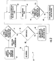
- FIG. 3 is a flowchart diagram 50 summarizing an example embodiment of a control technique used by the drive assembly for protecting the drive components from adverse environmental conditions, such as humidity and moisture.
- the controller 48 receives an indication from the sensor 32 regarding at least the humidity in the area near the drive 30.
- the controller 48 is programmed or otherwise configured to determine whether the humidity level is within a desired or acceptable humidity range.
- the range may have various values or thresholds for different temperature conditions.
- the temperature used by the controller 48 may be an ambient temperature near the drive 30 or at least one temperature of at least one of the drive components.
- the controller 48 determines if the detected humidity level is within the acceptable range.
- the controller 48 in some embodiments is configured to determine the range based only on the humidity indication. In such examples, the controller may have a preset range.
- the controller 48 uses a combination of humidity and temperature indications in other embodiments for determining whether the sensed humidity is in an acceptable range or if the controller 48 should take some action to avoid or at least reduce condensation on the drive 30.
- the temperature indication from the sensor 32 may be such that a lower humidity threshold is appropriate for determining if condensation is likely. Under other temperature conditions a higher humidity reading from the sensor 32 may be acceptable. In such embodiments determining whether the humidity is outside the acceptable range is at least partially based on the temperature information provided by the sensor 32.
- the controller 48 determines whether the drive 30 is currently operating to cause movement of the elevator car 22 or if the drive 30 is idle at 56. When the drive 30 is operating (i.e., not idle) the controller 48 does not do anything in response to the humidity level as shown at 58. Similarly, if the determination at 54 indicates that the humidity level is in the acceptable or desired range, then the controller 48 does not do anything.
- the controller 60 automatically turns on at least a portion of the drive 30.
- the controller initiates a converter d-axis and inverter d-axis control mode of the drive.
- Known field orientation control techniques are used in some embodiments to realize the d-axis control mode.
- Controlling at least the converter and the inverter of the drive 30 in a d-axis control mode allows for flowing reactive power to at least selected components of the drive 30 as shown at 62.
- the controller 48 causes current to flow through at least one of the IGBTs 44 or at least one line reactor 46. The reactive power in such a control mode does not cause the drive 30 to operate the machine 28 but, instead, allows for current flow in a passive mode through passive components, such as the IGBTs 44 and the line reactor 46.
- the current flowing at 62 results in heat generation that is effective to increase a temperature of at least some portions of the drive 30 to prevent moisture build up or condensation on components of the drive that are susceptible to damage or compromised performance if exposed to moisture.
- the resulting heat provides protection against moisture or high humidity conditions for such components without requiring expensive coatings on such components.
- the controller 48 turns on at least one fan 65 ( Figure 2 ) to assist in protecting the drive 30.
- the fan 65 may be a portion of the drive assembly that is used in some conditions to cool portions of the drive 30 or may be a dedicated fan for moving air near the drive to assist in distributing the heat generated by the reactive power current provided in response to the humidity determination at 54.
- the fan 65 may also be effective at removing moisture or drying it if any moisture collects or condensation forms on portions of the drive 30. Operating the fan 65 in this embodiment is an optional feature and the controller 48 is programmed or otherwise configured to determine when fan operation is desired or needed.
- the controller 48 determines if the drive becomes active or should start operating while the reactive power is on at 62. If that occurs, the controller 48 turns off the supply of reactive power and waits until the drive 30 becomes idle again before taking further action for moisture control under humid conditions.
- the drive assembly and control technique of the example embodiment provide control over condensation and moisture exposure for an elevator drive in an economical manner that does not interfere with typical elevator system operation and that can be implemented without requiring redesign of an elevator drive.
Landscapes
- Engineering & Computer Science (AREA)
- Automation & Control Theory (AREA)
- Chemical & Material Sciences (AREA)
- Combustion & Propulsion (AREA)
- Mechanical Engineering (AREA)
- General Engineering & Computer Science (AREA)
- Physics & Mathematics (AREA)
- General Physics & Mathematics (AREA)
- Computer Networks & Wireless Communication (AREA)
- Elevator Control (AREA)
- Inverter Devices (AREA)
Abstract
Description
- Elevator systems typically include a drive assembly that is responsible for the movement of the elevator car. Typical drives include a drive portion having electronics for controlling the power and command signals provided to a motor. Most arrangements include electric motors that cause desired movement of an elevator car responsive to the signals and power provided through the drive.
- The electronic components of elevator drives may be housed in a cabinet or housing within a machine room or inside the hoistway. While the cabinet or housing provides some protection for the drive components, they are still subject to a variety of conditions that may have an adverse effect on the performance or longevity of the components or the drive. For example, humidity and temperature conditions may change in ways that potentially adversely affect at least some of the drive components.
- One approach at protecting drive components has been to use a conformal coating on electrical components to protect them from moisture or chemical exposure. While such coatings are effective they add expense to the drive. Additionally if any of the coated components need testing the coating may have to be removed, which introduces additional expense.
- It is necessary to protect elevator drive components from moisture and it would be beneficial to be able to accomplish that goal without needing a conformal coating.
- An illustrative example method of maintaining an elevator drive includes determining whether a humidity condition near the elevator drive is outside a desired range. When the humidity condition is outside the desired range and the elevator drive is idle, reactive power is provided to at least one component of the elevator drive to increase a temperature of the at least one component without using the elevator drive to operate an associated elevator system.
- In an example method having one or more features of the method of the previous paragraph, providing reactive power to the elevator drive includes providing reactive power on an input and an output of the elevator drive.
- In an example method having one or more features of the method of any of the previous paragraphs, providing reactive power to the elevator drive includes turning on the elevator drive in at least one of a converter d-axis control mode and an inverter d-axis control mode.
- In an example method having one or more features of the method of any of the previous paragraphs, the at least one component comprises IGBTs.
- In an example method having one or more features of the method of any of the previous paragraphs, the at least one component comprises a line reactor.
- An example method having one or more features of the method of any of the previous paragraphs includes turning on a fan to direct airflow near the elevator drive while providing the reactive power to the elevator drive.
- An example method having one or more features of the method of any of the previous paragraphs includes ceasing providing the reactive power to the elevator drive in response to the elevator drive being needed to operate the associated elevator system or the humidity condition changing to be inside the desired range.
- An example method having one or more features of the method of any of the previous paragraphs includes determining a temperature near the elevator drive and determining whether the humidity is outside the desired range is based on the determined temperature.
- In an example method having one or more features of the method of any of the previous paragraphs, the desired range for the determined humidity condition is different for different determined temperatures.
- In an example method having one or more features of the method of any of the previous paragraphs, when the humidity condition is outside the desired range and the elevator drive is running to operate the associated elevator system, the method includes continuing to run the drive.
- An illustrative example embodiment of an elevator drive assembly includes an elevator drive circuit including at least one passive component, a humidity sensor, and a controller that is configured to determine whether a humidity condition detected by the humidity sensor is outside a desired range. The controller will provide reactive power to at the least one passive component of the elevator drive to increase a temperature of the at least one passive component without using the elevator drive to operate an associated elevator system when the humidity condition is outside the desired range and the elevator drive is idle.
- In an example elevator drive assembly having one or more features of the assembly of the previous paragraph, the controller provides reactive power to the elevator drive by providing reactive power on an input and an output of the elevator drive circuit.
- In an example elevator drive assembly having one or more features of the assembly of any of the previous paragraphs, the controller provides reactive power to the elevator drive by turning on the elevator drive in at least one of a converter d-axis control mode and an inverter d-axis control mode.
- In an example elevator drive assembly having one or more features of the assembly of any of the previous paragraphs, the at least one passive component comprises IGBTs.
- In an example elevator drive assembly having one or more features of the assembly of any of the previous paragraphs, the at least one passive component comprises a line reactor.
- An example elevator drive assembly having one or more features of the assembly of any of the previous paragraphs includes a fan situated to direct airflow near the elevator drive and the controller turns on the fan while providing the reactive power to the elevator drive circuit.
- In an example elevator drive assembly having one or more features of the assembly of any of the previous paragraphs, the controller stops providing the reactive power to the elevator drive in response to the elevator drive being needed to operate the associated elevator system or the controller determining that the humidity condition changed to be inside the desired range.
- An example elevator drive assembly having one or more features of the assembly of any of the previous paragraphs includes a temperature sensor that provides an indication of a temperature near the elevator drive circuit and the controller is configured to determine whether the humidity condition is outside the desired range based on the temperature.
- In an example elevator drive assembly having one or more features of the assembly of any of the previous paragraphs, the desired range for the determined humidity condition is different for different determined temperatures.
- In an example elevator drive assembly having one or more features of the assembly of any of the previous paragraphs, the controller is configured to continue to run the drive when the humidity condition is outside the desired range and the elevator drive is running to operate the associated elevator system.
- The various features and advantages of at least one disclosed example embodiment will become apparent to those skilled in the art from the following detailed description. The drawings that accompany the detailed description can be briefly described as follows.
-
Figure 1 schematically illustrates selected portions of an elevator system designed according to an embodiment of this invention. -
Figure 2 diagrammatically illustrates selected features of an example elevator drive assembly designed according to an embodiment of this invention. -
Figure 3 is a flow chart diagram summarizing an example drive control technique designed according to an embodiment of this invention. - Example embodiments of this invention provide control over elevator drive components for protecting the drive components from environmental conditions, such as humidity or moisture without requiring a conformal coating or another treatment applied to the drive or its components.
-
Figure 1 schematically illustrates selected portions of anelevator system 20. Anelevator car 22 andcounterweight 24 are situated for movement in ahoistway 26 in a known manner. Amachine 28 includes a motor for moving theelevator car 22 and a brake for holding theelevator car 22 at a landing where elevator service is needed. Adrive 30 controls operation of themachine 28 in a known manner. One type of traction-based elevator system is illustrated for discussion purposes but embodiments of this invention are useful in a variety of elevator system configurations. - A
sensor 32 is situated near thedrive 30 for sensing at least one environmental condition that may have an impact on at least a portion of thedrive 30. In the illustrated embodiment, thesensor 32 is capable of sensing at least a humidity level in a vicinity of thesensor 32. In some embodiments thesensor 32 also senses temperature. -
Figure 2 schematically illustrates a drive assembly. Thedrive 30 in this example includes a printed circuit board (PCB) 40 that supports drive electronics represented at 42. Thedrive 30 includes insulated gate bipolar transistors (IGBTs) 44 andline reactors 46 for controlling current supply to the motor of themachine 28 in a known manner. - The drive assembly of
Figure 2 includes acontroller 48 that uses information from thesensor 32 to control thedrive 30 in a manner that is useful to reduce or eliminate at least some potentially negative environmental effects on the drive components. Thecontroller 48 comprises at least one computing device, such as a microprocessor. Although schematically represented as a separate component, thecontroller 48 may be realized as a portion of a controller or computing device that is integrated as part of thedrive 30. -
Figure 3 is a flowchart diagram 50 summarizing an example embodiment of a control technique used by the drive assembly for protecting the drive components from adverse environmental conditions, such as humidity and moisture. At 52 thecontroller 48 receives an indication from thesensor 32 regarding at least the humidity in the area near thedrive 30. Thecontroller 48 is programmed or otherwise configured to determine whether the humidity level is within a desired or acceptable humidity range. The range may have various values or thresholds for different temperature conditions. The temperature used by thecontroller 48 may be an ambient temperature near thedrive 30 or at least one temperature of at least one of the drive components. - At 54 the
controller 48 determines if the detected humidity level is within the acceptable range. Thecontroller 48 in some embodiments is configured to determine the range based only on the humidity indication. In such examples, the controller may have a preset range. Thecontroller 48 uses a combination of humidity and temperature indications in other embodiments for determining whether the sensed humidity is in an acceptable range or if thecontroller 48 should take some action to avoid or at least reduce condensation on thedrive 30. For example, the temperature indication from thesensor 32 may be such that a lower humidity threshold is appropriate for determining if condensation is likely. Under other temperature conditions a higher humidity reading from thesensor 32 may be acceptable. In such embodiments determining whether the humidity is outside the acceptable range is at least partially based on the temperature information provided by thesensor 32. - When the humidity level is outside the acceptable range the
controller 48 determines whether thedrive 30 is currently operating to cause movement of theelevator car 22 or if thedrive 30 is idle at 56. When thedrive 30 is operating (i.e., not idle) thecontroller 48 does not do anything in response to the humidity level as shown at 58. Similarly, if the determination at 54 indicates that the humidity level is in the acceptable or desired range, then thecontroller 48 does not do anything. - If the drive is idle at 56 the
controller 60 automatically turns on at least a portion of thedrive 30. In this example the controller initiates a converter d-axis and inverter d-axis control mode of the drive. Known field orientation control techniques are used in some embodiments to realize the d-axis control mode. Controlling at least the converter and the inverter of thedrive 30 in a d-axis control mode allows for flowing reactive power to at least selected components of thedrive 30 as shown at 62. In the illustrated example thecontroller 48 causes current to flow through at least one of theIGBTs 44 or at least oneline reactor 46. The reactive power in such a control mode does not cause thedrive 30 to operate themachine 28 but, instead, allows for current flow in a passive mode through passive components, such as theIGBTs 44 and theline reactor 46. - The current flowing at 62 results in heat generation that is effective to increase a temperature of at least some portions of the
drive 30 to prevent moisture build up or condensation on components of the drive that are susceptible to damage or compromised performance if exposed to moisture. The resulting heat provides protection against moisture or high humidity conditions for such components without requiring expensive coatings on such components. - In the illustrated example, the
controller 48 turns on at least one fan 65 (Figure 2 ) to assist in protecting thedrive 30. Thefan 65 may be a portion of the drive assembly that is used in some conditions to cool portions of thedrive 30 or may be a dedicated fan for moving air near the drive to assist in distributing the heat generated by the reactive power current provided in response to the humidity determination at 54. Thefan 65 may also be effective at removing moisture or drying it if any moisture collects or condensation forms on portions of thedrive 30. Operating thefan 65 in this embodiment is an optional feature and thecontroller 48 is programmed or otherwise configured to determine when fan operation is desired or needed. - At 66 the
controller 48 determines if the humidity level is still outside the acceptable range. That determination is based on sensed temperature and humidity information in some embodiments. If so, thecontroller 48 continues supplying reactive power current to one or more of the components of thedrive 30 to continue generating heat. Once the humidity level is back to an acceptable level, at 68 thecontroller 48 stops the reactive power and turns off thefan 65 if the fan was activated. - Although not specifically illustrated as a step in the
flowchart 50, thecontroller 48 determines if the drive becomes active or should start operating while the reactive power is on at 62. If that occurs, thecontroller 48 turns off the supply of reactive power and waits until thedrive 30 becomes idle again before taking further action for moisture control under humid conditions. - The drive assembly and control technique of the example embodiment provide control over condensation and moisture exposure for an elevator drive in an economical manner that does not interfere with typical elevator system operation and that can be implemented without requiring redesign of an elevator drive.
- The preceding description is exemplary rather than limiting in nature. Variations and modifications to the disclosed examples may become apparent to those skilled in the art that do not necessarily depart from the essence of this invention. The scope of legal protection given to this invention can only be determined by studying the following claims.
Claims (15)
- A method of maintaining an elevator drive, the method comprising:determining whether a humidity condition near the elevator drive is outside a desired range; andwhen the humidity condition is outside the desired range and the elevator drive is idle, providing reactive power to at least one component of the elevator drive to increase a temperature of the at least one component without using the elevator drive to operate an associated elevator system.
- The method of claim 1, wherein providing reactive power to the elevator drive includes providing reactive power on an input and an output of the elevator drive.
- The method of claim 1 or 2, wherein providing reactive power to the elevator drive includes
turning on the elevator drive in at least one of a converter d-axis control mode and an inverter d-axis control mode. - The method of any of claims 1 to 3, wherein the at least one component comprises IGBTs.
- The method of any of claims 1 to 4, wherein the at least one component comprises a line reactor.
- The method of any of claims 1 to 5, comprising
turning on a fan to direct airflow near the elevator drive while providing the reactive power to the elevator drive. - The method of any of claims 1 to 6, comprising ceasing providing the reactive power to the elevator drive in response to the elevator drive being needed to operate the associated elevator system or the humidity condition changing to be inside the desired range.
- The method of any of claims 1 to 7, comprising
determining a temperature near the elevator drive; and
wherein determining whether the humidity is outside the desired range is based on the determined temperature. - The method of claim 8, wherein the desired range for the determined humidity condition is different for different determined temperatures.
- The method of any of claims 1 to 9, wherein when the humidity condition is outside the desired range and the elevator drive is running to operate the associated elevator system, the method includes continuing to run the drive.
- An elevator drive assembly, comprising:an elevator drive circuit including at least one passive component;a humidity sensor; anda controller that is configured to carry out the method of any of claims 1 to 10.
- The assembly of claim 11, wherein the controller provides reactive power to the elevator drive by turning on the elevator drive in at least one of a converter d-axis control mode and an inverter d-axis control mode.
- The assembly of claim 11 or 12, comprising
a fan situated to direct airflow near the elevator drive; and
wherein the controller turns on the fan while providing the reactive power to the elevator drive circuit. - The assembly of any of claims 11 to 13, comprising
a temperature sensor that provides an indication of a temperature near the elevator drive circuit; and
wherein the controller is configured to determine whether the humidity condition is outside the desired range based on the temperature. - The assembly of claim 14, wherein the desired range for the determined humidity condition is different for different determined temperatures.
Applications Claiming Priority (1)
| Application Number | Priority Date | Filing Date | Title |
|---|---|---|---|
| US15/613,615 US10287131B2 (en) | 2017-06-05 | 2017-06-05 | Elevator drive control to protect drive components from moisture |
Publications (2)
| Publication Number | Publication Date |
|---|---|
| EP3412616A1 true EP3412616A1 (en) | 2018-12-12 |
| EP3412616B1 EP3412616B1 (en) | 2022-04-20 |
Family
ID=62244377
Family Applications (1)
| Application Number | Title | Priority Date | Filing Date |
|---|---|---|---|
| EP18173992.1A Active EP3412616B1 (en) | 2017-06-05 | 2018-05-24 | Elevator drive control to protect drive components from moisture |
Country Status (3)
| Country | Link |
|---|---|
| US (1) | US10287131B2 (en) |
| EP (1) | EP3412616B1 (en) |
| CN (1) | CN108975099B (en) |
Families Citing this family (2)
| Publication number | Priority date | Publication date | Assignee | Title |
|---|---|---|---|---|
| EP3368459B1 (en) * | 2015-10-29 | 2019-10-16 | Inventio AG | Drive engine arrangement with sensor-monitored fan for an elevator system |
| CN110456844B (en) * | 2019-07-18 | 2021-06-08 | 日立电梯(中国)有限公司 | Elevator control cabinet anti-condensation equipment, method, device and elevator |
Citations (3)
| Publication number | Priority date | Publication date | Assignee | Title |
|---|---|---|---|---|
| GB2450758A (en) * | 2007-07-06 | 2009-01-07 | Cummins Generator Technologies | Device for reducing moisture in a rotating electrical machine |
| US20130110376A1 (en) * | 2011-11-01 | 2013-05-02 | Ford Global Technologies, Llc | Method and system for engine control |
| JP2016222387A (en) * | 2015-05-28 | 2016-12-28 | 株式会社日立ビルシステム | Elevator diagnosis method |
Family Cites Families (31)
| Publication number | Priority date | Publication date | Assignee | Title |
|---|---|---|---|---|
| US3931454A (en) | 1972-10-17 | 1976-01-06 | Westinghouse Electric Corporation | Printed circuit board and method of preparing it |
| US4195324A (en) * | 1978-07-26 | 1980-03-25 | Allen-Bradley Company | Heating circuit for an electric motor |
| JPH05260764A (en) * | 1992-03-13 | 1993-10-08 | Fuji Electric Co Ltd | Method for preventing inverter apparatus from forming dew condensation |
| JPH062904U (en) * | 1992-06-09 | 1994-01-14 | 石川島播磨重工業株式会社 | Condensation prevention device for electrical equipment |
| KR0167157B1 (en) | 1993-01-21 | 1998-12-01 | 이희종 | Humidity Sensing Control Method of Elevator |
| US5631509A (en) * | 1994-07-27 | 1997-05-20 | General Electric Company | Motor having thermostatically controlled or limited space heater |
| JPH08324912A (en) | 1995-06-05 | 1996-12-10 | Mitsubishi Electric Corp | Elevator machine room protector |
| DE19717032C2 (en) | 1997-04-23 | 2000-04-06 | Telefunken Microelectron | Electronic assembly with means for preventing the influence of moisture |
| JP2006136160A (en) * | 2004-11-08 | 2006-05-25 | Toshiba Elevator Co Ltd | Electric motor system |
| JP2007062905A (en) | 2005-08-30 | 2007-03-15 | Toshiba Elevator Co Ltd | Dew condensation prevention device for car of elevator and elevator |
| JP4949660B2 (en) * | 2005-09-14 | 2012-06-13 | 東芝エレベータ株式会社 | Elevator system |
| JP4479920B2 (en) * | 2006-07-13 | 2010-06-09 | 株式会社デンソー | Electric vehicle control device |
| JP2008104281A (en) * | 2006-10-18 | 2008-05-01 | Toyota Motor Corp | Power supply |
| EP2106380B1 (en) * | 2007-01-11 | 2011-12-28 | Otis Elevator Company | Thermoelectric thermal management system for the energy storage system in a regenerative elevator |
| JP4840821B2 (en) | 2007-04-26 | 2011-12-21 | 株式会社東洋製作所 | Dehumidification system for elevator equipment |
| JP5427107B2 (en) * | 2010-05-20 | 2014-02-26 | 株式会社日立製作所 | Monitoring and diagnosis apparatus and monitoring diagnosis method |
| JP5306289B2 (en) | 2010-06-21 | 2013-10-02 | 株式会社日立製作所 | Elevator control device |
| FI123845B (en) | 2011-08-25 | 2013-11-15 | Kone Corp | Operating unit, elevator and operation of operating an elevator |
| US9518570B2 (en) * | 2012-04-12 | 2016-12-13 | Rockwell Automation Technologies, Inc. | Motor winding heater systems and methods |
| CN103589320B (en) | 2012-08-13 | 2015-08-26 | 深圳微步信息股份有限公司 | For three anti-paint and preparation and application thereof of protecting printed circuit board |
| FI123563B (en) * | 2012-09-04 | 2013-07-15 | Kone Corp | Procedure and system for increasing the capacity of a lift that is not used on a floor level |
| JP5827933B2 (en) * | 2012-09-18 | 2015-12-02 | 東芝三菱電機産業システム株式会社 | Semiconductor power conversion device and humidity management method for semiconductor power conversion device |
| CN104275077B (en) * | 2013-07-02 | 2016-12-28 | 艾默生网络能源有限公司 | A kind of dehydrating unit and dehumanization method and there is the wind energy converter of this dehydrating unit |
| WO2015095582A1 (en) * | 2013-12-18 | 2015-06-25 | Ogin, Inc. | Method and apparatus for dehumidification of generator winding insulation |
| CN104073101A (en) | 2014-06-04 | 2014-10-01 | 乐凯特科技铜陵有限公司 | Three-proofing coating for flexible printed circuit board |
| US10160619B2 (en) | 2014-06-30 | 2018-12-25 | Thyssenkrupp Elevator Corporation | Under car power unit for an elevator system |
| CN204280939U (en) | 2014-12-05 | 2015-04-22 | 陆为民 | A kind of elevator operational monitoring forewarn system |
| CN104961011A (en) | 2015-06-29 | 2015-10-07 | 周志鸿 | Elevator temperature and humidity detection device and system |
| WO2017040253A1 (en) * | 2015-08-28 | 2017-03-09 | James Davison | Self-sanitizing electrical machine |
| KR101755470B1 (en) * | 2015-09-11 | 2017-07-07 | 현대자동차 주식회사 | Totally enclosed motor |
| CN106787660A (en) * | 2017-02-08 | 2017-05-31 | 深圳市海浦蒙特科技有限公司 | Frequency converter and its dehumanization method |
-
2017
- 2017-06-05 US US15/613,615 patent/US10287131B2/en active Active
-
2018
- 2018-05-24 EP EP18173992.1A patent/EP3412616B1/en active Active
- 2018-06-05 CN CN201810569233.1A patent/CN108975099B/en active Active
Patent Citations (3)
| Publication number | Priority date | Publication date | Assignee | Title |
|---|---|---|---|---|
| GB2450758A (en) * | 2007-07-06 | 2009-01-07 | Cummins Generator Technologies | Device for reducing moisture in a rotating electrical machine |
| US20130110376A1 (en) * | 2011-11-01 | 2013-05-02 | Ford Global Technologies, Llc | Method and system for engine control |
| JP2016222387A (en) * | 2015-05-28 | 2016-12-28 | 株式会社日立ビルシステム | Elevator diagnosis method |
Also Published As
| Publication number | Publication date |
|---|---|
| CN108975099B (en) | 2023-10-13 |
| EP3412616B1 (en) | 2022-04-20 |
| US10287131B2 (en) | 2019-05-14 |
| CN108975099A (en) | 2018-12-11 |
| US20180346285A1 (en) | 2018-12-06 |
Similar Documents
| Publication | Publication Date | Title |
|---|---|---|
| JP3213156B2 (en) | Electronics | |
| EP2020739B1 (en) | Electric power conversion system | |
| US20090116189A1 (en) | Cooling System for a Computer Power Supply Unit | |
| CN103901908A (en) | Moistureproof protection device and electronic device having the same | |
| JP5524752B2 (en) | Inverter device | |
| US10287131B2 (en) | Elevator drive control to protect drive components from moisture | |
| JP2018537932A (en) | Motor for fan or ventilator, motor for pump or compressor, method of operating the motor, and ventilation system with one or more motor / ventilators | |
| WO2015186208A1 (en) | Power device | |
| KR102459715B1 (en) | Vacuum pump and control device provided in vacuum pump | |
| CN108474569A (en) | The outdoor unit of air conditioner | |
| JP4799572B2 (en) | Inverter device | |
| CN106102409A (en) | Including the electric component for moistureproof device | |
| CN103365351B (en) | Computer system | |
| CN106155142A (en) | Control method and device applied to converter cabinet, mainboard controller and control system | |
| JP3811166B2 (en) | Electronics | |
| US9250634B2 (en) | Method of controlling a power feed and apparatus | |
| EP3489068B1 (en) | Vehicle power conversion device and rail vehicle | |
| CN111034021B (en) | Current value determination device, control device, electric compressor, current value determination method, and control method | |
| JPH07302136A (en) | Electronics | |
| Kaiser et al. | Noise control on computer and business equipment using speed controlled blowers | |
| JP2018155459A (en) | Server apparatus, server apparatus control method, and program | |
| JP5306289B2 (en) | Elevator control device | |
| CN222468572U (en) | Humidity control device and energy storage equipment | |
| JPH11154038A (en) | Electronic equipment having a cooling fan | |
| CN108370232A (en) | Method for controlling electric fan |
Legal Events
| Date | Code | Title | Description |
|---|---|---|---|
| PUAI | Public reference made under article 153(3) epc to a published international application that has entered the european phase |
Free format text: ORIGINAL CODE: 0009012 |
|
| STAA | Information on the status of an ep patent application or granted ep patent |
Free format text: STATUS: THE APPLICATION HAS BEEN PUBLISHED |
|
| AK | Designated contracting states |
Kind code of ref document: A1 Designated state(s): AL AT BE BG CH CY CZ DE DK EE ES FI FR GB GR HR HU IE IS IT LI LT LU LV MC MK MT NL NO PL PT RO RS SE SI SK SM TR |
|
| AX | Request for extension of the european patent |
Extension state: BA ME |
|
| STAA | Information on the status of an ep patent application or granted ep patent |
Free format text: STATUS: REQUEST FOR EXAMINATION WAS MADE |
|
| 17P | Request for examination filed |
Effective date: 20190605 |
|
| RBV | Designated contracting states (corrected) |
Designated state(s): AL AT BE BG CH CY CZ DE DK EE ES FI FR GB GR HR HU IE IS IT LI LT LU LV MC MK MT NL NO PL PT RO RS SE SI SK SM TR |
|
| STAA | Information on the status of an ep patent application or granted ep patent |
Free format text: STATUS: EXAMINATION IS IN PROGRESS |
|
| 17Q | First examination report despatched |
Effective date: 20200804 |
|
| GRAP | Despatch of communication of intention to grant a patent |
Free format text: ORIGINAL CODE: EPIDOSNIGR1 |
|
| STAA | Information on the status of an ep patent application or granted ep patent |
Free format text: STATUS: GRANT OF PATENT IS INTENDED |
|
| INTG | Intention to grant announced |
Effective date: 20211021 |
|
| GRAS | Grant fee paid |
Free format text: ORIGINAL CODE: EPIDOSNIGR3 |
|
| GRAA | (expected) grant |
Free format text: ORIGINAL CODE: 0009210 |
|
| STAA | Information on the status of an ep patent application or granted ep patent |
Free format text: STATUS: THE PATENT HAS BEEN GRANTED |
|
| AK | Designated contracting states |
Kind code of ref document: B1 Designated state(s): AL AT BE BG CH CY CZ DE DK EE ES FI FR GB GR HR HU IE IS IT LI LT LU LV MC MK MT NL NO PL PT RO RS SE SI SK SM TR |
|
| REG | Reference to a national code |
Ref country code: GB Ref legal event code: FG4D |
|
| REG | Reference to a national code |
Ref country code: CH Ref legal event code: EP |
|
| REG | Reference to a national code |
Ref country code: IE Ref legal event code: FG4D |
|
| REG | Reference to a national code |
Ref country code: DE Ref legal event code: R096 Ref document number: 602018034017 Country of ref document: DE |
|
| REG | Reference to a national code |
Ref country code: AT Ref legal event code: REF Ref document number: 1485031 Country of ref document: AT Kind code of ref document: T Effective date: 20220515 |
|
| REG | Reference to a national code |
Ref country code: LT Ref legal event code: MG9D |
|
| REG | Reference to a national code |
Ref country code: NL Ref legal event code: MP Effective date: 20220420 |
|
| REG | Reference to a national code |
Ref country code: AT Ref legal event code: MK05 Ref document number: 1485031 Country of ref document: AT Kind code of ref document: T Effective date: 20220420 |
|
| PG25 | Lapsed in a contracting state [announced via postgrant information from national office to epo] |
Ref country code: NL Free format text: LAPSE BECAUSE OF FAILURE TO SUBMIT A TRANSLATION OF THE DESCRIPTION OR TO PAY THE FEE WITHIN THE PRESCRIBED TIME-LIMIT Effective date: 20220420 |
|
| PG25 | Lapsed in a contracting state [announced via postgrant information from national office to epo] |
Ref country code: SE Free format text: LAPSE BECAUSE OF FAILURE TO SUBMIT A TRANSLATION OF THE DESCRIPTION OR TO PAY THE FEE WITHIN THE PRESCRIBED TIME-LIMIT Effective date: 20220420 Ref country code: PT Free format text: LAPSE BECAUSE OF FAILURE TO SUBMIT A TRANSLATION OF THE DESCRIPTION OR TO PAY THE FEE WITHIN THE PRESCRIBED TIME-LIMIT Effective date: 20220822 Ref country code: NO Free format text: LAPSE BECAUSE OF FAILURE TO SUBMIT A TRANSLATION OF THE DESCRIPTION OR TO PAY THE FEE WITHIN THE PRESCRIBED TIME-LIMIT Effective date: 20220720 Ref country code: LT Free format text: LAPSE BECAUSE OF FAILURE TO SUBMIT A TRANSLATION OF THE DESCRIPTION OR TO PAY THE FEE WITHIN THE PRESCRIBED TIME-LIMIT Effective date: 20220420 Ref country code: HR Free format text: LAPSE BECAUSE OF FAILURE TO SUBMIT A TRANSLATION OF THE DESCRIPTION OR TO PAY THE FEE WITHIN THE PRESCRIBED TIME-LIMIT Effective date: 20220420 Ref country code: GR Free format text: LAPSE BECAUSE OF FAILURE TO SUBMIT A TRANSLATION OF THE DESCRIPTION OR TO PAY THE FEE WITHIN THE PRESCRIBED TIME-LIMIT Effective date: 20220721 Ref country code: FI Free format text: LAPSE BECAUSE OF FAILURE TO SUBMIT A TRANSLATION OF THE DESCRIPTION OR TO PAY THE FEE WITHIN THE PRESCRIBED TIME-LIMIT Effective date: 20220420 Ref country code: ES Free format text: LAPSE BECAUSE OF FAILURE TO SUBMIT A TRANSLATION OF THE DESCRIPTION OR TO PAY THE FEE WITHIN THE PRESCRIBED TIME-LIMIT Effective date: 20220420 Ref country code: BG Free format text: LAPSE BECAUSE OF FAILURE TO SUBMIT A TRANSLATION OF THE DESCRIPTION OR TO PAY THE FEE WITHIN THE PRESCRIBED TIME-LIMIT Effective date: 20220720 Ref country code: AT Free format text: LAPSE BECAUSE OF FAILURE TO SUBMIT A TRANSLATION OF THE DESCRIPTION OR TO PAY THE FEE WITHIN THE PRESCRIBED TIME-LIMIT Effective date: 20220420 |
|
| PG25 | Lapsed in a contracting state [announced via postgrant information from national office to epo] |
Ref country code: RS Free format text: LAPSE BECAUSE OF FAILURE TO SUBMIT A TRANSLATION OF THE DESCRIPTION OR TO PAY THE FEE WITHIN THE PRESCRIBED TIME-LIMIT Effective date: 20220420 Ref country code: PL Free format text: LAPSE BECAUSE OF FAILURE TO SUBMIT A TRANSLATION OF THE DESCRIPTION OR TO PAY THE FEE WITHIN THE PRESCRIBED TIME-LIMIT Effective date: 20220420 Ref country code: LV Free format text: LAPSE BECAUSE OF FAILURE TO SUBMIT A TRANSLATION OF THE DESCRIPTION OR TO PAY THE FEE WITHIN THE PRESCRIBED TIME-LIMIT Effective date: 20220420 Ref country code: IS Free format text: LAPSE BECAUSE OF FAILURE TO SUBMIT A TRANSLATION OF THE DESCRIPTION OR TO PAY THE FEE WITHIN THE PRESCRIBED TIME-LIMIT Effective date: 20220820 |
|
| REG | Reference to a national code |
Ref country code: CH Ref legal event code: PL |
|
| REG | Reference to a national code |
Ref country code: DE Ref legal event code: R097 Ref document number: 602018034017 Country of ref document: DE |
|
| REG | Reference to a national code |
Ref country code: BE Ref legal event code: MM Effective date: 20220531 |
|
| PG25 | Lapsed in a contracting state [announced via postgrant information from national office to epo] |
Ref country code: SM Free format text: LAPSE BECAUSE OF FAILURE TO SUBMIT A TRANSLATION OF THE DESCRIPTION OR TO PAY THE FEE WITHIN THE PRESCRIBED TIME-LIMIT Effective date: 20220420 Ref country code: SK Free format text: LAPSE BECAUSE OF FAILURE TO SUBMIT A TRANSLATION OF THE DESCRIPTION OR TO PAY THE FEE WITHIN THE PRESCRIBED TIME-LIMIT Effective date: 20220420 Ref country code: RO Free format text: LAPSE BECAUSE OF FAILURE TO SUBMIT A TRANSLATION OF THE DESCRIPTION OR TO PAY THE FEE WITHIN THE PRESCRIBED TIME-LIMIT Effective date: 20220420 Ref country code: MC Free format text: LAPSE BECAUSE OF FAILURE TO SUBMIT A TRANSLATION OF THE DESCRIPTION OR TO PAY THE FEE WITHIN THE PRESCRIBED TIME-LIMIT Effective date: 20220420 Ref country code: LU Free format text: LAPSE BECAUSE OF NON-PAYMENT OF DUE FEES Effective date: 20220524 Ref country code: LI Free format text: LAPSE BECAUSE OF NON-PAYMENT OF DUE FEES Effective date: 20220531 Ref country code: EE Free format text: LAPSE BECAUSE OF FAILURE TO SUBMIT A TRANSLATION OF THE DESCRIPTION OR TO PAY THE FEE WITHIN THE PRESCRIBED TIME-LIMIT Effective date: 20220420 Ref country code: DK Free format text: LAPSE BECAUSE OF FAILURE TO SUBMIT A TRANSLATION OF THE DESCRIPTION OR TO PAY THE FEE WITHIN THE PRESCRIBED TIME-LIMIT Effective date: 20220420 Ref country code: CZ Free format text: LAPSE BECAUSE OF FAILURE TO SUBMIT A TRANSLATION OF THE DESCRIPTION OR TO PAY THE FEE WITHIN THE PRESCRIBED TIME-LIMIT Effective date: 20220420 Ref country code: CH Free format text: LAPSE BECAUSE OF NON-PAYMENT OF DUE FEES Effective date: 20220531 |
|
| PLBE | No opposition filed within time limit |
Free format text: ORIGINAL CODE: 0009261 |
|
| STAA | Information on the status of an ep patent application or granted ep patent |
Free format text: STATUS: NO OPPOSITION FILED WITHIN TIME LIMIT |
|
| 26N | No opposition filed |
Effective date: 20230123 |
|
| GBPC | Gb: european patent ceased through non-payment of renewal fee |
Effective date: 20220720 |
|
| PG25 | Lapsed in a contracting state [announced via postgrant information from national office to epo] |
Ref country code: AL Free format text: LAPSE BECAUSE OF FAILURE TO SUBMIT A TRANSLATION OF THE DESCRIPTION OR TO PAY THE FEE WITHIN THE PRESCRIBED TIME-LIMIT Effective date: 20220420 |
|
| PG25 | Lapsed in a contracting state [announced via postgrant information from national office to epo] |
Ref country code: IE Free format text: LAPSE BECAUSE OF NON-PAYMENT OF DUE FEES Effective date: 20220524 |
|
| PG25 | Lapsed in a contracting state [announced via postgrant information from national office to epo] |
Ref country code: SI Free format text: LAPSE BECAUSE OF FAILURE TO SUBMIT A TRANSLATION OF THE DESCRIPTION OR TO PAY THE FEE WITHIN THE PRESCRIBED TIME-LIMIT Effective date: 20220420 Ref country code: GB Free format text: LAPSE BECAUSE OF NON-PAYMENT OF DUE FEES Effective date: 20220720 Ref country code: BE Free format text: LAPSE BECAUSE OF NON-PAYMENT OF DUE FEES Effective date: 20220531 |
|
| PG25 | Lapsed in a contracting state [announced via postgrant information from national office to epo] |
Ref country code: IT Free format text: LAPSE BECAUSE OF FAILURE TO SUBMIT A TRANSLATION OF THE DESCRIPTION OR TO PAY THE FEE WITHIN THE PRESCRIBED TIME-LIMIT Effective date: 20220420 |
|
| PG25 | Lapsed in a contracting state [announced via postgrant information from national office to epo] |
Ref country code: HU Free format text: LAPSE BECAUSE OF FAILURE TO SUBMIT A TRANSLATION OF THE DESCRIPTION OR TO PAY THE FEE WITHIN THE PRESCRIBED TIME-LIMIT; INVALID AB INITIO Effective date: 20180524 |
|
| PG25 | Lapsed in a contracting state [announced via postgrant information from national office to epo] |
Ref country code: MK Free format text: LAPSE BECAUSE OF FAILURE TO SUBMIT A TRANSLATION OF THE DESCRIPTION OR TO PAY THE FEE WITHIN THE PRESCRIBED TIME-LIMIT Effective date: 20220420 Ref country code: CY Free format text: LAPSE BECAUSE OF FAILURE TO SUBMIT A TRANSLATION OF THE DESCRIPTION OR TO PAY THE FEE WITHIN THE PRESCRIBED TIME-LIMIT Effective date: 20220420 |
|
| PG25 | Lapsed in a contracting state [announced via postgrant information from national office to epo] |
Ref country code: TR Free format text: LAPSE BECAUSE OF FAILURE TO SUBMIT A TRANSLATION OF THE DESCRIPTION OR TO PAY THE FEE WITHIN THE PRESCRIBED TIME-LIMIT Effective date: 20220420 |
|
| PG25 | Lapsed in a contracting state [announced via postgrant information from national office to epo] |
Ref country code: MT Free format text: LAPSE BECAUSE OF FAILURE TO SUBMIT A TRANSLATION OF THE DESCRIPTION OR TO PAY THE FEE WITHIN THE PRESCRIBED TIME-LIMIT Effective date: 20220420 |
|
| PG25 | Lapsed in a contracting state [announced via postgrant information from national office to epo] |
Ref country code: BG Free format text: LAPSE BECAUSE OF FAILURE TO SUBMIT A TRANSLATION OF THE DESCRIPTION OR TO PAY THE FEE WITHIN THE PRESCRIBED TIME-LIMIT Effective date: 20220420 |
|
| PG25 | Lapsed in a contracting state [announced via postgrant information from national office to epo] |
Ref country code: BG Free format text: LAPSE BECAUSE OF FAILURE TO SUBMIT A TRANSLATION OF THE DESCRIPTION OR TO PAY THE FEE WITHIN THE PRESCRIBED TIME-LIMIT Effective date: 20220420 |
|
| PGFP | Annual fee paid to national office [announced via postgrant information from national office to epo] |
Ref country code: DE Payment date: 20250423 Year of fee payment: 8 |
|
| PGFP | Annual fee paid to national office [announced via postgrant information from national office to epo] |
Ref country code: FR Payment date: 20250424 Year of fee payment: 8 |