EP3412578A1 - Combined mode controller and display control unit - Google Patents
Combined mode controller and display control unit Download PDFInfo
- Publication number
- EP3412578A1 EP3412578A1 EP18171681.2A EP18171681A EP3412578A1 EP 3412578 A1 EP3412578 A1 EP 3412578A1 EP 18171681 A EP18171681 A EP 18171681A EP 3412578 A1 EP3412578 A1 EP 3412578A1
- Authority
- EP
- European Patent Office
- Prior art keywords
- inputs
- primary flight
- display
- control
- flight display
- Prior art date
- Legal status (The legal status is an assumption and is not a legal conclusion. Google has not performed a legal analysis and makes no representation as to the accuracy of the status listed.)
- Granted
Links
Images




Classifications
-
- B—PERFORMING OPERATIONS; TRANSPORTING
- B64—AIRCRAFT; AVIATION; COSMONAUTICS
- B64D—EQUIPMENT FOR FITTING IN OR TO AIRCRAFT; FLIGHT SUITS; PARACHUTES; ARRANGEMENT OR MOUNTING OF POWER PLANTS OR PROPULSION TRANSMISSIONS IN AIRCRAFT
- B64D43/00—Arrangements or adaptations of instruments
-
- G—PHYSICS
- G01—MEASURING; TESTING
- G01C—MEASURING DISTANCES, LEVELS OR BEARINGS; SURVEYING; NAVIGATION; GYROSCOPIC INSTRUMENTS; PHOTOGRAMMETRY OR VIDEOGRAMMETRY
- G01C23/00—Combined instruments indicating more than one navigational value, e.g. for aircraft; Combined measuring devices for measuring two or more variables of movement, e.g. distance, speed or acceleration
-
- G—PHYSICS
- G08—SIGNALLING
- G08G—TRAFFIC CONTROL SYSTEMS
- G08G5/00—Traffic control systems for aircraft
- G08G5/20—Arrangements for acquiring, generating, sharing or displaying traffic information
- G08G5/21—Arrangements for acquiring, generating, sharing or displaying traffic information located onboard the aircraft
Definitions
- Aircraft cockpits commonly include one or more primary flight displays (“PFD”) and one or more multi-function displays (“MFD”).
- the PFD may be configured to display situational flight information. This information may include, for example, speed, attitude, vertical rate, altitude, flight progress, GPS location, plotted versus actual course, etc.
- the MFD may be configured to display navigation route, map, weather radar, ground proximity warning system information, traffic collision avoidance information, and more.
- PFD primary flight displays
- MFD multi-function displays
- the PFD and MFD controls may generally be incorporated directly into the frame surrounding the PFD or MFD, respectively, or they may be located in a separate control unit placed elsewhere in the cockpit within reach of the corresponding pilot.
- the only location in a cockpit that is easily accessible to both pilots is the center stack. Given that all of the flight controls must be within reach of both pilots, space on the center stack is limited.
- Aircraft may also include a mode control panel ("MCP").
- MCP mode control panel
- the MCP includes controls to input automated flight behavior.
- the MCP may be used to enter instructions for the aircraft to hold a specific altitude, speed, or heading, to change altitude or speed at a specific rate; or to input a new heading, etc. Accordingly, the flight controls included on the MCP should be within reach of both pilots, and therefore, the MCP should be located on the center stack.
- this disclosure provides a single controller unit that combines the input controls of an MCP with the input controls of at least one PFD.
- the disclosed combined controller unit may be used on any aircraft, including fixed wing aircraft as well as rotorcraft.
- the combined controller not only saves space but saves weight and enables the cockpit to include PFD controls on the crowded center stack.
- the combination of control units allows for the elimination of some inputs, as some of the inputs on the combined unit may perform multiple functions.
- the combined unit enables some of the inputs to act as back-up inputs for other functions in the event the main inputs fail.
- the PFD controls may serve as backup controls for the MFD.
- Cockpit 101 includes a first primary flight display 103 and a second primary flight display 105 for the display of flight information to a first pilot and a second pilot, respectively.
- the flight information may include, but is not limited to, airspeed, altitude, attitude, heading, course deviation indicator, and map.
- the screens of first primary flight display 103 and second primary flight display 105 may be LCD, LED, or any other suitable type of display screen.
- the first primary flight display 103 may include a plurality of inputs 107 located on the frame thereof.
- second primary flight display 105 may include a plurality of inputs 109 located on the frame thereof.
- These inputs 107, 109 may be soft keys or hard keys for the control of first and second primary flight displays 103, 105, respectively.
- first multi-function display 111 and second multi-function display 113 In between first primary flight display 103 and second primary flight display 105 are first multi-function display 111 and second multi-function display 113.
- First and second multi-function displays 111, 113 may display navigation route, map, weather radar, ground proximity warning system information, traffic collision avoidance information, and more to the first and second pilot, respectively.
- First multi-function display 111 may include a plurality of inputs 115 in the frame thereof.
- second multi-function display 113 may include a plurality of inputs 117 in the frame thereof.
- These inputs 115, 117 may be soft keys or hard keys for the control of first and second multi-function displays 111, 113.
- first multi-function control unit 121 Located on a center stack 119, between the pilots, is a first multi-function control unit 121. Adjacent to first multi-function control unit 121 is a second multi-function control unit 123. In the embodiment shown in FIG. 1 , both first and second multi-function control units 121, 123 are customizable touch screens configured for the control of first and second multi-function displays 111, 113, respectively. However, first and second multi-function control units 121, 123 may utilize buttons, bezels, dials, joysticks, or any other type of physical inputs, rather than, or in addition to, touch screens. Below first and second multi-function control units 121, 123 is a combined controller 125.
- Combined controller 125 is used to control first primary flight display 103, second primary flight display 105, and to control automated flight behavior. Automated flight behavior may include, but is not limited to, holding a specific altitude, speed, or heading, and changing altitude or speed at a specific rate. As shown in FIGS. 2-5 , combined controller 125 includes a panel 127 having a face 129 and an opposite back 131. Back 131 is configured to attach to a case 133. Case 133 is configured to house and protect the electronic components (not shown) of combined controller 125. On face 129 of panel 127 there are a plurality of first primary flight display inputs 135.
- Plurality of first primary flight display inputs 135 are configured to receive physical inputs from a pilot for the control of first primary flight display 103. Also on face 129 of panel 127 there are a plurality of second primary flight display inputs 137. Plurality of second primary flight display inputs 137 are configured to receive physical inputs from a pilot for the control of second primary flight display 105. Also on face 129 of panel 127 there are a plurality of flight control inputs 139. Plurality of flight control inputs 139 are configured to receive physical inputs from the pilots for the control of automated flight behavior. Any of inputs 135, 137, 139 may be soft keys or hard keys. In addition, while the inputs 135, 137, 139 shown in FIGS. 1-5 are disclosed as physical buttons and dials, it is within the scope of this disclosure to replace some or all of the inputs with touch screen inputs.
- combined controller 125 should be constructed from lightweight materials, such as, aluminum, fiber composites, and high-performance plastics. In addition, combined controller 125 should be made as small as possible while still maintaining ease of use without increasing the risk of accidentally activating inputs adjacent to the intended input. As such, combined controller 125 has a preferred maximum width of 14.25 inches and a preferred maximum height of 3.70 inches. It is also preferred that combined controller 125 be configured as a line replaceable unit, and therefore, combined controller 125 should be entirely self-contained and be easily installed and removed from center stack 119. To aid in the quick installation/removal, combined controller 125 includes four pawl latches 141 configured to engage center stack 119. Pawl latches 141 are engaged with a tool, e.g., a hex wrench or a screw driver, via openings 143 in face 129.
- a tool e.g., a hex wrench or a screw driver
- Cockpit 201 is similar to cockpit 101. As such, similar numbering will be used for similar components.
- Cockpit 201 includes a first primary flight display 203 and a second primary flight display 205 for the display of flight information to a first pilot and a second pilot, respectively.
- first primary flight display 203 and second primary flight display 205 are first multi-function display 211 and second multi-function display 213.
- Adjacent to first multi-function control unit 221 is a second multi-function control unit 223.
- First and second multi-function control units 221, 223 are configured for the control of first and second multi-function displays 211, 213, respectively.
- a combined controller 225 below first and second multi-function control units 221, 223 is a combined controller 225.
- Combined controller 225 is used to control first primary flight display 203, second primary flight display 205, and to control automated flight behavior.
- combined controller 225 includes a panel 227 having a face 229 and an opposite back 231.
- Back 231 is configured to attach to a case 233.
- Case 233 is configured to house and protect the electronic components (not shown) of combined controller 225.
- On face 229 of panel 227 there are a plurality of first primary flight display inputs 235.
- Plurality of first primary flight display inputs 235 are configured to receive physical inputs from a pilot for the control of first primary flight display 203.
- second primary flight display inputs 237 are also on face 229 of panel 227.
- Plurality of second primary flight display inputs 237 are configured to receive physical inputs from a pilot for the control of second primary flight display 205.
- Combined controller 225 also includes four pawl latches 241 configured to engage center stack 219. Pawl latches 241 are engaged with a tool via openings 243 in face 229.
- combined controller 325 includes a panel 327 with a face 329. Face 329 includes a plurality of first primary flight display inputs 335, a plurality of second primary flight display inputs 337, and a plurality of flight control inputs 339. However, unlike combined controllers 125, 225, combined controller 325 includes at least one shared input 345 that is shared between plurality of first primary flight display inputs 335 and plurality of second primary flight display inputs 337.
- Combined controller 425 includes a panel 427 with a face 429. Face 429 includes a plurality of first primary flight display inputs 435, a plurality of second primary flight display inputs 437, and a plurality of flight control inputs 439.
- R Rl +k * (Ru-Rl), wherein k is a variable ranging from 1 percent to 100 percent with a 1 percent increment, i.e., k is 1 percent, 2 percent, 3 percent, 4 percent, 5 percent,...50 percent, 51 percent, 52 percent,..., 95 percent, 96 percent, 95 percent, 98 percent, 99 percent, or 100 percent.
- R Rl +k * (Ru-Rl)
- k is a variable ranging from 1 percent to 100 percent with a 1 percent increment, i.e., k is 1 percent, 2 percent, 3 percent, 4 percent, 5 percent,...50 percent, 51 percent, 52 percent,..., 95 percent, 96 percent, 95 percent, 98 percent, 99 percent, or 100 percent.
- any numerical range defined by two R numbers as defined in the above is also specifically disclosed.
Landscapes
- Engineering & Computer Science (AREA)
- Aviation & Aerospace Engineering (AREA)
- Physics & Mathematics (AREA)
- General Physics & Mathematics (AREA)
- Radar, Positioning & Navigation (AREA)
- Remote Sensing (AREA)
- Traffic Control Systems (AREA)
Abstract
Description
- Aircraft cockpits commonly include one or more primary flight displays ("PFD") and one or more multi-function displays ("MFD"). The PFD may be configured to display situational flight information. This information may include, for example, speed, attitude, vertical rate, altitude, flight progress, GPS location, plotted versus actual course, etc. The MFD may be configured to display navigation route, map, weather radar, ground proximity warning system information, traffic collision avoidance information, and more. In multi-pilot aircraft, it is common for each pilot to have their own PFD and MFD. It is important that each pilot has the ability to control their own displays. As such, the PFD and MFD controls may generally be incorporated directly into the frame surrounding the PFD or MFD, respectively, or they may be located in a separate control unit placed elsewhere in the cockpit within reach of the corresponding pilot. However, depending on workflow within the crew, it may occasionally be desirable for one pilot to adjust the other pilot's displays. As such, it may be desirable for the controls for all of the displays to be within reach of both pilots. The only location in a cockpit that is easily accessible to both pilots is the center stack. Given that all of the flight controls must be within reach of both pilots, space on the center stack is limited.
- Aircraft may also include a mode control panel ("MCP"). The MCP includes controls to input automated flight behavior. For example, the MCP may be used to enter instructions for the aircraft to hold a specific altitude, speed, or heading, to change altitude or speed at a specific rate; or to input a new heading, etc. Accordingly, the flight controls included on the MCP should be within reach of both pilots, and therefore, the MCP should be located on the center stack.
-
-
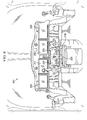
FIG. 1 is an illustration of a cockpit including a combined controller according to this disclosure. -
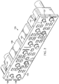
FIG. 2 is an oblique view of the combined controller ofFIG. 1 . -
FIG. 3 is a front view of the combined controller ofFIGS. 1 and2 . -
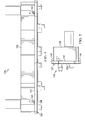
FIG. 4 is a top view of the combined controller ofFIGS. 1-3 . -
FIG. 5 is a right-side view of the combined controller ofFIGS 1-4 . -
FIG. 6 is an illustration of a cockpit including another embodiment of a combined controller according to this disclosure. -
FIG. 7 is an oblique view of the combined controller ofFIG. 6 . -
FIG. 8 is a front view of the combined controller ofFIG. 6 and7 . -
FIG. 9 is a bottom view of the combined controller ofFIGS. 6-8 . -
FIG. 10 is a right-side view of the combined controller ofFIGS. 6-9 . -
FIG. 11 is a front view of the combined controller ofFIGS. 6-10 . -
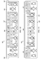
FIG. 12 is a front view of another embodiment of a combined controller according to this disclosure. -
FIG. 13 is a front view of another embodiment of a combined controller according to this disclosure. - In this disclosure, reference may be made to the spatial relationships between various components and to the spatial orientation of various aspects of components as the devices are depicted in the attached drawings. However, as will be recognized by those skilled in the art after a complete reading of this disclosure, the devices, members, apparatuses, etc. described herein may be positioned in any desired orientation. Thus, the use of terms such as "above," "below," "upper," "lower," or other like terms to describe a spatial relationship between various components or to describe the spatial orientation of aspects of such components should be understood to describe a relative relationship between the components or a spatial orientation of aspects of such components, respectively, as the device described herein may be oriented in any desired direction.
- In furtherance of the goals of efficient controller design and weight savings, this disclosure provides a single controller unit that combines the input controls of an MCP with the input controls of at least one PFD. The disclosed combined controller unit may be used on any aircraft, including fixed wing aircraft as well as rotorcraft. The combined controller not only saves space but saves weight and enables the cockpit to include PFD controls on the crowded center stack. Moreover, the combination of control units allows for the elimination of some inputs, as some of the inputs on the combined unit may perform multiple functions. In addition, the combined unit enables some of the inputs to act as back-up inputs for other functions in the event the main inputs fail. For example, the PFD controls may serve as backup controls for the MFD.
- Referring to
FIG. 1 , acockpit 101 of a rotorcraft is illustrated.Cockpit 101 includes a firstprimary flight display 103 and a secondprimary flight display 105 for the display of flight information to a first pilot and a second pilot, respectively. The flight information may include, but is not limited to, airspeed, altitude, attitude, heading, course deviation indicator, and map. The screens of firstprimary flight display 103 and secondprimary flight display 105 may be LCD, LED, or any other suitable type of display screen. The firstprimary flight display 103 may include a plurality ofinputs 107 located on the frame thereof. Similarly, secondprimary flight display 105 may include a plurality ofinputs 109 located on the frame thereof. Theseinputs primary flight display 103 and secondprimary flight display 105 are firstmulti-function display 111 and secondmulti-function display 113. First and second multi-function displays 111, 113 may display navigation route, map, weather radar, ground proximity warning system information, traffic collision avoidance information, and more to the first and second pilot, respectively. Firstmulti-function display 111 may include a plurality ofinputs 115 in the frame thereof. Similarly, secondmulti-function display 113 may include a plurality ofinputs 117 in the frame thereof. Theseinputs center stack 119, between the pilots, is a firstmulti-function control unit 121. Adjacent to firstmulti-function control unit 121 is a secondmulti-function control unit 123. In the embodiment shown inFIG. 1 , both first and secondmulti-function control units multi-function control units multi-function control units controller 125. Combinedcontroller 125 is used to control firstprimary flight display 103, secondprimary flight display 105, and to control automated flight behavior. Automated flight behavior may include, but is not limited to, holding a specific altitude, speed, or heading, and changing altitude or speed at a specific rate. As shown inFIGS. 2-5 , combinedcontroller 125 includes apanel 127 having aface 129 and anopposite back 131.Back 131 is configured to attach to acase 133.Case 133 is configured to house and protect the electronic components (not shown) of combinedcontroller 125. Onface 129 ofpanel 127 there are a plurality of first primaryflight display inputs 135. Plurality of first primaryflight display inputs 135 are configured to receive physical inputs from a pilot for the control of firstprimary flight display 103. Also onface 129 ofpanel 127 there are a plurality of second primaryflight display inputs 137. Plurality of second primaryflight display inputs 137 are configured to receive physical inputs from a pilot for the control of secondprimary flight display 105. Also onface 129 ofpanel 127 there are a plurality offlight control inputs 139. Plurality offlight control inputs 139 are configured to receive physical inputs from the pilots for the control of automated flight behavior. Any ofinputs inputs FIGS. 1-5 are disclosed as physical buttons and dials, it is within the scope of this disclosure to replace some or all of the inputs with touch screen inputs. - As part of the motivation behind combined
controller 125 is to save weight, combinedcontroller 125 should be constructed from lightweight materials, such as, aluminum, fiber composites, and high-performance plastics. In addition, combinedcontroller 125 should be made as small as possible while still maintaining ease of use without increasing the risk of accidentally activating inputs adjacent to the intended input. As such, combinedcontroller 125 has a preferred maximum width of 14.25 inches and a preferred maximum height of 3.70 inches. It is also preferred that combinedcontroller 125 be configured as a line replaceable unit, and therefore, combinedcontroller 125 should be entirely self-contained and be easily installed and removed fromcenter stack 119. To aid in the quick installation/removal, combinedcontroller 125 includes four pawl latches 141 configured to engagecenter stack 119. Pawl latches 141 are engaged with a tool, e.g., a hex wrench or a screw driver, viaopenings 143 inface 129. - Referring to
FIG. 6 , acockpit 201 of a rotorcraft is illustrated.Cockpit 201 is similar tocockpit 101. As such, similar numbering will be used for similar components.Cockpit 201 includes a firstprimary flight display 203 and a secondprimary flight display 205 for the display of flight information to a first pilot and a second pilot, respectively. In between firstprimary flight display 203 and secondprimary flight display 205 are firstmulti-function display 211 and secondmulti-function display 213. Located on acenter stack 219, between the pilots, is a firstmulti-function control unit 221. Adjacent to firstmulti-function control unit 221 is a secondmulti-function control unit 223. First and secondmulti-function control units multi-function displays multi-function control units controller 225. Combinedcontroller 225 is used to control firstprimary flight display 203, secondprimary flight display 205, and to control automated flight behavior. - As shown in
FIGS. 7-11 , combinedcontroller 225 includes apanel 227 having aface 229 and anopposite back 231. Back 231 is configured to attach to acase 233.Case 233 is configured to house and protect the electronic components (not shown) of combinedcontroller 225. Onface 229 ofpanel 227 there are a plurality of first primaryflight display inputs 235. Plurality of first primaryflight display inputs 235 are configured to receive physical inputs from a pilot for the control of firstprimary flight display 203. Also onface 229 ofpanel 227 there are a plurality of second primaryflight display inputs 237. Plurality of second primaryflight display inputs 237 are configured to receive physical inputs from a pilot for the control of secondprimary flight display 205. Also onface 229 ofpanel 227 there are a plurality offlight control inputs 239. Plurality offlight control inputs 239 are configured to receive physical inputs from the pilots for the control of automated flight behavior. Combinedcontroller 225 also includes four pawl latches 241 configured to engagecenter stack 219. Pawl latches 241 are engaged with a tool viaopenings 243 inface 229. - Referring to
FIG. 12 , another embodiment of a combinedcontroller 325 is illustrated. Similar to combinedcontrollers controller 325 includes apanel 327 with aface 329. Face 329 includes a plurality of first primaryflight display inputs 335, a plurality of second primaryflight display inputs 337, and a plurality offlight control inputs 339. However, unlike combinedcontrollers controller 325 includes at least one sharedinput 345 that is shared between plurality of first primaryflight display inputs 335 and plurality of second primaryflight display inputs 337. - Referring to
FIG. 13 , another embodiment of a combinedcontroller 425 is illustrated. Combinedcontroller 425 includes apanel 427 with aface 429. Face 429 includes a plurality of first primaryflight display inputs 435, a plurality of second primaryflight display inputs 437, and a plurality offlight control inputs 439. - At least one embodiment is disclosed, and variations, combinations, and/or modifications of the embodiment(s) and/or features of the embodiment(s) made by a person having ordinary skill in the art are within the scope of the disclosure. Alternative embodiments that result from combining, integrating, and/or omitting features of the embodiment(s) are also within the scope of the disclosure. Where numerical ranges or limitations are expressly stated, such express ranges or limitations should be understood to include iterative ranges or limitations of like magnitude falling within the expressly stated ranges or limitations (e.g., from about 1 to about 10 includes, 2, 3, 4, etc.; greater than 0.10 includes 0.11, 0.12, 0.13, etc.). For example, whenever a numerical range with a lower limit, Rl, and an upper limit, Ru, is disclosed, any number falling within the range is specifically disclosed. In particular, the following numbers within the range are specifically disclosed: R=Rl +k * (Ru-Rl), wherein k is a variable ranging from 1 percent to 100 percent with a 1 percent increment, i.e., k is 1 percent, 2 percent, 3 percent, 4 percent, 5 percent,...50 percent, 51 percent, 52 percent,..., 95 percent, 96 percent, 95 percent, 98 percent, 99 percent, or 100 percent. Moreover, any numerical range defined by two R numbers as defined in the above is also specifically disclosed. Use of the term "optionally" with respect to any element of a claim means that the element is required, or alternatively, the element is not required, both alternatives being within the scope of the claim. Use of broader terms such as comprises, includes, and having should be understood to provide support for narrower terms such as consisting of, consisting essentially of, and comprised substantially of. Accordingly, the scope of protection is not limited by the description set out above but is defined by the claims that follow, that scope including all equivalents of the subject matter of the claims. Each and every claim is incorporated as further disclosure into the specification and the claims are embodiment(s) of the present invention. Also, the phrases "at least one of A, B, and C" and "A and/or B and/or C" should each be interpreted to include only A, only B, only C, or any combination of A, B, and C.
Claims (14)
- A control unit, comprising:a panel having a face and an opposite back;a case attached to the back of the panel;a plurality of first primary flight display inputs on the face of the panel, the plurality of first primary flight display inputs being configured to receive physical inputs for the control of a first primary flight display;a plurality of second primary flight display inputs on the face of the panel, the plurality of second primary flight display inputs being configured to receive physical inputs for the control of a second primary flight display; anda plurality of flight control inputs on the face of the panel, the plurality of flight control inputs being configured to receive physical inputs for the control of automated flight behavior.
- The control unit of claim 1, wherein at least one of each of the plurality of first primary flight display inputs, the plurality of second primary flight display inputs, and the plurality of flight control inputs comprise soft keys.
- The control unit of claim 2, wherein at least one of each of the plurality of first primary flight display inputs, the plurality of second primary flight display inputs, and the plurality of flight control inputs comprise hard keys.
- The control unit of claim 3, wherein at least one of the plurality of first primary flight display inputs is configured to control a first multi-function display.
- The control unit of claim 4, wherein at least one of the plurality of second primary flight display inputs is configured to control a second multi-function display, and optionally or preferably, wherein the panel has a total area of less than fifty-three square inches.
- An aircraft cockpit, comprising:a first primary flight display;a second primary flight display; anda control unit, comprising:a panel having a face and an opposite back;a case attached to the back of the panel;a plurality of first primary flight display inputs on the face of the panel, the plurality of first primary flight display inputs being configured to receive physical inputs for the control of the first primary flight display;a plurality of second primary flight display inputs on the face of the panel, the plurality of second primary flight display inputs being configured to receive physical inputs for the control of the second primary flight display; anda plurality of flight control inputs on the face of the panel, the plurality of flight control inputs being configured to receive physical inputs for the control of automated flight behavior.
- The aircraft cockpit of claim 6, further comprising:a first multi-function display;a first multi-function control unit including a plurality of inputs configured to control the first multi-function display;a second multi-function display; anda second multi-function control unit including a plurality of inputs configured to control the second multi-function display.
- A rotorcraft, comprising:a fuselage;a rotor; anda cockpit disposed within the fuselage, comprising:a first primary flight display;a second primary flight display; anda control unit, comprising:a panel having a face and an opposite back;a case attached to the back of the panel;a plurality of first primary flight display inputs on the face of the panel, the plurality of first primary flight display inputs being configured to receive physical inputs for the control of the first primary flight display;a plurality of second primary flight display inputs on the face of the panel, the plurality of second primary flight display inputs being configured to receive physical inputs for the control of the second primary flight display; anda plurality of flight control inputs on the face of the panel, the plurality of flight control inputs being configured to receive physical inputs for the control of automated flight behavior.
- The rotorcraft of claim 8, the cockpit further comprising:a first multi-function display;a first multi-function control unit including a plurality of inputs configured to control the first multi-function display;a second multi-function display; anda second multi-function control unit including a plurality of inputs configured to control the second multi-function display.
- The aircraft cockpit of claim 7, or the rotorcraft of claim 9, wherein at least one the plurality of first primary flight display inputs is configured to back-up the first multi-function control unit.
- The aircraft cockpit or rotorcraft of claim 10, wherein at least one the plurality of second primary flight display inputs is configured to back-up the second multi-function control unit.
- The aircraft cockpit or rotorcraft of claim 11, wherein at least one of the plurality of inputs on the first multi-function control unit is configured to back-up at least one of the plurality of first primary flight display inputs.
- The aircraft cockpit or rotorcraft of claim 12, wherein at least one of the plurality of inputs on the second multi-function control unit is configured to back-up at least one of the plurality of second primary flight display inputs.
- The aircraft cockpit or rotorcraft of claim 13, wherein at least one of the plurality of first primary flight display inputs, the plurality of second primary flight display inputs, and the plurality of flight control inputs comprises a soft key.
Applications Claiming Priority (1)
| Application Number | Priority Date | Filing Date | Title |
|---|---|---|---|
| US15/617,804 US10173785B2 (en) | 2017-06-08 | 2017-06-08 | Combined mode controller and display control unit |
Publications (2)
| Publication Number | Publication Date |
|---|---|
| EP3412578A1 true EP3412578A1 (en) | 2018-12-12 |
| EP3412578B1 EP3412578B1 (en) | 2021-03-24 |
Family
ID=62152377
Family Applications (1)
| Application Number | Title | Priority Date | Filing Date |
|---|---|---|---|
| EP18171681.2A Active EP3412578B1 (en) | 2017-06-08 | 2018-05-10 | Combined mode controller and display control unit |
Country Status (2)
| Country | Link |
|---|---|
| US (1) | US10173785B2 (en) |
| EP (1) | EP3412578B1 (en) |
Cited By (1)
| Publication number | Priority date | Publication date | Assignee | Title |
|---|---|---|---|---|
| US20210039806A1 (en) * | 2019-08-06 | 2021-02-11 | Gulfstream Aerospace Corporation | Flight guidance panels with joystick controls |
Families Citing this family (2)
| Publication number | Priority date | Publication date | Assignee | Title |
|---|---|---|---|---|
| US11186384B2 (en) | 2019-09-19 | 2021-11-30 | Lockheed Martin Corporation | Adaptive flight display for autonomous aircraft operations |
| US12482614B2 (en) | 2023-04-15 | 2025-11-25 | Textron Innovations Inc. | Flip guard safety systems for aircraft switches |
Citations (4)
| Publication number | Priority date | Publication date | Assignee | Title |
|---|---|---|---|---|
| WO2008036063A2 (en) * | 2005-06-02 | 2008-03-27 | L-3 Communications Avionics Systems, Inc. | Aircraft avionic system having a pilot user interface with context dependent input devices |
| EP2544163A2 (en) * | 2011-07-08 | 2013-01-09 | General Electric Company | A simplified user interface for an aircraft |
| US20140267051A1 (en) * | 2013-03-14 | 2014-09-18 | Garmin International, Inc. | Hybrid aviation user interface |
| US20160123763A1 (en) * | 2014-05-19 | 2016-05-05 | Gulfstream Aerospace Corporation | Methods and systems for displaying flight information |
Family Cites Families (1)
| Publication number | Priority date | Publication date | Assignee | Title |
|---|---|---|---|---|
| US8886372B2 (en) * | 2012-09-07 | 2014-11-11 | The Boeing Company | Flight deck touch-sensitive hardware controls |
-
2017
- 2017-06-08 US US15/617,804 patent/US10173785B2/en active Active
-
2018
- 2018-05-10 EP EP18171681.2A patent/EP3412578B1/en active Active
Patent Citations (4)
| Publication number | Priority date | Publication date | Assignee | Title |
|---|---|---|---|---|
| WO2008036063A2 (en) * | 2005-06-02 | 2008-03-27 | L-3 Communications Avionics Systems, Inc. | Aircraft avionic system having a pilot user interface with context dependent input devices |
| EP2544163A2 (en) * | 2011-07-08 | 2013-01-09 | General Electric Company | A simplified user interface for an aircraft |
| US20140267051A1 (en) * | 2013-03-14 | 2014-09-18 | Garmin International, Inc. | Hybrid aviation user interface |
| US20160123763A1 (en) * | 2014-05-19 | 2016-05-05 | Gulfstream Aerospace Corporation | Methods and systems for displaying flight information |
Cited By (4)
| Publication number | Priority date | Publication date | Assignee | Title |
|---|---|---|---|---|
| US20210039806A1 (en) * | 2019-08-06 | 2021-02-11 | Gulfstream Aerospace Corporation | Flight guidance panels with joystick controls |
| US11649066B2 (en) * | 2019-08-06 | 2023-05-16 | Gulfstream Aerospace Corporation | Flight guidance panels with joystick controls |
| US20230242272A1 (en) * | 2019-08-06 | 2023-08-03 | Gulfstream Aerospace Corporation | Flight guidance panels with joystick controls |
| US11993393B2 (en) * | 2019-08-06 | 2024-05-28 | Gulfstream Aerospace Corporation | Flight guidance panels with joystick controls |
Also Published As
| Publication number | Publication date |
|---|---|
| US20180354645A1 (en) | 2018-12-13 |
| EP3412578B1 (en) | 2021-03-24 |
| US10173785B2 (en) | 2019-01-08 |
Similar Documents
| Publication | Publication Date | Title |
|---|---|---|
| US8354943B2 (en) | Display device for an aircraft for displaying a piloting symbology dedicated to obstacle avoidance | |
| US9567098B2 (en) | Display system for an aircraft and associated method | |
| US9530322B2 (en) | Contextual aid to flight management | |
| JP2009542503A (en) | System and method using multi-view display | |
| EP3412578B1 (en) | Combined mode controller and display control unit | |
| BRPI0612721A2 (en) | aircraft readiness monitor management system | |
| EP3142093B1 (en) | Aircraft systems and methods for enhanced waypoint list display | |
| US8994561B2 (en) | Modular display system for helicopters | |
| WO2003048886A3 (en) | Aircraft taxi planning system and method | |
| US8983687B1 (en) | Wind shear safety performance tool | |
| US9459120B2 (en) | Methods and systems for displaying flight information | |
| US20060238511A1 (en) | Multifunction keyboard for advanced cursor driven avionic flight decks | |
| EP3750048B1 (en) | Systems and methods for providing an ads-b in traffic display tablet repeater system for retrofit aircraft | |
| CN108917786B (en) | Display system and method for indicating time-based requirements | |
| US20080246633A1 (en) | Display System for an Aircraft | |
| US20160351058A1 (en) | Systems and methods for aircraft approach selection | |
| US9552737B1 (en) | Landing distance indicator generating system, device, and method | |
| Avsar et al. | Target size guidelines for interactive displays on the flight deck | |
| US10934014B2 (en) | Pilot-configurable information on a display unit | |
| US20200216189A1 (en) | Display system | |
| RU50689U1 (en) | INFORMATION AND TEAM SYSTEM OF AIRCRAFT | |
| WO2006101417A1 (en) | Aircraft cockpit (variants) | |
| Rudisill | Crew/automation interaction in space transportation systems: Lessons learned from the glass cockpit | |
| Neamtu et al. | Study on the practical method implementation of the navigation equations in a simulated FMS. | |
| US20190161202A1 (en) | Method and system for selecting and displaying an operating protocol for an aerial vehicle |
Legal Events
| Date | Code | Title | Description |
|---|---|---|---|
| PUAI | Public reference made under article 153(3) epc to a published international application that has entered the european phase |
Free format text: ORIGINAL CODE: 0009012 |
|
| STAA | Information on the status of an ep patent application or granted ep patent |
Free format text: STATUS: REQUEST FOR EXAMINATION WAS MADE |
|
| STAA | Information on the status of an ep patent application or granted ep patent |
Free format text: STATUS: EXAMINATION IS IN PROGRESS |
|
| 17P | Request for examination filed |
Effective date: 20180510 |
|
| AK | Designated contracting states |
Kind code of ref document: A1 Designated state(s): AL AT BE BG CH CY CZ DE DK EE ES FI FR GB GR HR HU IE IS IT LI LT LU LV MC MK MT NL NO PL PT RO RS SE SI SK SM TR |
|
| AX | Request for extension of the european patent |
Extension state: BA ME |
|
| 17Q | First examination report despatched |
Effective date: 20181121 |
|
| GRAP | Despatch of communication of intention to grant a patent |
Free format text: ORIGINAL CODE: EPIDOSNIGR1 |
|
| STAA | Information on the status of an ep patent application or granted ep patent |
Free format text: STATUS: GRANT OF PATENT IS INTENDED |
|
| INTG | Intention to grant announced |
Effective date: 20201001 |
|
| GRAS | Grant fee paid |
Free format text: ORIGINAL CODE: EPIDOSNIGR3 |
|
| GRAA | (expected) grant |
Free format text: ORIGINAL CODE: 0009210 |
|
| STAA | Information on the status of an ep patent application or granted ep patent |
Free format text: STATUS: THE PATENT HAS BEEN GRANTED |
|
| AK | Designated contracting states |
Kind code of ref document: B1 Designated state(s): AL AT BE BG CH CY CZ DE DK EE ES FI FR GB GR HR HU IE IS IT LI LT LU LV MC MK MT NL NO PL PT RO RS SE SI SK SM TR |
|
| REG | Reference to a national code |
Ref country code: GB Ref legal event code: FG4D |
|
| REG | Reference to a national code |
Ref country code: CH Ref legal event code: EP |
|
| REG | Reference to a national code |
Ref country code: DE Ref legal event code: R096 Ref document number: 602018014232 Country of ref document: DE |
|
| REG | Reference to a national code |
Ref country code: IE Ref legal event code: FG4D |
|
| REG | Reference to a national code |
Ref country code: AT Ref legal event code: REF Ref document number: 1374257 Country of ref document: AT Kind code of ref document: T Effective date: 20210415 |
|
| REG | Reference to a national code |
Ref country code: LT Ref legal event code: MG9D |
|
| PG25 | Lapsed in a contracting state [announced via postgrant information from national office to epo] |
Ref country code: BG Free format text: LAPSE BECAUSE OF FAILURE TO SUBMIT A TRANSLATION OF THE DESCRIPTION OR TO PAY THE FEE WITHIN THE PRESCRIBED TIME-LIMIT Effective date: 20210624 Ref country code: GR Free format text: LAPSE BECAUSE OF FAILURE TO SUBMIT A TRANSLATION OF THE DESCRIPTION OR TO PAY THE FEE WITHIN THE PRESCRIBED TIME-LIMIT Effective date: 20210625 Ref country code: FI Free format text: LAPSE BECAUSE OF FAILURE TO SUBMIT A TRANSLATION OF THE DESCRIPTION OR TO PAY THE FEE WITHIN THE PRESCRIBED TIME-LIMIT Effective date: 20210324 Ref country code: HR Free format text: LAPSE BECAUSE OF FAILURE TO SUBMIT A TRANSLATION OF THE DESCRIPTION OR TO PAY THE FEE WITHIN THE PRESCRIBED TIME-LIMIT Effective date: 20210324 Ref country code: NO Free format text: LAPSE BECAUSE OF FAILURE TO SUBMIT A TRANSLATION OF THE DESCRIPTION OR TO PAY THE FEE WITHIN THE PRESCRIBED TIME-LIMIT Effective date: 20210624 |
|
| PG25 | Lapsed in a contracting state [announced via postgrant information from national office to epo] |
Ref country code: SE Free format text: LAPSE BECAUSE OF FAILURE TO SUBMIT A TRANSLATION OF THE DESCRIPTION OR TO PAY THE FEE WITHIN THE PRESCRIBED TIME-LIMIT Effective date: 20210324 Ref country code: LV Free format text: LAPSE BECAUSE OF FAILURE TO SUBMIT A TRANSLATION OF THE DESCRIPTION OR TO PAY THE FEE WITHIN THE PRESCRIBED TIME-LIMIT Effective date: 20210324 Ref country code: RS Free format text: LAPSE BECAUSE OF FAILURE TO SUBMIT A TRANSLATION OF THE DESCRIPTION OR TO PAY THE FEE WITHIN THE PRESCRIBED TIME-LIMIT Effective date: 20210324 |
|
| REG | Reference to a national code |
Ref country code: NL Ref legal event code: MP Effective date: 20210324 |
|
| REG | Reference to a national code |
Ref country code: AT Ref legal event code: MK05 Ref document number: 1374257 Country of ref document: AT Kind code of ref document: T Effective date: 20210324 |
|
| PG25 | Lapsed in a contracting state [announced via postgrant information from national office to epo] |
Ref country code: NL Free format text: LAPSE BECAUSE OF FAILURE TO SUBMIT A TRANSLATION OF THE DESCRIPTION OR TO PAY THE FEE WITHIN THE PRESCRIBED TIME-LIMIT Effective date: 20210324 |
|
| PG25 | Lapsed in a contracting state [announced via postgrant information from national office to epo] |
Ref country code: SM Free format text: LAPSE BECAUSE OF FAILURE TO SUBMIT A TRANSLATION OF THE DESCRIPTION OR TO PAY THE FEE WITHIN THE PRESCRIBED TIME-LIMIT Effective date: 20210324 Ref country code: AT Free format text: LAPSE BECAUSE OF FAILURE TO SUBMIT A TRANSLATION OF THE DESCRIPTION OR TO PAY THE FEE WITHIN THE PRESCRIBED TIME-LIMIT Effective date: 20210324 Ref country code: EE Free format text: LAPSE BECAUSE OF FAILURE TO SUBMIT A TRANSLATION OF THE DESCRIPTION OR TO PAY THE FEE WITHIN THE PRESCRIBED TIME-LIMIT Effective date: 20210324 Ref country code: CZ Free format text: LAPSE BECAUSE OF FAILURE TO SUBMIT A TRANSLATION OF THE DESCRIPTION OR TO PAY THE FEE WITHIN THE PRESCRIBED TIME-LIMIT Effective date: 20210324 Ref country code: LT Free format text: LAPSE BECAUSE OF FAILURE TO SUBMIT A TRANSLATION OF THE DESCRIPTION OR TO PAY THE FEE WITHIN THE PRESCRIBED TIME-LIMIT Effective date: 20210324 |
|
| PG25 | Lapsed in a contracting state [announced via postgrant information from national office to epo] |
Ref country code: PT Free format text: LAPSE BECAUSE OF FAILURE TO SUBMIT A TRANSLATION OF THE DESCRIPTION OR TO PAY THE FEE WITHIN THE PRESCRIBED TIME-LIMIT Effective date: 20210726 Ref country code: PL Free format text: LAPSE BECAUSE OF FAILURE TO SUBMIT A TRANSLATION OF THE DESCRIPTION OR TO PAY THE FEE WITHIN THE PRESCRIBED TIME-LIMIT Effective date: 20210324 Ref country code: SK Free format text: LAPSE BECAUSE OF FAILURE TO SUBMIT A TRANSLATION OF THE DESCRIPTION OR TO PAY THE FEE WITHIN THE PRESCRIBED TIME-LIMIT Effective date: 20210324 Ref country code: RO Free format text: LAPSE BECAUSE OF FAILURE TO SUBMIT A TRANSLATION OF THE DESCRIPTION OR TO PAY THE FEE WITHIN THE PRESCRIBED TIME-LIMIT Effective date: 20210324 Ref country code: IS Free format text: LAPSE BECAUSE OF FAILURE TO SUBMIT A TRANSLATION OF THE DESCRIPTION OR TO PAY THE FEE WITHIN THE PRESCRIBED TIME-LIMIT Effective date: 20210724 |
|
| REG | Reference to a national code |
Ref country code: CH Ref legal event code: PL |
|
| REG | Reference to a national code |
Ref country code: DE Ref legal event code: R097 Ref document number: 602018014232 Country of ref document: DE |
|
| PG25 | Lapsed in a contracting state [announced via postgrant information from national office to epo] |
Ref country code: ES Free format text: LAPSE BECAUSE OF FAILURE TO SUBMIT A TRANSLATION OF THE DESCRIPTION OR TO PAY THE FEE WITHIN THE PRESCRIBED TIME-LIMIT Effective date: 20210324 Ref country code: AL Free format text: LAPSE BECAUSE OF FAILURE TO SUBMIT A TRANSLATION OF THE DESCRIPTION OR TO PAY THE FEE WITHIN THE PRESCRIBED TIME-LIMIT Effective date: 20210324 Ref country code: CH Free format text: LAPSE BECAUSE OF NON-PAYMENT OF DUE FEES Effective date: 20210531 Ref country code: DK Free format text: LAPSE BECAUSE OF FAILURE TO SUBMIT A TRANSLATION OF THE DESCRIPTION OR TO PAY THE FEE WITHIN THE PRESCRIBED TIME-LIMIT Effective date: 20210324 Ref country code: MC Free format text: LAPSE BECAUSE OF FAILURE TO SUBMIT A TRANSLATION OF THE DESCRIPTION OR TO PAY THE FEE WITHIN THE PRESCRIBED TIME-LIMIT Effective date: 20210324 Ref country code: LU Free format text: LAPSE BECAUSE OF NON-PAYMENT OF DUE FEES Effective date: 20210510 Ref country code: LI Free format text: LAPSE BECAUSE OF NON-PAYMENT OF DUE FEES Effective date: 20210531 |
|
| PLBE | No opposition filed within time limit |
Free format text: ORIGINAL CODE: 0009261 |
|
| STAA | Information on the status of an ep patent application or granted ep patent |
Free format text: STATUS: NO OPPOSITION FILED WITHIN TIME LIMIT |
|
| REG | Reference to a national code |
Ref country code: BE Ref legal event code: MM Effective date: 20210531 |
|
| PG25 | Lapsed in a contracting state [announced via postgrant information from national office to epo] |
Ref country code: SI Free format text: LAPSE BECAUSE OF FAILURE TO SUBMIT A TRANSLATION OF THE DESCRIPTION OR TO PAY THE FEE WITHIN THE PRESCRIBED TIME-LIMIT Effective date: 20210324 |
|
| 26N | No opposition filed |
Effective date: 20220104 |
|
| PG25 | Lapsed in a contracting state [announced via postgrant information from national office to epo] |
Ref country code: IE Free format text: LAPSE BECAUSE OF NON-PAYMENT OF DUE FEES Effective date: 20210510 |
|
| PG25 | Lapsed in a contracting state [announced via postgrant information from national office to epo] |
Ref country code: IS Free format text: LAPSE BECAUSE OF FAILURE TO SUBMIT A TRANSLATION OF THE DESCRIPTION OR TO PAY THE FEE WITHIN THE PRESCRIBED TIME-LIMIT Effective date: 20210724 |
|
| PG25 | Lapsed in a contracting state [announced via postgrant information from national office to epo] |
Ref country code: BE Free format text: LAPSE BECAUSE OF NON-PAYMENT OF DUE FEES Effective date: 20210531 |
|
| PG25 | Lapsed in a contracting state [announced via postgrant information from national office to epo] |
Ref country code: CY Free format text: LAPSE BECAUSE OF FAILURE TO SUBMIT A TRANSLATION OF THE DESCRIPTION OR TO PAY THE FEE WITHIN THE PRESCRIBED TIME-LIMIT Effective date: 20210324 |
|
| P01 | Opt-out of the competence of the unified patent court (upc) registered |
Effective date: 20230602 |
|
| PG25 | Lapsed in a contracting state [announced via postgrant information from national office to epo] |
Ref country code: HU Free format text: LAPSE BECAUSE OF FAILURE TO SUBMIT A TRANSLATION OF THE DESCRIPTION OR TO PAY THE FEE WITHIN THE PRESCRIBED TIME-LIMIT; INVALID AB INITIO Effective date: 20180510 |
|
| PG25 | Lapsed in a contracting state [announced via postgrant information from national office to epo] |
Ref country code: MK Free format text: LAPSE BECAUSE OF FAILURE TO SUBMIT A TRANSLATION OF THE DESCRIPTION OR TO PAY THE FEE WITHIN THE PRESCRIBED TIME-LIMIT Effective date: 20210324 |
|
| PG25 | Lapsed in a contracting state [announced via postgrant information from national office to epo] |
Ref country code: MT Free format text: LAPSE BECAUSE OF FAILURE TO SUBMIT A TRANSLATION OF THE DESCRIPTION OR TO PAY THE FEE WITHIN THE PRESCRIBED TIME-LIMIT Effective date: 20210324 |
|
| PG25 | Lapsed in a contracting state [announced via postgrant information from national office to epo] |
Ref country code: TR Free format text: LAPSE BECAUSE OF FAILURE TO SUBMIT A TRANSLATION OF THE DESCRIPTION OR TO PAY THE FEE WITHIN THE PRESCRIBED TIME-LIMIT Effective date: 20210324 |
|
| PGFP | Annual fee paid to national office [announced via postgrant information from national office to epo] |
Ref country code: GB Payment date: 20260527 Year of fee payment: 9 |
|
| PGFP | Annual fee paid to national office [announced via postgrant information from national office to epo] |
Ref country code: IT Payment date: 20260520 Year of fee payment: 9 |
|
| PGFP | Annual fee paid to national office [announced via postgrant information from national office to epo] |
Ref country code: DE Payment date: 20260528 Year of fee payment: 9 |
|
| PGFP | Annual fee paid to national office [announced via postgrant information from national office to epo] |
Ref country code: FR Payment date: 20260525 Year of fee payment: 9 |