EP3412515A1 - Airbag housing and airbag assembly - Google Patents
Airbag housing and airbag assembly Download PDFInfo
- Publication number
- EP3412515A1 EP3412515A1 EP16889171.1A EP16889171A EP3412515A1 EP 3412515 A1 EP3412515 A1 EP 3412515A1 EP 16889171 A EP16889171 A EP 16889171A EP 3412515 A1 EP3412515 A1 EP 3412515A1
- Authority
- EP
- European Patent Office
- Prior art keywords
- airbag housing
- side wall
- bottom wall
- airbag
- ribs
- Prior art date
- Legal status (The legal status is an assumption and is not a legal conclusion. Google has not performed a legal analysis and makes no representation as to the accuracy of the status listed.)
- Granted
Links
Images



Classifications
-
- B—PERFORMING OPERATIONS; TRANSPORTING
- B60—VEHICLES IN GENERAL
- B60R—VEHICLES, VEHICLE FITTINGS, OR VEHICLE PARTS, NOT OTHERWISE PROVIDED FOR
- B60R21/00—Arrangements or fittings on vehicles for protecting or preventing injuries to occupants or pedestrians in case of accidents or other traffic risks
- B60R21/02—Occupant safety arrangements or fittings, e.g. crash pads
- B60R21/16—Inflatable occupant restraints or confinements designed to inflate upon impact or impending impact, e.g. air bags
- B60R21/20—Arrangements for storing inflatable members in their non-use or deflated condition; Arrangement or mounting of air bag modules or components
- B60R21/217—Inflation fluid source retainers, e.g. reaction canisters; Connection of bags, covers, diffusers or inflation fluid sources therewith or together
- B60R21/2171—Inflation fluid source retainers, e.g. reaction canisters; Connection of bags, covers, diffusers or inflation fluid sources therewith or together specially adapted for elongated cylindrical or bottle-like inflators with a symmetry axis perpendicular to the main direction of bag deployment, e.g. extruded reaction canisters
-
- B—PERFORMING OPERATIONS; TRANSPORTING
- B60—VEHICLES IN GENERAL
- B60R—VEHICLES, VEHICLE FITTINGS, OR VEHICLE PARTS, NOT OTHERWISE PROVIDED FOR
- B60R21/00—Arrangements or fittings on vehicles for protecting or preventing injuries to occupants or pedestrians in case of accidents or other traffic risks
- B60R21/02—Occupant safety arrangements or fittings, e.g. crash pads
- B60R21/16—Inflatable occupant restraints or confinements designed to inflate upon impact or impending impact, e.g. air bags
- B60R21/20—Arrangements for storing inflatable members in their non-use or deflated condition; Arrangement or mounting of air bag modules or components
Definitions
- the present invention relates to the vehicle safety airbag technology, and in particular, to an airbag housing.
- the present invention further relates to a safety airbag assembly comprising the above-mentioned airbag housing.
- An existing automobile safety airbag assembly usually includes a safety airbag, a gas generator, and an airbag housing for accommodating the aforesaid elements.
- the safety airbag assembly is mounted onto an airbag cover at a respective position of a vehicle.
- the gas generator is started in response to an output of a collision sensor to generate an expansion gas to inflate the safety airbag.
- the safety airbag thereby bursts through the airbag cover and enters the carriage to protect occupants (such as the driver and/or the passengers) of the vehicle.
- FIG. 1A illustrates a vehicle safety airbag assembly in the prior art.
- a vehicle safety airbag assembly 10 comprises an airbag cover 1, a folded safety airbag 2, a pressing ring 3, an airbag housing 4, a gas generator 5, a support 6, nuts 7, and a wire harness 8 connected to the gas generator 5.
- a bottom center of the airbag housing 4 is provided with an interface part for mounting other components such as the gas generator 5.
- the interface part is provided with a central through hole.
- an upper portion of the gas generator 5 sequentially passes through the central through hole of the interface part of the airbag housing 4 and the central through hole of the pressing ring 3, and is inserted into the central hole of the safety airbag 2.
- the gas generator 5 receives a signal transmitted through a wire harness connected to the gas generator 5, triggering an explosion.
- the gas generated from the explosion rapidly inflates the folded safety airbag 2.
- the inflated safety airbag expands and then bursts through the airbag cover 1 to enter the carriage, so as to prevent the occupants in the carriage from being injured by the impact.
- FIG. 1B illustrates a typical airbag housing 200 according to the prior art.
- the airbag housing 200 can be used as the airbag housing 4 in the safety airbag assembly illustrated in FIG. 1A .
- the airbag housing 200 has a bottom wall 202 and a side wall 201, wherein the bottom wall 202 and the side wall 201 form a chamber for accommodating the safety airbag.
- the bottom wall 202 of the airbag housing 200 is provided with a jointing part 203 for mounting other components of the safety airbag assembly.
- the jointing part 203 is provided with an interface 231 formed as a through hole.
- such airbag housing is mainly made of materials such as metal (like steel or aluminum), glass fiber, or synthetic resin through techniques such as injection molding, deep drawing, stamping and/or welding. If a common PA/40% glass fiber material is adopted, the weight of such airbag housing is usually 380-700 g. If a metal material is adopted, the weight is even heavier.
- the purpose of the present invention is to provide an airbag housing, which is light in weight, low in cost, and capable of maintaining adequate strength, and a safety airbag assembly comprising the airbag housing.
- the present invention provides an airbag housing, which is used in a safety airbag assembly.
- the airbag housing comprises: a bottom wall, comprising a jointing part used for mounting other components of the safety airbag assembly provided thereon; the jointing part being provided with an interface formed as a through hole; and a side wall forming a chamber with the bottom wall, wherein at least a part or all of the side wall is constructed as a hollowed-out structure.
- the present invention since at least a part of the side wall is constructed as a hollowed-out structure, the amount of materials used can be significantly reduced, and the adequate strength can be maintained at the same time.
- the hollowed-out structure of the side wall may comprise a plurality of first side wall ribs provided at intervals, extending from a periphery of the bottom wall.
- the hollowed-out structure of the side wall may further comprise second side wall ribs intersecting with the first side wall ribs.
- reinforcing ribs may be further provided at positions where the first side wall ribs and the bottom wall are connected.
- reinforcing ribs may be further provided at positions where the first side wall ribs and the bottom wall are connected.
- the strength of the airbag housing can be better maintained; and the capability of the housing in resisting impact deformation is improved.
- parts other than the jointing part of the bottom wall comprise a plurality of the first bottom wall ribs arranged at intervals, extending outward from an edge of the jointing part, and a plurality of the second bottom wall ribs extending in an intersecting manner with the first bottom wall ribs, such that the plurality of the first bottom wall ribs and the plurality of the second bottom wall ribs form a latticed structure comprising a plurality of lattices.
- the latticed structure of the bottom wall can significantly reduce the amount of materials used while preserving strength.
- the solid structure may be used for absorbing heat produced by the gas generator mounted at this position and improving impact strength at this position.
- the airbag housing further comprises third bottom wall ribs obliquely extending from a middle of one side of at least one of the plurality of the lattices to a middle of another side.
- the structural strength can be improved with such third bottom wall ribs disposed in place.
- such third bottom wall ribs can facilitate the flow of the molding material and avoid defects of finished products.
- the jointing part is provided with a plurality of run-though holes arranged distributively.
- the plurality of run-through holes can reduce the amount of materials used for the jointing part and thus can reduce the amount of materials used for the airbag housing as a whole.
- the airbag housing further comprises flanges provided at a periphery of the side wall away from the bottom wall.
- the flanges can facilitate the mounting and fixation of the connecting structure when the airbag housing is fixed to the airbag cover or other vehicle parts.
- reinforcing ribs are further provided at positions where the flanges and the side wall are connected.
- providing reinforcing ribs at positions such as connecting positions where stress is easily accumulated better maintains the strength of the airbag housing; and the capability of the housing in resisting impact deformation is improved.
- the jointing part is constructed to protrude toward an opening of the chamber, such that a concave part is formed between an outer side of the bottom wall and a position corresponding to the jointing part, and that the jointing part is closer to the opening of the chamber than other parts of the bottom wall.
- the concave part on the outer side of the bottom wall of the airbag housing can be used for accommodating other components such as a gas generator of the airbag assembly, so as to save space.
- the first side wall ribs are constructed as a plate-type structure.
- the first side wall ribs being plate-type can provide improved strength, such that the airbag housing has stronger capability in resisting impact deformation.
- the present invention further provides a safety airbag assembly, which comprises a gas generator, a safety airbag, and the airbag housing according to any one of the above-mentioned embodiments.
- Adopting the safety airbag assembly provided by the present invention can achieve the goal of having a safety airbag assembly that is light in weight, low in cost, and capable of maintaining adequate strength.
- Airbag housings and safety airbag assemblies according to the embodiments of the present invention will be described below with reference to FIGS. 2A-5B .
- FIG. 2A to FIG. 2C illustrate an airbag housing according to embodiment 1 of the present invention.
- the airbag housing comprises a bottom wall 102 and a side wall 101, wherein the bottom wall 102 and the side wall 101 jointly form a chamber.
- the chamber usually is used for accommodating components such as an airbag.
- a jointing part 103 used for mounting other components of the safety airbag assembly is provided on the bottom wall 102.
- the jointing part 103 is provided with an interface 131 formed as a through hole.
- a gas generator may pass through the interface 131 and be mounted to and aligned with an inflation port of the airbag.
- the entire side wall 101 of the airbag housing is constructed as a hollowed-out structure.
- the side wall 101 of the airbag housing may also be constructed as only having a partial hollowed-out structure.
- the airbag housing in the present invention which is wholly or at least partially constructed as a hollowed-out structure is lighter in weight and lower in cost.
- the side wall 101 comprises a plurality of first side wall ribs 111 which are arranged at intervals and extend from a periphery of the bottom wall 102.
- the first side wall ribs 111 on each sub-side wall are substantially uniformly arranged at intervals along the periphery of the bottom wall 102.
- each of the plurality of the first side wall ribs 111 on each sub-side wall has a substantially consistent width in a respective extension direction. Therefore, the sub-side walls of the airbag housing are uniform in strength at all positions, such that when the safety airbag is expanded, the airbag housing is not easily damaged.
- the intervals between the first side wall ribs may be arranged according to needs.
- the intervals between two adjacent first side wall ribs 111 may be properly reduced, so as to guarantee that the airbag housing has an enough capability to resist impact deformation.
- the intervals between two adjacent first side wall ribs 111 may be set to be greater, so as to guarantee that airbag housing is lighter in weight and lower in cost on the premise that the capability in resisting impact deformation is preserved.
- the first side wall ribs 111 are constructed as a long strip-shaped structure.
- the side wall 101 may further comprise second side wall ribs 112 intersected with the first side wall ribs 111.
- the second side wall ribs 112 are transversely intersected with the corresponding first side wall ribs 111 and connect adjacent first side wall ribs 111, such that a truss-like structure is formed through staggering. Therefore, the strength of the airbag housing can be improved and the capability in resisting impact deformation is improved.
- the second side wall ribs 112 are intersected with all of the first side wall ribs 111.
- the second side wall ribs 112 on the sub-side walls are substantially perpendicularly intersected with the corresponding first side wall ribs 111.
- a second side wall rib 112 is provided at a middle position of an extension length of each first side wall rib 111.
- the second side wall ribs 112 are also constructed to be long strip-shaped.
- reinforcing ribs 113 are further provided at positions where the first side wall ribs and the bottom wall 102 are connected, as illustrated in FIG. 2A . Providing these reinforcing ribs reinforces the stress accumulation at the position near the connecting position of the bottom wall 102 and the side wall 101. Therefore, the capability of the airbag housing in resisting impact deformation is improved.
- parts other than the jointing part 103 of the bottom wall 102 comprise a plurality of the first bottom wall ribs 121 which are disposed at intervals and extend outwards from an edge of the jointing part 103.
- the jointing part 103 is constructed to be substantially rectangular.
- the first bottom wall ribs 121 extend perpendicularly to the corresponding side of the jointing part 103.
- the width of the first bottom wall ribs 121 along a respective extension direction is consistent.
- the first bottom wall ribs 121 extend outwards from the periphery of the jointing part 103 to the side wall 101.
- the bottom wall 102 may further comprise a plurality of second bottom wall ribs 122 which extend in a way intersecting with the first bottom wall ribs 121, such that other parts than the jointing part 103 of the bottom wall 102 form a latticed structure comprising a plurality of lattices.
- This latticed structure can improve the strength and thus improve the capability of the airbag housing in resisting impact deformation.
- the second bottom wall ribs 122 are perpendicular to the first bottom wall ribs 121 and are arranged at uniform intervals along an extension direction of the first bottom wall ribs 121.
- the bottom wall 102 further comprises third bottom wall ribs 123 which obliquely extend from a middle of one side of at least one of the plurality of lattices to a middle of another side.
- a plurality of the third bottom wall ribs 123 may be connected head-to-tail to form a zigzag line, so as to connect all of the first bottom wall ribs 121 along a transverse direction of each first bottom wall rib 121.
- the airbag housing further comprises flanges 104 which are provided at a periphery of the side wall 101, away from the bottom wall 102.
- the flanges 104 are fit with an airbag cover covering the chamber of the airbag housing or a jointing part for mounting the airbag housing at a corresponding position of the vehicle, so as to mount the airbag assembly to a corresponding position.
- the flanges 104 are disposed along a portion of the periphery of the side wall 101, away from the bottom wall 102.
- flanges 104 are provided at intervals along the periphery of the side wall.
- the positions and number of the flanges may be arranged according to needs.
- flanges that extend continusly may be further provided along the periphery of the side wall.
- constructing the flanges to be separately provided along a portion of the periphery of the side wall can further reduce the weight.
- reinforcing ribs 141 are further provided at positions where the flanges 104 and the side wall 101 are connected.
- the reinforcing ribs 141 may further extend along the side wall 101 connected with the flanges 104, so as to further reinforce the side wall.
- Areas of the reinforcing ribs 141, i.e., positions corresponding to the flanges, are usually areas in which the airbag assembly is fixedly connected with mounting positions such as a panel of the vehicle. As a result, providing the reinforcing ribs 141 enables the airbag housing to better bear the stress produced at the position where the airbag housing is fixedly connected with the mounting area.
- the airbag housing is constructed to be in a quadrangular frustum pyramid shape; and the cross-sectional area of the airbag housing gradually decreases from the opening of the chamber to the bottom wall 102.
- the airbag housing has a certain draft angle.
- the airbag housing can be better manufactured through the injection molding process; the hollowed-out structures of the side wall and the bottom wall can be manufactured through a pair of upper and lower dies only; and other assistant molding tools (such as sliders) are not needed.
- the airbag housing has the draft angle, the plurality of the first side wall ribs 111 are radially distributed from the periphery of the bottom wall 102 to the opening of the chamber.
- bottom wall ribs 124 may be further constructed onto at least one portion of the outer side of the bottom wall of the jointing part 103 of the airbag housing.
- the bottom wall ribs 124 are constructed to be latticed at positions corresponding to the jointing part 103 on the outer side of the bottom wall 102.
- the bottom wall ribs 124 may also extend through the first bottom wall ribs and the third bottom wall ribs.
- the airbag housing may be made of a PA/LGF composite material, a PP/LGF composite material, or a PA/40% glass fiber composite material.
- the range of the weight of the airbag housing in the prior art is 380 g-700 g.
- the weight of the airbag housing illustrated in FIG. 2A to FIG. 2F according to the present invention is about 220 g. Since the side wall and the bottom wall of the airbag housing according to the present invention are constructed to be a hollowed-out structure, the removal of this part of materials has an obvious beneficial effect on the optimization of the weight of the entire airbag housing and the strength is maintained at the same time.
- FIG. 3A and FIG. 3B illustrate an airbag housing according to embodiment 2 of the present invention.
- the airbag housing according to embodiment 2 is substantially the same as the airbag housing according to embodiment 1.
- a major difference lies in that the first side wall ribs 111 of the airbag housing according to embodiment 2 are constructed as a plate-type structure.
- a plane on which plate-like first side wall ribs 111 are located is substantially perpendicular to the periphery of the bottom wall 102 connected with the first side wall ribs 111.
- the plate-like first side wall ribs 111 can further improve the strength such that the airbag housing has greater capability in resisting impact deformation.
- the flanges 104 of the airbag housing according to embodiment 2 may be provided along the entire periphery of the side wall 101.
- the flanges 104 may also be provided as a hollowed-out structure.
- cross section of the second side wall ribs 112 of the airbag housing according to embodiment 2 is constructed to be sector-shaped.
- first side wall ribs 111 of the airbag housing according to embodiment 2 do not continuously surround the entire side wall. Instead, two first side wall ribs 111 are provided and are respectively intersected with the plurality of second side wall ribs 112 on two side wall portions corresponding to long sides of the bottom wall.
- the jointing part 103 of the airbag housing according to embodiment 2 is provided with a plurality of run-though holes 132 arranged distributively, such that the weight of the airbag housing is further reduced.
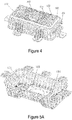
- FIG. 4 illustrates an airbag housing according to embodiment 3 of the present invention.
- the construction of the airbag housing according to embodiment 3 is substantially the same as the construction of the airbag housing according to embodiment 1.
- a major difference lies in that the first bottom wall ribs 121 of the airbag housing according to embodiment 3 may extend from the periphery of the jointing part 103 to any position on the bottom wall 102 and do not necessarily extend to the side wall 101; and additional bottom wall ribs 125 and the like may be provided and extend from the first bottom wall ribs 121 to the side wall.
- FIG. 5A and FIG. 5B illustrate an airbag housing according to embodiment 4 of the present invention.
- the construction of the airbag housing according to embodiment 4 is substantially the same as the construction of the airbag housing according to embodiment 1.
- a major difference lies in that the jointing part 103 is constructed to protrude towards an opening direction of the chamber, such that a concave part is formed between an outer side of the bottom wall 102 and a corresponding position on the jointing part 103, and that the jointing part 103 is closer to the opening of the chamber than other parts of the bottom wall 102.
- Adopting this construction can accommodate components such as the gas generator at the concave part of the bottom wall, thereby saving mounting space.
- connecting parts 133 formed between the jointing part 103 and other parts of the bottom wall may also be formed as a hollowed-out structure.
- the present invention further provides a safety airbag assembly, which comprises a gas generator, a safety airbag, and the airbag housing according to the above-mentioned embodiments.
- the hollowed-out structure of the side wall 101 comprises a plurality of first side wall ribs 111.
- the side wall 101 may also be provided in other constructions as long as the side wall 101 has a hollowed-out structure.
- the side wall 101 is provided with a plurality of run-though holes disposed distributively.
- the bottom wall is formed to be quadrilateral. Therefore, the side wall 101 comprises four side wall portions.
- the present invention is not limited thereto. According to needs, the bottom wall may be in other shapes such as polygonal shapes, elliptical shapes or other irregular shapes. Under this situation, the side wall may correspondingly extend around the bottom wall to form a chamber.
- the present invention is not limited thereto.
- the number of the second side wall ribs 112 on the side wall is not limited and may be equal to or greater than two.
- the second side wall ribs 112 are substantially perpendicularly intersected with the first side wall ribs 111.
- the present invention is not limited thereto.
- the second side wall ribs 112 on the sub-side walls may also be obliquely intersected with the first side wall ribs 111.
- first side wall ribs 111 are in a rectangular strip-shaped structure and a plate-type structure.
- shape of the first side wall ribs 111 is not limited thereto.
- the first side wall ribs 111 may be constructed to be in other various shapes.
- the second side wall ribs 112 are strip-shaped or the cross section is sector-shaped.
- the shape of the cross section of the second side wall ribs 112 is not limited thereto.
- the second side wall ribs 112 may be constructed to be in other various shapes.
- the cross section of the second side wall ribs 112 is constructed to be circular or elliptical.
- the bottom wall 102 is constructed to comprise the first bottom wall ribs 121 and second bottom wall ribs 122 intersected with the first bottom wall ribs.
- the present invention is not limited thereto. As long as other parts than the jointing part of the bottom wall 102 are constructed as a hollowed-out structure, the other parts may be formed as any other structures.
- first side wall ribs 111 are provided at substantially uniform intervals
- a scenario where the intervals between the first side wall ribs 111 change with the depth of the airbag housing is further described.
- the interval distribution situation of the first side wall ribs 111 may also be additionally arranged according to needs.
- the present invention is not limited thereto.
- Other methods such as stamping and 3D printing may also be adopted to form the airbag housing provided by the present invention.
Landscapes
- Engineering & Computer Science (AREA)
- Mechanical Engineering (AREA)
- Air Bags (AREA)
Abstract
Description
- The present invention relates to the vehicle safety airbag technology, and in particular, to an airbag housing. The present invention further relates to a safety airbag assembly comprising the above-mentioned airbag housing.
- An existing automobile safety airbag assembly usually includes a safety airbag, a gas generator, and an airbag housing for accommodating the aforesaid elements. The safety airbag assembly is mounted onto an airbag cover at a respective position of a vehicle. When an emergency collision occurs at the vehicle, the gas generator is started in response to an output of a collision sensor to generate an expansion gas to inflate the safety airbag. The safety airbag thereby bursts through the airbag cover and enters the carriage to protect occupants (such as the driver and/or the passengers) of the vehicle.
- Specifically,
FIG. 1A illustrates a vehicle safety airbag assembly in the prior art. As illustrated inFIG. 1A , a vehiclesafety airbag assembly 10 comprises anairbag cover 1, a foldedsafety airbag 2, a pressing ring 3, an airbag housing 4, a gas generator 5, asupport 6, nuts 7, and a wire harness 8 connected to the gas generator 5. A bottom center of the airbag housing 4 is provided with an interface part for mounting other components such as the gas generator 5. The interface part is provided with a central through hole. During mounting, an upper portion of the gas generator 5 sequentially passes through the central through hole of the interface part of the airbag housing 4 and the central through hole of the pressing ring 3, and is inserted into the central hole of thesafety airbag 2. Moreover, four bolts respectively protrude from mounting holes on the bottommost layer of the safety airbag, sequentially passing through mounting holes on a bottom plate of the airbag housing 4 and on flanges of the gas generator 5, and thesupport 6, and are finally fixed through the nuts 7. In this way, the pressing ring 3 fixes the bottommost layer of thesafety airbag 2 onto the bottom plate of the airbag housing 4. When a collision or a crash occurs at the vehicle, the gas generator 5 receives a signal transmitted through a wire harness connected to the gas generator 5, triggering an explosion. The gas generated from the explosion rapidly inflates the foldedsafety airbag 2. The inflated safety airbag expands and then bursts through theairbag cover 1 to enter the carriage, so as to prevent the occupants in the carriage from being injured by the impact. -
FIG. 1B illustrates atypical airbag housing 200 according to the prior art. Theairbag housing 200 can be used as the airbag housing 4 in the safety airbag assembly illustrated inFIG. 1A . As illustrated inFIG. 1B , theairbag housing 200 has abottom wall 202 and aside wall 201, wherein thebottom wall 202 and theside wall 201 form a chamber for accommodating the safety airbag. Thebottom wall 202 of theairbag housing 200 is provided with ajointing part 203 for mounting other components of the safety airbag assembly. Moreover, thejointing part 203 is provided with aninterface 231 formed as a through hole. At present, such airbag housing is mainly made of materials such as metal (like steel or aluminum), glass fiber, or synthetic resin through techniques such as injection molding, deep drawing, stamping and/or welding. If a common PA/40% glass fiber material is adopted, the weight of such airbag housing is usually 380-700 g. If a metal material is adopted, the weight is even heavier. - In recent years, energy saving, environmental protection, and cost reduction become subjects of pursuit of many industries due to continuous deterioration of the global environment. Specifically, for the automobile industry, governments of all countries including China put forward increasingly strict emission standards. For components and parts, main machine manufacturers put forward increasingly high cost requirements. Likewise, the weight and cost of the airbag housing also need to be adapted to meet the increasingly high requirements. However, the airbag housing (as illustrated in
FIG. 1B ) in the prior art is comparatively heavy in weight and high in cost. Therefore, an airbag housing which is light in weight, low in cost, and is capable of maintaining adequate strength is desired. - The purpose of the present invention is to provide an airbag housing, which is light in weight, low in cost, and capable of maintaining adequate strength, and a safety airbag assembly comprising the airbag housing.
- The present invention provides an airbag housing, which is used in a safety airbag assembly. The airbag housing comprises: a bottom wall, comprising a jointing part used for mounting other components of the safety airbag assembly provided thereon; the jointing part being provided with an interface formed as a through hole; and a side wall forming a chamber with the bottom wall, wherein at least a part or all of the side wall is constructed as a hollowed-out structure. According to the present invention, since at least a part of the side wall is constructed as a hollowed-out structure, the amount of materials used can be significantly reduced, and the adequate strength can be maintained at the same time.
- According to an embodiment of the present invention, the hollowed-out structure of the side wall may comprise a plurality of first side wall ribs provided at intervals, extending from a periphery of the bottom wall. According to an embodiment of the present invention, the hollowed-out structure of the side wall may further comprise second side wall ribs intersecting with the first side wall ribs. In such embodiment, by adopting a plurality of ribs, the structure is easy to manufacture; the amount of materials used can be reduced; and the structure of the plurality of ribs can well bear pulling-pressing stress and bending stress, maintain the strength of the airbag housing.
- According to an embodiment of the present invention, reinforcing ribs may be further provided at positions where the first side wall ribs and the bottom wall are connected. In such an embodiment, by providing reinforcing ribs at positions such as connecting positions where stress is easily accumulated, the strength of the airbag housing can be better maintained; and the capability of the housing in resisting impact deformation is improved.
- According to an embodiment of the present invention, parts other than the jointing part of the bottom wall comprise a plurality of the first bottom wall ribs arranged at intervals, extending outward from an edge of the jointing part, and a plurality of the second bottom wall ribs extending in an intersecting manner with the first bottom wall ribs, such that the plurality of the first bottom wall ribs and the plurality of the second bottom wall ribs form a latticed structure comprising a plurality of lattices. In such an embodiment, the latticed structure of the bottom wall can significantly reduce the amount of materials used while preserving strength. In addition, if a solid structure is kept near the jointing part of the bottom wall, the solid structure may be used for absorbing heat produced by the gas generator mounted at this position and improving impact strength at this position.
- According to an embodiment of the present invention, the airbag housing further comprises third bottom wall ribs obliquely extending from a middle of one side of at least one of the plurality of the lattices to a middle of another side. The structural strength can be improved with such third bottom wall ribs disposed in place. Moreover, when adopting molding methods such as injection molding during manufacturing, such third bottom wall ribs can facilitate the flow of the molding material and avoid defects of finished products.
- According to an embodiment of the present invention, the jointing part is provided with a plurality of run-though holes arranged distributively. In such an embodiment, the plurality of run-through holes can reduce the amount of materials used for the jointing part and thus can reduce the amount of materials used for the airbag housing as a whole.
- According to an embodiment of the present invention, the airbag housing further comprises flanges provided at a periphery of the side wall away from the bottom wall. In such an embodiment, the flanges can facilitate the mounting and fixation of the connecting structure when the airbag housing is fixed to the airbag cover or other vehicle parts.
- According to an embodiment of the present invention, reinforcing ribs are further provided at positions where the flanges and the side wall are connected. In such an embodiment, providing reinforcing ribs at positions such as connecting positions where stress is easily accumulated better maintains the strength of the airbag housing; and the capability of the housing in resisting impact deformation is improved.
- According to an embodiment of the present invention, the jointing part is constructed to protrude toward an opening of the chamber, such that a concave part is formed between an outer side of the bottom wall and a position corresponding to the jointing part, and that the jointing part is closer to the opening of the chamber than other parts of the bottom wall. In such an embodiment, the concave part on the outer side of the bottom wall of the airbag housing can be used for accommodating other components such as a gas generator of the airbag assembly, so as to save space.
- According to an embodiment of the present invention, the first side wall ribs are constructed as a plate-type structure. The first side wall ribs being plate-type can provide improved strength, such that the airbag housing has stronger capability in resisting impact deformation.
- The present invention further provides a safety airbag assembly, which comprises a gas generator, a safety airbag, and the airbag housing according to any one of the above-mentioned embodiments. Adopting the safety airbag assembly provided by the present invention can achieve the goal of having a safety airbag assembly that is light in weight, low in cost, and capable of maintaining adequate strength.
- The features, advantages, and technical effects of the embodiments of the present invention will be described below with reference to drawings. In the drawings, the same reference sign represents the same elements:
-
FIG. 1A illustrates an exploded diagram of an airbag housing assembly according to the prior art. -
FIG. 1B illustrates a stereoscopic view of the airbag housing according to the prior art. -
FIG. 2A illustrates a stereoscopic view of an airbag housing according toembodiment 1 of the present invention. -
FIG. 2B illustrates a stereoscopic view of the airbag housing according toembodiment 1 of the present invention. -
FIG. 2C illustrates a front view of the airbag housing according toembodiment 1 of the present invention. -
FIG. 3A illustrates a stereoscopic view of an airbag housing according toembodiment 2 of the present invention. -
FIG. 3B illustrates a stereoscopic view of the airbag housing according toembodiment 2 of the present invention. -
FIG. 4 illustrates a stereoscopic view of an airbag housing according to embodiment 3 of the present invention. -
FIG. 5A illustrates a stereoscopic view of an airbag housing according to embodiment 4 of the present invention. -
FIG. 5B illustrates a stereoscopic view of the airbag housing according to embodiment 4 of the present invention. - The embodiments of the present invention will be described below with reference to the drawings. The detailed description and drawings below are used exemplarily for illustrating the principles of the present invention. The present invention is not limited to the described preferred embodiments. The scope of the present invention is defined by the claims.
- Airbag housings and safety airbag assemblies according to the embodiments of the present invention will be described below with reference to
FIGS. 2A-5B . -
FIG. 2A to FIG. 2C illustrate an airbag housing according toembodiment 1 of the present invention. As illustrated inFIG. 2A , the airbag housing comprises abottom wall 102 and aside wall 101, wherein thebottom wall 102 and theside wall 101 jointly form a chamber. The chamber usually is used for accommodating components such as an airbag. Ajointing part 103 used for mounting other components of the safety airbag assembly is provided on thebottom wall 102. Thejointing part 103 is provided with aninterface 131 formed as a through hole. Preferably, when the airbag housing and other components are mounted to form a safety airbag assembly, the airbag presses against and is mounted to thejointing part 103 of the airbag housing. A gas generator may pass through theinterface 131 and be mounted to and aligned with an inflation port of the airbag. - As illustrated in
FIG. 2A , theentire side wall 101 of the airbag housing is constructed as a hollowed-out structure. According to another embodiment of the present invention, theside wall 101 of the airbag housing may also be constructed as only having a partial hollowed-out structure. Compared with the airbag housing in the prior art, the airbag housing in the present invention which is wholly or at least partially constructed as a hollowed-out structure is lighter in weight and lower in cost. - As illustrated in
FIG. 2A , theside wall 101 comprises a plurality of firstside wall ribs 111 which are arranged at intervals and extend from a periphery of thebottom wall 102. Preferably, the firstside wall ribs 111 on each sub-side wall are substantially uniformly arranged at intervals along the periphery of thebottom wall 102. Preferably, each of the plurality of the firstside wall ribs 111 on each sub-side wall has a substantially consistent width in a respective extension direction. Therefore, the sub-side walls of the airbag housing are uniform in strength at all positions, such that when the safety airbag is expanded, the airbag housing is not easily damaged. In addition, the intervals between the first side wall ribs may be arranged according to needs. For example, at positions where a greater depth of the chamber causes the height of the side wall to be higher, the intervals between two adjacent firstside wall ribs 111 may be properly reduced, so as to guarantee that the airbag housing has an enough capability to resist impact deformation. When a shallower depth of the chamber causes the height of the side wall to be shorter, the intervals between two adjacent firstside wall ribs 111 may be set to be greater, so as to guarantee that airbag housing is lighter in weight and lower in cost on the premise that the capability in resisting impact deformation is preserved. As illustrated inFIGS. 2A-2C , the firstside wall ribs 111 are constructed as a long strip-shaped structure. - In addition, the
side wall 101 may further comprise secondside wall ribs 112 intersected with the firstside wall ribs 111. The secondside wall ribs 112 are transversely intersected with the corresponding firstside wall ribs 111 and connect adjacent firstside wall ribs 111, such that a truss-like structure is formed through staggering. Therefore, the strength of the airbag housing can be improved and the capability in resisting impact deformation is improved. In the embodiment illustrated inFIGS. 2A-2C , the secondside wall ribs 112 are intersected with all of the firstside wall ribs 111. Preferably, the secondside wall ribs 112 on the sub-side walls are substantially perpendicularly intersected with the corresponding firstside wall ribs 111. In the embodiment illustrated inFIGS. 2A-2C , at a middle position of an extension length of each firstside wall rib 111, a secondside wall rib 112 is provided. The secondside wall ribs 112 are also constructed to be long strip-shaped. - In addition, reinforcing
ribs 113 are further provided at positions where the first side wall ribs and thebottom wall 102 are connected, as illustrated inFIG. 2A . Providing these reinforcing ribs reinforces the stress accumulation at the position near the connecting position of thebottom wall 102 and theside wall 101. Therefore, the capability of the airbag housing in resisting impact deformation is improved. - In addition, as illustrated in
FIG. 2B , parts other than thejointing part 103 of thebottom wall 102 comprise a plurality of the firstbottom wall ribs 121 which are disposed at intervals and extend outwards from an edge of thejointing part 103. As illustrated inFIGS. 2A and2B , thejointing part 103 is constructed to be substantially rectangular. Preferably, the firstbottom wall ribs 121 extend perpendicularly to the corresponding side of thejointing part 103. Preferably, the width of the firstbottom wall ribs 121 along a respective extension direction is consistent. Preferably, the firstbottom wall ribs 121 extend outwards from the periphery of thejointing part 103 to theside wall 101. - The
bottom wall 102 may further comprise a plurality of secondbottom wall ribs 122 which extend in a way intersecting with the firstbottom wall ribs 121, such that other parts than thejointing part 103 of thebottom wall 102 form a latticed structure comprising a plurality of lattices. This latticed structure can improve the strength and thus improve the capability of the airbag housing in resisting impact deformation. Preferably, the secondbottom wall ribs 122 are perpendicular to the firstbottom wall ribs 121 and are arranged at uniform intervals along an extension direction of the firstbottom wall ribs 121. - In addition, the
bottom wall 102 further comprises thirdbottom wall ribs 123 which obliquely extend from a middle of one side of at least one of the plurality of lattices to a middle of another side. By this construction, When the airbag housing is injection-molded, adopting this construction makes the injection molding materials easy to flow into a central portion of each side of the lattices. Therefore, the airbag housing is not easily defective. In addition, the injection molding materials can rapidly flow. The manufacturing time of the airbag housing is then shortened; and manufacturing efficiency is improved. According toembodiment 1 of the present invention, a plurality of the thirdbottom wall ribs 123 may be connected head-to-tail to form a zigzag line, so as to connect all of the firstbottom wall ribs 121 along a transverse direction of each firstbottom wall rib 121. In this way, the flow of the injection molding materials can be further accelerated; and the capability of the airbag housing in resisting impact deformation is improved. - In addition, as illustrated in
FIG. 2A , the airbag housing further comprisesflanges 104 which are provided at a periphery of theside wall 101, away from thebottom wall 102. When the airbag housing and other components form an airbag assembly and the airbag assembly is mounted to a vehicle, theflanges 104 are fit with an airbag cover covering the chamber of the airbag housing or a jointing part for mounting the airbag housing at a corresponding position of the vehicle, so as to mount the airbag assembly to a corresponding position. As illustrated inFIG. 2A , theflanges 104 are disposed along a portion of the periphery of theside wall 101, away from thebottom wall 102. Inembodiment 1 of the present invention, as illustrated inFIG. 2A , sevenflanges 104 are provided at intervals along the periphery of the side wall. The positions and number of the flanges may be arranged according to needs. In addition, flanges that extend continusly may be further provided along the periphery of the side wall. On the other hand,constructing the flanges to be separately provided along a portion of the periphery of the side wall can further reduce the weight. - As illustrated in
FIG. 2B , reinforcingribs 141 are further provided at positions where theflanges 104 and theside wall 101 are connected. Preferably, as illustrated inFIG. 2B , the reinforcingribs 141 may further extend along theside wall 101 connected with theflanges 104, so as to further reinforce the side wall. Areas of the reinforcingribs 141, i.e., positions corresponding to the flanges, are usually areas in which the airbag assembly is fixedly connected with mounting positions such as a panel of the vehicle. As a result, providing the reinforcingribs 141 enables the airbag housing to better bear the stress produced at the position where the airbag housing is fixedly connected with the mounting area. - As illustrated in
FIG. 2C , inembodiment 1 of the present invention, the airbag housing is constructed to be in a quadrangular frustum pyramid shape; and the cross-sectional area of the airbag housing gradually decreases from the opening of the chamber to thebottom wall 102. In other words, the airbag housing has a certain draft angle. By adopting a design with the draft angle, the airbag housing can be better manufactured through the injection molding process; the hollowed-out structures of the side wall and the bottom wall can be manufactured through a pair of upper and lower dies only; and other assistant molding tools (such as sliders) are not needed. When the airbag housing has the draft angle, the plurality of the firstside wall ribs 111 are radially distributed from the periphery of thebottom wall 102 to the opening of the chamber. - In addition,
bottom wall ribs 124 may be further constructed onto at least one portion of the outer side of the bottom wall of thejointing part 103 of the airbag housing. Preferably, thebottom wall ribs 124 are constructed to be latticed at positions corresponding to thejointing part 103 on the outer side of thebottom wall 102. Preferably, thebottom wall ribs 124 may also extend through the first bottom wall ribs and the third bottom wall ribs. When the gas generator is detonated, the heat absorbed at thejointing part 103 is maximal and thus the impact strength of thejointing part 103 usually needs to be greater than that of other parts of thebottom wall 102. Thejointing part 103 of the airbag housing having the above-mentioned construction can enable the weight of the airbag housing to be lighter on the premise that the impact strength is guaranteed. - In
embodiment 1 of the present invention, the airbag housing may be made of a PA/LGF composite material, a PP/LGF composite material, or a PA/40% glass fiber composite material. Taking the airbag housing made of the PA/40% glass fiber composite material as an example, the range of the weight of the airbag housing in the prior art is 380 g-700 g. The weight of the airbag housing illustrated inFIG. 2A to FIG. 2F according to the present invention is about 220 g. Since the side wall and the bottom wall of the airbag housing according to the present invention are constructed to be a hollowed-out structure, the removal of this part of materials has an obvious beneficial effect on the optimization of the weight of the entire airbag housing and the strength is maintained at the same time. -
FIG. 3A and FIG. 3B illustrate an airbag housing according toembodiment 2 of the present invention. The airbag housing according toembodiment 2 is substantially the same as the airbag housing according toembodiment 1. A major difference lies in that the firstside wall ribs 111 of the airbag housing according toembodiment 2 are constructed as a plate-type structure. - As illustrated in
FIGS. 3A and 3B , preferably, a plane on which plate-like firstside wall ribs 111 are located is substantially perpendicular to the periphery of thebottom wall 102 connected with the firstside wall ribs 111. The plate-like firstside wall ribs 111 can further improve the strength such that the airbag housing has greater capability in resisting impact deformation. - In addition, as illustrated in
FIGS. 3A and 3B , theflanges 104 of the airbag housing according toembodiment 2 may be provided along the entire periphery of theside wall 101. Preferably, theflanges 104 may also be provided as a hollowed-out structure. - In addition, the cross section of the second
side wall ribs 112 of the airbag housing according toembodiment 2 is constructed to be sector-shaped. - In addition, the first
side wall ribs 111 of the airbag housing according toembodiment 2 do not continuously surround the entire side wall. Instead, two firstside wall ribs 111 are provided and are respectively intersected with the plurality of secondside wall ribs 112 on two side wall portions corresponding to long sides of the bottom wall. - In addition, as illustrated in
FIG. 3B , thejointing part 103 of the airbag housing according toembodiment 2 is provided with a plurality of run-thoughholes 132 arranged distributively, such that the weight of the airbag housing is further reduced. -
FIG. 4 illustrates an airbag housing according to embodiment 3 of the present invention. The construction of the airbag housing according to embodiment 3 is substantially the same as the construction of the airbag housing according toembodiment 1. A major difference lies in that the firstbottom wall ribs 121 of the airbag housing according to embodiment 3 may extend from the periphery of thejointing part 103 to any position on thebottom wall 102 and do not necessarily extend to theside wall 101; and additionalbottom wall ribs 125 and the like may be provided and extend from the firstbottom wall ribs 121 to the side wall. -
FIG. 5A andFIG. 5B illustrate an airbag housing according to embodiment 4 of the present invention. The construction of the airbag housing according to embodiment 4 is substantially the same as the construction of the airbag housing according toembodiment 1. A major difference lies in that thejointing part 103 is constructed to protrude towards an opening direction of the chamber, such that a concave part is formed between an outer side of thebottom wall 102 and a corresponding position on thejointing part 103, and that thejointing part 103 is closer to the opening of the chamber than other parts of thebottom wall 102. Adopting this construction can accommodate components such as the gas generator at the concave part of the bottom wall, thereby saving mounting space. - Preferably, connecting
parts 133 formed between thejointing part 103 and other parts of the bottom wall may also be formed as a hollowed-out structure. - The present invention further provides a safety airbag assembly, which comprises a gas generator, a safety airbag, and the airbag housing according to the above-mentioned embodiments.
- As described above, although the exemplary embodiments of the present invention have already been described in the description with reference to the drawings, the present invention is not limited to the above-mentioned embodiments and may also have many other embodiments.
- In the above-mentioned embodiments, it is described that the hollowed-out structure of the
side wall 101 comprises a plurality of firstside wall ribs 111. However, the present invention is not limited thereto. Theside wall 101 may also be provided in other constructions as long as theside wall 101 has a hollowed-out structure. For example, theside wall 101 is provided with a plurality of run-though holes disposed distributively. - In the above-mentioned embodiments, the bottom wall is formed to be quadrilateral. Therefore, the
side wall 101 comprises four side wall portions. However, the present invention is not limited thereto. According to needs, the bottom wall may be in other shapes such as polygonal shapes, elliptical shapes or other irregular shapes. Under this situation, the side wall may correspondingly extend around the bottom wall to form a chamber. - In the above-mentioned embodiments, a scenario where the number of the second
side wall ribs 112 on the side wall portion corresponding to one edge of the bottom wall being one is described, as illustrated inFIG. 2A . However, the present invention is not limited thereto. The number of the secondside wall ribs 112 on the side wall is not limited and may be equal to or greater than two. - In the above-mentioned embodiments, it is described that the second
side wall ribs 112 are substantially perpendicularly intersected with the firstside wall ribs 111. However, the present invention is not limited thereto. The secondside wall ribs 112 on the sub-side walls may also be obliquely intersected with the firstside wall ribs 111. - In the above-mentioned embodiments, it is described that the first
side wall ribs 111 are in a rectangular strip-shaped structure and a plate-type structure. However, the shape of the firstside wall ribs 111 is not limited thereto. The firstside wall ribs 111 may be constructed to be in other various shapes. - In the above-mentioned embodiments, a scenario where the second
side wall ribs 112 are strip-shaped or the cross section is sector-shaped is provided. However, the shape of the cross section of the secondside wall ribs 112 is not limited thereto. The secondside wall ribs 112 may be constructed to be in other various shapes. For example, the cross section of the secondside wall ribs 112 is constructed to be circular or elliptical. - In the above-mentioned embodiments, it is described that the
bottom wall 102 is constructed to comprise the firstbottom wall ribs 121 and secondbottom wall ribs 122 intersected with the first bottom wall ribs. However, the present invention is not limited thereto. As long as other parts than the jointing part of thebottom wall 102 are constructed as a hollowed-out structure, the other parts may be formed as any other structures. - In the above-mentioned embodiments, a scenario where the first
side wall ribs 111 are provided at substantially uniform intervals is described, and a scenario where the intervals between the firstside wall ribs 111 change with the depth of the airbag housing is further described. However, the interval distribution situation of the firstside wall ribs 111 may also be additionally arranged according to needs. - In the above-mentioned embodiments, a scenario where the airbag housing is formed by adopting an injection molding process is described. However, the present invention is not limited thereto. Other methods such as stamping and 3D printing may also be adopted to form the airbag housing provided by the present invention.
- Although the present invention has already been described with reference to the exemplary embodiments, it shall be understood that the present invention is not limited to the constructions and methods described in the above-mentioned embodiments. Instead, the present invention intends to cover various modification examples and equivalent configurations. In addition, although various elements and method steps of the disclosed invention are described in various exemplary combinations and constructions, other combinations comprising more or fewer elements or methods also fall into the scope of the present invention.
Claims (12)
- An airbag housing used in a safety airbag assembly, the airbag housing comprising:a bottom wall comprising a jointing part used for mounting other components of the safety airbag assembly provided thereon; the jointing part being provided with an interface formed as a through hole; anda side wall forming a chamber with the bottom wall, whereinat least a part or all of the side wall is constructed as a hollowed-out structure.
- The airbag housing according to claim 1, wherein the hollowed-out structure of the side wall comprises a plurality of a first side wall ribs arranged at intervals, extending from a periphery of the bottom wall.
- The airbag housing according to claim 2, wherein the hollowed-out structure of the side wall further comprises second side wall ribs intersecting with the first side wall ribs.
- The airbag housing according to claim 2 or 3, wherein reinforcing ribs are further provided at positions where the first side wall ribs and the bottom wall are connected.
- The airbag housing according to any one of claims 1 to 3, wherein parts other than the jointing part of the bottom wall comprise a plurality of the first bottom wall ribs provided at intervals, extending outward from an edge of the jointing part, and a plurality of the second bottom wall ribs extending in an intersecting manner with the first bottom wall ribs, such that the plurality of the first bottom wall ribs and the plurality of the second bottom wall ribs form a latticed structure comprising a plurality of lattices.
- The airbag housing according to claim 5, wherein the airbag housing further comprises third bottom wall ribs obliquely extending from a middle of one side of at least one of the plurality of the lattices to a middle of another side.
- The airbag housing according to claim 5, wherein the jointing part is provided with a plurality of run-though holes arranged distributively.
- The airbag housing according to claim 1, wherein the airbag housing further comprises flanges provided at a periphery of the side wall away from the bottom wall.
- The airbag housing according to claim 8, wherein reinforcing ribs are further provided at positions where the flanges and the side wall are connected.
- The airbag housing according to claim 1, wherein the jointing part is constructed to protrude toward an opening of the chamber, such that a concave part is formed between an outer side of the bottom wall and a corresponding position on the jointing part, and that the jointing part is closer to the opening of the chamber than other parts of the bottom wall.
- The airbag housing according to claim 5, wherein the first side wall ribs are constructed as a plate-type structure.
- A safety airbag assembly, comprising:a gas generator;a safety airbag; andthe airbag housing according to any one of claims 1 to 11.
Applications Claiming Priority (2)
| Application Number | Priority Date | Filing Date | Title |
|---|---|---|---|
| CN201610073716.3A CN107031556B (en) | 2016-02-02 | 2016-02-02 | Airbag housing and airbag module |
| PCT/CN2016/113483 WO2017133365A1 (en) | 2016-02-02 | 2016-12-30 | Airbag housing and airbag assembly |
Publications (3)
| Publication Number | Publication Date |
|---|---|
| EP3412515A1 true EP3412515A1 (en) | 2018-12-12 |
| EP3412515A4 EP3412515A4 (en) | 2019-09-18 |
| EP3412515B1 EP3412515B1 (en) | 2020-09-30 |
Family
ID=59500526
Family Applications (1)
| Application Number | Title | Priority Date | Filing Date |
|---|---|---|---|
| EP16889171.1A Active EP3412515B1 (en) | 2016-02-02 | 2016-12-30 | Airbag housing and airbag assembly |
Country Status (3)
| Country | Link |
|---|---|
| EP (1) | EP3412515B1 (en) |
| CN (1) | CN107031556B (en) |
| WO (1) | WO2017133365A1 (en) |
Families Citing this family (3)
| Publication number | Priority date | Publication date | Assignee | Title |
|---|---|---|---|---|
| US11285900B1 (en) * | 2020-10-22 | 2022-03-29 | Ford Global Technologies, Llc | Airbag housing |
| CN117246269A (en) * | 2022-06-10 | 2023-12-19 | 采埃孚汽车科技(张家港)有限公司 | Air bag housing, overhead air bag and vehicle |
| CN120116879B (en) * | 2025-04-02 | 2026-05-05 | 奇瑞汽车股份有限公司 | A passenger-side airbag assembly and vehicle dashboard |
Family Cites Families (15)
| Publication number | Priority date | Publication date | Assignee | Title |
|---|---|---|---|---|
| JPH06127322A (en) * | 1992-10-16 | 1994-05-10 | Takata Kk | Air bag device for front passenger's seat |
| DE19538870C2 (en) * | 1995-10-19 | 2002-10-24 | Mst Automotive Gmbh | Housing for an airbag module |
| US6176511B1 (en) * | 1998-10-07 | 2001-01-23 | Trw Inc. | Air bag module |
| JP4666676B2 (en) * | 2004-10-27 | 2011-04-06 | 日本プラスト株式会社 | Airbag device |
| DE102005004451A1 (en) * | 2005-02-01 | 2006-08-10 | Adam Opel Ag | Airbag housing for safety arrangement in motor vehicle, has folded, inflatable airbag contained in airbag chamber, where housing part forming airbag chamber is designed using grids |
| EP2221224B1 (en) * | 2009-02-24 | 2015-07-15 | Autoliv Development AB | Housing assembly for an airbag module |
| JP5543727B2 (en) * | 2009-05-12 | 2014-07-09 | オートリブ ディベロップメント エービー | Airbag device for passenger seat |
| KR101042738B1 (en) * | 2009-12-09 | 2011-06-20 | 아우토리브 디벨롭먼트 아베 | Ultralight Passenger Airbag Module |
| CN202879418U (en) * | 2012-11-02 | 2013-04-17 | 浙江正邦汽车模具有限公司 | Shell of automotive airbag |
| CN203438974U (en) * | 2013-08-22 | 2014-02-19 | 浙江正邦汽车模具有限公司 | Spot welding type automobile safety air bag shell body |
| CN203637760U (en) * | 2013-10-23 | 2014-06-11 | 浙江正邦汽车模具有限公司 | Automobile supplementary restraint system casing |
| CN105083199B (en) * | 2014-05-12 | 2018-11-20 | 奥托立夫开发公司 | A kind of safe automobile air bag shell |
| CN104015684B (en) * | 2014-06-08 | 2016-08-17 | 锦州锦恒汽车安全系统有限公司 | Safe automobile air bag shell structure |
| CN105922964B (en) * | 2016-06-22 | 2018-11-30 | 延锋百利得(上海)汽车安全系统有限公司 | A kind of air bag device |
| CN205801021U (en) * | 2016-06-22 | 2016-12-14 | 延锋百利得(上海)汽车安全系统有限公司 | A kind of light-weighted air bag device |
-
2016
- 2016-02-02 CN CN201610073716.3A patent/CN107031556B/en active Active
- 2016-12-30 EP EP16889171.1A patent/EP3412515B1/en active Active
- 2016-12-30 WO PCT/CN2016/113483 patent/WO2017133365A1/en not_active Ceased
Also Published As
| Publication number | Publication date |
|---|---|
| WO2017133365A1 (en) | 2017-08-10 |
| EP3412515B1 (en) | 2020-09-30 |
| CN107031556B (en) | 2022-03-01 |
| CN107031556A (en) | 2017-08-11 |
| EP3412515A4 (en) | 2019-09-18 |
Similar Documents
| Publication | Publication Date | Title |
|---|---|---|
| KR20210107682A (en) | Vehicle locker structure and method for obtaining the same | |
| EP3412515B1 (en) | Airbag housing and airbag assembly | |
| EP0558240A1 (en) | Continuous circumference diffuser reaction canister | |
| US6712410B2 (en) | Extruded aluminum bumper | |
| US10696262B2 (en) | Safety airbag housing and safety airbag assembly | |
| US9701267B1 (en) | Vehicle body transformable front section structure | |
| KR20120024558A (en) | Deformable cross-car beam for side impact protection | |
| KR20190078936A (en) | Case for electric vehicle | |
| JPH11348699A (en) | Shock absorbing structure for vehicle interior parts | |
| EP3468842B1 (en) | Bumper for a motor vehicle and method for its production | |
| US8226159B2 (en) | Vehicle body, more particularly land vehicle body | |
| US20210114663A1 (en) | Multi-cell energy absorbing structures | |
| JP2019507057A (en) | Impact energy absorption structure | |
| US9358944B1 (en) | Active bolster with hot-weld rivets | |
| US20080265550A1 (en) | Airbag module | |
| JP4865379B2 (en) | Automotive bumper equipment | |
| US8052167B2 (en) | Airbag assembly | |
| US11066039B2 (en) | Gas generator container and airbag module | |
| US7374198B2 (en) | Airbag module canister | |
| KR102107488B1 (en) | Underfloor reinforcement structure of vehicle body | |
| JP2016034825A (en) | Vehicle fender energy absorbing apparatus | |
| KR102093120B1 (en) | Battery case for electric vehicle | |
| KR101010594B1 (en) | Filter for inflator of automotive airbag unit | |
| JP2006298013A (en) | Vehicle hood structure | |
| CN116419881A (en) | Accumulator housing for an accumulator of a motor vehicle |
Legal Events
| Date | Code | Title | Description |
|---|---|---|---|
| STAA | Information on the status of an ep patent application or granted ep patent |
Free format text: STATUS: THE INTERNATIONAL PUBLICATION HAS BEEN MADE |
|
| PUAI | Public reference made under article 153(3) epc to a published international application that has entered the european phase |
Free format text: ORIGINAL CODE: 0009012 |
|
| STAA | Information on the status of an ep patent application or granted ep patent |
Free format text: STATUS: REQUEST FOR EXAMINATION WAS MADE |
|
| 17P | Request for examination filed |
Effective date: 20180725 |
|
| AK | Designated contracting states |
Kind code of ref document: A1 Designated state(s): AL AT BE BG CH CY CZ DE DK EE ES FI FR GB GR HR HU IE IS IT LI LT LU LV MC MK MT NL NO PL PT RO RS SE SI SK SM TR |
|
| AX | Request for extension of the european patent |
Extension state: BA ME |
|
| DAV | Request for validation of the european patent (deleted) | ||
| DAX | Request for extension of the european patent (deleted) | ||
| A4 | Supplementary search report drawn up and despatched |
Effective date: 20190816 |
|
| RIC1 | Information provided on ipc code assigned before grant |
Ipc: B60R 21/217 20110101ALI20190809BHEP Ipc: B60R 21/20 20110101AFI20190809BHEP |
|
| GRAP | Despatch of communication of intention to grant a patent |
Free format text: ORIGINAL CODE: EPIDOSNIGR1 |
|
| STAA | Information on the status of an ep patent application or granted ep patent |
Free format text: STATUS: GRANT OF PATENT IS INTENDED |
|
| INTG | Intention to grant announced |
Effective date: 20200618 |
|
| GRAS | Grant fee paid |
Free format text: ORIGINAL CODE: EPIDOSNIGR3 |
|
| GRAA | (expected) grant |
Free format text: ORIGINAL CODE: 0009210 |
|
| STAA | Information on the status of an ep patent application or granted ep patent |
Free format text: STATUS: THE PATENT HAS BEEN GRANTED |
|
| AK | Designated contracting states |
Kind code of ref document: B1 Designated state(s): AL AT BE BG CH CY CZ DE DK EE ES FI FR GB GR HR HU IE IS IT LI LT LU LV MC MK MT NL NO PL PT RO RS SE SI SK SM TR |
|
| REG | Reference to a national code |
Ref country code: GB Ref legal event code: FG4D Ref country code: CH Ref legal event code: EP |
|
| REG | Reference to a national code |
Ref country code: AT Ref legal event code: REF Ref document number: 1318474 Country of ref document: AT Kind code of ref document: T Effective date: 20201015 |
|
| REG | Reference to a national code |
Ref country code: DE Ref legal event code: R096 Ref document number: 602016045213 Country of ref document: DE |
|
| REG | Reference to a national code |
Ref country code: IE Ref legal event code: FG4D |
|
| PG25 | Lapsed in a contracting state [announced via postgrant information from national office to epo] |
Ref country code: SE Free format text: LAPSE BECAUSE OF FAILURE TO SUBMIT A TRANSLATION OF THE DESCRIPTION OR TO PAY THE FEE WITHIN THE PRESCRIBED TIME-LIMIT Effective date: 20200930 Ref country code: FI Free format text: LAPSE BECAUSE OF FAILURE TO SUBMIT A TRANSLATION OF THE DESCRIPTION OR TO PAY THE FEE WITHIN THE PRESCRIBED TIME-LIMIT Effective date: 20200930 Ref country code: GR Free format text: LAPSE BECAUSE OF FAILURE TO SUBMIT A TRANSLATION OF THE DESCRIPTION OR TO PAY THE FEE WITHIN THE PRESCRIBED TIME-LIMIT Effective date: 20201231 Ref country code: HR Free format text: LAPSE BECAUSE OF FAILURE TO SUBMIT A TRANSLATION OF THE DESCRIPTION OR TO PAY THE FEE WITHIN THE PRESCRIBED TIME-LIMIT Effective date: 20200930 Ref country code: BG Free format text: LAPSE BECAUSE OF FAILURE TO SUBMIT A TRANSLATION OF THE DESCRIPTION OR TO PAY THE FEE WITHIN THE PRESCRIBED TIME-LIMIT Effective date: 20201230 Ref country code: NO Free format text: LAPSE BECAUSE OF FAILURE TO SUBMIT A TRANSLATION OF THE DESCRIPTION OR TO PAY THE FEE WITHIN THE PRESCRIBED TIME-LIMIT Effective date: 20201230 |
|
| REG | Reference to a national code |
Ref country code: AT Ref legal event code: MK05 Ref document number: 1318474 Country of ref document: AT Kind code of ref document: T Effective date: 20200930 |
|
| PG25 | Lapsed in a contracting state [announced via postgrant information from national office to epo] |
Ref country code: RS Free format text: LAPSE BECAUSE OF FAILURE TO SUBMIT A TRANSLATION OF THE DESCRIPTION OR TO PAY THE FEE WITHIN THE PRESCRIBED TIME-LIMIT Effective date: 20200930 Ref country code: LV Free format text: LAPSE BECAUSE OF FAILURE TO SUBMIT A TRANSLATION OF THE DESCRIPTION OR TO PAY THE FEE WITHIN THE PRESCRIBED TIME-LIMIT Effective date: 20200930 |
|
| REG | Reference to a national code |
Ref country code: NL Ref legal event code: MP Effective date: 20200930 |
|
| REG | Reference to a national code |
Ref country code: LT Ref legal event code: MG4D |
|
| PG25 | Lapsed in a contracting state [announced via postgrant information from national office to epo] |
Ref country code: LT Free format text: LAPSE BECAUSE OF FAILURE TO SUBMIT A TRANSLATION OF THE DESCRIPTION OR TO PAY THE FEE WITHIN THE PRESCRIBED TIME-LIMIT Effective date: 20200930 Ref country code: CZ Free format text: LAPSE BECAUSE OF FAILURE TO SUBMIT A TRANSLATION OF THE DESCRIPTION OR TO PAY THE FEE WITHIN THE PRESCRIBED TIME-LIMIT Effective date: 20200930 Ref country code: PT Free format text: LAPSE BECAUSE OF FAILURE TO SUBMIT A TRANSLATION OF THE DESCRIPTION OR TO PAY THE FEE WITHIN THE PRESCRIBED TIME-LIMIT Effective date: 20210201 Ref country code: RO Free format text: LAPSE BECAUSE OF FAILURE TO SUBMIT A TRANSLATION OF THE DESCRIPTION OR TO PAY THE FEE WITHIN THE PRESCRIBED TIME-LIMIT Effective date: 20200930 Ref country code: SM Free format text: LAPSE BECAUSE OF FAILURE TO SUBMIT A TRANSLATION OF THE DESCRIPTION OR TO PAY THE FEE WITHIN THE PRESCRIBED TIME-LIMIT Effective date: 20200930 Ref country code: EE Free format text: LAPSE BECAUSE OF FAILURE TO SUBMIT A TRANSLATION OF THE DESCRIPTION OR TO PAY THE FEE WITHIN THE PRESCRIBED TIME-LIMIT Effective date: 20200930 |
|
| PG25 | Lapsed in a contracting state [announced via postgrant information from national office to epo] |
Ref country code: PL Free format text: LAPSE BECAUSE OF FAILURE TO SUBMIT A TRANSLATION OF THE DESCRIPTION OR TO PAY THE FEE WITHIN THE PRESCRIBED TIME-LIMIT Effective date: 20200930 Ref country code: IS Free format text: LAPSE BECAUSE OF FAILURE TO SUBMIT A TRANSLATION OF THE DESCRIPTION OR TO PAY THE FEE WITHIN THE PRESCRIBED TIME-LIMIT Effective date: 20210130 Ref country code: AT Free format text: LAPSE BECAUSE OF FAILURE TO SUBMIT A TRANSLATION OF THE DESCRIPTION OR TO PAY THE FEE WITHIN THE PRESCRIBED TIME-LIMIT Effective date: 20200930 Ref country code: AL Free format text: LAPSE BECAUSE OF FAILURE TO SUBMIT A TRANSLATION OF THE DESCRIPTION OR TO PAY THE FEE WITHIN THE PRESCRIBED TIME-LIMIT Effective date: 20200930 Ref country code: ES Free format text: LAPSE BECAUSE OF FAILURE TO SUBMIT A TRANSLATION OF THE DESCRIPTION OR TO PAY THE FEE WITHIN THE PRESCRIBED TIME-LIMIT Effective date: 20200930 |
|
| PG25 | Lapsed in a contracting state [announced via postgrant information from national office to epo] |
Ref country code: SK Free format text: LAPSE BECAUSE OF FAILURE TO SUBMIT A TRANSLATION OF THE DESCRIPTION OR TO PAY THE FEE WITHIN THE PRESCRIBED TIME-LIMIT Effective date: 20200930 Ref country code: NL Free format text: LAPSE BECAUSE OF FAILURE TO SUBMIT A TRANSLATION OF THE DESCRIPTION OR TO PAY THE FEE WITHIN THE PRESCRIBED TIME-LIMIT Effective date: 20200930 |
|
| REG | Reference to a national code |
Ref country code: DE Ref legal event code: R097 Ref document number: 602016045213 Country of ref document: DE |
|
| REG | Reference to a national code |
Ref country code: CH Ref legal event code: PL |
|
| PLBE | No opposition filed within time limit |
Free format text: ORIGINAL CODE: 0009261 |
|
| STAA | Information on the status of an ep patent application or granted ep patent |
Free format text: STATUS: NO OPPOSITION FILED WITHIN TIME LIMIT |
|
| PG25 | Lapsed in a contracting state [announced via postgrant information from national office to epo] |
Ref country code: MC Free format text: LAPSE BECAUSE OF FAILURE TO SUBMIT A TRANSLATION OF THE DESCRIPTION OR TO PAY THE FEE WITHIN THE PRESCRIBED TIME-LIMIT Effective date: 20200930 Ref country code: DK Free format text: LAPSE BECAUSE OF FAILURE TO SUBMIT A TRANSLATION OF THE DESCRIPTION OR TO PAY THE FEE WITHIN THE PRESCRIBED TIME-LIMIT Effective date: 20200930 |
|
| REG | Reference to a national code |
Ref country code: BE Ref legal event code: MM Effective date: 20201231 |
|
| 26N | No opposition filed |
Effective date: 20210701 |
|
| PG25 | Lapsed in a contracting state [announced via postgrant information from national office to epo] |
Ref country code: IT Free format text: LAPSE BECAUSE OF FAILURE TO SUBMIT A TRANSLATION OF THE DESCRIPTION OR TO PAY THE FEE WITHIN THE PRESCRIBED TIME-LIMIT Effective date: 20200930 Ref country code: LU Free format text: LAPSE BECAUSE OF NON-PAYMENT OF DUE FEES Effective date: 20201230 Ref country code: IE Free format text: LAPSE BECAUSE OF NON-PAYMENT OF DUE FEES Effective date: 20201230 |
|
| PG25 | Lapsed in a contracting state [announced via postgrant information from national office to epo] |
Ref country code: SI Free format text: LAPSE BECAUSE OF FAILURE TO SUBMIT A TRANSLATION OF THE DESCRIPTION OR TO PAY THE FEE WITHIN THE PRESCRIBED TIME-LIMIT Effective date: 20200930 Ref country code: CH Free format text: LAPSE BECAUSE OF NON-PAYMENT OF DUE FEES Effective date: 20201231 Ref country code: LI Free format text: LAPSE BECAUSE OF NON-PAYMENT OF DUE FEES Effective date: 20201231 |
|
| PG25 | Lapsed in a contracting state [announced via postgrant information from national office to epo] |
Ref country code: IS Free format text: LAPSE BECAUSE OF FAILURE TO SUBMIT A TRANSLATION OF THE DESCRIPTION OR TO PAY THE FEE WITHIN THE PRESCRIBED TIME-LIMIT Effective date: 20210130 Ref country code: TR Free format text: LAPSE BECAUSE OF FAILURE TO SUBMIT A TRANSLATION OF THE DESCRIPTION OR TO PAY THE FEE WITHIN THE PRESCRIBED TIME-LIMIT Effective date: 20200930 Ref country code: MT Free format text: LAPSE BECAUSE OF FAILURE TO SUBMIT A TRANSLATION OF THE DESCRIPTION OR TO PAY THE FEE WITHIN THE PRESCRIBED TIME-LIMIT Effective date: 20200930 Ref country code: CY Free format text: LAPSE BECAUSE OF FAILURE TO SUBMIT A TRANSLATION OF THE DESCRIPTION OR TO PAY THE FEE WITHIN THE PRESCRIBED TIME-LIMIT Effective date: 20200930 |
|
| PG25 | Lapsed in a contracting state [announced via postgrant information from national office to epo] |
Ref country code: MK Free format text: LAPSE BECAUSE OF FAILURE TO SUBMIT A TRANSLATION OF THE DESCRIPTION OR TO PAY THE FEE WITHIN THE PRESCRIBED TIME-LIMIT Effective date: 20200930 |
|
| PG25 | Lapsed in a contracting state [announced via postgrant information from national office to epo] |
Ref country code: BE Free format text: LAPSE BECAUSE OF NON-PAYMENT OF DUE FEES Effective date: 20201231 |
|
| P01 | Opt-out of the competence of the unified patent court (upc) registered |
Effective date: 20230507 |
|
| PGFP | Annual fee paid to national office [announced via postgrant information from national office to epo] |
Ref country code: GB Payment date: 20251223 Year of fee payment: 10 |
|
| PGFP | Annual fee paid to national office [announced via postgrant information from national office to epo] |
Ref country code: FR Payment date: 20251223 Year of fee payment: 10 |
|
| PGFP | Annual fee paid to national office [announced via postgrant information from national office to epo] |
Ref country code: DE Payment date: 20251229 Year of fee payment: 10 |