EP3412364A1 - Rotary vessel - Google Patents
Rotary vessel Download PDFInfo
- Publication number
- EP3412364A1 EP3412364A1 EP18171140.9A EP18171140A EP3412364A1 EP 3412364 A1 EP3412364 A1 EP 3412364A1 EP 18171140 A EP18171140 A EP 18171140A EP 3412364 A1 EP3412364 A1 EP 3412364A1
- Authority
- EP
- European Patent Office
- Prior art keywords
- rotary vessel
- closure member
- main body
- spigot
- rotation
- Prior art date
- Legal status (The legal status is an assumption and is not a legal conclusion. Google has not performed a legal analysis and makes no representation as to the accuracy of the status listed.)
- Granted
Links
Images


Classifications
-
- B—PERFORMING OPERATIONS; TRANSPORTING
- B01—PHYSICAL OR CHEMICAL PROCESSES OR APPARATUS IN GENERAL
- B01D—SEPARATION
- B01D33/00—Filters with filtering elements which move during the filtering operation
- B01D33/06—Filters with filtering elements which move during the filtering operation with rotary cylindrical filtering surfaces, e.g. hollow drums
- B01D33/067—Construction of the filtering drums, e.g. mounting or sealing arrangements
-
- F—MECHANICAL ENGINEERING; LIGHTING; HEATING; WEAPONS; BLASTING
- F01—MACHINES OR ENGINES IN GENERAL; ENGINE PLANTS IN GENERAL; STEAM ENGINES
- F01M—LUBRICATING OF MACHINES OR ENGINES IN GENERAL; LUBRICATING INTERNAL COMBUSTION ENGINES; CRANKCASE VENTILATING
- F01M11/00—Component parts, details or accessories, not provided for in, or of interest apart from, groups F01M1/00 - F01M9/00
- F01M11/03—Mounting or connecting of lubricant purifying means relative to the machine or engine; Details of lubricant purifying means
-
- B—PERFORMING OPERATIONS; TRANSPORTING
- B04—CENTRIFUGAL APPARATUS OR MACHINES FOR CARRYING-OUT PHYSICAL OR CHEMICAL PROCESSES
- B04B—CENTRIFUGES
- B04B5/00—Other centrifuges
- B04B5/005—Centrifugal separators or filters for fluid circulation systems, e.g. for lubricant oil circulation systems
-
- B—PERFORMING OPERATIONS; TRANSPORTING
- B01—PHYSICAL OR CHEMICAL PROCESSES OR APPARATUS IN GENERAL
- B01D—SEPARATION
- B01D21/00—Separation of suspended solid particles from liquids by sedimentation
- B01D21/26—Separation of sediment aided by centrifugal force or centripetal force
-
- B—PERFORMING OPERATIONS; TRANSPORTING
- B01—PHYSICAL OR CHEMICAL PROCESSES OR APPARATUS IN GENERAL
- B01D—SEPARATION
- B01D33/00—Filters with filtering elements which move during the filtering operation
- B01D33/06—Filters with filtering elements which move during the filtering operation with rotary cylindrical filtering surfaces, e.g. hollow drums
- B01D33/11—Filters with filtering elements which move during the filtering operation with rotary cylindrical filtering surfaces, e.g. hollow drums arranged for outward flow filtration
-
- B—PERFORMING OPERATIONS; TRANSPORTING
- B04—CENTRIFUGAL APPARATUS OR MACHINES FOR CARRYING-OUT PHYSICAL OR CHEMICAL PROCESSES
- B04B—CENTRIFUGES
- B04B7/00—Elements of centrifuges
- B04B7/02—Casings; Lids
-
- B—PERFORMING OPERATIONS; TRANSPORTING
- B04—CENTRIFUGAL APPARATUS OR MACHINES FOR CARRYING-OUT PHYSICAL OR CHEMICAL PROCESSES
- B04B—CENTRIFUGES
- B04B9/00—Drives specially designed for centrifuges; Arrangement or disposition of transmission gearing; Suspending or balancing rotary bowls
- B04B9/12—Suspending rotary bowls ; Bearings; Packings for bearings
-
- F—MECHANICAL ENGINEERING; LIGHTING; HEATING; WEAPONS; BLASTING
- F01—MACHINES OR ENGINES IN GENERAL; ENGINE PLANTS IN GENERAL; STEAM ENGINES
- F01M—LUBRICATING OF MACHINES OR ENGINES IN GENERAL; LUBRICATING INTERNAL COMBUSTION ENGINES; CRANKCASE VENTILATING
- F01M11/00—Component parts, details or accessories, not provided for in, or of interest apart from, groups F01M1/00 - F01M9/00
-
- F—MECHANICAL ENGINEERING; LIGHTING; HEATING; WEAPONS; BLASTING
- F16—ENGINEERING ELEMENTS AND UNITS; GENERAL MEASURES FOR PRODUCING AND MAINTAINING EFFECTIVE FUNCTIONING OF MACHINES OR INSTALLATIONS; THERMAL INSULATION IN GENERAL
- F16B—DEVICES FOR FASTENING OR SECURING CONSTRUCTIONAL ELEMENTS OR MACHINE PARTS TOGETHER, e.g. NAILS, BOLTS, CIRCLIPS, CLAMPS, CLIPS OR WEDGES; JOINTS OR JOINTING
- F16B21/00—Means for preventing relative axial movement of a pin, spigot, shaft or the like and a member surrounding it; Stud-and-socket releasable fastenings
- F16B21/02—Releasable fastening devices locking by rotation
- F16B21/04—Releasable fastening devices locking by rotation with bayonet catch
-
- B—PERFORMING OPERATIONS; TRANSPORTING
- B04—CENTRIFUGAL APPARATUS OR MACHINES FOR CARRYING-OUT PHYSICAL OR CHEMICAL PROCESSES
- B04B—CENTRIFUGES
- B04B1/00—Centrifuges with rotary bowls provided with solid jackets for separating predominantly liquid mixtures with or without solid particles
- B04B1/20—Centrifuges with rotary bowls provided with solid jackets for separating predominantly liquid mixtures with or without solid particles discharging solid particles from the bowl by a conveying screw coaxial with the bowl axis and rotating relatively to the bowl
- B04B2001/2041—Centrifuges with rotary bowls provided with solid jackets for separating predominantly liquid mixtures with or without solid particles discharging solid particles from the bowl by a conveying screw coaxial with the bowl axis and rotating relatively to the bowl with baffles, plates, vanes or discs attached to the conveying screw
Definitions
- the invention relates to a rotary vessel.
- the invention particularly, but not necessarily, relates to a rotary vessel for a filter assembly.
- Filter assemblies are known for removing contaminant particles from lubricating oil circuits of internal combustion engines. They are also known for separating particulate matter from liquids, as well as separating liquids of different densities from one another, in a variety of industrial processes.
- a filter assembly comprises a housing having a rotor supported therein to spin about a spindle, the spindle providing an axis of rotation.
- a working fluid from which a contaminant is to be removed e.g. engine oil, is supplied at elevated pressure along the axis of rotation to the rotor. Subsequently, the pressurised fluid is tangentially ejected from the rotor such that the rotor is caused to spin.
- a rotary vessel for a filter assembly comprising: a rotor body rotatable about an axis of rotation; and a spigot integral or coupled to the rotor body and extending therefrom along the axis of rotation, the spigot having an abutment surface against which, in use, a cooperating surface abuts to inhibit a movement of the rotary vessel relative to the cooperating surface and parallel to the axis of rotation.
- This arrangement may facilitate removal of the rotatory vessel when installed as part of a filter assembly.
- the spigot may extend from the rotor body in a first direction away from the rotor body.
- the abutment surface may preferably be configured such that, in use, the cooperating surface abuts to inhibit a movement of the rotary vessel relative to the cooperating surface in a direction opposite to the first direction.
- the abutment surface may at least in part be provided on or coupled to one or more protrusions extending radially from the spigot relative to the axis of rotation. Additionally, or alternatively, the abutment surface may at least in part provided on or coupled to one or more recesses or grooves extending radially into the spigot relative to the axis of rotation.
- the abutment surface may be a discontinuous surface extending about the spigot.
- the spigot may comprise one or more elastically deformable portions upon which the abutment surface is provided on or coupled to such that the abutment surface may be radially moveable relative to axis of rotation by deformation of the one or more elastically deformable portions.
- One or more of the elastically deformable portions may each be a radially deformable finger having a free end furthest from the rotor body.
- the abutment surface may at least in part be provided on or coupled to one or more of the free ends of each of the radially deformable fingers.
- One or more of the radially deformable fingers may each taper away from the rotor body.
- a plurality of the one or more elastically deformable portions may be spaced about the spigot intermediate a plurality of substantially non-deformable portions.
- one or more of the substantially non-deformable portions may each be a substantially non-deformable finger.
- One or more of the elastically deformable portions may each comprise a respective cam surface, each of the elastically deformable portions being deformable by a force acting against the respective cam surface parallel to the axis of rotation.
- One or more of the cam surfaces may each be provided on or coupled to one or more of the protrusions.
- the spigot may be substantially circular in cross section. This allows the rotor to be connected to a corresponding part, for example a sleeve or other part of a bearing, in any rotative position.
- the spigot may also have a cross section in the shape of a polygon, for example a rectangle or square, a pentagon, a hexagon, an octagon or the like to create a form-fit connection in rotation direction, for example to a correspondingly shaped sleeve.
- the rotary vessel may be self-powerable in that rotor body may have a drive nozzle for emitting a pressurised working fluid therefrom to cause rotation of the rotor body by a reactive force.
- a filter assembly comprising: a housing having a main body and a closure member separably attachable to the main body to retain a rotary vessel within the housing, the closure member being separable from the main body to permit removal of the rotary vessel from the housing; and a connector to releasably couple the closure member to the rotary vessel such that the rotary vessel is at least partially removable from the housing by separation of the closure member and the main body.
- the closure member may be separable from the main body by a rotation of the closure member relative to the main body.
- the connector is a snap-fit connector.
- the filter assembly may comprise a rotary vessel.
- the rotary vessel may be that as described above, the spigot at least in part forming the connector and the closure member comprising the cooperating surface such that abutment of the abutment surface and the cooperating surface inhibits the movement of the rotary vessel relative to the cooperating surface to releasably couple the closure member to the rotary vessel.
- the closure member may comprise a sleeve for receiving the spigot to rotatably support the rotary vessel in the housing, the sleeve incorporating the cooperating surface.
- the sleeve may incorporate the cooperating surface at an open end of the sleeve.
- the closure member may comprise a bearing assembly, the bearing assembly incorporating the sleeve.
- a filter assembly comprising: a housing having a main body and a closure member separably attachable to the main body to retain a rotary vessel within the housing, the closure member being separable from the main body by rotation of the closure member relative to the main body to permit removal of the rotary vessel from the housing; and a locking member releasably engageable with the housing to inhibit rotation of the closure member relative to the main body.
- the locking member may inhibit accidental separation of the closure member from the main body.
- the locking member may be releasably engageable with the housing by snap-fit engagement.
- the locking member may be releasably engageable with the main body to inhibit rotation of the locking member relative to the main body.
- the locking member may be axially movable relative to the main body into and out of a locking position in which rotation of the locking member relative to the housing is inhibited.
- the locking member may be axially moveable relative to the main body between the locking position and a release position in which the locking member may be rotatable relative to the main body to release the locking member from engagement with the main body.
- the locking member may be releasably engageable with the closure member to inhibit rotation of the locking member relative to the closure member.
- the locking member may be axially movable relative to the closure member into and out of the locking position.
- the locking member may be releasably engageable with the closure member by insertion of the locking member into an open end of the closure member.
- the locking member may be releasably engageable with the closure member in that the locking member achieves a form-fit with at least a portion of the closure member to inhibit rotation of the locking member relative to the closure member.
- the closure member may comprise a first formation having a non-circular cross-section and/or the locking member may comprise a second formation complementary to the first formation to provide at least in part the form fit.
- the first formation may be a non-circular aperture.
- the locking member may comprise a body portion.
- the locking member may comprise one or more lugs, which may extend radially from the body portion to effect releasable engagement of the locking member and main body.
- One or more of the lugs may each comprise a hooked portion to effect releasable engagement of the locking member and main body by abutment with one or more retaining surfaces of the main body.
- One or more of the lugs may each be elastically deformable such that the respective hooked portions are each radially moveable relative to the body portion by deformation of the respective lugs.
- the main body may comprise one or more rotation inhibiting surfaces which, in use, one or more of the lugs may each abut to inhibit rotation of the locking member relative to the main body. In the release position, one or more of the lugs may each be deformable by rotation of the locking member relative to the main body to effect release the locking member from engagement with the main body.
- the locking member may be of single piece construction.
- the main body and the closure member comprise respective threaded portions may be cooperable with one another to separably attach the main body to the closure member.
- the closure member may be separably attachable to the main body by insertion of the closure member into an open end of the main body.
- the closure member may be sealable against the main body by a resilient seal extending along a periphery of the closure member.
- the filter assembly may comprise a rotary vessel within the housing.
- the rotary vessel may be self-powerable in that rotary vessel may comprise a rotor body having a drive nozzle for emitting a pressurised working fluid therefrom to cause rotation of the rotary vessel by a reactive force.
- a rotary vessel for a filter assembly comprising: a rotor body rotatable about an axis of rotation; and a spigot having a non-circular cross-section integral or coupled to the rotor body and extending therefrom along the axis of rotation for engagement with a bearing.
- This arrangement may inhibit rotation of the spigot when engages with a bearing in a filter assembly, thus reducing wear of the spigot.
- the non-circular cross-section may be a polygonal cross section.
- the spigot may comprise one or more fingers each having a free end furthest from the rotor body, the fingers may at least in part define a periphery of the spigot.
- One or more of the fingers may each comprise a substantially planer surface at least in part defining the periphery of the spigot.
- One or more of the fingers may each taper away from the rotor body.
- a plurality of the one or more fingers may be spaced about the spigot intermediate a plurality of gaps separating adjacent fingers.
- the rotary vessel may be self-powerable in that the rotor body may have a drive nozzle for emitting a pressurised working fluid therefrom to cause rotation of the rotor body by a reactive force.
- a filter assembly comprising: a rotary vessel; a housing having a main body and a closure member separably attachable to the main body to retain the rotary vessel within the housing, the closure member being separable from the main body to permit removal of the rotary vessel from the housing; and a spigot having a non-circular cross-section integral or coupled to the rotary vessel, the spigot being engageable with a bearing to rotatably support the rotary vessel to the housing.
- a filter assembly comprising: a housing having a main body and a closure member separably attachable to the main body to retain a rotary vessel within the housing, the closure member being separable from the main body to permit removal of the rotary vessel from the housing; and a spigot having a non-circular cross-section integral or coupled to the housing, the spigot being engageable with a bearing to rotatably support the rotary vessel to the housing.
- the filter assembly may comprise a rotary vessel.
- the closure member may be separable from the main body by a rotation of the closure member relative to the main body.
- the rotary vessel and the spigot may be as described above and the bearing is integral or coupled to the closure member.
- the bearing may comprise a sleeve with which the spigot is engageable, the sleeve being rotatable relative to the closure member and configured to inhibit rotation of the spigot relative to the sleeve.
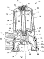
- FIG. 1 shows a filter assembly 10 according to an embodiment of the invention.
- the filter assembly 10 has particular application in a motor vehicle, e.g. for cleaning engine oil in an engine lubrication system.
- a motor vehicle e.g. for cleaning engine oil in an engine lubrication system.
- other applications are contemplated, e.g. for use in oil recovery and in the manufacture of food products.
- the filter assembly 10 comprises a housing 12 having a main body 14 and a closure member 16.
- the closure member 16 is separably attachable to the main body 14.
- the closure member 16 may be separably attachable to the main body 14 by insertion of the closure member 16 into an open end 18 of the main body 14.
- the open end 18 may be an underside end of the main body 14, i.e. an end accessible from underneath during use.
- the open end 18 may be defined, i.e. delimited, by an annular wall 18a of the main body 14.
- each of the main body 14 and the closure member 16 may comprise respective threaded portions 14a, 16a.
- the main body 14 and the closure member 16 may be separably attachable to one another by threaded engagement, i.e. the main body 14 and the closure member 16 may be screwed together and apart by a user.
- any suitable means for attaching the closure member 16 to the main body 14 may be used, e.g. each of the main body 14 and the closure member 16 may be configured to form a bayonet-type connection.
- the closure member 16 may be separable from the main body 14 by rotation, as least in part, of the closure member 16 relative to the main body 14.
- the filter assembly 10 further comprises a rotary vessel 20 and a locking member 22.
- the rotary vessel 20 comprises a rotor body 24 that is rotatable about an axis of rotation 26. (Reference herein to axial movement, axial extension, etc. is to that at least generally parallel to the axis of rotation 26. Reference herein to radial movement, radial extension, etc. is to that at least generally perpendicular to the axis of rotation 26.)
- the rotary vessel 20 and the rotor body 24 may be rotatable about the axis of rotation together as one.
- the rotary vessel 20 further comprises a lower spigot 28 and an upper spigot 30.
- Each of the lower and upper spigots 28, 30 may be coupled or integral to the rotor body 24 and extend axially therefrom along the axis of rotation 26.
- the lower and upper spigots 28, 30 are collinear.
- the lower spigot 28 may extend from a lower end of the rotor body 24 and the upper spigot 30 may extend from an upper end of the rotor body 28, i.e. opposite to the lower spigot 28.
- the rotary vessel 20 is retained within the housing 12 by attachment of the closure member 16 to the main body 14.
- the main body 14 may locate and support the upper spigot 30 within the housing 12.
- the closure member 16 may locate and support the lower spigot 28 within the housing 12.
- the main body 14 and the closure member 16 may be provided with respective bearings 34, 36 that are configured to receive the lower and upper spigots 28, 30, respectively.
- the bearings 34, 36 are shown to be multi-part components.
- the bearings 34, 36 may be any arrangement suitable for allowing the rotary vessel 20 to rotate relative to the housing 12, e.g. one or each of the bearings 34, 36 may be an aperture or recess configured to receive one of the lower and upper spigots 28, 30.
- the closure member 16 may be separable from the main body 14 to effect removal of the rotary vessel 18 from the housing 12.
- Attachment of the closure member 16 to the main body 14 may form a fluid tight volume 32, which, in use, encloses the rotary vessel 20.
- the closure member 16 may be fluidly sealable against the main body 14 by a resilient seal 38 extending along a periphery of the closure member 16.
- the resilient seal 38 may be alternatively provided on the main body 14.
- the filter assembly 10 may further comprise a fluid supply duct 50 extending through the centre of the rotor body 24, i.e. extending along the axis of rotation 26, for supplying an inner chamber 46 of the rotor body 24 with a working fluid, i.e. a fluid to cleaned/filtered, e.g. engine oil.
- the inner chamber 46 may be fluidly connected to the fluid supply duct 50 by one or more through bores 52 provided in a side walling of the fluid supply duct 50.
- the through bores 52 may extend through the side walling substantially at right angles to the axis of rotation 26.
- An inlet duct 54 may extend through the closure member 16 to supply working fluid from an inlet port 56 to the fluid supply duct 50.
- the working fluid may be supplied to the inlet port 56 at elevated pressure to flow from the inlet port 56 to the through bores 52, via both of the inlet duct 54 and the fluid supply duct 50.
- the working fluid exits the through bores 52 into the inner chamber 46 of the rotor body 24.
- the rotary vessel 20 may be self-powerable, i.e. the pressurised supply of working fluid may drive rotation of the rotor body 24.
- the rotor body 24 may further comprise a pair of diametrically opposed drive nozzles 58 fluidly connected with the inner chamber 46 of the rotor body 24.
- the drive nozzles 58 are each provided at a radial distance from the axis of rotation 26 (about which the rotor body 24 is rotatable) and configured such that the working fluid exits the inner chamber 46, through the drive nozzles 58, in a direction generally tangential to the rotor body 24.
- the tangential emission of the working fluid, at elevated pressure results in a reactive force that causes rotation of the rotor body 24 about the axis of rotation 26.
- centrifugal force causes separation of contaminant material within the working fluid.
- Separated contaminant material may accumulate within the inner chamber 46 of the rotor body 24, primarily as a cake adhering to an interior surface of the inner chamber 46 or to a liner provided therein. Fluid exiting the rotor body 24 may drain to a sump and exit the filter assembly 10 though an outlet port 44.
- the filter assembly 10 must be serviced, e.g. either to clean or replace the rotary vessel 20.
- To service the filter assembly 10 it may be necessary to remove the rotary vessel 20 from within the housing 12. Removal of the rotary vessel 20 from the within the housing 12 requires separation of the closure member 16 from the main body 14.
- the closure member 16 is rotatable, e.g. it may be unscrewed by a user, relative to the main body 14 in a first direction to effect the necessary separation.
- the first direction may be clockwise or anti-clockwise.
- rotation of the of the closure member 16 relative to the main body 14 may be induced by vibration of the filter assembly 10. Vibration may occur as a result of the rotor body 24 rotating within the housing 12.
- Such induced rotation of the closure member 16 is undesirable, as it may result in accidental separation or unsealing of the closure member 16 from the main body 14, thus causing working fluid to leak from the filter assembly 10. Leaked working fluid, which may be flammable, may pose a fire hazard.
- the undesirable rotation of the closure member 16 relative to the main body 14 may be exacerbated by the weight of the rotary vessel 20 acting downwards upon the closure member 16, as is the case in the illustrated embodiment.
- the undesirable rotation of the closure member 16 may be inhibited by the locking member 22.
- the locking member 22 is releasably engageable with at least part of the housing 12 to inhibit rotation of the closure member 16 relative to the main body 14, as is described in more detail below.
- the locking member 22 may be releasably engageable with at least part of the housing 12 by snap-fit engagement. As in the illustrated embodiment, the locking member 22 may be releasably engageable with the main body 14 by snap-fit engagement. Snap-fit engagement is advantageous as it may facilitate rapid construction, i.e. assembly, and/or servicing of the filter assembly 10, without the use of tools, and may reduce the number of loose and/or separate component parts that make up the filter assembly 10. As will be appreciated, various types of snap-fit engagement are possible, e.g. cantilever snap-fit engagement, torsional snap-fit engagement and annular snap-fit engagement. (Described herein is a non-limiting arrangement that provides a cantilever snap-fit engagement of the locking member 22 to the housing 12.)
- the locking member 22 may be releasably engageable with the closure member 16. More specifically, the locking member 22 may be releasably engageable with the closure member 16 by insertion of the locking member 22 into an open end of the closure member 16. Releasable engagement of the locking member 22 with the closure member 16 may inhibit rotation of the locking member 22 relative to the closure member 16, at least in one direction. Additionally, or alternatively, the locking member 22 may be releasably engageable with the main body 14. The locking member 22 may be releasably engageable with the main body 14 such that rotation of the locking member 22 relative to the main body 14 is inhibited, at least in one direction.
- the locking member 22 may be both inhibited from rotation relative to the main body 14 in the first direction and inhibited from rotation relative to the closure member 16 in a second direction, the second direction being opposite to the first direction. Consequently, rotation of the closure member 16 relative to the main body 14 in the first direction may be inhibited to prevent the accidental separation or unsealing of the closure member 16 from the main body 14.
- Figure 2 shows an embodiment of the locking member 22.
- the locking member 22 may comprise a first formation 60 and the closure member 16 may comprise a second formation 62, the second formation 62 being complementary to the first formation 60.
- the first formation 60 may be non-circular, e.g. polygonal.
- the first formation 60 may be an aperture extending through a portion of the locking member 22.
- a peripheral surface of the locking member 22 may achieve a form-fit with a surface of the closure member 16.
- the locking member 22 may comprise one or more radially extending ribs 48 engageable with complementary indents in the closure member 16.
- the locking member 22 may be of single piece construction.
- the locking member 22 may be moulded from a plastics material.
- the locking member 22 may comprise a body portion 40 and one or more lugs 42.
- the body portion 40 may be annular.
- the lugs 42 may extend radially from the body portion 40.
- the lugs 42 may each comprise a respective hooked portion 42a.
- the hooked portions 42a may be formed at or coupled to free ends 42a of the lugs 42, i.e. ends of the lugs 42 furthest from the body portion 40.
- the hooked portions 42a may permit each of the lugs 42 to extend around the annular wall 18a at the open end 18 of the main body 14 to engage with a respective radially extending formation 64 coupled or integral to a peripheral surface of the main body 14.
- Each of the radially extending formations 64 may extend radially from or into the peripheral surface of the main body 14.
- Each of the radially extending formations 64 may form one or more rotation inhibiting surfaces 66 (e.g. see Figure 4 ) against which a respective lug 42 abuts to inhibit rotation of closure member 16 relative to the main body 14, i.e. each of the rotation inhibiting surfaces 66 may block, i.e. interrupt, a circumferential path of the lugs 42 extending about the main body 14. This is described in more detail below.
- One or more of the rotation inhibiting surfaces 66 may be a surface substantially parallel to the axis of the axis of rotation 26.
- the lugs 42 may effect releasable engagement of the locking member 22 and main body 14, i.e. the lugs 42 may be configured to cooperate with the main body 14 to releasably engage the locking member 22 with the main body 14, such that axial movement of the locking member 22 relative the main body 14 is inhibited, at least in one direction. More specifically, the lugs 42 may abut one or more retaining surfaces 68 that are integral or coupled to the main body 14, to prevent release of the locking member 22 from engagement with the main body 14. To this end, the retaining surfaces 68 may obstruct an axial path of the lugs 42.
- Each of the radially extending formations 64 may form one or more of the retaining surfaces 68, in addition to, or instead of, one or more of the rotation inhibiting surfaces 66.
- One or more of the retaining surfaces 68 may be a surface substantially perpendicular to the axis of the axis of rotation 26.
- each of the lugs 42 may be elastically deformable, i.e. flexible/ pliable. Consequently, radial movement of the hooked portions 42a may be permitted by deformation of the lugs 42. This radial movement may effect release of the locking member 22 from engagement with the main body. This is described in more detail below.
- the locking member 22 may be of single piece construction.
- FIGS. 6 and 7 show an embodiment of the lower spigot 28.
- the lower spigot 28 may have an abutment surface 70 configured for abutment against a cooperating surface 72. Abutment of the abutment surface 70 against the cooperating surface 72 may inhibit axial movement of the rotary vessel 20 relative to the cooperating surface 72.
- the cooperating surface 72 is formed as part of the lower bearing 34. More specifically, the cooperating surface 72 may be provided as an annular surface extending around a surface of a sleeve 74, the sleeve 74 forming part of the lower bearing 34 and being rotatable therewithin.
- the lower spigot 28 may comprise one or more protrusions 76 extending radially therefrom, with the abutment surface 70 integral or coupled to the one or more protrusions 76.
- the abutment surface 70 may be provided, at least in part, by one or more recesses extending radially into the lower spigot 28. This may be in addition to, or instead of, the abutment surface 70 being provided, at least in part, by the protrusions 76. As shown on the illustrated embodiment, the abutment surface 70 may be a discontinuous surface.
- the lower spigot 28 may comprise one or more fingers 78a, 78b extending away from the rotor body 24, i.e. each finger 78a, 78b having a free end furthest from the rotor body 24.
- each of the fingers 78a, 78b may extend substantially parallel to the axis of rotation 26.
- the fingers 78a, 78b may define, i.e. delimit, or surround an opening 80, which may be an opening of the fluid supply duct 50.
- the fingers 78a, 78b may define a periphery of the spigot. The periphery may be non-circular, i.e.
- each of the fingers 78a, 78b may comprise a substantially planar surface, which may be a radially outmost surface of each respective finger 78a, 78b. As will be understood, each respective substantially planar surface may be inclined with respect to that of an adjacent finger 78a, 78b.
- the fingers 78a, 78b may abut one another, or gaps may be present between at least a number of adjacent fingers 78a, 78b.
- the sleeve 74 may have a shape that is complementary to that of the lower spigot 28. This arrangement inhibits the rotation of the lower spigot 28 within the sleeve 74, when received therein, thus reducing wear of the lower spigot 28.
- a subset of one of the one or more fingers 78a may be radially elastically deformable, i.e. flexible/pliable, by a radial force applied thereto.
- the subset of radially elastically deformable fingers 78a may comprise three fingers.
- the radially deformable fingers 78a may provide one or more elastically deformable portions of the lower spigot 28.
- the elastically deformable portions may be provided by any suitable means, e.g. by a narrowing of a portion of the lower spigot 28.
- Each of the radially elastically deformable fingers 78a may taper away from the rotor body 24, i.e.
- a subset of the fingers 78b may be substantially non-deformable, i.e. rigid, at least in the radial direction.
- the substantially non-deformable fingers 78b may provide one or more non-deformable portions of the lower spigot 28.
- the elastically deformable portions and the non-deformable portions may be alternately provided about the lower spigot 28, i.e. each of the elastically deformable portions may be spaced about the spigot intermediate the substantially non-deformable portions.
- Each of the protrusions 76 and/or the recesses may be provided on or coupled to, at least in part, one or more of each of the elastically deformable fingers 78a.
- Each of the protrusions 76 and/or the recesses may be provided at the free ends of the radially elastically deformable fingers 78a.
- each of the protrusions 76 and/or the recesses may alternatively be provided at any suitable location along the length of one or more of the radially elastically deformable fingers 78a.
- the abutment surface 70 is radially moveable by deformation of the radially elastically deformable fingers 78a.
- Such deformation may be caused by a force, acting radially inward, applied to the radially elastically deformable fingers 78a or a part thereof.
- the rotary vessel 20 may be inserted into the main body 14 of the housing 12 through the open end 18. As the rotary vessel 20 is inserted into the main body 14, it may be guided into position by guiding ribs 82 coupled or integral to an inner surface of the housing 12.
- the guiding ribs 82 may facilitate alignment of the upper spigot 30 with the upper bearing 36 as the rotary vessel 20 is positioned within the housing 12.
- One or both of the upper spigot 30 and the upper bearing 36 may be configured for frictional engagement with the other.
- the upper spigot 30 may be frictionally engaged with the upper bearing 34 to support the weight the rotary vessel 20, i.e. to inhibit the rotary vessel 20 from falling out of the housing 12 under its own weight.
- This arrangement may facilitate construction of the filter assembly 10, as the rotary vessel 20 may not need holding in position while construction of the filter assembly 10 is continued and/or completed. Conversely, however, this arrangement may impair deconstruction of the filter assembly 10, e.g. for service and/or repair, as frictional engagement of the upper spigot 30 with the upper bearing may make it difficult to extract the rotary vessel 20 from within the housing 20.
- the closure member 16 may be releasably attached to the housing 12 to form the fluid tight volume 32.
- the closure member 16 is screwed into the open end 18 of the main body 14.
- the lower spigot 28 may engage with the lower bearing 34. More specifically, in certain embodiments, the lower spigot 28 may engage with the sleeve 74 of the lower bearing 34.
- the elastically deformable portions e.g. the radially elastically deformable fingers 78a, may be caused to resiliently deform.
- each of the protrusions 76 may comprise a cam surface 84 inclined with respect to the inner wall of the sleeve 74.
- the lower spigot 28 may be fully engaged with the lower bearing 34. Consequently, the lower spigot 28 may have moved axially relative the sleeve 74 such that the protrusions 76 have moved axially beyond a portion of the inner wall of the sleeve 74 that defines, i.e. delimits, the innermost diameter of the sleeve 74.
- the projections 76 remain within the sleeve 74 and are in radial alignment with a portion of the inner wall of the sleeve 74 having a diameter substantially equal to, or greater than, the outermost diameter of the lower spigot 28.
- each of the protrusions 76 move radially outward.
- step 86 may provide the abutment surface 70.
- the step 86 may block, i.e. interrupt, an axial path of projections 76. This means that one or more of the projections 76 may abut the step 86 in the event that the closure member 16 is moved axially relative to the lower spigot 28 in a second axial direction, the second axial direction being opposite to the first axial direction.
- This arrangement may inhibit the closure member 16 from moving axially relative to the lower spigot 28 in a second axial direction. Consequently, this arrangement may inhibit the closure member 16 being separated from the rotary vessel 20, once the lower spigot 28 is fully engaged with the lower bearing 34.
- This has the advantage that when deconstructing the filter assembly 10, separation of the closure member 16 from the main body 14, e.g. by unscrewing the closure member 16 from the main body 14, may draw the rotary vessel 20 out of the housing 12.
- the lower spigot 28 may provide a connector to releasably couple the closure member 16 to the rotary vessel 20 such that the rotary vessel 20 is at least partially removable from the housing 12 by separation of the closure member 16 and the main body 14.
- the locking member 22 may be attached to the main body 14 to inhibit accidental unsealing and/or separation of the closure member 16 from the main body 14.
- the locking member 22 may be introduced into the open end of the closure member 16.
- attachment of the locking member 22 to the housing 12 may be facilitated by axial alignment of the lugs 42 with the retaining surfaces 68 prior to introduction of the locking member 22 into the open end of the closure member 22.
- the lugs 42 may deform radially outwardly as the locking member 22 is releasably attached to the main body 14.
- the radial deformation of the lugs 42 may allow the hooked portions 42a to move axially passed the respective retaining surfaces 68. Once the hooked portions 42a have moved axially passed the respective retaining surfaces 68, the inherent resilience of the lugs 42 causes them to return to their non-deformed condition, i.e. move radially inwards.
- the lugs 42 may be deformed radially outwardly by contact of the hooked portions 42a with the peripheral surface of the main body 14 and/or with the radially extending formations 64.
- the hooked portions 42a may each comprise a respective cam surface.
- the self-weight of the rotary vessel 20 may act on the closure member 16, and consequently on the locking member 22, to hold the locking member 22 in the locking position.
- the locking member 22 may be axially moveable relative to the main body 14 between the locking position and a release position.
- the release position is shown in Figures 3 and 5 .
- the locking member 22 may be rotatable relative to the main body 14 to cause release the locking member 22 from engagement with the main body 14.
- the locking member 22 is moved in the first axial direction, e.g. upwards, from the locking positon to the release position.
- a circumferential path of the lugs 42 extending about the main body 14 may be clear, i.e.
- the locking member 22 may also be axially movable relative to the closure member 16. This is because with the closure member 16 separably attached to the main body 14, the closure member 22 may not be axially moveable without rotation of the closure member 22 relative to the main body 14. Thus, the locking member 22 may be axially movable relative to the closure member 16 into and out of the locking position.
- the locking member 22 is moved from the locking position into the release position and rotated in the first direction relative to the main body 14. This action moves the lugs 42 out of axial alignment with the respective retaining surfaces 68 and allows release of the locking member 22 from the main body 14. Rotation of the locking member 22 initiates rotation of the closure member 16. Continued rotation of the closure member 16 in the first direction relative to the main body 14 detaches the closure member 16 from the main body 14, thus allowing separation of the closure member 16 from the main body. Separation of the closure member 16 from the main body 14 withdraws the rotary vessel 20 out from within the main body 12.
- the spigots 28, 30 may be provided on the housing 12 and bearings 34, 36 may be being provided on the rotary vessel 20.
- the lower spigot 28 may have a non-circular cross section that is defined, i.e. delimited, by a single part, i.e. this is not defined by the fingers 78a, 78b.
- the non-circular cross section may be a polygonal cross section, e.g. a hexagonal cross section.
- the non-circular cross section may be semi-circular cross section.
- each of the fingers 78a, 78b may comprise a curved surface, which may be the radially outermost surface of each respective finger 78a, 78b.
- the closure member 16 may be separable from the main body 14 other than by rotation of the closure member 16 relative to the main body 14.
- the locking member 22 may be releasably engageable with the closure member 14 by other means than snap-fit engagement.
- the invention is not limited to self-powerable filter assemblies, such as that which is described above.
- the filter assembly may comprise a drive means, e.g. an electric motor, which is configured to rotate the rotor body 24.
Landscapes
- Engineering & Computer Science (AREA)
- General Engineering & Computer Science (AREA)
- Mechanical Engineering (AREA)
- Chemical & Material Sciences (AREA)
- Chemical Kinetics & Catalysis (AREA)
- Centrifugal Separators (AREA)
- Closures For Containers (AREA)
Abstract
Description
- The invention relates to a rotary vessel. The invention particularly, but not necessarily, relates to a rotary vessel for a filter assembly.
- Filter assemblies are known for removing contaminant particles from lubricating oil circuits of internal combustion engines. They are also known for separating particulate matter from liquids, as well as separating liquids of different densities from one another, in a variety of industrial processes. Typically, a filter assembly comprises a housing having a rotor supported therein to spin about a spindle, the spindle providing an axis of rotation. A working fluid from which a contaminant is to be removed, e.g. engine oil, is supplied at elevated pressure along the axis of rotation to the rotor. Subsequently, the pressurised fluid is tangentially ejected from the rotor such that the rotor is caused to spin. As the working fluid flows through the spinning rotor, denser contaminants or particles are separated therefrom by centrifugal force and retained in the rotor, typically as a cake adhering to an interior surface of the rotor. Ejected fluid drains to a sump.
- As retained contaminant particles agglomerate in the rotor, it is necessary to replace or service the rotor at suitably regular intervals to ensure the continued cleaning effectiveness of the filter assembly. It is common that servicing of the rotor requires its removal from the housing. Servicing and replacement of the rotor may be time consuming and difficult due to limited available space if the filter assembly is in situ. It is an object of embodiments of the invention to at least reduce a problem associated with one or more known arrangements.
- According to a first aspect of the invention, there is provided a rotary vessel for a filter assembly, the rotary vessel comprising: a rotor body rotatable about an axis of rotation; and a spigot integral or coupled to the rotor body and extending therefrom along the axis of rotation, the spigot having an abutment surface against which, in use, a cooperating surface abuts to inhibit a movement of the rotary vessel relative to the cooperating surface and parallel to the axis of rotation. This arrangement may facilitate removal of the rotatory vessel when installed as part of a filter assembly.
- The spigot may extend from the rotor body in a first direction away from the rotor body. The abutment surface may preferably be configured such that, in use, the cooperating surface abuts to inhibit a movement of the rotary vessel relative to the cooperating surface in a direction opposite to the first direction.
- The abutment surface may at least in part be provided on or coupled to one or more protrusions extending radially from the spigot relative to the axis of rotation. Additionally, or alternatively, the abutment surface may at least in part provided on or coupled to one or more recesses or grooves extending radially into the spigot relative to the axis of rotation. The abutment surface may be a discontinuous surface extending about the spigot. In certain embodiments, the spigot may comprise one or more elastically deformable portions upon which the abutment surface is provided on or coupled to such that the abutment surface may be radially moveable relative to axis of rotation by deformation of the one or more elastically deformable portions. One or more of the elastically deformable portions may each be a radially deformable finger having a free end furthest from the rotor body. The abutment surface may at least in part be provided on or coupled to one or more of the free ends of each of the radially deformable fingers. One or more of the radially deformable fingers may each taper away from the rotor body. A plurality of the one or more elastically deformable portions may be spaced about the spigot intermediate a plurality of substantially non-deformable portions.
- Optionally, one or more of the substantially non-deformable portions may each be a substantially non-deformable finger. One or more of the elastically deformable portions may each comprise a respective cam surface, each of the elastically deformable portions being deformable by a force acting against the respective cam surface parallel to the axis of rotation. One or more of the cam surfaces may each be provided on or coupled to one or more of the protrusions. The spigot may be substantially circular in cross section. This allows the rotor to be connected to a corresponding part, for example a sleeve or other part of a bearing, in any rotative position. The spigot may also have a cross section in the shape of a polygon, for example a rectangle or square, a pentagon, a hexagon, an octagon or the like to create a form-fit connection in rotation direction, for example to a correspondingly shaped sleeve. The rotary vessel may be self-powerable in that rotor body may have a drive nozzle for emitting a pressurised working fluid therefrom to cause rotation of the rotor body by a reactive force.
- According to a second aspect of the invention, there is provided a filter assembly comprising: a housing having a main body and a closure member separably attachable to the main body to retain a rotary vessel within the housing, the closure member being separable from the main body to permit removal of the rotary vessel from the housing; and a connector to releasably couple the closure member to the rotary vessel such that the rotary vessel is at least partially removable from the housing by separation of the closure member and the main body. The closure member may be separable from the main body by a rotation of the closure member relative to the main body. The connector is a snap-fit connector. The filter assembly may comprise a rotary vessel. In certain embodiments, the rotary vessel may be that as described above, the spigot at least in part forming the connector and the closure member comprising the cooperating surface such that abutment of the abutment surface and the cooperating surface inhibits the movement of the rotary vessel relative to the cooperating surface to releasably couple the closure member to the rotary vessel. The closure member may comprise a sleeve for receiving the spigot to rotatably support the rotary vessel in the housing, the sleeve incorporating the cooperating surface. The sleeve may incorporate the cooperating surface at an open end of the sleeve. The closure member may comprise a bearing assembly, the bearing assembly incorporating the sleeve.
- According to a third aspect of the invention, there is provided a filter assembly comprising: a housing having a main body and a closure member separably attachable to the main body to retain a rotary vessel within the housing, the closure member being separable from the main body by rotation of the closure member relative to the main body to permit removal of the rotary vessel from the housing; and a locking member releasably engageable with the housing to inhibit rotation of the closure member relative to the main body. The locking member may inhibit accidental separation of the closure member from the main body. In certain embodiments, the locking member may be releasably engageable with the housing by snap-fit engagement. The locking member may be releasably engageable with the main body to inhibit rotation of the locking member relative to the main body.
- Optionally, the locking member may be axially movable relative to the main body into and out of a locking position in which rotation of the locking member relative to the housing is inhibited. The locking member may be axially moveable relative to the main body between the locking position and a release position in which the locking member may be rotatable relative to the main body to release the locking member from engagement with the main body. The locking member may be releasably engageable with the closure member to inhibit rotation of the locking member relative to the closure member. The locking member may be axially movable relative to the closure member into and out of the locking position.
- In certain embodiments, the locking member may be releasably engageable with the closure member by insertion of the locking member into an open end of the closure member. The locking member may be releasably engageable with the closure member in that the locking member achieves a form-fit with at least a portion of the closure member to inhibit rotation of the locking member relative to the closure member. The closure member may comprise a first formation having a non-circular cross-section and/or the locking member may comprise a second formation complementary to the first formation to provide at least in part the form fit. The first formation may be a non-circular aperture. The locking member may comprise a body portion. The locking member may comprise one or more lugs, which may extend radially from the body portion to effect releasable engagement of the locking member and main body.
- One or more of the lugs may each comprise a hooked portion to effect releasable engagement of the locking member and main body by abutment with one or more retaining surfaces of the main body. One or more of the lugs may each be elastically deformable such that the respective hooked portions are each radially moveable relative to the body portion by deformation of the respective lugs. Optionally, the main body may comprise one or more rotation inhibiting surfaces which, in use, one or more of the lugs may each abut to inhibit rotation of the locking member relative to the main body. In the release position, one or more of the lugs may each be deformable by rotation of the locking member relative to the main body to effect release the locking member from engagement with the main body. The locking member may be of single piece construction.
- In certain embodiments, the main body and the closure member comprise respective threaded portions may be cooperable with one another to separably attach the main body to the closure member. The closure member may be separably attachable to the main body by insertion of the closure member into an open end of the main body. The closure member may be sealable against the main body by a resilient seal extending along a periphery of the closure member. The filter assembly may comprise a rotary vessel within the housing. Optionally, the rotary vessel may be self-powerable in that rotary vessel may comprise a rotor body having a drive nozzle for emitting a pressurised working fluid therefrom to cause rotation of the rotary vessel by a reactive force.
- According to a fourth aspect of the invention, there is provided a rotary vessel for a filter assembly, the rotary vessel comprising: a rotor body rotatable about an axis of rotation; and a spigot having a non-circular cross-section integral or coupled to the rotor body and extending therefrom along the axis of rotation for engagement with a bearing. This arrangement may inhibit rotation of the spigot when engages with a bearing in a filter assembly, thus reducing wear of the spigot.
- In certain embodiments, the non-circular cross-section may be a polygonal cross section. The spigot may comprise one or more fingers each having a free end furthest from the rotor body, the fingers may at least in part define a periphery of the spigot. One or more of the fingers may each comprise a substantially planer surface at least in part defining the periphery of the spigot. One or more of the fingers may each taper away from the rotor body. A plurality of the one or more fingers may be spaced about the spigot intermediate a plurality of gaps separating adjacent fingers. The rotary vessel may be self-powerable in that the rotor body may have a drive nozzle for emitting a pressurised working fluid therefrom to cause rotation of the rotor body by a reactive force.
- According to a fifth aspect of the invention, there is provided a filter assembly comprising: a rotary vessel; a housing having a main body and a closure member separably attachable to the main body to retain the rotary vessel within the housing, the closure member being separable from the main body to permit removal of the rotary vessel from the housing; and a spigot having a non-circular cross-section integral or coupled to the rotary vessel, the spigot being engageable with a bearing to rotatably support the rotary vessel to the housing.
- According to a sixth aspect of the invention, there is provided a filter assembly comprising: a housing having a main body and a closure member separably attachable to the main body to retain a rotary vessel within the housing, the closure member being separable from the main body to permit removal of the rotary vessel from the housing; and a spigot having a non-circular cross-section integral or coupled to the housing, the spigot being engageable with a bearing to rotatably support the rotary vessel to the housing. The filter assembly may comprise a rotary vessel.
- Optionally, the closure member may be separable from the main body by a rotation of the closure member relative to the main body. The rotary vessel and the spigot may be as described above and the bearing is integral or coupled to the closure member. The bearing may comprise a sleeve with which the spigot is engageable, the sleeve being rotatable relative to the closure member and configured to inhibit rotation of the spigot relative to the sleeve.
Features described above with reference to one aspect of the invention will be understood to be compatible with those described above with reference to other aspects of the invention. - Embodiments of the invention will now be described by way of example only, with reference to the accompanying figures, in which:
-
Figure 1 is a cross sectional view of a filter assembly according to an embodiment of the invention having a locking member shown in a locking position; -
Figure 2 is a perspective view of the locking member ofFigure 1 shown separately from the filter assembly:-
Figure 3 is a further cross sectional view of the filter assembly ofFigure 1 in which the locking member is shown in a release positon. -
Figure 4 is a side view of the filter assembly ofFigure 1 in which the locking member is shown in the locking positon. -
Figure 5 is a further side view of the filter assembly ofFigure 1 in which the locking member is shown in the release positon. -
Figure 6 is an enlarged region of the cross-sectional view ofFigure 1 showing a spigot of a rotor vessel according to an embodiment of the invention; and -
Figure 7 is a perspective view of the spigot ofFigure 6 engaged with a bearing shown in cutaway to make visible the spigot.
-
-
Figure 1 shows afilter assembly 10 according to an embodiment of the invention. Thefilter assembly 10 has particular application in a motor vehicle, e.g. for cleaning engine oil in an engine lubrication system. However, other applications are contemplated, e.g. for use in oil recovery and in the manufacture of food products. - The
filter assembly 10 comprises ahousing 12 having amain body 14 and aclosure member 16. Theclosure member 16 is separably attachable to themain body 14. As in the illustrated embodiment, theclosure member 16 may be separably attachable to themain body 14 by insertion of theclosure member 16 into anopen end 18 of themain body 14. Theopen end 18 may be an underside end of themain body 14, i.e. an end accessible from underneath during use. Theopen end 18 may be defined, i.e. delimited, by anannular wall 18a of themain body 14. To effect attachment of theclosure member 16 to themain body 14, each of themain body 14 and theclosure member 16 may comprise respective threadedportions main body 14 and theclosure member 16 may be separably attachable to one another by threaded engagement, i.e. themain body 14 and theclosure member 16 may be screwed together and apart by a user. However, in alternative embodiments, any suitable means for attaching theclosure member 16 to themain body 14 may be used, e.g. each of themain body 14 and theclosure member 16 may be configured to form a bayonet-type connection. As in the illustrated embodiment, theclosure member 16 may be separable from themain body 14 by rotation, as least in part, of theclosure member 16 relative to themain body 14. - The
filter assembly 10 further comprises arotary vessel 20 and a lockingmember 22. Therotary vessel 20 comprises arotor body 24 that is rotatable about an axis ofrotation 26. (Reference herein to axial movement, axial extension, etc. is to that at least generally parallel to the axis ofrotation 26. Reference herein to radial movement, radial extension, etc. is to that at least generally perpendicular to the axis ofrotation 26.) Therotary vessel 20 and therotor body 24 may be rotatable about the axis of rotation together as one. Therotary vessel 20 further comprises alower spigot 28 and anupper spigot 30. Each of the lower andupper spigots rotor body 24 and extend axially therefrom along the axis ofrotation 26. Thus, the lower andupper spigots lower spigot 28 may extend from a lower end of therotor body 24 and theupper spigot 30 may extend from an upper end of therotor body 28, i.e. opposite to thelower spigot 28. Therotary vessel 20 is retained within thehousing 12 by attachment of theclosure member 16 to themain body 14. In certain embodiments, themain body 14 may locate and support theupper spigot 30 within thehousing 12. Additionally, or alternatively, theclosure member 16 may locate and support thelower spigot 28 within thehousing 12. To this end, themain body 14 and theclosure member 16 may be provided withrespective bearings upper spigots bearings bearings rotary vessel 20 to rotate relative to thehousing 12, e.g. one or each of thebearings upper spigots closure member 16 may be separable from themain body 14 to effect removal of therotary vessel 18 from thehousing 12. - Attachment of the
closure member 16 to themain body 14 may form a fluidtight volume 32, which, in use, encloses therotary vessel 20. To this end, theclosure member 16 may be fluidly sealable against themain body 14 by aresilient seal 38 extending along a periphery of theclosure member 16. In certain embodiments, theresilient seal 38 may be alternatively provided on themain body 14. - The
filter assembly 10 may further comprise afluid supply duct 50 extending through the centre of therotor body 24, i.e. extending along the axis ofrotation 26, for supplying aninner chamber 46 of therotor body 24 with a working fluid, i.e. a fluid to cleaned/filtered, e.g. engine oil. Theinner chamber 46 may be fluidly connected to thefluid supply duct 50 by one or more throughbores 52 provided in a side walling of thefluid supply duct 50. The through bores 52 may extend through the side walling substantially at right angles to the axis ofrotation 26. Aninlet duct 54 may extend through theclosure member 16 to supply working fluid from aninlet port 56 to thefluid supply duct 50. In use, the working fluid may be supplied to theinlet port 56 at elevated pressure to flow from theinlet port 56 to the through bores 52, via both of theinlet duct 54 and thefluid supply duct 50. The working fluid exits the through bores 52 into theinner chamber 46 of therotor body 24. As in the illustrated embodiment, therotary vessel 20 may be self-powerable, i.e. the pressurised supply of working fluid may drive rotation of therotor body 24. To this end, therotor body 24 may further comprise a pair of diametricallyopposed drive nozzles 58 fluidly connected with theinner chamber 46 of therotor body 24. The drive nozzles 58 are each provided at a radial distance from the axis of rotation 26 (about which therotor body 24 is rotatable) and configured such that the working fluid exits theinner chamber 46, through thedrive nozzles 58, in a direction generally tangential to therotor body 24. As will be understood, the tangential emission of the working fluid, at elevated pressure, results in a reactive force that causes rotation of therotor body 24 about the axis ofrotation 26. - As working fluid flows through the spinning
rotary vessel 20, centrifugal force causes separation of contaminant material within the working fluid. Separated contaminant material may accumulate within theinner chamber 46 of therotor body 24, primarily as a cake adhering to an interior surface of theinner chamber 46 or to a liner provided therein. Fluid exiting therotor body 24 may drain to a sump and exit thefilter assembly 10 though anoutlet port 44. As contaminant accumulates within theinner chamber 46, thefilter assembly 10 must be serviced, e.g. either to clean or replace therotary vessel 20. To service thefilter assembly 10, it may be necessary to remove therotary vessel 20 from within thehousing 12. Removal of therotary vessel 20 from the within thehousing 12 requires separation of theclosure member 16 from themain body 14. In the illustrated embodiment, theclosure member 16 is rotatable, e.g. it may be unscrewed by a user, relative to themain body 14 in a first direction to effect the necessary separation. The first direction may be clockwise or anti-clockwise. - Problematically, rotation of the of the
closure member 16 relative to themain body 14 may be induced by vibration of thefilter assembly 10. Vibration may occur as a result of therotor body 24 rotating within thehousing 12. Such induced rotation of theclosure member 16 is undesirable, as it may result in accidental separation or unsealing of theclosure member 16 from themain body 14, thus causing working fluid to leak from thefilter assembly 10. Leaked working fluid, which may be flammable, may pose a fire hazard. Moreover, the undesirable rotation of theclosure member 16 relative to themain body 14 may be exacerbated by the weight of therotary vessel 20 acting downwards upon theclosure member 16, as is the case in the illustrated embodiment. The undesirable rotation of theclosure member 16 may be inhibited by the lockingmember 22. To this end, the lockingmember 22 is releasably engageable with at least part of thehousing 12 to inhibit rotation of theclosure member 16 relative to themain body 14, as is described in more detail below. - The locking
member 22 may be releasably engageable with at least part of thehousing 12 by snap-fit engagement. As in the illustrated embodiment, the lockingmember 22 may be releasably engageable with themain body 14 by snap-fit engagement. Snap-fit engagement is advantageous as it may facilitate rapid construction, i.e. assembly, and/or servicing of thefilter assembly 10, without the use of tools, and may reduce the number of loose and/or separate component parts that make up thefilter assembly 10. As will be appreciated, various types of snap-fit engagement are possible, e.g. cantilever snap-fit engagement, torsional snap-fit engagement and annular snap-fit engagement. (Described herein is a non-limiting arrangement that provides a cantilever snap-fit engagement of the lockingmember 22 to thehousing 12.) - As shown in the accompanying figures, the locking
member 22 may be releasably engageable with theclosure member 16. More specifically, the lockingmember 22 may be releasably engageable with theclosure member 16 by insertion of the lockingmember 22 into an open end of theclosure member 16. Releasable engagement of the lockingmember 22 with theclosure member 16 may inhibit rotation of the lockingmember 22 relative to theclosure member 16, at least in one direction. Additionally, or alternatively, the lockingmember 22 may be releasably engageable with themain body 14. The lockingmember 22 may be releasably engageable with themain body 14 such that rotation of the lockingmember 22 relative to themain body 14 is inhibited, at least in one direction. Thus, with the lockingmember 22 simultaneously engaged with both theclosure member 16 and themain body 14, the lockingmember 22 may be both inhibited from rotation relative to themain body 14 in the first direction and inhibited from rotation relative to theclosure member 16 in a second direction, the second direction being opposite to the first direction. Consequently, rotation of theclosure member 16 relative to themain body 14 in the first direction may be inhibited to prevent the accidental separation or unsealing of theclosure member 16 from themain body 14. -
Figure 2 shows an embodiment of the lockingmember 22. To effect releasable engagement of the lockingmember 22 with theclosure member 16, at least a portion of the lockingmember 22 may achieve a form-fit with a portion of theclosure member 16, i.e. contours and/or shapes of the lockingmember 22 may allow for snug engagement of the lockingmember 22 with theclosure member 16. To this end, the lockingmember 22 may comprise afirst formation 60 and theclosure member 16 may comprise asecond formation 62, thesecond formation 62 being complementary to thefirst formation 60. As will be understood, it is the form-fit of the lockingmember 22 with theclosure member 16 which may inhibit relative rotation of the two parts. As shown in the illustrated embodiment, thefirst formation 60 may be non-circular, e.g. polygonal. Thefirst formation 60 may be an aperture extending through a portion of the lockingmember 22. In certain embodiments, a peripheral surface of the lockingmember 22 may achieve a form-fit with a surface of theclosure member 16. Additionally, or alternatively, the lockingmember 22 may comprise one or more radially extendingribs 48 engageable with complementary indents in theclosure member 16. As shown in the accompanying figures, the lockingmember 22 may be of single piece construction. The lockingmember 22 may be moulded from a plastics material. - As shown in the accompanying figures, the locking
member 22 may comprise abody portion 40 and one or more lugs 42. Thebody portion 40 may be annular. Thelugs 42 may extend radially from thebody portion 40. Thelugs 42 may each comprise a respectivehooked portion 42a. Thehooked portions 42a may be formed at or coupled tofree ends 42a of thelugs 42, i.e. ends of thelugs 42 furthest from thebody portion 40. Thehooked portions 42a may permit each of thelugs 42 to extend around theannular wall 18a at theopen end 18 of themain body 14 to engage with a respectiveradially extending formation 64 coupled or integral to a peripheral surface of themain body 14. Each of theradially extending formations 64 may extend radially from or into the peripheral surface of themain body 14. Each of theradially extending formations 64 may form one or more rotation inhibiting surfaces 66 (e.g. seeFigure 4 ) against which arespective lug 42 abuts to inhibit rotation ofclosure member 16 relative to themain body 14, i.e. each of therotation inhibiting surfaces 66 may block, i.e. interrupt, a circumferential path of thelugs 42 extending about themain body 14. This is described in more detail below. One or more of therotation inhibiting surfaces 66 may be a surface substantially parallel to the axis of the axis ofrotation 26. - Additionally, or alternatively, the
lugs 42 may effect releasable engagement of the lockingmember 22 andmain body 14, i.e. thelugs 42 may be configured to cooperate with themain body 14 to releasably engage the lockingmember 22 with themain body 14, such that axial movement of the lockingmember 22 relative themain body 14 is inhibited, at least in one direction. More specifically, thelugs 42 may abut one or more retaining surfaces 68 that are integral or coupled to themain body 14, to prevent release of the lockingmember 22 from engagement with themain body 14. To this end, the retaining surfaces 68 may obstruct an axial path of thelugs 42. Each of theradially extending formations 64 may form one or more of the retaining surfaces 68, in addition to, or instead of, one or more of the rotation inhibiting surfaces 66. One or more of the retaining surfaces 68 may be a surface substantially perpendicular to the axis of the axis ofrotation 26. - At least a portion of each of the
lugs 42 may be elastically deformable, i.e. flexible/ pliable. Consequently, radial movement of thehooked portions 42a may be permitted by deformation of thelugs 42. This radial movement may effect release of the lockingmember 22 from engagement with the main body. This is described in more detail below. As shown in the illustrated embodiment, the lockingmember 22 may be of single piece construction. -
Figures 6 and 7 show an embodiment of thelower spigot 28. Thelower spigot 28 may have anabutment surface 70 configured for abutment against a cooperatingsurface 72. Abutment of theabutment surface 70 against the cooperatingsurface 72 may inhibit axial movement of therotary vessel 20 relative to the cooperatingsurface 72. In the illustrated embodiment, the cooperatingsurface 72 is formed as part of thelower bearing 34. More specifically, the cooperatingsurface 72 may be provided as an annular surface extending around a surface of asleeve 74, thesleeve 74 forming part of thelower bearing 34 and being rotatable therewithin. Consequently, as thelower bearing 34 may be provided as part of theclosure member 16, abutment of theabutment surface 70 against the cooperatingsurface 72 may inhibit an axial movement of therotary vessel 20 relative to theclosure member 16. Thus, with thelower spigot 28 engaged with the lower bearing, separation of theclosure member 16 from themain body 14 may draw therotary vessel 20 out from within thehousing 12. Thelower spigot 28 may comprise one ormore protrusions 76 extending radially therefrom, with theabutment surface 70 integral or coupled to the one ormore protrusions 76. However, in certain embodiments, theabutment surface 70 may be provided, at least in part, by one or more recesses extending radially into thelower spigot 28. This may be in addition to, or instead of, theabutment surface 70 being provided, at least in part, by theprotrusions 76. As shown on the illustrated embodiment, theabutment surface 70 may be a discontinuous surface. - In certain embodiments, the
lower spigot 28 may comprise one ormore fingers rotor body 24, i.e. eachfinger rotor body 24. As shown in the accompanying figures, each of thefingers rotation 26. Together, thefingers opening 80, which may be an opening of thefluid supply duct 50. Additionally, or alternatively, thefingers lower spigot 28 may have a non-circular cross section. To this end, each of thefingers respective finger adjacent finger fingers adjacent fingers lower spigot 28 of non-circular cross section, thesleeve 74 may have a shape that is complementary to that of thelower spigot 28. This arrangement inhibits the rotation of thelower spigot 28 within thesleeve 74, when received therein, thus reducing wear of thelower spigot 28. - A subset of one of the one or
more fingers 78a may be radially elastically deformable, i.e. flexible/pliable, by a radial force applied thereto. The subset of radially elasticallydeformable fingers 78a may comprise three fingers. The radiallydeformable fingers 78a may provide one or more elastically deformable portions of thelower spigot 28. However, in alternative embodiments, the elastically deformable portions may be provided by any suitable means, e.g. by a narrowing of a portion of thelower spigot 28. Each of the radially elasticallydeformable fingers 78a may taper away from therotor body 24, i.e. narrow in the radial direction away from therotor body 24, and this may provide the required elastic deformability. Additionally, or alternatively, a subset of thefingers 78b may be substantially non-deformable, i.e. rigid, at least in the radial direction. Thus, the substantiallynon-deformable fingers 78b may provide one or more non-deformable portions of thelower spigot 28. The elastically deformable portions and the non-deformable portions may be alternately provided about thelower spigot 28, i.e. each of the elastically deformable portions may be spaced about the spigot intermediate the substantially non-deformable portions. - Each of the
protrusions 76 and/or the recesses may be provided on or coupled to, at least in part, one or more of each of the elasticallydeformable fingers 78a. Each of theprotrusions 76 and/or the recesses may be provided at the free ends of the radially elasticallydeformable fingers 78a. However, each of theprotrusions 76 and/or the recesses may alternatively be provided at any suitable location along the length of one or more of the radially elasticallydeformable fingers 78a. Thus, as will be understood, theabutment surface 70 is radially moveable by deformation of the radially elasticallydeformable fingers 78a. Such deformation may be caused by a force, acting radially inward, applied to the radially elasticallydeformable fingers 78a or a part thereof.
In constructing thefilter assembly 10, therotary vessel 20 may be inserted into themain body 14 of thehousing 12 through theopen end 18. As therotary vessel 20 is inserted into themain body 14, it may be guided into position by guidingribs 82 coupled or integral to an inner surface of thehousing 12. The guidingribs 82 may facilitate alignment of theupper spigot 30 with theupper bearing 36 as therotary vessel 20 is positioned within thehousing 12. One or both of theupper spigot 30 and theupper bearing 36 may be configured for frictional engagement with the other. With therotary vessel 20 fully inserted into thehousing 12, theupper spigot 30 may be frictionally engaged with theupper bearing 34 to support the weight therotary vessel 20, i.e. to inhibit therotary vessel 20 from falling out of thehousing 12 under its own weight. This arrangement may facilitate construction of thefilter assembly 10, as therotary vessel 20 may not need holding in position while construction of thefilter assembly 10 is continued and/or completed. Conversely, however, this arrangement may impair deconstruction of thefilter assembly 10, e.g. for service and/or repair, as frictional engagement of theupper spigot 30 with the upper bearing may make it difficult to extract therotary vessel 20 from within thehousing 20. - With the
rotary vessel 20 received within themain body 14 of thehousing 12, theclosure member 16 may be releasably attached to thehousing 12 to form the fluidtight volume 32. In the illustrated embodiment, theclosure member 16 is screwed into theopen end 18 of themain body 14. As theclosure member 16 is attached to themain body 14, thelower spigot 28 may engage with thelower bearing 34. More specifically, in certain embodiments, thelower spigot 28 may engage with thesleeve 74 of thelower bearing 34. Upon initial, i.e. partial, engagement of thelower spigot 28 with thelower bearing 34, the elastically deformable portions, e.g. the radially elasticallydeformable fingers 78a, may be caused to resiliently deform. In the illustrated embodiment, as thelower spigot 28 engages with thelower bearing 34, theprotrusions 76 of the radially elasticallydeformable fingers 78a contact an inner wall of thesleeve 74 to urge, i.e. deform, the radially elasticallydeformable fingers 78a radially inwards. This is because an outermost diameter of thelower spigot 28, which includes theprotrusions 76, is larger than an innermost diameter of thesleeve 74. To facilitate the engagement of thelower spigot 28 withlower bearing 34, each of theprotrusions 76 may comprise acam surface 84 inclined with respect to the inner wall of thesleeve 74. Thus, as thelower spigot 28 is introduced to thesleeve 74, a force will act in the axial direction again each of the cam surfaces 84 to initiate the radially inward deflection of theprotrusions 76 and the radially elasticallydeformable fingers 78a. The radially inward deflection of the radially elasticallydeformable fingers 78a allows for theclosure member 16 to move axially relative to thelower spigot 28 in a first axial direction. - Once the
closure member 16 is releasably attached to thehousing 12, thelower spigot 28 may be fully engaged with thelower bearing 34. Consequently, thelower spigot 28 may have moved axially relative thesleeve 74 such that theprotrusions 76 have moved axially beyond a portion of the inner wall of thesleeve 74 that defines, i.e. delimits, the innermost diameter of thesleeve 74. In the illustrated embodiment, theprojections 76 remain within thesleeve 74 and are in radial alignment with a portion of the inner wall of thesleeve 74 having a diameter substantially equal to, or greater than, the outermost diameter of thelower spigot 28. The inherent resilience of the radially elasticallydeformable fingers 78a allows them to return to their non-deformed condition when radially aligned with the portion of thesleeve 74 having a diameter substantially equal to, or greater than, the outermost diameter of thelower spigot 28. Thus, each of theprotrusions 76 move radially outward. - The transition between the portions of inner wall the
sleeve 74 of different diameters forms astep 86. As in the illustrated embodiment, thestep 86 may provide theabutment surface 70. Thus, with thelower spigot 28 fully engaged with thelower bearing 34 and the radially elasticallydeformable fingers 78a returned to their non-deformed condition, thestep 86 may block, i.e. interrupt, an axial path ofprojections 76. This means that one or more of theprojections 76 may abut thestep 86 in the event that theclosure member 16 is moved axially relative to thelower spigot 28 in a second axial direction, the second axial direction being opposite to the first axial direction. This arrangement may inhibit theclosure member 16 from moving axially relative to thelower spigot 28 in a second axial direction. Consequently, this arrangement may inhibit theclosure member 16 being separated from therotary vessel 20, once thelower spigot 28 is fully engaged with thelower bearing 34. This has the advantage that when deconstructing thefilter assembly 10, separation of theclosure member 16 from themain body 14, e.g. by unscrewing theclosure member 16 from themain body 14, may draw therotary vessel 20 out of thehousing 12. Thus, thelower spigot 28 may provide a connector to releasably couple theclosure member 16 to therotary vessel 20 such that therotary vessel 20 is at least partially removable from thehousing 12 by separation of theclosure member 16 and themain body 14. With theclosure member 16 releasably attached to thehousing 12, the lockingmember 22 may be attached to themain body 14 to inhibit accidental unsealing and/or separation of theclosure member 16 from themain body 14. To releasably attach the lockingmember 22 to thehousing 12, the lockingmember 22 may be introduced into the open end of theclosure member 16. In the illustrated embodiment, attachment of the lockingmember 22 to thehousing 12 may be facilitated by axial alignment of thelugs 42 with the retaining surfaces 68 prior to introduction of the lockingmember 22 into the open end of theclosure member 22. Moreover, thelugs 42 may deform radially outwardly as the lockingmember 22 is releasably attached to themain body 14. The radial deformation of thelugs 42 may allow thehooked portions 42a to move axially passed the respective retaining surfaces 68. Once thehooked portions 42a have moved axially passed the respective retaining surfaces 68, the inherent resilience of thelugs 42 causes them to return to their non-deformed condition, i.e. move radially inwards. Thelugs 42 may be deformed radially outwardly by contact of thehooked portions 42a with the peripheral surface of themain body 14 and/or with theradially extending formations 64. To facilitate the radially outward deformation of thelugs 42, thehooked portions 42a may each comprise a respective cam surface. - With the locking
member 22 releasably engaged with themain body 14, axial movement of the lockingmember 22 may be inhibited by abutment of each of thehooked portions 42a against one or more respective retaining surfaces 68. Consequently, release of the lockingmember 22 from engagement with themain body 14 may be inhibited, thus ensuring the lockingmember 22 remains engaged with thehousing 12 in use. However, with the lockingmember 22 releasably engaged with themain body 14, the lockingmember 22 may be axially movable relative to themain body 14 into and out of a locking position. The locking positon is shown inFigures 1 and4 , in which rotation of the lockingmember 22 relative to thehousing 12 is inhibited, by abutment of thelugs 42 with the rotation inhibiting surfaces 66. The self-weight of therotary vessel 20 may act on theclosure member 16, and consequently on the lockingmember 22, to hold the lockingmember 22 in the locking position. In certain embodiments, the lockingmember 22 may be axially moveable relative to themain body 14 between the locking position and a release position. The release position is shown inFigures 3 and5 . In the release position, the lockingmember 22 may be rotatable relative to themain body 14 to cause release the lockingmember 22 from engagement with themain body 14. In the illustrated embodiment, the lockingmember 22 is moved in the first axial direction, e.g. upwards, from the locking positon to the release position. In the release position, a circumferential path of thelugs 42 extending about themain body 14 may be clear, i.e. uninterrupted, by therotation inhibiting surfaces 66, at least it one direction, e.g. in the first direction. As in the illustrated embodiment, the lockingmember 22 may also be axially movable relative to theclosure member 16. This is because with theclosure member 16 separably attached to themain body 14, theclosure member 22 may not be axially moveable without rotation of theclosure member 22 relative to themain body 14. Thus, the lockingmember 22 may be axially movable relative to theclosure member 16 into and out of the locking position. - Thus, in the illustrated embodiment, to remove the
rotary vessel 20 from thehousing 12, e.g. for cleaning/maintenance, the lockingmember 22 is moved from the locking position into the release position and rotated in the first direction relative to themain body 14. This action moves thelugs 42 out of axial alignment with the respective retaining surfaces 68 and allows release of the lockingmember 22 from themain body 14. Rotation of the lockingmember 22 initiates rotation of theclosure member 16. Continued rotation of theclosure member 16 in the first direction relative to themain body 14 detaches theclosure member 16 from themain body 14, thus allowing separation of theclosure member 16 from the main body. Separation of theclosure member 16 from themain body 14 withdraws therotary vessel 20 out from within themain body 12. - The invention is not restricted to the details of any foregoing embodiments. For example, certain embodiments of the invention may not include the locking
member 22. The invention extends to any novel one, or any novel combination, of the features disclosed in this specification (including any accompanying claims and drawings) or to any novel one, or any novel combination, of the steps of any method or process so disclosed. The claims should not be construed to cover merely the foregoing embodiments, but also any embodiments which fall within the scope of the claims. - In certain embodiments, features described above with reference to the
lower spigot 28 and thelower bearing 34 are equally applicable to theupper spigot 30 and theupper bearing 36, respectively. Moreover, thespigots housing 12 andbearings rotary vessel 20. Thelower spigot 28 may have a non-circular cross section that is defined, i.e. delimited, by a single part, i.e. this is not defined by thefingers lower spigot 28 may be circular in cross section. To this end, each of thefingers respective finger - In certain embodiments, the
closure member 16 may be separable from themain body 14 other than by rotation of theclosure member 16 relative to themain body 14. The lockingmember 22 may be releasably engageable with theclosure member 14 by other means than snap-fit engagement. Further, the invention is not limited to self-powerable filter assemblies, such as that which is described above. In certain embodiments, the filter assembly may comprise a drive means, e.g. an electric motor, which is configured to rotate therotor body 24. - All of the features disclosed in this specification (including any accompanying claims and drawings) and/or all of the steps of any method or process so disclosed, may be combined in any combination, except combinations where at least some of such features and/or steps are mutually exclusive.
- Each feature disclosed in this specification (including any accompanying claims and drawings), may be replaced by alternative features serving the same, equivalent or similar purpose, unless expressly stated otherwise. Thus, unless expressly stated otherwise, each feature disclosed is one example only of a generic series of equivalent or similar features.
Claims (18)
- A rotary vessel for a filter assembly, the rotary vessel comprising:a rotor body rotatable about an axis of rotation; anda spigot integral or coupled to the rotor body and extending therefrom along the axis of rotation, the spigot having an abutment surface against which, in use, a cooperating surface abuts to inhibit a movement of the rotary vessel relative to the cooperating surface and parallel to the axis of rotation.
- A rotary vessel according to claim 1, wherein the spigot extends from the rotor body in a first direction and wherein the abutment surface is configured such that, in use, the cooperating surface abuts against the abutment surface to inhibit a movement of the rotary vessel in a direction opposite to the first direction.
- A rotary vessel according to claim 1 or 2, wherein the abutment surface is at least in part provided on or coupled to one or more protrusions extending radially from the spigot relative to the axis of rotation.
- A rotary vessel according to any preceding claim, wherein the abutment surface is at least in part provided on or coupled to one or more recesses or grooves extending radially into the spigot relative to the axis of rotation.
- A rotary vessel according to any preceding claim, wherein the abutment surface is a discontinuous surface extending about the spigot.
- A rotary vessel according to any preceding claim, wherein the spigot comprises one or more elastically deformable portions upon which the abutment surface is provided on or coupled to such that the abutment surface is radially moveable relative to axis of rotation by deformation of the one or more elastically deformable portions.
- A rotary vessel according to claim 6, wherein one or more of the elastically deformable portions are each a radially deformable finger having a free end furthest from the rotor body.
- A rotary vessel according to claim 7, wherein the abutment surface is at least in part provided on or coupled to one or more of the free ends of each of the radially deformable fingers.
- A rotary vessel according to claim 7 or 8, wherein one or more of the radially deformable fingers each taper away from the rotor body.
- A rotary vessel according to any of claims 6 to 9, wherein a plurality of the one or more elastically deformable portions are spaced about the spigot intermediate a plurality of substantially non-deformable portions.
- A rotary vessel according to claim 10, wherein one or more of the substantially non-deformable portions are each a substantially non-deformable finger.
- A rotary vessel according to any of claims 6 to 11, wherein one or more of the elastically deformable portions each comprise a respective cam surface, each of the elastically deformable portions being deformable by a force acting against the respective cam surface parallel to the axis of rotation.
- A rotary vessel according to claim 12 when dependent on claim 3, wherein one or more of the cam surfaces are each provided on or coupled to one or more of the protrusions.
- A rotary vessel according to any preceding claim, wherein the rotary vessel is self-powerable in that the rotor body has a drive nozzle for emitting a pressurised working fluid therefrom to cause rotation of the rotor body by a reactive force.
- A filter assembly comprising:a rotary vessel according to any preceding claim;a housing having a main body and a closure member separably attachable to the main body to retain the rotary vessel within the housing, the closure member being separable from the main body to permit removal of the rotary vessel from the housing preferably by a rotation of the closure member relative to the main body; anda connector, preferably a snap-fit connector, to releasably couple the closure member to the rotary vessel such that the rotary vessel is at least partially removable from the housing by separation of the closure member and the main body.
- A filter assembly according to claim 15, the spigot at least in part forming the connector and the closure member comprising the cooperating surface such that abutment of the abutment surface and the cooperating surface inhibits the movement of the rotary vessel relative to the cooperating surface to releasably couple the closure member to the rotary vessel.
- A filter assembly according to claim 16, wherein the closure member comprises a sleeve for receiving the spigot to rotatably support the rotary vessel in the housing, the sleeve incorporating the cooperating surface, the sleeve preferably incorporating the cooperating surface at an open end of the sleeve.
- A filter assembly according to claim 17, wherein the closure member comprises a bearing assembly, the bearing assembly incorporating the sleeve.
Applications Claiming Priority (1)
| Application Number | Priority Date | Filing Date | Title |
|---|---|---|---|
| GB1708929.3A GB2563217A (en) | 2017-06-05 | 2017-06-05 | Rotary vessel |
Publications (2)
| Publication Number | Publication Date |
|---|---|
| EP3412364A1 true EP3412364A1 (en) | 2018-12-12 |
| EP3412364B1 EP3412364B1 (en) | 2021-08-11 |
Family
ID=59349779
Family Applications (1)
| Application Number | Title | Priority Date | Filing Date |
|---|---|---|---|
| EP18171140.9A Active EP3412364B1 (en) | 2017-06-05 | 2018-05-08 | Rotary vessel and filter assembly comprising a rotary vessel |
Country Status (4)
| Country | Link |
|---|---|
| US (1) | US11247151B2 (en) |
| EP (1) | EP3412364B1 (en) |
| CN (1) | CN108979788B (en) |
| GB (1) | GB2563217A (en) |
Families Citing this family (1)
| Publication number | Priority date | Publication date | Assignee | Title |
|---|---|---|---|---|
| GB2584483B (en) * | 2019-06-06 | 2023-04-05 | Mann & Hummel Gmbh | Filter sub-assembly |
Citations (3)
| Publication number | Priority date | Publication date | Assignee | Title |
|---|---|---|---|---|
| DE20100362U1 (en) * | 2000-06-20 | 2001-10-31 | Ing. Walter Hengst GmbH & Co. KG, 48147 Münster | centrifuge |
| DE10305960A1 (en) * | 2002-02-14 | 2003-08-28 | Fleetguard Quimper | filter unit |
| DE202004004215U1 (en) * | 2004-03-17 | 2005-07-28 | Hengst Gmbh & Co.Kg | Free jet centrifuge for cleaning lubricating oil in internal combustion engine, has rotor with nozzle and drive and dust collecting parts that are respectively subjected to their own lubricating oil stream |
Family Cites Families (5)
| Publication number | Priority date | Publication date | Assignee | Title |
|---|---|---|---|---|
| GB2478578A (en) * | 2010-03-11 | 2011-09-14 | Mann & Hummel Gmbh | Centrifugal separator with protected bearing |
| KR20120062032A (en) * | 2010-07-31 | 2012-06-14 | 홍종호 | Centrifugal dust removing device |
| CN103157502B (en) | 2011-12-19 | 2015-04-15 | 中国科学院大连化学物理研究所 | Catalyst of preparing ethylene and propylene by carbinol and / or dimethyl ether, preparing method and application thereof |
| CN202933573U (en) * | 2012-07-11 | 2013-05-15 | 深圳普鲁士特空压系统有限公司 | Centrifugal type filter and rotor thereof |
| GB2517504B (en) * | 2013-08-23 | 2016-02-17 | Mann & Hummel Gmbh | Filtration Apparatus |
-
2017
- 2017-06-05 GB GB1708929.3A patent/GB2563217A/en not_active Withdrawn
-
2018
- 2018-05-08 EP EP18171140.9A patent/EP3412364B1/en active Active
- 2018-06-05 CN CN201810570218.9A patent/CN108979788B/en active Active
- 2018-06-05 US US15/997,800 patent/US11247151B2/en active Active
Patent Citations (3)
| Publication number | Priority date | Publication date | Assignee | Title |
|---|---|---|---|---|
| DE20100362U1 (en) * | 2000-06-20 | 2001-10-31 | Ing. Walter Hengst GmbH & Co. KG, 48147 Münster | centrifuge |
| DE10305960A1 (en) * | 2002-02-14 | 2003-08-28 | Fleetguard Quimper | filter unit |
| DE202004004215U1 (en) * | 2004-03-17 | 2005-07-28 | Hengst Gmbh & Co.Kg | Free jet centrifuge for cleaning lubricating oil in internal combustion engine, has rotor with nozzle and drive and dust collecting parts that are respectively subjected to their own lubricating oil stream |
Also Published As
| Publication number | Publication date |
|---|---|
| US11247151B2 (en) | 2022-02-15 |
| GB201708929D0 (en) | 2017-07-19 |
| US20180345183A1 (en) | 2018-12-06 |
| GB2563217A (en) | 2018-12-12 |
| EP3412364B1 (en) | 2021-08-11 |
| CN108979788A (en) | 2018-12-11 |
| CN108979788B (en) | 2024-12-24 |
Similar Documents
| Publication | Publication Date | Title |
|---|---|---|
| EP3034147B1 (en) | Oil filter assembly having rotation type drain pin | |
| EP3003533B1 (en) | Air filter with improved performance or positioning | |
| EP4400194A2 (en) | A spin-on fluid treatment device and methods | |
| EP3412365B1 (en) | Rotary vessel and filter assembly comprising a rotary vessel | |
| WO2017041205A1 (en) | Liner with seal for rotor of centrifugal separator | |
| US20250010226A1 (en) | Rotary vessel with a releasable locking device for a filter assembly | |
| EP3412364B1 (en) | Rotary vessel and filter assembly comprising a rotary vessel | |
| EP2357039B1 (en) | Centrifugal separator with snap fit separation cone | |
| US10981094B2 (en) | Filter assembly with a pressure actuated valve assembly that permits air flow into a rotary vessel | |
| GB2563216A (en) | Filter assembly | |
| EP3495030B1 (en) | Liner for a filter sub-assembly | |
| WO2017080606A1 (en) | Oil filter assembly having rotation type drain pin | |
| US11766680B2 (en) | Filter sub-assembly | |
| EP3495031B1 (en) | Liner for a filter sub-assembly | |
| GB2569166A (en) | Liner for a filter sub-assembly | |
| CN107096649A (en) | Whizzer with letdown tank | |
| HK1189189A1 (en) | Canister filter system with drain that cooperates with filter element |
Legal Events
| Date | Code | Title | Description |
|---|---|---|---|
| PUAI | Public reference made under article 153(3) epc to a published international application that has entered the european phase |
Free format text: ORIGINAL CODE: 0009012 |
|
| STAA | Information on the status of an ep patent application or granted ep patent |
Free format text: STATUS: THE APPLICATION HAS BEEN PUBLISHED |
|
| AK | Designated contracting states |
Kind code of ref document: A1 Designated state(s): AL AT BE BG CH CY CZ DE DK EE ES FI FR GB GR HR HU IE IS IT LI LT LU LV MC MK MT NL NO PL PT RO RS SE SI SK SM TR |
|
| AX | Request for extension of the european patent |
Extension state: BA ME |
|
| STAA | Information on the status of an ep patent application or granted ep patent |
Free format text: STATUS: REQUEST FOR EXAMINATION WAS MADE |
|
| 17P | Request for examination filed |
Effective date: 20190529 |
|
| RBV | Designated contracting states (corrected) |
Designated state(s): AL AT BE BG CH CY CZ DE DK EE ES FI FR GB GR HR HU IE IS IT LI LT LU LV MC MK MT NL NO PL PT RO RS SE SI SK SM TR |
|
| STAA | Information on the status of an ep patent application or granted ep patent |
Free format text: STATUS: EXAMINATION IS IN PROGRESS |
|
| 17Q | First examination report despatched |
Effective date: 20200527 |
|
| RIC1 | Information provided on ipc code assigned before grant |
Ipc: B04B 5/00 20060101AFI20210202BHEP Ipc: B04B 9/12 20060101ALI20210202BHEP Ipc: F16N 39/06 20060101ALI20210202BHEP Ipc: F01M 11/03 20060101ALI20210202BHEP |
|
| GRAP | Despatch of communication of intention to grant a patent |
Free format text: ORIGINAL CODE: EPIDOSNIGR1 |
|
| STAA | Information on the status of an ep patent application or granted ep patent |
Free format text: STATUS: GRANT OF PATENT IS INTENDED |
|
| INTG | Intention to grant announced |
Effective date: 20210316 |
|
| RAP3 | Party data changed (applicant data changed or rights of an application transferred) |
Owner name: MANN+HUMMEL GMBH |
|
| GRAJ | Information related to disapproval of communication of intention to grant by the applicant or resumption of examination proceedings by the epo deleted |
Free format text: ORIGINAL CODE: EPIDOSDIGR1 |
|
| STAA | Information on the status of an ep patent application or granted ep patent |
Free format text: STATUS: EXAMINATION IS IN PROGRESS |
|
| GRAP | Despatch of communication of intention to grant a patent |
Free format text: ORIGINAL CODE: EPIDOSNIGR1 |
|
| STAA | Information on the status of an ep patent application or granted ep patent |
Free format text: STATUS: GRANT OF PATENT IS INTENDED |
|
| GRAS | Grant fee paid |
Free format text: ORIGINAL CODE: EPIDOSNIGR3 |
|
| GRAA | (expected) grant |
Free format text: ORIGINAL CODE: 0009210 |
|
| STAA | Information on the status of an ep patent application or granted ep patent |
Free format text: STATUS: THE PATENT HAS BEEN GRANTED |
|
| INTC | Intention to grant announced (deleted) | ||
| RIN1 | Information on inventor provided before grant (corrected) |
Inventor name: FELL, ANTHONY W. Inventor name: ROUSE, ANGUS Inventor name: NASH, ROBIN Inventor name: MARQUES, TIAGO |
|
| INTG | Intention to grant announced |
Effective date: 20210705 |
|
| AK | Designated contracting states |
Kind code of ref document: B1 Designated state(s): AL AT BE BG CH CY CZ DE DK EE ES FI FR GB GR HR HU IE IS IT LI LT LU LV MC MK MT NL NO PL PT RO RS SE SI SK SM TR |
|
| REG | Reference to a national code |
Ref country code: CH Ref legal event code: EP |
|
| REG | Reference to a national code |
Ref country code: DE Ref legal event code: R096 Ref document number: 602018021476 Country of ref document: DE |
|
| REG | Reference to a national code |
Ref country code: IE Ref legal event code: FG4D Ref country code: AT Ref legal event code: REF Ref document number: 1418832 Country of ref document: AT Kind code of ref document: T Effective date: 20210915 |
|
| REG | Reference to a national code |
Ref country code: SE Ref legal event code: TRGR |
|
| REG | Reference to a national code |
Ref country code: LT Ref legal event code: MG9D |
|
| REG | Reference to a national code |
Ref country code: NL Ref legal event code: MP Effective date: 20210811 |
|
| REG | Reference to a national code |
Ref country code: AT Ref legal event code: MK05 Ref document number: 1418832 Country of ref document: AT Kind code of ref document: T Effective date: 20210811 |
|
| PG25 | Lapsed in a contracting state [announced via postgrant information from national office to epo] |
Ref country code: AT Free format text: LAPSE BECAUSE OF FAILURE TO SUBMIT A TRANSLATION OF THE DESCRIPTION OR TO PAY THE FEE WITHIN THE PRESCRIBED TIME-LIMIT Effective date: 20210811 Ref country code: LT Free format text: LAPSE BECAUSE OF FAILURE TO SUBMIT A TRANSLATION OF THE DESCRIPTION OR TO PAY THE FEE WITHIN THE PRESCRIBED TIME-LIMIT Effective date: 20210811 Ref country code: PT Free format text: LAPSE BECAUSE OF FAILURE TO SUBMIT A TRANSLATION OF THE DESCRIPTION OR TO PAY THE FEE WITHIN THE PRESCRIBED TIME-LIMIT Effective date: 20211213 Ref country code: NO Free format text: LAPSE BECAUSE OF FAILURE TO SUBMIT A TRANSLATION OF THE DESCRIPTION OR TO PAY THE FEE WITHIN THE PRESCRIBED TIME-LIMIT Effective date: 20211111 Ref country code: RS Free format text: LAPSE BECAUSE OF FAILURE TO SUBMIT A TRANSLATION OF THE DESCRIPTION OR TO PAY THE FEE WITHIN THE PRESCRIBED TIME-LIMIT Effective date: 20210811 Ref country code: HR Free format text: LAPSE BECAUSE OF FAILURE TO SUBMIT A TRANSLATION OF THE DESCRIPTION OR TO PAY THE FEE WITHIN THE PRESCRIBED TIME-LIMIT Effective date: 20210811 Ref country code: ES Free format text: LAPSE BECAUSE OF FAILURE TO SUBMIT A TRANSLATION OF THE DESCRIPTION OR TO PAY THE FEE WITHIN THE PRESCRIBED TIME-LIMIT Effective date: 20210811 Ref country code: FI Free format text: LAPSE BECAUSE OF FAILURE TO SUBMIT A TRANSLATION OF THE DESCRIPTION OR TO PAY THE FEE WITHIN THE PRESCRIBED TIME-LIMIT Effective date: 20210811 |
|
| PG25 | Lapsed in a contracting state [announced via postgrant information from national office to epo] |
Ref country code: PL Free format text: LAPSE BECAUSE OF FAILURE TO SUBMIT A TRANSLATION OF THE DESCRIPTION OR TO PAY THE FEE WITHIN THE PRESCRIBED TIME-LIMIT Effective date: 20210811 Ref country code: LV Free format text: LAPSE BECAUSE OF FAILURE TO SUBMIT A TRANSLATION OF THE DESCRIPTION OR TO PAY THE FEE WITHIN THE PRESCRIBED TIME-LIMIT Effective date: 20210811 Ref country code: GR Free format text: LAPSE BECAUSE OF FAILURE TO SUBMIT A TRANSLATION OF THE DESCRIPTION OR TO PAY THE FEE WITHIN THE PRESCRIBED TIME-LIMIT Effective date: 20211112 |
|
| PG25 | Lapsed in a contracting state [announced via postgrant information from national office to epo] |
Ref country code: NL Free format text: LAPSE BECAUSE OF FAILURE TO SUBMIT A TRANSLATION OF THE DESCRIPTION OR TO PAY THE FEE WITHIN THE PRESCRIBED TIME-LIMIT Effective date: 20210811 |
|
| PG25 | Lapsed in a contracting state [announced via postgrant information from national office to epo] |
Ref country code: DK Free format text: LAPSE BECAUSE OF FAILURE TO SUBMIT A TRANSLATION OF THE DESCRIPTION OR TO PAY THE FEE WITHIN THE PRESCRIBED TIME-LIMIT Effective date: 20210811 |
|
| REG | Reference to a national code |
Ref country code: DE Ref legal event code: R097 Ref document number: 602018021476 Country of ref document: DE |
|
| PG25 | Lapsed in a contracting state [announced via postgrant information from national office to epo] |
Ref country code: SM Free format text: LAPSE BECAUSE OF FAILURE TO SUBMIT A TRANSLATION OF THE DESCRIPTION OR TO PAY THE FEE WITHIN THE PRESCRIBED TIME-LIMIT Effective date: 20210811 Ref country code: SK Free format text: LAPSE BECAUSE OF FAILURE TO SUBMIT A TRANSLATION OF THE DESCRIPTION OR TO PAY THE FEE WITHIN THE PRESCRIBED TIME-LIMIT Effective date: 20210811 Ref country code: RO Free format text: LAPSE BECAUSE OF FAILURE TO SUBMIT A TRANSLATION OF THE DESCRIPTION OR TO PAY THE FEE WITHIN THE PRESCRIBED TIME-LIMIT Effective date: 20210811 Ref country code: EE Free format text: LAPSE BECAUSE OF FAILURE TO SUBMIT A TRANSLATION OF THE DESCRIPTION OR TO PAY THE FEE WITHIN THE PRESCRIBED TIME-LIMIT Effective date: 20210811 Ref country code: CZ Free format text: LAPSE BECAUSE OF FAILURE TO SUBMIT A TRANSLATION OF THE DESCRIPTION OR TO PAY THE FEE WITHIN THE PRESCRIBED TIME-LIMIT Effective date: 20210811 Ref country code: AL Free format text: LAPSE BECAUSE OF FAILURE TO SUBMIT A TRANSLATION OF THE DESCRIPTION OR TO PAY THE FEE WITHIN THE PRESCRIBED TIME-LIMIT Effective date: 20210811 |
|
| PLBE | No opposition filed within time limit |
Free format text: ORIGINAL CODE: 0009261 |
|
| STAA | Information on the status of an ep patent application or granted ep patent |
Free format text: STATUS: NO OPPOSITION FILED WITHIN TIME LIMIT |
|
| 26N | No opposition filed |
Effective date: 20220512 |
|
| PG25 | Lapsed in a contracting state [announced via postgrant information from national office to epo] |
Ref country code: IT Free format text: LAPSE BECAUSE OF FAILURE TO SUBMIT A TRANSLATION OF THE DESCRIPTION OR TO PAY THE FEE WITHIN THE PRESCRIBED TIME-LIMIT Effective date: 20210811 |
|
| PG25 | Lapsed in a contracting state [announced via postgrant information from national office to epo] |
Ref country code: SI Free format text: LAPSE BECAUSE OF FAILURE TO SUBMIT A TRANSLATION OF THE DESCRIPTION OR TO PAY THE FEE WITHIN THE PRESCRIBED TIME-LIMIT Effective date: 20210811 |
|
| REG | Reference to a national code |
Ref country code: CH Ref legal event code: PL |
|
| REG | Reference to a national code |
Ref country code: BE Ref legal event code: MM Effective date: 20220531 |
|
| PG25 | Lapsed in a contracting state [announced via postgrant information from national office to epo] |
Ref country code: MC Free format text: LAPSE BECAUSE OF FAILURE TO SUBMIT A TRANSLATION OF THE DESCRIPTION OR TO PAY THE FEE WITHIN THE PRESCRIBED TIME-LIMIT Effective date: 20210811 Ref country code: LU Free format text: LAPSE BECAUSE OF NON-PAYMENT OF DUE FEES Effective date: 20220508 Ref country code: LI Free format text: LAPSE BECAUSE OF NON-PAYMENT OF DUE FEES Effective date: 20220531 Ref country code: CH Free format text: LAPSE BECAUSE OF NON-PAYMENT OF DUE FEES Effective date: 20220531 |
|
| PG25 | Lapsed in a contracting state [announced via postgrant information from national office to epo] |
Ref country code: IE Free format text: LAPSE BECAUSE OF NON-PAYMENT OF DUE FEES Effective date: 20220508 Ref country code: FR Free format text: LAPSE BECAUSE OF NON-PAYMENT OF DUE FEES Effective date: 20220531 |
|
| PG25 | Lapsed in a contracting state [announced via postgrant information from national office to epo] |
Ref country code: BE Free format text: LAPSE BECAUSE OF NON-PAYMENT OF DUE FEES Effective date: 20220531 |
|
| P01 | Opt-out of the competence of the unified patent court (upc) registered |
Effective date: 20230627 |
|
| PG25 | Lapsed in a contracting state [announced via postgrant information from national office to epo] |
Ref country code: HU Free format text: LAPSE BECAUSE OF FAILURE TO SUBMIT A TRANSLATION OF THE DESCRIPTION OR TO PAY THE FEE WITHIN THE PRESCRIBED TIME-LIMIT; INVALID AB INITIO Effective date: 20180508 |
|
| PG25 | Lapsed in a contracting state [announced via postgrant information from national office to epo] |
Ref country code: MK Free format text: LAPSE BECAUSE OF FAILURE TO SUBMIT A TRANSLATION OF THE DESCRIPTION OR TO PAY THE FEE WITHIN THE PRESCRIBED TIME-LIMIT Effective date: 20210811 Ref country code: CY Free format text: LAPSE BECAUSE OF FAILURE TO SUBMIT A TRANSLATION OF THE DESCRIPTION OR TO PAY THE FEE WITHIN THE PRESCRIBED TIME-LIMIT Effective date: 20210811 |
|
| PG25 | Lapsed in a contracting state [announced via postgrant information from national office to epo] |
Ref country code: MT Free format text: LAPSE BECAUSE OF FAILURE TO SUBMIT A TRANSLATION OF THE DESCRIPTION OR TO PAY THE FEE WITHIN THE PRESCRIBED TIME-LIMIT Effective date: 20210811 |
|
| PG25 | Lapsed in a contracting state [announced via postgrant information from national office to epo] |
Ref country code: TR Free format text: LAPSE BECAUSE OF FAILURE TO SUBMIT A TRANSLATION OF THE DESCRIPTION OR TO PAY THE FEE WITHIN THE PRESCRIBED TIME-LIMIT Effective date: 20210811 |
|
| PGFP | Annual fee paid to national office [announced via postgrant information from national office to epo] |
Ref country code: GB Payment date: 20260522 Year of fee payment: 9 |
|
| PGFP | Annual fee paid to national office [announced via postgrant information from national office to epo] |
Ref country code: DE Payment date: 20260522 Year of fee payment: 9 |
|
| PGFP | Annual fee paid to national office [announced via postgrant information from national office to epo] |
Ref country code: SE Payment date: 20260520 Year of fee payment: 9 |
|
| PGFP | Annual fee paid to national office [announced via postgrant information from national office to epo] |
Ref country code: BG Payment date: 20260520 Year of fee payment: 9 |