EP3412176B1 - Seating and lounging furniture - Google Patents
Seating and lounging furniture Download PDFInfo
- Publication number
- EP3412176B1 EP3412176B1 EP18172854.4A EP18172854A EP3412176B1 EP 3412176 B1 EP3412176 B1 EP 3412176B1 EP 18172854 A EP18172854 A EP 18172854A EP 3412176 B1 EP3412176 B1 EP 3412176B1
- Authority
- EP
- European Patent Office
- Prior art keywords
- seat element
- footrest
- seating
- adjustment mechanism
- backrest
- Prior art date
- Legal status (The legal status is an assumption and is not a legal conclusion. Google has not performed a legal analysis and makes no representation as to the accuracy of the status listed.)
- Active
Links
Images





Classifications
-
- A—HUMAN NECESSITIES
- A47—FURNITURE; DOMESTIC ARTICLES OR APPLIANCES; COFFEE MILLS; SPICE MILLS; SUCTION CLEANERS IN GENERAL
- A47C—CHAIRS; SOFAS; BEDS
- A47C1/00—Chairs adapted for special purposes
- A47C1/02—Reclining or easy chairs
- A47C1/022—Reclining or easy chairs having independently-adjustable supporting parts
-
- A—HUMAN NECESSITIES
- A47—FURNITURE; DOMESTIC ARTICLES OR APPLIANCES; COFFEE MILLS; SPICE MILLS; SUCTION CLEANERS IN GENERAL
- A47C—CHAIRS; SOFAS; BEDS
- A47C1/00—Chairs adapted for special purposes
- A47C1/02—Reclining or easy chairs
- A47C1/031—Reclining or easy chairs having coupled concurrently adjustable supporting parts
- A47C1/034—Reclining or easy chairs having coupled concurrently adjustable supporting parts the parts including a leg-rest or foot-rest
- A47C1/035—Reclining or easy chairs having coupled concurrently adjustable supporting parts the parts including a leg-rest or foot-rest in combination with movably-coupled seat and back-rest
- A47C1/0355—Reclining or easy chairs having coupled concurrently adjustable supporting parts the parts including a leg-rest or foot-rest in combination with movably-coupled seat and back-rest actuated by linkages, e.g. lazy-tongs mechanisms
-
- A—HUMAN NECESSITIES
- A47—FURNITURE; DOMESTIC ARTICLES OR APPLIANCES; COFFEE MILLS; SPICE MILLS; SUCTION CLEANERS IN GENERAL
- A47C—CHAIRS; SOFAS; BEDS
- A47C1/00—Chairs adapted for special purposes
- A47C1/02—Reclining or easy chairs
- A47C1/022—Reclining or easy chairs having independently-adjustable supporting parts
- A47C1/024—Reclining or easy chairs having independently-adjustable supporting parts the parts, being the back-rest, or the back-rest and seat unit, having adjustable inclination
-
- A—HUMAN NECESSITIES
- A47—FURNITURE; DOMESTIC ARTICLES OR APPLIANCES; COFFEE MILLS; SPICE MILLS; SUCTION CLEANERS IN GENERAL
- A47C—CHAIRS; SOFAS; BEDS
- A47C1/00—Chairs adapted for special purposes
- A47C1/02—Reclining or easy chairs
- A47C1/022—Reclining or easy chairs having independently-adjustable supporting parts
- A47C1/024—Reclining or easy chairs having independently-adjustable supporting parts the parts, being the back-rest, or the back-rest and seat unit, having adjustable inclination
- A47C1/0242—Reclining or easy chairs having independently-adjustable supporting parts the parts, being the back-rest, or the back-rest and seat unit, having adjustable inclination by electric motors
-
- A—HUMAN NECESSITIES
- A47—FURNITURE; DOMESTIC ARTICLES OR APPLIANCES; COFFEE MILLS; SPICE MILLS; SUCTION CLEANERS IN GENERAL
- A47C—CHAIRS; SOFAS; BEDS
- A47C1/00—Chairs adapted for special purposes
- A47C1/02—Reclining or easy chairs
- A47C1/031—Reclining or easy chairs having coupled concurrently adjustable supporting parts
- A47C1/034—Reclining or easy chairs having coupled concurrently adjustable supporting parts the parts including a leg-rest or foot-rest
- A47C1/035—Reclining or easy chairs having coupled concurrently adjustable supporting parts the parts including a leg-rest or foot-rest in combination with movably-coupled seat and back-rest
-
- A—HUMAN NECESSITIES
- A47—FURNITURE; DOMESTIC ARTICLES OR APPLIANCES; COFFEE MILLS; SPICE MILLS; SUCTION CLEANERS IN GENERAL
- A47C—CHAIRS; SOFAS; BEDS
- A47C7/00—Parts, details, or accessories of chairs or stools
- A47C7/50—Supports for the feet or the legs
- A47C7/506—Supports for the feet or the legs of adjustable type
Definitions
- the invention relates to seating and lounging furniture having a frame, a backrest, a seat element, and a footrest.
- Seating and lounging furniture is characterized in that it may be brought from an upright base position into a reclining position. Designs of this type are known in the market, in which the adjustment from the upright base position into the reclining position takes place solely by a shift in weight. In many designs, a footrest may also be extended.
- a reclining chair is known from EP 3 143 902 A1 which likewise allows an independent adjustment of the footrest and the backrest. This is carried out in that a footrest adjustment mechanism is actuatable via a first actuator for extending and retracting the footrest, while a second mechanical linkage for adjusting the seat and the backrest cooperates with a second actuator.
- US 5 556 158 A discloses a chair that can be moved from a fully upright position to a comfortable "TV"-position with an extended footrest.
- the mechanism can be actuated by an occupant with or without an actuator resulting in an unfolding of the footrest and simultaneous inclination of a backrest.
- the object of the invention is to develop seating and lounging furniture that implements a motor-driven individual adjustment of the backrest and the footrest in a more cost-effective manner.
- the seating and lounging furniture provides a frame, a backrest, a seat element, and a footrest, wherein
- the seating and lounging furniture according to the invention allows a displacement and pivoting movement of the seat element relative to the frame without the footrest being extended in the process.
- the extension and retraction of the footrest is then also possible with a further partial lift.
- one actuator may be dispensed with, thereby reducing the costs of the product.
- the seating and lounging furniture according to the invention further comprises a linkage mechanism which connects the backrest, the seat element, and the footrest to one another.
- This linkage mechanism includes a first linkage part, a second linkage part and a third linkage part that are coupled together.
- the first linkage part hereby couples the footrest adjustment mechanism to the second linkage part, while the second linkage part is coupled to the seat element, and the third linkage part connects the second linkage part to the backrest adjustment mechanism.
- This linkage mechanism thus represents a connection between the three movable parts (seat element, backrest, and footrest), and forms one conceivable exemplary embodiment for moving all three parts via a single actuator, however, with the footrest not being actuated until during the second partial lift.
- the seat element and the backrest in the base position enclose a first angle
- at the end of the first partial lift enclose a second angle
- the first angle and the second angle differing from one another by less than 10°, preferably by less than 5°, and very preferably by less than 3°.
- this angle between the seat element and the backrest during the second partial lift increases by an angle of at least 10°, preferably by at least 15°, and very preferably by at least 20°. This has the effect that the actual reclining position does not result until during the second partial lift, in which the footrest is also extended. In contrast, only a slightly tilted-back position of the seat element and the backrest result after the first partial lift.
- a stop element may be provided for assisting in this motion sequence. This stop element comes into contact with the seat element adjustment mechanism at the end of the first partial lift of the linear actuator.
- At least one first spring element may be provided between the frame and the seat element, or between the frame and the seat element adjustment mechanism, for assisting in the displacement and pivoting movement of the seat element.
- the force to be applied for actuating the seat element adjustment mechanism is less than the force to be applied for actuating the footrest adjustment mechanism. This ensures that the footrest is not extended until the second partial lift of the linear actuator.
- the linear actuator is coupled to the seat element via a crossmember.
- the second end of the linear actuator may be articulatedly coupled to the crossmember about a first articulation axis
- the footrest adjustment mechanism is coupled to the seat element about a parallel second articulation axis, whereby the distance, perpendicular to the lift direction of the linear actuator, between the first and the second articulation axis in the upright base position is smaller than at the end of the first partial lift of the linear actuator.
- the smaller the distance at the beginning of the first partial lift the smaller the effective lever arm and the greater the force that is necessary for extending the footrest.
- the distance between the two axes is therefore dimensioned small enough that the footrest does not move at all or hardly moves during the first partial lift of the linear actuator.
- the distance, perpendicular to the lift direction of the linear actuator, between the first and the second articulation axis is selected to be less than 3 mm in the upright base position of the sitting and reclining furniture.
- the seat element adjustment mechanism moves the seat element from the upright base position into a first intermediate position at the end of the first partial lift, wherein in the upright base position a first clear distance is formed between the front end of the seat element and a floor, and in the first intermediate position a second clear distance is formed between the front end of the seat element and the floor, the first clear distance being less than the second clear distance. Due to this lifting of the front end of the seat element, the clear distance from the floor, necessary for extending and retracting the footrest, may be selected to be greater than the first clear distance that is present in the upright base position, provided that the greater second clear distance in the intermediate position is sufficient to extend the footrest.
- the frame of the seating and lounging furniture may thus have a lower design, and the space that is gained may be utilized, for example, for thicker padding of the seat element.
- extending the footrest is still possible, since the necessary space is initially provided by lifting the front area of the seat element.
- this in turn requires that the footrest is not moved or is hardly moved during the first partial lift, in which the necessary distance is not yet great enough. Therefore, the footrest is not extended until during the second partial lift, when the necessary clear distance is present.
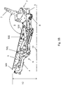
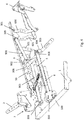
- Figure 1a shows the upright base position of the seating and lounging furniture. It comprises essentially a frame 1, a backrest 2, a seat element 3, and a footrest 4. Some of the other parts of the mechanism may possibly not be visible in Figure 1a ; therefore, in this regard reference is made to the two other Figures 1b and 1c , which respectively show a first intermediate position, and the reclining position with the footrest 4 extended.
- the seat element 3 is connected to the frame 1 by means of a seat element adjustment mechanism 5 for a displacement and tilting movement of the seat element 3 relative to the frame 1.
- the footrest 4 is connected to a front end 300 of the seat element 3 by means of a footrest adjustment mechanism 6 for extending and retracting the footrest 4.
- the backrest 2 is coupled to a rear end of the seat element 3 and to the frame 1 via a backrest adjustment mechanism 7.
- a first end 800 of the actuator 8 is coupled to the frame 1, and a second end 801 is coupled via a crossmember 803 to the seat element 3.
- the linear actuator For moving the sitting and reclining furniture from the upright base position according to Figure 1a ( Figure 3a ) into the first intermediate position according to Figure 1b ( Figure 3b ), the linear actuator carries out a first partial lift, whereby a displacement and pivoting movement of the seat element 3 relative to the frame 1 takes place without the footrest being extended.
- the seat element 3 is hereby lifted essentially at its front end 300, so that a first clear distance h1 between the front end 300 of the seat 3 and a floor 10, from the upright base position according to Figure 1a to the first intermediate position according to Figure 1b , changes into a greater second clear distance h2.
- the front end 300 of the seat element 3 is moved slightly forward relative to the frame 1.
- a second partial lift follows which brings about a change in position from the first intermediate position according to Figure 1b into the reclining position according to Figure 1c .
- the footrest 4 is extended relative to the seat element 3.
- the footrest 4 requires a clear height of at least h2 relative to the floor 10.
- the lower clear height h1 according to Figure 1a would not be sufficient for this purpose. Therefore, the mechanism is also designed so that the footrest 4 is not extended until during the second partial lift, in which the necessary clear height is present.
- the front end 300 is moved further forward by the length L, while at the same time, the angle between the backrest 2 and the seat element 3 further increases. This results in the reclining position according to Figure 1c .
- the angle ⁇ between the seat element 3 and the backrest 2 in the first intermediate position according to Figure 1b essentially corresponds to the angle ⁇ in the upright base position according to Figure 1[a] , or is slightly larger.
- the angle is approximately 100° +/- 5°, for example.
- an angle ⁇ which is approximately 20° +/- 5° larger than angle ⁇ results between the seat element 3 and the backrest 2.
- the clear height h1 in the upright base position is 270 mm +/- 10 mm, for example.
- the clear height h1 increases to approximately 305 mm +/- 10 mm, and in the reclining position according to Figure 1c may assume a height h3 of 347 mm +/- 10 mm, for example.
- the linear actuator 8 at its first end 8 [sic; 800] is articulatedly coupled to a transversely extending base support 100 of the frame 1.
- the linear actuator 8 is articulatedly coupled to a crossmember 803 via a short lever arm 804 that is nonrotatably connected to the crossmember 803.
- the coupling of the actuator is advantageously provided approximately in the middle of the crossmember 803.
- the crossmember extends to both sides of the seat element 3, and is pivotably connected thereto via one first articulation point 301 each.
- connecting plates 806 are nonrotatably fastened to the crossmember 803 at the two ends of the crossmember 803.
- the coupling to the first articulation point 301 is provided at one end of the connecting plate 806, while the footrest adjustment mechanism 6, made up of multiple parts, is articulatedly coupled at the other end.
- the footrest adjustment mechanism 6 is designed in the manner of a scissor mechanism, which with a first scissor arm 600 at a first articulation point 603 is articulatedly connected to the connecting plate 806 of the crossmember 803.
- a second scissor arm 601 of the footrest adjustment mechanism 6 is coupled to a first articulation point 900 of a linkage mechanism 9.
- This linkage mechanism 9 is made up of a first linkage part 901, a second linkage part 902, and a third linkage part 903, which are articulatedly coupled to one another.
- the first linkage part 901 at the first articulation point 900 is connected to the second scissor arm 601. At the other end, the first linkage part 901 is articulatedly connected to the second linkage part 902, in a middle area thereof.
- the second linkage part 902 at a second articulation point 904 is also coupled to the seat frame 3, and at the other end, at a third articulation point 905 is connected to the third linkage part 903, which at a fourth articulation point 906 in turn is coupled to the backrest adjustment mechanism 7.
- the seat element 3 has a fastening plate 302 which is fixedly connected thereto and which has a second articulation point 303 for coupling the backrest 2, and a third articulation point 304 for articulating the backrest adjustment mechanism 7.
- the backrest adjustment mechanism 7 has a connecting element 700 which is articulatedly coupled to the third articulation point 304, and which on the one hand is connected to the backrest 2 via a first articulated arm 701, and on the one hand is connected to the third linkage part 903 of the linkage mechanism in the area of the fourth articulation point 906.
- the seat element adjustment mechanism 5 has a plurality of lever arms and connecting plates.
- the seat element adjustment mechanism 5 in particular has a first lever arm 500 and a second lever arm 501 that are articulatedly connected to the seat element 3.
- a stop element 503 ( Figures 1a through 1c ) is provided on the seat element 3, and at the end of the first partial lift comes into contact with the first lever arm 500 and blocks further pivoting movement thereof ( Figure 1b ). The contact of the lever arm with the stop element 503 thus represents reaching the first intermediate position according to Figure 1b at the end of the first partial lift.
- the second end 801 of the linear actuator 8 is articulatedly coupled to the support 803 about a first articulation axis 805.
- the second scissor arm 601 of the footrest adjustment mechanism 6 on the seat element 3a is coupled to the first articulation point 301, which forms a second articulation axis 307 that is oriented in parallel to the first articulation axis 805.
- Both axes are also oriented perpendicularly with respect to the lift direction of the linear actuator 8, whereby the distance between the first articulation axis 805 and the second articulation axis 307, perpendicular to the lift direction of the linear actuator 8, in the upright base position according to Figures 1a , 2a , and 3a is smaller than at the end of the first partial lift of the linear actuator.
- the distance, if present at all, is only a few millimeters. However, this distance represents the lever arm via which the force of the linear actuator is transmitted to the footrest adjustment mechanism 6 in order to extend the footrest 4. The smaller this lever arm, the greater the force that is necessary for extending the footrest.
- the force required for the displacement and pivoting movement of the seat element 3 relative to the frame 3 [sic; 1] is much less during the first partial lift, so that, as desired, only the displacement and tilting movement of the seat element 3 takes place during the first partial lift, while the footrest 4 undergoes little or no movement.
- At least one spring element 504 may be provided which is situated between the frame 1 and the seat element 3, or, as in the illustrated exemplary embodiment, between the seat element 3 and the seat element adjustment mechanism 5. In the upright base position according to Figure 1a , the spring is pretensioned in such a way that the movement of the seat element 3 into the first intermediate position according to Figure 1b is assisted.
- the mechanism described above by use of a single linear actuator 8, thus allows a movement of the seat element 3 and backrest 2 independently of the footrest 4 during the first partial lift, and allows a synchronous movement of the backrest 2, seat element 3, and footrest 4 during the second partial lift.
- the crossmember 803 is articulatedly connected to the seat element 3 via the first articulation point 301.
- the crossmember 803 is also articulatedly coupled to the first scissor arm 600 of the footrest adjustment mechanism via the short lever arm 804. This coupling to the footrest adjustment mechanism 6 results in good stability and rigidity of the footrest 4 during use, in particular in the reclining position according to Figure 1c .
- first scissor arm 600 of the footrest adjustment mechanism 6 at the first articulation point 301, and the second scissor arm 601 at a fourth articulation point 305, are articulatedly connected to the seat element 3.
- the movement of the footrest 4 then takes place solely via the first linkage part 901 of the linkage mechanism 9 connected to the second scissor arm 601.
- the actuator 8 via its crossmember 803 is articulatedly coupled to a fifth articulation point 306, and via this coupling point transfers the lift of the linear actuator 8 to the seat element 3.
Landscapes
- Health & Medical Sciences (AREA)
- Dentistry (AREA)
- General Health & Medical Sciences (AREA)
- Chairs For Special Purposes, Such As Reclining Chairs (AREA)
Description
- The invention relates to seating and lounging furniture having a frame, a backrest, a seat element, and a footrest.
- Seating and lounging furniture is characterized in that it may be brought from an upright base position into a reclining position. Designs of this type are known in the market, in which the adjustment from the upright base position into the reclining position takes place solely by a shift in weight. In many designs, a footrest may also be extended.
- In
DE 20 2007 006 440 U1 it is proposed that the displacement of the seat part and the simultaneous inclination of the back part takes place by a shift in weight of a user of the reclining chair. In addition, a footrest may be independently retracted and extended by means of an electric motor. It is thus possible for the footrest to be extended and retracted, regardless of the position of the backrest. - Furthermore, a reclining chair is known from
EP 3 143 902 A1 -
US 5 556 158 A discloses a chair that can be moved from a fully upright position to a comfortable "TV"-position with an extended footrest. The mechanism can be actuated by an occupant with or without an actuator resulting in an unfolding of the footrest and simultaneous inclination of a backrest. - The object of the invention is to develop seating and lounging furniture that implements a motor-driven individual adjustment of the backrest and the footrest in a more cost-effective manner.
- This object is achieved according to the invention by the features of
Claim 1. - The seating and lounging furniture according to the invention provides a frame, a backrest, a seat element, and a footrest, wherein
- the seat element is connected to the frame by means of a seat element adjustment mechanism for a displacement and tilting movement of the seat element relative to the frame,
- the footrest is connected to a front end of the seat element by means of a footrest adjustment mechanism for extending and retracting the footrest,
- the backrest is connected to a rear end of the seat element and to the frame via a backrest adjustment mechanism,
- only one linear actuator is provided for adjusting the seat element, the footrest, and the backrest between an upright base position and a reclining position of the seating and lounging furniture, wherein
- a first end of the actuator is coupled to the frame, and a second end is coupled to the seat element,
- the linear actuator when actuated generates a linear lift, made up of a first partial lift and a second partial lift, the first partial lift bringing about the displacement and pivoting movement of the seat element relative to the frame without an extension or retraction of the footrest, and the second partial lift bringing about a synchronous inclination of the backrest relative to the seat element and an extension or retraction of the footrest relative to the seat element.
- The seating and lounging furniture according to the invention allows a displacement and pivoting movement of the seat element relative to the frame without the footrest being extended in the process. However, with the same linear actuator, the extension and retraction of the footrest is then also possible with a further partial lift.
- Thus, compared to
EP 3 143 902 A1 - The seating and lounging furniture according to the invention further comprises a linkage mechanism which connects the backrest, the seat element, and the footrest to one another. This linkage mechanism includes a first linkage part, a second linkage part and a third linkage part that are coupled together. The first linkage part hereby couples the footrest adjustment mechanism to the second linkage part, while the second linkage part is coupled to the seat element, and the third linkage part connects the second linkage part to the backrest adjustment mechanism. This linkage mechanism thus represents a connection between the three movable parts (seat element, backrest, and footrest), and forms one conceivable exemplary embodiment for moving all three parts via a single actuator, however, with the footrest not being actuated until during the second partial lift.
- Further embodiments of the invention are the subject matter of the subclaims.
- According to a first embodiment of the invention, the seat element and the backrest in the base position enclose a first angle, and at the end of the first partial lift enclose a second angle, the first angle and the second angle differing from one another by less than 10°, preferably by less than 5°, and very preferably by less than 3°. It is also provided that this angle between the seat element and the backrest during the second partial lift increases by an angle of at least 10°, preferably by at least 15°, and very preferably by at least 20°. This has the effect that the actual reclining position does not result until during the second partial lift, in which the footrest is also extended. In contrast, only a slightly tilted-back position of the seat element and the backrest result after the first partial lift.
- In addition, a stop element may be provided for assisting in this motion sequence. This stop element comes into contact with the seat element adjustment mechanism at the end of the first partial lift of the linear actuator.
- Furthermore, at least one first spring element may be provided between the frame and the seat element, or between the frame and the seat element adjustment mechanism, for assisting in the displacement and pivoting movement of the seat element.
- According to another embodiment of the invention, the force to be applied for actuating the seat element adjustment mechanism, starting from the upright base position into the first intermediate position at the end of the first partial lift, is less than the force to be applied for actuating the footrest adjustment mechanism. This ensures that the footrest is not extended until the second partial lift of the linear actuator.
- In one particular exemplary embodiment of the invention, the linear actuator is coupled to the seat element via a crossmember. In particular, the second end of the linear actuator may be articulatedly coupled to the crossmember about a first articulation axis, while the footrest adjustment mechanism is coupled to the seat element about a parallel second articulation axis, whereby the distance, perpendicular to the lift direction of the linear actuator, between the first and the second articulation axis in the upright base position is smaller than at the end of the first partial lift of the linear actuator. The smaller the distance at the beginning of the first partial lift, the smaller the effective lever arm and the greater the force that is necessary for extending the footrest. The distance between the two axes is therefore dimensioned small enough that the footrest does not move at all or hardly moves during the first partial lift of the linear actuator. In the tests underlying the invention, it has been found to be advantageous when the distance, perpendicular to the lift direction of the linear actuator, between the first and the second articulation axis is selected to be less than 3 mm in the upright base position of the sitting and reclining furniture.
- In another embodiment of the invention, it is provided that the seat element adjustment mechanism moves the seat element from the upright base position into a first intermediate position at the end of the first partial lift, wherein in the upright base position a first clear distance is formed between the front end of the seat element and a floor, and in the first intermediate position a second clear distance is formed between the front end of the seat element and the floor, the first clear distance being less than the second clear distance. Due to this lifting of the front end of the seat element, the clear distance from the floor, necessary for extending and retracting the footrest, may be selected to be greater than the first clear distance that is present in the upright base position, provided that the greater second clear distance in the intermediate position is sufficient to extend the footrest. The frame of the seating and lounging furniture may thus have a lower design, and the space that is gained may be utilized, for example, for thicker padding of the seat element. However, extending the footrest is still possible, since the necessary space is initially provided by lifting the front area of the seat element. However, this in turn requires that the footrest is not moved or is hardly moved during the first partial lift, in which the necessary distance is not yet great enough. Therefore, the footrest is not extended until during the second partial lift, when the necessary clear distance is present.
- Further embodiments of the invention are explained in greater detail below with reference to the description of several exemplary embodiments, and the drawings, which show the following:
- Figure 1a
- shows a side view of the seating and lounging furniture in the upright base position,
- Figure 1b
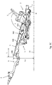
- shows a side view of the seating and lounging furniture in the intermediate position,
- Figure 1c
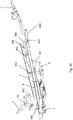
- shows a side view of the seating and lounging furniture in the reclining position with the footrest extended,
- Figure 2a
- shows an enlarged second side view of the seating and lounging furniture in the upright base position according to
Figure 1a , - Figure 2b
- shows an enlarged second side view of the seating and lounging furniture in the intermediate position according to
Figure 1b , - Figure 2c
- shows an enlarged second side view of the seating and lounging furniture in the reclining position according to
Figure 1c , - Figure 3a
- shows a three-dimensional view in the position according to
Figure 1 a, - Figure 3b
- shows a three-dimensional view in the position according to
Figure 1b , - Figure 3c
- shows a three-dimensional view in the position according to
Figure 1c , and - Figure 4
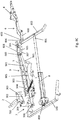
- shows a three-dimensional view of another exemplary embodiment in a position during the second partial lift.
- The illustrations in the drawings show essentially only the mechanism of the seating and lounging furniture. All parts not of interest here, such as the padding in particular, have been omitted to allow a better illustration of the essential elements.
Figure 1a shows the upright base position of the seating and lounging furniture. It comprises essentially aframe 1, abackrest 2, aseat element 3, and afootrest 4. Some of the other parts of the mechanism may possibly not be visible inFigure 1a ; therefore, in this regard reference is made to the two otherFigures 1b and1c , which respectively show a first intermediate position, and the reclining position with thefootrest 4 extended. - The
seat element 3 is connected to theframe 1 by means of a seatelement adjustment mechanism 5 for a displacement and tilting movement of theseat element 3 relative to theframe 1. Thefootrest 4 is connected to afront end 300 of theseat element 3 by means of afootrest adjustment mechanism 6 for extending and retracting thefootrest 4. In contrast, thebackrest 2 is coupled to a rear end of theseat element 3 and to theframe 1 via abackrest adjustment mechanism 7. For moving the seating and lounging furniture from the upright base position according toFigure 1a , via the first intermediate position according toFigure 1b , into the reclining position according toFigure 1c , only onelinear actuator 8, which moves theseat element 3 as well as thefootrest 4 and thebackrest 2, is provided. As is apparent in particular fromFigures 3a through 3c , afirst end 800 of theactuator 8 is coupled to theframe 1, and asecond end 801 is coupled via acrossmember 803 to theseat element 3. For moving the sitting and reclining furniture from the upright base position according toFigure 1a (Figure 3a ) into the first intermediate position according toFigure 1b (Figure 3b ), the linear actuator carries out a first partial lift, whereby a displacement and pivoting movement of theseat element 3 relative to theframe 1 takes place without the footrest being extended. Theseat element 3 is hereby lifted essentially at itsfront end 300, so that a first clear distance h1 between thefront end 300 of theseat 3 and afloor 10, from the upright base position according toFigure 1a to the first intermediate position according toFigure 1b , changes into a greater second clear distance h2. At the same time, thefront end 300 of theseat element 3 is moved slightly forward relative to theframe 1. - If the
linear actuator 8 is further actuated in the same direction, a second partial lift follows which brings about a change in position from the first intermediate position according toFigure 1b into the reclining position according toFigure 1c . This results in a synchronous inclination of thebackrest 2 relative to theseat element 3. In addition, thefootrest 4 is extended relative to theseat element 3. It is to be noted here that thefootrest 4 requires a clear height of at least h2 relative to thefloor 10. The lower clear height h1 according toFigure 1a would not be sufficient for this purpose. Therefore, the mechanism is also designed so that thefootrest 4 is not extended until during the second partial lift, in which the necessary clear height is present. During the second partial lift, thefront end 300 is moved further forward by the length L, while at the same time, the angle between thebackrest 2 and theseat element 3 further increases. This results in the reclining position according toFigure 1c . - The angle β between the
seat element 3 and thebackrest 2 in the first intermediate position according toFigure 1b essentially corresponds to the angle α in the upright base position according toFigure 1[a] , or is slightly larger. The angle is approximately 100° +/- 5°, for example. In the reclining position according toFigure 1c , an angle γ which is approximately 20° +/- 5° larger than angle β results between theseat element 3 and thebackrest 2. - In one exemplary embodiment of the invention, the clear height h1 in the upright base position is 270 mm +/- 10 mm, for example. In the intermediate position according to
Figure 1b , the clear height h1 increases to approximately 305 mm +/- 10 mm, and in the reclining position according toFigure 1c may assume a height h3 of 347 mm +/- 10 mm, for example. - Further embodiments of the mechanism are described in greater detail below with reference to
Figures 2a through 3c . Thelinear actuator 8 at its first end 8 [sic; 800] is articulatedly coupled to a transversely extendingbase support 100 of theframe 1. At itssecond end 801 thelinear actuator 8 is articulatedly coupled to acrossmember 803 via ashort lever arm 804 that is nonrotatably connected to thecrossmember 803. The coupling of the actuator is advantageously provided approximately in the middle of thecrossmember 803. The crossmember extends to both sides of theseat element 3, and is pivotably connected thereto via onefirst articulation point 301 each. For this purpose, connectingplates 806 are nonrotatably fastened to thecrossmember 803 at the two ends of thecrossmember 803. The coupling to thefirst articulation point 301 is provided at one end of the connectingplate 806, while thefootrest adjustment mechanism 6, made up of multiple parts, is articulatedly coupled at the other end. Thefootrest adjustment mechanism 6 is designed in the manner of a scissor mechanism, which with afirst scissor arm 600 at afirst articulation point 603 is articulatedly connected to the connectingplate 806 of thecrossmember 803. Asecond scissor arm 601 of thefootrest adjustment mechanism 6 is coupled to afirst articulation point 900 of alinkage mechanism 9. Thislinkage mechanism 9 is made up of afirst linkage part 901, asecond linkage part 902, and athird linkage part 903, which are articulatedly coupled to one another. Thefirst linkage part 901 at thefirst articulation point 900 is connected to thesecond scissor arm 601. At the other end, thefirst linkage part 901 is articulatedly connected to thesecond linkage part 902, in a middle area thereof. Thesecond linkage part 902 at asecond articulation point 904 is also coupled to theseat frame 3, and at the other end, at athird articulation point 905 is connected to thethird linkage part 903, which at afourth articulation point 906 in turn is coupled to thebackrest adjustment mechanism 7. - The
seat element 3 has afastening plate 302 which is fixedly connected thereto and which has asecond articulation point 303 for coupling thebackrest 2, and athird articulation point 304 for articulating thebackrest adjustment mechanism 7. - The
backrest adjustment mechanism 7 has a connectingelement 700 which is articulatedly coupled to thethird articulation point 304, and which on the one hand is connected to thebackrest 2 via a first articulatedarm 701, and on the one hand is connected to thethird linkage part 903 of the linkage mechanism in the area of thefourth articulation point 906. - The seat
element adjustment mechanism 5 has a plurality of lever arms and connecting plates. For the displacement and tilting movement of theseat element 3, the seatelement adjustment mechanism 5 in particular has afirst lever arm 500 and asecond lever arm 501 that are articulatedly connected to theseat element 3. In addition, a stop element 503 (Figures 1a through 1c ) is provided on theseat element 3, and at the end of the first partial lift comes into contact with thefirst lever arm 500 and blocks further pivoting movement thereof (Figure 1b ). The contact of the lever arm with thestop element 503 thus represents reaching the first intermediate position according toFigure 1b at the end of the first partial lift. During this first partial lift, the angle α formed by thebackrest 2 and theseat element 3 in the upright base position according toFigure 1a undergoes little or no change. The angle β between thebackrest 2 and theseat element 3 is therefore identical to or only slightly larger than the angle α in the intermediate position according toFigure 1b . - At the
short lever arm 804, thesecond end 801 of thelinear actuator 8 is articulatedly coupled to thesupport 803 about afirst articulation axis 805. In addition, thesecond scissor arm 601 of thefootrest adjustment mechanism 6 on the seat element 3a is coupled to thefirst articulation point 301, which forms asecond articulation axis 307 that is oriented in parallel to thefirst articulation axis 805. Both axes are also oriented perpendicularly with respect to the lift direction of thelinear actuator 8, whereby the distance between thefirst articulation axis 805 and thesecond articulation axis 307, perpendicular to the lift direction of thelinear actuator 8, in the upright base position according toFigures 1a ,2a , and3a is smaller than at the end of the first partial lift of the linear actuator. The distance, if present at all, is only a few millimeters. However, this distance represents the lever arm via which the force of the linear actuator is transmitted to thefootrest adjustment mechanism 6 in order to extend thefootrest 4. The smaller this lever arm, the greater the force that is necessary for extending the footrest. In contrast, the force required for the displacement and pivoting movement of theseat element 3 relative to the frame 3 [sic; 1] is much less during the first partial lift, so that, as desired, only the displacement and tilting movement of theseat element 3 takes place during the first partial lift, while thefootrest 4 undergoes little or no movement. - During the first partial lift, the movement of the
seat element 3 causes an increase in the distance between thefirst articulation axis 805 and thesecond articulation axis 307, so that the lever arm, which acts to transmit force, is lengthened until thefootrest 4 is now extended during the second partial lift. In addition, to assist in the displacement and pivoting movement of theseat element 4, at least onespring element 504 may be provided which is situated between theframe 1 and theseat element 3, or, as in the illustrated exemplary embodiment, between theseat element 3 and the seatelement adjustment mechanism 5. In the upright base position according toFigure 1a , the spring is pretensioned in such a way that the movement of theseat element 3 into the first intermediate position according toFigure 1b is assisted. - During the second partial lift of the
linear actuator 8, on the one hand thefootrest 4 is extended, and on the other hand this results in synchronous inclination of thebackrest 2 relative to theseat element 3, theseat element 3 also being further inclined by thefront end 300 being further lifted. In the reclining position according toFigure 1c , the angle γ between thebackrest 2 and theseat element 3 has increased by approximately 20°. For an oppositely directed activation of thelinear actuator 8, starting from the reclining position according toFigure 1c , a corresponding opposite movement of thebackrest 2,seat element 3, andfootrest 4 takes place. In particular, the first intermediate position according toFigure 1b is also reached. - The mechanism described above, by use of a single
linear actuator 8, thus allows a movement of theseat element 3 andbackrest 2 independently of thefootrest 4 during the first partial lift, and allows a synchronous movement of thebackrest 2,seat element 3, andfootrest 4 during the second partial lift. - In the exemplary embodiment described above, the
crossmember 803 is articulatedly connected to theseat element 3 via thefirst articulation point 301. However, thecrossmember 803 is also articulatedly coupled to thefirst scissor arm 600 of the footrest adjustment mechanism via theshort lever arm 804. This coupling to thefootrest adjustment mechanism 6 results in good stability and rigidity of thefootrest 4 during use, in particular in the reclining position according toFigure 1c . - Within the scope of the invention, however, it would also be conceivable for the
actuator 8 to be coupled only to theseat element 3, and for the movement of thefootrest 4 to be transferred only via thelinkage mechanism 9. - Such an alternative exemplary embodiment is illustrated in
Figure 4 . The same reference numerals have been used for identical parts for better understanding. - It is apparent that the
first scissor arm 600 of thefootrest adjustment mechanism 6 at thefirst articulation point 301, and thesecond scissor arm 601 at afourth articulation point 305, are articulatedly connected to theseat element 3. The movement of thefootrest 4 then takes place solely via thefirst linkage part 901 of thelinkage mechanism 9 connected to thesecond scissor arm 601. Theactuator 8 via itscrossmember 803 is articulatedly coupled to afifth articulation point 306, and via this coupling point transfers the lift of thelinear actuator 8 to theseat element 3.
Claims (12)
- Seating and lounging furniture having a frame (1), a backrest (2), a seat element (3), and a footrest, wherein- the seat element (3) is connected to the frame (1) by means of a seat element adjustment mechanism (5) for a displacement and tilting movement of the seat element (3) relative to the frame (1),- the footrest (4) is connected to a front end (300) of the seat element (3) by means of a footrest adjustment mechanism (6) for extending and retracting the footrest (4),- the backrest (2) is connected to a rear end of the seat element (3) and to the frame (1) via a backrest adjustment mechanism (7),- only one linear actuator (8) is provided for adjusting the seat element (3), the footrest (4), and the backrest (2) between an upright base position and a reclining position of the seating and lounging furniture, wherein the linear actuator (8) when actuated generates a linear lift, made up of a first partial lift and a second partial lift,
characterized in that a linkage mechanism (9) is provided which connects the backrest (2), the seat element (3), and the footrest (4) to one another, wherein the linkage mechanism includes a first linkage part (901), a second linkage part (902), and a third linkage part (903) that are coupled together and wherein- the first linkage part (901) couples the footrest adjustment mechanism (6) to the second linkage part (902),- the second linkage part (902) is coupled to the seat element (3), and- the third linkage part (903) couples the second linkage part (902) to the backrest adjustment mechanism (7),- a first end (800) of the actuator (8) is coupled to the frame (1), and a second end (801) is coupled to the seat element (3),- , the first partial lift bringing about the displacement and pivoting movement of the seat element (3) relative to the frame (1) without an extension or retraction of the footrest (4), and the second partial lift bringing about a synchronous inclination of the backrest (2) relative to the seat element (3) and an extension or retraction of the footrest (4) relative to the seat element (3). - The seating and lounging furniture according to Claim 1, wherein the seat element (3) and the backrest (2) in the base position enclose a first angle (α), and at the end of the first partial lift enclose a second angle (β), the first angle (α) and the second angle (β) differing from one another by less than 10°.
- The seating and lounging furniture according to Claim 1, wherein the angle between the seat element (3) and the backrest (2) during the second partial lift increases by an angle of at least 10°.
- The seating and lounging furniture according to Claim 1, wherein a stop element (503) is provided which comes into contact with the seat element adjustment mechanism (5) at the end of the first partial lift of the linear actuator (8).
- The seating and lounging furniture according to Claim 1, wherein at least one spring element (504) is provided between the frame (1) and the seat element (3), or between the frame (1) and the seat element adjustment mechanism (5), for assisting in the displacement and pivoting movement of the seat element (3).
- The seating and lounging furniture according to Claim 1, wherein the force to be applied for actuating the seat element adjustment mechanism (5), starting from the upright base position, is less than the force to be applied for actuating the footrest adjustment mechanism (6).
- The seating and lounging furniture according to Claim 1, wherein the linear actuator (8) is coupled to the seat element (3) via a crossmember (803).
- The seating and lounging furniture according to Claim 7, wherein the second end (801) of the linear actuator (8) is articulatedly coupled to the crossmember (803) about a first articulation axis (805), and the footrest adjustment mechanism (6) is coupled to the seat element (3) about a parallel second articulation axis (604), whereby the distance, perpendicular to the lift direction of the linear actuator (8), between the first and the second articulation axis (805, 604), in the upright base position is smaller than at the end of the first partial lift of the linear actuator (8).
- The seating and lounging furniture according to Claim 8, wherein the distance, perpendicular to the lift direction of the linear actuator (8), between the first and the second articulation axis (805, 604) is less than 3 mm in the upright base position of the sitting and reclining furniture.
- The seating and lounging furniture according to Claim 7, wherein the crossmember (803) is also connected to the footrest adjustment mechanism (6).
- The seating and lounging furniture according to Claim 1, wherein the seat element adjustment mechanism (5) moves the seat element (3) from the upright base position (P0) into a first intermediate position at the end of the first partial lift, wherein in the upright base position (P0) a first clear distance (h1) is formed between the front end (300) of the seat element (3) and a floor, and in the first intermediate position a second clear distance (h2) is formed between the front end (300) of the seat element (3) and a floor (10), the first clear distance (h1) being less than the second clear distance (h2).
- The seating and lounging furniture according to Claim 11, wherein the clear distance from the floor (10), necessary for extending and retracting the footrest (4), is greater than the first clear distance (h1) that is present in the upright base position, and less than the second clear distance (h2) that is present in the first intermediate position.
Priority Applications (1)
| Application Number | Priority Date | Filing Date | Title |
|---|---|---|---|
| PL18172854T PL3412176T3 (en) | 2017-06-07 | 2018-05-17 | Seating and lounging furniture |
Applications Claiming Priority (1)
| Application Number | Priority Date | Filing Date | Title |
|---|---|---|---|
| DE202017103410.0U DE202017103410U1 (en) | 2017-06-07 | 2017-06-07 | Seating and reclining furniture |
Publications (2)
| Publication Number | Publication Date |
|---|---|
| EP3412176A1 EP3412176A1 (en) | 2018-12-12 |
| EP3412176B1 true EP3412176B1 (en) | 2020-01-01 |
Family
ID=59382509
Family Applications (1)
| Application Number | Title | Priority Date | Filing Date |
|---|---|---|---|
| EP18172854.4A Active EP3412176B1 (en) | 2017-06-07 | 2018-05-17 | Seating and lounging furniture |
Country Status (6)
| Country | Link |
|---|---|
| US (1) | US10441081B2 (en) |
| EP (1) | EP3412176B1 (en) |
| CN (1) | CN108991793B (en) |
| DE (1) | DE202017103410U1 (en) |
| ES (1) | ES2767126T3 (en) |
| PL (1) | PL3412176T3 (en) |
Cited By (1)
| Publication number | Priority date | Publication date | Assignee | Title |
|---|---|---|---|---|
| US12458145B2 (en) | 2021-08-31 | 2025-11-04 | Ferdinand Lusch Gmbh | Swivel fitting of seating furniture for adjusting a foot part and seating furniture with adjustable foot part |
Families Citing this family (18)
| Publication number | Priority date | Publication date | Assignee | Title |
|---|---|---|---|---|
| DE202018104073U1 (en) * | 2018-07-16 | 2018-07-24 | Ciar S.P.A. | Sitting and / or lying furniture |
| DE202020106464U1 (en) * | 2020-11-11 | 2020-12-02 | Ciar S.P.A. | Seating furniture with stand-up aid |
| DK4266949T3 (en) * | 2020-12-28 | 2025-04-28 | M Schuster Patentverwertungs Gmbh | Seating furniture with telescopic leg support element |
| WO2022144055A1 (en) * | 2020-12-28 | 2022-07-07 | Michael Schuster | Seating furniture item with telescopic leg support element and separate seat inclination adjustment means |
| CN116829032A (en) * | 2020-12-28 | 2023-09-29 | M·舒斯特专利实施有限责任公司 | Seating furniture with retractable legrest elements and independent seat tilt adjustment |
| CN116829031A (en) * | 2020-12-28 | 2023-09-29 | M·舒斯特专利实施有限责任公司 | Seating furniture with retractable leg rest elements |
| CN113212278B (en) * | 2021-06-16 | 2025-03-25 | 湖南智行达科技有限公司 | DC locomotive lifting pedal |
| CN216020114U (en) * | 2021-08-26 | 2022-03-15 | 海宁和力机械科技有限公司 | Seat moving device and seat assembly |
| US12232617B2 (en) * | 2021-11-30 | 2025-02-25 | Dewertokin Technology Group Co., Ltd. | Seat frame |
| USD1059103S1 (en) | 2022-09-15 | 2025-01-28 | Smith System Manufacturing Company | Chair |
| US12022949B2 (en) * | 2022-10-13 | 2024-07-02 | Hidden Lake 822, Llc | Drive motor-linear actuator system for powered lift or powered reclining chairs |
| CN121127160A (en) * | 2023-05-06 | 2025-12-12 | L & P 产权管理公司 | Wooden floor-standing recliner mechanism with prominent backrest pivot point |
| CN220001288U (en) * | 2023-05-08 | 2023-11-14 | 海宁和力机械科技有限公司 | Seat framework and seat capable of switching sitting and lying postures |
| CN219813618U (en) * | 2023-05-24 | 2023-10-13 | 海宁和力机械科技有限公司 | Seat frames and leisure seats |
| CN116671743B (en) * | 2023-07-22 | 2026-02-17 | 顾家家居股份有限公司 | A linkage mechanism and a seating system |
| CN220571844U (en) * | 2023-08-02 | 2024-03-12 | 锐迈科技股份有限公司 | Mechanical extension devices for movable seating units and seating units |
| KR20250089663A (en) * | 2023-12-12 | 2025-06-19 | 현대자동차주식회사 | Rotation mechanism and seat including the same |
| MX2024004286A (en) * | 2024-04-05 | 2024-08-08 | Ind Nortecaucanas S A S | Reclining chair with reclining mechanism and reclining mechanism assembly for stepping rooms. |
Family Cites Families (24)
| Publication number | Priority date | Publication date | Assignee | Title |
|---|---|---|---|---|
| US3300244A (en) * | 1966-01-06 | 1967-01-24 | Claude A Hughes | Reclining chair |
| US5147108A (en) * | 1990-10-18 | 1992-09-15 | La-Z-Boy Chair Company | Reclining sofa |
| US5129701A (en) * | 1990-10-26 | 1992-07-14 | Dbju, Inc. | Double-shift carriage mechanism for full recline incliner chair |
| US5556158A (en) * | 1994-07-19 | 1996-09-17 | L&P Property Management Co. | Mechanism for reclining furniture |
| BR9502131A (en) * | 1995-05-23 | 1997-08-26 | Lafer S A Ind E Comercio | Armchair |
| US5775775A (en) * | 1995-09-14 | 1998-07-07 | Ultra-Mek, Inc. | Reclining seating unit and method for constructing same |
| US5971475A (en) * | 1996-12-05 | 1999-10-26 | Omega Motion Llc | Three-way incliner |
| US6135559A (en) * | 1997-07-31 | 2000-10-24 | Hickory Springs Manufacturing Co. | Seat back reclining mechanism adaptable to chairs with stationary or movable seats |
| DE20106560U1 (en) * | 2001-04-14 | 2002-08-29 | Dewert Antriebs- und Systemtechnik GmbH & Co KG, 32278 Kirchlengern | Seat-recliner armchair adjustable by motor |
| GB0325358D0 (en) * | 2003-10-30 | 2003-12-03 | Peter Cook Internat Plc | Powered furniture |
| WO2008129565A1 (en) | 2007-04-18 | 2008-10-30 | Stema S.R.L. | Mechanism for reclining armchairs or sofas |
| DE202007006440U1 (en) | 2007-05-05 | 2007-07-12 | Ferdinand Lusch Gmbh & Co. Kg | Recliner chair, comprises footrest moved independently of seat and backrest by electric drive |
| US8419122B2 (en) * | 2010-01-25 | 2013-04-16 | L & P Property Management Company | Zero-wall clearance linkage mechanism for a high-leg seating unit |
| US8944498B2 (en) * | 2012-01-05 | 2015-02-03 | L & Property Management Company | Linkage mechanism for a dual-motor lifting recliner |
| CN202892335U (en) * | 2012-11-12 | 2013-04-24 | 常州市锐新医疗器械有限公司 | Horizontal multi-link extension mechanism |
| US9398810B2 (en) * | 2013-08-21 | 2016-07-26 | L & P Property Management Company | Reclining and ottoman-extending chair mechanism |
| US9635943B2 (en) * | 2014-03-28 | 2017-05-02 | L&P Property Management Company | Wall-proximity reclining mechanism with consistent-height seat |
| JP2017511272A (en) * | 2014-03-28 | 2017-04-20 | ビーイー・エアロスペース・インコーポレーテッドB/E Aerospace, Inc. | Aircraft seat with split seat back to achieve chaise longue |
| US10021980B2 (en) | 2014-07-22 | 2018-07-17 | L&P Property Management Company | Zero-wall clearance linkage mechanism with power seat drive |
| US9332844B2 (en) * | 2014-10-08 | 2016-05-10 | Aminach Bedding & Furniture Manufacturing Ltd. | Electrically controlled recliner with independent rocker-limiting mechanism |
| US9480336B1 (en) | 2015-04-15 | 2016-11-01 | American Leather Operations, Llc | Motion furniture with deployable headrest |
| EP3143902B2 (en) * | 2015-09-15 | 2023-04-26 | Ciar S.P.A. | Wall hugger recliner |
| CN105996517A (en) * | 2016-06-25 | 2016-10-12 | 杭州广鑫进出口有限公司 | Flexing frame applied to seat unit and seat unit |
| DE202016104352U1 (en) * | 2016-08-08 | 2016-08-18 | Ciar S.P.A. | seat |
-
2017
- 2017-06-07 DE DE202017103410.0U patent/DE202017103410U1/en not_active Expired - Lifetime
-
2018
- 2018-05-17 EP EP18172854.4A patent/EP3412176B1/en active Active
- 2018-05-17 ES ES18172854T patent/ES2767126T3/en active Active
- 2018-05-17 PL PL18172854T patent/PL3412176T3/en unknown
- 2018-05-30 CN CN201810539557.0A patent/CN108991793B/en active Active
- 2018-06-05 US US16/000,217 patent/US10441081B2/en active Active
Non-Patent Citations (1)
| Title |
|---|
| None * |
Cited By (1)
| Publication number | Priority date | Publication date | Assignee | Title |
|---|---|---|---|---|
| US12458145B2 (en) | 2021-08-31 | 2025-11-04 | Ferdinand Lusch Gmbh | Swivel fitting of seating furniture for adjusting a foot part and seating furniture with adjustable foot part |
Also Published As
| Publication number | Publication date |
|---|---|
| CN108991793B (en) | 2022-11-08 |
| US20180352960A1 (en) | 2018-12-13 |
| CN108991793A (en) | 2018-12-14 |
| EP3412176A1 (en) | 2018-12-12 |
| ES2767126T3 (en) | 2020-06-16 |
| US10441081B2 (en) | 2019-10-15 |
| DE202017103410U1 (en) | 2017-07-05 |
| PL3412176T3 (en) | 2020-06-29 |
Similar Documents
| Publication | Publication Date | Title |
|---|---|---|
| US10441081B2 (en) | Seating and lounging furniture | |
| EP2010028B1 (en) | Seating furniture with lift mechanism | |
| EP3860403B1 (en) | Reclining seating unit with wall-proximity capability | |
| AU2011207793B2 (en) | Zero-wall clearance linkage mechanism for high-leg seating unit | |
| CA2740958C (en) | Lumbar support system for furniture member | |
| EP3616983B1 (en) | Adjustment device for a headrest | |
| WO2001060211B1 (en) | Adjustable chair | |
| MXPA97002609A (en) | Backup assembly for legs d | |
| CN113017329B (en) | Seating furniture and fitting for seating furniture | |
| CN112512378B (en) | Single Electric Bidirectional Actuator System for Linear, Smooth Movement of Furniture Structures | |
| MX2011004024A (en) | Adjustable headrest assembly for furniture member. | |
| CN114080175A (en) | Seating furniture with recliner function and outwardly pivotable foot parts | |
| EP1164899B1 (en) | Arrangement for beds and other reclining or seating furniture | |
| KR20140007487A (en) | Vehicle seat, in particular motor vehicle seat | |
| CN103732444A (en) | Vehicle seat, in particular motor vehicle seat | |
| US7100985B2 (en) | Seat in particular a vehicle seat preferably an aeroplane seat | |
| CN106794102A (en) | Electric wheelchair with armrest adjustment | |
| EP1161904A1 (en) | Chair with seat and backrest that oscillate in a synchronized way | |
| EP1361968B1 (en) | Foldable vehicle seat from a use position to a stowed position and related layout of a seat assembly | |
| CN215913918U (en) | Double-motor stretching device of sofa | |
| US20230337824A1 (en) | Piece of seating furniture having a telescoping leg-rest element | |
| US20050269844A1 (en) | Vehicle seat, especially aircraft passenger seat | |
| EP3417741B1 (en) | A unit for the change of backrest and footrest position of a leisure furniture | |
| CN120475923A (en) | Sitting furniture and furniture accessories for sitting furniture | |
| CN121263108A (en) | Seating furniture and furniture fittings therefor |
Legal Events
| Date | Code | Title | Description |
|---|---|---|---|
| PUAI | Public reference made under article 153(3) epc to a published international application that has entered the european phase |
Free format text: ORIGINAL CODE: 0009012 |
|
| STAA | Information on the status of an ep patent application or granted ep patent |
Free format text: STATUS: THE APPLICATION HAS BEEN PUBLISHED |
|
| AK | Designated contracting states |
Kind code of ref document: A1 Designated state(s): AL AT BE BG CH CY CZ DE DK EE ES FI FR GB GR HR HU IE IS IT LI LT LU LV MC MK MT NL NO PL PT RO RS SE SI SK SM TR |
|
| AX | Request for extension of the european patent |
Extension state: BA ME |
|
| STAA | Information on the status of an ep patent application or granted ep patent |
Free format text: STATUS: REQUEST FOR EXAMINATION WAS MADE |
|
| 17P | Request for examination filed |
Effective date: 20190109 |
|
| RBV | Designated contracting states (corrected) |
Designated state(s): AL AT BE BG CH CY CZ DE DK EE ES FI FR GB GR HR HU IE IS IT LI LT LU LV MC MK MT NL NO PL PT RO RS SE SI SK SM TR |
|
| GRAP | Despatch of communication of intention to grant a patent |
Free format text: ORIGINAL CODE: EPIDOSNIGR1 |
|
| STAA | Information on the status of an ep patent application or granted ep patent |
Free format text: STATUS: GRANT OF PATENT IS INTENDED |
|
| INTG | Intention to grant announced |
Effective date: 20190730 |
|
| GRAS | Grant fee paid |
Free format text: ORIGINAL CODE: EPIDOSNIGR3 |
|
| GRAA | (expected) grant |
Free format text: ORIGINAL CODE: 0009210 |
|
| STAA | Information on the status of an ep patent application or granted ep patent |
Free format text: STATUS: THE PATENT HAS BEEN GRANTED |
|
| AK | Designated contracting states |
Kind code of ref document: B1 Designated state(s): AL AT BE BG CH CY CZ DE DK EE ES FI FR GB GR HR HU IE IS IT LI LT LU LV MC MK MT NL NO PL PT RO RS SE SI SK SM TR |
|
| REG | Reference to a national code |
Ref country code: GB Ref legal event code: FG4D |
|
| REG | Reference to a national code |
Ref country code: CH Ref legal event code: EP Ref country code: AT Ref legal event code: REF Ref document number: 1218707 Country of ref document: AT Kind code of ref document: T Effective date: 20200115 |
|
| REG | Reference to a national code |
Ref country code: IE Ref legal event code: FG4D |
|
| REG | Reference to a national code |
Ref country code: DE Ref legal event code: R096 Ref document number: 602018001856 Country of ref document: DE |
|
| REG | Reference to a national code |
Ref country code: NL Ref legal event code: FP |
|
| REG | Reference to a national code |
Ref country code: ES Ref legal event code: FG2A Ref document number: 2767126 Country of ref document: ES Kind code of ref document: T3 Effective date: 20200616 |
|
| REG | Reference to a national code |
Ref country code: LT Ref legal event code: MG4D |
|
| PG25 | Lapsed in a contracting state [announced via postgrant information from national office to epo] |
Ref country code: CZ Free format text: LAPSE BECAUSE OF FAILURE TO SUBMIT A TRANSLATION OF THE DESCRIPTION OR TO PAY THE FEE WITHIN THE PRESCRIBED TIME-LIMIT Effective date: 20200101 Ref country code: PT Free format text: LAPSE BECAUSE OF FAILURE TO SUBMIT A TRANSLATION OF THE DESCRIPTION OR TO PAY THE FEE WITHIN THE PRESCRIBED TIME-LIMIT Effective date: 20200527 Ref country code: LT Free format text: LAPSE BECAUSE OF FAILURE TO SUBMIT A TRANSLATION OF THE DESCRIPTION OR TO PAY THE FEE WITHIN THE PRESCRIBED TIME-LIMIT Effective date: 20200101 Ref country code: FI Free format text: LAPSE BECAUSE OF FAILURE TO SUBMIT A TRANSLATION OF THE DESCRIPTION OR TO PAY THE FEE WITHIN THE PRESCRIBED TIME-LIMIT Effective date: 20200101 Ref country code: NO Free format text: LAPSE BECAUSE OF FAILURE TO SUBMIT A TRANSLATION OF THE DESCRIPTION OR TO PAY THE FEE WITHIN THE PRESCRIBED TIME-LIMIT Effective date: 20200401 Ref country code: RS Free format text: LAPSE BECAUSE OF FAILURE TO SUBMIT A TRANSLATION OF THE DESCRIPTION OR TO PAY THE FEE WITHIN THE PRESCRIBED TIME-LIMIT Effective date: 20200101 |
|
| PG25 | Lapsed in a contracting state [announced via postgrant information from national office to epo] |
Ref country code: IS Free format text: LAPSE BECAUSE OF FAILURE TO SUBMIT A TRANSLATION OF THE DESCRIPTION OR TO PAY THE FEE WITHIN THE PRESCRIBED TIME-LIMIT Effective date: 20200501 Ref country code: HR Free format text: LAPSE BECAUSE OF FAILURE TO SUBMIT A TRANSLATION OF THE DESCRIPTION OR TO PAY THE FEE WITHIN THE PRESCRIBED TIME-LIMIT Effective date: 20200101 Ref country code: GR Free format text: LAPSE BECAUSE OF FAILURE TO SUBMIT A TRANSLATION OF THE DESCRIPTION OR TO PAY THE FEE WITHIN THE PRESCRIBED TIME-LIMIT Effective date: 20200402 Ref country code: SE Free format text: LAPSE BECAUSE OF FAILURE TO SUBMIT A TRANSLATION OF THE DESCRIPTION OR TO PAY THE FEE WITHIN THE PRESCRIBED TIME-LIMIT Effective date: 20200101 Ref country code: LV Free format text: LAPSE BECAUSE OF FAILURE TO SUBMIT A TRANSLATION OF THE DESCRIPTION OR TO PAY THE FEE WITHIN THE PRESCRIBED TIME-LIMIT Effective date: 20200101 Ref country code: BG Free format text: LAPSE BECAUSE OF FAILURE TO SUBMIT A TRANSLATION OF THE DESCRIPTION OR TO PAY THE FEE WITHIN THE PRESCRIBED TIME-LIMIT Effective date: 20200401 |
|
| REG | Reference to a national code |
Ref country code: DE Ref legal event code: R097 Ref document number: 602018001856 Country of ref document: DE |
|
| PG25 | Lapsed in a contracting state [announced via postgrant information from national office to epo] |
Ref country code: EE Free format text: LAPSE BECAUSE OF FAILURE TO SUBMIT A TRANSLATION OF THE DESCRIPTION OR TO PAY THE FEE WITHIN THE PRESCRIBED TIME-LIMIT Effective date: 20200101 Ref country code: SM Free format text: LAPSE BECAUSE OF FAILURE TO SUBMIT A TRANSLATION OF THE DESCRIPTION OR TO PAY THE FEE WITHIN THE PRESCRIBED TIME-LIMIT Effective date: 20200101 Ref country code: DK Free format text: LAPSE BECAUSE OF FAILURE TO SUBMIT A TRANSLATION OF THE DESCRIPTION OR TO PAY THE FEE WITHIN THE PRESCRIBED TIME-LIMIT Effective date: 20200101 Ref country code: RO Free format text: LAPSE BECAUSE OF FAILURE TO SUBMIT A TRANSLATION OF THE DESCRIPTION OR TO PAY THE FEE WITHIN THE PRESCRIBED TIME-LIMIT Effective date: 20200101 Ref country code: SK Free format text: LAPSE BECAUSE OF FAILURE TO SUBMIT A TRANSLATION OF THE DESCRIPTION OR TO PAY THE FEE WITHIN THE PRESCRIBED TIME-LIMIT Effective date: 20200101 |
|
| PLBE | No opposition filed within time limit |
Free format text: ORIGINAL CODE: 0009261 |
|
| STAA | Information on the status of an ep patent application or granted ep patent |
Free format text: STATUS: NO OPPOSITION FILED WITHIN TIME LIMIT |
|
| 26N | No opposition filed |
Effective date: 20201002 |
|
| PG25 | Lapsed in a contracting state [announced via postgrant information from national office to epo] |
Ref country code: MC Free format text: LAPSE BECAUSE OF FAILURE TO SUBMIT A TRANSLATION OF THE DESCRIPTION OR TO PAY THE FEE WITHIN THE PRESCRIBED TIME-LIMIT Effective date: 20200101 |
|
| PG25 | Lapsed in a contracting state [announced via postgrant information from national office to epo] |
Ref country code: SI Free format text: LAPSE BECAUSE OF FAILURE TO SUBMIT A TRANSLATION OF THE DESCRIPTION OR TO PAY THE FEE WITHIN THE PRESCRIBED TIME-LIMIT Effective date: 20200101 |
|
| PG25 | Lapsed in a contracting state [announced via postgrant information from national office to epo] |
Ref country code: LU Free format text: LAPSE BECAUSE OF NON-PAYMENT OF DUE FEES Effective date: 20200517 |
|
| PG25 | Lapsed in a contracting state [announced via postgrant information from national office to epo] |
Ref country code: IE Free format text: LAPSE BECAUSE OF NON-PAYMENT OF DUE FEES Effective date: 20200517 |
|
| REG | Reference to a national code |
Ref country code: CH Ref legal event code: PL |
|
| PG25 | Lapsed in a contracting state [announced via postgrant information from national office to epo] |
Ref country code: CH Free format text: LAPSE BECAUSE OF NON-PAYMENT OF DUE FEES Effective date: 20210531 Ref country code: LI Free format text: LAPSE BECAUSE OF NON-PAYMENT OF DUE FEES Effective date: 20210531 |
|
| PG25 | Lapsed in a contracting state [announced via postgrant information from national office to epo] |
Ref country code: TR Free format text: LAPSE BECAUSE OF FAILURE TO SUBMIT A TRANSLATION OF THE DESCRIPTION OR TO PAY THE FEE WITHIN THE PRESCRIBED TIME-LIMIT Effective date: 20200101 Ref country code: MT Free format text: LAPSE BECAUSE OF FAILURE TO SUBMIT A TRANSLATION OF THE DESCRIPTION OR TO PAY THE FEE WITHIN THE PRESCRIBED TIME-LIMIT Effective date: 20200101 Ref country code: CY Free format text: LAPSE BECAUSE OF FAILURE TO SUBMIT A TRANSLATION OF THE DESCRIPTION OR TO PAY THE FEE WITHIN THE PRESCRIBED TIME-LIMIT Effective date: 20200101 |
|
| PG25 | Lapsed in a contracting state [announced via postgrant information from national office to epo] |
Ref country code: MK Free format text: LAPSE BECAUSE OF FAILURE TO SUBMIT A TRANSLATION OF THE DESCRIPTION OR TO PAY THE FEE WITHIN THE PRESCRIBED TIME-LIMIT Effective date: 20200101 Ref country code: AL Free format text: LAPSE BECAUSE OF FAILURE TO SUBMIT A TRANSLATION OF THE DESCRIPTION OR TO PAY THE FEE WITHIN THE PRESCRIBED TIME-LIMIT Effective date: 20200101 |
|
| REG | Reference to a national code |
Ref country code: AT Ref legal event code: UEP Ref document number: 1218707 Country of ref document: AT Kind code of ref document: T Effective date: 20200101 |
|
| PGFP | Annual fee paid to national office [announced via postgrant information from national office to epo] |
Ref country code: NL Payment date: 20250521 Year of fee payment: 8 |
|
| PGFP | Annual fee paid to national office [announced via postgrant information from national office to epo] |
Ref country code: PL Payment date: 20250513 Year of fee payment: 8 Ref country code: DE Payment date: 20250506 Year of fee payment: 8 |
|
| PGFP | Annual fee paid to national office [announced via postgrant information from national office to epo] |
Ref country code: GB Payment date: 20250527 Year of fee payment: 8 |
|
| PGFP | Annual fee paid to national office [announced via postgrant information from national office to epo] |
Ref country code: IT Payment date: 20250521 Year of fee payment: 8 Ref country code: BE Payment date: 20250521 Year of fee payment: 8 |
|
| PGFP | Annual fee paid to national office [announced via postgrant information from national office to epo] |
Ref country code: FR Payment date: 20250528 Year of fee payment: 8 |
|
| PGFP | Annual fee paid to national office [announced via postgrant information from national office to epo] |
Ref country code: AT Payment date: 20250522 Year of fee payment: 8 |
|
| PGFP | Annual fee paid to national office [announced via postgrant information from national office to epo] |
Ref country code: ES Payment date: 20250630 Year of fee payment: 8 |