EP3411645B1 - Gas liquefaction process - Google Patents
Gas liquefaction process Download PDFInfo
- Publication number
- EP3411645B1 EP3411645B1 EP17704971.5A EP17704971A EP3411645B1 EP 3411645 B1 EP3411645 B1 EP 3411645B1 EP 17704971 A EP17704971 A EP 17704971A EP 3411645 B1 EP3411645 B1 EP 3411645B1
- Authority
- EP
- European Patent Office
- Prior art keywords
- stream
- pressure
- heat exchanger
- compression
- mixed
- Prior art date
- Legal status (The legal status is an assumption and is not a legal conclusion. Google has not performed a legal analysis and makes no representation as to the accuracy of the status listed.)
- Active
Links
Images


Classifications
-
- F—MECHANICAL ENGINEERING; LIGHTING; HEATING; WEAPONS; BLASTING
- F25—REFRIGERATION OR COOLING; COMBINED HEATING AND REFRIGERATION SYSTEMS; HEAT PUMP SYSTEMS; MANUFACTURE OR STORAGE OF ICE; LIQUEFACTION SOLIDIFICATION OF GASES
- F25J—LIQUEFACTION, SOLIDIFICATION OR SEPARATION OF GASES OR GASEOUS OR LIQUEFIED GASEOUS MIXTURES BY PRESSURE AND COLD TREATMENT OR BY BRINGING THEM INTO THE SUPERCRITICAL STATE
- F25J1/00—Processes or apparatus for liquefying or solidifying gases or gaseous mixtures
- F25J1/0002—Processes or apparatus for liquefying or solidifying gases or gaseous mixtures characterised by the fluid to be liquefied
- F25J1/0022—Hydrocarbons, e.g. natural gas
-
- F—MECHANICAL ENGINEERING; LIGHTING; HEATING; WEAPONS; BLASTING
- F25—REFRIGERATION OR COOLING; COMBINED HEATING AND REFRIGERATION SYSTEMS; HEAT PUMP SYSTEMS; MANUFACTURE OR STORAGE OF ICE; LIQUEFACTION SOLIDIFICATION OF GASES
- F25J—LIQUEFACTION, SOLIDIFICATION OR SEPARATION OF GASES OR GASEOUS OR LIQUEFIED GASEOUS MIXTURES BY PRESSURE AND COLD TREATMENT OR BY BRINGING THEM INTO THE SUPERCRITICAL STATE
- F25J1/00—Processes or apparatus for liquefying or solidifying gases or gaseous mixtures
- F25J1/0002—Processes or apparatus for liquefying or solidifying gases or gaseous mixtures characterised by the fluid to be liquefied
- F25J1/0022—Hydrocarbons, e.g. natural gas
- F25J1/0025—Boil-off gases "BOG" from storages
-
- F—MECHANICAL ENGINEERING; LIGHTING; HEATING; WEAPONS; BLASTING
- F25—REFRIGERATION OR COOLING; COMBINED HEATING AND REFRIGERATION SYSTEMS; HEAT PUMP SYSTEMS; MANUFACTURE OR STORAGE OF ICE; LIQUEFACTION SOLIDIFICATION OF GASES
- F25J—LIQUEFACTION, SOLIDIFICATION OR SEPARATION OF GASES OR GASEOUS OR LIQUEFIED GASEOUS MIXTURES BY PRESSURE AND COLD TREATMENT OR BY BRINGING THEM INTO THE SUPERCRITICAL STATE
- F25J1/00—Processes or apparatus for liquefying or solidifying gases or gaseous mixtures
- F25J1/003—Processes or apparatus for liquefying or solidifying gases or gaseous mixtures characterised by the kind of cold generation within the liquefaction unit for compensating heat leaks and liquid production
- F25J1/0032—Processes or apparatus for liquefying or solidifying gases or gaseous mixtures characterised by the kind of cold generation within the liquefaction unit for compensating heat leaks and liquid production using the feed stream itself or separated fractions from it, i.e. "internal refrigeration"
- F25J1/0035—Processes or apparatus for liquefying or solidifying gases or gaseous mixtures characterised by the kind of cold generation within the liquefaction unit for compensating heat leaks and liquid production using the feed stream itself or separated fractions from it, i.e. "internal refrigeration" by gas expansion with extraction of work
-
- F—MECHANICAL ENGINEERING; LIGHTING; HEATING; WEAPONS; BLASTING
- F25—REFRIGERATION OR COOLING; COMBINED HEATING AND REFRIGERATION SYSTEMS; HEAT PUMP SYSTEMS; MANUFACTURE OR STORAGE OF ICE; LIQUEFACTION SOLIDIFICATION OF GASES
- F25J—LIQUEFACTION, SOLIDIFICATION OR SEPARATION OF GASES OR GASEOUS OR LIQUEFIED GASEOUS MIXTURES BY PRESSURE AND COLD TREATMENT OR BY BRINGING THEM INTO THE SUPERCRITICAL STATE
- F25J1/00—Processes or apparatus for liquefying or solidifying gases or gaseous mixtures
- F25J1/003—Processes or apparatus for liquefying or solidifying gases or gaseous mixtures characterised by the kind of cold generation within the liquefaction unit for compensating heat leaks and liquid production
- F25J1/0032—Processes or apparatus for liquefying or solidifying gases or gaseous mixtures characterised by the kind of cold generation within the liquefaction unit for compensating heat leaks and liquid production using the feed stream itself or separated fractions from it, i.e. "internal refrigeration"
- F25J1/0035—Processes or apparatus for liquefying or solidifying gases or gaseous mixtures characterised by the kind of cold generation within the liquefaction unit for compensating heat leaks and liquid production using the feed stream itself or separated fractions from it, i.e. "internal refrigeration" by gas expansion with extraction of work
- F25J1/0037—Processes or apparatus for liquefying or solidifying gases or gaseous mixtures characterised by the kind of cold generation within the liquefaction unit for compensating heat leaks and liquid production using the feed stream itself or separated fractions from it, i.e. "internal refrigeration" by gas expansion with extraction of work of a return stream
-
- F—MECHANICAL ENGINEERING; LIGHTING; HEATING; WEAPONS; BLASTING
- F25—REFRIGERATION OR COOLING; COMBINED HEATING AND REFRIGERATION SYSTEMS; HEAT PUMP SYSTEMS; MANUFACTURE OR STORAGE OF ICE; LIQUEFACTION SOLIDIFICATION OF GASES
- F25J—LIQUEFACTION, SOLIDIFICATION OR SEPARATION OF GASES OR GASEOUS OR LIQUEFIED GASEOUS MIXTURES BY PRESSURE AND COLD TREATMENT OR BY BRINGING THEM INTO THE SUPERCRITICAL STATE
- F25J1/00—Processes or apparatus for liquefying or solidifying gases or gaseous mixtures
- F25J1/003—Processes or apparatus for liquefying or solidifying gases or gaseous mixtures characterised by the kind of cold generation within the liquefaction unit for compensating heat leaks and liquid production
- F25J1/0032—Processes or apparatus for liquefying or solidifying gases or gaseous mixtures characterised by the kind of cold generation within the liquefaction unit for compensating heat leaks and liquid production using the feed stream itself or separated fractions from it, i.e. "internal refrigeration"
- F25J1/004—Processes or apparatus for liquefying or solidifying gases or gaseous mixtures characterised by the kind of cold generation within the liquefaction unit for compensating heat leaks and liquid production using the feed stream itself or separated fractions from it, i.e. "internal refrigeration" by flash gas recovery
-
- F—MECHANICAL ENGINEERING; LIGHTING; HEATING; WEAPONS; BLASTING
- F25—REFRIGERATION OR COOLING; COMBINED HEATING AND REFRIGERATION SYSTEMS; HEAT PUMP SYSTEMS; MANUFACTURE OR STORAGE OF ICE; LIQUEFACTION SOLIDIFICATION OF GASES
- F25J—LIQUEFACTION, SOLIDIFICATION OR SEPARATION OF GASES OR GASEOUS OR LIQUEFIED GASEOUS MIXTURES BY PRESSURE AND COLD TREATMENT OR BY BRINGING THEM INTO THE SUPERCRITICAL STATE
- F25J1/00—Processes or apparatus for liquefying or solidifying gases or gaseous mixtures
- F25J1/003—Processes or apparatus for liquefying or solidifying gases or gaseous mixtures characterised by the kind of cold generation within the liquefaction unit for compensating heat leaks and liquid production
- F25J1/0032—Processes or apparatus for liquefying or solidifying gases or gaseous mixtures characterised by the kind of cold generation within the liquefaction unit for compensating heat leaks and liquid production using the feed stream itself or separated fractions from it, i.e. "internal refrigeration"
- F25J1/0045—Processes or apparatus for liquefying or solidifying gases or gaseous mixtures characterised by the kind of cold generation within the liquefaction unit for compensating heat leaks and liquid production using the feed stream itself or separated fractions from it, i.e. "internal refrigeration" by vaporising a liquid return stream
-
- F—MECHANICAL ENGINEERING; LIGHTING; HEATING; WEAPONS; BLASTING
- F25—REFRIGERATION OR COOLING; COMBINED HEATING AND REFRIGERATION SYSTEMS; HEAT PUMP SYSTEMS; MANUFACTURE OR STORAGE OF ICE; LIQUEFACTION SOLIDIFICATION OF GASES
- F25J—LIQUEFACTION, SOLIDIFICATION OR SEPARATION OF GASES OR GASEOUS OR LIQUEFIED GASEOUS MIXTURES BY PRESSURE AND COLD TREATMENT OR BY BRINGING THEM INTO THE SUPERCRITICAL STATE
- F25J1/00—Processes or apparatus for liquefying or solidifying gases or gaseous mixtures
- F25J1/02—Processes or apparatus for liquefying or solidifying gases or gaseous mixtures requiring the use of refrigeration, e.g. of helium or hydrogen ; Details and kind of the refrigeration system used; Integration with other units or processes; Controlling aspects of the process
- F25J1/0201—Processes or apparatus for liquefying or solidifying gases or gaseous mixtures requiring the use of refrigeration, e.g. of helium or hydrogen ; Details and kind of the refrigeration system used; Integration with other units or processes; Controlling aspects of the process using only internal refrigeration means, i.e. without external refrigeration
- F25J1/0202—Processes or apparatus for liquefying or solidifying gases or gaseous mixtures requiring the use of refrigeration, e.g. of helium or hydrogen ; Details and kind of the refrigeration system used; Integration with other units or processes; Controlling aspects of the process using only internal refrigeration means, i.e. without external refrigeration in a quasi-closed internal refrigeration loop
-
- F—MECHANICAL ENGINEERING; LIGHTING; HEATING; WEAPONS; BLASTING
- F25—REFRIGERATION OR COOLING; COMBINED HEATING AND REFRIGERATION SYSTEMS; HEAT PUMP SYSTEMS; MANUFACTURE OR STORAGE OF ICE; LIQUEFACTION SOLIDIFICATION OF GASES
- F25J—LIQUEFACTION, SOLIDIFICATION OR SEPARATION OF GASES OR GASEOUS OR LIQUEFIED GASEOUS MIXTURES BY PRESSURE AND COLD TREATMENT OR BY BRINGING THEM INTO THE SUPERCRITICAL STATE
- F25J1/00—Processes or apparatus for liquefying or solidifying gases or gaseous mixtures
- F25J1/02—Processes or apparatus for liquefying or solidifying gases or gaseous mixtures requiring the use of refrigeration, e.g. of helium or hydrogen ; Details and kind of the refrigeration system used; Integration with other units or processes; Controlling aspects of the process
- F25J1/0228—Coupling of the liquefaction unit to other units or processes, so-called integrated processes
- F25J1/0229—Integration with a unit for using hydrocarbons, e.g. consuming hydrocarbons as feed stock
- F25J1/0231—Integration with a unit for using hydrocarbons, e.g. consuming hydrocarbons as feed stock for the working-up of the hydrocarbon feed, e.g. reinjection of heavier hydrocarbons into the liquefied gas
-
- F—MECHANICAL ENGINEERING; LIGHTING; HEATING; WEAPONS; BLASTING
- F25—REFRIGERATION OR COOLING; COMBINED HEATING AND REFRIGERATION SYSTEMS; HEAT PUMP SYSTEMS; MANUFACTURE OR STORAGE OF ICE; LIQUEFACTION SOLIDIFICATION OF GASES
- F25J—LIQUEFACTION, SOLIDIFICATION OR SEPARATION OF GASES OR GASEOUS OR LIQUEFIED GASEOUS MIXTURES BY PRESSURE AND COLD TREATMENT OR BY BRINGING THEM INTO THE SUPERCRITICAL STATE
- F25J2205/00—Processes or apparatus using other separation and/or other processing means
- F25J2205/02—Processes or apparatus using other separation and/or other processing means using simple phase separation in a vessel or drum
-
- F—MECHANICAL ENGINEERING; LIGHTING; HEATING; WEAPONS; BLASTING
- F25—REFRIGERATION OR COOLING; COMBINED HEATING AND REFRIGERATION SYSTEMS; HEAT PUMP SYSTEMS; MANUFACTURE OR STORAGE OF ICE; LIQUEFACTION SOLIDIFICATION OF GASES
- F25J—LIQUEFACTION, SOLIDIFICATION OR SEPARATION OF GASES OR GASEOUS OR LIQUEFIED GASEOUS MIXTURES BY PRESSURE AND COLD TREATMENT OR BY BRINGING THEM INTO THE SUPERCRITICAL STATE
- F25J2210/00—Processes characterised by the type or other details of the feed stream
- F25J2210/90—Boil-off gas from storage
-
- F—MECHANICAL ENGINEERING; LIGHTING; HEATING; WEAPONS; BLASTING
- F25—REFRIGERATION OR COOLING; COMBINED HEATING AND REFRIGERATION SYSTEMS; HEAT PUMP SYSTEMS; MANUFACTURE OR STORAGE OF ICE; LIQUEFACTION SOLIDIFICATION OF GASES
- F25J—LIQUEFACTION, SOLIDIFICATION OR SEPARATION OF GASES OR GASEOUS OR LIQUEFIED GASEOUS MIXTURES BY PRESSURE AND COLD TREATMENT OR BY BRINGING THEM INTO THE SUPERCRITICAL STATE
- F25J2215/00—Processes characterised by the type or other details of the product stream
- F25J2215/60—Methane
-
- F—MECHANICAL ENGINEERING; LIGHTING; HEATING; WEAPONS; BLASTING
- F25—REFRIGERATION OR COOLING; COMBINED HEATING AND REFRIGERATION SYSTEMS; HEAT PUMP SYSTEMS; MANUFACTURE OR STORAGE OF ICE; LIQUEFACTION SOLIDIFICATION OF GASES
- F25J—LIQUEFACTION, SOLIDIFICATION OR SEPARATION OF GASES OR GASEOUS OR LIQUEFIED GASEOUS MIXTURES BY PRESSURE AND COLD TREATMENT OR BY BRINGING THEM INTO THE SUPERCRITICAL STATE
- F25J2220/00—Processes or apparatus involving steps for the removal of impurities
- F25J2220/60—Separating impurities from natural gas, e.g. mercury, cyclic hydrocarbons
- F25J2220/64—Separating heavy hydrocarbons, e.g. NGL, LPG, C4+ hydrocarbons or heavy condensates in general
-
- F—MECHANICAL ENGINEERING; LIGHTING; HEATING; WEAPONS; BLASTING
- F25—REFRIGERATION OR COOLING; COMBINED HEATING AND REFRIGERATION SYSTEMS; HEAT PUMP SYSTEMS; MANUFACTURE OR STORAGE OF ICE; LIQUEFACTION SOLIDIFICATION OF GASES
- F25J—LIQUEFACTION, SOLIDIFICATION OR SEPARATION OF GASES OR GASEOUS OR LIQUEFIED GASEOUS MIXTURES BY PRESSURE AND COLD TREATMENT OR BY BRINGING THEM INTO THE SUPERCRITICAL STATE
- F25J2230/00—Processes or apparatus involving steps for increasing the pressure of gaseous process streams
- F25J2230/60—Processes or apparatus involving steps for increasing the pressure of gaseous process streams the fluid being hydrocarbons or a mixture of hydrocarbons
-
- F—MECHANICAL ENGINEERING; LIGHTING; HEATING; WEAPONS; BLASTING
- F25—REFRIGERATION OR COOLING; COMBINED HEATING AND REFRIGERATION SYSTEMS; HEAT PUMP SYSTEMS; MANUFACTURE OR STORAGE OF ICE; LIQUEFACTION SOLIDIFICATION OF GASES
- F25J—LIQUEFACTION, SOLIDIFICATION OR SEPARATION OF GASES OR GASEOUS OR LIQUEFIED GASEOUS MIXTURES BY PRESSURE AND COLD TREATMENT OR BY BRINGING THEM INTO THE SUPERCRITICAL STATE
- F25J2240/00—Processes or apparatus involving steps for expanding of process streams
- F25J2240/02—Expansion of a process fluid in a work-extracting turbine (i.e. isentropic expansion), e.g. of the feed stream
-
- F—MECHANICAL ENGINEERING; LIGHTING; HEATING; WEAPONS; BLASTING
- F25—REFRIGERATION OR COOLING; COMBINED HEATING AND REFRIGERATION SYSTEMS; HEAT PUMP SYSTEMS; MANUFACTURE OR STORAGE OF ICE; LIQUEFACTION SOLIDIFICATION OF GASES
- F25J—LIQUEFACTION, SOLIDIFICATION OR SEPARATION OF GASES OR GASEOUS OR LIQUEFIED GASEOUS MIXTURES BY PRESSURE AND COLD TREATMENT OR BY BRINGING THEM INTO THE SUPERCRITICAL STATE
- F25J2240/00—Processes or apparatus involving steps for expanding of process streams
- F25J2240/40—Expansion without extracting work, i.e. isenthalpic throttling, e.g. JT valve, regulating valve or venturi, or isentropic nozzle, e.g. Laval
-
- F—MECHANICAL ENGINEERING; LIGHTING; HEATING; WEAPONS; BLASTING
- F25—REFRIGERATION OR COOLING; COMBINED HEATING AND REFRIGERATION SYSTEMS; HEAT PUMP SYSTEMS; MANUFACTURE OR STORAGE OF ICE; LIQUEFACTION SOLIDIFICATION OF GASES
- F25J—LIQUEFACTION, SOLIDIFICATION OR SEPARATION OF GASES OR GASEOUS OR LIQUEFIED GASEOUS MIXTURES BY PRESSURE AND COLD TREATMENT OR BY BRINGING THEM INTO THE SUPERCRITICAL STATE
- F25J2245/00—Processes or apparatus involving steps for recycling of process streams
- F25J2245/02—Recycle of a stream in general, e.g. a by-pass stream
-
- F—MECHANICAL ENGINEERING; LIGHTING; HEATING; WEAPONS; BLASTING
- F25—REFRIGERATION OR COOLING; COMBINED HEATING AND REFRIGERATION SYSTEMS; HEAT PUMP SYSTEMS; MANUFACTURE OR STORAGE OF ICE; LIQUEFACTION SOLIDIFICATION OF GASES
- F25J—LIQUEFACTION, SOLIDIFICATION OR SEPARATION OF GASES OR GASEOUS OR LIQUEFIED GASEOUS MIXTURES BY PRESSURE AND COLD TREATMENT OR BY BRINGING THEM INTO THE SUPERCRITICAL STATE
- F25J2245/00—Processes or apparatus involving steps for recycling of process streams
- F25J2245/90—Processes or apparatus involving steps for recycling of process streams the recycled stream being boil-off gas from storage
-
- F—MECHANICAL ENGINEERING; LIGHTING; HEATING; WEAPONS; BLASTING
- F25—REFRIGERATION OR COOLING; COMBINED HEATING AND REFRIGERATION SYSTEMS; HEAT PUMP SYSTEMS; MANUFACTURE OR STORAGE OF ICE; LIQUEFACTION SOLIDIFICATION OF GASES
- F25J—LIQUEFACTION, SOLIDIFICATION OR SEPARATION OF GASES OR GASEOUS OR LIQUEFIED GASEOUS MIXTURES BY PRESSURE AND COLD TREATMENT OR BY BRINGING THEM INTO THE SUPERCRITICAL STATE
- F25J2270/00—Refrigeration techniques used
- F25J2270/04—Internal refrigeration with work-producing gas expansion loop
Definitions
- Some embodiments may find use in many different types of processing facilities. These facilities may be found onshore and/or offshore.
- the embodiments can incorporate into and/or as part of processing facilities that reside on land, typically on (or near) shore. These processing facilities can process natural gas feedstock from production facilitates found both onshore and offshore. Offshore production facilitates use pipelines to transport feedstock extracted from gas fields and/or gas-laden oil-rich fields, often from deep sea wells, to the processing facilitates.
- the processing facility can turn the feedstock to liquid using suitably configured refrigeration equipment or "trains.”
- the embodiments can incorporate into production facilities on board a ship (or like floating vessel), also known as a floating liquefied natural gas (FLNG) facility.
- FLNG floating liquefied natural gas
- the system 100 can form one or more products (e.g., a first product 108), typically liquid natural gas (LNG) that meets specifications that define parameters (e.g., temperature, pressure, composition, etc.) for storage. These specifications may specify a second concentration of methane for the LNG product 108 that is lower than the first concentration of incoming feedstock 104. In one example, the second concentration of methane in the first product 108 for may be approximately 99 % or more (990,000 ppmV).
- the fluid circuit 102 can distribute the LNG product 108 to a storage facility 110 and/or other collateral process equipment.
- the fluid circuit 102 incorporates a first compression circuit 128 and a second compression circuit 130, referred to collectively as the "recycle gas compression circuit.”
- the first compression circuit 128 can couple with the sub-cooling unit 116 via the main heat exchanger 114.
- the methane expander 120 can be part of an open loop circuit or "recycle gas circuit” that provides the primary refrigeration at the main heat exchanger 114.
- This recycle gas circuit includes a turbo-machine 132 having a turbo-compressor 134 that is configured to operate in response to work from a turbo-expander 136.
- the fluid circuit 102 directs the cooled fluid stream 148 to a first throttling device (e.g., throttling device 146).
- This first throttling device "flashes" the cooled fluid stream 148 upstream of the first vessel 122, effectively reducing the pressure from the first pressure to the intermediate pressure mentioned above.
- This intermediate pressure corresponds with suction pressure for one or more of the stages of the compression circuits 128, 130.
- the intermediate pressure is at or slightly above (e.g., within 10 %) of suction pressure for the first compression stage of the second compression circuit 130. Flashing at this intermediate pressure is beneficial to simplify construction of the system 100.
- the fluid circuit 102 can direct the flashed stream 150 at the reduced pressure and, where applicable, reduced temperature to the first vessel 122. Processes in the first vessel 122 separate flashed stream 150 at the intermediate pressure (and in mixed-phase form) into a top product and a bottom product, one each in vapor form and liquid form, respectively.
- the fluid circuit 102 directs the liquid bottom product to a first pass of the second heat exchanger 124. This first pass further reduces the temperature of the liquid bottom product so that the liquid bottom product is at (or near) the storage pressure of the storage tank at the storage facility 110.
- Typical "storage" pressure for the system 100 may be approximately 28 psig (193 kPa).
- the liquid bottom product exits the first pass of the second heat exchanger 124 in a range from approximately -245 °F (-154°C) to approximately -260 °F (-162°C).
- the fluid circuit 102 splits the liquid bottom product into one or more portions downstream of the second heat exchanger 124.
- the fluid circuit 102 directs a first portion as the LNG product 108 for storage in the storage facility 110.
- the fluid circuit 102 directs a second portion, or "slip stream,” back to a second pass of the second heat exchanger 124 via the fluid path 126.
- the fluid circuit 102 includes a second throttling device (e.g., throttling device 146) interposed between the first pass and the second pass of the second heat exchanger 124.
- This second throttling device is configured to flash the slip stream so that the slip stream exits the device (at 154) at a pressure that is below the "storage" pressure.
- This pressure can be a range of approximately 25 psig (172 kPa) to approximately 10 psig (69 kPa).
- the fluid circuit 102 can couple the passes of the main heat exchanger 114 with different locations of the first compression circuit 128. This configuration uses the stream 164 (formed by the combined vapor stream 158, 160) as make-up for the compression circuits 128, 130. In one implementation, the fluid circuit 102 can direct the stream 164 from the third pass to a first location that is upstream of each of the compression stages (e.g., of the first compression circuit 128). Vapor stream 162 from the second pass can enter at a second location, at an intermediate compression stage of the recycle gas compression circuit and, in one example, downstream of each of the compressions stages of the first compression circuit 128.
Landscapes
- Engineering & Computer Science (AREA)
- Physics & Mathematics (AREA)
- Mechanical Engineering (AREA)
- Thermal Sciences (AREA)
- General Engineering & Computer Science (AREA)
- Chemical & Material Sciences (AREA)
- Chemical Kinetics & Catalysis (AREA)
- General Chemical & Material Sciences (AREA)
- Oil, Petroleum & Natural Gas (AREA)
- Separation By Low-Temperature Treatments (AREA)
- Filling Or Discharging Of Gas Storage Vessels (AREA)
Description
- Liquefying natural gas can facilitate transport and storage of hydrocarbons and related material. Generally, the processes greatly reduce the volume of gas. The resulting liquid is well-suited to transit long distances, for example, by rail and road transport tankers. It is particularly economical for transport overseas and/or to areas that are not accessible by such pipeline infrastructure.
US 4 435 198 A discloses separating nitrogen from natural gas comprising liquefying the natural gas feed and separating a vapor phase containing a major portion of the nitrogen.US 6 658 890 B1 discloses a natural gas liquefaction system employing an open methane cycle.US 2013/199238 A1 discloses a liquefied natural gas plant with an ethylene independent heavies recovery system. - The present invention is defined in the accompanying claims. The subject matter of this disclosure relates generally to processes that liquefies an incoming hydrocarbon stream. These processes can be configured to provide cooling, typically at a heat exchanger, to closely match the cooling curve for natural gas. In this way, the process can form a liquefied natural gas (LNG) product or stream. Some processes may provide refrigeration duty by circulating a refrigerant through the heat exchanger. This "refrigeration" process is often suited for small scale LNG facilities. The embodiments according to the invention are configured for an "expander" process that circulates fluid derived from the incoming natural gas to effectuate cooling at the heat exchanger. This feature can reduce costs and complexity of the liquefaction system.
- The process according to the invention is configured to circulate the "derived" fluid at an intermediate pressure that is between the pressure of the incoming hydrocarbon stream and the pressure of a stream (e.g., boil off gas) that enters from a storage facility. This feature reduces the expansion ratio so as to provide sufficient refrigeration duty with a single methane expander to liquefy the incoming feedstock and other fluids to form the LNG product. These improvements can reduce the capital costs and operational complexity of the embodiments as compared necessary to perform the liquefaction process.
- Some embodiments may find use in many different types of processing facilities. These facilities may be found onshore and/or offshore. In one application, the embodiments can incorporate into and/or as part of processing facilities that reside on land, typically on (or near) shore. These processing facilities can process natural gas feedstock from production facilitates found both onshore and offshore. Offshore production facilitates use pipelines to transport feedstock extracted from gas fields and/or gas-laden oil-rich fields, often from deep sea wells, to the processing facilitates. For LNG processing, the processing facility can turn the feedstock to liquid using suitably configured refrigeration equipment or "trains." In other applications, the embodiments can incorporate into production facilities on board a ship (or like floating vessel), also known as a floating liquefied natural gas (FLNG) facility.
- The subject matter herein may relate to subject matter found in
WO2017/035402, published on March 02, 2017 , and entitled "GAS LIQUEFACTION SYSTEM AND METHODS." - Reference is now made briefly to the accompanying drawings, in which:
-
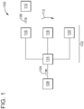
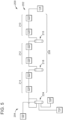
FIG. 1 depicts a schematic diagram of general of a liquefaction system not falling under the scope of the claims. -
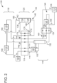
FIG. 2 depicts a schematic diagram of an example of the present invention for use in the liquefaction system ofFIG. 1 ; -
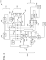
FIG. 3 depicts a schematic diagram of an example of the present invention for use in the liquefaction system ofFIG. 1 ; -
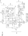
FIG. 4 depicts a schematic diagram of an example of the present invention for use in the liquefaction system ofFIG. 1 ; -
FIG. 5 depicts a schematic diagram of an example of a compression circuit for use in the liquefaction system ofFIGS. 1 ,2 ,3 , and4 ; -
FIG. 6 depicts a schematic diagram of an example of a compression circuit for use in the liquefaction system ofFIGS. 1 ,2 ,3 , and4 ; and -
FIG. 7 depicts a flow diagram of an exemplary embodiment of a liquefaction process. - Where applicable like reference characters designate identical or corresponding components and units throughout the several views, which are not to scale unless otherwise indicated. The embodiments disclosed herein may include elements that appear in one or more of the several views or in combinations of the several views. Moreover, methods are exemplary only and may be modified by, for example, reordering, adding, removing, and/or altering the individual stages.
- The discussion below describes various embodiments that are useful to process hydrocarbons for storage as liquid natural gas (LNG). These embodiments include a fluid circuit that flashes and then cools the circulating hydrocarbon stream at an intermediate pressure between the "high" pressure of an incoming hydrocarbon feedstock and the "low" pressure of a boil-off gas that originates from a storage facility. Other embodiments are within the scope of the disclosed subject matter.
-
FIG. 1 illustrates a schematic diagram of a general liquefaction system 100 (also, "system 100") for use to liquefy a hydrocarbon stream not according to the invention. At a high level, thesystem 100 can have afluid circuit 102 that receives afeedstock 104 from asource 106. Incomingfeedstock 104 may be in vapor form (also, "gas" or "natural gas") with a composition that is predominantly methane. Embodiments of thesystem 100 may be compatible with compositions having methane in a first concentration that is approximately 93 % (930,000 ppmV) or greater. In use, thesystem 100 can form one or more products (e.g., a first product 108), typically liquid natural gas (LNG) that meets specifications that define parameters (e.g., temperature, pressure, composition, etc.) for storage. These specifications may specify a second concentration of methane for theLNG product 108 that is lower than the first concentration ofincoming feedstock 104. In one example, the second concentration of methane in thefirst product 108 for may be approximately 99 % or more (990,000 ppmV). Thefluid circuit 102 can distribute theLNG product 108 to astorage facility 110 and/or other collateral process equipment. - The
fluid circuit 102 may be configured to form and circulate fluids (e.g., gasses and liquids). For clarity, these fluids are identified inFIG. 1 as aprocess stream 112. In one implementation, thefluid circuit 102 may include a first heat exchanger 114 (also, "main heat exchanger 114"). Examples of themain heat exchanger 114 can have multiple passes, each in the form of a passage that may include brazed aluminum fins ("plate-fin exchanger") and/or tubular coils ("coil wound exchanger"). Such configurations can facilitate indirect exchange of thermal energy among the fluids that pass through themain heat exchanger 114. The passages can couple with or more processing units to exchange theprocess stream 112 at various temperatures. Examples of theprocess stream 112 can be in vapor, liquid, and mixed-phase forms. However, in one implementation, thefluid circuit 102 may be configured to maintain theprocess stream 112 in a single phase, either vapor phase or liquid phase. The processing units can be arranged as asub-cooling unit 116, acompression unit 118, and methane expander 120. -
FIG. 2 illustrates an example of the present invention for use in theliquefaction system 100 that renders theLNG product 108 fromincoming feedstock 104. At thesub-cooling unit 116, thefluid circuit 102 has afirst vessel 122 that couples with asecond heat exchanger 124. Examples of thesecond heat exchanger 124 can form three passes, although fewer or more passes may be useful in certain implementations of thesystem 100. Thefluid circuit 102 can form afluid path 126 that couples the passes of thesecond heat exchanger 124 together. In thecompression unit 118, thefluid circuit 102 incorporates afirst compression circuit 128 and asecond compression circuit 130, referred to collectively as the "recycle gas compression circuit." Thefirst compression circuit 128 can couple with thesub-cooling unit 116 via themain heat exchanger 114. Themethane expander 120 can be part of an open loop circuit or "recycle gas circuit" that provides the primary refrigeration at themain heat exchanger 114. This recycle gas circuit includes a turbo-machine 132 having a turbo-compressor 134 that is configured to operate in response to work from a turbo-expander 136. The turbo-machine 132 has a pair of inlets (afirst inlet 138 and a second inlet 140) and a pair of outlets (afirst outlet 142 and a second outlet 144). Theinlets outlets machine 132 with themain heat exchanger 114 and thefirst compression circuit 128. - The
fluid circuit 102 may benefit from one or more auxiliary or peripheral components that can facilitate processes to generate theLNG product 108. For example, thefluid circuit 102 includes one ormore throttling devices 146. Examples of thethrottling devices 146 can include valves (e.g., Joule-Thompson valves) and/or devices that are similarly situated to throttle the flow the process stream 112 (FIG. 1 ). In use, the throttlingdevices 146 are interposed between components in thefluid circuit 102 as necessary to achieve certain changes in fluid parameters (e.g., temperature, pressure, etc.). - The
compression circuits second compression circuit 130 may be independent or separate from the compression stages of thefirst compression circuit 128. This discussion does also contemplates applications for thesystem 100 that may benefit from combinations of the stages ofcompression circuits - Starting at the left side of the diagram in
FIG. 2 , thefluid circuit 102 can direct the process stream 112 (FIG. 1 ) through the various components to generate theLNG product 108. In one implementation,incoming feedstock 104 can enter a first pass of themain heat exchanger 114 at a first pressure and a first temperature, typically ambient temperature that prevails at thesystem 100 and/or the surrounding facility. The first pressure may depend on operation of the facility and/or installation. Exemplary pressure may be approximately 700 psig. But this disclosure contemplates that the embodiments can be tuned to accommodate pressure in a range of approximately 400 psig (2758 kPa) to approximately 1200 psig (8274 kPa).Incoming feedstock 104 exits the device (at 148) at a second temperature in a range from approximately - 140 °F (-96°C) to approximately -170 °F (-112°C). - The
fluid circuit 102 directs the cooledfluid stream 148 to a first throttling device (e.g., throttling device 146). This first throttling device "flashes" the cooledfluid stream 148 upstream of thefirst vessel 122, effectively reducing the pressure from the first pressure to the intermediate pressure mentioned above. This intermediate pressure corresponds with suction pressure for one or more of the stages of thecompression circuits second compression circuit 130. Flashing at this intermediate pressure is beneficial to simplify construction of thesystem 100. In one implementation, the cooledfluid stream 148 may exit the first throttling device (at 150) so that the intermediate pressure is less than the first pressure, for example, in a range of approximately 200 psig (1379 kPa) to approximately 250 psig (1724 kPa) and at a temperature from approximately -170 °F (-112°C) to approximately -200 °F (-129°C). - The
fluid circuit 102 can direct the flashedstream 150 at the reduced pressure and, where applicable, reduced temperature to thefirst vessel 122. Processes in thefirst vessel 122 separate flashedstream 150 at the intermediate pressure (and in mixed-phase form) into a top product and a bottom product, one each in vapor form and liquid form, respectively. Thefluid circuit 102 directs the liquid bottom product to a first pass of thesecond heat exchanger 124. This first pass further reduces the temperature of the liquid bottom product so that the liquid bottom product is at (or near) the storage pressure of the storage tank at thestorage facility 110. Typical "storage" pressure for thesystem 100 may be approximately 28 psig (193 kPa). But such values may depend on specifications at thestorage facility 110 that can call for "storage" pressure from approximately 1 psig (6.89 kPa) (or "unpressurized") to approximately 30 psig (207 kPa) ("pressurized") or more. In one implementation, the liquid bottom product exits the first pass of thesecond heat exchanger 124 in a range from approximately -245 °F (-154°C) to approximately -260 °F (-162°C). - The
fluid circuit 102 splits the liquid bottom product into one or more portions downstream of thesecond heat exchanger 124. Thefluid circuit 102 directs a first portion as theLNG product 108 for storage in thestorage facility 110. Thefluid circuit 102 directs a second portion, or "slip stream," back to a second pass of thesecond heat exchanger 124 via thefluid path 126. Thefluid circuit 102 includes a second throttling device (e.g., throttling device 146) interposed between the first pass and the second pass of thesecond heat exchanger 124. This second throttling device is configured to flash the slip stream so that the slip stream exits the device (at 154) at a pressure that is below the "storage" pressure. This pressure can be a range of approximately 25 psig (172 kPa) to approximately 10 psig (69 kPa). - The
fluid circuit 102 also couples thesub-cooling unit 116 with thestorage facility 110. This configuration directs astream 156 to a third pass of thesecond heat exchanger 124. Thestream 156 includes boil-off vapor from a storage tank at thestorage facility 110, although the vapor may result from processing of fluids that occur at thestorage facility 110. - The second pass and the third pass are useful to sub-cool the
slip stream 154 and boil-off stream 156. During operation, and as noted above, each of theslip stream 154 and the boil-off stream 156 can be conditioned upstream of thesecond heat exchanger 124 to pressure below the "storage" pressure, e.g., of the storage tank at thestorage facility 110. Theslip stream 154 may exit the second pass of thesecond heat exchanger 124 as vapor (at 158) at a temperature from approximately -175 °F (-115°C) to approximately -190 °F (-123°C). The boil-off stream 156 may exit the third pass of the heat exchanger 124 (at 160) at a temperature of from approximately -175 °F (-115°C) to approximately -190 °F (-123°C). Thisfluid circuit 102 can be configured to combine thestream 158 and thestream 160 downstream of thesecond heat exchanger 124 and upstream ofmain heat exchanger 114. This combinedvapor stream main heat exchanger 114, as noted more below. - The
fluid circuit 102 directs the vapor top product stream from thefirst vessel 122 and the combinedvapor stream second heat exchanger 124 to thecompression unit 118. Preferably, these streams flow through separate passes of themain heat exchanger 114. In one implementation, the vapor top product stream from thefirst vessel 122 enters a second pass of themain heat exchanger 114. This stream may be useful to provide some of the cooling duty at themain heat exchanger 114. The combinedvapor stream second heat exchanger 124 enters a third pass of themain heat exchanger 114. Each of the second pass and the third pass warms the respective stream so that the streams exit the heat exchanger 114 (at 162, 164) at a temperature from approximately 90 °F (32°C) to approximately 120 °F (49°C). - The
fluid circuit 102 can couple the passes of themain heat exchanger 114 with different locations of thefirst compression circuit 128. This configuration uses the stream 164 (formed by the combinedvapor stream 158, 160) as make-up for thecompression circuits fluid circuit 102 can direct thestream 164 from the third pass to a first location that is upstream of each of the compression stages (e.g., of the first compression circuit 128).Vapor stream 162 from the second pass can enter at a second location, at an intermediate compression stage of the recycle gas compression circuit and, in one example, downstream of each of the compressions stages of thefirst compression circuit 128. In one implementation, thefirst compression circuit 128 can be configured so that a vapor stream exits the last of the compression stages (at 166) at a pressure from approximately 200 psig (1379 kPa) to approximately 250 psig (1724 kPa). This pressure may serve as the suction pressure for thesecond compression circuit 130. Thefluid circuit 102 can direct thevapor stream 166 at this pressure to thesecond compression circuit 130. This configuration is effective to compress thevapor stream 166 so as to exit the second compression circuit 130 (at 168) at its maximum pressure. In one implementation, the maximum pressure of thevapor stream 168 is approximately 1200 psig (8274 kPa) and, in one example, from approximately 1000 psig (6895 kPa) to approximately 1200 psig (8274 kPa). - The recycle gas compression circuit can embody an open loop circuit. This type of circuit can bleed-off a portion of the
compressed vapor stream 168 that exits thesecond compression circuit 130. This portion finds use as the primary cooling stream for themain heat exchanger 114. During operation, bleed-off may occur after the circuit builds up from continuous feed from thefirst vessel 122, thesecond heat exchanger 124, and discharge from the turbo-compressor 134. Thefluid circuit 102 is configured to split thecompressed vapor stream 168 to form two or more portions upstream of themain heat exchanger 114. The first portion can exit a fourth pass (at 170) as liquid at a temperature of from approximately -140 °F (-96°C) to approximately -170 °F (-112°C). Thefluid circuit 102 can direct thefirst portion 170 from the fourth pass to thefirst throttling device 146. Thefirst portion 170 may exit the first throttling device 146 (at 172) at the same pressure that the cooledfluid stream 148 exits the first throttling device (at 150), preferably from approximately 200 psig (1379 kPa) to approximately 250 psig (1724 kPa). Thefluid circuit 102 can, in turn, combine these two flashedstreams first vessel 122. - The second portion forms the primary cooling stream of the recycle gas circuit. As shown in
FIG. 2 , this second portion can exit a fifth pass (at 174) at a temperature of from approximately 20 °F (-6.7°C) to approximately 0 °F (-17.8°C) and, in one example, at approximately 13 °F (-10.6°C). Thefluid circuit 102 directs the cooledsecond portion 174 from the fifth pass to theinlet 140 of the turbo-expander 136. In one implementation, the turbo-expander 136 can be configured to decrease the pressure of the cooledsecond portion 174. This apparatus may operate so that the vapor stream exits the turbo-expander 136 (at 176) at a pressure from approximately 110 psig (758 kPa) to approximately 130 psig (896 kPa) and, in one example, the pressure is approximately 116 psig (800 kPa). Expansion at the turbo-expander 136 can result in the expandedvapor stream 176 having a temperature of -116 °F (-82°C), but this temperature can vary from approximately -180 °F (-118°C) to approximately -150 °F (-101°C). Thefluid circuit 102 can direct the expandedvapor stream 176 to a sixth pass of themain heat exchanger 114. As noted above, flow of the expandedvapor stream 176 through this sixth pass can provide the primary refrigeration for themain heat exchanger 114. The expanded vapor stream can exit the sixth pass (at 178) at a temperature from approximately 90 °F (32°C) to approximately 120 °F (49°C). As shown inFIG. 2 , thefluid circuit 102 can direct the resultingliquid stream 178 from the sixth pass to theinlet 138 of the turbo-compressor 134, which compresses the incoming fluid. In one implementation, theliquid stream 178 may exit the turbo-compressor 134 (at 180) at a pressure from approximately 200 psig (1379 kPa) to approximately 300 psig (2068 kPa). Thefluid circuit 102 can be configured to return thestream 180 to the second location on thecompression unit 118. -
FIG. 3 depicts another example of the present invention for use in theliquefaction system 100. Thefluid circuit 102 may include a cooler 182 interposed between thefirst compression circuit 128 and the turbo-compressor 134. Thefluid circuit 102 may also include aseparation unit 184 to remove impurities (e.g., heavy hydrocarbons) fromincoming feedstock 104. Examples of theseparation unit 184 may include a pair of vessels (e.g., asecond vessel 186 and a third vessel 188). Processes that occur at thevessels third vessel 188 may also benefit from use of one or more peripheral components (e.g., a peripheral component 190). Examples of theperipheral component 190 can include pumps, boilers, heaters, and like devices that can facilitate operation of one or more of thevessels peripheral component 190 may embody a boiler that couples thethird vessel 186 with apipeline 192 and/or like collateral equipment (e.g., conduit, tank, etc.). - The
fluid circuit 102 may be configured with the cooler 182 between the second location on thecompression circuits compressor 134. This configuration is useful to cool thestream 180 that exits the turbo-compressor 134. In one implementation, thestream 180 exist the cooler 182 so as to enter the second location of thecompression unit 118 at a temperature of approximately 111 °F (44°C). However, this temperature may vary within in a range from approximately 90 °F (32°C) to approximately 120 °F (49°C). - The
fluid circuit 102 may be configured to couple themain heat exchanger 114 with theseparation unit 184. This configuration can direct thestream 148 from the first pass to thesecond vessel 186. Depending on the composition of incoming feedstock 104 (and, correspondingly, the stream 148), thesecond vessel 186 can operate at pressure that is less than 700 psig (4826 kPa), although this operating pressure can vary in a range of from approximately 600 psig (4137 kPa) to approximately 800 psig (5515 kPa). In one implementation, thesecond vessel 186 operates at parameters (e.g., temperature, pressure, etc.) so that the vapor top product meets specifications that define the composition of theLNG product 108. - The
fluid circuit 102 can direct the liquid bottom product from thesecond vessel 186 to thethird vessel 188. Examples of thethird vessel 188 can operate as a stabilizer column to remove light hydrocarbons to form a liquid bottom product that is "stable" for storage. This liquid bottom product may be a liquid petroleum (LPG) product stabilized at propane vapor pressure. Operating parameters for thethird vessel 188 may designate a pressure equal to or slightly above the operating pressure of thefirst vessel 122. A third throttling device (e.g., throttling device 146) may be useful to reduce the pressure and/or temperature of the liquid bottom product upstream of thethird vessel 188. In one implementation, thethird vessel 188 operates at parameters (e.g., temperature, pressure, etc.) so that the vapor top product meets specifications that define the composition of theLNG product 108. The liquid bottom product can exit the third throttling device 146 (at 194) at a pressure from approximately 200 psig (1379 kPa) to approximately 300 psig (2068 kPa) and a temperature of from approximately - -90 °F (32°C) to approximately - -120 °F (49°C). Thefluid circuit 102 can be configured to direct the vapor top product from thestabilizer column 188 to thefirst vessel 122. - The
stabilizer column 188 can be fabricated from standard pipe size and schedule for use with a wide range of output rates. In one example, the stabilizer column can use twelve trays so that the top vapor product meets specifications for theLNG product 108. Thefluid circuit 102 may include a condenser, but such configuration may not be necessary because theincoming feedstock 110 may enter the stabilizer column at less than approximately - 100 °F (-73°C) and the vapor top product may exit the stabilizer column at - 30 °F (-34°C) or warmer. Theboiler 190 can use either hot oil or electricity to generate heat. For small re-boiler loads, an electric re-boiler may be cost effective for this purpose. - As noted above, the vapor top products from the
vessels LNG product 108. The vapor top product from thestabilizer column 188 may enter thesecond vessel 122. Thefluid circuit 102 can direct the vapor top product from thesecond vessel 186 to themain heat exchanger 114. In one implementation, the vapor top product from thesecond vessel 186 exits (at 196) a seventh pass as a liquid at a temperature in a range from approximately -175 °F (-115°C) to approximately -190 °F (-123°C). -
FIG. 4 depicts a further example of the present invention for use in thesystem 100 with components that might be useful to condition theLNG product 108, the boil-offvapor 156, and the LPG product. One or more of these components may be part of thefluid circuit 102 or found separately as part of, for example, thestorage facility 110, processing facility, and the like. The components may include additional throttling devices (e.g., throttling device 146) and coolers, although this disclosure does not require nor foreclose other devices that may be useful to condition fluids as contemplated herein. For example, a fourth throttling device may reduce the pressure of theLNG product 108 downstream of thesecond heat exchanger 124 and upstream of thestorage facility 110. A fifth throttling device may be used to condition the boil-offvapor 156 to a pressure approximately equal to the pressure of the slip stream (discussed above in connection with the sub-cooling unit 116). In one example, a cooler 198 and asixth throttling device 146 may condition the LPG product downstream of thestabilizer column 188. -
FIG. 5 depicts an example of acompression circuit 200. This example may find use to implement the compression circuit 128 (FIGS. 2 ,3 , and4 ). Thecompression circuit 200 has afirst end 202 and asecond end 204. Thefirst end 202 can couple with themain heat exchanger 114, preferably to the third pass to receive the combined vapor stream that may originate from thesub-cooling unit 116. Thesecond end 204 may couple with thesecond compression unit 130, with themain heat exchanger 114, as well as with the turbo-compressor 134 via, in one example, the cooler 182. - The
compression circuit 200 may be configured to increase the pressure without increasing the temperature of the process stream 112 (FIG. 1 ) from thefirst end 202 to thesecond end 204. This functionality may be embodied in various components (e.g., coolers, compressors, etc.). In one implementation, thecompression circuit 200 may include a first compression vessel at the first end 202 (or "inlet"). Examples of the vessel can embody a desuperheater or like device to reduce the temperature of incoming gas to make it less superheated. This device can couple with acompression path 208 that has one or more compression stages (e.g., afirst stage 210, asecond stage 212, and a third stage 214). Thecompression path 208 may include one or more compression vessels (e.g., asecond compression vessel 216 and a third compression vessel 218) interposed between thestages compressor 222. Examples of the cooler 220 may be air-cooled, although this disclosure does not limit selection to any particular type or variation for these devices. Thecompressor 222 may be gas, motor, and turbine driven devices that can maintain and/or raise the pressure of process stream 112 (FIG. 1 ) noted herein. At thesecond end 204, thecompression path 208 may include afourth compression vessel 224. This device can receive the compressed stream from thethird stage 220. In one implementation, thefourth compression vessel 224 can also receive each of the vapor top product from the first vessel 122 (FIGS. 2 ,3 , and4 ) and the compressed vapor stream from the turbo-compressor 134 (FIGS 2 ,3 , and4 ). Thecompression circuit 200 can deliver the vapor top product from thefourth compression vessel 224 to thesecond compression circuit 130. -
FIG. 6 depicts an example of acompression circuit 300. This example may find use to implement the compression circuit 130 (FIGS. 2 ,3 , and4 ). Thefirst end 302 can couple with thefirst compression circuit 128; as noted above, thecompression circuit 118 may be configured to direct the vapor top product from thefourth compression vessel 224 to thefirst stage 310. At thesecond end 304, thecompression circuit 300 can couple with themain heat exchanger 114, preferably to the fourth pass to deliver compressed vapor stream to the first throttling device. -
FIG. 7 depicts an example of aprocess 400 to liquefy an incoming natural gas stream. Theprocess 400 may leverage the structure discussed above in whole or in part. In one implementation, theprocess 400 may include, atstage 402, flashing a vapor stream derived from an incoming feedstock to a mixed-phase stream at a first pressure and, atstage 404, separating the mixed-phase stream into a first stream and a second stream. Theprocess 400 may also include, atstage 406, passing the second stream though a heat exchanger and, atstage 408, directing a first portion of the second stream to form a liquid natural gas (LNG) product. Theprocess 400 may include, atstage 410, flashing the second portion to a second pressure that is lower that the first pressure. As noted herein, this second pressure may correspond with storage pressure of boil-off gas from a storage facility so that theprocess 400 may include, atstage 412, mixing the second portion with boil-off gas that exits the heat exchanger. In one implementation, theprocess 400 may include, atstage 414, compressing the mixed stream in a compression circuit from the second pressure to a third pressure. This stage may include, atstage 416, compressing the mixed stream through a first compression circuit from the second pressure to a suction pressure and, at stage 418, compressing the mixed stream through a second compression circuit from the suction pressure to the third pressure. Theprocess 400 may further include, atstage 420, expanding the mixed stream from the third pressure to the first pressure and, atstage 422, re-introducing the mixed stream a the first pressure into the compression circuit. In one implementation, theprocess 400 may include, atstage 424, bleeding off part of the mixed stream at the third pressure, atstage 426, flashing the part to the first pressure, and at stage 428, mixing the part with the mixed phase stream at the first pressure before separating the mixed-phase stream into the first stream and the second stream (at stage 404). Further, theprocess 400 may include, atstage 430, separating the incoming feed stock into the vapor stream and a liquid petroleum (LPG) product prior to flashing (at stage 402). - As used herein, an element or function recited in the singular and proceeded with the word "a" or "an" should be understood as not excluding plural said elements or functions, unless such exclusion is explicitly recited. Furthermore, references to "one embodiment" of the claimed invention should not be interpreted as excluding the existence of additional embodiments that also incorporate the recited features.
- This written description uses examples to disclose the embodiments, including the best mode, and also to enable any person skilled in the art to practice the embodiments, including making and using any devices or systems and performing any incorporated methods. The patentable scope of the embodiments is defined by the claims.
- In view of the foregoing, some embodiments exhibit process efficiency that compares favorably with a nitrogen expander process but require more horsepower than an equivalent sized mixed refrigerant system as well as pressurized storage. Some embodiments require only a single expander to achieve these improvements. This requirement compares favorably with systems that employ two expanders that work in parallel. Moreover, unlike systems that implement mixed-refrigeration processes, some embodiments do not require refrigerants, thus eliminating the need for use, handling, and on-site storage of refrigerants.
Claims (4)
- A liquefaction process, comprising:flashing a vapor stream derived from an incoming hydrocarbon feedstock (104) received from a first heat exchanger (114) through a throttling device (146) to a mixed-phase stream at an intermediate pressure between a higher pressure of the incoming hydrocarbon feedstock (104) and a lower pressure of a boil-off gas that originated from a storage facility (110);separating the mixed-phase stream in a vessel (122) into a vapor first stream and a liquid second stream;passing the vapor first stream at the intermediate pressure through the first heat exchanger (114) into a compression unit (118);passing the liquid second stream through a second heat exchanger (124);splitting the liquid second stream into at least two portions downstream of the second heat exchanger (124);directing a first portion of the second stream to form a liquid natural gas (LNG) product into the storage facility (110);mixing a second portion of the second stream which is throttled (146) to the lower pressure and passed back through the second heat exchanger (124) with said boil-off gas from the storage facility (110) that also exits the second heat exchanger (124) to form a mixed stream;passing the mixed stream through the first heat exchanger (114) and introducing it into the compression unit (118), the compression unit (118) comprising a first compression circuit (128) and a second compression circuit (130) and (130),compressing the mixed stream from the lower pressure to a third pressure;passing a portion of the compressed mixed stream (168) that exits the second compression circuit (130) at the third pressure through the first heat exchanger (114);expanding the cooled portion of the compressed mixed stream from the third pressure in a turbo-expander (136), passing it back through the first heat exchanger (114), compressing it to the intermediate pressure in a turbo-compressor (134) which is configured to operate in response to work from the turbo-expander (136); andre-introducing the re-compressed portion of the mixed stream at the intermediate pressure into the compression unit (118);wherein the intermediate pressure corresponds with suction pressure internal to the compression unit (118).
- The liquefaction process of claim 1, further comprising:
compressing the mixed stream through the first compression circuit (128) from the lower pressure to suction pressure for the second compression circuit (130) downstream of the first compression circuit (128). - The liquefaction process of claim 2, further comprising:
compressing the mixed stream through the second compression circuit (130) from the suction pressure to the third pressure. - The liquefaction process of any preceding claim, further comprising:bleeding-off part (170) of the mixed stream at the third pressure;mixing the part with the mixed-phase stream at the intermediate pressure; andflashing the part of the mixed stream to the intermediate pressure.
Applications Claiming Priority (3)
| Application Number | Priority Date | Filing Date | Title |
|---|---|---|---|
| US201662291868P | 2016-02-05 | 2016-02-05 | |
| US15/356,591 US10760850B2 (en) | 2016-02-05 | 2016-11-20 | Gas liquefaction systems and methods |
| PCT/US2017/016476 WO2017136703A2 (en) | 2016-02-05 | 2017-02-03 | Gas liquefaction systems and methods |
Publications (2)
| Publication Number | Publication Date |
|---|---|
| EP3411645A2 EP3411645A2 (en) | 2018-12-12 |
| EP3411645B1 true EP3411645B1 (en) | 2024-07-10 |
Family
ID=59497552
Family Applications (1)
| Application Number | Title | Priority Date | Filing Date |
|---|---|---|---|
| EP17704971.5A Active EP3411645B1 (en) | 2016-02-05 | 2017-02-03 | Gas liquefaction process |
Country Status (5)
| Country | Link |
|---|---|
| US (1) | US10760850B2 (en) |
| EP (1) | EP3411645B1 (en) |
| CN (1) | CN108779952B (en) |
| AU (2) | AU2017200487B2 (en) |
| WO (1) | WO2017136703A2 (en) |
Families Citing this family (4)
| Publication number | Priority date | Publication date | Assignee | Title |
|---|---|---|---|---|
| JP6366870B1 (en) * | 2018-01-17 | 2018-08-01 | レール・リキード−ソシエテ・アノニム・プール・レテュード・エ・レクスプロワタシオン・デ・プロセデ・ジョルジュ・クロード | Boil-off gas reliquefaction device and LNG supply system including the same |
| FR3125115B1 (en) * | 2021-07-08 | 2024-05-10 | Air Liquide | Hydrogen liquefaction installation and process. |
| US20230366619A1 (en) * | 2022-05-10 | 2023-11-16 | High Roller E & C, LLC | LNG Liquefaction System and Process |
| US12474114B2 (en) | 2022-10-14 | 2025-11-18 | Honeywell Lng Llc | Semi-open loop liquefaction process |
Family Cites Families (14)
| Publication number | Priority date | Publication date | Assignee | Title |
|---|---|---|---|---|
| US3677019A (en) | 1969-08-01 | 1972-07-18 | Union Carbide Corp | Gas liquefaction process and apparatus |
| US4040806A (en) | 1972-01-19 | 1977-08-09 | Kennedy Kenneth B | Process for purifying hydrocarbon gas streams |
| US4435198A (en) * | 1982-02-24 | 1984-03-06 | Phillips Petroleum Company | Separation of nitrogen from natural gas |
| GB8418840D0 (en) | 1984-07-24 | 1984-08-30 | Boc Group Plc | Gas refrigeration |
| JP3213846B2 (en) | 1991-01-25 | 2001-10-02 | 日本酸素株式会社 | Supercritical gas liquefaction method and apparatus |
| JP3869854B2 (en) | 1995-10-05 | 2007-01-17 | ビーエイチピー ペトロリウム ピーティーワイ リミテッド | Liquefaction device |
| US5755114A (en) | 1997-01-06 | 1998-05-26 | Abb Randall Corporation | Use of a turboexpander cycle in liquefied natural gas process |
| US6658890B1 (en) | 2002-11-13 | 2003-12-09 | Conocophillips Company | Enhanced methane flash system for natural gas liquefaction |
| US20070283718A1 (en) | 2006-06-08 | 2007-12-13 | Hulsey Kevin H | Lng system with optimized heat exchanger configuration |
| US10113127B2 (en) * | 2010-04-16 | 2018-10-30 | Black & Veatch Holding Company | Process for separating nitrogen from a natural gas stream with nitrogen stripping in the production of liquefied natural gas |
| EP2598815A2 (en) * | 2010-07-28 | 2013-06-05 | Air Products and Chemicals, Inc. | Integrated liquid storage |
| FR2972792B1 (en) * | 2011-03-16 | 2017-12-01 | L'air Liquide Sa Pour L'etude Et L'exploitation Des Procedes Georges Claude | METHOD AND APPARATUS FOR CO2 LIQUEFACTION |
| WO2013028363A1 (en) | 2011-08-10 | 2013-02-28 | Conocophillips Company | Liquefied natural gas plant with ethylene independent heavies recovery system |
| CN104321581B (en) * | 2011-12-02 | 2016-10-19 | 氟石科技公司 | LNG boil-off gas recondensation configuration and method |
-
2016
- 2016-11-20 US US15/356,591 patent/US10760850B2/en active Active
-
2017
- 2017-01-25 AU AU2017200487A patent/AU2017200487B2/en active Active
- 2017-02-03 EP EP17704971.5A patent/EP3411645B1/en active Active
- 2017-02-03 CN CN201780009920.1A patent/CN108779952B/en not_active Expired - Fee Related
- 2017-02-03 WO PCT/US2017/016476 patent/WO2017136703A2/en not_active Ceased
-
2023
- 2023-01-19 AU AU2023200283A patent/AU2023200283B2/en active Active
Also Published As
| Publication number | Publication date |
|---|---|
| WO2017136703A2 (en) | 2017-08-10 |
| AU2023200283B2 (en) | 2024-08-15 |
| CA3012830A1 (en) | 2017-08-10 |
| AU2017200487A1 (en) | 2017-08-24 |
| AU2017200487B2 (en) | 2022-10-20 |
| WO2017136703A3 (en) | 2017-09-14 |
| EP3411645A2 (en) | 2018-12-12 |
| CN108779952B (en) | 2021-12-31 |
| US10760850B2 (en) | 2020-09-01 |
| AU2023200283A1 (en) | 2023-02-23 |
| US20170227283A1 (en) | 2017-08-10 |
| CN108779952A (en) | 2018-11-09 |
Similar Documents
| Publication | Publication Date | Title |
|---|---|---|
| AU2023200283B2 (en) | Gas liquefaction system and methods | |
| US11136104B2 (en) | Ship | |
| AU2017232113B2 (en) | Mixed refrigerant cooling process and system | |
| RU2730090C2 (en) | Method and system for liquefaction of natural gas feed flow | |
| KR101966980B1 (en) | Refrigerant recursion line and liquefaction system comprising the same | |
| CA2984144C (en) | Preparing hydrocarbon streams for storage | |
| US12005999B2 (en) | Ship | |
| AU2007310940A1 (en) | Method and apparatus for liquefying hydrocarbon streams | |
| AU2023200787B2 (en) | Gas liquefaction system and methods | |
| KR20120005158A (en) | Natural gas liquefaction method and apparatus | |
| CA3012830C (en) | Gas liquefaction systems and methods | |
| CA2995844C (en) | Gas liquefaction system and methods | |
| AU2017200185B2 (en) | Reducing refrigeration duty on a refrigeration unit in a gas processing system | |
| KR20160149399A (en) | Vessel Including Storage Tanks |
Legal Events
| Date | Code | Title | Description |
|---|---|---|---|
| STAA | Information on the status of an ep patent application or granted ep patent |
Free format text: STATUS: UNKNOWN |
|
| STAA | Information on the status of an ep patent application or granted ep patent |
Free format text: STATUS: THE INTERNATIONAL PUBLICATION HAS BEEN MADE |
|
| PUAI | Public reference made under article 153(3) epc to a published international application that has entered the european phase |
Free format text: ORIGINAL CODE: 0009012 |
|
| STAA | Information on the status of an ep patent application or granted ep patent |
Free format text: STATUS: REQUEST FOR EXAMINATION WAS MADE |
|
| 17P | Request for examination filed |
Effective date: 20180905 |
|
| AK | Designated contracting states |
Kind code of ref document: A2 Designated state(s): AL AT BE BG CH CY CZ DE DK EE ES FI FR GB GR HR HU IE IS IT LI LT LU LV MC MK MT NL NO PL PT RO RS SE SI SK SM TR |
|
| AX | Request for extension of the european patent |
Extension state: BA ME |
|
| DAV | Request for validation of the european patent (deleted) | ||
| DAX | Request for extension of the european patent (deleted) | ||
| STAA | Information on the status of an ep patent application or granted ep patent |
Free format text: STATUS: EXAMINATION IS IN PROGRESS |
|
| 17Q | First examination report despatched |
Effective date: 20200529 |
|
| P01 | Opt-out of the competence of the unified patent court (upc) registered |
Effective date: 20230526 |
|
| GRAP | Despatch of communication of intention to grant a patent |
Free format text: ORIGINAL CODE: EPIDOSNIGR1 |
|
| STAA | Information on the status of an ep patent application or granted ep patent |
Free format text: STATUS: GRANT OF PATENT IS INTENDED |
|
| INTG | Intention to grant announced |
Effective date: 20240214 |
|
| GRAS | Grant fee paid |
Free format text: ORIGINAL CODE: EPIDOSNIGR3 |
|
| GRAA | (expected) grant |
Free format text: ORIGINAL CODE: 0009210 |
|
| STAA | Information on the status of an ep patent application or granted ep patent |
Free format text: STATUS: THE PATENT HAS BEEN GRANTED |
|
| AK | Designated contracting states |
Kind code of ref document: B1 Designated state(s): AL AT BE BG CH CY CZ DE DK EE ES FI FR GB GR HR HU IE IS IT LI LT LU LV MC MK MT NL NO PL PT RO RS SE SI SK SM TR |
|
| RAP3 | Party data changed (applicant data changed or rights of an application transferred) |
Owner name: BAKER HUGHES ENERGY SERVICES LLC |
|
| REG | Reference to a national code |
Ref country code: CH Ref legal event code: EP |
|
| REG | Reference to a national code |
Ref country code: DE Ref legal event code: R096 Ref document number: 602017083164 Country of ref document: DE |
|
| REG | Reference to a national code |
Ref country code: LT Ref legal event code: MG9D |
|
| REG | Reference to a national code |
Ref country code: NL Ref legal event code: MP Effective date: 20240710 |
|
| PG25 | Lapsed in a contracting state [announced via postgrant information from national office to epo] |
Ref country code: PT Free format text: LAPSE BECAUSE OF FAILURE TO SUBMIT A TRANSLATION OF THE DESCRIPTION OR TO PAY THE FEE WITHIN THE PRESCRIBED TIME-LIMIT Effective date: 20241111 |
|
| REG | Reference to a national code |
Ref country code: AT Ref legal event code: MK05 Ref document number: 1702350 Country of ref document: AT Kind code of ref document: T Effective date: 20240710 |
|
| PG25 | Lapsed in a contracting state [announced via postgrant information from national office to epo] |
Ref country code: NL Free format text: LAPSE BECAUSE OF FAILURE TO SUBMIT A TRANSLATION OF THE DESCRIPTION OR TO PAY THE FEE WITHIN THE PRESCRIBED TIME-LIMIT Effective date: 20240710 |
|
| PG25 | Lapsed in a contracting state [announced via postgrant information from national office to epo] |
Ref country code: PT Free format text: LAPSE BECAUSE OF FAILURE TO SUBMIT A TRANSLATION OF THE DESCRIPTION OR TO PAY THE FEE WITHIN THE PRESCRIBED TIME-LIMIT Effective date: 20241111 Ref country code: NL Free format text: LAPSE BECAUSE OF FAILURE TO SUBMIT A TRANSLATION OF THE DESCRIPTION OR TO PAY THE FEE WITHIN THE PRESCRIBED TIME-LIMIT Effective date: 20240710 |
|
| PG25 | Lapsed in a contracting state [announced via postgrant information from national office to epo] |
Ref country code: NO Free format text: LAPSE BECAUSE OF FAILURE TO SUBMIT A TRANSLATION OF THE DESCRIPTION OR TO PAY THE FEE WITHIN THE PRESCRIBED TIME-LIMIT Effective date: 20241010 |
|
| PG25 | Lapsed in a contracting state [announced via postgrant information from national office to epo] |
Ref country code: GR Free format text: LAPSE BECAUSE OF FAILURE TO SUBMIT A TRANSLATION OF THE DESCRIPTION OR TO PAY THE FEE WITHIN THE PRESCRIBED TIME-LIMIT Effective date: 20241011 Ref country code: PL Free format text: LAPSE BECAUSE OF FAILURE TO SUBMIT A TRANSLATION OF THE DESCRIPTION OR TO PAY THE FEE WITHIN THE PRESCRIBED TIME-LIMIT Effective date: 20240710 Ref country code: FI Free format text: LAPSE BECAUSE OF FAILURE TO SUBMIT A TRANSLATION OF THE DESCRIPTION OR TO PAY THE FEE WITHIN THE PRESCRIBED TIME-LIMIT Effective date: 20240710 |
|
| PG25 | Lapsed in a contracting state [announced via postgrant information from national office to epo] |
Ref country code: BG Free format text: LAPSE BECAUSE OF FAILURE TO SUBMIT A TRANSLATION OF THE DESCRIPTION OR TO PAY THE FEE WITHIN THE PRESCRIBED TIME-LIMIT Effective date: 20240710 |
|
| PG25 | Lapsed in a contracting state [announced via postgrant information from national office to epo] |
Ref country code: LV Free format text: LAPSE BECAUSE OF FAILURE TO SUBMIT A TRANSLATION OF THE DESCRIPTION OR TO PAY THE FEE WITHIN THE PRESCRIBED TIME-LIMIT Effective date: 20240710 |
|
| PG25 | Lapsed in a contracting state [announced via postgrant information from national office to epo] |
Ref country code: IS Free format text: LAPSE BECAUSE OF FAILURE TO SUBMIT A TRANSLATION OF THE DESCRIPTION OR TO PAY THE FEE WITHIN THE PRESCRIBED TIME-LIMIT Effective date: 20241110 Ref country code: AT Free format text: LAPSE BECAUSE OF FAILURE TO SUBMIT A TRANSLATION OF THE DESCRIPTION OR TO PAY THE FEE WITHIN THE PRESCRIBED TIME-LIMIT Effective date: 20240710 |
|
| PG25 | Lapsed in a contracting state [announced via postgrant information from national office to epo] |
Ref country code: HR Free format text: LAPSE BECAUSE OF FAILURE TO SUBMIT A TRANSLATION OF THE DESCRIPTION OR TO PAY THE FEE WITHIN THE PRESCRIBED TIME-LIMIT Effective date: 20240710 |
|
| PG25 | Lapsed in a contracting state [announced via postgrant information from national office to epo] |
Ref country code: ES Free format text: LAPSE BECAUSE OF FAILURE TO SUBMIT A TRANSLATION OF THE DESCRIPTION OR TO PAY THE FEE WITHIN THE PRESCRIBED TIME-LIMIT Effective date: 20240710 Ref country code: RS Free format text: LAPSE BECAUSE OF FAILURE TO SUBMIT A TRANSLATION OF THE DESCRIPTION OR TO PAY THE FEE WITHIN THE PRESCRIBED TIME-LIMIT Effective date: 20241010 |
|
| PG25 | Lapsed in a contracting state [announced via postgrant information from national office to epo] |
Ref country code: RS Free format text: LAPSE BECAUSE OF FAILURE TO SUBMIT A TRANSLATION OF THE DESCRIPTION OR TO PAY THE FEE WITHIN THE PRESCRIBED TIME-LIMIT Effective date: 20241010 Ref country code: PL Free format text: LAPSE BECAUSE OF FAILURE TO SUBMIT A TRANSLATION OF THE DESCRIPTION OR TO PAY THE FEE WITHIN THE PRESCRIBED TIME-LIMIT Effective date: 20240710 Ref country code: NO Free format text: LAPSE BECAUSE OF FAILURE TO SUBMIT A TRANSLATION OF THE DESCRIPTION OR TO PAY THE FEE WITHIN THE PRESCRIBED TIME-LIMIT Effective date: 20241010 Ref country code: LV Free format text: LAPSE BECAUSE OF FAILURE TO SUBMIT A TRANSLATION OF THE DESCRIPTION OR TO PAY THE FEE WITHIN THE PRESCRIBED TIME-LIMIT Effective date: 20240710 Ref country code: IS Free format text: LAPSE BECAUSE OF FAILURE TO SUBMIT A TRANSLATION OF THE DESCRIPTION OR TO PAY THE FEE WITHIN THE PRESCRIBED TIME-LIMIT Effective date: 20241110 Ref country code: HR Free format text: LAPSE BECAUSE OF FAILURE TO SUBMIT A TRANSLATION OF THE DESCRIPTION OR TO PAY THE FEE WITHIN THE PRESCRIBED TIME-LIMIT Effective date: 20240710 Ref country code: GR Free format text: LAPSE BECAUSE OF FAILURE TO SUBMIT A TRANSLATION OF THE DESCRIPTION OR TO PAY THE FEE WITHIN THE PRESCRIBED TIME-LIMIT Effective date: 20241011 Ref country code: FI Free format text: LAPSE BECAUSE OF FAILURE TO SUBMIT A TRANSLATION OF THE DESCRIPTION OR TO PAY THE FEE WITHIN THE PRESCRIBED TIME-LIMIT Effective date: 20240710 Ref country code: ES Free format text: LAPSE BECAUSE OF FAILURE TO SUBMIT A TRANSLATION OF THE DESCRIPTION OR TO PAY THE FEE WITHIN THE PRESCRIBED TIME-LIMIT Effective date: 20240710 Ref country code: BG Free format text: LAPSE BECAUSE OF FAILURE TO SUBMIT A TRANSLATION OF THE DESCRIPTION OR TO PAY THE FEE WITHIN THE PRESCRIBED TIME-LIMIT Effective date: 20240710 Ref country code: AT Free format text: LAPSE BECAUSE OF FAILURE TO SUBMIT A TRANSLATION OF THE DESCRIPTION OR TO PAY THE FEE WITHIN THE PRESCRIBED TIME-LIMIT Effective date: 20240710 |
|
| REG | Reference to a national code |
Ref country code: DE Ref legal event code: R097 Ref document number: 602017083164 Country of ref document: DE |
|
| PG25 | Lapsed in a contracting state [announced via postgrant information from national office to epo] |
Ref country code: DK Free format text: LAPSE BECAUSE OF FAILURE TO SUBMIT A TRANSLATION OF THE DESCRIPTION OR TO PAY THE FEE WITHIN THE PRESCRIBED TIME-LIMIT Effective date: 20240710 Ref country code: SM Free format text: LAPSE BECAUSE OF FAILURE TO SUBMIT A TRANSLATION OF THE DESCRIPTION OR TO PAY THE FEE WITHIN THE PRESCRIBED TIME-LIMIT Effective date: 20240710 Ref country code: RO Free format text: LAPSE BECAUSE OF FAILURE TO SUBMIT A TRANSLATION OF THE DESCRIPTION OR TO PAY THE FEE WITHIN THE PRESCRIBED TIME-LIMIT Effective date: 20240710 |
|
| PG25 | Lapsed in a contracting state [announced via postgrant information from national office to epo] |
Ref country code: EE Free format text: LAPSE BECAUSE OF FAILURE TO SUBMIT A TRANSLATION OF THE DESCRIPTION OR TO PAY THE FEE WITHIN THE PRESCRIBED TIME-LIMIT Effective date: 20240710 |
|
| PG25 | Lapsed in a contracting state [announced via postgrant information from national office to epo] |
Ref country code: CZ Free format text: LAPSE BECAUSE OF FAILURE TO SUBMIT A TRANSLATION OF THE DESCRIPTION OR TO PAY THE FEE WITHIN THE PRESCRIBED TIME-LIMIT Effective date: 20240710 |
|
| PGFP | Annual fee paid to national office [announced via postgrant information from national office to epo] |
Ref country code: FR Payment date: 20250321 Year of fee payment: 10 |
|
| PG25 | Lapsed in a contracting state [announced via postgrant information from national office to epo] |
Ref country code: SK Free format text: LAPSE BECAUSE OF FAILURE TO SUBMIT A TRANSLATION OF THE DESCRIPTION OR TO PAY THE FEE WITHIN THE PRESCRIBED TIME-LIMIT Effective date: 20240710 |
|
| PLBE | No opposition filed within time limit |
Free format text: ORIGINAL CODE: 0009261 |
|
| STAA | Information on the status of an ep patent application or granted ep patent |
Free format text: STATUS: NO OPPOSITION FILED WITHIN TIME LIMIT |
|
| 26N | No opposition filed |
Effective date: 20250411 |
|
| PG25 | Lapsed in a contracting state [announced via postgrant information from national office to epo] |
Ref country code: SE Free format text: LAPSE BECAUSE OF FAILURE TO SUBMIT A TRANSLATION OF THE DESCRIPTION OR TO PAY THE FEE WITHIN THE PRESCRIBED TIME-LIMIT Effective date: 20240710 |
|
| PG25 | Lapsed in a contracting state [announced via postgrant information from national office to epo] |
Ref country code: MC Free format text: LAPSE BECAUSE OF FAILURE TO SUBMIT A TRANSLATION OF THE DESCRIPTION OR TO PAY THE FEE WITHIN THE PRESCRIBED TIME-LIMIT Effective date: 20240710 |
|
| REG | Reference to a national code |
Ref country code: CH Ref legal event code: PL |
|
| PG25 | Lapsed in a contracting state [announced via postgrant information from national office to epo] |
Ref country code: LU Free format text: LAPSE BECAUSE OF NON-PAYMENT OF DUE FEES Effective date: 20250203 |
|
| PG25 | Lapsed in a contracting state [announced via postgrant information from national office to epo] |
Ref country code: CH Free format text: LAPSE BECAUSE OF NON-PAYMENT OF DUE FEES Effective date: 20250228 |
|
| REG | Reference to a national code |
Ref country code: BE Ref legal event code: MM Effective date: 20250228 |
|
| PG25 | Lapsed in a contracting state [announced via postgrant information from national office to epo] |
Ref country code: BE Free format text: LAPSE BECAUSE OF NON-PAYMENT OF DUE FEES Effective date: 20250228 |
|
| PG25 | Lapsed in a contracting state [announced via postgrant information from national office to epo] |
Ref country code: IE Free format text: LAPSE BECAUSE OF NON-PAYMENT OF DUE FEES Effective date: 20250203 |
|
| PGFP | Annual fee paid to national office [announced via postgrant information from national office to epo] |
Ref country code: GB Payment date: 20260121 Year of fee payment: 10 |
|
| PGFP | Annual fee paid to national office [announced via postgrant information from national office to epo] |
Ref country code: DE Payment date: 20260121 Year of fee payment: 10 |
|
| PGFP | Annual fee paid to national office [announced via postgrant information from national office to epo] |
Ref country code: IT Payment date: 20260121 Year of fee payment: 10 |