EP3410741A1 - Speaker - Google Patents
Speaker Download PDFInfo
- Publication number
- EP3410741A1 EP3410741A1 EP18174877.3A EP18174877A EP3410741A1 EP 3410741 A1 EP3410741 A1 EP 3410741A1 EP 18174877 A EP18174877 A EP 18174877A EP 3410741 A1 EP3410741 A1 EP 3410741A1
- Authority
- EP
- European Patent Office
- Prior art keywords
- bobbin
- vibration plate
- fixed
- speaker
- opening end
- Prior art date
- Legal status (The legal status is an assumption and is not a legal conclusion. Google has not performed a legal analysis and makes no representation as to the accuracy of the status listed.)
- Ceased
Links
Images




Classifications
-
- H—ELECTRICITY
- H04—ELECTRIC COMMUNICATION TECHNIQUE
- H04R—LOUDSPEAKERS, MICROPHONES, GRAMOPHONE PICK-UPS OR LIKE ACOUSTIC ELECTROMECHANICAL TRANSDUCERS; ELECTRIC HEARING AIDS; PUBLIC ADDRESS SYSTEMS
- H04R9/00—Transducers of moving-coil, moving-strip, or moving-wire type
- H04R9/06—Loudspeakers
-
- H—ELECTRICITY
- H04—ELECTRIC COMMUNICATION TECHNIQUE
- H04R—LOUDSPEAKERS, MICROPHONES, GRAMOPHONE PICK-UPS OR LIKE ACOUSTIC ELECTROMECHANICAL TRANSDUCERS; ELECTRIC HEARING AIDS; PUBLIC ADDRESS SYSTEMS
- H04R1/00—Details of transducers, loudspeakers or microphones
- H04R1/20—Arrangements for obtaining desired frequency or directional characteristics
- H04R1/22—Arrangements for obtaining desired frequency or directional characteristics for obtaining desired frequency characteristic only
- H04R1/28—Transducer mountings or enclosures modified by provision of mechanical or acoustic impedances, e.g. resonator, damping means
- H04R1/2869—Reduction of undesired resonances, i.e. standing waves within enclosure, or of undesired vibrations, i.e. of the enclosure itself
- H04R1/2876—Reduction of undesired resonances, i.e. standing waves within enclosure, or of undesired vibrations, i.e. of the enclosure itself by means of damping material, e.g. as cladding
- H04R1/288—Reduction of undesired resonances, i.e. standing waves within enclosure, or of undesired vibrations, i.e. of the enclosure itself by means of damping material, e.g. as cladding for loudspeaker transducers
-
- H—ELECTRICITY
- H04—ELECTRIC COMMUNICATION TECHNIQUE
- H04R—LOUDSPEAKERS, MICROPHONES, GRAMOPHONE PICK-UPS OR LIKE ACOUSTIC ELECTROMECHANICAL TRANSDUCERS; ELECTRIC HEARING AIDS; PUBLIC ADDRESS SYSTEMS
- H04R7/00—Diaphragms for electromechanical transducers; Cones
- H04R7/02—Diaphragms for electromechanical transducers; Cones characterised by the construction
- H04R7/12—Non-planar diaphragms or cones
- H04R7/127—Non-planar diaphragms or cones dome-shaped
-
- H—ELECTRICITY
- H04—ELECTRIC COMMUNICATION TECHNIQUE
- H04R—LOUDSPEAKERS, MICROPHONES, GRAMOPHONE PICK-UPS OR LIKE ACOUSTIC ELECTROMECHANICAL TRANSDUCERS; ELECTRIC HEARING AIDS; PUBLIC ADDRESS SYSTEMS
- H04R7/00—Diaphragms for electromechanical transducers; Cones
- H04R7/16—Mounting or tensioning of diaphragms or cones
- H04R7/18—Mounting or tensioning of diaphragms or cones at the periphery
-
- H—ELECTRICITY
- H04—ELECTRIC COMMUNICATION TECHNIQUE
- H04R—LOUDSPEAKERS, MICROPHONES, GRAMOPHONE PICK-UPS OR LIKE ACOUSTIC ELECTROMECHANICAL TRANSDUCERS; ELECTRIC HEARING AIDS; PUBLIC ADDRESS SYSTEMS
- H04R9/00—Transducers of moving-coil, moving-strip, or moving-wire type
- H04R9/02—Details
- H04R9/025—Magnetic circuit
-
- H—ELECTRICITY
- H04—ELECTRIC COMMUNICATION TECHNIQUE
- H04R—LOUDSPEAKERS, MICROPHONES, GRAMOPHONE PICK-UPS OR LIKE ACOUSTIC ELECTROMECHANICAL TRANSDUCERS; ELECTRIC HEARING AIDS; PUBLIC ADDRESS SYSTEMS
- H04R2400/00—Loudspeakers
- H04R2400/11—Aspects regarding the frame of loudspeaker transducers
-
- H—ELECTRICITY
- H04—ELECTRIC COMMUNICATION TECHNIQUE
- H04R—LOUDSPEAKERS, MICROPHONES, GRAMOPHONE PICK-UPS OR LIKE ACOUSTIC ELECTROMECHANICAL TRANSDUCERS; ELECTRIC HEARING AIDS; PUBLIC ADDRESS SYSTEMS
- H04R31/00—Apparatus or processes specially adapted for the manufacture of transducers or diaphragms therefor
- H04R31/006—Interconnection of transducer parts
-
- H—ELECTRICITY
- H04—ELECTRIC COMMUNICATION TECHNIQUE
- H04R—LOUDSPEAKERS, MICROPHONES, GRAMOPHONE PICK-UPS OR LIKE ACOUSTIC ELECTROMECHANICAL TRANSDUCERS; ELECTRIC HEARING AIDS; PUBLIC ADDRESS SYSTEMS
- H04R7/00—Diaphragms for electromechanical transducers; Cones
- H04R7/02—Diaphragms for electromechanical transducers; Cones characterised by the construction
- H04R7/12—Non-planar diaphragms or cones
-
- H—ELECTRICITY
- H04—ELECTRIC COMMUNICATION TECHNIQUE
- H04R—LOUDSPEAKERS, MICROPHONES, GRAMOPHONE PICK-UPS OR LIKE ACOUSTIC ELECTROMECHANICAL TRANSDUCERS; ELECTRIC HEARING AIDS; PUBLIC ADDRESS SYSTEMS
- H04R9/00—Transducers of moving-coil, moving-strip, or moving-wire type
- H04R9/02—Details
- H04R9/04—Construction, mounting, or centering of coil
- H04R9/041—Centering
- H04R9/043—Inner suspension or damper, e.g. spider
Definitions
- the present invention relates to a speaker in which an inner peripheral edge of a vibration plate is fixed to a bobbin having a voice coil wound thereon and the bobbin and the vibration plate are driven by a current flowing in the voice coil and a magnetic field of a magnetic circuit portion.
- a voice coil is wound on a bobbin and magnetic energy of a magnetic circuit portion is transmitted to the voice coil so that the magnetic energy is converted into kinetic energy of the voice coil and the bobbin. Further, a vibration is transmitted from the bobbin to a vibration plate and sound energy is emitted into a space from the vibration plate.
- the rigidity of the bobbin transmitting the kinetic energy is low, distortion and extra vibration are likely to occur in the bobbin.
- the bobbin of the vibration plate fixed portion is easily deformed. As a result, a decrease in sound pressure and nonlinear distortion are likely to occur in the sound emitted from the vibration plate.
- a method of forming a part or the entirety of the bobbin of a metal material such as titanium or aluminum is considered in order to improve the rigidity of the bobbin.
- a metal material such as titanium or aluminum
- Patent Literature 1 A structure of a conventional speaker is shown in Patent Literature 1 below.
- a cone-shaped vibration plate is fixed to an outer surface of an intermediate portion away from an opening end portion of a bobbin on which a voice coil is wound and a dust cap is fixed to the opening end portion of the bobbin.
- Patent Literature 1 JP 2005-252923 A
- An object of the invention is to provide a speaker capable of effectively reinforcing a bobbin and preventing deterioration of sound quality and disconnection of a coil wire.
- the invention relates to a speaker as disclosed in the appended claims. Embodiments are disclosed in the dependent claims.
- a speaker including: a magnetic circuit portion supported by a frame portion and forming a magnetic gap; a hollow bobbin; a voice coil wound on the bobbin and located inside the magnetic gap; and a vibration plate disposed between the frame portion and the bobbin, characterized in that the vibration plate is fixed to a vibration plate fixed portion located at an outer surface of an intermediate portion away from an opening end portion of the bobbin, and a cap member is attached to the opening end portion of the bobbin and the cap member is provided with a bobbin reinforcement portion extending from the opening end portion toward the intermediate portion inside the bobbin and opposing the vibration plate fixed portion or opposing the vicinity of the vibration plate fixed portion.
- the bobbin reinforcement portion is fixed to the bobbin in at least an inner surface of the vibration plate fixed portion.
- the bobbin reinforcement portion includes a cylindrical portion opposing an inner surface of the bobbin and a bottom surface portion located at an end portion directed toward the inside of the bobbin of the cylindrical portion and the bottom surface portion opposes the vibration plate fixed portion or the vicinity thereof.
- the vibration plate fixed portion may be located at a position away from the opening end portion of the bobbin.
- the cap member is provided with an outer support portion extending toward an outer peripheral side in relation to the opening end portion of the bobbin and the outer support portion is fixed to the vibration plate.
- a damper member is provided between the frame portion and the bobbin and the bobbin reinforcement portion also opposes a fixed portion of the damper member in the bobbin.
- many parts of the bobbin can be reinforced by the bobbin reinforcement portion of the cap and also the vibration plate fixed portion of the bobbin is reinforced. Accordingly, it is possible to improve the rigidity of the bobbin and to improve sound characteristics.
- a speaker 1 of a first embodiment of the invention illustrated in Figs. 1 to 4 includes a frame portion 2.
- the frame portion 2 is formed by die-casting light metal or is formed by press forming a steel plate.
- the frame portion 2 includes a magnetic circuit portion support portion 2a, a damper support portion 2b, and a vibration plate support portion 2c.
- the frame portion 2 may be integrally formed as a whole or may be formed such that one of the magnetic circuit portion support portion 2a, the damper support portion 2b, and the vibration plate support portion 2c is formed separately from the other parts and these parts are combined and fixed to each other.
- a magnetic circuit portion 3 is fixed to the magnetic circuit portion support portion 2a of the frame portion 2.
- the magnetic circuit portion 3 includes a pole yoke 4 which is located at the center, a lower yoke 5 which is fixed to the lower side (the side of Z2) of the pole yoke 4, and an opposing yoke 6 which opposes the upside (the side of Z1) of the lower yoke 5 and a magnet 7 is fixed to be interposed between the lower yoke 5 and the opposing yoke 6.
- the magnet 7 is an annular permanent magnet and the pole yoke 4 is located inside a center hole.
- the upper surface (the surface on the side of Z1) and the lower surface (the surface on the side of Z2) of the magnet 7 are magnetized to different magnetic poles. Then, a magnetic gap G is formed in an opposing portion between the pole yoke 4 and the opposing yoke 6.
- the speaker 1 is provided with a bobbin 11.
- the bobbin 11 is a cylindrical body of which a cross-section is a true circle and which is hollow. In addition, the cross-section of the bobbin 11 may be elliptical, oval, or polygonal.
- the bobbin 11 is made of paper or a synthetic material of paper and synthetic resin. Alternatively, the bobbin is made of synthetic resin material. That is, the bobbin 11 is made of at least one of a paper material and a synthetic resin material and does not include a metal material. For that reason, the bobbin 11 can be decrease in weight.
- the bobbin 11 has an opening end portion 11c formed at an end portion in the direction Z1.
- a voice coil 12 is provided at the lower side (the side of Z2) of the bobbin 11.
- the voice coil 12 is formed by winding a coated wire on the bobbin 11.
- a portion on which the voice coil 12 is wound in the bobbin 11 is located inside the magnetic gap G of the magnetic circuit portion 3.
- a vibration plate 15 is provided between the bobbin 11 and the vibration plate support portion 2c of the frame portion 2.
- the vibration plate 15 has a so-called cone shape and is made of, for example, paper or a synthetic material of paper and synthetic resin.
- the vibration plate 15 is made of a synthetic resin material. That is, the vibration plate 15 is made of at least one of a paper material and a synthetic resin material.
- an outer peripheral support member 18 is provided between the vibration plate support portion 2c and an outer peripheral edge 15a of the vibration plate 15.
- the outer peripheral support member 18 has a circular cross-section and is deformable with the vibration of the vibration plate 15.
- an inner peripheral edge 15b of the vibration plate 15 is fixed to an outer surface 11a of the bobbin 11 by adhering.
- the inner peripheral edge 15b at an intermediate portion away from the opening end portion 11c of the bobbin 11 in the direction Z2 is fixed to the outer surface of the bobbin 11 by adhering.
- a portion to which the vibration plate 15 is fixed is a vibration plate fixed portion (i) and a portion in which the vibration plate fixed portion (i) exists is an intermediate portion away from the opening end portion 11c by a distance L1.
- a damper member 16 is provided between the bobbin 11 and the damper support portion 2b of the frame portion 2.
- Fig. 3 is an enlarged cross-sectional view of the damper member 16 and
- Fig. 4 is a perspective view of a part of the damper member 16.
- the damper member 16 is made of, for example, a woven fabric impregnated with resin or the like.
- the damper member 16 is corrugated and its cross-section is corrugated.
- an outer peripheral edge 16a of the damper member 16 is fixed to the damper support portion 2b of the frame portion 2.
- the inner peripheral edge 16b of the damper member 16 is fixed to the outer surface 11a of the bobbin 11 by adhering.
- a portion to which the inner peripheral edge 16b of the damper member 16 is fixed by adhering is a damper member fixed portion (ii).
- the vibration plate fixed portion (i) and the damper member fixed portion (ii) of the bobbin 11 are very close to each other.
- a portion of a distance L0 from the upper opening end portion 11c of the bobbin 11 to the upper end portion 12a of the voice coil 12 is set as a main body 13 of the bobbin 11, the vibration plate fixed portion (i) and the damper member fixed portion (ii) are located at the intermediate portion of the main body 13. That is, a distance L1 from the opening end portion 11c of the bobbin 11 to the vibration plate fixed portion (i) is 1/3 or more and 2/3 or less of the length dimension L0 of the main body 13. Further, a distance L2 between the vibration plate fixed portion (i) and the damper member fixed portion (ii) in the vertical direction is 1/5 or less and preferably 1/10 or less of the distance L0.
- a cap member 20 is attached to the bobbin 11.
- the cap member 20 is fitted into the hollow inner portion of the bobbin 11 from the opening end portion 11c of the bobbin 11.
- the cap member 20 is formed by injection-molding synthetic resin and is integrally formed as a whole or is formed such that a plurality of parts which is formed by injection-molding synthetic resin is combined with each other.
- the cap member 20 includes a cylindrical portion 22 which extends downward toward the intermediate portion from the opening end portion 11c inside the hollow inner portion of the bobbin 11.
- a bottom surface portion 23 is provided at an end portion 22a (an end portion on the side of Z2) facing the inside of the bobbin 11 in the cylindrical portion 22.
- the end portion 22a of the cylindrical portion 22 is completely covered by the bottom surface portion 23 and is able to prevent dust or liquid from intruding into the magnetic circuit portion 3 from a space on the side of Z1.
- an opening may be formed in a part of the bottom surface portion 23.
- a bobbin reinforcement portion 21 is formed by the cylindrical portion 22 and the bottom surface portion 23.
- the cylindrical portion 22 contacts the inner surface 11b of the bobbin 11 or opposes the inner surface 11b through a narrow gap.
- the outer peripheral surface of the cylindrical portion 22 and the inner surface 11b of the bobbin 11 are fixed to each other by an adhesive in at least a part thereof. It is preferable that the outer peripheral surface of the cylindrical portion 22 and the inner surface 11b of the bobbin 11 are fixed to each other by an adhesive in an area covering at least the vibration plate fixed portion (i) and the damper member fixed portion (ii), for example, a height range of L3 illustrated in Fig. 3 .
- the inner surface 11b and the outer surface of the cylindrical portion 22 adhere to each other in the entire area of the range of the height L4 in which the bobbin 11 and the cylindrical portion 22 face each other.
- the height dimension L4 of the area in which the inner surface 11b of the bobbin 11 and the outer peripheral surface of the cylindrical portion 22 oppose each other is preferably 2/5 or more and further preferably 1/2 or more of the height dimension L0 from the opening end portion 11c of the bobbin 11 to the upper end portion 12a of the voice coil 12.
- the bobbin 11 can be effectively reinforced.
- the end portion 22a of the cylindrical portion 22 is preferably located at the lower side (the side of Z2) in relation to the vibration plate fixed portion (i) and is further preferably located at the lower side (the side of Z2) in relation to both the vibration plate fixed portion (i) and the damper member fixed portion (ii).
- the end portion 22a of the cylindrical portion 22 may be located at the slightly upper side (the side of Z1) in relation to the vibration plate fixed portion (i) and the damper member fixed portion (ii). That is, the end portion 22a of the cylindrical portion 22 may be located in the vicinity of at least the vibration plate fixed portion (i) and the damper member fixed portion (ii).
- the cap member 20 is provided with an outer support portion 24 which further extends to the outer peripheral side from the opening end portion 11c of the bobbin 11 and the peripheral edge portion 24a of the outer support portion 24 is fixed to a surface facing the side of Z1 in the vibration plate 15 by adhering.
- the bobbin 11 is reinforced by the bobbin reinforcement portion 21 of the cap member 20 in the range of the height L4 of preferably 2/5 or more in many parts of the height dimension L0 from the opening end portion 11c of the bobbin 11 to the upper end portion 12a of the voice coil 12. For that reason, it is possible to improve the rigidity of the bobbin 11 that transmits the kinetic energy.
- the bobbin 11 is made of at least one of a paper material and a synthetic resin material, it is possible to reduce the mass of the bobbin 11.
- the bobbin 11 Since the bobbin 11 is lightweight and has high rigidity, the bobbin 11 can efficiently transmit the kinetic energy applied to the voice coil 12 to the vibration plate 15 without attenuating or distorting the kinetic energy. As a result, it is possible to prevent a decrease in sound pressure and to easily maintain linearity of sound.
- the bobbin reinforcement portion 21 of the cap member 20 includes the bottom surface portion 23, but when the bottom surface portion 23 is disposed in the vicinity of the vibration plate fixed portion (i) and the damper member fixed portion (ii) of the bobbin 11, the rigidity of the bobbin 11 in the vibration plate fixed portion (i) and the damper member fixed portion (ii) can be improved. Accordingly, it is possible to suppress deformation in the bobbin crushing direction and to maintain high kinetic energy transmission efficiency due to the bobbin 11.
- the coil wire connected to the voice coil 12 is laid from the bobbin 11 toward the vibration plate 15, but since the repeated bending of the coil wire is suppressed due to the reinforcement of the bobbin 11, a disconnection of the coil wire can be prevented.
- the cap member 20 includes the outer support portion 24 and the peripheral edge portion 24a of the outer support portion 24 is fixed to the vibration plate 15 by adhering. Since the bobbin 11 can be reinforced by the cap member 20 and the vibration plate 15 can be also supported, it is possible to prevent distortion and unnecessary vibration in the bobbin 11, the inner peripheral portion of the vibration plate 15, and the like and to further easily attenuate a sound effect.
- Figs. 5 and 6 illustrate a part of a speaker 1A which is a modified example of the first embodiment of the invention.
- a cap member 20A is attached to the opening end portion 11c of the bobbin 11.
- the cap member 20A includes the cylindrical portion 22 and the bottom surface portion 23 as the bobbin reinforcement portion 21 and includes the outer support portion 24 extending from the opening end portion 11c toward the outer peripheral side.
- the cap member 20A includes a support column 26 which is uprightly formed to the upper side (the side of Z1) from the center of the bottom surface portion 23 and a plurality of fins 25 which extends in the Z1-Z2 direction is arranged regularly in the circumferential direction between the cylindrical portion 22 and the support column 26.
- cap member 20A Since the cap member 20A has high rigidity, the capability of reinforcing the bobbin 11 is further improved.
- Fig. 7 is a half cross-sectional view illustrating a part of a counter drive type speaker 101 which is a second embodiment of the invention.
- a direction in which an opening angle of a cone-shaped vibration plate is less than 180° is an upward direction and is directed in the Z1 direction.
- the magnetic circuit portion 3 is provided at the upper side (the side of Z1) and the magnetic circuit portion 3 is supported by the frame portion 2.
- the magnetic circuit portion 3 includes a pole yoke 4, an upper yoke 5a, and two opposing yokes 6a and 6b.
- the magnet 7 is fixed between the pole yoke 4 and the opposing yoke 6a and the magnetic gap G is formed in the opposing portion between the opposing yoke 6a and the opposing yoke 6a.
- the voice coil 12 is wound on the bobbin 11 at the upper side and the voice coil 12 is located inside the magnetic gap G.
- the inner peripheral edge 15b of the vibration plate 15 is fixed to the outer surface of the bobbin 11 and the inner peripheral edges 16b of two damper members 16 are also fixed to the bobbin 11.
- the outer peripheral edge of the vibration plate 15 and the outer peripheral edge of the damper member 16 are fixed to the frame portion 2.
- the cap member 20 is attached to the opening end portion at the lower side (the side of Z2) of the bobbin 11.
- the cap member 20 includes the cylindrical portion 22 and the bottom surface portion 23 as the bobbin reinforcement portion 21.
- the cylindrical portion 22 opposes the inner surface of the bobbin 11 in the vibration plate fixed portion (i) and the damper member fixed portion (ii) and the bobbin 11 and the cylindrical portion 22 are fixed to each other by adhering in at least the vibration plate fixed portion (i) and the damper member fixed portion (ii).
Landscapes
- Engineering & Computer Science (AREA)
- Physics & Mathematics (AREA)
- Acoustics & Sound (AREA)
- Signal Processing (AREA)
- Multimedia (AREA)
- Health & Medical Sciences (AREA)
- Otolaryngology (AREA)
- Audible-Bandwidth Dynamoelectric Transducers Other Than Pickups (AREA)
Abstract
Description
- The present invention relates to a speaker in which an inner peripheral edge of a vibration plate is fixed to a bobbin having a voice coil wound thereon and the bobbin and the vibration plate are driven by a current flowing in the voice coil and a magnetic field of a magnetic circuit portion.
- In a structure of a general speaker, a voice coil is wound on a bobbin and magnetic energy of a magnetic circuit portion is transmitted to the voice coil so that the magnetic energy is converted into kinetic energy of the voice coil and the bobbin. Further, a vibration is transmitted from the bobbin to a vibration plate and sound energy is emitted into a space from the vibration plate. In this speaker, when the rigidity of the bobbin transmitting the kinetic energy is low, distortion and extra vibration are likely to occur in the bobbin. Particularly, since stress easily concentrates on a vibration plate fixed portion in the bobbin, the bobbin of the vibration plate fixed portion is easily deformed. As a result, a decrease in sound pressure and nonlinear distortion are likely to occur in the sound emitted from the vibration plate.
- Here, a method of forming a part or the entirety of the bobbin of a metal material such as titanium or aluminum is considered in order to improve the rigidity of the bobbin. However, in this measure, since the mass of the bobbin increases too much, a decrease in sound pressure cannot be effectively solved. Further, since the metal material is used, manufacturing cost increases.
- A structure of a conventional speaker is shown in
Patent Literature 1 below. - In the speaker described in
Patent Literature 1, a cone-shaped vibration plate is fixed to an outer surface of an intermediate portion away from an opening end portion of a bobbin on which a voice coil is wound and a dust cap is fixed to the opening end portion of the bobbin. - Patent Literature 1:
JP 2005-252923 A - In the speaker described in
Patent Literature 1, since the dust cap is fixed to the opening end portion of the bobbin, the opening end portion of the bobbin can be reinforced. However, the intermediate portion to which the vibration plate is fixed in the bobbin is not reinforced at all. - When the intermediate portion of the bobbin to which the vibration plate is fixed is not reinforced, distortion tends to occur in the bobbin and the vibration plate during a sound generation driving operation. Accordingly, there is concern that sound quality may be deteriorated and a coil wire of the voice coil may be disconnected.
- An object of the invention is to provide a speaker capable of effectively reinforcing a bobbin and preventing deterioration of sound quality and disconnection of a coil wire.
- The invention relates to a speaker as disclosed in the appended claims. Embodiments are disclosed in the dependent claims.
- According to an aspect of the invention, there is provided a speaker including: a magnetic circuit portion supported by a frame portion and forming a magnetic gap; a hollow bobbin; a voice coil wound on the bobbin and located inside the magnetic gap; and a vibration plate disposed between the frame portion and the bobbin, characterized in that the vibration plate is fixed to a vibration plate fixed portion located at an outer surface of an intermediate portion away from an opening end portion of the bobbin, and a cap member is attached to the opening end portion of the bobbin and the cap member is provided with a bobbin reinforcement portion extending from the opening end portion toward the intermediate portion inside the bobbin and opposing the vibration plate fixed portion or opposing the vicinity of the vibration plate fixed portion.
- In the speaker of the invention, it is preferable that the bobbin reinforcement portion is fixed to the bobbin in at least an inner surface of the vibration plate fixed portion.
- In the speaker of the invention, it is preferable that the bobbin reinforcement portion includes a cylindrical portion opposing an inner surface of the bobbin and a bottom surface portion located at an end portion directed toward the inside of the bobbin of the cylindrical portion and the bottom surface portion opposes the vibration plate fixed portion or the vicinity thereof.
- In the speaker of the invention, the vibration plate fixed portion may be located at a position away from the opening end portion of the bobbin.
- In the speaker of the invention, it is more preferable that the cap member is provided with an outer support portion extending toward an outer peripheral side in relation to the opening end portion of the bobbin and the outer support portion is fixed to the vibration plate.
- In the speaker of the invention, it is preferable that a damper member is provided between the frame portion and the bobbin and the bobbin reinforcement portion also opposes a fixed portion of the damper member in the bobbin.
- According to the speaker of the invention, many parts of the bobbin can be reinforced by the bobbin reinforcement portion of the cap and also the vibration plate fixed portion of the bobbin is reinforced. Accordingly, it is possible to improve the rigidity of the bobbin and to improve sound characteristics.
-
-
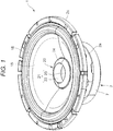
Fig. 1 is a perspective view illustrating a speaker of a first embodiment of the invention in a state in which a sound generation side faces upward. -
Fig. 2 is a longitudinal sectional view of the speaker of the first embodiment illustrated inFig. 1 . -
Fig. 3 is a partially enlarged cross-sectional view of a part ofFig. 2 . -
Fig. 4 is a partially exploded perspective view illustrating a part of a structure of the speaker of the first embodiment illustrated inFig. 1 and including a partial cross-section. -
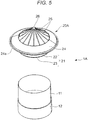
Fig. 5 is a partially exploded perspective view illustrating a part of a modified example of the speaker of the first embodiment of the invention. -
Fig. 6 is a partially cross-sectional view illustrating the speaker of the modified example illustrated inFig. 5 . -
Fig. 7 is a half cross-sectional view illustrating a part of a counter drive type speaker according to a second embodiment of the invention. - A
speaker 1 of a first embodiment of the invention illustrated inFigs. 1 to 4 includes aframe portion 2. For example, theframe portion 2 is formed by die-casting light metal or is formed by press forming a steel plate. As illustrated inFig. 2 , theframe portion 2 includes a magnetic circuitportion support portion 2a, adamper support portion 2b, and a vibrationplate support portion 2c. Theframe portion 2 may be integrally formed as a whole or may be formed such that one of the magnetic circuitportion support portion 2a, thedamper support portion 2b, and the vibrationplate support portion 2c is formed separately from the other parts and these parts are combined and fixed to each other. - A
magnetic circuit portion 3 is fixed to the magnetic circuitportion support portion 2a of theframe portion 2. As illustrated inFig. 2 , themagnetic circuit portion 3 includes apole yoke 4 which is located at the center, alower yoke 5 which is fixed to the lower side (the side of Z2) of thepole yoke 4, and anopposing yoke 6 which opposes the upside (the side of Z1) of thelower yoke 5 and amagnet 7 is fixed to be interposed between thelower yoke 5 and theopposing yoke 6. Themagnet 7 is an annular permanent magnet and thepole yoke 4 is located inside a center hole. The upper surface (the surface on the side of Z1) and the lower surface (the surface on the side of Z2) of themagnet 7 are magnetized to different magnetic poles. Then, a magnetic gap G is formed in an opposing portion between thepole yoke 4 and theopposing yoke 6. - The
speaker 1 is provided with abobbin 11. Thebobbin 11 is a cylindrical body of which a cross-section is a true circle and which is hollow. In addition, the cross-section of thebobbin 11 may be elliptical, oval, or polygonal. Thebobbin 11 is made of paper or a synthetic material of paper and synthetic resin. Alternatively, the bobbin is made of synthetic resin material. That is, thebobbin 11 is made of at least one of a paper material and a synthetic resin material and does not include a metal material. For that reason, thebobbin 11 can be decrease in weight. Thebobbin 11 has anopening end portion 11c formed at an end portion in the direction Z1. - As illustrated in
Figs. 2 and4 , avoice coil 12 is provided at the lower side (the side of Z2) of thebobbin 11. Thevoice coil 12 is formed by winding a coated wire on thebobbin 11. As illustrated inFig. 2 , a portion on which thevoice coil 12 is wound in thebobbin 11 is located inside the magnetic gap G of themagnetic circuit portion 3. - As illustrated in
Fig. 2 , avibration plate 15 is provided between thebobbin 11 and the vibrationplate support portion 2c of theframe portion 2. Thevibration plate 15 has a so-called cone shape and is made of, for example, paper or a synthetic material of paper and synthetic resin. Alternatively, thevibration plate 15 is made of a synthetic resin material. That is, thevibration plate 15 is made of at least one of a paper material and a synthetic resin material. - As illustrated in
Fig. 2 , an outerperipheral support member 18 is provided between the vibrationplate support portion 2c and an outerperipheral edge 15a of thevibration plate 15. The outerperipheral support member 18 has a circular cross-section and is deformable with the vibration of thevibration plate 15. As illustrated in the enlarged view ofFig. 3 , an innerperipheral edge 15b of thevibration plate 15 is fixed to anouter surface 11a of thebobbin 11 by adhering. In thevibration plate 15, the innerperipheral edge 15b at an intermediate portion away from theopening end portion 11c of thebobbin 11 in the direction Z2 is fixed to the outer surface of thebobbin 11 by adhering. In thebobbin 11, a portion to which thevibration plate 15 is fixed is a vibration plate fixed portion (i) and a portion in which the vibration plate fixed portion (i) exists is an intermediate portion away from theopening end portion 11c by a distance L1. - As illustrated in
Fig. 2 , adamper member 16 is provided between thebobbin 11 and thedamper support portion 2b of theframe portion 2.Fig. 3 is an enlarged cross-sectional view of thedamper member 16 andFig. 4 is a perspective view of a part of thedamper member 16. - The
damper member 16 is made of, for example, a woven fabric impregnated with resin or the like. Thedamper member 16 is corrugated and its cross-section is corrugated. As illustrated inFig. 2 , an outerperipheral edge 16a of thedamper member 16 is fixed to thedamper support portion 2b of theframe portion 2. As illustrated in the enlarged view ofFig. 3 , the innerperipheral edge 16b of thedamper member 16 is fixed to theouter surface 11a of thebobbin 11 by adhering. In thebobbin 11, a portion to which the innerperipheral edge 16b of thedamper member 16 is fixed by adhering is a damper member fixed portion (ii). - As illustrated in
Fig. 3 , the vibration plate fixed portion (i) and the damper member fixed portion (ii) of thebobbin 11 are very close to each other. When a portion of a distance L0 from the upper openingend portion 11c of thebobbin 11 to theupper end portion 12a of thevoice coil 12 is set as amain body 13 of thebobbin 11, the vibration plate fixed portion (i) and the damper member fixed portion (ii) are located at the intermediate portion of themain body 13. That is, a distance L1 from the openingend portion 11c of thebobbin 11 to the vibration plate fixed portion (i) is 1/3 or more and 2/3 or less of the length dimension L0 of themain body 13. Further, a distance L2 between the vibration plate fixed portion (i) and the damper member fixed portion (ii) in the vertical direction is 1/5 or less and preferably 1/10 or less of the distance L0. - As illustrated in
Figs. 2 and3 , acap member 20 is attached to thebobbin 11. Thecap member 20 is fitted into the hollow inner portion of thebobbin 11 from the openingend portion 11c of thebobbin 11. Thecap member 20 is formed by injection-molding synthetic resin and is integrally formed as a whole or is formed such that a plurality of parts which is formed by injection-molding synthetic resin is combined with each other. - As illustrated in the enlarged view of
Fig. 3 , thecap member 20 includes acylindrical portion 22 which extends downward toward the intermediate portion from the openingend portion 11c inside the hollow inner portion of thebobbin 11. Abottom surface portion 23 is provided at an end portion 22a (an end portion on the side of Z2) facing the inside of thebobbin 11 in thecylindrical portion 22. The end portion 22a of thecylindrical portion 22 is completely covered by thebottom surface portion 23 and is able to prevent dust or liquid from intruding into themagnetic circuit portion 3 from a space on the side of Z1. Here, an opening may be formed in a part of thebottom surface portion 23. In thecap member 20, abobbin reinforcement portion 21 is formed by thecylindrical portion 22 and thebottom surface portion 23. - The
cylindrical portion 22 contacts theinner surface 11b of thebobbin 11 or opposes theinner surface 11b through a narrow gap. The outer peripheral surface of thecylindrical portion 22 and theinner surface 11b of thebobbin 11 are fixed to each other by an adhesive in at least a part thereof. It is preferable that the outer peripheral surface of thecylindrical portion 22 and theinner surface 11b of thebobbin 11 are fixed to each other by an adhesive in an area covering at least the vibration plate fixed portion (i) and the damper member fixed portion (ii), for example, a height range of L3 illustrated inFig. 3 . Here, it is further preferable that theinner surface 11b and the outer surface of thecylindrical portion 22 adhere to each other in the entire area of the range of the height L4 in which thebobbin 11 and thecylindrical portion 22 face each other. - The height dimension L4 of the area in which the
inner surface 11b of thebobbin 11 and the outer peripheral surface of thecylindrical portion 22 oppose each other is preferably 2/5 or more and further preferably 1/2 or more of the height dimension L0 from the openingend portion 11c of thebobbin 11 to theupper end portion 12a of thevoice coil 12. When the height dimension is provided in the above-described range, thebobbin 11 can be effectively reinforced. - Further, the end portion 22a of the
cylindrical portion 22 is preferably located at the lower side (the side of Z2) in relation to the vibration plate fixed portion (i) and is further preferably located at the lower side (the side of Z2) in relation to both the vibration plate fixed portion (i) and the damper member fixed portion (ii). Here, when the height dimension L4 is 2/5 or more of the height dimension L0, the end portion 22a of thecylindrical portion 22 may be located at the slightly upper side (the side of Z1) in relation to the vibration plate fixed portion (i) and the damper member fixed portion (ii). That is, the end portion 22a of thecylindrical portion 22 may be located in the vicinity of at least the vibration plate fixed portion (i) and the damper member fixed portion (ii). - The
cap member 20 is provided with anouter support portion 24 which further extends to the outer peripheral side from the openingend portion 11c of thebobbin 11 and theperipheral edge portion 24a of theouter support portion 24 is fixed to a surface facing the side of Z1 in thevibration plate 15 by adhering. - In the
speaker 1 of the first embodiment, when a voice current flows to thevoice coil 12, an electromagnetic force (magnetic energy) caused by the voice current and the magnetic field traversing the magnetic gap G of themagnetic circuit portion 3 is converted into kinetic energy in the Z1-Z2 direction of thevoice coil 12. This kinetic energy is transmitted from thebobbin 11 to thevibration plate 15 so that thevibration plate 15 is vibrated and sound energy is emitted to a space. - As illustrated in
Fig. 3 , thebobbin 11 is reinforced by thebobbin reinforcement portion 21 of thecap member 20 in the range of the height L4 of preferably 2/5 or more in many parts of the height dimension L0 from the openingend portion 11c of thebobbin 11 to theupper end portion 12a of thevoice coil 12. For that reason, it is possible to improve the rigidity of thebobbin 11 that transmits the kinetic energy. Here, since thebobbin 11 is made of at least one of a paper material and a synthetic resin material, it is possible to reduce the mass of thebobbin 11. Since thebobbin 11 is lightweight and has high rigidity, thebobbin 11 can efficiently transmit the kinetic energy applied to thevoice coil 12 to thevibration plate 15 without attenuating or distorting the kinetic energy. As a result, it is possible to prevent a decrease in sound pressure and to easily maintain linearity of sound. - Further, since a resistance force is applied from the
vibration plate 15 and thedamper member 16 when thebobbin 11 moves in the Z1-Z2 direction, stress easily concentrates on the vibration plate fixed portion (i) and the damper member fixed portion (ii) of thebobbin 11. Particularly, since thevibration plate 15 has a large area and high rigidity, stress easily concentrates on the vibration plate fixed portion (i) in thebobbin 11. Here, as illustrated inFig. 3 , when thecylindrical portion 22 of thebobbin reinforcement portion 21 of thecap member 20 is fixed to theinner surface 11b of thebobbin 11 by adhering in an opposing state in the vibration plate fixed portion (i) and the damper member fixed portion (ii), it is possible to easily suppress deformation due to the concentration of stress in the vibration plate fixed portion (i) and the damper member fixed portion (ii). - Further, the
bobbin reinforcement portion 21 of thecap member 20 includes thebottom surface portion 23, but when thebottom surface portion 23 is disposed in the vicinity of the vibration plate fixed portion (i) and the damper member fixed portion (ii) of thebobbin 11, the rigidity of thebobbin 11 in the vibration plate fixed portion (i) and the damper member fixed portion (ii) can be improved. Accordingly, it is possible to suppress deformation in the bobbin crushing direction and to maintain high kinetic energy transmission efficiency due to thebobbin 11. - Further, the coil wire connected to the
voice coil 12 is laid from thebobbin 11 toward thevibration plate 15, but since the repeated bending of the coil wire is suppressed due to the reinforcement of thebobbin 11, a disconnection of the coil wire can be prevented. - Further, the
cap member 20 includes theouter support portion 24 and theperipheral edge portion 24a of theouter support portion 24 is fixed to thevibration plate 15 by adhering. Since thebobbin 11 can be reinforced by thecap member 20 and thevibration plate 15 can be also supported, it is possible to prevent distortion and unnecessary vibration in thebobbin 11, the inner peripheral portion of thevibration plate 15, and the like and to further easily attenuate a sound effect. -
Figs. 5 and6 illustrate a part of aspeaker 1A which is a modified example of the first embodiment of the invention. - In the
speaker 1A of the modified example illustrated inFigs. 5 and6 , acap member 20A is attached to the openingend portion 11c of thebobbin 11. Thecap member 20A includes thecylindrical portion 22 and thebottom surface portion 23 as thebobbin reinforcement portion 21 and includes theouter support portion 24 extending from the openingend portion 11c toward the outer peripheral side. Further, thecap member 20A includes asupport column 26 which is uprightly formed to the upper side (the side of Z1) from the center of thebottom surface portion 23 and a plurality offins 25 which extends in the Z1-Z2 direction is arranged regularly in the circumferential direction between thecylindrical portion 22 and thesupport column 26. - Since the
cap member 20A has high rigidity, the capability of reinforcing thebobbin 11 is further improved. -
Fig. 7 is a half cross-sectional view illustrating a part of a counterdrive type speaker 101 which is a second embodiment of the invention. - Similarly to the
speaker 1 of the first embodiment, in thespeaker 101 illustrated inFig. 7 , a direction in which an opening angle of a cone-shaped vibration plate is less than 180° is an upward direction and is directed in the Z1 direction. - In the counter
drive type speaker 101, themagnetic circuit portion 3 is provided at the upper side (the side of Z1) and themagnetic circuit portion 3 is supported by theframe portion 2. Themagnetic circuit portion 3 includes apole yoke 4, anupper yoke 5a, and two opposingyokes magnet 7 is fixed between thepole yoke 4 and the opposingyoke 6a and the magnetic gap G is formed in the opposing portion between the opposingyoke 6a and the opposingyoke 6a. - The
voice coil 12 is wound on thebobbin 11 at the upper side and thevoice coil 12 is located inside the magnetic gap G. - The inner
peripheral edge 15b of thevibration plate 15 is fixed to the outer surface of thebobbin 11 and the innerperipheral edges 16b of twodamper members 16 are also fixed to thebobbin 11. The outer peripheral edge of thevibration plate 15 and the outer peripheral edge of thedamper member 16 are fixed to theframe portion 2. - The
cap member 20 is attached to the opening end portion at the lower side (the side of Z2) of thebobbin 11. Thecap member 20 includes thecylindrical portion 22 and thebottom surface portion 23 as thebobbin reinforcement portion 21. Thecylindrical portion 22 opposes the inner surface of thebobbin 11 in the vibration plate fixed portion (i) and the damper member fixed portion (ii) and thebobbin 11 and thecylindrical portion 22 are fixed to each other by adhering in at least the vibration plate fixed portion (i) and the damper member fixed portion (ii). -
- 1, 1A, 101: speaker
- 2: frame portion
- 3: magnetic circuit portion
- 11: bobbin
- 11a: outer surface
- 11b: inner surface
- 11c: opening end portion
- 12: voice coil
- 12a: upper end portion
- 15: vibration plate
- 20, 20A: cap member
- 21: bobbin reinforcement portion
- 22: cylindrical portion
- 23: bottom surface portion
- 24: outer support portion
- G: magnetic gap
- (i): vibration plate fixed portion
- (ii): damper member fixed portion
Claims (6)
- A speaker (1) comprising:a magnetic circuit portion (3) supported by a frame portion (2) and forming a magnetic gap (G);a hollow bobbin (11);a voice coil (12) wound on the bobbin (11) and located inside the magnetic gap (G); anda vibration plate (15) disposed between the frame portion (2) and the bobbin (11), characterized in thatthe vibration plate (15) is fixed to a vibration plate fixed portion (i) located at an outer surface of an intermediate portion away from an opening end portion (11c) of the bobbin (11), a cap member (20) is attached to the opening end portion (11c) of the bobbin (11), and the cap member (20) is provided with a bobbin reinforcement portion (21) extending from the opening end portion (11c) toward the intermediate portion inside the bobbin (11) and opposing the vibration plate fixed portion (i) or opposing the vicinity of the vibration plate fixed portion (i).
- The speaker (1) according to claim 1, characterized in that the bobbin reinforcement portion (21) is fixed to the bobbin (11) in at least an inner surface of the vibration plate fixed portion (i).
- The speaker (1) according to claim 1 or 2, characterized in that the bobbin reinforcement portion (21) includes a cylindrical portion (22) opposing an inner surface of the bobbin (11) and a bottom surface portion (23) located at an end portion directed toward the inside of the bobbin (11) of the cylindrical portion (22) and the bottom surface portion (23) opposes the vibration plate fixed portion (i) or the vicinity thereof.
- The speaker (1) according to any one of claims 1 to 3, characterized in that the vibration plate fixed portion (i) is located at a position away from the opening end portion (11c) of the bobbin (11).
- The speaker (1) according to any one of claims 1 to 4, characterized in that the cap member (20) is provided with an outer support portion (24) extending toward an outer peripheral side in relation to the opening end portion of the bobbin (11) and the outer support portion (24) is fixed to the vibration plate (15).
- The speaker (1) according to any one of claims 1 to 5, characterized in that a damper member (16) is provided between the frame portion (2) and the bobbin (11) and the bobbin reinforcement portion (21) also opposes a fixed portion (ii) of the damper member (16) in the bobbin (11).
Applications Claiming Priority (1)
| Application Number | Priority Date | Filing Date | Title |
|---|---|---|---|
| JP2017109642A JP2018207265A (en) | 2017-06-02 | 2017-06-02 | Loudspeaker |
Publications (1)
| Publication Number | Publication Date |
|---|---|
| EP3410741A1 true EP3410741A1 (en) | 2018-12-05 |
Family
ID=62486484
Family Applications (1)
| Application Number | Title | Priority Date | Filing Date |
|---|---|---|---|
| EP18174877.3A Ceased EP3410741A1 (en) | 2017-06-02 | 2018-05-29 | Speaker |
Country Status (3)
| Country | Link |
|---|---|
| US (1) | US10506348B2 (en) |
| EP (1) | EP3410741A1 (en) |
| JP (1) | JP2018207265A (en) |
Cited By (1)
| Publication number | Priority date | Publication date | Assignee | Title |
|---|---|---|---|---|
| US12302077B2 (en) | 2019-11-08 | 2025-05-13 | B&W Group Ltd. | Loudspeaker spiders |
Families Citing this family (7)
| Publication number | Priority date | Publication date | Assignee | Title |
|---|---|---|---|---|
| WO2019102860A1 (en) * | 2017-11-24 | 2019-05-31 | ヤマハ株式会社 | Diaphragm and electroacoustic transducer comprising this diaphragm |
| WO2021003602A1 (en) * | 2019-07-05 | 2021-01-14 | 瑞声声学科技(深圳)有限公司 | Actuator |
| KR102888435B1 (en) * | 2020-09-21 | 2025-11-19 | 삼성전자주식회사 | Speaker apparatus and sound outputting apparatus comprising the same |
| CN213462265U (en) * | 2020-09-28 | 2021-06-15 | 瑞声科技(新加坡)有限公司 | Sound production device |
| JP1748252S (en) * | 2023-02-15 | 2023-07-07 | speaker | |
| JP1748251S (en) * | 2023-02-15 | 2023-07-07 | speaker | |
| JP1748250S (en) * | 2023-02-15 | 2023-07-07 | speaker |
Citations (6)
| Publication number | Priority date | Publication date | Assignee | Title |
|---|---|---|---|---|
| JPS559170U (en) * | 1978-07-03 | 1980-01-21 | ||
| JPS5751395U (en) * | 1980-09-09 | 1982-03-24 | ||
| JP2002271889A (en) * | 2001-03-08 | 2002-09-20 | Sony Corp | Speaker device |
| JP2002271892A (en) * | 2001-03-08 | 2002-09-20 | Sony Corp | Speaker system |
| JP2005252923A (en) | 2004-03-08 | 2005-09-15 | Matsushita Electric Ind Co Ltd | Speaker |
| US20070223775A1 (en) * | 2006-03-09 | 2007-09-27 | Pioneer Corporation | Voice coil bobbin and speaker system |
-
2017
- 2017-06-02 JP JP2017109642A patent/JP2018207265A/en active Pending
-
2018
- 2018-04-17 US US15/955,228 patent/US10506348B2/en active Active
- 2018-05-29 EP EP18174877.3A patent/EP3410741A1/en not_active Ceased
Patent Citations (6)
| Publication number | Priority date | Publication date | Assignee | Title |
|---|---|---|---|---|
| JPS559170U (en) * | 1978-07-03 | 1980-01-21 | ||
| JPS5751395U (en) * | 1980-09-09 | 1982-03-24 | ||
| JP2002271889A (en) * | 2001-03-08 | 2002-09-20 | Sony Corp | Speaker device |
| JP2002271892A (en) * | 2001-03-08 | 2002-09-20 | Sony Corp | Speaker system |
| JP2005252923A (en) | 2004-03-08 | 2005-09-15 | Matsushita Electric Ind Co Ltd | Speaker |
| US20070223775A1 (en) * | 2006-03-09 | 2007-09-27 | Pioneer Corporation | Voice coil bobbin and speaker system |
Cited By (1)
| Publication number | Priority date | Publication date | Assignee | Title |
|---|---|---|---|---|
| US12302077B2 (en) | 2019-11-08 | 2025-05-13 | B&W Group Ltd. | Loudspeaker spiders |
Also Published As
| Publication number | Publication date |
|---|---|
| US10506348B2 (en) | 2019-12-10 |
| JP2018207265A (en) | 2018-12-27 |
| US20180352336A1 (en) | 2018-12-06 |
Similar Documents
| Publication | Publication Date | Title |
|---|---|---|
| EP3410741A1 (en) | Speaker | |
| KR101690830B1 (en) | System for vibration confinement | |
| US9743192B2 (en) | Speaker and vibration control unit | |
| US9485582B2 (en) | Speaker | |
| US9479873B2 (en) | Speaker apparatus | |
| EP2852180A1 (en) | Speaker and edge structure for same | |
| US9538291B2 (en) | Speaker | |
| JP2009171352A (en) | Speaker unit | |
| EP3177036A1 (en) | Electroacoustic transducer | |
| JP4802307B2 (en) | Vibration actuator | |
| US10264347B2 (en) | Two-way speaker device having diaphragm of second speaker unit inside voice coil bobbin of first speaker unit | |
| US11395070B2 (en) | Diaphragm and electroacoustic transducer including the diaphragm | |
| KR101667679B1 (en) | Vibration module for slim speaker and high-powered slim speaker including the vibration module | |
| JP3219567U (en) | Voice coil diaphragm used for noise reduction | |
| US20200280806A1 (en) | Vibratable Element for Loudspeaker Use and Loudspeaker Device | |
| US11284198B2 (en) | Speaker unit | |
| US7587060B2 (en) | Speaker device | |
| JP4264579B2 (en) | Speaker device | |
| JP2017168979A (en) | Speaker and television apparatus | |
| JP2023018088A (en) | speaker device | |
| US20250056160A1 (en) | Motor assembly for speaker device | |
| US20060002579A1 (en) | Speaker device | |
| EP4021014A1 (en) | Acoustic device | |
| KR102146565B1 (en) | Speaker Having Frequency Controlling Structure | |
| JP2008103856A (en) | Speaker unit |
Legal Events
| Date | Code | Title | Description |
|---|---|---|---|
| PUAI | Public reference made under article 153(3) epc to a published international application that has entered the european phase |
Free format text: ORIGINAL CODE: 0009012 |
|
| STAA | Information on the status of an ep patent application or granted ep patent |
Free format text: STATUS: THE APPLICATION HAS BEEN PUBLISHED |
|
| AK | Designated contracting states |
Kind code of ref document: A1 Designated state(s): AL AT BE BG CH CY CZ DE DK EE ES FI FR GB GR HR HU IE IS IT LI LT LU LV MC MK MT NL NO PL PT RO RS SE SI SK SM TR |
|
| AX | Request for extension of the european patent |
Extension state: BA ME |
|
| STAA | Information on the status of an ep patent application or granted ep patent |
Free format text: STATUS: REQUEST FOR EXAMINATION WAS MADE |
|
| 17P | Request for examination filed |
Effective date: 20190508 |
|
| RBV | Designated contracting states (corrected) |
Designated state(s): AL AT BE BG CH CY CZ DE DK EE ES FI FR GB GR HR HU IE IS IT LI LT LU LV MC MK MT NL NO PL PT RO RS SE SI SK SM TR |
|
| STAA | Information on the status of an ep patent application or granted ep patent |
Free format text: STATUS: EXAMINATION IS IN PROGRESS |
|
| 17Q | First examination report despatched |
Effective date: 20190627 |
|
| STAA | Information on the status of an ep patent application or granted ep patent |
Free format text: STATUS: THE APPLICATION HAS BEEN REFUSED |
|
| 18R | Application refused |
Effective date: 20210428 |