EP3410424A1 - Emission driver and display device including the same - Google Patents
Emission driver and display device including the same Download PDFInfo
- Publication number
- EP3410424A1 EP3410424A1 EP18183563.8A EP18183563A EP3410424A1 EP 3410424 A1 EP3410424 A1 EP 3410424A1 EP 18183563 A EP18183563 A EP 18183563A EP 3410424 A1 EP3410424 A1 EP 3410424A1
- Authority
- EP
- European Patent Office
- Prior art keywords
- signal
- node
- pull
- driving
- emission
- Prior art date
- Legal status (The legal status is an assumption and is not a legal conclusion. Google has not performed a legal analysis and makes no representation as to the accuracy of the status listed.)
- Granted
Links
Images


Classifications
-
- G—PHYSICS
- G11—INFORMATION STORAGE
- G11C—STATIC STORES
- G11C19/00—Digital stores in which the information is moved stepwise, e.g. shift registers
- G11C19/28—Digital stores in which the information is moved stepwise, e.g. shift registers using semiconductor elements
-
- G—PHYSICS
- G09—EDUCATION; CRYPTOGRAPHY; DISPLAY; ADVERTISING; SEALS
- G09G—ARRANGEMENTS OR CIRCUITS FOR CONTROL OF INDICATING DEVICES USING STATIC MEANS TO PRESENT VARIABLE INFORMATION
- G09G3/00—Control arrangements or circuits, of interest only in connection with visual indicators other than cathode-ray tubes
- G09G3/20—Control arrangements or circuits, of interest only in connection with visual indicators other than cathode-ray tubes for presentation of an assembly of a number of characters, e.g. a page, by composing the assembly by combination of individual elements arranged in a matrix no fixed position being assigned to or needed to be assigned to the individual characters or partial characters
- G09G3/22—Control arrangements or circuits, of interest only in connection with visual indicators other than cathode-ray tubes for presentation of an assembly of a number of characters, e.g. a page, by composing the assembly by combination of individual elements arranged in a matrix no fixed position being assigned to or needed to be assigned to the individual characters or partial characters using controlled light sources
- G09G3/30—Control arrangements or circuits, of interest only in connection with visual indicators other than cathode-ray tubes for presentation of an assembly of a number of characters, e.g. a page, by composing the assembly by combination of individual elements arranged in a matrix no fixed position being assigned to or needed to be assigned to the individual characters or partial characters using controlled light sources using electroluminescent panels
- G09G3/32—Control arrangements or circuits, of interest only in connection with visual indicators other than cathode-ray tubes for presentation of an assembly of a number of characters, e.g. a page, by composing the assembly by combination of individual elements arranged in a matrix no fixed position being assigned to or needed to be assigned to the individual characters or partial characters using controlled light sources using electroluminescent panels semiconductive, e.g. using light-emitting diodes [LED]
- G09G3/3208—Control arrangements or circuits, of interest only in connection with visual indicators other than cathode-ray tubes for presentation of an assembly of a number of characters, e.g. a page, by composing the assembly by combination of individual elements arranged in a matrix no fixed position being assigned to or needed to be assigned to the individual characters or partial characters using controlled light sources using electroluminescent panels semiconductive, e.g. using light-emitting diodes [LED] organic, e.g. using organic light-emitting diodes [OLED]
- G09G3/3266—Details of drivers for scan electrodes
-
- G—PHYSICS
- G09—EDUCATION; CRYPTOGRAPHY; DISPLAY; ADVERTISING; SEALS
- G09G—ARRANGEMENTS OR CIRCUITS FOR CONTROL OF INDICATING DEVICES USING STATIC MEANS TO PRESENT VARIABLE INFORMATION
- G09G2230/00—Details of flat display driving waveforms
-
- G—PHYSICS
- G09—EDUCATION; CRYPTOGRAPHY; DISPLAY; ADVERTISING; SEALS
- G09G—ARRANGEMENTS OR CIRCUITS FOR CONTROL OF INDICATING DEVICES USING STATIC MEANS TO PRESENT VARIABLE INFORMATION
- G09G2300/00—Aspects of the constitution of display devices
- G09G2300/08—Active matrix structure, i.e. with use of active elements, inclusive of non-linear two terminal elements, in the pixels together with light emitting or modulating elements
- G09G2300/0809—Several active elements per pixel in active matrix panels
- G09G2300/0842—Several active elements per pixel in active matrix panels forming a memory circuit, e.g. a dynamic memory with one capacitor
- G09G2300/0861—Several active elements per pixel in active matrix panels forming a memory circuit, e.g. a dynamic memory with one capacitor with additional control of the display period without amending the charge stored in a pixel memory, e.g. by means of additional select electrodes
-
- G—PHYSICS
- G09—EDUCATION; CRYPTOGRAPHY; DISPLAY; ADVERTISING; SEALS
- G09G—ARRANGEMENTS OR CIRCUITS FOR CONTROL OF INDICATING DEVICES USING STATIC MEANS TO PRESENT VARIABLE INFORMATION
- G09G2310/00—Command of the display device
- G09G2310/02—Addressing, scanning or driving the display screen or processing steps related thereto
- G09G2310/0202—Addressing of scan or signal lines
- G09G2310/0205—Simultaneous scanning of several lines in flat panels
-
- G—PHYSICS
- G09—EDUCATION; CRYPTOGRAPHY; DISPLAY; ADVERTISING; SEALS
- G09G—ARRANGEMENTS OR CIRCUITS FOR CONTROL OF INDICATING DEVICES USING STATIC MEANS TO PRESENT VARIABLE INFORMATION
- G09G2310/00—Command of the display device
- G09G2310/02—Addressing, scanning or driving the display screen or processing steps related thereto
- G09G2310/0264—Details of driving circuits
- G09G2310/0286—Details of a shift registers arranged for use in a driving circuit
Definitions
- the invention generally relates to emission drivers and display devices including the same.
- Display devices can be driven by an analog driving method for enhanced image quality.
- a typical flat panel display includes a scan driver, a data driver, and an emission driver for driving the display panel.
- the emission driver controls light emission of the display panel.
- Typical emission drivers cannot generate a proper emission control signal corresponding to a change of a display mode (e.g., a sequential emission mode, simultaneous emission mode, etc.). In addition, it is difficult to control a duty rate of the emission control signal due to driver circuit configuration.
- an emission driver according to Claim 1. Details of embodiments are provided in the dependent claims.
- the present disclosure describes various aspects that are of interest in the context of the invention, and which may be referred to as embodiments even though they are not comprised in the scope of the claims, or describe only some of the features required for the invention.
- the present invention is defined solely by the scope of the claims.
- the invention sets-out to solve the above-mentioned problems of the art and provides an emission driver applied to a sequential emission mode and a simultaneous emission mode.
- the invention also seeks to provide a display device including the emission driver.
- a display device that includes a plurality of stages configured to output respective emission control signals.
- Each of the stages can include a first driving block configured to receive a first input signal, a first clock signal, a second clock signal, and a first driving signal, and to output a first intermediate signal in response to the first input signal and the first driving signal, a second driving block configured to receive a second input signal, the first clock signal, the second clock signal, and a second driving signal, and to output a second intermediate signal in response to the second input signal and the second driving signal, and a buffer block configured to receive the first intermediate signal and the second intermediate signal, and to output an emission control signal in response to the first intermediate signal and the second intermediate signal.
- the buffer block can selectively output the emission control signal to operate in a sequential emission mode or in a simultaneous emission mode, the emission control signal being sequentially output from the each of the stages in the sequential emission mode, the emission control signal being simultaneously output from the each of the stages in the simultaneous emission mode.
- the buffer block can determine a duration in which the emission control signal has a first voltage level based on an interval between a time point at which the first intermediate signal has a low voltage level and a time point at which the second intermediate signal has the low voltage level.
- the buffer block outputs the emission control signal having the first voltage level when the first intermediate signal has the low voltage level, and outputs the emission control signal having a second voltage level lower than the first voltage level when the second intermediate signal has the low voltage level.
- a rising edge of the emission control signal is synchronized with a falling edge of the first intermediate signal, and a falling edge of the emission control signal can be s synchronized with a falling edge of the second intermediate signal.
- the first driving signal and the second driving signal is maintained to have a high voltage level when the emission driver operates in the sequential emission mode.
- the first input signal, the second input signal, the first clock signal, and the second clock signal can be maintained to have the high voltage level when the emission driver operates in the simultaneous emission mode.
- the first driving block includes a first input unit configured to transmit the first clock signal to a second node in response to a first node signal applied to a first node, a second input unit configured to transmit the first input signal to the first node in response to the first clock signal, a pull-up unit configured to pull up the first intermediate signal in response to a second node signal applied to the second node, a pull-down unit configured to pull down the first intermediate signal in response to the first node signal, a simultaneous driving control unit configured to inactivate the pull-down unit in response to the first driving signal, a holding unit configured to maintain the second node signal in response to the first clock signal, and a stabilizing unit configured to stabilize the first intermediate signal in response to the second node signal and the second clock signal.
- the first input unit includes a first transistor having a gate electrode connected to the first node, a source electrode to which the first clock signal is applied, and a drain electrode connected to the second node.
- the second input unit can include a second transistor having a gate electrode to which the first clock signal is applied, a source electrode to which the first input signal is applied, and a drain electrode connected to the first node.
- the pull-up unit can include a third transistor having a gate electrode connected to the second node, a source electrode to which the first driving signal is applied, and a drain electrode connected to an output terminal for outputting the first intermediate signal.
- the pull-down unit can include a fourth transistor having a gate electrode connected to the first node, a source electrode to which the second clock signal is applied, and a drain electrode connected to the output terminal.
- the driving control unit can include a fifth transistor having a gate electrode to which the first driving signal is applied, a source electrode to which a high DC voltage is applied, and a drain electrode connected to the first node.
- the holding unit can include a sixth transistor having a gate electrode and a source electrode to which the first clock is applied, and a drain electrode connected to the second node.
- the stabilizing unit includes a seventh transistor and an eighth transistor that are connected in series.
- the seventh transistor can include a gate electrode connected to the second node, a source electrode to which a pull-up voltage of the first intermediate signal is applied, and a drain electrode connected to a source electrode of the eighth transistor.
- the eighth transistor can include a gate electrode to which the second clock signal is applied, a source electrode connected to the drain electrode of the seventh transistor, and a drain electrode connected to the first node.
- the second driving block includes a first input unit configured to transmit the second clock signal to a second node in response to a first node signal applied to a first node, a second input unit configured to transmit the second input signal to the first node in response to the second clock signal, a pull-up unit configured to pull up the second intermediate signal in response to a second node signal applied to the second node, a pull-down unit configured to pull down the second intermediate signal in response to the first node signal, a driving control unit configured to inactivate the pull-down unit in response to the second driving signal, a holding unit configured to maintain the second node signal in response to the second clock signal, and a stabilizing unit configured to stabilize the second intermediate signal in response to the second node signal and the first clock signal.
- the first input unit includes a first transistor having a gate electrode connected to the first node, a source electrode to which the second clock signal is applied, and a drain electrode connected to the second node.
- the second input unit can include a second transistor having a gate electrode to which the second clock signal is applied, a source electrode to which the second input signal is applied, and a drain electrode connected to the first node.
- the pull-up unit can include a third transistor having a gate electrode connected to the second node, a source electrode to which the second driving signal is applied, and a drain electrode connected to an output terminal for outputting the second intermediate signal.
- the pull-down unit can include a fourth transistor having a gate electrode connected to the first node, a source electrode to which the first clock signal is applied, and a drain electrode connected to the output terminal.
- the driving control unit can include a fifth transistor having a gate electrode to which the second driving signal, a source electrode to which a high DC voltage is applied, and a drain electrode connected to the first node.
- the holding unit can include a sixth transistor having a gate electrode and a source electrode to which the second clock is applied, and a drain electrode connected to the second node.
- the buffer block includes a first input unit configured to transmit a high DC voltage to a first node in response to the first intermediate signal and to transmit a low DC voltage to a second node in response to the first intermediate signal, a second input unit configured to transmit the low DC voltage to the first node in response to the second intermediate signal, a first holding unit configured to maintain a second node signal applied to the second node in response to a first node signal applied to the first node, a pull-up unit configured to pull up the emission control signal in response to the second node signal, and a pull-down unit configured to pull down the emission control signal in response to the first node signal.
- the first input unit includes a first transistor having a gate electrode to which the first intermediate signal is applied, a source electrode to which the high DC voltage is applied, and a drain electrode connected to the first node, and a second transistor having a gate electrode to which the first intermediate signal is applied, a source electrode to which the low DC voltage is applied, and a drain electrode connected to the second node.
- the second input unit includes a third transistor having a gate electrode to which the second intermediate signal is applied, a source electrode to which the low DC voltage is applied, and a drain electrode connected to the first node.
- the first holding unit can include a fourth transistor having a gate electrode connected to the first node, a source electrode to which the high DC voltage is applied, and a drain electrode connected to the second node.
- the pull-up unit can include a fifth transistor having a gate electrode connected to the second node, a source electrode to which the high DC voltage is applied, and a drain electrode connected to an emission control signal output terminal for outputting the emission control signal.
- the pull-down unit can include a sixth transistor having a gate electrode connected to the first node, a source electrode to which the low DC voltage is applied, and a drain electrode connected to the emission control signal output terminal.
- the pull-down unit includes a first pull-down transistor and a second pull-down transistor that are connected in series.
- the first pull-down transistor can include a gate electrode connected to the first node, a source electrode connected to a drain electrode of the second pull-down transistor, and a drain electrode connected to an emission control signal output terminal.
- the second pull-down transistor can include a gate electrode to which a third clock signal is applied, a source electrode connected to the gate electrode, and the drain electrode connected to the source electrode of the first pull-down transistor.
- the second input unit includes a third transistor having a gate electrode to which the second intermediate signal is applied, a source electrode to which the low DC voltage is applied, and a drain electrode connected to the first node.
- the first holding unit can include a fourth transistor having a gate electrode connected to the first node, a source electrode to which the high DC voltage is applied, and a drain electrode connected to the second node.
- the pull-up unit can include a fifth transistor having a gate electrode connected to the second node, a source electrode to which the high DC voltage is applied, and a drain electrode connected to the emission control signal output terminal.
- the buffer block further includes a second holding unit configured to maintain the first node signal in response to the second node signal.
- the second holding unit can include a holding transistor having a gate electrode connected to the second node, a source electrode to which the high DC voltage is applied, and a drain electrode connected to the first node.
- Another aspect of the invention provides a method of manufacturing a display device that includes a display panel including a plurality of pixels, a data driver configured to output a plurality of data signals to the display panel, a scan driver including a plurality of scan stages, each of the scan stages outputting a scan signal to the display panel, and an emission driver including a plurality of stages, each of the stages outputting an emission control signal to the display panel.
- Each of the stages of the emission driver can include a first driving block configured to receive a first input signal, a first clock signal, a second clock signal, and a first driving signal, and to output a first intermediate signal in response to the first input signal and the first driving signal, a second driving block configured to receive a second input signal, the first clock signal, the second clock signal, and a second driving signal, and to output a second intermediate signal in response to the second input signal and the second driving signal, and a buffer block configured to receive the first intermediate signal and the second intermediate signal, and to output the emission control signal in response to the first intermediate signal and the second intermediate signal.
- the buffer block can selectively output the emission control signal to operate in a sequential emission mode or in a simultaneous emission mode, the emission control signal being sequentially output from the each of the stages in the sequential emission mode, and the emission control signal being simultaneously output from the each of the stages in the simultaneous emission mode.
- the buffer block can determine a duration in which the emission control signal has a first voltage level based on an interval between a time point at which the first intermediate signal has the low voltage level and a time point at which the second intermediate signal has the low voltage level.
- the buffer block outputs the emission control signal having the first voltage level when the first intermediate signal has the low voltage level, and output the emission control signal having a second voltage level lower than the first voltage level when the second intermediate signal has the low voltage level.
- the first driving signal and the second driving signal are maintained to have a high voltage level when the emission driver operates in the sequential emission mode.
- the first input signal, the second input signal, the first clock signal, and the second clock signal can be maintained to have the high voltage level when the emission driver operates in the simultaneous emission mode.
- the first driving block includes a first input unit configured to transmit the first clock signal to a second node in response to a first node signal applied to a first node, a second input unit configured to transmit the first input signal to the first node in response to the first clock signal, a pull-up unit configured to pull up the first intermediate signal in response to a second node signal applied to the second node, a pull-down unit configured to pull down the first intermediate signal in response to the first node signal, a driving control unit configured to inactivate the pull-down unit in response to the first driving signal, a holding unit configured to maintain the second node signal in response to the first clock signal, and a stabilizing unit configured to stabilize the first intermediate signal in response to the second node signal and the second clock signal.
- the buffer block includes a first input unit configured to transmit a high DC voltage to a first node in response to the first intermediate signal and to transmit a low DC voltage to a second node in response to the first intermediate signal, a second input unit configured to transmit the low DC voltage to the first node in response to the second intermediate signal, a holding unit configured to maintain a second node signal applied to the second node in response to a first node signal applied to the first node, a pull-up unit configured to pull up the emission control signal in response to the second node signal, and a pull-down unit configured to pull down the emission control signal in response to the first node signal.
- the emission driver and the display device having the same can output the emission signal selectively and variously to operate in the respective emission modes (i.e., the sequential emission mode and the simultaneous emission mode) based on timing of the clock signals and the driving signals.
- driving the display device in various display modes e.g., 3-dimensional (3D) stereoscopic image display mode, etc.
- image quality can be improved.
- a falling speed of the emission control signal i.e., a pull down speed or response speed
- a circuit configuration of the buffer block i.e., a circuit configuration of the buffer block.
- a duty ratio can be freely controlled by adjusting the timing of the driving signals (in the simultaneous emission mode) or the timing of the input signals (in the sequential emission mode).
- an emission driver for a display device, the emission driver comprising a plurality of stages each configured to output an emission control signal.
- Each of the stages includes a first driving block configured to i) receive a first input signal, first and second clock signals, and a first driving signal, and ii) output a first intermediate signal based at least in part on the first input signal and the first driving signal.
- Each stage also includes a second driving block configured to i) receive a second input signal, the first and second clock signals, and a second driving signal, and ii) output a second intermediate signal based at least in part on the second input signal and the second driving signal.
- Each stage further includes a buffer block configured to i) receive the first and second intermediate signals, and ii) output an emission control signal based at least in part on the first and second intermediate signals, wherein the buffer block is further configured to selectively output the emission control signal so as to operate in a sequential emission mode or in a simultaneous emission mode.
- the stages are configured to i) sequentially output a plurality of the emission control signals in the sequential emission mode and ii) substantially simultaneously output the emission control signals in the simultaneous emission mode.
- the buffer block is further configured to determine a duration in which the emission control signal has a first voltage level based at least in part on an interval between a time point when the first intermediate signal has a low voltage level and a time point when the second intermediate signal has the low voltage level.
- the buffer block is further configured to output i) the emission control signal having the first voltage level when the first intermediate signal has the low voltage level and ii) the emission control signal having a second voltage level lower than the first voltage level when the second intermediate signal has the low voltage level.
- a rising edge of the emission control signal is substantially synchronized with a falling edge of the first intermediate signal, wherein a falling edge of the emission control signal is substantially synchronized with a falling edge of the second intermediate signal.
- the first and second driving signals are configured to be maintained to have a high voltage level when the emission driver operates in the sequential emission mode, wherein the first and second input signals and the first and second clock signals are configured to be maintained to have the high voltage level when the emission driver operates in the simultaneous emission mode.
- the first driving block includes a first input unit configured to transmit the first clock signal to a second node based at least in part on a first node signal configured to be applied to a first node, a second input unit configured to transmit the first input signal to the first node based at least in part on the first clock signal, and a pull-up unit configured to pull up the first intermediate signal based at least in part on a second node signal configured to be applied to the second node.
- the first driving block further includes a pull-down unit configured to pull down the first intermediate signal based at least in part on the first node signal, a driving controller configured to inactivate the pull-down unit based at least in part on the first driving signal, a holding unit configured to maintain the second node signal based at least in part on the first clock signal, and a stabilizing unit configured to stabilize the first intermediate signal based at least in part on the second node signal and the second clock signal.
- the first input unit includes a first transistor having a gate electrode electrically connected to the first node, a source electrode to which the first clock signal is configured to be applied, and a drain electrode electrically connected to the second node.
- the second input unit includes a second transistor having a gate electrode to which the first clock signal is configured to be applied, a source electrode to which the first input signal is configured to be applied, and a drain electrode electrically connected to the first node.
- the pull-up unit includes a third transistor having a gate electrode electrically connected to the second node, a source electrode to which the first driving signal is configured to be applied, and a drain electrode electrically connected to an output terminal configured to output the first intermediate signal.
- the pull-down unit includes a fourth transistor having a gate electrode electrically connected to the first node, a source electrode to which the second clock signal is configured to be applied, and a drain electrode electrically connected to the output terminal.
- the driving controller includes a fifth transistor having a gate electrode to which the first driving signal is configured to be applied, a source electrode to which a high DC voltage is configured to be applied, and a drain electrode electrically connected to the first node.
- the holding unit includes a sixth transistor having a gate electrode and a source electrode to which the first clock is configured to be applied, and a drain electrode electrically connected to the second node.
- the stabilizing unit includes seventh and eighth transistors electrically connected in series.
- the seventh transistor includes a gate electrode electrically connected to the second node, a source electrode to which a pull-up voltage of the first intermediate signal is configured to be applied, and a drain electrode electrically connected to a source electrode of the eighth transistor.
- the eighth transistor includes a gate electrode to which the second clock signal is configured to be applied, a source electrode electrically connected to the drain electrode of the seventh transistor, and a drain electrode electrically connected to the first node.
- the second driving block includes a first input unit configured to transmit the second clock signal to a second node based at least in part on a first node signal configured to be applied to a first node, a second input unit configured to transmit the second input signal to the first node based at least in part on the second clock signal, and a pull-up unit configured to pull up the second intermediate signal based at least in part on a second node signal configured to be applied to the second node.
- the second driving block also includes a pull-down unit configured to pull down the second intermediate signal based at least in part on the first node signal, a driving controller configured to inactivate the pull-down unit based at least in part on the second driving signal.
- the second driving block further includes a holding unit configured to maintain the second node signal based at least in part on the second clock signal, and a stabilizing unit configured to stabilize the second intermediate signal based at least in part on the second node signal and the first clock signal.
- the first input unit includes a first transistor having a gate electrode electrically connected to the first node, a source electrode to which the second clock signal is configured to be applied, and a drain electrode electrically connected to the second node.
- the second input unit includes a second transistor having a gate electrode to which the second clock signal is configured to be applied, a source electrode to which the second input signal is configured to be applied, and a drain electrode electrically connected to the first node.
- the pull-up unit includes a third transistor having a gate electrode electrically connected to the second node, a source electrode to which the second driving signal is configured to be applied, and a drain electrode electrically connected to an output terminal configured to output the second intermediate signal.
- the pull-down unit includes a fourth transistor having a gate electrode electrically connected to the first node, a source electrode to which the first clock signal is configured to be applied, and a drain electrode electrically connected to the output terminal.
- the driving controller includes a fifth transistor having a gate electrode to which the second driving signal is configured to be applied, a source electrode to which a high DC voltage is configured to be applied, and a drain electrode electrically connected to the first node.
- the holding unit includes a sixth transistor having a gate electrode and a source electrode to which the second clock is configured to be applied, and a drain electrode electrically connected to the second node.
- the buffer block includes a first input unit configured to transmit i) a high DC voltage to a first node based at least in part on the first intermediate signal and ii) a low DC voltage to a second node based at least in part on the first intermediate signal.
- the buffer block also includes a second input unit configured to transmit the low DC voltage to the first node based at least in part on the second intermediate signal and a first holding unit configured to maintain a second node signal configured to be applied to the second node based at least in part on a first node signal configured to be applied to the first node.
- the buffer block further includes a pull-up unit configured to pull up the emission control signal based at least in part on the second node signal and a pull-down unit configured to pull down the emission control signal based at least in part on the first node signal.
- the first input unit includes a first transistor having a gate electrode to which the first intermediate signal is configured to be applied, a source electrode to which the high DC voltage is configured to be applied, and a drain electrode electrically connected to the first node.
- the first input unit also includes a second transistor having a gate electrode to which the first intermediate signal is configured to be applied, a source electrode to which the low DC voltage is configured to be applied, and a drain electrode electrically connected to the second node.
- the second input unit includes a third transistor having a gate electrode to which the second intermediate signal is configured to be applied, a source electrode to which the low DC voltage is configured to be applied, and a drain electrode electrically connected to the first node.
- the first holding unit includes a fourth transistor having a gate electrode electrically connected to the first node, a source electrode to which the high DC voltage is configured to be applied, and a drain electrode electrically connected to the second node.
- the pull-up unit includes a fifth transistor having a gate electrode electrically connected to the second node, a source electrode to which the high DC voltage is configured to be applied, and a drain electrode electrically connected to an emission control signal output terminal configured to output the emission control signal.
- the pull-down unit includes a sixth transistor having a gate electrode electrically connected to the first node, a source electrode to which the low DC voltage is configured to be applied, and a drain electrode electrically connected to the emission control signal output terminal.
- the pull-down unit includes first and second pull-down transistors electrically connected in series.
- the first pull-down transistor includes a gate electrode electrically connected to the first node, a source electrode electrically connected to a drain electrode of the second pull-down transistor, and a drain electrode electrically connected to an emission control signal output terminal.
- the second pull-down transistor includes a gate electrode to which a third clock signal is configured to be applied, a source electrode electrically connected to the gate electrode, and the drain electrode electrically connected to the source electrode of the first pull-down transistor.
- the second input unit includes a third transistor having a gate electrode to which the second intermediate signal is configured to be applied, a source electrode to which the low DC voltage is configured to be applied, and a drain electrode electrically connected to the first node.
- the first holding unit includes a fourth transistor having a gate electrode connected to the first node, a source electrode to which the high DC voltage is applied, and a drain electrode connected to the second node.
- the pull-up unit includes a fifth transistor having a gate electrode electrically connected to the second node, a source electrode to which the high DC voltage is configured to be applied, and a drain electrode electrically connected to the emission control signal output terminal.
- the buffer block further includes a second holding unit configured to maintain the first node signal based at least in part on the second node signal, wherein the second holding unit includes a holding transistor having a gate electrode electrically connected to the second node, a source electrode to which the high DC voltage is configured to be applied, and a drain electrode electrically connected to the first node.
- the second holding unit includes a holding transistor having a gate electrode electrically connected to the second node, a source electrode to which the high DC voltage is configured to be applied, and a drain electrode electrically connected to the first node.
- a display device comprising a display panel including a plurality of pixels, a data driver configured to output a plurality of data signals to the display panel, a scan driver including a plurality of scan stages each configured to output a scan signal to the display panel, and an emission driver including a plurality of stages each configured to output an emission control signal to the display panel.
- Each of the stages of the emission driver includes a first driving block configured i) to receive a first input signal, first and second clock signals, and a first driving signal, and ii) output a first intermediate signal based at least in part on the first input signal and the first driving signal.
- Each stage also includes a second driving block configured to i) receive a second input signal, the first and second clock signals, and a second driving signal, and ii) output a second intermediate signal based at least in part on the second input signal and the second driving signal.
- Each stage further includes a buffer block configured to i) receive the first and second intermediate signals, and ii) output the emission control signal based at least in part on the first and second intermediate signals.
- the buffer block is further configured to selectively output the emission control signal so as to operate in a sequential emission mode or in a simultaneous emission mode, wherein the stages of the emission driver are configured to i) sequentially output a plurality of the emission control signals in the sequential emission mode and ii) substantially simultaneously output the emission control signals in the simultaneous emission mode.
- the buffer block is further configured to determine a duration in which the emission control signal has a first voltage level based at least in part on an interval between a time point when the first intermediate signal has the low voltage level and a time point when the second intermediate signal has the
- the buffer block is further configured to output i) the emission control signal having the first voltage level when the first intermediate signal has the low voltage level and ii) the emission control signal having a second voltage level lower than the first voltage level when the second intermediate signal has the low voltage level.
- the first and second driving signals are configured to be maintained to have a high voltage level when the emission driver operates in the sequential emission mode, wherein the first and second input signals and the first and second clock signals are configured to be maintained to have the high voltage level when the emission driver operates in the simultaneous emission mode.
- the first driving block includes a first input unit configured to transmit the first clock signal to a second node based at least in part on a first node signal configured to be applied to a first node, a second input unit configured to transmit the first input signal to the first node based at least in part on the first clock signal, and a pull-up unit configured to pull up the first intermediate signal based at least in part on a second node signal configured to be applied to the second node.
- the first driving block also includes a pull-down unit configured to pull down the first intermediate signal based at least in part on the first node signal and a driving controller configured to inactivate the pull-down unit based at least in part on the first driving signal.
- the first driving block further includes a holding unit configured to maintain the second node signal based at least in part on the first clock signal and a stabilizing unit configured to stabilize the first intermediate signal based at least in part on the second node signal and the second clock signal.
- the buffer block includes a first input unit configured to transmit i) a high DC voltage to a first node based at least in part on the first intermediate signal and ii) a low DC voltage to a second node based at least in part on the first intermediate signal.
- the buffer block also includes a second input unit configured to transmit the low DC voltage to the first node based at least in part on the second intermediate signal.
- the buffer block further includes a holding unit configured to maintain a second node signal configured to be applied to the second node based at least in part on a first node signal configured to be applied to the first node, a pull-up unit configured to pull up the emission control signal based at least in part on the second node signal, and a pull-down unit configured to pull down the emission control signal based at least in part on the first node signal.
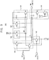
- FIG. 1 is block diagram of an emission driver according to example embodiments of the invention.
- the emission driver 100 includes a plurality of stages ST1, ST2, ST3, ST4, ... connected to one another.
- the stages ST1, ST2, ST3, ST4, ... can output emission control signals.
- Each of the stages ST1, ST2, ST3, ST4, ... can include a first clock terminal CK1, a second clock terminal CK2, a first driving signal input terminal GK1, a second driving signal input terminal GK2, a first input terminal INU, a second input terminal IND, and an emission control signal output terminal EM.
- Each of the stages ST1, ST2, ST3, ST4, ... can further include a high DC voltage input terminal VGH and a low DC voltage input terminal VGL.
- first and second clock signals CLK1 and CLK2 having different timings are respectively applied to the first and second clock terminals CK1 and CK2.
- the second clock signal CLK2 is a signal inverted from the first clock signal CLK1.
- the first clock signal CLK1 and the second clock signal CLK2 can be applied to the clock terminals in opposite sequences.
- the first clock signal CLK1 is applied to the first clock terminal CK1 of odd-numbered stages ST1, ST3, ... and the second clock signal CLK2 is applied to the second clock terminal CK2 of the odd-numbered stages ST1, ST3, ....
- the first clock signal CLK1 can be applied to the second clock terminal CK2 of even-numbered stages ST2, ST4, ...
- the second clock signal CLK2 can be applied to the first clock terminal CK1 of the even-numbered stages ST1, ST3, ....
- the first and second driving signals GCK1 and GCK2 can be respectively applied to the first and second driving signal input terminals GK1 and GK2.
- the first and second driving signals GCK1 and GCK2 can have a first voltage level (i.e., a low voltage level) within a certain duration when the emission driver 100 is driven by a simultaneous emission mode. All stages ST1, ST2, ST3, ST4, ... can output the same emission control signals EM[1], EM[2], EM[3], EM[4], ... substantially simultaneously.
- the first and second driving signals GCK1 and GCK2 can have a second voltage level (i.e., a high voltage level) when the emission driver 100 is driven by a sequential emission mode.
- the emission driver 100 can sequentially output the emission control signals EM[1], EM[2], EM[3], EM[4], ....
- the first and second driving signals GCK1 and GCK2 can be applied to the first and second driving signal input terminals GK1 and GK2 of the stages ST1, ST2, ST3, ST4, ....
- a first start signal IN1 or a first intermediate signal of a previous stage can be applied to the first input terminal INU.
- a second start signal IN2 or a second intermediate signal of the previous stage can be applied to the second input terminal IND.
- a first intermediate signal output terminal UP and a second intermediate signal output terminal DN can respectively output the first intermediate signal and the second intermediate signal.
- each first intermediate signal pulls up the emission control signals EM[1], EM[2], EM[3], EM[4], ... and each second intermediate signal pulls down the emission control signals EM[1], EM[2], EM[3], EM[4], ....
- the emission control signal output terminals EM can output the emission control signals EM[1], EM[2], EM[3], EM[4], ... to emission control lines.
- the emission control signals EM[1], EM[2], EM[3], EM[4], ... are sequentially outputted based at least in part on the first and second clock signals CLK1 and CLK2.
- the emission control signals EM[1], EM[2], EM[3], EM[4], ... can be substantially simultaneously outputted based at least in part on the first level of the first and second driving signals GCK1 and GCK2.
- FIG. 2 is a block diagram illustrating an example of a first stage of the emission driver of FIG. 1 .
- the first stage ST1 includes a first driving block 120, a second driving block 140 and a buffer block 160.
- the first driving block 120 can receive a first input signal IN1, a first clock signal CLK1, a second clock signal CLK2, and a first driving signal GCK1.
- the first driving block 120 can output a first intermediate signal OUT1 based at least in part on the first input signal IN1 and the first driving signal GCK1.
- the first intermediate signal OUT1 can be substantially simultaneously applied to a first input terminal UP of a first driving block of a second stage ST2 and the buffer block 160 of the first stage ST1.
- the second driving block 140 can receive a second input signal IN2, the first clock signal CLK1, the second clock signal CLK2, and a second driving signal GCK2.
- the second driving block 140 can output a second intermediate signal OUT2 based at least in part on the second input signal IN2 and the second driving signal GCK2.
- the second intermediate signal OUT2 can be substantially simultaneously applied to a second input terminal DN of a second driving block of the second stage ST2 and the buffer block 160 of the first stage ST1.
- the first input signal IN1 can correspond to a first start signal (e.g., a first vertical start signal) and the second input signal IN2 can correspond to a second start signal (e.g., a second vertical start signal).
- the first stage ST1 can receive the first and second start signals from a timing controller included in a display device.
- the first input signal IN1 can correspond to the first intermediate signal OUT1 of a previous stage and the second input signal IN2 can correspond to the second intermediate signal OUT2 of the previous stage.
- the first and second driving signals GCK1 and GCK2 are maintained to have the high voltage level when the emission driver 100 operates in the sequential emission mode.
- the first and second driving signals GCK1 and GCK2 each having the high voltage level are applied to the first and second driving blocks 120 and 140.
- the first input signal IN1, the second input signal IN2, the first clock signal CLK1, and the second clock signal CLK2 are maintained to have the high voltage level when the emission driver 100 operates in the simultaneous emission mode.
- the first input signal IN1, the second input signal IN2, the first clock signal CLK1, and the second clock signal CLK2 each having the high voltage level are applied to the first and second driving blocks 120 and 140.
- the buffer block 160 can receive the first intermediate signal OUT1 and the second intermediate signal OUT2.
- the buffer block 160 can output the emission control signal EM[1] based at least in part on a low voltage level of the first intermediate signal OUT1 and the low voltage level of the second intermediate signal OUT2.
- the buffer block 160 can output the emission control signal EM[1] having a first voltage level based at least in part on the low voltage level of the first intermediate signal OUT1, and can output the emission control signal having a second voltage level lower than the first voltage level based at least in part on the low voltage level of the second intermediate signal OUT2.
- a rising edge of the emission control signal EM[1] is substantially synchronized with a falling edge of the first intermediate signal OUT1
- a falling edge of the emission control signal EM[1] is substantially synchronized with a falling edge of the second intermediate signal OUT2.
- the buffer block 160 can selectively output the emission control signals to operate in the sequential emission mode or the simultaneous emission mode
- the buffer block 160 can determine a duration in which the emission control signal EM[1] has a first voltage level based at least in part on an interval between a time point at which the first intermediate signal OUT1 has the low voltage level and a time point at which the second intermediate signal OUT2 has the low voltage level. In some embodiments, in the sequential emission mode, the buffer block 160 adjusts a duty ratio of the emission signal EM[1] based at least in part on an interval between a time point at which the low voltage level of the first input signal IN1 is applied to the first driving block 120 and a time point at which the low voltage level of the second input signal IN2 is applied to the second driving block 140.
- the buffer block 160 adjusts the duty ratio of the emission signal EM[1] based at least in part on an interval between a time point at which the low voltage level of the first driving signal GCK1 is applied to the first driving block 120 and a time point at which the low voltage level of the driving signal GCK2 is applied to the second driving block 140.
- FIG. 3A is a circuit diagram illustrating an example of a first driving block of the stage of FIG. 2 .
- the first driving block 120 of the first stage ST1 includes first and second input units 121 and 122, pull-up and pull-down units 123 and 124, a driving control unit or driving controller 125, a holding unit 126, and a stabilizing unit 127.
- the first input unit 121 can transmit the first clock signal CLK1 to a second node N2 based at least in part on a first node signal applied at a first node CK1.
- the first input unit 121 can include a first transistor T1 including a gate electrode connected to the first node N1, a source electrode to which the first clock signal CLK1 is applied, and a drain electrode connected to the second node N2.
- the first node signal corresponds to a high DC voltage VGH when the emission driver 100 is driven by the simultaneous emission mode.
- the second input unit 122 can transmit the first input signal IN1 to the first node N1 based at least in part on the first clock signal CLK1 applied to the first clock terminal CK1.
- the second input unit 122 can include a second transistor including a gate electrode to which the first clock signal CLK1 is applied, a source electrode to which the first input signal IN1 is applied, and a drain electrode connected to the first node N1.
- the first and second clock signals CLK1 and CLK2 have different timings when the emission driver 100 is driven by the sequential emission mode.
- the second clock signal CLK2 is a signal inverted from the first clock signal CLK1.
- a high voltage level period of the second clock signal CLK2 can be at least partially overlapped with a high voltage level period of the first clock signal CLK1.
- the first and second clock signals CLK1 and CLK2 have the high voltage level when the emission driver 100 is driven by the simultaneous emission mode. However, before the emission driver 100 is driven by the simultaneous emission mode, the first and second clock signals CLK1 and CLK2 can have the high voltage level within certain duration for initializing the emission driver 100.
- the first input signal IN1 (i.e., the first start signal) applied to the first stage ST1 has the high voltage level when the emission driver 100 is driven by the simultaneous emission mode.
- the pull-up unit 123 can pull up the first intermediate signal OUT1 based at least in part on a second node signal applied at the second node N2.
- the pull-up unit 123 can include a third transistor T3 including a gate electrode connected to the second node N2, a source electrode to which the first driving signal GCK1 is applied, and a drain electrode connected to a first intermediate signal output terminal UP for outputting the first intermediate signal OUT1.
- the second node signal in the sequential emission mode, can correspond to the first clock signal CLK1.
- the first node signal corresponds to the first driving signal GCK1.
- the pull-up unit 123 can further include a first capacitor C1 including a first end connected to the source electrode of the third transistor T3 and a second end connected to the gate electrode of the third transistor T3.
- the pull-up unit 123 can further include a second capacitor C2 including a first end connected to the source electrode of the third transistor T3 and a second end connected to the first intermediate signal output terminal UP.
- the first and second capacitors C1 and C2 can stabilize a pull-up voltage of the first intermediate signal OUT1.
- the first driving signal GCK1 has the low voltage level within a certain duration when the emission driver 100 is driven by the simultaneous emission mode. In contrast, the first driving signal GCK1 can have the high voltage level when the emission driver 100 is driven by the sequential emission mode.
- the pull-down unit 124 can pull down the first intermediate signal OUT1 based at least in part on the first node signal.
- the pull-down unit 124 can include a fourth transistor including a gate electrode connected to the first node N1, a source electrode connected to a second clock terminal CK2 applied to the second clock signal CLK2, and a drain electrode connected to the output terminal UP.
- the pull-down unit 124 can further include a third capacitor C3 including a first end connected to the source electrode of the fourth transistor T4 and a second end connected to the gate electrode of the fourth transistor T4.
- the third capacitor C3 can stabilize a pull-down voltage of the first intermediate signal OUT1.
- the driving control unit 125 can inactivate the pull-down unit 124 based at least in part on the first driving signal GCK1.
- the driving control unit 125 can include a fifth transistor T5 including a gate electrode to which the first driving signal GCK1, a source electrode to which a high DC voltage VGH is applied, and a drain electrode connected to the first node N1.
- the driving control unit 125 can apply the high DC voltage VGH to the first node N1 when the emission driver 100 is driven by a simultaneous emission mode.
- the holding unit 126 can maintain the second node signal based at least in part on the first clock signal CLK1.
- the holding unit 126 can include a sixth transistor T6 including a gate electrode to which the first clock signal CLK1 is applied, a source electrode connected to the gate electrode, and a drain electrode connected to the second node N2. For example, when the first clock signal CLK1 has a high voltage level, the sixth transistor is turned off. When the first clock signal CLK1 has a low voltage level, the second node signal is maintained to have a low voltage level.
- the stabilizing unit 127 can stabilize the first intermediate signal OUT1 based at least in part on the second node signal and the second clock signal CLK2.
- the stabilizing unit 127 can include a seventh transistor T7 and a eighth transistor T8 connected in series to each other.
- the seventh transistor T7 can include a gate electrode connected to the second node N2, a source electrode to which a pull-up voltage of the first intermediate signal OUT1 (i.e., the first driving signal GCK1) is applied, and a drain electrode connected to a source electrode of the eighth transistor T8.
- the pull-up voltage can correspond to a voltage applied from the pull-up unit 123.
- the eighth transistor T8 can include a gate electrode to which the second clock signal CLK2 is applied, the source electrode connected to the drain electrode of the seventh transistor T7, and a drain electrode connected to the first node N1.
- the first driving block 120 can output the first intermediate signal OUT1 based at least in part on the first input signal IN1, the first clock signal CLK1, and the second clock signal CLK2.
- the first driving block 120 can operate as a shift register and output the first intermediate signal OUT1 delayed about one horizontal period from the first input signal IN1.
- the first driving block 120 can output the first intermediate signal OUT1 based at least in part on the first driving signal GCK1.
- the first intermediate signal OUT1 and the first driving signal GCK1 can have the low voltage level during substantially the same period.
- the first intermediate signal OUT1 can be substantially simultaneously applied to the first intermediate signal input terminal UP of the buffer block 160 and a first input terminal of a first driving block of a next stage.
- the first driving block 120 is not limited thereto.
- the second input unit 122, the driving control unit 125, and the holding unit 126 respectively have a plurality of transistors connected in series sharing each gate electrode (i.e., a dual gate connected form).
- the first driving block 120 can operate more stably.
- FIG. 3B is a circuit diagram illustrating an example of a second driving block of the stage of FIG. 2 .
- the second driving block 140 of the first stage ST1 includes a first input unit 141, a second input unit 142, a pull-up unit 143, a pull-down unit 144, a driving control unit 145, a holding unit 146, and a stabilizing unit 147.
- functions of the second driving block 140 and constructions of the second driving block 140 are similar to that of the first driving block 120 described above. Thus, detailed descriptions on elements and/or constructions substantially the same as or similar to the first driving block 120 are omitted.
- a second clock terminal CK2 of the second driving block 140 can correspond to the first clock terminal CK1 of the first driving block 120, a first clock terminal CK1 can correspond to the second clock terminal CK2 of the first driving block 120, and a second driving signal input terminal GK2 of the second driving block 140 can correspond to the first driving signal input terminal GK1 of the first driving block 120.
- the first input unit 141 can include a first transistor T1 including a gate electrode connected to the first node N1, a source electrode to which the second clock signal CLK2 is applied, and a drain electrode connected to the second node N2.
- the second input unit 142 can include a second transistor including a gate electrode to which the second clock signal CLK2 is applied, a source electrode to which the second input signal IN2 is applied, and a drain electrode connected to the first node N1.
- the pull-up unit 143 can include a third transistor T3 including a gate electrode connected to the second node N2, a source electrode to which the second driving signal GCK2 is applied, and a drain electrode connected to a second intermediate signal output terminal DN for outputting the second intermediate signal OUT2.
- the pull-up unit 143 can further include a first capacitor C1 including a first end connected to the source electrode of the third transistor T3 and a second end connected to the gate electrode of the third transistor T3.
- the pull-up unit 123 can further include a second capacitor C2 including a first end connected to the source electrode of the third transistor T3 and a second end connected to the second intermediate signal output terminal DN.
- the second driving signal GCK2 has the low voltage level within a certain duration when the emission driver 100 is driven by the simultaneous emission mode. In contrast, the second driving signal GCK2 can have the high voltage level when the emission driver 100 is driven by the sequential emission mode.
- the pull-down unit 144 can include a fourth transistor including a gate electrode connected to the first node N1, a source electrode connected to the first clock terminal CK1 applied to the first clock signal CLK1, and a drain electrode connected to the second intermediate signal output terminal DN.
- the pull-down unit 124 can further include a third capacitor C3 including a first end connected to the source electrode of the fourth transistor T4 and a second end connected to the gate electrode of the fourth transistor T4.
- the driving control unit 145 can include a fifth transistor T5 including a gate electrode to which the second driving signal GCK2, a source electrode to which a high DC voltage VGH is applied, and a drain electrode connected to the first node N1.
- the holding unit 146 can include a sixth transistor T6 including a gate electrode to which the second clock signal CLK2 is applied, a source electrode connected to the gate electrode, and a drain electrode connected to the second node N2.
- the stabilizing unit 127 can include a seventh transistor T7 and an eighth transistor T8 connected in series to each other.
- the seventh transistor T7 can include a gate electrode connected to the second node N2, a source electrode to which a pull-up voltage of the second intermediate signal OUT2 (i.e., the second driving signal GCK2) is applied, and a drain electrode connected to a source electrode of the eighth transistor T8.
- the pull-up voltage can correspond to a voltage applied from the pull-up unit 123.
- the eighth transistor T8 can include a gate electrode to which the first clock signal CLK1 is applied, the source electrode connected to the drain electrode of the seventh transistor T7, and a drain electrode connected to the first node N1.
- the second driving block 140 can output the second intermediate signal OUT2 based at least in part on the second input signal IN2 and the first and second clock signals CLK1 and CLK2.
- the second driving block 140 can operate as a shift register and output the second intermediate signal OUT2 delayed about one horizontal period from the second input signal IN2.
- the second driving block 140 can output the second intermediate signal OUT2 based at least in part on the second driving signal GCK2.
- the second intermediate signal OUT2 and the second driving signal GCK2 can have the low voltage level during substantially the same period.
- the second driving block 140 is not limited thereto.
- the second input unit 142, the driving control unit 145, and the holding unit 146 each have a plurality of transistors connected in series sharing each gate electrode (i.e., a dual gate connected form).
- the second driving block 140 can operate more stably.
- FIG. 4 is a circuit diagram illustrating an example of the buffer block 160 of the stage of FIG. 2 .
- the buffer block 160 includes first and second input units 161 and 162, a holding unit 163, a pull-up unit 164, and a pull-down unit 165.
- the buffer block 160 can receive a high DC voltage VGH and a low DC voltage VGL. In this case, the low DC voltage is lower than the high DC voltage.
- the first input unit 161 can transmit the high DC voltage VGH to a first node Q based at least in part on the first intermediate signal OUT1 and transmit the low DC voltage VGL to a second node QB based at least in part on the first intermediate signal OUT1.
- the first input unit 161 can include a first transistor T1 having a gate electrode to which the first intermediate signal OUT1 is applied, a source electrode to which the high DC voltage VGH is applied, and a drain electrode connected to the first node Q.
- the first input unit 161 can also include a second transistor T2 having a gate electrode to which the first intermediate signal OUT1 is applied, a source electrode to which the low DC voltage VGL is applied, and a drain electrode connected to the second node QB.
- the second input unit 162 can transmit the low DC voltage VGL to the first node Q based at least in part on the second intermediate signal OUT2.
- the second input unit 162 can include a third transistor T3 having a gate electrode to which the second intermediate signal OUT2 is applied, a source electrode to which the low DC voltage VGL is applied, and a drain electrode connected to the first node Q.
- the holding unit 163 can maintain a second node signal applied at the second node QB based at least in part on a first node signal applied at the first node Q.
- the holding unit 163 can include a fourth transistor T4 having a gate electrode connected to the first node Q, a source electrode to which the high DC voltage VGH is applied, and a drain electrode connected to the second node QB.
- the fourth transistor T4 is turned off when the high DC voltage VGH is applied to the first node Q.
- the second node voltage is maintained to have the high DC voltage VGH when the low DC voltage VGL is applied to the first node Q.
- the pull-up unit 164 can pull up the emission control signal EM[1] based at least in part on the second node signal.
- the pull-up unit 164 can include a fifth transistor T5 having a gate electrode connected to the second node QB, a source electrode to which the high DC voltage VGH is applied, and a drain electrode connected to an emission control signal output terminal EM for outputting the emission control signal EM[1].
- the pull-up unit 164 can further include a first capacitor C1 including a first end connected to the source electrode of the fifth transistor T5 and a second end connected to the gate electrode of the fifth transistor T5. The first capacitor C1 can stabilize a pull-up voltage of the emission control signal EM[1].
- the second node signal corresponds to the high DC voltage VGH or the low DC voltage VGL.
- the fifth transistor T5 can be turned off when the high DC voltage VGH is applied to the second node QB.
- the fifth transistor T5 can be turned on when the low DC voltage VGL is applied to the second node QB.
- the pull-up unit 164 can pull up the emission control signal EM[1].
- the pull-down unit 165 can pull down the emission control signal EM[1] based at least in part on the first node signal.
- the pull-down unit 165 can include a sixth transistor T6 having a gate electrode connected to the first node Q, a source electrode to which the low DC voltage VGL is applied, and a drain electrode connected to the emission control signal output terminal EM.
- the pull-down unit 165 can further include a second capacitor C2 including a first end connected to the gate electrode of the sixth transistor T6 and a second end connected to the gate electrode of the sixth transistor T6. The second capacitor C2 can stabilize a pull-down voltage of the emission control signal EM[1].
- the first node signal corresponds to the high DC voltage VGH or the low DC voltage VGL.
- the sixth transistor T6 can be turned off when the high DC voltage VGH is applied to the first node Q.
- the sixth transistor T6 can be turned on when the low DC voltage VGL is applied to the first node Q.
- the pull-down unit 165 can pull down the emission control signal EM[1].
- the first and second transistors T1 and T2 can be turned on.
- the low DC voltage VGL is applied to the second node QB and the high DC voltage VGH is applied to the first node Q.
- the fourth and sixth transistors T4 and T6 are turned off and the fifth transistor T5 is turned on such that the buffer block 160 can output the emission control signal EM[1] having a first voltage level (e.g., a high voltage level).
- the third and fourth transistors T3 and T4 can be turned on.
- the low DC voltage VGL is applied to the first node Q and the high DC voltage VGH is applied to the second node QB.
- the fifth transistors T5 is turned off and the sixth transistor T6 is turned on such that the buffer block 160 can output the emission control signal EM[1] having a second voltage level (e.g., a low voltage level) lower than the first voltage level.
- the buffer block 160 is not limited thereto.
- the first input unit 162 has a plurality of transistors connected in series sharing each gate electrode (i.e., a dual gate connected form).
- the buffer block 160 can operate more stably.
- the emission driver 100 outputs the emission signal selectively and variously to operate in the emission modes (i.e., the sequential emission mode and the simultaneous emission mode) based at least in part on timing of the clock signals CLK1 and CLK2 and the driving signals GCK1 and GCK2.
- the display device in various display modes e.g., 3-dimensional (3D) stereoscopic image display mode, etc.
- image quality can be improved.
- a duty ratio can be freely controlled by adjusting the timing of the driving signals GCK1 and GCK2 (in the simultaneous emission mode) or the timing of the input signals IN1 and IN2 (in the sequential emission mode).
- FIG. 5 is a timing diagram illustrating an example of an operation of the emission driver 100 of FIG. 1 .
- the emission driver 100 includes the stages connected to one another.
- Each of the stages can include a first driving block 120, a second driving block 140, and a buffer block 160.
- the emission driver 100 including PMOS (P-channel metal oxide semiconductor) transistors.
- the emission driver 100 can be realized by NMOS (N-channel metal oxide semiconductor) transistors such that the timing diagram can be inverted from the timing diagram of FIGS. 5 and 6 .
- the emission driver 100 is driven by the sequential emission mode.
- the emission driver 100 can sequentially output emission control signals EM[1], EM[2], ....
- the first and second driving signals GCK1 and GCK2 can have a high voltage level when the emission driver 100 can be driven by the sequential emission mode.
- the first clock signal CLK1 and the second clock signal CLK2 can have a low voltage level pulses that are repeated with a predetermined period.
- the predetermined period is 2 horizontal periods, however is not limited thereto.
- the first and second clock signals CLK1 and CLK2 have a mutual phase difference of 1/2 cycle (i.e., 1 horizontal period 1H of FIG. 5 ).
- the first input signal IN1 and the second input signal are signals applied to the first stage (i.e., the first start signal and the second start signal).
- the first clock signal CLK1 and the first input signal IN1 can be substantially synchronized and transmitted to the first driving block 120 as the low voltage level.
- the first driving block 120 can output the first intermediate signal OUT1 based at least in part on the pulse level of the second clock signal CLK2.
- the first node N1 of the first driving block 120 and the second node N2 of the first driving block 120 can have the low voltage level.
- the first intermediate signal OUT1 having the low voltage level can be output to the first intermediate signal output terminal UP.
- the first intermediate signal OUT1 can be changed to the high voltage level and maintained to have the high voltage level.
- the first intermediate signal OUT1 of the low voltage level synchronized with the second clock signal CLK2 of the low voltage level can be output at the time t2.
- the first intermediate signal OUT1 delayed about 1 horizontal period 1H from the first input signal IN1 is output by an operation of the first driving block 120.
- the first intermediate signal OUT1 of the low voltage level can be applied to the buffer block 160 at time t2.
- the buffer block 160 can output the first emission control signal EM[1] as a first voltage level (i.e., a high voltage level) by an operation of the pull-up unit 164.
- a rising edge of the emission control signal EM[1] can be substantially synchronized with a falling edge of the first intermediate signal OUT1.
- the first intermediate signal OUT1 can be substantially simultaneously applied to the first driving block of the second stage.
- a voltage at second node QB of the buffer block 160 (i.e., the second node signal of the buffer block 160) can be maintained to have the low DC voltage VGL by the holding unit 163 such that the first emission control signal EM[1] can be stably maintained to have the first voltage level during a first period T1.
- the second stage can be operated substantially same to the operation of the first stage.
- the second stage can output the first intermediate signal of low voltage level synchronized with the first clock signal CLK1 of the low voltage level at time t3 at which time t3 is delayed about 1 horizontal period from time t2. Further, the second stage can output the second emission control signal EM[2] as the first voltage level (i.e., the high voltage level) at time t3.
- the second clock signal CLK2 and the second input signal IN2 can be substantially synchronized and transmitted to the second driving block 140 as the low voltage level.
- the second driving block 140 can output the second intermediate signal OUT2 based at least in part on the pulse level of the first clock signal CLK1.
- the first and second nodes N1 and N2 of the second driving block 140 can have the low voltage level.
- the second intermediate signal OUT2 having the low voltage level can be output to the second intermediate signal output terminal DN.
- the second intermediate signal OUT2 can be changed to the high voltage level and maintained to have the high voltage level.
- the second intermediate signal OUT2 of the low voltage level synchronized with the first clock signal CLK1 of the low voltage level can be output at time t5.
- the second intermediate signal OUT2 delayed about 1 horizontal period 1H from the second input signal IN2 is output by an operation of the second driving block 140.
- the second intermediate signal OUT2 of the low voltage level can be applied to the buffer block 160 at time t5.
- the buffer block 160 can output the first emission control signal EM[1] as a second voltage level (i.e., a low voltage level) lower than the first voltage level according to the low DC voltage VGL.
- the first node Q of the buffer block 160 can receive the low DC voltage VGL and the second node QB of the buffer block 160 can receive the high DC voltage VGH.
- a falling edge of the emission control signal EM[1] can be synchronized with a falling edge of the second intermediate signal OUT2.
- the second intermediate signal OUT2 can be substantially simultaneously applied to the second driving block 140 of the second stage.
- the second stage can be operated substantially the same to the operation of the first stage.
- the second stage can output the second intermediate signal of the low voltage level synchronized with the second clock signal CLK2 of the low voltage level at time t6. Further, the second stage can output the second emission control signal EM[2] as the second voltage level (i.e., the low voltage level) at time t6.
- the second emission control signal EM[2] can be stably maintained to have the first voltage level during a second period T2.
- a length of the second period T2 is substantially the same to a length of the first period T1.
- stages except for the first and second stages can sequentially output the emission control signals based at least in part on the first and second intermediate signals of previous stage.
- the lengths of the periods T1 and T2 in which the emission control signal has the first voltage level correspond to an interval between a time point at which the first input signal IN1 (or the first intermediate signal OUT1) has the low voltage level and a time point at which the second input signal IN2 (or the second intermediate signal OUT2) has the low voltage level.
- the lengths of the periods T1 and T2 correspond to a duration between time t1 and time t4 and/or a duration between time t2 and time t5.
- the duty ratio of the emission control signal can be controlled by adjusting input timings of the low voltage level of the first and second input signals IN1 and IN2.
- FIG. 6 is a timing diagram illustrating another example of an operation of the emission driver 100 of FIG. 1 .
- the emission driver 100 includes the stages connected to one another.
- Each of the stages can include a first driving block 120, a second driving block 140, and a buffer block 160.
- the emission driver 100 can be driven by the simultaneous emission mode.
- the emission driver 100 can sequentially output emission control signals EM[1], EM[2], ....
- the first and second input signals IN1 and IN2 can always have a high voltage level when the emission driver 100 is driven by the simultaneous emission mode.
- the first and the second clock signals CLK1 and CLK2 can have the high voltage level, also.
- the first input unit 121, the second input unit 122, the holding unit 126, and the stabilizing unit 146 of the first driving block 120 are not operated.
- the first and second driving signals GCK1 and GCK2 can have a low voltage level within a predetermined duration.
- a low voltage level period of the first driving signal GCK1 is not overlapped with a low voltage level period of the second driving signal GCK2.
- the first and second clock signals CLK1 and CLK2 substantially simultaneously have the high voltage level within duration T0.
- the first driving block 120 and the second driving block 140 can be initialized.
- the first driving signal GCK1 having the low voltage level can be substantially simultaneously applied to first driving blocks 120 of all stages.
- the first and second clock signals CLK1 and CLK2 have the high voltage level such that the first driving blocks 120 can respectively output the first intermediate signals OUT1 having the same timing as the first driving signal GCK1.
- the pull-up unit 123 of the first driving block 120 can generate the first intermediate signal OUT1 of the low voltage level according to the first driving signal GCK1 based at least in part on the second node signal having the low voltage level.
- the high voltage level can be applied to the second node N2 such that the first intermediate signal OUT1 can be changed to the high voltage level.
- the first intermediate signal OUT1 of the low voltage level can be applied to the buffer blocks 160 such that each buffer block 160 respectively output the emission control signals EM[1], EM[2], ... as the first voltage level.
- the first transistor T1 of the first input unit 161 is turned on such that the high DC voltage VGH is applied to the first node Q of the buffer block 160.
- the second transistor T2 of the first input unit 161 is turned on such that the low DC voltage VGL is applied to the second node QB of the buffer block 160.
- a rising edge of the emission control signals EM[1], EM[2], ... can be substantially synchronized with a falling edge of the first intermediate signals OUT1.
- a voltage at the second node QB of the buffer block 160 (i.e., the second node signal of the buffer block) can be maintained to have the low DC voltage VGL by the holding unit 163 such that the emission control signals EM[1], EM[2], ... can be stably maintained to have the first voltage level (i.e., a high voltage level) during a first period T.
- the second driving signal GCK2 having the low voltage level can be substantially simultaneously applied to second driving blocks 140 of all stages.
- the first and second clock signals CLK1 and CLK2 have the high voltage level such that the second driving blocks 140 can respectively output the second intermediate signals OUT2 having substantially the same timing as the second driving signal GCK2.
- the pull-up unit 143 can generate the second intermediate signal OUT2 of the low voltage level based at least in part on the second driving signal GCK2 based at least in part on the second node signal having the low voltage level.
- the high voltage level can be applied to the second node N2 such that the second intermediate signal OUT2 can be changed to the high voltage level.
- the second intermediate signal OUT2 of the low voltage level can be applied to the buffer blocks 160 such that each buffer block 160 respectively outputs the emission control signals EM[1], EM[2], ... as the second voltage level lower than the first voltage level.
- the third transistor T3 of the second input unit 162 is turned on such that the low DC voltage VGL is applied to the first node Q of the buffer block 160.
- the fourth transistor T4 of the holding unit 163 is turned on such that the high DC voltage VGH is applied to the second node QB of the buffer block 160.
- the pull-down unit 165 can be turned on such that the emission control signals EM[1], EM[2], ... are pulled down as the second voltage level.
- a falling edge of the emission control signals EM[1], EM[2], ... can be substantially synchronized with a falling edge of the second intermediate signals OUT2.
- the stages in the emission driver 100 can substantially simultaneously receive the first and second driving signals GCK1 and GCK2 so that the stages can substantially simultaneously output the emission control signals EM[1], EM[2],
- a length of the period T in which the emission control signals EM[1], EM[2], ... have the first voltage level can correspond to a time interval between a time point at which the first driving signal GCK1 (or the first intermediate signal OUT1) has the low voltage level and a time point at which the second driving signal GCK2 (or the second intermediate signal OUT2) has the low voltage level.
- the length of the period T corresponds to a duration between time t1 and time t3.
- the duty ratio of the emission control signal can be controlled by adjusting falling timings of the first and second driving signals GCK1 and GCK2.
- FIG. 7 is a block diagram of an emission driver according to example embodiments.
- FIG. 8 is a circuit diagram illustrating an example of a buffer block included in each stage of the emission driver of FIG. 7 .
- the emission driver and the method of driving the emission driver of the present example embodiments are substantially the same as the emission driver and the method of driving the emission driver explained with reference to FIGS. 1 to 6 except for constructions of the pull-down unit of the buffer block.
- the same reference numerals will be used to refer to the same or like parts as those described in the example embodiments of FIGS. 1 to 6 , and any repetitive explanation concerning the above elements will be omitted.
- the emission driver 200 includes a plurality of stages ST1, ST2, ST3, ST4, ... connected to one another.
- each of the stages ST1, ST2, ST3, ST4, ... includes first to third clock terminals CK1 to CK3, first and second driving signal input terminals GK1 and GK2, a first input terminal INU, a second input terminal IND, a first intermediate signal output terminal UP, a second intermediate signal output terminal DN, and an emission control signal output terminal EM.
- Each of the stages ST1, ST2, ST3, ST4, ... can further include a high DC voltage input terminal VGH and a low DC voltage input terminal VGL.
- the first and second clock signals CLK1 and CLK2 having different timings are respectively applied to the first and second clock terminal CK1 and CK2.
- the second clock signal CLK2 is a signal inverted from the first clock signal CLK1.
- a third clock signal CLK3 or a fourth clock signal CLK4 can be applied to the third clock terminal CK3 in the buffer block 160.
- the third clock signal CLK3 is applied to the third clock terminal CK3 of odd-numbered stages ST1, ST3, ....
- the fourth clock signal CLK4 can be applied to the third clock terminal CK3 of even-numbered stages ST2, ST4, ....
- the third clock signal CLK3 and the second clock signal CLK2 can have substantially the same timing
- the fourth clock signal CLK4 and the first clock signal CLK1 can have substantially the same timing.
- Each stage of the emission driver 200 can include a first driving block 120, a second driving block 140 and a buffer block 260. Since the first driving block 120 and the second driving block 140 are described above referring to FIGS. 2 to 3B , duplicated descriptions will not be repeated.
- the buffer block 260 includes first and second input units 161 and 162, a holding unit 163, a pull-up unit 164, and a pull-down unit 166.
- the first input unit 161 can transmit the high DC voltage VGH to a first node Q based at least in part on the first intermediate signal OUT1 and transmit the low DC voltage VGL to a second node QB based at least in part on the first intermediate signal OUT1.
- the second input unit 162 can transmit the low DC voltage VGL to the first node Q based at least in part on the second intermediate signal OUT2.
- the holding unit 163 can maintain a second node signal applied at the second node QB based at least in part on a first node signal applied at the first node Q.
- the pull-up unit 164 can pull up the emission control signal EM[1] based at least in part on the second node signal.
- the pull-down unit 166 can pull down the emission control signal EM[1] based at least in part on the first node signal.
- the pull-down unit 166 includes a first pull-down transistor T6 and a second pull-down transistor T7 connected in series to each other.
- the first pull-down transistor T6 can include a gate electrode connected to the first node Q, a source electrode connected to a drain electrode of the second pull-down transistor T7, and a drain electrode connected to an emission control signal output terminal EM.
- the second pull-down transistor T6 can be a diode-connected transistor.
- the second pull-down transistor T6 can include a gate electrode to which a third clock signal CLK3 is applied, the source electrode connected to the gate electrode, and the drain electrode connected to the source electrode of the first pull-down transistor T6.
- the pull-down unit 166 can pull down the emission control signal when the first pull down transistor T6 is turned on.
- the third clock signal CLK3 and the second clock signal CLK2 can have substantially the same timing.
- the third clock signal CLK3 changes to the low voltage level
- the first node Q is bootstrapped by the capacitor C2 of the pull-down unit 166 so that the signal at the first node Q has the second low voltage level lower than the low voltage level.
- a falling speed of the emission control signal i.e., a pull down speed
- a pull down speed can increase.
- the fourth clock signal CLK4 can be applied to the pull-down unit of the buffer block in the second stage ST2 adjacent to the first stage ST1.
- the fourth clock signal CLK4 and the first clock signal CLK1 can have substantially the same timing.
- the third clock signal CLK3 is applied to the third clock terminal CK3 of odd-numbered stages ST1, ST3, ....
- the fourth clock signal CLK4 can be applied to the third clock terminal CK3 of even-numbered stages ST2, ST4, ....
- the third and fourth clock signals CLK3 and CLK4 can have the low voltage level.
- the third and fourth clock signals CLK3 and CLK4 can act as the low DC voltage VGL.
- the emission driver of FIGS. 7 and 8 can improve the falling speed of the emission control signals when the emission driver is driven by the sequential emission mode. Thus, image quality can be improved.
- FIG. 9 is a circuit diagram illustrating another example of a buffer block included in each stage of the emission driver 200 of FIG. 7 .
- the buffer block of the present example embodiments are substantially the same as the buffer block explained with reference to FIGS. 7 and 8 except for constructions of the holding unit of the buffer block.
- the same reference numerals will be used to refer to the same or like parts as those described in the example embodiments of FIGS. 1 to 8 , and any repetitive explanation concerning the above elements will be omitted.
- the buffer block 360 includes first and second input units 161 and 162, first and second holding units 166 and 167, a pull-up unit 164, and a pull-down unit 166.
- the second holding unit 167 can maintain a first node signal applied at the first node Q based at least in part on a second node signal applied at the second node QB.
- the second holding unit 167 can include a holding transistor T8 having a gate electrode connected to the second node QB, a source electrode to which the high DC voltage VGH is applied, and a drain electrode connected to the first node Q.
- the second node signal applied at the second node QB can be the low DC voltage VGL during the emission control signal EM[1] output as the first voltage level (i.e. high voltage level) so that the holding transistor T8 can be turned on and the high DC voltage VGH can be applied to the first node Q.
- the buffer block 360 can stably operate by the second holding unit 167. Further, the pull-down unit 166 can be turned off within a sufficient time period.
- the pull-down unit 166 can include a first pull down transistor T6 and a second pull down transistor T7.
- constructions of the buffer pull-down unit 166 are not limited thereto.
- the pull-down unit 166 includes one pull down transistor connected to the low DC voltage VGL.
- FIG. 10 is a block diagram of a display device according to example embodiments.
- the display device 1000 can include a display panel 1100, a timing controller 1200, a gate driver 1300, a data driver 1400, and an emission driver 1500.
- the display device 1000 is an organic light-emitting diode (OLED) display.
- the display device 1000 can be a liquid crystal display (LCD).
- the display panel 1100 can display an image.
- the display panel 110 can include a plurality of scan lines S1 to Sn, a plurality of data lines D1 to Dm, a plurality of emission control lines El to En, and a plurality of sub-pixels 1120 connected to the scan lines S1 to Sn, the data lines D1 to Dm, and the emission control lines El to En.
- the sub-pixels 1120 are formed in a matrix form.
- the timing controller 1200 can receive an input control signal CONT and an input image signal DATA1 from an image source such as an external graphic apparatus.
- the input control signal CONT can include a main clock signal, a vertical synchronizing signal, a horizontal synchronizing signal, and a data enable signal.
- the timing controller 1200 can generate a data signal DATA2 which has a digital type and corresponds to operating conditions of the display panel 1100 based at least in part on the input image signal DATA1.
- the timing controller 1200 can generate a first control signal CONT1 for controlling a driving timing of the scan driver 1300, a second control signal CONT2 for controlling a driving timing of the data driver 1400, and a third control signal CONT3 for controlling the emission driver 1500 based at least in part on the input control signal CONT.
- the timing controller 1200 can respectively output the first to third control signals CONT1, CONT2, and CONT3 to the scan driver 1300, the data driver 1400, and emission driver 1500.
- the scan driver 1300 can include a plurality of scan stages outputting a plurality of scan signals to the display panel 1100 through the scan lines S1 to Sn, respectively.
- the scan driver 1300 can apply the scan signals to the scan lines S1 to Sn based at least in part on the first control signal CONT1 receiving from the timing controller 1200.
- the data driver 1400 can output a plurality of data signals to the display panel 1100 through the data lines D1 to Dm.
- the data driver 1400 can apply the data signals to the data lines D1 to Dm based at least in part on the second control signal CONT2 and the data signal DATA2 receiving from the timing controller 1200.
- the emission driver 1500 can include a plurality of stages outputting a plurality of emission control signals to the display panel 110 through the emission control lines E1 to En.
- the stages of the present example embodiments are substantially the same as the stages explained with reference to FIGS. 1 and 9 .
- the emission drier 1500 can apply the emission control signals to the emission control lines E1 to En based at least in part on the third control signal receiving from the timing controller 1200.
- the emission driver 1500 can adjust output of the emission control signals such that the emission driver 1500 controls light emission of the sub-pixels 1120 based at least in part on the emission mode (e.g., the simultaneous emission mode and the sequential emission mode).
- Each of the stages of the emission driver 1500 can include a first driving block receiving a first input signal, first and second clock signals, and a first driving signal
- the first driving block can output a first intermediate signal based at least in part on the first input signal and the first driving signal, a second driving block receiving a second input signal, the first clock signal, the second clock signal, and a second driving signal.
- the first driving block can also output a second intermediate signal based at least in part on the second input signal and the second driving signal, and a buffer block receiving the first intermediate signal and the second intermediate signal.
- the first driving block can further output one of an emission control signal based at least in part on the first intermediate signal and the second intermediate signal.
- the first and second driving signals can be applied to all the stages substantially simultaneously.
- the first and second driving signals can have a high voltage level when the emission driver 1500 can be driven by a sequential emission mode.
- the emission driver 1500 can sequentially output the emission control signals based at least in part on timings of the first and second clock signals.
- the emission driver 1500 can adjust a time interval between a time point at which the first input signal falls to the low voltage level and a time point at which the second input signal falls to the low voltage level, so that a duty ratio of the emission control signals can be controlled.
- the duty ratio is adjusted by a time interval between a time point at which the first intermediate signal falls to the low voltage level and a time point at which the second intermediate signal falls to the low voltage level.
- the first and second clock signals can have a high voltage level when the emission driver 1500 can be driven by the simultaneous emission mode.
- the emission driver 1500 can substantially simultaneously output the emission control signals based at least in part on a low voltage level of the first and second driving signals.
- the emission driver 1500 can adjust a time interval between a time point at which the first driving signal falls to the low voltage level and a time point at which the second driving signal falls to the low voltage level, so that a duty ratio of the emission control signals can be controlled.
- the duty ratio is adjusted by an interval between a time point at which the first intermediate signal falls to the low voltage level and a time point at which the second intermediate signal falls to the low voltage level.
- the display panel 1000 controls timing of the clock signals and the driving signals such that the emission driver 1500 outputs the emission signals selectively and variously to operate in the respective emission modes.
- operations corresponding to the emission modes can be simplified and image quality can be improved.
- a falling speed of the emission control signal i.e., a pull down speed
- a circuit configuration of the buffer block i.e., a circuit configuration of the buffer block.
- a duty ratio can be freely controlled by adjusting the timing of the driving signals (in the simultaneous emission mode) or the timing of the input signals (in the sequential emission mode).
- the present embodiments can be applied to any display device driven by the simultaneous emission mode and the sequential emission mode and any system including the display device.
- the described technology can be applied to OLED displays and a LCDs, or it can be applied to televisions, computer monitors, laptop computers, digital cameras, cellular phones, smartphones, personal digital assistants (PDA), portable multimedia players (PMP), MP3 players, navigation systems, video phones, etc.
- PDA personal digital assistants
- PMP portable multimedia players
- MP3 players navigation systems, video phones, etc.
Abstract
Description
- The invention generally relates to emission drivers and display devices including the same.
- Display devices can be driven by an analog driving method for enhanced image quality. A typical flat panel display includes a scan driver, a data driver, and an emission driver for driving the display panel. The emission driver controls light emission of the display panel.
- Recently, research and development relating to various display modes such as two-dimensional (2D), three-dimensional (3D) stereoscopic, etc. has increased.
- Typical emission drivers cannot generate a proper emission control signal corresponding to a change of a display mode (e.g., a sequential emission mode, simultaneous emission mode, etc.). In addition, it is difficult to control a duty rate of the emission control signal due to driver circuit configuration.
- According to an aspect of the disclosure, there is provided an emission driver according to
Claim 1. Details of embodiments are provided in the dependent claims. The present disclosure describes various aspects that are of interest in the context of the invention, and which may be referred to as embodiments even though they are not comprised in the scope of the claims, or describe only some of the features required for the invention. The present invention is defined solely by the scope of the claims. The invention sets-out to solve the above-mentioned problems of the art and provides an emission driver applied to a sequential emission mode and a simultaneous emission mode. - The invention also seeks to provide a display device including the emission driver.
- According to the invention, there is provided a display device that includes a plurality of stages configured to output respective emission control signals. Each of the stages can include a first driving block configured to receive a first input signal, a first clock signal, a second clock signal, and a first driving signal, and to output a first intermediate signal in response to the first input signal and the first driving signal, a second driving block configured to receive a second input signal, the first clock signal, the second clock signal, and a second driving signal, and to output a second intermediate signal in response to the second input signal and the second driving signal, and a buffer block configured to receive the first intermediate signal and the second intermediate signal, and to output an emission control signal in response to the first intermediate signal and the second intermediate signal. The buffer block can selectively output the emission control signal to operate in a sequential emission mode or in a simultaneous emission mode, the emission control signal being sequentially output from the each of the stages in the sequential emission mode, the emission control signal being simultaneously output from the each of the stages in the simultaneous emission mode. The buffer block can determine a duration in which the emission control signal has a first voltage level based on an interval between a time point at which the first intermediate signal has a low voltage level and a time point at which the second intermediate signal has the low voltage level.
- In example embodiments, the buffer block outputs the emission control signal having the first voltage level when the first intermediate signal has the low voltage level, and outputs the emission control signal having a second voltage level lower than the first voltage level when the second intermediate signal has the low voltage level.
- In example embodiments, a rising edge of the emission control signal is synchronized with a falling edge of the first intermediate signal, and a falling edge of the emission control signal can be s synchronized with a falling edge of the second intermediate signal.
- In example embodiments, the first driving signal and the second driving signal is maintained to have a high voltage level when the emission driver operates in the sequential emission mode. The first input signal, the second input signal, the first clock signal, and the second clock signal can be maintained to have the high voltage level when the emission driver operates in the simultaneous emission mode.
- In example embodiments, the first driving block includes a first input unit configured to transmit the first clock signal to a second node in response to a first node signal applied to a first node, a second input unit configured to transmit the first input signal to the first node in response to the first clock signal, a pull-up unit configured to pull up the first intermediate signal in response to a second node signal applied to the second node, a pull-down unit configured to pull down the first intermediate signal in response to the first node signal, a simultaneous driving control unit configured to inactivate the pull-down unit in response to the first driving signal, a holding unit configured to maintain the second node signal in response to the first clock signal, and a stabilizing unit configured to stabilize the first intermediate signal in response to the second node signal and the second clock signal.
- In example embodiments, the first input unit includes a first transistor having a gate electrode connected to the first node, a source electrode to which the first clock signal is applied, and a drain electrode connected to the second node. The second input unit can include a second transistor having a gate electrode to which the first clock signal is applied, a source electrode to which the first input signal is applied, and a drain electrode connected to the first node. The pull-up unit can include a third transistor having a gate electrode connected to the second node, a source electrode to which the first driving signal is applied, and a drain electrode connected to an output terminal for outputting the first intermediate signal. The pull-down unit can include a fourth transistor having a gate electrode connected to the first node, a source electrode to which the second clock signal is applied, and a drain electrode connected to the output terminal. The driving control unit can include a fifth transistor having a gate electrode to which the first driving signal is applied, a source electrode to which a high DC voltage is applied, and a drain electrode connected to the first node. The holding unit can include a sixth transistor having a gate electrode and a source electrode to which the first clock is applied, and a drain electrode connected to the second node.
- In example embodiments, the stabilizing unit includes a seventh transistor and an eighth transistor that are connected in series. The seventh transistor can include a gate electrode connected to the second node, a source electrode to which a pull-up voltage of the first intermediate signal is applied, and a drain electrode connected to a source electrode of the eighth transistor. The eighth transistor can include a gate electrode to which the second clock signal is applied, a source electrode connected to the drain electrode of the seventh transistor, and a drain electrode connected to the first node.
- In example embodiments, the second driving block includes a first input unit configured to transmit the second clock signal to a second node in response to a first node signal applied to a first node, a second input unit configured to transmit the second input signal to the first node in response to the second clock signal, a pull-up unit configured to pull up the second intermediate signal in response to a second node signal applied to the second node, a pull-down unit configured to pull down the second intermediate signal in response to the first node signal, a driving control unit configured to inactivate the pull-down unit in response to the second driving signal, a holding unit configured to maintain the second node signal in response to the second clock signal, and a stabilizing unit configured to stabilize the second intermediate signal in response to the second node signal and the first clock signal.
- In example embodiments, the first input unit includes a first transistor having a gate electrode connected to the first node, a source electrode to which the second clock signal is applied, and a drain electrode connected to the second node. The second input unit can include a second transistor having a gate electrode to which the second clock signal is applied, a source electrode to which the second input signal is applied, and a drain electrode connected to the first node. The pull-up unit can include a third transistor having a gate electrode connected to the second node, a source electrode to which the second driving signal is applied, and a drain electrode connected to an output terminal for outputting the second intermediate signal. The pull-down unit can include a fourth transistor having a gate electrode connected to the first node, a source electrode to which the first clock signal is applied, and a drain electrode connected to the output terminal. The driving control unit can include a fifth transistor having a gate electrode to which the second driving signal, a source electrode to which a high DC voltage is applied, and a drain electrode connected to the first node. The holding unit can include a sixth transistor having a gate electrode and a source electrode to which the second clock is applied, and a drain electrode connected to the second node.
- In example embodiments, the buffer block includes a first input unit configured to transmit a high DC voltage to a first node in response to the first intermediate signal and to transmit a low DC voltage to a second node in response to the first intermediate signal, a second input unit configured to transmit the low DC voltage to the first node in response to the second intermediate signal, a first holding unit configured to maintain a second node signal applied to the second node in response to a first node signal applied to the first node, a pull-up unit configured to pull up the emission control signal in response to the second node signal, and a pull-down unit configured to pull down the emission control signal in response to the first node signal.
- In example embodiments, the first input unit includes a first transistor having a gate electrode to which the first intermediate signal is applied, a source electrode to which the high DC voltage is applied, and a drain electrode connected to the first node, and a second transistor having a gate electrode to which the first intermediate signal is applied, a source electrode to which the low DC voltage is applied, and a drain electrode connected to the second node.
- In example embodiments, the second input unit includes a third transistor having a gate electrode to which the second intermediate signal is applied, a source electrode to which the low DC voltage is applied, and a drain electrode connected to the first node. The first holding unit can include a fourth transistor having a gate electrode connected to the first node, a source electrode to which the high DC voltage is applied, and a drain electrode connected to the second node. The pull-up unit can include a fifth transistor having a gate electrode connected to the second node, a source electrode to which the high DC voltage is applied, and a drain electrode connected to an emission control signal output terminal for outputting the emission control signal. The pull-down unit can include a sixth transistor having a gate electrode connected to the first node, a source electrode to which the low DC voltage is applied, and a drain electrode connected to the emission control signal output terminal.
- In example embodiments, the pull-down unit includes a first pull-down transistor and a second pull-down transistor that are connected in series. The first pull-down transistor can include a gate electrode connected to the first node, a source electrode connected to a drain electrode of the second pull-down transistor, and a drain electrode connected to an emission control signal output terminal. The second pull-down transistor can include a gate electrode to which a third clock signal is applied, a source electrode connected to the gate electrode, and the drain electrode connected to the source electrode of the first pull-down transistor.
- In example embodiments, the second input unit includes a third transistor having a gate electrode to which the second intermediate signal is applied, a source electrode to which the low DC voltage is applied, and a drain electrode connected to the first node. The first holding unit can include a fourth transistor having a gate electrode connected to the first node, a source electrode to which the high DC voltage is applied, and a drain electrode connected to the second node. The pull-up unit can include a fifth transistor having a gate electrode connected to the second node, a source electrode to which the high DC voltage is applied, and a drain electrode connected to the emission control signal output terminal.
- In example embodiments, the buffer block further includes a second holding unit configured to maintain the first node signal in response to the second node signal. The second holding unit can include a holding transistor having a gate electrode connected to the second node, a source electrode to which the high DC voltage is applied, and a drain electrode connected to the first node.
- Another aspect of the invention provides a method of manufacturing a display device that includes a display panel including a plurality of pixels, a data driver configured to output a plurality of data signals to the display panel, a scan driver including a plurality of scan stages, each of the scan stages outputting a scan signal to the display panel, and an emission driver including a plurality of stages, each of the stages outputting an emission control signal to the display panel. Each of the stages of the emission driver can include a first driving block configured to receive a first input signal, a first clock signal, a second clock signal, and a first driving signal, and to output a first intermediate signal in response to the first input signal and the first driving signal, a second driving block configured to receive a second input signal, the first clock signal, the second clock signal, and a second driving signal, and to output a second intermediate signal in response to the second input signal and the second driving signal, and a buffer block configured to receive the first intermediate signal and the second intermediate signal, and to output the emission control signal in response to the first intermediate signal and the second intermediate signal. The buffer block can selectively output the emission control signal to operate in a sequential emission mode or in a simultaneous emission mode, the emission control signal being sequentially output from the each of the stages in the sequential emission mode, and the emission control signal being simultaneously output from the each of the stages in the simultaneous emission mode. The buffer block can determine a duration in which the emission control signal has a first voltage level based on an interval between a time point at which the first intermediate signal has the low voltage level and a time point at which the second intermediate signal has the low voltage level.
- In example embodiments, the buffer block outputs the emission control signal having the first voltage level when the first intermediate signal has the low voltage level, and output the emission control signal having a second voltage level lower than the first voltage level when the second intermediate signal has the low voltage level.
- In example embodiments, the first driving signal and the second driving signal are maintained to have a high voltage level when the emission driver operates in the sequential emission mode. The first input signal, the second input signal, the first clock signal, and the second clock signal can be maintained to have the high voltage level when the emission driver operates in the simultaneous emission mode.
- In example embodiments, the first driving block includes a first input unit configured to transmit the first clock signal to a second node in response to a first node signal applied to a first node, a second input unit configured to transmit the first input signal to the first node in response to the first clock signal, a pull-up unit configured to pull up the first intermediate signal in response to a second node signal applied to the second node, a pull-down unit configured to pull down the first intermediate signal in response to the first node signal, a driving control unit configured to inactivate the pull-down unit in response to the first driving signal, a holding unit configured to maintain the second node signal in response to the first clock signal, and a stabilizing unit configured to stabilize the first intermediate signal in response to the second node signal and the second clock signal.
- In example embodiments, the buffer block includes a first input unit configured to transmit a high DC voltage to a first node in response to the first intermediate signal and to transmit a low DC voltage to a second node in response to the first intermediate signal, a second input unit configured to transmit the low DC voltage to the first node in response to the second intermediate signal, a holding unit configured to maintain a second node signal applied to the second node in response to a first node signal applied to the first node, a pull-up unit configured to pull up the emission control signal in response to the second node signal, and a pull-down unit configured to pull down the emission control signal in response to the first node signal.
- Therefore, the emission driver and the display device having the same according to example embodiments can output the emission signal selectively and variously to operate in the respective emission modes (i.e., the sequential emission mode and the simultaneous emission mode) based on timing of the clock signals and the driving signals. Thus, driving the display device in various display modes (e.g., 3-dimensional (3D) stereoscopic image display mode, etc.) can be simplified by adjusting timing of the clock signals and the driving signals, and image quality can be improved. Further, a falling speed of the emission control signal (i.e., a pull down speed or response speed) can be improved by an operation and a circuit configuration of the buffer block.
- In addition, a duty ratio can be freely controlled by adjusting the timing of the driving signals (in the simultaneous emission mode) or the timing of the input signals (in the sequential emission mode).
- Another aspect of the invention provides an emission driver for a display device, the emission driver comprising a plurality of stages each configured to output an emission control signal. Each of the stages includes a first driving block configured to i) receive a first input signal, first and second clock signals, and a first driving signal, and ii) output a first intermediate signal based at least in part on the first input signal and the first driving signal. Each stage also includes a second driving block configured to i) receive a second input signal, the first and second clock signals, and a second driving signal, and ii) output a second intermediate signal based at least in part on the second input signal and the second driving signal. Each stage further includes a buffer block configured to i) receive the first and second intermediate signals, and ii) output an emission control signal based at least in part on the first and second intermediate signals, wherein the buffer block is further configured to selectively output the emission control signal so as to operate in a sequential emission mode or in a simultaneous emission mode. The stages are configured to i) sequentially output a plurality of the emission control signals in the sequential emission mode and ii) substantially simultaneously output the emission control signals in the simultaneous emission mode. The buffer block is further configured to determine a duration in which the emission control signal has a first voltage level based at least in part on an interval between a time point when the first intermediate signal has a low voltage level and a time point when the second intermediate signal has the low voltage level.
- In example embodiments, the buffer block is further configured to output i) the emission control signal having the first voltage level when the first intermediate signal has the low voltage level and ii) the emission control signal having a second voltage level lower than the first voltage level when the second intermediate signal has the low voltage level.
- In example embodiments, a rising edge of the emission control signal is substantially synchronized with a falling edge of the first intermediate signal, wherein a falling edge of the emission control signal is substantially synchronized with a falling edge of the second intermediate signal.
- In example embodiments, the first and second driving signals are configured to be maintained to have a high voltage level when the emission driver operates in the sequential emission mode, wherein the first and second input signals and the first and second clock signals are configured to be maintained to have the high voltage level when the emission driver operates in the simultaneous emission mode.
- In example embodiments, the first driving block includes a first input unit configured to transmit the first clock signal to a second node based at least in part on a first node signal configured to be applied to a first node, a second input unit configured to transmit the first input signal to the first node based at least in part on the first clock signal, and a pull-up unit configured to pull up the first intermediate signal based at least in part on a second node signal configured to be applied to the second node. In the above emission driver, the first driving block further includes a pull-down unit configured to pull down the first intermediate signal based at least in part on the first node signal, a driving controller configured to inactivate the pull-down unit based at least in part on the first driving signal, a holding unit configured to maintain the second node signal based at least in part on the first clock signal, and a stabilizing unit configured to stabilize the first intermediate signal based at least in part on the second node signal and the second clock signal.
- In example embodiments, the first input unit includes a first transistor having a gate electrode electrically connected to the first node, a source electrode to which the first clock signal is configured to be applied, and a drain electrode electrically connected to the second node. In the above emission driver, the second input unit includes a second transistor having a gate electrode to which the first clock signal is configured to be applied, a source electrode to which the first input signal is configured to be applied, and a drain electrode electrically connected to the first node. In the above emission driver, the pull-up unit includes a third transistor having a gate electrode electrically connected to the second node, a source electrode to which the first driving signal is configured to be applied, and a drain electrode electrically connected to an output terminal configured to output the first intermediate signal. In the above emission driver, the pull-down unit includes a fourth transistor having a gate electrode electrically connected to the first node, a source electrode to which the second clock signal is configured to be applied, and a drain electrode electrically connected to the output terminal. In the above emission driver, the driving controller includes a fifth transistor having a gate electrode to which the first driving signal is configured to be applied, a source electrode to which a high DC voltage is configured to be applied, and a drain electrode electrically connected to the first node. In the above emission driver, the holding unit includes a sixth transistor having a gate electrode and a source electrode to which the first clock is configured to be applied, and a drain electrode electrically connected to the second node.
- In example embodiments, the stabilizing unit includes seventh and eighth transistors electrically connected in series. In the above emission driver, the seventh transistor includes a gate electrode electrically connected to the second node, a source electrode to which a pull-up voltage of the first intermediate signal is configured to be applied, and a drain electrode electrically connected to a source electrode of the eighth transistor. In the above emission driver, the eighth transistor includes a gate electrode to which the second clock signal is configured to be applied, a source electrode electrically connected to the drain electrode of the seventh transistor, and a drain electrode electrically connected to the first node.
- In example embodiments, the second driving block includes a first input unit configured to transmit the second clock signal to a second node based at least in part on a first node signal configured to be applied to a first node, a second input unit configured to transmit the second input signal to the first node based at least in part on the second clock signal, and a pull-up unit configured to pull up the second intermediate signal based at least in part on a second node signal configured to be applied to the second node. In the above emission driver, the second driving block also includes a pull-down unit configured to pull down the second intermediate signal based at least in part on the first node signal, a driving controller configured to inactivate the pull-down unit based at least in part on the second driving signal. In the above emission driver, the second driving block further includes a holding unit configured to maintain the second node signal based at least in part on the second clock signal, and a stabilizing unit configured to stabilize the second intermediate signal based at least in part on the second node signal and the first clock signal.
- In example embodiments, the first input unit includes a first transistor having a gate electrode electrically connected to the first node, a source electrode to which the second clock signal is configured to be applied, and a drain electrode electrically connected to the second node. In the above emission driver, the second input unit includes a second transistor having a gate electrode to which the second clock signal is configured to be applied, a source electrode to which the second input signal is configured to be applied, and a drain electrode electrically connected to the first node. In the above emission driver, the pull-up unit includes a third transistor having a gate electrode electrically connected to the second node, a source electrode to which the second driving signal is configured to be applied, and a drain electrode electrically connected to an output terminal configured to output the second intermediate signal. In the above emission driver, the pull-down unit includes a fourth transistor having a gate electrode electrically connected to the first node, a source electrode to which the first clock signal is configured to be applied, and a drain electrode electrically connected to the output terminal. In the above emission driver, the driving controller includes a fifth transistor having a gate electrode to which the second driving signal is configured to be applied, a source electrode to which a high DC voltage is configured to be applied, and a drain electrode electrically connected to the first node. In the above emission driver, the holding unit includes a sixth transistor having a gate electrode and a source electrode to which the second clock is configured to be applied, and a drain electrode electrically connected to the second node.
- In example embodiments, the buffer block includes a first input unit configured to transmit i) a high DC voltage to a first node based at least in part on the first intermediate signal and ii) a low DC voltage to a second node based at least in part on the first intermediate signal. In the above emission driver, the buffer block also includes a second input unit configured to transmit the low DC voltage to the first node based at least in part on the second intermediate signal and a first holding unit configured to maintain a second node signal configured to be applied to the second node based at least in part on a first node signal configured to be applied to the first node. In the above emission driver, the buffer block further includes a pull-up unit configured to pull up the emission control signal based at least in part on the second node signal and a pull-down unit configured to pull down the emission control signal based at least in part on the first node signal.
- In example embodiments, the first input unit includes a first transistor having a gate electrode to which the first intermediate signal is configured to be applied, a source electrode to which the high DC voltage is configured to be applied, and a drain electrode electrically connected to the first node. In the above emission driver, the first input unit also includes a second transistor having a gate electrode to which the first intermediate signal is configured to be applied, a source electrode to which the low DC voltage is configured to be applied, and a drain electrode electrically connected to the second node.
- In example embodiments, the second input unit includes a third transistor having a gate electrode to which the second intermediate signal is configured to be applied, a source electrode to which the low DC voltage is configured to be applied, and a drain electrode electrically connected to the first node. In the above emission driver, the first holding unit includes a fourth transistor having a gate electrode electrically connected to the first node, a source electrode to which the high DC voltage is configured to be applied, and a drain electrode electrically connected to the second node. In the above emission driver, the pull-up unit includes a fifth transistor having a gate electrode electrically connected to the second node, a source electrode to which the high DC voltage is configured to be applied, and a drain electrode electrically connected to an emission control signal output terminal configured to output the emission control signal. In the above emission driver, the pull-down unit includes a sixth transistor having a gate electrode electrically connected to the first node, a source electrode to which the low DC voltage is configured to be applied, and a drain electrode electrically connected to the emission control signal output terminal.
- In example embodiments, the pull-down unit includes first and second pull-down transistors electrically connected in series. In the above emission driver, the first pull-down transistor includes a gate electrode electrically connected to the first node, a source electrode electrically connected to a drain electrode of the second pull-down transistor, and a drain electrode electrically connected to an emission control signal output terminal. In the above emission driver, the second pull-down transistor includes a gate electrode to which a third clock signal is configured to be applied, a source electrode electrically connected to the gate electrode, and the drain electrode electrically connected to the source electrode of the first pull-down transistor.
- In example embodiments, the second input unit includes a third transistor having a gate electrode to which the second intermediate signal is configured to be applied, a source electrode to which the low DC voltage is configured to be applied, and a drain electrode electrically connected to the first node. In the above emission driver, the first holding unit includes a fourth transistor having a gate electrode connected to the first node, a source electrode to which the high DC voltage is applied, and a drain electrode connected to the second node. In the above emission driver, the pull-up unit includes a fifth transistor having a gate electrode electrically connected to the second node, a source electrode to which the high DC voltage is configured to be applied, and a drain electrode electrically connected to the emission control signal output terminal.
- In example embodiments, the buffer block further includes a second holding unit configured to maintain the first node signal based at least in part on the second node signal, wherein the second holding unit includes a holding transistor having a gate electrode electrically connected to the second node, a source electrode to which the high DC voltage is configured to be applied, and a drain electrode electrically connected to the first node.
- Another aspect of the invention provides a display device comprising a display panel including a plurality of pixels, a data driver configured to output a plurality of data signals to the display panel, a scan driver including a plurality of scan stages each configured to output a scan signal to the display panel, and an emission driver including a plurality of stages each configured to output an emission control signal to the display panel. Each of the stages of the emission driver includes a first driving block configured i) to receive a first input signal, first and second clock signals, and a first driving signal, and ii) output a first intermediate signal based at least in part on the first input signal and the first driving signal. Each stage also includes a second driving block configured to i) receive a second input signal, the first and second clock signals, and a second driving signal, and ii) output a second intermediate signal based at least in part on the second input signal and the second driving signal. Each stage further includes a buffer block configured to i) receive the first and second intermediate signals, and ii) output the emission control signal based at least in part on the first and second intermediate signals. The buffer block is further configured to selectively output the emission control signal so as to operate in a sequential emission mode or in a simultaneous emission mode, wherein the stages of the emission driver are configured to i) sequentially output a plurality of the emission control signals in the sequential emission mode and ii) substantially simultaneously output the emission control signals in the simultaneous emission mode. The buffer block is further configured to determine a duration in which the emission control signal has a first voltage level based at least in part on an interval between a time point when the first intermediate signal has the low voltage level and a time point when the second intermediate signal has the low voltage level.
- In example embodiments, the buffer block is further configured to output i) the emission control signal having the first voltage level when the first intermediate signal has the low voltage level and ii) the emission control signal having a second voltage level lower than the first voltage level when the second intermediate signal has the low voltage level.
- In example embodiments, the first and second driving signals are configured to be maintained to have a high voltage level when the emission driver operates in the sequential emission mode, wherein the first and second input signals and the first and second clock signals are configured to be maintained to have the high voltage level when the emission driver operates in the simultaneous emission mode.
- In example embodiments, the first driving block includes a first input unit configured to transmit the first clock signal to a second node based at least in part on a first node signal configured to be applied to a first node, a second input unit configured to transmit the first input signal to the first node based at least in part on the first clock signal, and a pull-up unit configured to pull up the first intermediate signal based at least in part on a second node signal configured to be applied to the second node. In the above display device, the first driving block also includes a pull-down unit configured to pull down the first intermediate signal based at least in part on the first node signal and a driving controller configured to inactivate the pull-down unit based at least in part on the first driving signal. In the above display device, the first driving block further includes a holding unit configured to maintain the second node signal based at least in part on the first clock signal and a stabilizing unit configured to stabilize the first intermediate signal based at least in part on the second node signal and the second clock signal.
- In example embodiments, the buffer block includes a first input unit configured to transmit i) a high DC voltage to a first node based at least in part on the first intermediate signal and ii) a low DC voltage to a second node based at least in part on the first intermediate signal. In the above display device, the buffer block also includes a second input unit configured to transmit the low DC voltage to the first node based at least in part on the second intermediate signal. In the above display device, the buffer block further includes a holding unit configured to maintain a second node signal configured to be applied to the second node based at least in part on a first node signal configured to be applied to the first node, a pull-up unit configured to pull up the emission control signal based at least in part on the second node signal, and a pull-down unit configured to pull down the emission control signal based at least in part on the first node signal.
- At least some of the above and other features of the invention are set-out in the claims.
-
-
FIG. 1 is block diagram of an emission driver according to example embodiments of the invention. -
FIG. 2 is a block diagram illustrating an example of a first stage of the emission driver ofFIG. 1 . -
FIG. 3A is a circuit diagram illustrating an example of a first driving block of the stage ofFIG. 2 . -
FIG. 3B is a circuit diagram illustrating an example of a second driving block of the stage ofFIG. 2 . -
FIG. 4 is a circuit diagram illustrating an example of a buffer block of the stage ofFIG. 2 . -
FIG. 5 is a timing diagram illustrating an example of an operation of the emission driver ofFIG. 1 . -
FIG. 6 is a timing diagram illustrating another example of an operation of the emission driver ofFIG. 1 . -
FIG. 7 is a block diagram of an emission driver according to example embodiments of the invention. -
FIG. 8 is a circuit diagram illustrating an example of a buffer block included in each stage of the emission driver ofFIG. 7 . -
FIG. 9 is a circuit diagram illustrating another example of a buffer block included in each stage of the emission driver ofFIG. 7 . -
FIG. 10 is a block diagram of a display device according to example embodiments of the invention. - Embodiments of the invention will be described more fully hereinafter with reference to the accompanying drawings, in which various embodiments are shown. In this disclosure, the term "substantially" includes the meanings of completely, almost completely or to any significant degree under some applications and in accordance with those skilled in the art. Moreover, "formed on" can also mean "formed over." The term "connected" can include an electrical connection.
-
FIG. 1 is block diagram of an emission driver according to example embodiments of the invention. - Referring to
FIG. 1 , theemission driver 100 includes a plurality of stages ST1, ST2, ST3, ST4, ... connected to one another. The stages ST1, ST2, ST3, ST4, ... can output emission control signals. - Each of the stages ST1, ST2, ST3, ST4, ... can include a first clock terminal CK1, a second clock terminal CK2, a first driving signal input terminal GK1, a second driving signal input terminal GK2, a first input terminal INU, a second input terminal IND, and an emission control signal output terminal EM. Each of the stages ST1, ST2, ST3, ST4, ... can further include a high DC voltage input terminal VGH and a low DC voltage input terminal VGL.
- In the present embodiment, first and second clock signals CLK1 and CLK2 having different timings are respectively applied to the first and second clock terminals CK1 and CK2. For example, the second clock signal CLK2 is a signal inverted from the first clock signal CLK1.
- In adjacent stages, the first clock signal CLK1 and the second clock signal CLK2 can be applied to the clock terminals in opposite sequences. For example, the first clock signal CLK1 is applied to the first clock terminal CK1 of odd-numbered stages ST1, ST3, ... and the second clock signal CLK2 is applied to the second clock terminal CK2 of the odd-numbered stages ST1, ST3, .... In contrast, the first clock signal CLK1 can be applied to the second clock terminal CK2 of even-numbered stages ST2, ST4, ... and the second clock signal CLK2 can be applied to the first clock terminal CK1 of the even-numbered stages ST1, ST3, ....
- The first and second driving signals GCK1 and GCK2 can be respectively applied to the first and second driving signal input terminals GK1 and GK2. The first and second driving signals GCK1 and GCK2 can have a first voltage level (i.e., a low voltage level) within a certain duration when the
emission driver 100 is driven by a simultaneous emission mode. All stages ST1, ST2, ST3, ST4, ... can output the same emission control signals EM[1], EM[2], EM[3], EM[4], ... substantially simultaneously. In contrast, the first and second driving signals GCK1 and GCK2 can have a second voltage level (i.e., a high voltage level) when theemission driver 100 is driven by a sequential emission mode. Theemission driver 100 can sequentially output the emission control signals EM[1], EM[2], EM[3], EM[4], .... The first and second driving signals GCK1 and GCK2 can be applied to the first and second driving signal input terminals GK1 and GK2 of the stages ST1, ST2, ST3, ST4, .... - A first start signal IN1 or a first intermediate signal of a previous stage can be applied to the first input terminal INU. A second start signal IN2 or a second intermediate signal of the previous stage can be applied to the second input terminal IND.
- A first intermediate signal output terminal UP and a second intermediate signal output terminal DN can respectively output the first intermediate signal and the second intermediate signal. For example, in the sequential emission mode, each first intermediate signal pulls up the emission control signals EM[1], EM[2], EM[3], EM[4], ... and each second intermediate signal pulls down the emission control signals EM[1], EM[2], EM[3], EM[4], ....
- The emission control signal output terminals EM can output the emission control signals EM[1], EM[2], EM[3], EM[4], ... to emission control lines. For example, the emission control signals EM[1], EM[2], EM[3], EM[4], ... are sequentially outputted based at least in part on the first and second clock signals CLK1 and CLK2. In contrast, the emission control signals EM[1], EM[2], EM[3], EM[4], ... can be substantially simultaneously outputted based at least in part on the first level of the first and second driving signals GCK1 and GCK2.
-
FIG. 2 is a block diagram illustrating an example of a first stage of the emission driver ofFIG. 1 . - Referring to
FIG. 2 , the first stage ST1 includes afirst driving block 120, asecond driving block 140 and abuffer block 160. - The
first driving block 120 can receive a first input signal IN1, a first clock signal CLK1, a second clock signal CLK2, and a first driving signal GCK1. Thefirst driving block 120 can output a first intermediate signal OUT1 based at least in part on the first input signal IN1 and the first driving signal GCK1. The first intermediate signal OUT1 can be substantially simultaneously applied to a first input terminal UP of a first driving block of a second stage ST2 and thebuffer block 160 of the first stage ST1. - The
second driving block 140 can receive a second input signal IN2, the first clock signal CLK1, the second clock signal CLK2, and a second driving signal GCK2. Thesecond driving block 140 can output a second intermediate signal OUT2 based at least in part on the second input signal IN2 and the second driving signal GCK2. The second intermediate signal OUT2 can be substantially simultaneously applied to a second input terminal DN of a second driving block of the second stage ST2 and thebuffer block 160 of the first stage ST1. - In the first stage ST1, the first input signal IN1 can correspond to a first start signal (e.g., a first vertical start signal) and the second input signal IN2 can correspond to a second start signal (e.g., a second vertical start signal). The first stage ST1 can receive the first and second start signals from a timing controller included in a display device. In contrast, in a stage except for the first stage ST1, the first input signal IN1 can correspond to the first intermediate signal OUT1 of a previous stage and the second input signal IN2 can correspond to the second intermediate signal OUT2 of the previous stage.
- In some embodiments, the first and second driving signals GCK1 and GCK2 are maintained to have the high voltage level when the
emission driver 100 operates in the sequential emission mode. For example, in the sequential emission mode, the first and second driving signals GCK1 and GCK2 each having the high voltage level are applied to the first and second driving blocks 120 and 140. - In some embodiments, the first input signal IN1, the second input signal IN2, the first clock signal CLK1, and the second clock signal CLK2 are maintained to have the high voltage level when the
emission driver 100 operates in the simultaneous emission mode. For example, in the simultaneous emission mode, the first input signal IN1, the second input signal IN2, the first clock signal CLK1, and the second clock signal CLK2 each having the high voltage level are applied to the first and second driving blocks 120 and 140. - The
buffer block 160 can receive the first intermediate signal OUT1 and the second intermediate signal OUT2. Thebuffer block 160 can output the emission control signal EM[1] based at least in part on a low voltage level of the first intermediate signal OUT1 and the low voltage level of the second intermediate signal OUT2. Thebuffer block 160 can output the emission control signal EM[1] having a first voltage level based at least in part on the low voltage level of the first intermediate signal OUT1, and can output the emission control signal having a second voltage level lower than the first voltage level based at least in part on the low voltage level of the second intermediate signal OUT2. In some embodiments, a rising edge of the emission control signal EM[1] is substantially synchronized with a falling edge of the first intermediate signal OUT1, and a falling edge of the emission control signal EM[1] is substantially synchronized with a falling edge of the second intermediate signal OUT2. - The
buffer block 160 can selectively output the emission control signals to operate in the sequential emission mode or the simultaneous emission mode - The
buffer block 160 can determine a duration in which the emission control signal EM[1] has a first voltage level based at least in part on an interval between a time point at which the first intermediate signal OUT1 has the low voltage level and a time point at which the second intermediate signal OUT2 has the low voltage level. In some embodiments, in the sequential emission mode, thebuffer block 160 adjusts a duty ratio of the emission signal EM[1] based at least in part on an interval between a time point at which the low voltage level of the first input signal IN1 is applied to thefirst driving block 120 and a time point at which the low voltage level of the second input signal IN2 is applied to thesecond driving block 140. In some embodiments, in the simultaneous emission mode, thebuffer block 160 adjusts the duty ratio of the emission signal EM[1] based at least in part on an interval between a time point at which the low voltage level of the first driving signal GCK1 is applied to thefirst driving block 120 and a time point at which the low voltage level of the driving signal GCK2 is applied to thesecond driving block 140. -
FIG. 3A is a circuit diagram illustrating an example of a first driving block of the stage ofFIG. 2 . - Referring to
FIGS. 1 and3A , thefirst driving block 120 of the first stage ST1 includes first andsecond input units units controller 125, a holdingunit 126, and a stabilizingunit 127. - The
first input unit 121 can transmit the first clock signal CLK1 to a second node N2 based at least in part on a first node signal applied at a first node CK1. Thefirst input unit 121 can include a first transistor T1 including a gate electrode connected to the first node N1, a source electrode to which the first clock signal CLK1 is applied, and a drain electrode connected to the second node N2. In some embodiments, the first node signal corresponds to a high DC voltage VGH when theemission driver 100 is driven by the simultaneous emission mode. - The
second input unit 122 can transmit the first input signal IN1 to the first node N1 based at least in part on the first clock signal CLK1 applied to the first clock terminal CK1. Thesecond input unit 122 can include a second transistor including a gate electrode to which the first clock signal CLK1 is applied, a source electrode to which the first input signal IN1 is applied, and a drain electrode connected to the first node N1. - In some embodiments, the first and second clock signals CLK1 and CLK2 have different timings when the
emission driver 100 is driven by the sequential emission mode. For example, the second clock signal CLK2 is a signal inverted from the first clock signal CLK1. A high voltage level period of the second clock signal CLK2 can be at least partially overlapped with a high voltage level period of the first clock signal CLK1. - In some embodiments, the first and second clock signals CLK1 and CLK2 have the high voltage level when the
emission driver 100 is driven by the simultaneous emission mode. However, before theemission driver 100 is driven by the simultaneous emission mode, the first and second clock signals CLK1 and CLK2 can have the high voltage level within certain duration for initializing theemission driver 100. - In some embodiments, the first input signal IN1 (i.e., the first start signal) applied to the first stage ST1 has the high voltage level when the
emission driver 100 is driven by the simultaneous emission mode. - The pull-up
unit 123 can pull up the first intermediate signal OUT1 based at least in part on a second node signal applied at the second node N2. The pull-upunit 123 can include a third transistor T3 including a gate electrode connected to the second node N2, a source electrode to which the first driving signal GCK1 is applied, and a drain electrode connected to a first intermediate signal output terminal UP for outputting the first intermediate signal OUT1. In some embodiments, in the sequential emission mode, the second node signal can correspond to the first clock signal CLK1. In some embodiments, in the simultaneous emission mode, the first node signal corresponds to the first driving signal GCK1. - The pull-up
unit 123 can further include a first capacitor C1 including a first end connected to the source electrode of the third transistor T3 and a second end connected to the gate electrode of the third transistor T3. The pull-upunit 123 can further include a second capacitor C2 including a first end connected to the source electrode of the third transistor T3 and a second end connected to the first intermediate signal output terminal UP. The first and second capacitors C1 and C2 can stabilize a pull-up voltage of the first intermediate signal OUT1. - In some embodiments, the first driving signal GCK1 has the low voltage level within a certain duration when the
emission driver 100 is driven by the simultaneous emission mode. In contrast, the first driving signal GCK1 can have the high voltage level when theemission driver 100 is driven by the sequential emission mode. - The pull-down
unit 124 can pull down the first intermediate signal OUT1 based at least in part on the first node signal. The pull-downunit 124 can include a fourth transistor including a gate electrode connected to the first node N1, a source electrode connected to a second clock terminal CK2 applied to the second clock signal CLK2, and a drain electrode connected to the output terminal UP. The pull-downunit 124 can further include a third capacitor C3 including a first end connected to the source electrode of the fourth transistor T4 and a second end connected to the gate electrode of the fourth transistor T4. The third capacitor C3 can stabilize a pull-down voltage of the first intermediate signal OUT1. - The driving
control unit 125 can inactivate the pull-downunit 124 based at least in part on the first driving signal GCK1. The drivingcontrol unit 125 can include a fifth transistor T5 including a gate electrode to which the first driving signal GCK1, a source electrode to which a high DC voltage VGH is applied, and a drain electrode connected to the first node N1. The drivingcontrol unit 125 can apply the high DC voltage VGH to the first node N1 when theemission driver 100 is driven by a simultaneous emission mode. - The holding
unit 126 can maintain the second node signal based at least in part on the first clock signal CLK1. The holdingunit 126 can include a sixth transistor T6 including a gate electrode to which the first clock signal CLK1 is applied, a source electrode connected to the gate electrode, and a drain electrode connected to the second node N2. For example, when the first clock signal CLK1 has a high voltage level, the sixth transistor is turned off. When the first clock signal CLK1 has a low voltage level, the second node signal is maintained to have a low voltage level. - The stabilizing
unit 127 can stabilize the first intermediate signal OUT1 based at least in part on the second node signal and the second clock signal CLK2. The stabilizingunit 127 can include a seventh transistor T7 and a eighth transistor T8 connected in series to each other. The seventh transistor T7 can include a gate electrode connected to the second node N2, a source electrode to which a pull-up voltage of the first intermediate signal OUT1 (i.e., the first driving signal GCK1) is applied, and a drain electrode connected to a source electrode of the eighth transistor T8. The pull-up voltage can correspond to a voltage applied from the pull-upunit 123. The eighth transistor T8 can include a gate electrode to which the second clock signal CLK2 is applied, the source electrode connected to the drain electrode of the seventh transistor T7, and a drain electrode connected to the first node N1. - When the
emission driver 100 is driven by the sequential emission mode, thefirst driving block 120 can output the first intermediate signal OUT1 based at least in part on the first input signal IN1, the first clock signal CLK1, and the second clock signal CLK2. When the first input signal IN1 having the low voltage level and the first clock signal CLK1 having the low voltage level are applied to thefirst driving block 120, thefirst driving block 120 can operate as a shift register and output the first intermediate signal OUT1 delayed about one horizontal period from the first input signal IN1. - When the
emission driver 100 is driven by the simultaneous emission mode, thefirst driving block 120 can output the first intermediate signal OUT1 based at least in part on the first driving signal GCK1. The first intermediate signal OUT1 and the first driving signal GCK1 can have the low voltage level during substantially the same period. - The first intermediate signal OUT1 can be substantially simultaneously applied to the first intermediate signal input terminal UP of the
buffer block 160 and a first input terminal of a first driving block of a next stage. - However, the
first driving block 120 is not limited thereto. For example, thesecond input unit 122, the drivingcontrol unit 125, and the holdingunit 126 respectively have a plurality of transistors connected in series sharing each gate electrode (i.e., a dual gate connected form). Thus, thefirst driving block 120 can operate more stably. -
FIG. 3B is a circuit diagram illustrating an example of a second driving block of the stage ofFIG. 2 . - Referring to
FIGS. 1 and3B , thesecond driving block 140 of the first stage ST1 includes afirst input unit 141, asecond input unit 142, a pull-upunit 143, a pull-downunit 144, a drivingcontrol unit 145, a holdingunit 146, and a stabilizingunit 147. - As illustrated in
FIGS. 3A and3B , functions of thesecond driving block 140 and constructions of thesecond driving block 140 are similar to that of thefirst driving block 120 described above. Thus, detailed descriptions on elements and/or constructions substantially the same as or similar to thefirst driving block 120 are omitted. - A second clock terminal CK2 of the
second driving block 140 can correspond to the first clock terminal CK1 of thefirst driving block 120, a first clock terminal CK1 can correspond to the second clock terminal CK2 of thefirst driving block 120, and a second driving signal input terminal GK2 of thesecond driving block 140 can correspond to the first driving signal input terminal GK1 of thefirst driving block 120. - The
first input unit 141 can include a first transistor T1 including a gate electrode connected to the first node N1, a source electrode to which the second clock signal CLK2 is applied, and a drain electrode connected to the second node N2. - The
second input unit 142 can include a second transistor including a gate electrode to which the second clock signal CLK2 is applied, a source electrode to which the second input signal IN2 is applied, and a drain electrode connected to the first node N1. - The pull-up
unit 143 can include a third transistor T3 including a gate electrode connected to the second node N2, a source electrode to which the second driving signal GCK2 is applied, and a drain electrode connected to a second intermediate signal output terminal DN for outputting the second intermediate signal OUT2. The pull-upunit 143 can further include a first capacitor C1 including a first end connected to the source electrode of the third transistor T3 and a second end connected to the gate electrode of the third transistor T3. The pull-upunit 123 can further include a second capacitor C2 including a first end connected to the source electrode of the third transistor T3 and a second end connected to the second intermediate signal output terminal DN. - In some embodiments, the second driving signal GCK2 has the low voltage level within a certain duration when the
emission driver 100 is driven by the simultaneous emission mode. In contrast, the second driving signal GCK2 can have the high voltage level when theemission driver 100 is driven by the sequential emission mode. - The pull-down
unit 144 can include a fourth transistor including a gate electrode connected to the first node N1, a source electrode connected to the first clock terminal CK1 applied to the first clock signal CLK1, and a drain electrode connected to the second intermediate signal output terminal DN. The pull-downunit 124 can further include a third capacitor C3 including a first end connected to the source electrode of the fourth transistor T4 and a second end connected to the gate electrode of the fourth transistor T4. - The driving
control unit 145 can include a fifth transistor T5 including a gate electrode to which the second driving signal GCK2, a source electrode to which a high DC voltage VGH is applied, and a drain electrode connected to the first node N1. - The holding
unit 146 can include a sixth transistor T6 including a gate electrode to which the second clock signal CLK2 is applied, a source electrode connected to the gate electrode, and a drain electrode connected to the second node N2. - The stabilizing
unit 127 can include a seventh transistor T7 and an eighth transistor T8 connected in series to each other. The seventh transistor T7 can include a gate electrode connected to the second node N2, a source electrode to which a pull-up voltage of the second intermediate signal OUT2 (i.e., the second driving signal GCK2) is applied, and a drain electrode connected to a source electrode of the eighth transistor T8. The pull-up voltage can correspond to a voltage applied from the pull-upunit 123. The eighth transistor T8 can include a gate electrode to which the first clock signal CLK1 is applied, the source electrode connected to the drain electrode of the seventh transistor T7, and a drain electrode connected to the first node N1. - When the
emission driver 100 is driven by the sequential emission mode, thesecond driving block 140 can output the second intermediate signal OUT2 based at least in part on the second input signal IN2 and the first and second clock signals CLK1 and CLK2. When the second input signal IN2 having the low voltage level and the second clock signal CLK2 having the low voltage level are applied to thesecond driving block 140, thesecond driving block 140 can operate as a shift register and output the second intermediate signal OUT2 delayed about one horizontal period from the second input signal IN2. - When the
emission driver 100 is driven by the simultaneous emission mode, thesecond driving block 140 can output the second intermediate signal OUT2 based at least in part on the second driving signal GCK2. The second intermediate signal OUT2 and the second driving signal GCK2 can have the low voltage level during substantially the same period. - However, the
second driving block 140 is not limited thereto. For example, thesecond input unit 142, the drivingcontrol unit 145, and the holdingunit 146 each have a plurality of transistors connected in series sharing each gate electrode (i.e., a dual gate connected form). Thus, thesecond driving block 140 can operate more stably. -
FIG. 4 is a circuit diagram illustrating an example of thebuffer block 160 of the stage ofFIG. 2 . - Referring to
FIGS. 1 and4 , thebuffer block 160 includes first andsecond input units unit 163, a pull-upunit 164, and a pull-downunit 165. - The
buffer block 160 can receive a high DC voltage VGH and a low DC voltage VGL. In this case, the low DC voltage is lower than the high DC voltage. - The
first input unit 161 can transmit the high DC voltage VGH to a first node Q based at least in part on the first intermediate signal OUT1 and transmit the low DC voltage VGL to a second node QB based at least in part on the first intermediate signal OUT1. Thefirst input unit 161 can include a first transistor T1 having a gate electrode to which the first intermediate signal OUT1 is applied, a source electrode to which the high DC voltage VGH is applied, and a drain electrode connected to the first node Q. Thefirst input unit 161 can also include a second transistor T2 having a gate electrode to which the first intermediate signal OUT1 is applied, a source electrode to which the low DC voltage VGL is applied, and a drain electrode connected to the second node QB. - The
second input unit 162 can transmit the low DC voltage VGL to the first node Q based at least in part on the second intermediate signal OUT2. Thesecond input unit 162 can include a third transistor T3 having a gate electrode to which the second intermediate signal OUT2 is applied, a source electrode to which the low DC voltage VGL is applied, and a drain electrode connected to the first node Q. - The holding
unit 163 can maintain a second node signal applied at the second node QB based at least in part on a first node signal applied at the first node Q. The holdingunit 163 can include a fourth transistor T4 having a gate electrode connected to the first node Q, a source electrode to which the high DC voltage VGH is applied, and a drain electrode connected to the second node QB. For example, the fourth transistor T4 is turned off when the high DC voltage VGH is applied to the first node Q. The second node voltage is maintained to have the high DC voltage VGH when the low DC voltage VGL is applied to the first node Q. - The pull-up
unit 164 can pull up the emission control signal EM[1] based at least in part on the second node signal. The pull-upunit 164 can include a fifth transistor T5 having a gate electrode connected to the second node QB, a source electrode to which the high DC voltage VGH is applied, and a drain electrode connected to an emission control signal output terminal EM for outputting the emission control signal EM[1]. The pull-upunit 164 can further include a first capacitor C1 including a first end connected to the source electrode of the fifth transistor T5 and a second end connected to the gate electrode of the fifth transistor T5. The first capacitor C1 can stabilize a pull-up voltage of the emission control signal EM[1]. - In some embodiments, the second node signal corresponds to the high DC voltage VGH or the low DC voltage VGL. Thus, the fifth transistor T5 can be turned off when the high DC voltage VGH is applied to the second node QB. The fifth transistor T5 can be turned on when the low DC voltage VGL is applied to the second node QB. When the fifth transistor T5 is turned on, the pull-up
unit 164 can pull up the emission control signal EM[1]. - The pull-down
unit 165 can pull down the emission control signal EM[1] based at least in part on the first node signal. The pull-downunit 165 can include a sixth transistor T6 having a gate electrode connected to the first node Q, a source electrode to which the low DC voltage VGL is applied, and a drain electrode connected to the emission control signal output terminal EM. The pull-downunit 165 can further include a second capacitor C2 including a first end connected to the gate electrode of the sixth transistor T6 and a second end connected to the gate electrode of the sixth transistor T6. The second capacitor C2 can stabilize a pull-down voltage of the emission control signal EM[1]. - In some embodiments, the first node signal corresponds to the high DC voltage VGH or the low DC voltage VGL. Thus, the sixth transistor T6 can be turned off when the high DC voltage VGH is applied to the first node Q. The sixth transistor T6 can be turned on when the low DC voltage VGL is applied to the first node Q. When the sixth transistor T6 is turned on, the pull-down
unit 165 can pull down the emission control signal EM[1]. - When the first intermediate signal OUT1 having the low voltage level is applied to the
buffer block 160, the first and second transistors T1 and T2 can be turned on. Thus, the low DC voltage VGL is applied to the second node QB and the high DC voltage VGH is applied to the first node Q. The fourth and sixth transistors T4 and T6 are turned off and the fifth transistor T5 is turned on such that thebuffer block 160 can output the emission control signal EM[1] having a first voltage level (e.g., a high voltage level). - When the second intermediate signal OUT2 having the low voltage level is applied to the
buffer block 160, the third and fourth transistors T3 and T4 can be turned on. Thus, the low DC voltage VGL is applied to the first node Q and the high DC voltage VGH is applied to the second node QB. The fifth transistors T5 is turned off and the sixth transistor T6 is turned on such that thebuffer block 160 can output the emission control signal EM[1] having a second voltage level (e.g., a low voltage level) lower than the first voltage level. - However, the
buffer block 160 is not limited thereto. For example, thefirst input unit 162 has a plurality of transistors connected in series sharing each gate electrode (i.e., a dual gate connected form). Thus, thebuffer block 160 can operate more stably. - As described above, the
emission driver 100 according to example embodiments outputs the emission signal selectively and variously to operate in the emission modes (i.e., the sequential emission mode and the simultaneous emission mode) based at least in part on timing of the clock signals CLK1 and CLK2 and the driving signals GCK1 and GCK2. Thus, driving the display device in various display modes (e.g., 3-dimensional (3D) stereoscopic image display mode, etc.) can be simplified and image quality can be improved. - In addition, a duty ratio can be freely controlled by adjusting the timing of the driving signals GCK1 and GCK2 (in the simultaneous emission mode) or the timing of the input signals IN1 and IN2 (in the sequential emission mode).
-
FIG. 5 is a timing diagram illustrating an example of an operation of theemission driver 100 ofFIG. 1 . - Referring to
FIGS. 1 to 5 , theemission driver 100 includes the stages connected to one another. Each of the stages can include afirst driving block 120, asecond driving block 140, and abuffer block 160. - Hereinafter, the operation of the mission driver of
FIGS. 5 and6 will be explained with theemission driver 100 including PMOS (P-channel metal oxide semiconductor) transistors. In contrast, theemission driver 100 can be realized by NMOS (N-channel metal oxide semiconductor) transistors such that the timing diagram can be inverted from the timing diagram ofFIGS. 5 and6 . - As illustrated in
FIG. 5 , theemission driver 100 is driven by the sequential emission mode. In the sequential emission mode, theemission driver 100 can sequentially output emission control signals EM[1], EM[2], .... - The first and second driving signals GCK1 and GCK2 can have a high voltage level when the
emission driver 100 can be driven by the sequential emission mode. - The first clock signal CLK1 and the second clock signal CLK2 can have a low voltage level pulses that are repeated with a predetermined period. The predetermined period is 2 horizontal periods, however is not limited thereto. In some embodiments, the first and second clock signals CLK1 and CLK2 have a mutual phase difference of 1/2 cycle (i.e., 1 horizontal period 1H of
FIG. 5 ). - In
FIG. 5 , the first input signal IN1 and the second input signal are signals applied to the first stage (i.e., the first start signal and the second start signal). - At time t1, the first clock signal CLK1 and the first input signal IN1 can be substantially synchronized and transmitted to the
first driving block 120 as the low voltage level. Thefirst driving block 120 can output the first intermediate signal OUT1 based at least in part on the pulse level of the second clock signal CLK2. - When the first input signal IN1 and the first clock signal CLK1 substantially simultaneously have the low voltage level, the first node N1 of the
first driving block 120 and the second node N2 of thefirst driving block 120 can have the low voltage level. - When the second clock signal CLK2 becomes the low voltage level (i.e., at the time t2), the first intermediate signal OUT1 having the low voltage level can be output to the first intermediate signal output terminal UP.
- When the second clock signal CLK2 becomes the high voltage level again, the first intermediate signal OUT1 can be changed to the high voltage level and maintained to have the high voltage level.
- Thus, the first intermediate signal OUT1 of the low voltage level synchronized with the second clock signal CLK2 of the low voltage level can be output at the time t2. For example, the first intermediate signal OUT1 delayed about 1 horizontal period 1H from the first input signal IN1 is output by an operation of the
first driving block 120. - The first intermediate signal OUT1 of the low voltage level can be applied to the
buffer block 160 at time t2. At time t2, thebuffer block 160 can output the first emission control signal EM[1] as a first voltage level (i.e., a high voltage level) by an operation of the pull-upunit 164. Here, a rising edge of the emission control signal EM[1] can be substantially synchronized with a falling edge of the first intermediate signal OUT1. The first intermediate signal OUT1 can be substantially simultaneously applied to the first driving block of the second stage. A voltage at second node QB of the buffer block 160 (i.e., the second node signal of the buffer block 160) can be maintained to have the low DC voltage VGL by the holdingunit 163 such that the first emission control signal EM[1] can be stably maintained to have the first voltage level during a first period T1. - The second stage can be operated substantially same to the operation of the first stage. The second stage can output the first intermediate signal of low voltage level synchronized with the first clock signal CLK1 of the low voltage level at time t3 at which time t3 is delayed about 1 horizontal period from time t2. Further, the second stage can output the second emission control signal EM[2] as the first voltage level (i.e., the high voltage level) at time t3.
- At time t4, the second clock signal CLK2 and the second input signal IN2 can be substantially synchronized and transmitted to the
second driving block 140 as the low voltage level. Thesecond driving block 140 can output the second intermediate signal OUT2 based at least in part on the pulse level of the first clock signal CLK1. - When the second input signal IN2 and the second clock signal CLK2 substantially simultaneously have the low voltage level, the first and second nodes N1 and N2 of the
second driving block 140 can have the low voltage level. - When the first clock signal CLK1 becomes the low voltage level (i.e., at time t5), the second intermediate signal OUT2 having the low voltage level can be output to the second intermediate signal output terminal DN.
- When the first clock signal CLK1 becomes the high voltage level again, the second intermediate signal OUT2 can be changed to the high voltage level and maintained to have the high voltage level.
- Thus, the second intermediate signal OUT2 of the low voltage level synchronized with the first clock signal CLK1 of the low voltage level can be output at time t5. For example, the second intermediate signal OUT2 delayed about 1 horizontal period 1H from the second input signal IN2 is output by an operation of the
second driving block 140. - The second intermediate signal OUT2 of the low voltage level can be applied to the
buffer block 160 at time t5. At time t5, thebuffer block 160 can output the first emission control signal EM[1] as a second voltage level (i.e., a low voltage level) lower than the first voltage level according to the low DC voltage VGL. At time t5, the first node Q of thebuffer block 160 can receive the low DC voltage VGL and the second node QB of thebuffer block 160 can receive the high DC voltage VGH. Here, a falling edge of the emission control signal EM[1] can be synchronized with a falling edge of the second intermediate signal OUT2. The second intermediate signal OUT2 can be substantially simultaneously applied to thesecond driving block 140 of the second stage. - The second stage can be operated substantially the same to the operation of the first stage. The second stage can output the second intermediate signal of the low voltage level synchronized with the second clock signal CLK2 of the low voltage level at time t6. Further, the second stage can output the second emission control signal EM[2] as the second voltage level (i.e., the low voltage level) at time t6. The second emission control signal EM[2] can be stably maintained to have the first voltage level during a second period T2. A length of the second period T2 is substantially the same to a length of the first period T1.
- Other stages except for the first and second stages can sequentially output the emission control signals based at least in part on the first and second intermediate signals of previous stage.
- As illustrated in
FIG. 5 , the lengths of the periods T1 and T2 in which the emission control signal has the first voltage level (i.e., the high voltage level) correspond to an interval between a time point at which the first input signal IN1 (or the first intermediate signal OUT1) has the low voltage level and a time point at which the second input signal IN2 (or the second intermediate signal OUT2) has the low voltage level. For example, the lengths of the periods T1 and T2 correspond to a duration between time t1 and time t4 and/or a duration between time t2 and time t5. Thus, the duty ratio of the emission control signal can be controlled by adjusting input timings of the low voltage level of the first and second input signals IN1 and IN2. -
FIG. 6 is a timing diagram illustrating another example of an operation of theemission driver 100 ofFIG. 1 . - Referring to
FIGS. 1 to 4 , and6 , theemission driver 100 includes the stages connected to one another. Each of the stages can include afirst driving block 120, asecond driving block 140, and abuffer block 160. - As illustrated in
FIG. 6 , theemission driver 100 can be driven by the simultaneous emission mode. In the simultaneous emission mode, theemission driver 100 can sequentially output emission control signals EM[1], EM[2], .... - The first and second input signals IN1 and IN2 can always have a high voltage level when the
emission driver 100 is driven by the simultaneous emission mode. The first and the second clock signals CLK1 and CLK2 can have the high voltage level, also. Thus, thefirst input unit 121, thesecond input unit 122, the holdingunit 126, and the stabilizingunit 146 of thefirst driving block 120 are not operated. - The first and second driving signals GCK1 and GCK2 can have a low voltage level within a predetermined duration. Here, a low voltage level period of the first driving signal GCK1 is not overlapped with a low voltage level period of the second driving signal GCK2. In some embodiments, before the
emission driver 100 is driven by the simultaneous emission mode (i.e., before the time t1), the first and second clock signals CLK1 and CLK2 substantially simultaneously have the high voltage level within duration T0. Thus, thefirst driving block 120 and thesecond driving block 140 can be initialized. - In a period between time t1 and time t2, the first driving signal GCK1 having the low voltage level can be substantially simultaneously applied to first driving blocks 120 of all stages. The first and second clock signals CLK1 and CLK2 have the high voltage level such that the first driving blocks 120 can respectively output the first intermediate signals OUT1 having the same timing as the first driving signal GCK1.
- For example, when the first driving signal GCK1 has the low voltage level, the first node N1 of the
first driving block 120 has the high voltage level, and the second node N2 of thefirst driving block 120 has the low voltage level. The pull-upunit 123 of thefirst driving block 120 can generate the first intermediate signal OUT1 of the low voltage level according to the first driving signal GCK1 based at least in part on the second node signal having the low voltage level. When the first driving signal GCK1 is changed to the high voltage level, the high voltage level can be applied to the second node N2 such that the first intermediate signal OUT1 can be changed to the high voltage level. - At time t1, the first intermediate signal OUT1 of the low voltage level can be applied to the buffer blocks 160 such that each buffer block 160 respectively output the emission control signals EM[1], EM[2], ... as the first voltage level. At time t1, the first transistor T1 of the
first input unit 161 is turned on such that the high DC voltage VGH is applied to the first node Q of thebuffer block 160. The second transistor T2 of thefirst input unit 161 is turned on such that the low DC voltage VGL is applied to the second node QB of thebuffer block 160. Here, a rising edge of the emission control signals EM[1], EM[2], ... can be substantially synchronized with a falling edge of the first intermediate signals OUT1. A voltage at the second node QB of the buffer block 160 (i.e., the second node signal of the buffer block) can be maintained to have the low DC voltage VGL by the holdingunit 163 such that the emission control signals EM[1], EM[2], ... can be stably maintained to have the first voltage level (i.e., a high voltage level) during a first period T. - In a period between time t3 and time t4, the second driving signal GCK2 having the low voltage level can be substantially simultaneously applied to second driving blocks 140 of all stages. The first and second clock signals CLK1 and CLK2 have the high voltage level such that the second driving blocks 140 can respectively output the second intermediate signals OUT2 having substantially the same timing as the second driving signal GCK2.
- For example, when the second driving signal GCK2 has the low voltage level, the first node N1 has the high voltage level, and the second node N2 has the low voltage level. The pull-up
unit 143 can generate the second intermediate signal OUT2 of the low voltage level based at least in part on the second driving signal GCK2 based at least in part on the second node signal having the low voltage level. When the second driving signal GCK2 is changed to the high voltage level, the high voltage level can be applied to the second node N2 such that the second intermediate signal OUT2 can be changed to the high voltage level. - At time t3, the second intermediate signal OUT2 of the low voltage level can be applied to the buffer blocks 160 such that each buffer block 160 respectively outputs the emission control signals EM[1], EM[2], ... as the second voltage level lower than the first voltage level. At time t3, the third transistor T3 of the
second input unit 162 is turned on such that the low DC voltage VGL is applied to the first node Q of thebuffer block 160. The fourth transistor T4 of the holdingunit 163 is turned on such that the high DC voltage VGH is applied to the second node QB of thebuffer block 160. Thus, the pull-downunit 165 can be turned on such that the emission control signals EM[1], EM[2], ... are pulled down as the second voltage level. Here, a falling edge of the emission control signals EM[1], EM[2], ... can be substantially synchronized with a falling edge of the second intermediate signals OUT2. - As described above, the stages in the
emission driver 100 can substantially simultaneously receive the first and second driving signals GCK1 and GCK2 so that the stages can substantially simultaneously output the emission control signals EM[1], EM[2], - A length of the period T in which the emission control signals EM[1], EM[2], ... have the first voltage level (i.e., the high voltage level) can correspond to a time interval between a time point at which the first driving signal GCK1 (or the first intermediate signal OUT1) has the low voltage level and a time point at which the second driving signal GCK2 (or the second intermediate signal OUT2) has the low voltage level. For example, the length of the period T corresponds to a duration between time t1 and time t3. Thus, the duty ratio of the emission control signal can be controlled by adjusting falling timings of the first and second driving signals GCK1 and GCK2.
-
FIG. 7 is a block diagram of an emission driver according to example embodiments.FIG. 8 is a circuit diagram illustrating an example of a buffer block included in each stage of the emission driver ofFIG. 7 . - The emission driver and the method of driving the emission driver of the present example embodiments are substantially the same as the emission driver and the method of driving the emission driver explained with reference to
FIGS. 1 to 6 except for constructions of the pull-down unit of the buffer block. Thus, the same reference numerals will be used to refer to the same or like parts as those described in the example embodiments ofFIGS. 1 to 6 , and any repetitive explanation concerning the above elements will be omitted. - Referring to
FIGS. 1 ,2 ,7 , and8 , theemission driver 200 includes a plurality of stages ST1, ST2, ST3, ST4, ... connected to one another. - As illustrated in
FIG. 7 , each of the stages ST1, ST2, ST3, ST4, ... includes first to third clock terminals CK1 to CK3, first and second driving signal input terminals GK1 and GK2, a first input terminal INU, a second input terminal IND, a first intermediate signal output terminal UP, a second intermediate signal output terminal DN, and an emission control signal output terminal EM. Each of the stages ST1, ST2, ST3, ST4, ... can further include a high DC voltage input terminal VGH and a low DC voltage input terminal VGL. - In some embodiments, the first and second clock signals CLK1 and CLK2 having different timings are respectively applied to the first and second clock terminal CK1 and CK2. For example, the second clock signal CLK2 is a signal inverted from the first clock signal CLK1.
- A third clock signal CLK3 or a fourth clock signal CLK4 can be applied to the third clock terminal CK3 in the
buffer block 160. For example, the third clock signal CLK3 is applied to the third clock terminal CK3 of odd-numbered stages ST1, ST3, .... In contrast, the fourth clock signal CLK4 can be applied to the third clock terminal CK3 of even-numbered stages ST2, ST4, .... In some embodiments, the third clock signal CLK3 and the second clock signal CLK2 can have substantially the same timing, and the fourth clock signal CLK4 and the first clock signal CLK1 can have substantially the same timing. - Each stage of the
emission driver 200 can include afirst driving block 120, asecond driving block 140 and abuffer block 260. Since thefirst driving block 120 and thesecond driving block 140 are described above referring toFIGS. 2 to 3B , duplicated descriptions will not be repeated. - As illustrated in
FIG. 8 , thebuffer block 260 includes first andsecond input units unit 163, a pull-upunit 164, and a pull-downunit 166. - The
first input unit 161 can transmit the high DC voltage VGH to a first node Q based at least in part on the first intermediate signal OUT1 and transmit the low DC voltage VGL to a second node QB based at least in part on the first intermediate signal OUT1. - The
second input unit 162 can transmit the low DC voltage VGL to the first node Q based at least in part on the second intermediate signal OUT2. - The holding
unit 163 can maintain a second node signal applied at the second node QB based at least in part on a first node signal applied at the first node Q. - The pull-up
unit 164 can pull up the emission control signal EM[1] based at least in part on the second node signal. - The pull-down
unit 166 can pull down the emission control signal EM[1] based at least in part on the first node signal. In some embodiments, the pull-downunit 166 includes a first pull-down transistor T6 and a second pull-down transistor T7 connected in series to each other. The first pull-down transistor T6 can include a gate electrode connected to the first node Q, a source electrode connected to a drain electrode of the second pull-down transistor T7, and a drain electrode connected to an emission control signal output terminal EM. The second pull-down transistor T6 can be a diode-connected transistor. The second pull-down transistor T6 can include a gate electrode to which a third clock signal CLK3 is applied, the source electrode connected to the gate electrode, and the drain electrode connected to the source electrode of the first pull-down transistor T6. - In the sequential emission mode, the pull-down
unit 166 can pull down the emission control signal when the first pull down transistor T6 is turned on. The third clock signal CLK3 and the second clock signal CLK2 can have substantially the same timing. When the third clock signal CLK3 changes to the low voltage level, the first node Q is bootstrapped by the capacitor C2 of the pull-downunit 166 so that the signal at the first node Q has the second low voltage level lower than the low voltage level. Thus, a falling speed of the emission control signal (i.e., a pull down speed) can increase. - The fourth clock signal CLK4 can be applied to the pull-down unit of the buffer block in the second stage ST2 adjacent to the first stage ST1. The fourth clock signal CLK4 and the first clock signal CLK1 can have substantially the same timing. For example, the third clock signal CLK3 is applied to the third clock terminal CK3 of odd-numbered stages ST1, ST3, .... In contrast, the fourth clock signal CLK4 can be applied to the third clock terminal CK3 of even-numbered stages ST2, ST4, ....
- In the simultaneous emission mode, the third and fourth clock signals CLK3 and CLK4 can have the low voltage level. Thus, the third and fourth clock signals CLK3 and CLK4 can act as the low DC voltage VGL.
- As described above, the emission driver of
FIGS. 7 and8 can improve the falling speed of the emission control signals when the emission driver is driven by the sequential emission mode. Thus, image quality can be improved. -
FIG. 9 is a circuit diagram illustrating another example of a buffer block included in each stage of theemission driver 200 ofFIG. 7 . - The buffer block of the present example embodiments are substantially the same as the buffer block explained with reference to
FIGS. 7 and8 except for constructions of the holding unit of the buffer block. Thus, the same reference numerals will be used to refer to the same or like parts as those described in the example embodiments ofFIGS. 1 to 8 , and any repetitive explanation concerning the above elements will be omitted. - Referring to
FIG. 9 , thebuffer block 360 includes first andsecond input units units unit 164, and a pull-downunit 166. - The
second holding unit 167 can maintain a first node signal applied at the first node Q based at least in part on a second node signal applied at the second node QB. Thesecond holding unit 167 can include a holding transistor T8 having a gate electrode connected to the second node QB, a source electrode to which the high DC voltage VGH is applied, and a drain electrode connected to the first node Q. - The second node signal applied at the second node QB can be the low DC voltage VGL during the emission control signal EM[1] output as the first voltage level (i.e. high voltage level) so that the holding transistor T8 can be turned on and the high DC voltage VGH can be applied to the first node Q. Thus, even if the
buffer block 360 includes transistors having a large leakage current, thebuffer block 360 can stably operate by thesecond holding unit 167. Further, the pull-downunit 166 can be turned off within a sufficient time period. - As illustrated in
FIG. 9 , the pull-downunit 166 can include a first pull down transistor T6 and a second pull down transistor T7. However, constructions of the buffer pull-downunit 166 are not limited thereto. For example, the pull-downunit 166 includes one pull down transistor connected to the low DC voltage VGL. -
FIG. 10 is a block diagram of a display device according to example embodiments. - Referring to
FIG. 10 , thedisplay device 1000 can include adisplay panel 1100, atiming controller 1200, agate driver 1300, adata driver 1400, and anemission driver 1500. - For example, the
display device 1000 is an organic light-emitting diode (OLED) display. Alternatively, thedisplay device 1000 can be a liquid crystal display (LCD). - The
display panel 1100 can display an image. The display panel 110 can include a plurality of scan lines S1 to Sn, a plurality of data lines D1 to Dm, a plurality of emission control lines El to En, and a plurality of sub-pixels 1120 connected to the scan lines S1 to Sn, the data lines D1 to Dm, and the emission control lines El to En. For example, the sub-pixels 1120 are formed in a matrix form. - The
timing controller 1200 can receive an input control signal CONT and an input image signal DATA1 from an image source such as an external graphic apparatus. The input control signal CONT can include a main clock signal, a vertical synchronizing signal, a horizontal synchronizing signal, and a data enable signal. Thetiming controller 1200 can generate a data signal DATA2 which has a digital type and corresponds to operating conditions of thedisplay panel 1100 based at least in part on the input image signal DATA1. In addition, thetiming controller 1200 can generate a first control signal CONT1 for controlling a driving timing of thescan driver 1300, a second control signal CONT2 for controlling a driving timing of thedata driver 1400, and a third control signal CONT3 for controlling theemission driver 1500 based at least in part on the input control signal CONT. Thetiming controller 1200 can respectively output the first to third control signals CONT1, CONT2, and CONT3 to thescan driver 1300, thedata driver 1400, andemission driver 1500. - The
scan driver 1300 can include a plurality of scan stages outputting a plurality of scan signals to thedisplay panel 1100 through the scan lines S1 to Sn, respectively. Thescan driver 1300 can apply the scan signals to the scan lines S1 to Sn based at least in part on the first control signal CONT1 receiving from thetiming controller 1200. - The
data driver 1400 can output a plurality of data signals to thedisplay panel 1100 through the data lines D1 to Dm. Thedata driver 1400 can apply the data signals to the data lines D1 to Dm based at least in part on the second control signal CONT2 and the data signal DATA2 receiving from thetiming controller 1200. - The
emission driver 1500 can include a plurality of stages outputting a plurality of emission control signals to the display panel 110 through the emission control lines E1 to En. The stages of the present example embodiments are substantially the same as the stages explained with reference toFIGS. 1 and9 . The emission drier 1500 can apply the emission control signals to the emission control lines E1 to En based at least in part on the third control signal receiving from thetiming controller 1200. Theemission driver 1500 can adjust output of the emission control signals such that theemission driver 1500 controls light emission of the sub-pixels 1120 based at least in part on the emission mode (e.g., the simultaneous emission mode and the sequential emission mode). - Each of the stages of the
emission driver 1500 can include a first driving block receiving a first input signal, first and second clock signals, and a first driving signal The first driving block can output a first intermediate signal based at least in part on the first input signal and the first driving signal, a second driving block receiving a second input signal, the first clock signal, the second clock signal, and a second driving signal. The first driving block can also output a second intermediate signal based at least in part on the second input signal and the second driving signal, and a buffer block receiving the first intermediate signal and the second intermediate signal. The first driving block can further output one of an emission control signal based at least in part on the first intermediate signal and the second intermediate signal. - The first and second driving signals can be applied to all the stages substantially simultaneously.
- Since constructions and operations of the
emission driver 1500, the first driving block, the second driving block, and the buffer block are explained with reference toFIGS. 1 to 9 , duplicated descriptions will not be repeated. - The first and second driving signals can have a high voltage level when the
emission driver 1500 can be driven by a sequential emission mode. Thus, theemission driver 1500 can sequentially output the emission control signals based at least in part on timings of the first and second clock signals. Here, theemission driver 1500 can adjust a time interval between a time point at which the first input signal falls to the low voltage level and a time point at which the second input signal falls to the low voltage level, so that a duty ratio of the emission control signals can be controlled. For example, the duty ratio is adjusted by a time interval between a time point at which the first intermediate signal falls to the low voltage level and a time point at which the second intermediate signal falls to the low voltage level. - The first and second clock signals can have a high voltage level when the
emission driver 1500 can be driven by the simultaneous emission mode. Thus, theemission driver 1500 can substantially simultaneously output the emission control signals based at least in part on a low voltage level of the first and second driving signals. Here, theemission driver 1500 can adjust a time interval between a time point at which the first driving signal falls to the low voltage level and a time point at which the second driving signal falls to the low voltage level, so that a duty ratio of the emission control signals can be controlled. For example, the duty ratio is adjusted by an interval between a time point at which the first intermediate signal falls to the low voltage level and a time point at which the second intermediate signal falls to the low voltage level. - As described above, the
display panel 1000 according to example embodiments controls timing of the clock signals and the driving signals such that theemission driver 1500 outputs the emission signals selectively and variously to operate in the respective emission modes. Thus, operations corresponding to the emission modes can be simplified and image quality can be improved. Further, a falling speed of the emission control signal (i.e., a pull down speed) can be improved by an operation and a circuit configuration of the buffer block. - In addition, a duty ratio can be freely controlled by adjusting the timing of the driving signals (in the simultaneous emission mode) or the timing of the input signals (in the sequential emission mode).
- The present embodiments can be applied to any display device driven by the simultaneous emission mode and the sequential emission mode and any system including the display device. For example, the described technology can be applied to OLED displays and a LCDs, or it can be applied to televisions, computer monitors, laptop computers, digital cameras, cellular phones, smartphones, personal digital assistants (PDA), portable multimedia players (PMP), MP3 players, navigation systems, video phones, etc.
- The foregoing is illustrative of example embodiments, and is not to be construed as limiting thereof. Although a few example embodiments have been described, those skilled in the art will readily appreciate that many modifications are possible in the example embodiments without materially deuniting from the novel teachings and advantages of example embodiments. Accordingly, all such modifications are intended to be included within the scope of example embodiments as defined in the claims. Therefore, it is to be understood that the foregoing is illustrative of example embodiments and is not to be construed as limited to the specific embodiments disclosed, and that modifications to the disclosed example embodiments, as well as other example embodiments, are intended to be included within the scope of the appended claims. The inventive concept is defined by the following claims, with equivalents of the claims to be included therein.
- The disclosure may be further described by reference to the following numbered clauses:
- 1. An emission driver for a display device, the emission driver comprising a plurality of stages each configured to output an emission control signal,
wherein each of the stages includes:- a first driving block configured to i) receive a first input signal, first and second clock signals, and a first driving signal, and ii) output a first intermediate signal based at least in part on the first input signal and the first driving signal;
- a second driving block configured to i) receive a second input signal, the first and second clock signals, and a second driving signal, and ii) output a second intermediate signal based at least in part on the second input signal and the second driving signal; and
- a buffer block configured to i) receive the first and second intermediate signals, and ii) output an emission control signal based at least in part on the first and second intermediate signals,
wherein the buffer block is further configured to determine a duration in which the emission control signal has a first voltage level based at least in part on an interval between a time point when the first intermediate signal has a low voltage level and a time point when the second intermediate signal has the low voltage level. - 2. An emission driver according to
clause 1, wherein the buffer block is further configured to output i) the emission control signal having the first voltage level when the first intermediate signal has the low voltage level and ii) the emission control signal having a second voltage level lower than the first voltage level when the second intermediate signal has the low voltage level. - 3. An emission driver according to
clause 2, wherein a rising edge of the emission control signal is substantially synchronized with a falling edge of the first intermediate signal, and wherein a falling edge of the emission control signal is substantially synchronized with a falling edge of the second intermediate signal. - 4. An emission driver of
clause - 5. An emission driver according to any preceding clause, wherein the buffer block includes:
- a first input unit configured to transmit i) a high DC voltage to a first node based at least in part on the first intermediate signal and ii) a low DC voltage to a second node based at least in part on the first intermediate signal;
- a second input unit configured to transmit the low DC voltage to the first node based at least in part on the second intermediate signal;
- a first holding unit configured to maintain a second node signal configured to be applied to the second node based at least in part on a first node signal configured to be applied to the first node;
- a pull-up unit configured to pull up the emission control signal based at least in part on the second node signal; and
- a pull-down unit configured to pull down the emission control signal based at least in part on the first node signal.
- 6. An emission driver according to clause 5, wherein the first input unit includes:
- a first transistor having a gate electrode to which the first intermediate signal is configured to be applied, a source electrode to which the high DC voltage is configured to be applied, and a drain electrode electrically connected to the first node; and
- a second transistor having a gate electrode to which the first intermediate signal is configured to be applied, a source electrode to which the low DC voltage is configured to be applied, and a drain electrode electrically connected to the second node.
- 7. An emission driver of clause 5 or 6, wherein the second input unit includes a third transistor having a gate electrode to which the second intermediate signal is configured to be applied, a source electrode to which the low DC voltage is configured to be applied, and a drain electrode electrically connected to the first node,
wherein the first holding unit includes a fourth transistor having a gate electrode electrically connected to the first node, a source electrode to which the high DC voltage is configured to be applied, and a drain electrode electrically connected to the second node,
wherein the pull-up unit includes a fifth transistor having a gate electrode electrically connected to the second node, a source electrode to which the high DC voltage is configured to be applied, and a drain electrode electrically connected to an emission control signal output terminal configured to output the emission control signal, and
wherein the pull-down unit includes a sixth transistor having a gate electrode electrically connected to the first node, a source electrode to which the low DC voltage is configured to be applied, and a drain electrode electrically connected to the emission control signal output terminal. - 8. An emission driver according to clause 5, 6 or 7, wherein the pull-down unit includes first and second pull-down transistors electrically connected in series,
wherein the first pull-down transistor includes a gate electrode electrically connected to the first node, a source electrode electrically connected to a drain electrode of the second pull-down transistor, and a drain electrode electrically connected to an emission control signal output terminal, and
wherein the second pull-down transistor includes a gate electrode to which a third clock signal is configured to be applied, a source electrode electrically connected to the gate electrode, and the drain electrode electrically connected to the source electrode of the first pull-down transistor. - 9. An emission driver according to one of clauses 5 to 8, wherein the second input unit includes a third transistor having a gate electrode to which the second intermediate signal is configured to be applied, a source electrode to which the low DC voltage is configured to be applied, and a drain electrode electrically connected to the first node,
wherein the first holding unit includes a fourth transistor having a gate electrode connected to the first node, a source electrode to which the high DC voltage is applied, and a drain electrode connected to the second node, and
wherein the pull-up unit includes a fifth transistor having a gate electrode electrically connected to the second node, a source electrode to which the high DC voltage is configured to be applied, and a drain electrode electrically connected to the emission control signal output terminal. - 10. An emission driver according to one of clauses 5 to 9, wherein the buffer block further includes a second holding unit configured to maintain the first node signal based at least in part on the second node signal, and wherein the second holding unit includes a holding transistor having a gate electrode electrically connected to the second node, a source electrode to which the high DC voltage is configured to be applied, and a drain electrode electrically connected to the first node.
- 11. A display device comprising:
- a display panel including a plurality of pixels;
- a data driver configured to output a plurality of data signals to the display panel;
- a scan driver including a plurality of scan stages each configured to output a scan signal to the display panel; and
- an emission driver according to any preceding clause, wherein each of the stages is configured to output an emission control signal to the display panel.
Claims (4)
- An emission driver for a display device, the emission driver comprising a plurality of stages each configured to output an emission control signal,
wherein each of the stages includes:a first driving block configured to i) receive a first input signal, first and second clock signals, and a first driving signal, and ii) output a first intermediate signal based at least in part on the first input signal and the first driving signal;a second driving block configured to i) receive a second input signal, the first and second clock signals, and a second driving signal, and ii) output a second intermediate signal based at least in part on the second input signal and the second driving signal; anda buffer block configured to i) receive the first and second intermediate signals, and ii) output an emission control signal based at least in part on the first and second intermediate signals,wherein the buffer block is further configured to selectively output the emission control signal so as to operate in a sequential emission mode or in a simultaneous emission mode, wherein the stages are configured to i) sequentially output a plurality of the emission control signals in the sequential emission mode and ii) substantially simultaneously output the emission control signals in the simultaneous emission mode, and
wherein the buffer block is further configured to determine a duration in which the emission control signal has a first voltage level based at least in part on an interval between a time point when the first intermediate signal has a low voltage level and a time point when the second intermediate signal has the low voltage level, wherein the first driving block includes:a first input unit configured to transmit the first clock signal to a second node based at least in part on a first node signal configured to be applied to a first node;a second input unit configured to transmit the first input signal to the first node based at least in part on the first clock signal;a pull-up unit configured to pull up the first intermediate signal based at least in part on a second node signal configured to be applied to the second node;a pull-down unit configured to pull down the first intermediate signal based at least in part on the first node signal;a driving controller configured to inactivate the pull-down unit based at least in part on the first driving signal;a holding unit configured to maintain the second node signal based at least in part on the first clock signal; anda stabilizing unit configured to stabilize the first intermediate signal based at least in part on the second node signal and the second clock signal. - An emission driver according to claim 1, wherein the first input unit includes a first transistor having a gate electrode electrically connected to the first node, a source electrode to which the first clock signal is configured to be applied, and a drain electrode electrically connected to the second node,
wherein the second input unit includes a second transistor having a gate electrode to which the first clock signal is configured to be applied, a source electrode to which the first input signal is configured to be applied, and a drain electrode electrically connected to the first node,
wherein the pull-up unit includes a third transistor having a gate electrode electrically connected to the second node, a source electrode to which the first driving signal is configured to be applied, and a drain electrode electrically connected to an output terminal configured to output the first intermediate signal,
wherein the pull-down unit includes a fourth transistor having a gate electrode electrically connected to the first node, a source electrode to which the second clock signal is configured to be applied, and a drain electrode electrically connected to the output terminal,
wherein the driving controller includes a fifth transistor having a gate electrode to which the first driving signal is configured to be applied, a source electrode to which a high DC voltage is configured to be applied, and a drain electrode electrically connected to the first node, and
wherein the holding unit includes a sixth transistor having a gate electrode and a source electrode to which the first clock is configured to be applied, and a drain electrode electrically connected to the second node. - An emission driver according to claim 1 or claim 2, wherein the stabilizing unit includes seventh and eighth transistors electrically connected in series,
wherein the seventh transistor includes a gate electrode electrically connected to the second node, a source electrode to which a pull-up voltage of the first intermediate signal is configured to be applied, and a drain electrode electrically connected to a source electrode of the eighth transistor, and
wherein the eighth transistor includes a gate electrode to which the second clock signal is configured to be applied, a source electrode electrically connected to the drain electrode of the seventh transistor, and a drain electrode electrically connected to the first node. - An emission driver according to any preceding claim, wherein the second driving block includes:a first input unit configured to transmit the second clock signal to a second node based at least in part on a first node signal configured to be applied to a first node;a second input unit configured to transmit the second input signal to the first node based at least in part on the second clock signal;a pull-up unit configured to pull up the second intermediate signal based at least in part on a second node signal configured to be applied to the second node;a pull-down unit configured to pull down the second intermediate signal based at least in part on the first node signal;a driving controller configured to inactivate the pull-down unit based at least in part on the second driving signal;a holding unit configured to maintain the second node signal based at least in part on the second clock signal; anda stabilizing unit configured to stabilize the second intermediate signal based at least in part on the second node signal and the first clock signal.
Applications Claiming Priority (2)
| Application Number | Priority Date | Filing Date | Title |
|---|---|---|---|
| KR1020140099639A KR102262174B1 (en) | 2014-08-04 | 2014-08-04 | Light emission control driver and display device having the same |
| EP15162992.0A EP2983163A1 (en) | 2014-08-04 | 2015-04-09 | Emission driver and display device including the same |
Related Parent Applications (1)
| Application Number | Title | Priority Date | Filing Date |
|---|---|---|---|
| EP15162992.0A Division EP2983163A1 (en) | 2014-08-04 | 2015-04-09 | Emission driver and display device including the same |
Publications (2)
| Publication Number | Publication Date |
|---|---|
| EP3410424A1 true EP3410424A1 (en) | 2018-12-05 |
| EP3410424B1 EP3410424B1 (en) | 2020-01-29 |
Family
ID=52814908
Family Applications (2)
| Application Number | Title | Priority Date | Filing Date |
|---|---|---|---|
| EP15162992.0A Ceased EP2983163A1 (en) | 2014-08-04 | 2015-04-09 | Emission driver and display device including the same |
| EP18183563.8A Active EP3410424B1 (en) | 2014-08-04 | 2015-04-09 | Emission driver and display device including the same |
Family Applications Before (1)
| Application Number | Title | Priority Date | Filing Date |
|---|---|---|---|
| EP15162992.0A Ceased EP2983163A1 (en) | 2014-08-04 | 2015-04-09 | Emission driver and display device including the same |
Country Status (4)
| Country | Link |
|---|---|
| US (1) | US9881689B2 (en) |
| EP (2) | EP2983163A1 (en) |
| KR (1) | KR102262174B1 (en) |
| CN (1) | CN105321447B (en) |
Families Citing this family (26)
| Publication number | Priority date | Publication date | Assignee | Title |
|---|---|---|---|---|
| US10186187B2 (en) * | 2015-03-16 | 2019-01-22 | Apple Inc. | Organic light-emitting diode display with pulse-width-modulated brightness control |
| KR102413874B1 (en) * | 2015-07-02 | 2022-06-29 | 삼성디스플레이 주식회사 | Emissioin driver and display device including the same |
| CN104978922B (en) * | 2015-07-29 | 2017-07-18 | 京东方科技集团股份有限公司 | Shift register, display device and shift register driving method |
| US20170048815A1 (en) * | 2015-08-12 | 2017-02-16 | Cisco Technology, Inc. | Location Awareness to Packet Flows using Network Service Headers |
| US10777116B1 (en) * | 2015-09-25 | 2020-09-15 | Apple Inc. | Electronic display emission scanning |
| KR102409970B1 (en) * | 2015-11-18 | 2022-06-17 | 삼성디스플레이 주식회사 | Scanline driver and display device including the same |
| KR102477486B1 (en) * | 2016-04-19 | 2022-12-14 | 삼성디스플레이 주식회사 | Emission control driver and display device having the same |
| KR102463953B1 (en) * | 2016-05-25 | 2022-11-08 | 삼성디스플레이 주식회사 | Emission controlling driver and display device having the same |
| KR20180071642A (en) * | 2016-12-20 | 2018-06-28 | 엘지디스플레이 주식회사 | Gate driving circuit and display device including the same |
| CN106782406B (en) * | 2017-02-08 | 2019-04-09 | 京东方科技集团股份有限公司 | Shift-register circuit and its driving method, gate driving circuit, display panel |
| KR102631976B1 (en) * | 2017-12-18 | 2024-01-31 | 엘지디스플레이 주식회사 | Gate driver and display device including the same |
| KR102349850B1 (en) * | 2017-12-28 | 2022-01-11 | 엘지디스플레이 주식회사 | Emission control driver |
| KR102415379B1 (en) * | 2018-03-29 | 2022-07-01 | 삼성디스플레이 주식회사 | Emission driver and organic light emitting display device having the same |
| KR102508450B1 (en) * | 2018-05-08 | 2023-03-10 | 삼성디스플레이 주식회사 | Scan driver and display device including the same |
| KR102619099B1 (en) * | 2018-05-31 | 2023-12-27 | 엘지디스플레이 주식회사 | Display device comprising scan driver |
| KR20190140121A (en) * | 2018-06-08 | 2019-12-19 | 삼성디스플레이 주식회사 | Scan driver and display device having the same |
| KR20200083759A (en) * | 2018-12-28 | 2020-07-09 | 삼성디스플레이 주식회사 | Stage and emission control driver having the same |
| CN110277065B (en) * | 2019-07-11 | 2020-09-01 | 武汉京东方光电科技有限公司 | Gate driving unit and driving method thereof, gate driving circuit and display panel |
| CN112802430B (en) * | 2019-11-13 | 2022-02-22 | 上海和辉光电股份有限公司 | Gate drive circuit, TFT array substrate and display device |
| KR20210081507A (en) * | 2019-12-23 | 2021-07-02 | 삼성디스플레이 주식회사 | Emission driver and display device having the same |
| KR20210085919A (en) * | 2019-12-31 | 2021-07-08 | 엘지디스플레이 주식회사 | Gate driving circuit and flexible display using the same |
| US11005475B1 (en) * | 2020-01-06 | 2021-05-11 | Innolux Corporation | Emission driver and pump unit |
| CN111599301B (en) * | 2020-06-30 | 2023-03-21 | 厦门天马微电子有限公司 | Shift register and display device |
| CN111754944B (en) * | 2020-07-30 | 2021-11-09 | 京东方科技集团股份有限公司 | Shift register unit and driving method thereof, gate drive circuit and display device |
| KR20220030344A (en) | 2020-08-27 | 2022-03-11 | 삼성디스플레이 주식회사 | Display apparatus and method of driving display panel using the same |
| US11450257B2 (en) | 2020-11-27 | 2022-09-20 | Lg Display Co., Ltd. | Gate driving circuit and electroluminescence display apparatus including the same |
Citations (1)
| Publication number | Priority date | Publication date | Assignee | Title |
|---|---|---|---|---|
| US20110285752A1 (en) * | 2010-05-20 | 2011-11-24 | Dong-Wook Park | Light emission control driver, light emitting display device using the same, and method for driving light emission control signal |
Family Cites Families (8)
| Publication number | Priority date | Publication date | Assignee | Title |
|---|---|---|---|---|
| KR100714003B1 (en) | 2005-08-22 | 2007-05-04 | 삼성에스디아이 주식회사 | shift resister circuit |
| KR101056213B1 (en) * | 2009-10-07 | 2011-08-11 | 삼성모바일디스플레이주식회사 | Driver and organic light emitting display device using the same |
| KR101778701B1 (en) | 2010-08-11 | 2017-09-15 | 삼성디스플레이 주식회사 | Driver, display device comprising the same |
| KR20120033672A (en) | 2010-09-30 | 2012-04-09 | 삼성모바일디스플레이주식회사 | Driver, display device comprising the same |
| KR101721639B1 (en) | 2010-10-28 | 2017-03-31 | 삼성디스플레이 주식회사 | Driver, display device comprising the same |
| KR101944465B1 (en) * | 2011-01-06 | 2019-02-07 | 삼성디스플레이 주식회사 | Emission Driver and Organic Light Emitting Display Device Using the same |
| KR101839953B1 (en) * | 2011-01-21 | 2018-03-20 | 삼성디스플레이 주식회사 | Driver, and display device using the same |
| KR101857808B1 (en) | 2011-08-29 | 2018-05-15 | 엘지디스플레이 주식회사 | Scan Driver and Organic Light Emitting Display Device using thereof |
-
2014
- 2014-08-04 KR KR1020140099639A patent/KR102262174B1/en active IP Right Grant
-
2015
- 2015-01-14 US US14/597,082 patent/US9881689B2/en active Active
- 2015-04-09 EP EP15162992.0A patent/EP2983163A1/en not_active Ceased
- 2015-04-09 EP EP18183563.8A patent/EP3410424B1/en active Active
- 2015-05-25 CN CN201510271661.2A patent/CN105321447B/en active Active
Patent Citations (1)
| Publication number | Priority date | Publication date | Assignee | Title |
|---|---|---|---|---|
| US20110285752A1 (en) * | 2010-05-20 | 2011-11-24 | Dong-Wook Park | Light emission control driver, light emitting display device using the same, and method for driving light emission control signal |
Also Published As
| Publication number | Publication date |
|---|---|
| US9881689B2 (en) | 2018-01-30 |
| EP3410424B1 (en) | 2020-01-29 |
| CN105321447B (en) | 2020-07-07 |
| KR102262174B1 (en) | 2021-06-09 |
| KR20160017290A (en) | 2016-02-16 |
| CN105321447A (en) | 2016-02-10 |
| US20160035262A1 (en) | 2016-02-04 |
| EP2983163A1 (en) | 2016-02-10 |
Similar Documents
| Publication | Publication Date | Title |
|---|---|---|
| EP3410424B1 (en) | Emission driver and display device including the same | |
| US10043432B2 (en) | Emission driver and display device including the same | |
| CN113160738B (en) | Gate driver and display device including the same | |
| EP3048602B1 (en) | Sensing driving circuit and display device including the same | |
| TWI534781B (en) | Scan drive circuit and organic light shower display | |
| CN108461065B (en) | Stage circuit and scan driver using the same | |
| US9583065B2 (en) | Gate driver and display device having the same | |
| KR102383363B1 (en) | Gate driver and display device having the same | |
| US9620063B2 (en) | Gate driving circuit and organic light emitting display device having the same | |
| US10964243B2 (en) | Shift register circuit and its driving method, gate driving circuit and its driving method, and display device | |
| KR20230106558A (en) | Gate driving circuit and display device using the same | |
| KR20130107528A (en) | A gate driving circuit and a display apparatus using the same | |
| KR20170115167A (en) | Emissioin driver and display device including the same | |
| WO2019037457A1 (en) | Shift register, drive method thereof, drive control circuit, and display device | |
| KR20160103616A (en) | Scan driver | |
| KR20140067549A (en) | Shift register and method for driving the same | |
| US10242626B2 (en) | Stage and organic light emitting display device using the same | |
| KR20170078924A (en) | Gate driver and display device having the same | |
| KR101749755B1 (en) | Gate shift register and display device using the same | |
| KR101980754B1 (en) | Gate shift register and flat panel display using the same | |
| KR101097351B1 (en) | A scan driving circuit and a display apparatus using the same | |
| KR102294690B1 (en) | Gate shift register and display device using the same | |
| CN113129840A (en) | Gate driving circuit and image display device including the same | |
| KR102534740B1 (en) | Gate driver and display device including thereof | |
| KR20190079825A (en) | GIP Driving Circuit and Display Device Using the Same |
Legal Events
| Date | Code | Title | Description |
|---|---|---|---|
| PUAI | Public reference made under article 153(3) epc to a published international application that has entered the european phase |
Free format text: ORIGINAL CODE: 0009012 |
|
| STAA | Information on the status of an ep patent application or granted ep patent |
Free format text: STATUS: THE APPLICATION HAS BEEN PUBLISHED |
|
| AC | Divisional application: reference to earlier application |
Ref document number: 2983163 Country of ref document: EP Kind code of ref document: P |
|
| AK | Designated contracting states |
Kind code of ref document: A1 Designated state(s): AL AT BE BG CH CY CZ DE DK EE ES FI FR GB GR HR HU IE IS IT LI LT LU LV MC MK MT NL NO PL PT RO RS SE SI SK SM TR |
|
| STAA | Information on the status of an ep patent application or granted ep patent |
Free format text: STATUS: REQUEST FOR EXAMINATION WAS MADE |
|
| 17P | Request for examination filed |
Effective date: 20190604 |
|
| RBV | Designated contracting states (corrected) |
Designated state(s): AL AT BE BG CH CY CZ DE DK EE ES FI FR GB GR HR HU IE IS IT LI LT LU LV MC MK MT NL NO PL PT RO RS SE SI SK SM TR |
|
| GRAP | Despatch of communication of intention to grant a patent |
Free format text: ORIGINAL CODE: EPIDOSNIGR1 |
|
| STAA | Information on the status of an ep patent application or granted ep patent |
Free format text: STATUS: GRANT OF PATENT IS INTENDED |
|
| RIC1 | Information provided on ipc code assigned before grant |
Ipc: G11C 19/18 20060101ALN20190716BHEP Ipc: H03K 17/0812 20060101ALI20190716BHEP Ipc: G09G 3/32 20160101AFI20190716BHEP |
|
| INTG | Intention to grant announced |
Effective date: 20190819 |
|
| GRAS | Grant fee paid |
Free format text: ORIGINAL CODE: EPIDOSNIGR3 |
|
| GRAA | (expected) grant |
Free format text: ORIGINAL CODE: 0009210 |
|
| STAA | Information on the status of an ep patent application or granted ep patent |
Free format text: STATUS: THE PATENT HAS BEEN GRANTED |
|
| AC | Divisional application: reference to earlier application |
Ref document number: 2983163 Country of ref document: EP Kind code of ref document: P |
|
| AK | Designated contracting states |
Kind code of ref document: B1 Designated state(s): AL AT BE BG CH CY CZ DE DK EE ES FI FR GB GR HR HU IE IS IT LI LT LU LV MC MK MT NL NO PL PT RO RS SE SI SK SM TR |
|
| REG | Reference to a national code |
Ref country code: GB Ref legal event code: FG4D |
|
| REG | Reference to a national code |
Ref country code: CH Ref legal event code: EP |
|
| REG | Reference to a national code |
Ref country code: AT Ref legal event code: REF Ref document number: 1229011 Country of ref document: AT Kind code of ref document: T Effective date: 20200215 |
|
| REG | Reference to a national code |
Ref country code: IE Ref legal event code: FG4D |
|
| REG | Reference to a national code |
Ref country code: DE Ref legal event code: R096 Ref document number: 602015046341 Country of ref document: DE |
|
| REG | Reference to a national code |
Ref country code: NL Ref legal event code: MP Effective date: 20200129 |
|
| PG25 | Lapsed in a contracting state [announced via postgrant information from national office to epo] |
Ref country code: RS Free format text: LAPSE BECAUSE OF FAILURE TO SUBMIT A TRANSLATION OF THE DESCRIPTION OR TO PAY THE FEE WITHIN THE PRESCRIBED TIME-LIMIT Effective date: 20200129 Ref country code: PT Free format text: LAPSE BECAUSE OF FAILURE TO SUBMIT A TRANSLATION OF THE DESCRIPTION OR TO PAY THE FEE WITHIN THE PRESCRIBED TIME-LIMIT Effective date: 20200621 Ref country code: NO Free format text: LAPSE BECAUSE OF FAILURE TO SUBMIT A TRANSLATION OF THE DESCRIPTION OR TO PAY THE FEE WITHIN THE PRESCRIBED TIME-LIMIT Effective date: 20200429 Ref country code: FI Free format text: LAPSE BECAUSE OF FAILURE TO SUBMIT A TRANSLATION OF THE DESCRIPTION OR TO PAY THE FEE WITHIN THE PRESCRIBED TIME-LIMIT Effective date: 20200129 |
|
| REG | Reference to a national code |
Ref country code: LT Ref legal event code: MG4D |
|
| PG25 | Lapsed in a contracting state [announced via postgrant information from national office to epo] |
Ref country code: HR Free format text: LAPSE BECAUSE OF FAILURE TO SUBMIT A TRANSLATION OF THE DESCRIPTION OR TO PAY THE FEE WITHIN THE PRESCRIBED TIME-LIMIT Effective date: 20200129 Ref country code: IS Free format text: LAPSE BECAUSE OF FAILURE TO SUBMIT A TRANSLATION OF THE DESCRIPTION OR TO PAY THE FEE WITHIN THE PRESCRIBED TIME-LIMIT Effective date: 20200529 Ref country code: SE Free format text: LAPSE BECAUSE OF FAILURE TO SUBMIT A TRANSLATION OF THE DESCRIPTION OR TO PAY THE FEE WITHIN THE PRESCRIBED TIME-LIMIT Effective date: 20200129 Ref country code: LV Free format text: LAPSE BECAUSE OF FAILURE TO SUBMIT A TRANSLATION OF THE DESCRIPTION OR TO PAY THE FEE WITHIN THE PRESCRIBED TIME-LIMIT Effective date: 20200129 Ref country code: BG Free format text: LAPSE BECAUSE OF FAILURE TO SUBMIT A TRANSLATION OF THE DESCRIPTION OR TO PAY THE FEE WITHIN THE PRESCRIBED TIME-LIMIT Effective date: 20200429 Ref country code: GR Free format text: LAPSE BECAUSE OF FAILURE TO SUBMIT A TRANSLATION OF THE DESCRIPTION OR TO PAY THE FEE WITHIN THE PRESCRIBED TIME-LIMIT Effective date: 20200430 |
|
| PG25 | Lapsed in a contracting state [announced via postgrant information from national office to epo] |
Ref country code: NL Free format text: LAPSE BECAUSE OF FAILURE TO SUBMIT A TRANSLATION OF THE DESCRIPTION OR TO PAY THE FEE WITHIN THE PRESCRIBED TIME-LIMIT Effective date: 20200129 |
|
| PG25 | Lapsed in a contracting state [announced via postgrant information from national office to epo] |
Ref country code: RO Free format text: LAPSE BECAUSE OF FAILURE TO SUBMIT A TRANSLATION OF THE DESCRIPTION OR TO PAY THE FEE WITHIN THE PRESCRIBED TIME-LIMIT Effective date: 20200129 Ref country code: SK Free format text: LAPSE BECAUSE OF FAILURE TO SUBMIT A TRANSLATION OF THE DESCRIPTION OR TO PAY THE FEE WITHIN THE PRESCRIBED TIME-LIMIT Effective date: 20200129 Ref country code: CZ Free format text: LAPSE BECAUSE OF FAILURE TO SUBMIT A TRANSLATION OF THE DESCRIPTION OR TO PAY THE FEE WITHIN THE PRESCRIBED TIME-LIMIT Effective date: 20200129 Ref country code: LT Free format text: LAPSE BECAUSE OF FAILURE TO SUBMIT A TRANSLATION OF THE DESCRIPTION OR TO PAY THE FEE WITHIN THE PRESCRIBED TIME-LIMIT Effective date: 20200129 Ref country code: ES Free format text: LAPSE BECAUSE OF FAILURE TO SUBMIT A TRANSLATION OF THE DESCRIPTION OR TO PAY THE FEE WITHIN THE PRESCRIBED TIME-LIMIT Effective date: 20200129 Ref country code: EE Free format text: LAPSE BECAUSE OF FAILURE TO SUBMIT A TRANSLATION OF THE DESCRIPTION OR TO PAY THE FEE WITHIN THE PRESCRIBED TIME-LIMIT Effective date: 20200129 Ref country code: SM Free format text: LAPSE BECAUSE OF FAILURE TO SUBMIT A TRANSLATION OF THE DESCRIPTION OR TO PAY THE FEE WITHIN THE PRESCRIBED TIME-LIMIT Effective date: 20200129 Ref country code: DK Free format text: LAPSE BECAUSE OF FAILURE TO SUBMIT A TRANSLATION OF THE DESCRIPTION OR TO PAY THE FEE WITHIN THE PRESCRIBED TIME-LIMIT Effective date: 20200129 |
|
| REG | Reference to a national code |
Ref country code: DE Ref legal event code: R097 Ref document number: 602015046341 Country of ref document: DE |
|
| REG | Reference to a national code |
Ref country code: AT Ref legal event code: MK05 Ref document number: 1229011 Country of ref document: AT Kind code of ref document: T Effective date: 20200129 |
|
| PG25 | Lapsed in a contracting state [announced via postgrant information from national office to epo] |
Ref country code: MC Free format text: LAPSE BECAUSE OF FAILURE TO SUBMIT A TRANSLATION OF THE DESCRIPTION OR TO PAY THE FEE WITHIN THE PRESCRIBED TIME-LIMIT Effective date: 20200129 |
|
| REG | Reference to a national code |
Ref country code: CH Ref legal event code: PL |
|
| PLBE | No opposition filed within time limit |
Free format text: ORIGINAL CODE: 0009261 |
|
| STAA | Information on the status of an ep patent application or granted ep patent |
Free format text: STATUS: NO OPPOSITION FILED WITHIN TIME LIMIT |
|
| 26N | No opposition filed |
Effective date: 20201030 |
|
| PG25 | Lapsed in a contracting state [announced via postgrant information from national office to epo] |
Ref country code: LI Free format text: LAPSE BECAUSE OF NON-PAYMENT OF DUE FEES Effective date: 20200430 Ref country code: LU Free format text: LAPSE BECAUSE OF NON-PAYMENT OF DUE FEES Effective date: 20200409 Ref country code: CH Free format text: LAPSE BECAUSE OF NON-PAYMENT OF DUE FEES Effective date: 20200430 Ref country code: IT Free format text: LAPSE BECAUSE OF FAILURE TO SUBMIT A TRANSLATION OF THE DESCRIPTION OR TO PAY THE FEE WITHIN THE PRESCRIBED TIME-LIMIT Effective date: 20200129 Ref country code: AT Free format text: LAPSE BECAUSE OF FAILURE TO SUBMIT A TRANSLATION OF THE DESCRIPTION OR TO PAY THE FEE WITHIN THE PRESCRIBED TIME-LIMIT Effective date: 20200129 |
|
| REG | Reference to a national code |
Ref country code: BE Ref legal event code: MM Effective date: 20200430 |
|
| PG25 | Lapsed in a contracting state [announced via postgrant information from national office to epo] |
Ref country code: SI Free format text: LAPSE BECAUSE OF FAILURE TO SUBMIT A TRANSLATION OF THE DESCRIPTION OR TO PAY THE FEE WITHIN THE PRESCRIBED TIME-LIMIT Effective date: 20200129 Ref country code: BE Free format text: LAPSE BECAUSE OF NON-PAYMENT OF DUE FEES Effective date: 20200430 Ref country code: PL Free format text: LAPSE BECAUSE OF FAILURE TO SUBMIT A TRANSLATION OF THE DESCRIPTION OR TO PAY THE FEE WITHIN THE PRESCRIBED TIME-LIMIT Effective date: 20200129 |
|
| PG25 | Lapsed in a contracting state [announced via postgrant information from national office to epo] |
Ref country code: IE Free format text: LAPSE BECAUSE OF NON-PAYMENT OF DUE FEES Effective date: 20200409 |
|
| PG25 | Lapsed in a contracting state [announced via postgrant information from national office to epo] |
Ref country code: TR Free format text: LAPSE BECAUSE OF FAILURE TO SUBMIT A TRANSLATION OF THE DESCRIPTION OR TO PAY THE FEE WITHIN THE PRESCRIBED TIME-LIMIT Effective date: 20200129 Ref country code: MT Free format text: LAPSE BECAUSE OF FAILURE TO SUBMIT A TRANSLATION OF THE DESCRIPTION OR TO PAY THE FEE WITHIN THE PRESCRIBED TIME-LIMIT Effective date: 20200129 Ref country code: CY Free format text: LAPSE BECAUSE OF FAILURE TO SUBMIT A TRANSLATION OF THE DESCRIPTION OR TO PAY THE FEE WITHIN THE PRESCRIBED TIME-LIMIT Effective date: 20200129 |
|
| PG25 | Lapsed in a contracting state [announced via postgrant information from national office to epo] |
Ref country code: MK Free format text: LAPSE BECAUSE OF FAILURE TO SUBMIT A TRANSLATION OF THE DESCRIPTION OR TO PAY THE FEE WITHIN THE PRESCRIBED TIME-LIMIT Effective date: 20200129 Ref country code: AL Free format text: LAPSE BECAUSE OF FAILURE TO SUBMIT A TRANSLATION OF THE DESCRIPTION OR TO PAY THE FEE WITHIN THE PRESCRIBED TIME-LIMIT Effective date: 20200129 |
|
| PGFP | Annual fee paid to national office [announced via postgrant information from national office to epo] |
Ref country code: FR Payment date: 20230321 Year of fee payment: 9 |
|
| PGFP | Annual fee paid to national office [announced via postgrant information from national office to epo] |
Ref country code: GB Payment date: 20230320 Year of fee payment: 9 |
|
| P01 | Opt-out of the competence of the unified patent court (upc) registered |
Effective date: 20230516 |
|
| PGFP | Annual fee paid to national office [announced via postgrant information from national office to epo] |
Ref country code: DE Payment date: 20230320 Year of fee payment: 9 |