EP3410342A1 - Information collection system - Google Patents
Information collection system Download PDFInfo
- Publication number
- EP3410342A1 EP3410342A1 EP17744037.7A EP17744037A EP3410342A1 EP 3410342 A1 EP3410342 A1 EP 3410342A1 EP 17744037 A EP17744037 A EP 17744037A EP 3410342 A1 EP3410342 A1 EP 3410342A1
- Authority
- EP
- European Patent Office
- Prior art keywords
- radio
- data
- sensor
- information
- reading device
- Prior art date
- Legal status (The legal status is an assumption and is not a legal conclusion. Google has not performed a legal analysis and makes no representation as to the accuracy of the status listed.)
- Withdrawn
Links
Images



Classifications
-
- G—PHYSICS
- G06—COMPUTING OR CALCULATING; COUNTING
- G06K—GRAPHICAL DATA READING; PRESENTATION OF DATA; RECORD CARRIERS; HANDLING RECORD CARRIERS
- G06K19/00—Record carriers for use with machines and with at least a part designed to carry digital markings
- G06K19/06—Record carriers for use with machines and with at least a part designed to carry digital markings characterised by the kind of the digital marking, e.g. shape, nature, code
- G06K19/067—Record carriers with conductive marks, printed circuits or semiconductor circuit elements, e.g. credit or identity cards also with resonating or responding marks without active components
- G06K19/07—Record carriers with conductive marks, printed circuits or semiconductor circuit elements, e.g. credit or identity cards also with resonating or responding marks without active components with integrated circuit chips
- G06K19/0716—Record carriers with conductive marks, printed circuits or semiconductor circuit elements, e.g. credit or identity cards also with resonating or responding marks without active components with integrated circuit chips at least one of the integrated circuit chips comprising a sensor or an interface to a sensor
- G06K19/0717—Record carriers with conductive marks, printed circuits or semiconductor circuit elements, e.g. credit or identity cards also with resonating or responding marks without active components with integrated circuit chips at least one of the integrated circuit chips comprising a sensor or an interface to a sensor the sensor being capable of sensing environmental conditions such as temperature history or pressure
-
- G—PHYSICS
- G06—COMPUTING OR CALCULATING; COUNTING
- G06K—GRAPHICAL DATA READING; PRESENTATION OF DATA; RECORD CARRIERS; HANDLING RECORD CARRIERS
- G06K7/00—Methods or arrangements for sensing record carriers, e.g. for reading patterns
- G06K7/10—Methods or arrangements for sensing record carriers, e.g. for reading patterns by electromagnetic radiation, e.g. optical sensing; by corpuscular radiation
- G06K7/10009—Methods or arrangements for sensing record carriers, e.g. for reading patterns by electromagnetic radiation, e.g. optical sensing; by corpuscular radiation sensing by radiation using wavelengths larger than 0.1 mm, e.g. radio-waves or microwaves
- G06K7/10019—Methods or arrangements for sensing record carriers, e.g. for reading patterns by electromagnetic radiation, e.g. optical sensing; by corpuscular radiation sensing by radiation using wavelengths larger than 0.1 mm, e.g. radio-waves or microwaves resolving collision on the communication channels between simultaneously or concurrently interrogated record carriers.
- G06K7/10029—Methods or arrangements for sensing record carriers, e.g. for reading patterns by electromagnetic radiation, e.g. optical sensing; by corpuscular radiation sensing by radiation using wavelengths larger than 0.1 mm, e.g. radio-waves or microwaves resolving collision on the communication channels between simultaneously or concurrently interrogated record carriers. the collision being resolved in the time domain, e.g. using binary tree search or RFID responses allocated to a random time slot
-
- G—PHYSICS
- G06—COMPUTING OR CALCULATING; COUNTING
- G06K—GRAPHICAL DATA READING; PRESENTATION OF DATA; RECORD CARRIERS; HANDLING RECORD CARRIERS
- G06K17/00—Methods or arrangements for effecting co-operative working between equipments covered by two or more of main groups G06K1/00 - G06K15/00, e.g. automatic card files incorporating conveying and reading operations
- G06K17/0022—Methods or arrangements for effecting co-operative working between equipments covered by two or more of main groups G06K1/00 - G06K15/00, e.g. automatic card files incorporating conveying and reading operations arrangements or provisions for transferring data to distant stations, e.g. from a sensing device
- G06K17/0029—Methods or arrangements for effecting co-operative working between equipments covered by two or more of main groups G06K1/00 - G06K15/00, e.g. automatic card files incorporating conveying and reading operations arrangements or provisions for transferring data to distant stations, e.g. from a sensing device the arrangement being specially adapted for wireless interrogation of grouped or bundled articles tagged with wireless record carriers
-
- G—PHYSICS
- G06—COMPUTING OR CALCULATING; COUNTING
- G06K—GRAPHICAL DATA READING; PRESENTATION OF DATA; RECORD CARRIERS; HANDLING RECORD CARRIERS
- G06K19/00—Record carriers for use with machines and with at least a part designed to carry digital markings
- G06K19/06—Record carriers for use with machines and with at least a part designed to carry digital markings characterised by the kind of the digital marking, e.g. shape, nature, code
- G06K19/067—Record carriers with conductive marks, printed circuits or semiconductor circuit elements, e.g. credit or identity cards also with resonating or responding marks without active components
- G06K19/07—Record carriers with conductive marks, printed circuits or semiconductor circuit elements, e.g. credit or identity cards also with resonating or responding marks without active components with integrated circuit chips
-
- G—PHYSICS
- G06—COMPUTING OR CALCULATING; COUNTING
- G06K—GRAPHICAL DATA READING; PRESENTATION OF DATA; RECORD CARRIERS; HANDLING RECORD CARRIERS
- G06K7/00—Methods or arrangements for sensing record carriers, e.g. for reading patterns
- G06K7/10—Methods or arrangements for sensing record carriers, e.g. for reading patterns by electromagnetic radiation, e.g. optical sensing; by corpuscular radiation
-
- G—PHYSICS
- G06—COMPUTING OR CALCULATING; COUNTING
- G06K—GRAPHICAL DATA READING; PRESENTATION OF DATA; RECORD CARRIERS; HANDLING RECORD CARRIERS
- G06K7/00—Methods or arrangements for sensing record carriers, e.g. for reading patterns
- G06K7/10—Methods or arrangements for sensing record carriers, e.g. for reading patterns by electromagnetic radiation, e.g. optical sensing; by corpuscular radiation
- G06K7/10009—Methods or arrangements for sensing record carriers, e.g. for reading patterns by electromagnetic radiation, e.g. optical sensing; by corpuscular radiation sensing by radiation using wavelengths larger than 0.1 mm, e.g. radio-waves or microwaves
- G06K7/10019—Methods or arrangements for sensing record carriers, e.g. for reading patterns by electromagnetic radiation, e.g. optical sensing; by corpuscular radiation sensing by radiation using wavelengths larger than 0.1 mm, e.g. radio-waves or microwaves resolving collision on the communication channels between simultaneously or concurrently interrogated record carriers.
- G06K7/10069—Methods or arrangements for sensing record carriers, e.g. for reading patterns by electromagnetic radiation, e.g. optical sensing; by corpuscular radiation sensing by radiation using wavelengths larger than 0.1 mm, e.g. radio-waves or microwaves resolving collision on the communication channels between simultaneously or concurrently interrogated record carriers. the collision being resolved in the frequency domain, e.g. by hopping from one frequency to the other
-
- G—PHYSICS
- G06—COMPUTING OR CALCULATING; COUNTING
- G06K—GRAPHICAL DATA READING; PRESENTATION OF DATA; RECORD CARRIERS; HANDLING RECORD CARRIERS
- G06K7/00—Methods or arrangements for sensing record carriers, e.g. for reading patterns
- G06K7/10—Methods or arrangements for sensing record carriers, e.g. for reading patterns by electromagnetic radiation, e.g. optical sensing; by corpuscular radiation
- G06K7/10009—Methods or arrangements for sensing record carriers, e.g. for reading patterns by electromagnetic radiation, e.g. optical sensing; by corpuscular radiation sensing by radiation using wavelengths larger than 0.1 mm, e.g. radio-waves or microwaves
- G06K7/10118—Methods or arrangements for sensing record carriers, e.g. for reading patterns by electromagnetic radiation, e.g. optical sensing; by corpuscular radiation sensing by radiation using wavelengths larger than 0.1 mm, e.g. radio-waves or microwaves the sensing being preceded by at least one preliminary step
- G06K7/10148—Methods or arrangements for sensing record carriers, e.g. for reading patterns by electromagnetic radiation, e.g. optical sensing; by corpuscular radiation sensing by radiation using wavelengths larger than 0.1 mm, e.g. radio-waves or microwaves the sensing being preceded by at least one preliminary step the step consisting of dynamically tuning the resonant circuit of the interrogation device that is emitting the interrogation signal, e.g. for impedance matching inside of the interrogation device
-
- G—PHYSICS
- G06—COMPUTING OR CALCULATING; COUNTING
- G06K—GRAPHICAL DATA READING; PRESENTATION OF DATA; RECORD CARRIERS; HANDLING RECORD CARRIERS
- G06K7/00—Methods or arrangements for sensing record carriers, e.g. for reading patterns
- G06K7/10—Methods or arrangements for sensing record carriers, e.g. for reading patterns by electromagnetic radiation, e.g. optical sensing; by corpuscular radiation
- G06K7/10009—Methods or arrangements for sensing record carriers, e.g. for reading patterns by electromagnetic radiation, e.g. optical sensing; by corpuscular radiation sensing by radiation using wavelengths larger than 0.1 mm, e.g. radio-waves or microwaves
- G06K7/10297—Methods or arrangements for sensing record carriers, e.g. for reading patterns by electromagnetic radiation, e.g. optical sensing; by corpuscular radiation sensing by radiation using wavelengths larger than 0.1 mm, e.g. radio-waves or microwaves arrangements for handling protocols designed for non-contact record carriers such as RFIDs NFCs, e.g. ISO/IEC 14443 and 18092
-
- H—ELECTRICITY
- H04—ELECTRIC COMMUNICATION TECHNIQUE
- H04B—TRANSMISSION
- H04B1/00—Details of transmission systems, not covered by a single one of groups H04B3/00 - H04B13/00; Details of transmission systems not characterised by the medium used for transmission
- H04B1/59—Responders; Transponders
Definitions
- the present invention relates to an information collection system including a plurality of radio tags, and more particularly, to an information collection system that obtains information from a plurality of radio tags without a command signal.
- radio tag that is called, for example, an integrated circuit tag (IC tag), an electronic tag, or a radio frequency identification (RFID) tag in an object, reads information recorded on the radio tag with a reading device, and recognizes various kinds of information related to the object.
- IC tag integrated circuit tag
- RFID radio frequency identification
- a radio IC tag with a sensor which is attached to an item measures the ambient temperature of the item and autonomously transmits ambient temperature data to a logging device whenever measuring the ambient temperature.
- the logging device stores and holds the ambient temperature data transmitted from the radio IC tag with a sensor in a memory. Then, in a case in which an information processing device is connected, the logging device outputs the ambient temperature data stored and held in the memory to the information processing device.
- the radio IC tag with a sensor has a watchdog timer function.
- the radio IC tag with a sensor measures the ambient temperature of an item at a predetermined time using the watchdog timer function and autonomously transmits ambient temperature data to the logging device whenever measuring the ambient temperature. Therefore, the radio IC tag with a sensor does not need to receive, for example, a request signal for transmitting the ambient temperature data to the logging device from the logging device.
- the ambient temperature data of the item measured by the radio IC tag with a sensor is stored in a memory of the logging device so as to be associated with the identification (ID) information of the radio IC tag with a sensor which is the transmission source of the ambient temperature data. Therefore, in a case in which the ID of the radio IC tag with a sensor and the item to which the radio IC tag with a sensor is added are managed so as to be associated with each other, it is possible to store the ambient temperature data of the items measured by a plurality of radio IC tags with a sensor such that the items can be specified.
- the radio IC tag with a sensor in a case in which the ID of the radio IC tag with a sensor and the item to which the radio IC tag with a sensor is attached are managed so as to be associated with each other, it is possible to store the ambient temperature data of the items measured by a plurality of radio IC tags with a sensor such that the items can be specified.
- the radio IC tag with a sensor since the radio IC tag with a sensor does not need to receive, for example, a request signal for transmitting ambient temperature data to the logging device from the logging device, the radio IC tag with a sensor needs to have the watchdog timer function as a configuration. As a result, the configuration of the radio IC tag with a sensor becomes complicated and costs increase.
- An object of the invention is to provide an information collection system that can solve the above-mentioned problems of the related art, can obtain information from a plurality of radio tags without a command signal, and has a simple configuration and a low cost.
- an information collection system comprising a plurality of radio tags and a reading device.
- Each of the radio tags stores identification information and includes a sensor, an antenna that receives a carrier wave from the reading device, and a data transmission unit that sends measurement data including the identification information and information obtained by the sensor to the reading device after the carrier wave is received by the antenna.
- the plurality of radio tags send the identification information and the information obtained by the sensor with different natural periods from the data transmission units.
- the reading device transmits the carrier wave to each of the radio tags, receives the measurement data from each of the radio tags, and obtains the measurement data.
- the information collection system further comprises a storage device and the measurement data obtained by the reading device from the plurality of radio tags is stored in the storage device.
- the information collection system further comprises an information terminal that reads the identification information of the radio tag and reads the information obtained by the sensor of the radio tag, whose identification information has been read, from the storage device in time series.
- n a time when the measurement data is sent is t d , and the natural period of the radio tag is T, (n 2 -n) ⁇ t d ⁇ T is satisfied.
- a carrier frequency of the carrier wave of the reading device is preferably equal to or greater than 13 MHz, more preferably equal to or greater than 13.56 MHz, and most preferably 400 MHz, 900 MHz, and 2 GHz.
- the radio tag includes a transistor in which a semiconductor layer is made of an organic semiconductor.
- the invention it is possible to obtain information from a plurality of radio tags without a command signal, to simplify the configuration of the radio tag, and to reduce the cost of the radio tag.
- to indicating a value range includes the upper and lower limits of the range.
- the range of ⁇ includes the value ⁇ and the value ⁇ , which is mathematically represented by ⁇ ⁇ ⁇ ⁇ ⁇ .
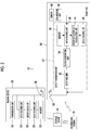
- Fig. 1 is a diagram schematically illustrating an information collection system according to an embodiment of the invention.
- An information collection system 10 illustrated in Fig. 1 includes an information collection unit 12, a storage device 14, and an information terminal 16.
- the information collection unit 12 and the storage device 14 are connected to each other wirelessly or in a wired manner.
- the storage device 14 and the information terminal 16 are connected to each other wirelessly or in a wired manner.
- various kinds of information which have been obtained from a radio tag 20 and have been collected by the information collection unit 12 are stored in the storage device 14.
- various kinds of information stored in the storage device 14 can be seen through the information terminal 16.
- the storage device 14 is not particularly limited as long as it can store various kinds of information which have been obtained from the radio tag 20 and have been collected by the information collection unit 12 and can transmit and receive data to and from the information collection unit 12 and the information terminal 16.
- the storage device 14 may be hardware, such as a server, or may be constructed on the Internet such as a cloud.
- various kinds of information obtained from the radio tag 20 are stored in time series for each identification information item of the radio tag 20.
- the configuration of the information terminal 16 is not particularly limited as long as the information terminal 16 can acquire the identification information of the radio tag 20 and can acquire the information which has been acquired from the radio tag 20, whose identification information has been acquired, and then stored in the storage device 14 from the storage device 14.
- the information terminal 16 may have a function of communicating with the radio tag 20 in order to acquire the identification information of the radio tag 20 and a function of communicating with the storage device 14 in order to acquire information from the storage device 14 and may include a display unit that visually displays the information stored in the storage device 14. Therefore, for example, an application for communication with the radio tag 20 and an application for communication with the storage device 14 are incorporated into a tablet personal computer or a smart phone such that the tablet personal computer or the smart phone can be used as the information terminal 16.
- the information terminal 16 may be a dedicated terminal that has the two communication functions implemented by hardware and software and includes the display unit which can visually display the information stored in the storage device 14.
- the information terminal 16 includes an imaging unit for reading the data code and image analysis software for recognizing the image of the data code acquired by the imaging unit.
- the data code is, for example, a bar code, characters, a symbol, or a combination of characters and a symbol.
- the data code is formed by, for example, printing.
- the information collection unit 12 includes a plurality of radio tags 20 and a reading device 22.
- a plurality of containers 24 are accommodated in a case 26.
- the radio tag 20 is provided in each container 24.
- the reading device 22 is accommodated in the case 26.
- the container 24 is not particularly limited and contains, for example, foods or beverages.
- Fig. 2 is a diagram schematically illustrating the configuration of the information collection system according to the embodiment of the invention.
- the radio tag 20 illustrated in Fig. 2 is a passive type, receives a power radio wave, that is, a carrier wave ⁇ c from the reading device 22, operates, and sends measurement data including the identification information of the radio tag 20 and information obtained by a sensor 40 to the reading device 22 with a natural period.
- the radio tags 20 have different natural periods. Therefore, the reading device 22 can acquire various kinds of information from the plurality of radio tags 20.
- the measurement data including the identification information of the radio tag 20 and the information obtained by the sensor 40 is simply referred to as measurement data.
- the radio tag 20 includes an antenna 30, a rectifying unit 32, a clock generation unit 34, a data reading unit 36, a memory 38, the sensor 40, a conversion unit 42, an error detection data calculation unit 44, and a data sending unit 46.
- the rectifying unit 32, the clock generation unit 34, the data reading unit 36, the memory 38, the error detection data calculation unit 44, and the data sending unit 46 form a data transmission unit 47.
- the antenna 30 is connected to the rectifying unit 32, and the rectifying unit 32 is connected to the clock generation unit 34.
- the clock generation unit 34 is connected to the data reading unit 36.
- the memory 38 is connected to the data reading unit 36.
- the sensor 40 is connected to the data reading unit 36 through the conversion unit 42.
- the error detection data calculation unit 44 is connected to the data reading unit 36, and the data sending unit 46 is connected to the error detection data calculation unit 44.
- the antenna 30 is used to receive the carrier wave ⁇ c for power supply from the reading device 22 and to transmit a radio wave ⁇ t from the radio tag 20.
- the configuration of the antenna 30 is not particularly limited as long as it can receive the carrier wave ⁇ c from the reading device 22 and transmit the radio wave ⁇ t from the radio tag 20, and various known antennas can be used.
- the carrier wave ⁇ c for power supply from the reading device 22 is, for example, an alternating-current radio wave with a frequency of 13.56 MHz.
- the frequency of the carrier wave ⁇ c is not limited to 13.56 MHz and is appropriately set according to, for example, the configuration of the radio tag 20.
- the frequency of the carrier wave ⁇ c is preferably equal to or greater than 13 MHz and more preferably 400 MHz, 900 MHz, and 2 GHz.
- the rectifying unit 32 converts the carrier wave ⁇ c which has been transmitted from the reading device 22 and then received by the antenna 30 into a direct-current voltage and obtains a power supply voltage of the radio tag 20.
- the rectifying unit 32 includes, for example, two rectifying transistors (not illustrated) and a capacitor (not illustrated).
- the capacitor is an output capacitor which accumulates charge.
- the two rectifying transistors are connected in series to each other and the capacitor is connected in parallel to the rectifying transistors connected in series to each other.
- the end of the rectifying transistor is grounded and the end of the rectifying transistor is connected to the clock generation unit 34.
- the rectifying unit 32 is not limited to the above-mentioned configuration as long as it can convert the carrier wave ⁇ c from the reading device 22 into a direct-current voltage.
- the clock generation unit 34 generates a clock signal of the radio tag 20.
- the clock generation unit 34 includes, for example, an oscillation circuit (not illustrated).
- the oscillation circuit generates the clock signal.
- the clock generation unit 34 is not limited to the oscillation circuit as long as it can generate the clock signal.
- a frequency dividing circuit (not illustrated) may generate the clock signal.
- the measurement data is sent on the basis of the clock signal.
- the frequency of the clock signal is, for example, 20 kHz. However, the frequency is not particularly limited to 20 kHz.
- the data reading unit 36 reads the identification information stored in the memory 38 and acquires the information obtained by the sensor 40 from the conversion unit 42. In addition, the data reading unit 36 outputs the read identification information stored in the memory 38 and the information obtained by the sensor 40 to the error detection data calculation unit 44.
- the configuration of the data reading unit 36 is not particularly limited as long as the data reading unit 36 has the above-mentioned functions.
- the memory 38 stores the identification information of the radio tag 20. In addition, the memory 38 stores the information obtained by the sensor 40.
- the memory 38 is not particularly limited as long as it can store the identification information of the radio tag 20 and the information obtained by the sensor 40.
- a rewritable memory is used as the memory 38.
- the configuration of the memory 38 is not particularly limited and various known memories can be used.
- a sensor corresponding to the purpose of the information collection system 10 can be appropriately used as the sensor 40.
- the sensor 40 is, for example, a temperature sensor.
- the sensor 40 is not limited to the temperature sensor.
- a pressure sensor, an optical sensor, an illuminance sensor, a humidity sensor, a gas sensor, an ultrasound sensor, a water sensor, a radiation sensor, a magnetic sensor, an odor sensor, a pH (hydrogen ion concentration index) sensor, a turbidity sensor, an altitude sensor, and an acceleration sensor can be used.
- the number of sensors 40 is not limited to 1.
- a plurality of sensors 40 may be used or a plurality of combinations of the above-mentioned various sensors may be used.
- the conversion unit 42 converts an analog signal obtained by the sensor 40 into a digital signal.
- the configuration of the conversion unit 42 is not particularly limited as long as the conversion unit 42 can convert an analog signal into a digital signal.
- the conversion unit 42 includes, for example, an 8-bit analog/digital conversion circuit. In a case in which the sensor 40 can output a digital signal, the conversion unit 42 may not be provided.
- the error detection data calculation unit 44 performs data calculation for error detection for the identification information stored in the memory 38 and the information obtained by the sensor 40 sent from the data reading unit 36. For example, a parity check method is used as the data calculation for error detection and a test bit is added to data. In addition, the error detection data calculation unit 44 adds a start of frame (SOF) that is required as a data start signal in the reading device 22 in series to the head of the data of the identification information and the information obtained by the sensor 40 and adds an end of frame (EOF) that is required as a data end signal in series to the end of the data of the information. As such, the error detection data calculation unit 44 processes data into a data format that can be read by the reading device 22, obtains the above-mentioned measurement data, and outputs the measurement data to the data sending unit 46.
- SOF start of frame
- EEF end of frame
- the data sending unit 46 sends the measurement data as the radio wave ⁇ t to the reading device 22 through the antenna 30.
- the data sending unit 46 modulates the measurement data and sends the measurement data as the radio wave ⁇ t from the antenna 30 on the basis of the clock signal of the clock generation unit 34.
- the radio tag 20 is not provided with a power supply and receives the carrier wave ⁇ c from the reading device 22.
- the rectifying unit 32 obtains a direct-current voltage and the clock generation unit 34 is driven to count the clocks of the clock signal.
- the radio tag 20 repeatedly sends data with the natural period until the clock generation unit 34 is not capable of being driven with the direct-current voltage obtained by the rectifying unit 32.
- the radio tag 20 has a configuration without a power supply.
- the invention is not limited thereto.
- a power supply may be provided and output may increase when data is sent from the data sending unit 46.
- a data sending range can be wider than that in a case in which the power supply is not provided.
- the natural periods are written to each radio tag 20 in order to check whether or not the natural period of a radio tag 20 is equal to the natural periods of other radio tags 20.
- a method for writing the natural period is not particularly limited.
- the natural period may be simply numbers or may be a data code (not illustrated) such as a bar code, as in the identification information. In a case in which numbers are written as the natural period, it is possible to visually check the natural period.
- the natural period is a data code such as a bar code
- a scanner can read the natural period and a computer can acquire the reading result to determine whether or not the natural periods of a plurality of radio tags 20 are equal to each other.
- the reading device 22 includes an antenna 50, a transmission unit 52, a data reading unit 54, an error check unit 56, a data sending unit 58, and a memory 59.
- the transmission unit 52 is connected to the antenna 50.
- the data reading unit 54 is connected to the antenna 50, and the error check unit 56 is connected to the data reading unit 54.
- the data sending unit 58 is connected to the error check unit 56.
- the memory 59 is connected to the data sending unit 58.
- the antenna 50 is used to transmit and receive data to and from the radio tag 20 and is used to transmit data to the storage device 14.
- the configuration of the antenna 50 is not particularly limited as long as the antenna 50 has the above-mentioned functions and various known antennas can be used as the antenna 50.
- the transmission unit 52 includes an oscillation circuit (not illustrated) that oscillates the carrier wave ⁇ c for supplying power to the radio tag 20.
- the configuration of the oscillation circuit is not particularly limited as long as the oscillation circuit can supply the carrier wave ⁇ c to the radio tag 20.
- a radio frequency (RF) circuit can be used.
- the carrier wave ⁇ c is oscillated by the transmission unit 52 and is transmitted to a plurality of radio tags 20 through the antenna 50 at the same time.
- the data reading unit 54 converts the radio wave ⁇ t which has been transmitted from the radio tag 20 and received by the antenna 50 into a format that can be used by the reading device 22 and reads the measurement data. Specifically, the data reading unit 54 demodulates the measurement data transmitted from the radio tag 20 into data that can be used by the error check unit 56 and reads the measurement data between the SOF and the EOF added by the error detection data calculation unit 44.
- a demodulation method is not particularly limited and various known demodulation methods can be used.
- the error check unit 56 checks whether there is an error in the measurement data which has been transmitted from the radio tag 20 and then demodulated by the data reading unit 54. As described above, the error detection data calculation unit 44 of the radio tag 20 adds a check bit to data using the parity check method. Therefore, the error check unit 56 uses, for example, a parity check method as the error check method. A known method can be used as the error detection method using the parity check method.
- the error check unit 56 detects no error
- the measurement data transmitted from the radio tag 20 is stored in the storage device 14.
- the error check unit 56 detects an error
- the measurement data transmitted from the radio tag 20 is not stored in the storage device 14.
- the error check unit 56 raises a flag in the data.
- raising a flag means that a "flag field” is set in data and the value of the "flag field” is set to "1".
- Data in which the value of the "flag field” is "0" is stored in the storage device 14. Whether data is stored in the storage device 14 can be represented by one bit “0” or “1". Data may be stored in the memory 59, regardless of the value of the "flag field", and data in which the value of the "flag field” is "0” may be stored in the storage device 14.
- the data sending unit 58 stores the measurement data which has been transmitted from the radio tag 20 and determined not to have an error by the error check unit 56 in the storage device 14. In a case in which the reading device 22 and the storage device 14 are connected to each other in a wired manner, the data sending unit 58 converts the measurement data transmitted from the radio tag 20 into a data format that can be stored in the storage device 14 and outputs the measurement data to the storage device 14.
- the data sending unit 58 modulates the measurement data transmitted from the radio tag 20 into a data format that can be transmitted by the antenna 50.
- a modulation method is not particularly limited and various known modulation methods can be used.
- the storage device 14 receives the data transmitted from the data sending unit 58 and, for example, stores the information obtained by the sensor 40 in time series for each unique information item of the radio tags 20. In this way, for example, the information obtained by the sensor 40 can be seen as time-series data through the information terminal 16.
- the data sending unit 58 may convert data into a data format that can be stored in the storage device 14 and may store the data in the memory 59.
- the memory 59 may be a detachable memory such as a memory card or a universal serial bus (USB) flash drive.
- USB universal serial bus
- the data to be stored in the storage device 14 can be collectively stored in the storage device 14.
- the memory 59 may not be provided.
- the interval at which data is sent from the data sending unit 58 of the reading device 22 is not particularly limited and may be appropriately set.
- the interval may be sent once per 2 hours.
- the reading device 22 transmits the carrier wave ⁇ c to the plurality of radio tags 20 at the same time. Since the plurality of radio tags 20 have different natural periods, they send data at different times after receiving the carrier wave ⁇ c. Therefore, the reading device 22 can collect the data from the plurality of radio tags 20.
- the radio tag 20 After receiving the carrier wave ⁇ c, the radio tag 20 repeatedly sends the measurement data with the natural period as long as it is driven by the direct-current voltage obtained by the carrier wave ⁇ c.
- the reading device 22 can obtain data from the plurality of radio tags 20 only by transmitting the carrier wave ⁇ c to the plurality of radio tags 20, without transmitting a command signal.
- the radio tag 20 is driven by the direct-current voltage obtained from the carrier wave ⁇ c, has a simple configuration, and has a low cost.
- the time when the reading device 22 transmits the carrier wave ⁇ c is appropriately determined according to, for example, the purpose and is changed if necessary. For example, the reading device 22 transmits the carrier wave ⁇ c once per hour.
- the radio tag 20 continuously transmits data as long as it is driven by the direct-current voltage obtained from the carrier wave ⁇ c once per hour.
- the operation of the information collection system 10 will be described using three radio tags 20a, 20b, and 20c as an example.
- An example in which the sensors 40 of the three radio tags 20a, 20b, and 20c are temperature sensors and both temperature information and identification information are sent as the measurement data will be described.
- Fig. 3 is a diagram schematically illustrating the operation of the information collection system according to the embodiment of the invention.
- Fig. 4 is a diagram schematically illustrating the timing chart of the information collection system according to the embodiment of the invention.
- Fig. 5 is a diagram schematically illustrating another example of the timing chart of the radio tags.
- reference numeral 21A indicates the timing chart of the radio tag 20a
- reference numeral 21B indicates the timing chart of the radio tag 20b
- reference numeral 21C indicates the timing chart of the radio tag 20c.
- the three radio tags 20a, 20b, and 20c have the clock signals with the same frequency, send the measurement data at the same time t d , and send the measurement data with different natural periods.
- the natural period of the radio tag 20a is T 1
- the natural period of the radio tag 20b is T 2
- the natural period of the radio tag 20c is T 3 .
- the ratio of the natural periods of the radio tag 20a, the radio tag 20b, and the radio tag 20c is 7:8:9.
- the reading device 22 transmits the carrier wave ⁇ c to the radio tags 20a to 20c at the same time.
- the rectifying unit 32 obtains a voltage from the carrier wave ⁇ c and the clock generation unit 34 generates a clock signal.
- the data reading unit 36 acquires the identification information stored in the memory 38 and the temperature information obtained by the sensor 40.
- the data reading unit 36 reads data at the time when the clock signal starts to be generated or the time when a signal is transmitted from a dedicated start signal generation circuit.
- the error detection data calculation unit 44 processes the data of the identification information stored in the memory 38 and the information obtained by the sensor 40 into a data format that can be read by the reading device 22 and obtains the above-mentioned measurement data.
- the measurement data is output to the data sending unit 46.
- the information obtained by the sensor 40 is temporarily stored in the memory 38 or is directly transmitted to the error detection data calculation unit 44.
- the data sending units 46 modulate the measurement data and send the measurement data as radio waves ⁇ ta, ⁇ tb, and ⁇ tc from the antennas 30 on the basis of the clock signals of the clock generation units 34.
- the radio tags 20a to 20c have different natural periods T 1 to T 3 , the count values of the clocks of the clock signals until the measurement data is sent are different from each other. As described above, the radio tags 20a to 20c send the measurement data at the same time t d and the ratio of the count values is 7:8:9 from the ratio of the natural periods.
- the radio tags 20a to 20c after counting a predetermined number of clocks on the basis of the natural periods T 1 to T 3 , the radio tags 20a to 20c send the measurement data at the time t d .
- the radio tag 20a sends the measurement data at the time t d after a time t c1 when a predetermined number of clocks are counted within the natural period T 1 , as represented by the reference numeral 21A in Fig. 4 .
- the radio tag 20b sends the measurement data at the time t d after a time t c2 when a predetermined number of clocks are counted within the natural period T 2 , as represented by the reference numeral 21B in Fig. 4 .
- the radio tag 20c sends the measurement data at the time t d after is a time t c3 when a predetermined number of clocks are counted within the natural period T 3 , as represented by the reference numeral 21C in Fig. 4 .
- the radio tag 20a and the radio tag 20b start to send the measurement data at the time represented by reference numeral 60.
- the reading device 22 receives two measurement data items at the same time and is not capable of identifying the measurement data items sent from the radio tags. Therefore, the reading device 22 does not process the measurement data items.
- the radio tag 20b and the radio tag 20c start to send the measurement data at the time represented by reference numeral 62.
- the reading device 22 receives two measurement data items at the same time and is not capable of identifying the measurement data items sent from the radio tags. Therefore, the reading device 22 does not process the measurement data items. As such, even in a case in which the natural periods are different from each other, the measurement data items are likely to be sent at the same time according to the period. In this case, the sent measurement data items are not stored in the storage device 14 and are not used. For this reason, for example, the frequency of the transmission of the carrier wave ⁇ c from the reading device 22 increases to compensate for the loss of the measurement data.
- the radio tags 20a to 20c have the same natural period T 4 . As illustrated in Fig. 5 , the radio tags 20a to 20c send the measurement data at the time t d after a time t c4 when a predetermined number of clocks are counted within the natural period T 4 . However, in a case in which the times when data is sent deviate from each other, the reading device 22 can receive the measurement data from the radio tags 20a to 20c. In order to shift the initial data sending time of the radio tags 20a to 20c, it is necessary to provide a program for delaying the initial data sending time of the radio tags 20a to 20c and sending data at a specific interval after the initial data sending, which results in an increase in costs.
- reference numeral 23A indicates the timing chart of the radio tag 20a
- reference numeral 23B indicates the timing chart of the radio tag 20b
- reference numeral 23C indicates the timing chart of the radio tag 20c.
- the radio tags 20 are attached to a plurality of containers 24 and the temperature of each container 24 can be measured.
- the reading device 22 simultaneously transmits the carrier wave ⁇ c to a plurality of radio tags 20 at a predetermined time interval. Therefore, it is possible to obtain the temperature information of each container 24 in time series and the temperature of each container 24 is stored in time series in the storage device 14.
- the information terminal 16 reads the radio tag 20 attached to the container 24. With this configuration, it is possible to see the time-series temperature information stored in the storage device 14 and the temperature history of the container 24 is known. Therefore, for example, it is possible to know whether the container 24 has been preserved or transported in an appropriate temperature range. As a result, the information collection system 10 can be used to manage the temperature of, for example, food.
- the natural period of the radio tag is set on the basis of the number of radio tags n.
- the number of radio tags n is 3, 6t d ⁇ T is satisfied. In a case in which the number of radio tags n is 10, 90t d ⁇ T is satisfied. In a case in which the number of radio tags n is 50, 2450t d ⁇ T is satisfied.
- the time t d when the measurement data is sent is determined according to the amount of measurement data. In a case in which the measurement target is the same and, for example, temperature is measured, the radio tags send the measurement data at the same time t d . In this case, as the number of radio tags n becomes larger, the natural period becomes longer. As described above, a plurality of radio tags have different natural periods.
- the ratio of the natural periods T of each radio tag 20 can be represented by the ratio of the times until the measurement data is initially sent based on one radio tag 20.
- the ratio of the natural periods T of each radio tag 20 is the ratio of integers in order to simplify the configuration of each radio tag 20.
- the ratio of the natural periods T is preferably the ratio of prime numbers. It is more preferable that the ratio of any two natural periods T is the ratio of prime numbers. In this case, it is possible to prevent the measurement data from being sent at the same time.
- the radio tags 20 measure the temperature of each of a plurality of containers 24 and the reading device 22 reads the measurement result of the temperature and stores the measurement result in the storage device 14 has been described.
- the radio tag may not be provided in the container 24, but may be directly attached to a measurement target.
- the radio tag may measure, for example, the humidity of the container 24 instead of the temperature or may measure both the temperature and the humidity.
- An imaging element may be used as the sensor and the reading device 22 may read an image obtained by the imaging element and store the image in the storage device 14.
- the radio tag may be used as a surveillance camera.
- An illuminance sensor may be used as the sensor, a plurality of radio tags 20 may be provided in a farm, and the reading device 22 may read the sunshine data of the farm and store the sunshine data in the storage device 14. It is possible to investigate a place with a good sunshine situation and a good sunshine condition on the farm.
- a temperature sensor may be used as the sensor, the radio tag 20 may be provided in a vinyl greenhouse, and the reading device 22 may read temperature data in the vinyl greenhouse and store the temperature data in the storage device 14. It is possible to investigate a temperature distribution and a temperature variation in the vinyl greenhouse.
- An acceleration sensor may be used as the sensor, the radio tags 20 may be provided in a plurality of containers 24, and the reading device 22 may read acceleration data and store the acceleration data in the storage device 14. It is possible to investigate the shaking state of the container 24 during conveyance.
- a radiation sensor may be used as the sensor and the reading device 22 may read the data of the amount of radiation at a plurality of positions and store the data in the storage device 14. In this case, it is possible to investigate the distribution of the amount of radiation and a variation in the amount of radiation. Furthermore, in a case in which the radiation sensor is used as the sensor and the radio tag 20 is attached to the container 24, it is possible to investigate, for example, the leakage of radiation from the container 24.
- a temperature sensor may be used as the sensor to measure, for example, the temperature of a plurality of parts of an animal and a person and the temperature of clothes.
- a pressure sensor is used as the sensor, it is possible to measure, for example, the blood pressure of a plurality of parts of a person.
- the radio tag 20 includes, for example, a plurality of transistors.
- the transistor is not particularly limited and is, for example, a transistor that is formed on a silicon substrate.
- the radio tag 20 is a thin film transistor (TFT) (hereinafter, simply referred to as a coating-type TFT) in which a coating-type semiconductor is included in a semiconductor active layer.
- TFT thin film transistor
- the coating-type TFT has the advantages that it is manufactured at a low temperature and it can be formed by printing. Therefore, it is possible to manufacture the coating-type TFT at a low cost using a resin substrate. In addition, in a case in which coating is used, it is possible to manufacture sensors at the same time. Therefore, it is possible to reduce the manufacturing cost of the radio tag 20.
- the coating-type TFT is provided with the semiconductor active layer including the coating-type semiconductor.
- the coating-type TFT may include layers other than the semiconductor active layer.
- the coating-type TFT is preferably an organic field effect transistor (hereinafter, simply referred to as an FET) and more preferably an insulated-gate FET in which a gate and a channel are insulated from each other.
- an FET organic field effect transistor
- the structure of the coating-type TFT is not particularly limited and may be various known structures.
- Examples of the structure of the coating-type TFT include a structure in which an electrode, an insulating layer, a semiconductor active layer (organic semiconductor layer), and two electrodes are sequentially provided on an upper surface of a substrate in the lowest layer and a bottom-gate top-contact structure.
- the electrode on the upper surface of the substrate in the lowest layer is provided in a portion of the substrate and the insulating layer is provided so as to come into contact with a portion of the substrate other than the electrode.
- the two electrodes provided on the upper surface of the semiconductor active layer are provided so as to be separated from each other.
- the structure may be a top-gate top-contact structure.
- the transistor forming the radio tag 20 may be a transistor in which a semiconductor layer is made of, for example, an organic semiconductor or an inorganic semiconductor.
- the transistor having the semiconductor layer made of an organic semiconductor has the advantage that it can be formed by printing. Therefore, it is preferable that the radio tag 20 includes the transistor having the semiconductor layer made of an organic semiconductor.
- the semiconductor layer is made of an organic semiconductor, it is easy to manufacture the semiconductor layer, bendability is high, and coating can be performed.
- Examples of the organic semiconductor forming the semiconductor layer include a pentacene derivative, such as 6,13-bis(triisopropylsilylethynyl) pentacene (TIPS pentacene), an anthradithiophene derivative, such as 5,11-bis(triethylsilylethynyl) anthradithiophene (TES-ADT), a benzodithiophene (BDT) derivative, a benzothienobenzothiophene (BTBT) derivative, such as dioctylbenzothienobenzothiophene (C8-BTBT), a dinaphthothienothiophene (DNTT) derivative, a dinaphthobenzodithiophene (DNBDT) derivative, a 6,12-dioxaanthanthrene (perixanthenoxanthene) derivative, a naphthalene tetracarboxylic acid diimide (NT
- fullerenes in general, fullerenes, a naphthalene tetracarboxylic acid diimide (NTCDI) derivative, a perylene tetracarboxylic acid diimide (PTCDI) derivative, and a tetracyanoquinodimethane (TCNQ) derivative are used for an N-type organic semiconductor layer and the others are used for a P-type organic semiconductor layer.
- NCDI naphthalene tetracarboxylic acid diimide
- PTCDI perylene tetracarboxylic acid diimide
- TCNQ tetracyanoquinodimethane
- the above-mentioned organic semiconductor becomes a P type or an N type depending on the derivative.
- a method for forming the semiconductor layer is not particularly limited.
- known methods such as a coating method, a transfer method, and a vapor deposition method, can be appropriately used.
- the thickness of the semiconductor layer is preferably in the range of 1 nm to 1000 nm and more preferably in the range of 10 nm to 300 nm, considering, for example, film formability.
- Oxide semiconductors such as silicon, zinc oxide (ZnO), and In-Ga-ZnO 4 , can be used as the inorganic semiconductor forming the semiconductor layer.
- a method for forming the semiconductor layer is not particularly limited.
- a coating method and vacuum film forming methods such as a vacuum vapor position method and a chemical vapor deposition method, can be used.
- cyclopentasilane can be used.
- the invention basically has the above-mentioned configuration.
- the information collection system according to the invention has been described in detail above.
- the invention is not limited to the above-described embodiment and various modifications or changes of the invention can be made without departing from the scope and spirit of the invention.
Landscapes
- Engineering & Computer Science (AREA)
- Physics & Mathematics (AREA)
- Health & Medical Sciences (AREA)
- Toxicology (AREA)
- Theoretical Computer Science (AREA)
- General Physics & Mathematics (AREA)
- Computer Vision & Pattern Recognition (AREA)
- Artificial Intelligence (AREA)
- General Health & Medical Sciences (AREA)
- Electromagnetism (AREA)
- Computer Networks & Wireless Communication (AREA)
- Computer Hardware Design (AREA)
- Microelectronics & Electronic Packaging (AREA)
- Computer Security & Cryptography (AREA)
- General Engineering & Computer Science (AREA)
- Signal Processing (AREA)
- Arrangements For Transmission Of Measured Signals (AREA)
Abstract
Description
- The present invention relates to an information collection system including a plurality of radio tags, and more particularly, to an information collection system that obtains information from a plurality of radio tags without a command signal.
- In recent years, a technique has been known which provides a radio tag that is called, for example, an integrated circuit tag (IC tag), an electronic tag, or a radio frequency identification (RFID) tag in an object, reads information recorded on the radio tag with a reading device, and recognizes various kinds of information related to the object.
- For example, in an item management system disclosed in
JP2008-24385A - The radio IC tag with a sensor has a watchdog timer function. The radio IC tag with a sensor measures the ambient temperature of an item at a predetermined time using the watchdog timer function and autonomously transmits ambient temperature data to the logging device whenever measuring the ambient temperature. Therefore, the radio IC tag with a sensor does not need to receive, for example, a request signal for transmitting the ambient temperature data to the logging device from the logging device.
- The ambient temperature data of the item measured by the radio IC tag with a sensor is stored in a memory of the logging device so as to be associated with the identification (ID) information of the radio IC tag with a sensor which is the transmission source of the ambient temperature data. Therefore, in a case in which the ID of the radio IC tag with a sensor and the item to which the radio IC tag with a sensor is added are managed so as to be associated with each other, it is possible to store the ambient temperature data of the items measured by a plurality of radio IC tags with a sensor such that the items can be specified.
- In the item management system disclosed in
JP2008-24385A - An object of the invention is to provide an information collection system that can solve the above-mentioned problems of the related art, can obtain information from a plurality of radio tags without a command signal, and has a simple configuration and a low cost.
- In order to achieve the object, there is provided an information collection system comprising a plurality of radio tags and a reading device. Each of the radio tags stores identification information and includes a sensor, an antenna that receives a carrier wave from the reading device, and a data transmission unit that sends measurement data including the identification information and information obtained by the sensor to the reading device after the carrier wave is received by the antenna. The plurality of radio tags send the identification information and the information obtained by the sensor with different natural periods from the data transmission units. The reading device transmits the carrier wave to each of the radio tags, receives the measurement data from each of the radio tags, and obtains the measurement data.
- Preferably, the information collection system further comprises a storage device and the measurement data obtained by the reading device from the plurality of radio tags is stored in the storage device.
- Preferably, the information collection system further comprises an information terminal that reads the identification information of the radio tag and reads the information obtained by the sensor of the radio tag, whose identification information has been read, from the storage device in time series.
- Preferably, in a case in which the number of radio tags is n, a time when the measurement data is sent is td, and the natural period of the radio tag is T, (n2-n)×td ≤ T is satisfied.
- A carrier frequency of the carrier wave of the reading device is preferably equal to or greater than 13 MHz, more preferably equal to or greater than 13.56 MHz, and most preferably 400 MHz, 900 MHz, and 2 GHz.
- Preferably, the radio tag includes a transistor in which a semiconductor layer is made of an organic semiconductor.
- According to the invention, it is possible to obtain information from a plurality of radio tags without a command signal, to simplify the configuration of the radio tag, and to reduce the cost of the radio tag.
-
-
Fig. 1 is a diagram schematically illustrating an information collection system according to an embodiment of the invention; -
Fig. 2 is a diagram schematically illustrating the configuration of the information collection system according to the embodiment of the invention; -
Fig. 3 is a diagram schematically illustrating the operation of the information collection system according to the embodiment of the invention; -
Fig. 4 is a diagram schematically illustrating a timing chart of the information collection system according to the embodiment of the invention; -
Fig. 5 is a diagram schematically illustrating another example of a timing chart of a radio tag. - Hereinafter, an information collection system according to the invention will be described in detail on the basis of a preferred embodiment illustrated in the accompanying drawings.
- In the following description, "to" indicating a value range includes the upper and lower limits of the range. For example, in a case in which ε is in the range from a value α to a value β, the range of ε includes the value α and the value β, which is mathematically represented by α ≤ ε ≤ β.
-
Fig. 1 is a diagram schematically illustrating an information collection system according to an embodiment of the invention. - An
information collection system 10 illustrated inFig. 1 includes aninformation collection unit 12, astorage device 14, and aninformation terminal 16. Theinformation collection unit 12 and thestorage device 14 are connected to each other wirelessly or in a wired manner. Thestorage device 14 and theinformation terminal 16 are connected to each other wirelessly or in a wired manner. - In the
information collection system 10, various kinds of information which have been obtained from aradio tag 20 and have been collected by theinformation collection unit 12 are stored in thestorage device 14. Various kinds of information stored in thestorage device 14 can be seen through theinformation terminal 16. - The
storage device 14 is not particularly limited as long as it can store various kinds of information which have been obtained from theradio tag 20 and have been collected by theinformation collection unit 12 and can transmit and receive data to and from theinformation collection unit 12 and theinformation terminal 16. Thestorage device 14 may be hardware, such as a server, or may be constructed on the Internet such as a cloud. - In the
storage device 14, various kinds of information obtained from theradio tag 20 are stored in time series for each identification information item of theradio tag 20. - The configuration of the
information terminal 16 is not particularly limited as long as theinformation terminal 16 can acquire the identification information of theradio tag 20 and can acquire the information which has been acquired from theradio tag 20, whose identification information has been acquired, and then stored in thestorage device 14 from thestorage device 14. For example, theinformation terminal 16 may have a function of communicating with theradio tag 20 in order to acquire the identification information of theradio tag 20 and a function of communicating with thestorage device 14 in order to acquire information from thestorage device 14 and may include a display unit that visually displays the information stored in thestorage device 14. Therefore, for example, an application for communication with theradio tag 20 and an application for communication with thestorage device 14 are incorporated into a tablet personal computer or a smart phone such that the tablet personal computer or the smart phone can be used as theinformation terminal 16. In addition, theinformation terminal 16 may be a dedicated terminal that has the two communication functions implemented by hardware and software and includes the display unit which can visually display the information stored in thestorage device 14. - In a case in which the identification information of the
radio tag 20 is attached as a data code (not illustrated) to theradio tag 20, theinformation terminal 16 includes an imaging unit for reading the data code and image analysis software for recognizing the image of the data code acquired by the imaging unit. - The data code is, for example, a bar code, characters, a symbol, or a combination of characters and a symbol. The data code is formed by, for example, printing.
- The
information collection unit 12 includes a plurality ofradio tags 20 and areading device 22. - For example, a plurality of
containers 24 are accommodated in acase 26. Theradio tag 20 is provided in eachcontainer 24. For example, thereading device 22 is accommodated in thecase 26. - The
container 24 is not particularly limited and contains, for example, foods or beverages. - Here,
Fig. 2 is a diagram schematically illustrating the configuration of the information collection system according to the embodiment of the invention. - The
radio tag 20 illustrated inFig. 2 is a passive type, receives a power radio wave, that is, a carrier wave ωc from thereading device 22, operates, and sends measurement data including the identification information of theradio tag 20 and information obtained by asensor 40 to thereading device 22 with a natural period. Theradio tags 20 have different natural periods. Therefore, thereading device 22 can acquire various kinds of information from the plurality ofradio tags 20. Hereinafter, the measurement data including the identification information of theradio tag 20 and the information obtained by thesensor 40 is simply referred to as measurement data. - The
radio tag 20 includes anantenna 30, a rectifyingunit 32, aclock generation unit 34, adata reading unit 36, amemory 38, thesensor 40, aconversion unit 42, an error detectiondata calculation unit 44, and adata sending unit 46. The rectifyingunit 32, theclock generation unit 34, thedata reading unit 36, thememory 38, the error detectiondata calculation unit 44, and thedata sending unit 46 form adata transmission unit 47. - The
antenna 30 is connected to the rectifyingunit 32, and the rectifyingunit 32 is connected to theclock generation unit 34. Theclock generation unit 34 is connected to thedata reading unit 36. Thememory 38 is connected to thedata reading unit 36. Thesensor 40 is connected to thedata reading unit 36 through theconversion unit 42. In addition, the error detectiondata calculation unit 44 is connected to thedata reading unit 36, and thedata sending unit 46 is connected to the error detectiondata calculation unit 44. - The
antenna 30 is used to receive the carrier wave ωc for power supply from thereading device 22 and to transmit a radio wave ωt from theradio tag 20. The configuration of theantenna 30 is not particularly limited as long as it can receive the carrier wave ωc from thereading device 22 and transmit the radio wave ωt from theradio tag 20, and various known antennas can be used. - The carrier wave ωc for power supply from the
reading device 22 is, for example, an alternating-current radio wave with a frequency of 13.56 MHz. The frequency of the carrier wave ωc is not limited to 13.56 MHz and is appropriately set according to, for example, the configuration of theradio tag 20. The frequency of the carrier wave ωc is preferably equal to or greater than 13 MHz and more preferably 400 MHz, 900 MHz, and 2 GHz. - The rectifying
unit 32 converts the carrier wave ωc which has been transmitted from thereading device 22 and then received by theantenna 30 into a direct-current voltage and obtains a power supply voltage of theradio tag 20. The rectifyingunit 32 includes, for example, two rectifying transistors (not illustrated) and a capacitor (not illustrated). The capacitor is an output capacitor which accumulates charge. In the rectifyingunit 32, the two rectifying transistors are connected in series to each other and the capacitor is connected in parallel to the rectifying transistors connected in series to each other. In the two rectifying transistors connected in series to each other, the end of the rectifying transistor is grounded and the end of the rectifying transistor is connected to theclock generation unit 34. In this way, the direct-current voltage obtained by the rectifyingunit 32 can be supplied to theclock generation unit 34. The rectifyingunit 32 is not limited to the above-mentioned configuration as long as it can convert the carrier wave ωc from thereading device 22 into a direct-current voltage. - The
clock generation unit 34 generates a clock signal of theradio tag 20. Theclock generation unit 34 includes, for example, an oscillation circuit (not illustrated). The oscillation circuit generates the clock signal. Theclock generation unit 34 is not limited to the oscillation circuit as long as it can generate the clock signal. A frequency dividing circuit (not illustrated) may generate the clock signal. The measurement data is sent on the basis of the clock signal. The frequency of the clock signal is, for example, 20 kHz. However, the frequency is not particularly limited to 20 kHz. - The
data reading unit 36 reads the identification information stored in thememory 38 and acquires the information obtained by thesensor 40 from theconversion unit 42. In addition, thedata reading unit 36 outputs the read identification information stored in thememory 38 and the information obtained by thesensor 40 to the error detectiondata calculation unit 44. - The configuration of the
data reading unit 36 is not particularly limited as long as thedata reading unit 36 has the above-mentioned functions. - The
memory 38 stores the identification information of theradio tag 20. In addition, thememory 38 stores the information obtained by thesensor 40. Thememory 38 is not particularly limited as long as it can store the identification information of theradio tag 20 and the information obtained by thesensor 40. A rewritable memory is used as thememory 38. The configuration of thememory 38 is not particularly limited and various known memories can be used. - A sensor corresponding to the purpose of the
information collection system 10 can be appropriately used as thesensor 40. Thesensor 40 is, for example, a temperature sensor. Thesensor 40 is not limited to the temperature sensor. For example, a pressure sensor, an optical sensor, an illuminance sensor, a humidity sensor, a gas sensor, an ultrasound sensor, a water sensor, a radiation sensor, a magnetic sensor, an odor sensor, a pH (hydrogen ion concentration index) sensor, a turbidity sensor, an altitude sensor, and an acceleration sensor can be used. The number ofsensors 40 is not limited to 1. A plurality ofsensors 40 may be used or a plurality of combinations of the above-mentioned various sensors may be used. - The
conversion unit 42 converts an analog signal obtained by thesensor 40 into a digital signal. The configuration of theconversion unit 42 is not particularly limited as long as theconversion unit 42 can convert an analog signal into a digital signal. Theconversion unit 42 includes, for example, an 8-bit analog/digital conversion circuit. In a case in which thesensor 40 can output a digital signal, theconversion unit 42 may not be provided. - The error detection
data calculation unit 44 performs data calculation for error detection for the identification information stored in thememory 38 and the information obtained by thesensor 40 sent from thedata reading unit 36. For example, a parity check method is used as the data calculation for error detection and a test bit is added to data. In addition, the error detectiondata calculation unit 44 adds a start of frame (SOF) that is required as a data start signal in thereading device 22 in series to the head of the data of the identification information and the information obtained by thesensor 40 and adds an end of frame (EOF) that is required as a data end signal in series to the end of the data of the information. As such, the error detectiondata calculation unit 44 processes data into a data format that can be read by thereading device 22, obtains the above-mentioned measurement data, and outputs the measurement data to thedata sending unit 46. - The
data sending unit 46 sends the measurement data as the radio wave ωt to thereading device 22 through theantenna 30. Thedata sending unit 46 modulates the measurement data and sends the measurement data as the radio wave ωt from theantenna 30 on the basis of the clock signal of theclock generation unit 34. Theradio tag 20 is not provided with a power supply and receives the carrier wave ωc from thereading device 22. The rectifyingunit 32 obtains a direct-current voltage and theclock generation unit 34 is driven to count the clocks of the clock signal. Theradio tag 20 repeatedly sends data with the natural period until theclock generation unit 34 is not capable of being driven with the direct-current voltage obtained by the rectifyingunit 32. - The
radio tag 20 has a configuration without a power supply. However, the invention is not limited thereto. For example, a power supply may be provided and output may increase when data is sent from thedata sending unit 46. In this case, a data sending range can be wider than that in a case in which the power supply is not provided. - For example, the natural periods are written to each
radio tag 20 in order to check whether or not the natural period of aradio tag 20 is equal to the natural periods of other radio tags 20. A method for writing the natural period is not particularly limited. The natural period may be simply numbers or may be a data code (not illustrated) such as a bar code, as in the identification information. In a case in which numbers are written as the natural period, it is possible to visually check the natural period. In a case in which the natural period is a data code such as a bar code, a scanner can read the natural period and a computer can acquire the reading result to determine whether or not the natural periods of a plurality ofradio tags 20 are equal to each other. - Next, the
reading device 22 will be described. - The
reading device 22 includes anantenna 50, atransmission unit 52, adata reading unit 54, anerror check unit 56, adata sending unit 58, and amemory 59. Thetransmission unit 52 is connected to theantenna 50. In addition, thedata reading unit 54 is connected to theantenna 50, and theerror check unit 56 is connected to thedata reading unit 54. Thedata sending unit 58 is connected to theerror check unit 56. Thememory 59 is connected to thedata sending unit 58. - The
antenna 50 is used to transmit and receive data to and from theradio tag 20 and is used to transmit data to thestorage device 14. The configuration of theantenna 50 is not particularly limited as long as theantenna 50 has the above-mentioned functions and various known antennas can be used as theantenna 50. - The
transmission unit 52 includes an oscillation circuit (not illustrated) that oscillates the carrier wave ωc for supplying power to theradio tag 20. The configuration of the oscillation circuit is not particularly limited as long as the oscillation circuit can supply the carrier wave ωc to theradio tag 20. For example, a radio frequency (RF) circuit can be used. The carrier wave ωc is oscillated by thetransmission unit 52 and is transmitted to a plurality ofradio tags 20 through theantenna 50 at the same time. - The
data reading unit 54 converts the radio wave ωt which has been transmitted from theradio tag 20 and received by theantenna 50 into a format that can be used by thereading device 22 and reads the measurement data. Specifically, thedata reading unit 54 demodulates the measurement data transmitted from theradio tag 20 into data that can be used by theerror check unit 56 and reads the measurement data between the SOF and the EOF added by the error detectiondata calculation unit 44. A demodulation method is not particularly limited and various known demodulation methods can be used. - The
error check unit 56 checks whether there is an error in the measurement data which has been transmitted from theradio tag 20 and then demodulated by thedata reading unit 54. As described above, the error detectiondata calculation unit 44 of theradio tag 20 adds a check bit to data using the parity check method. Therefore, theerror check unit 56 uses, for example, a parity check method as the error check method. A known method can be used as the error detection method using the parity check method. - In a case in which the
error check unit 56 detects no error, the measurement data transmitted from theradio tag 20 is stored in thestorage device 14. On the other hand, in a case in which theerror check unit 56 detects an error, the measurement data transmitted from theradio tag 20 is not stored in thestorage device 14. - In a case in which an error is detected from the data, the
error check unit 56 raises a flag in the data. Here, the term "raising a flag" means that a "flag field" is set in data and the value of the "flag field" is set to "1". Data in which the value of the "flag field" is "0" is stored in thestorage device 14. Whether data is stored in thestorage device 14 can be represented by one bit "0" or "1". Data may be stored in thememory 59, regardless of the value of the "flag field", and data in which the value of the "flag field" is "0" may be stored in thestorage device 14. - The
data sending unit 58 stores the measurement data which has been transmitted from theradio tag 20 and determined not to have an error by theerror check unit 56 in thestorage device 14. In a case in which thereading device 22 and thestorage device 14 are connected to each other in a wired manner, thedata sending unit 58 converts the measurement data transmitted from theradio tag 20 into a data format that can be stored in thestorage device 14 and outputs the measurement data to thestorage device 14. - On the other hand, in a case in which the
reading device 22 and thestorage device 14 are wirelessly connected to each other, thedata sending unit 58 modulates the measurement data transmitted from theradio tag 20 into a data format that can be transmitted by theantenna 50. A modulation method is not particularly limited and various known modulation methods can be used. Thestorage device 14 receives the data transmitted from thedata sending unit 58 and, for example, stores the information obtained by thesensor 40 in time series for each unique information item of the radio tags 20. In this way, for example, the information obtained by thesensor 40 can be seen as time-series data through theinformation terminal 16. - In the
reading device 22, thedata sending unit 58 may convert data into a data format that can be stored in thestorage device 14 and may store the data in thememory 59. In this case, thememory 59 may be a detachable memory such as a memory card or a universal serial bus (USB) flash drive. In this case, the data to be stored in thestorage device 14 can be collectively stored in thestorage device 14. In addition, thememory 59 may not be provided. - The interval at which data is sent from the
data sending unit 58 of thereading device 22 is not particularly limited and may be appropriately set. For example, the interval may be sent once per 2 hours. - The
reading device 22 transmits the carrier wave ωc to the plurality ofradio tags 20 at the same time. Since the plurality ofradio tags 20 have different natural periods, they send data at different times after receiving the carrier wave ωc. Therefore, thereading device 22 can collect the data from the plurality of radio tags 20. - After receiving the carrier wave ωc, the
radio tag 20 repeatedly sends the measurement data with the natural period as long as it is driven by the direct-current voltage obtained by the carrier wave ωc. - In the
information collection system 10, thereading device 22 can obtain data from the plurality ofradio tags 20 only by transmitting the carrier wave ωc to the plurality ofradio tags 20, without transmitting a command signal. Theradio tag 20 is driven by the direct-current voltage obtained from the carrier wave ωc, has a simple configuration, and has a low cost. - The time when the
reading device 22 transmits the carrier wave ωc is appropriately determined according to, for example, the purpose and is changed if necessary. For example, thereading device 22 transmits the carrier wave ωc once per hour. Theradio tag 20 continuously transmits data as long as it is driven by the direct-current voltage obtained from the carrier wave ωc once per hour. - Next, the operation of the
information collection system 10 will be described using threeradio tags sensors 40 of the threeradio tags -
Fig. 3 is a diagram schematically illustrating the operation of the information collection system according to the embodiment of the invention.Fig. 4 is a diagram schematically illustrating the timing chart of the information collection system according to the embodiment of the invention.Fig. 5 is a diagram schematically illustrating another example of the timing chart of the radio tags. - In
Fig. 4 ,reference numeral 21A indicates the timing chart of theradio tag 20a,reference numeral 21B indicates the timing chart of theradio tag 20b, and reference numeral 21C indicates the timing chart of theradio tag 20c. The threeradio tags radio tag 20a is T1, the natural period of theradio tag 20b is T2, and the natural period of theradio tag 20c is T3. For example, the ratio of the natural periods of theradio tag 20a, theradio tag 20b, and theradio tag 20c is 7:8:9. - As illustrated in
Fig. 3 , thereading device 22 transmits the carrier wave ωc to theradio tags 20a to 20c at the same time. - In each of the
radio tags 20a to 20c, the rectifyingunit 32 obtains a voltage from the carrier wave ωc and theclock generation unit 34 generates a clock signal. Thedata reading unit 36 acquires the identification information stored in thememory 38 and the temperature information obtained by thesensor 40. Thedata reading unit 36 reads data at the time when the clock signal starts to be generated or the time when a signal is transmitted from a dedicated start signal generation circuit. - Then, the error detection
data calculation unit 44 processes the data of the identification information stored in thememory 38 and the information obtained by thesensor 40 into a data format that can be read by thereading device 22 and obtains the above-mentioned measurement data. The measurement data is output to thedata sending unit 46. The information obtained by thesensor 40 is temporarily stored in thememory 38 or is directly transmitted to the error detectiondata calculation unit 44. Thedata sending units 46 modulate the measurement data and send the measurement data as radio waves ωta, ωtb, and ωtc from theantennas 30 on the basis of the clock signals of theclock generation units 34. - As described above, since the
radio tags 20a to 20c have different natural periods T1 to T3, the count values of the clocks of the clock signals until the measurement data is sent are different from each other. As described above, theradio tags 20a to 20c send the measurement data at the same time td and the ratio of the count values is 7:8:9 from the ratio of the natural periods. - As illustrated in
Fig. 4 , after counting a predetermined number of clocks on the basis of the natural periods T1 to T3, theradio tags 20a to 20c send the measurement data at the time td. Theradio tag 20a sends the measurement data at the time td after a time tc1 when a predetermined number of clocks are counted within the natural period T1, as represented by thereference numeral 21A inFig. 4 . Theradio tag 20b sends the measurement data at the time td after a time tc2 when a predetermined number of clocks are counted within the natural period T2, as represented by thereference numeral 21B inFig. 4 . Theradio tag 20c sends the measurement data at the time td after is a time tc3 when a predetermined number of clocks are counted within the natural period T3, as represented by thereference numeral 21C inFig. 4 . - The natural period T of the radio tag is the sum of the time tc when the number of clocks is counted and the time td when the measurement data is sent. That is, T = tc+td is established. It is assumed that the measurement data to be transmitted at that time is the previous measurement data or the measurement data stored in the
memory 38. - In the timing chart illustrated in
Fig. 4 , theradio tag 20a and theradio tag 20b start to send the measurement data at the time represented byreference numeral 60. In this case, thereading device 22 receives two measurement data items at the same time and is not capable of identifying the measurement data items sent from the radio tags. Therefore, thereading device 22 does not process the measurement data items. - In addition, the
radio tag 20b and theradio tag 20c start to send the measurement data at the time represented byreference numeral 62. In this case, thereading device 22 receives two measurement data items at the same time and is not capable of identifying the measurement data items sent from the radio tags. Therefore, thereading device 22 does not process the measurement data items. As such, even in a case in which the natural periods are different from each other, the measurement data items are likely to be sent at the same time according to the period. In this case, the sent measurement data items are not stored in thestorage device 14 and are not used. For this reason, for example, the frequency of the transmission of the carrier wave ωc from thereading device 22 increases to compensate for the loss of the measurement data. - The radio tags 20a to 20c have the same natural period T4. As illustrated in
Fig. 5 , theradio tags 20a to 20c send the measurement data at the time td after a time tc4 when a predetermined number of clocks are counted within the natural period T4. However, in a case in which the times when data is sent deviate from each other, thereading device 22 can receive the measurement data from theradio tags 20a to 20c. In order to shift the initial data sending time of theradio tags 20a to 20c, it is necessary to provide a program for delaying the initial data sending time of theradio tags 20a to 20c and sending data at a specific interval after the initial data sending, which results in an increase in costs. - In a case in which, as illustrated in
Fig. 5 , the data sending times of theradio tags 20a to 20c are matched with each other as represented byreference numeral 64 when thereading device 22 transmits the carrier wave ωc and then transmits the carrier wave ωc again, thereading device 22 is not capable of obtaining data from all of theradio tags 20a to 20c. InFig. 5 ,reference numeral 23A indicates the timing chart of theradio tag 20a,reference numeral 23B indicates the timing chart of theradio tag 20b, and reference numeral 23C indicates the timing chart of theradio tag 20c. - As described above, in the
information collection system 10, the radio tags 20 are attached to a plurality ofcontainers 24 and the temperature of eachcontainer 24 can be measured. In addition, thereading device 22 simultaneously transmits the carrier wave ωc to a plurality ofradio tags 20 at a predetermined time interval. Therefore, it is possible to obtain the temperature information of eachcontainer 24 in time series and the temperature of eachcontainer 24 is stored in time series in thestorage device 14. Theinformation terminal 16 reads theradio tag 20 attached to thecontainer 24. With this configuration, it is possible to see the time-series temperature information stored in thestorage device 14 and the temperature history of thecontainer 24 is known. Therefore, for example, it is possible to know whether thecontainer 24 has been preserved or transported in an appropriate temperature range. As a result, theinformation collection system 10 can be used to manage the temperature of, for example, food. - In the
information collection system 10, in a case in which the number of radio tags is n, the time when the measurement data is sent is td, and the natural period of the radio tag is T, it is preferable that (n2-n)×td ≤ T is satisfied. That is, it is preferable that the natural period of the radio tag is set on the basis of the number of radio tags n. - In a case in which the number of radio tags n is 3, 6td ≤ T is satisfied. In a case in which the number of radio tags n is 10, 90td ≤ T is satisfied. In a case in which the number of radio tags n is 50, 2450td ≤ T is satisfied. The time td when the measurement data is sent is determined according to the amount of measurement data. In a case in which the measurement target is the same and, for example, temperature is measured, the radio tags send the measurement data at the same time td. In this case, as the number of radio tags n becomes larger, the natural period becomes longer. As described above, a plurality of radio tags have different natural periods.
- As such, in a case in which (n2-n)×td ≤ T is satisfied, a plurality of
radio tags 20 are less likely to send the measurement data at the same time. - Since there are a plurality of
radio tags 20, the ratio of the natural periods T of eachradio tag 20 can be represented by the ratio of the times until the measurement data is initially sent based on oneradio tag 20. In addition, it is preferable that the ratio of the natural periods T of eachradio tag 20 is the ratio of integers in order to simplify the configuration of eachradio tag 20. - In the
information collection system 10, as a combination of the natural periods T of the plurality ofradio tags 20, the ratio of the natural periods T is preferably the ratio of prime numbers. It is more preferable that the ratio of any two natural periods T is the ratio of prime numbers. In this case, it is possible to prevent the measurement data from being sent at the same time. - For the
information collection system 10, the example in which the radio tags 20 measure the temperature of each of a plurality ofcontainers 24 and thereading device 22 reads the measurement result of the temperature and stores the measurement result in thestorage device 14 has been described. However, the invention is not limited thereto. The radio tag may not be provided in thecontainer 24, but may be directly attached to a measurement target. - In addition, the radio tag may measure, for example, the humidity of the
container 24 instead of the temperature or may measure both the temperature and the humidity. An imaging element may be used as the sensor and thereading device 22 may read an image obtained by the imaging element and store the image in thestorage device 14. The radio tag may be used as a surveillance camera. - An illuminance sensor may be used as the sensor, a plurality of
radio tags 20 may be provided in a farm, and thereading device 22 may read the sunshine data of the farm and store the sunshine data in thestorage device 14. It is possible to investigate a place with a good sunshine situation and a good sunshine condition on the farm. - A temperature sensor may be used as the sensor, the
radio tag 20 may be provided in a vinyl greenhouse, and thereading device 22 may read temperature data in the vinyl greenhouse and store the temperature data in thestorage device 14. It is possible to investigate a temperature distribution and a temperature variation in the vinyl greenhouse. - An acceleration sensor may be used as the sensor, the radio tags 20 may be provided in a plurality of
containers 24, and thereading device 22 may read acceleration data and store the acceleration data in thestorage device 14. It is possible to investigate the shaking state of thecontainer 24 during conveyance. - In addition, a radiation sensor may be used as the sensor and the
reading device 22 may read the data of the amount of radiation at a plurality of positions and store the data in thestorage device 14. In this case, it is possible to investigate the distribution of the amount of radiation and a variation in the amount of radiation. Furthermore, in a case in which the radiation sensor is used as the sensor and theradio tag 20 is attached to thecontainer 24, it is possible to investigate, for example, the leakage of radiation from thecontainer 24. - In addition, a temperature sensor may be used as the sensor to measure, for example, the temperature of a plurality of parts of an animal and a person and the temperature of clothes. In a case in which a pressure sensor is used as the sensor, it is possible to measure, for example, the blood pressure of a plurality of parts of a person.
- The
radio tag 20 includes, for example, a plurality of transistors. The transistor is not particularly limited and is, for example, a transistor that is formed on a silicon substrate. It is preferable that theradio tag 20 is a thin film transistor (TFT) (hereinafter, simply referred to as a coating-type TFT) in which a coating-type semiconductor is included in a semiconductor active layer. The coating-type TFT has the advantages that it is manufactured at a low temperature and it can be formed by printing. Therefore, it is possible to manufacture the coating-type TFT at a low cost using a resin substrate. In addition, in a case in which coating is used, it is possible to manufacture sensors at the same time. Therefore, it is possible to reduce the manufacturing cost of theradio tag 20. - The coating-type TFT is provided with the semiconductor active layer including the coating-type semiconductor. However, the coating-type TFT may include layers other than the semiconductor active layer.
- The coating-type TFT is preferably an organic field effect transistor (hereinafter, simply referred to as an FET) and more preferably an insulated-gate FET in which a gate and a channel are insulated from each other.
- The structure of the coating-type TFT is not particularly limited and may be various known structures.
- Examples of the structure of the coating-type TFT include a structure in which an electrode, an insulating layer, a semiconductor active layer (organic semiconductor layer), and two electrodes are sequentially provided on an upper surface of a substrate in the lowest layer and a bottom-gate top-contact structure. In this structure, the electrode on the upper surface of the substrate in the lowest layer is provided in a portion of the substrate and the insulating layer is provided so as to come into contact with a portion of the substrate other than the electrode. In addition, the two electrodes provided on the upper surface of the semiconductor active layer are provided so as to be separated from each other. In addition, the structure may be a top-gate top-contact structure.
- The transistor forming the
radio tag 20 may be a transistor in which a semiconductor layer is made of, for example, an organic semiconductor or an inorganic semiconductor. As described above, the transistor having the semiconductor layer made of an organic semiconductor has the advantage that it can be formed by printing. Therefore, it is preferable that theradio tag 20 includes the transistor having the semiconductor layer made of an organic semiconductor. - In a case in which the semiconductor layer is made of an organic semiconductor, it is easy to manufacture the semiconductor layer, bendability is high, and coating can be performed.
- Examples of the organic semiconductor forming the semiconductor layer include a pentacene derivative, such as 6,13-bis(triisopropylsilylethynyl) pentacene (TIPS pentacene), an anthradithiophene derivative, such as 5,11-bis(triethylsilylethynyl) anthradithiophene (TES-ADT), a benzodithiophene (BDT) derivative, a benzothienobenzothiophene (BTBT) derivative, such as dioctylbenzothienobenzothiophene (C8-BTBT), a dinaphthothienothiophene (DNTT) derivative, a dinaphthobenzodithiophene (DNBDT) derivative, a 6,12-dioxaanthanthrene (perixanthenoxanthene) derivative, a naphthalene tetracarboxylic acid diimide (NTCDI) derivative, a perylene tetracarboxylic acid diimide (PTCDI) derivative, a polythiophene derivative, a poly(2,5-bis(thiophen-2-yl)thieno[3,2-b]thiophene) (PBTTT) derivative, a tetracyanoquinodimethane (TCNQ) derivative, oligothiophenes, phthalocyanines, fullerenes, a polyacetylene-based conductive polymer, polyphenylene-based conductive polymers, such as polyparaphenylene and a polyparaphenylene derivative, polyphenylene vinylene, and a polyphenylene vinylene derivative, heterocyclic conductive polymers, such as polypyrrole, a polypyrrole derivative, polythiophene, a polythiophene derivative, polyfuran, and a polyfuran derivative, and ionic conductive polymers, such as polyaniline and a polyaniline derivative.
- Among the above-mentioned organic semiconductors, in general, fullerenes, a naphthalene tetracarboxylic acid diimide (NTCDI) derivative, a perylene tetracarboxylic acid diimide (PTCDI) derivative, and a tetracyanoquinodimethane (TCNQ) derivative are used for an N-type organic semiconductor layer and the others are used for a P-type organic semiconductor layer. However, the above-mentioned organic semiconductor becomes a P type or an N type depending on the derivative.
- In a case in which the semiconductor layer is made of an organic semiconductor, a method for forming the semiconductor layer is not particularly limited. For example, known methods, such as a coating method, a transfer method, and a vapor deposition method, can be appropriately used.
- The thickness of the semiconductor layer is preferably in the range of 1 nm to 1000 nm and more preferably in the range of 10 nm to 300 nm, considering, for example, film formability.
- Oxide semiconductors, such as silicon, zinc oxide (ZnO), and In-Ga-ZnO4, can be used as the inorganic semiconductor forming the semiconductor layer.
- In a case in which the semiconductor layer is made of the inorganic semiconductor, a method for forming the semiconductor layer is not particularly limited. For example, a coating method and vacuum film forming methods, such as a vacuum vapor position method and a chemical vapor deposition method, can be used. For example, in a case in which the semiconductor layer is formed by a coating method using silicon, cyclopentasilane can be used.
- The invention basically has the above-mentioned configuration. The information collection system according to the invention has been described in detail above. However, the invention is not limited to the above-described embodiment and various modifications or changes of the invention can be made without departing from the scope and spirit of the invention.
-
- 10: information collection system
- 12: information collection unit
- 14: storage device
- 16: information terminal
- 20, 20a, 20b, and 20c: radio tag
- 21A, 21B, 21C, 23A, 23B, 23C: timing chart
- 22: reading device
- 24: container
- 26: case
- 30, 50: antenna
- 32: rectifying unit
- 34: clock generation unit
- 36, 54: data reading unit
- 38: memory
- 40: sensor
- 42: conversion unit
- 44: error detection data calculation unit
- 46: data sending unit
- 47: data transmission unit
- 52: transmission unit
- 54: data reading unit
- 56: error check unit
- 58: data sending unit
- 59: memory
- 60, 62, 64: time
- T, T1, T2, T3, T4: natural period
- tc1, tc2, tc3, tc4: time
- td: sending time
- ωc: carrier wave
- ωt, ωta, ωtb, ωtc: radio wave
Claims (6)
- An information collection system comprising:a plurality of radio tags; anda reading device,wherein each of the radio tags stores identification information and includes a sensor, an antenna that receives a carrier wave from the reading device, and a data transmission unit that sends measurement data including the identification information and information obtained by the sensor to the reading device after the carrier wave is received by the antenna,the plurality of radio tags send the identification information and the information obtained by the sensor with different natural periods from the data transmission units, andthe reading device transmits the carrier wave to each of the radio tags, receives the measurement data from each of the radio tags, and obtains the measurement data.
- The information collection system according to claim 1, further comprising:a storage device,wherein the measurement data obtained by the reading device from the plurality of radio tags is stored in the storage device.
- The information collection system according to claim 2, further comprising:
an information terminal that reads the identification information of the radio tag and reads the information obtained by the sensor of the radio tag, whose identification information has been read, from the storage device in time series. - The information collection system according to any one of claims 1 to 3,
wherein, in a case in which the number of radio tags is n, a time when the measurement data is sent is td, and the natural period of the radio tag is T, (n2-n)×td ≤ T is satisfied. - The information collection system according to any one of claims 1 to 4,
wherein a carrier frequency of the carrier wave of the reading device is equal to or greater than 13 MHz. - The information collection system according to any one of claims 1 to 5,
wherein the radio tag includes a transistor in which a semiconductor layer is made of an organic semiconductor.
Applications Claiming Priority (2)
| Application Number | Priority Date | Filing Date | Title |
|---|---|---|---|
| JP2016015711 | 2016-01-29 | ||
| PCT/JP2017/001482 WO2017130807A1 (en) | 2016-01-29 | 2017-01-18 | Information collection system |
Publications (2)
| Publication Number | Publication Date |
|---|---|
| EP3410342A1 true EP3410342A1 (en) | 2018-12-05 |
| EP3410342A4 EP3410342A4 (en) | 2019-02-13 |
Family
ID=59397958
Family Applications (1)
| Application Number | Title | Priority Date | Filing Date |
|---|---|---|---|
| EP17744037.7A Withdrawn EP3410342A4 (en) | 2016-01-29 | 2017-01-18 | INFORMATION COLLECTION SYSTEM |
Country Status (6)
| Country | Link |
|---|---|
| US (1) | US10509928B2 (en) |
| EP (1) | EP3410342A4 (en) |
| JP (1) | JP6487070B2 (en) |
| CN (1) | CN108701203A (en) |
| TW (1) | TW201727541A (en) |
| WO (1) | WO2017130807A1 (en) |
Families Citing this family (5)
| Publication number | Priority date | Publication date | Assignee | Title |
|---|---|---|---|---|
| EP3537335B1 (en) * | 2018-03-08 | 2021-11-10 | Denso Wave Incorporated | Information reading apparatus and information reading system |
| FR3093210B1 (en) * | 2019-02-27 | 2021-02-19 | Greenerwave | Receiver detection system |
| FR3109680B1 (en) * | 2020-04-24 | 2023-04-07 | Greenerwave | Method, receiver detection system, and adjustable receiver |
| JP2022111654A (en) * | 2021-01-20 | 2022-08-01 | トッパン・フォームズ株式会社 | Moisture detection tag |
| JP7606874B2 (en) * | 2021-01-29 | 2024-12-26 | サトーホールディングス株式会社 | Information provision device, information provision system, information provision method, and program |
Family Cites Families (15)
| Publication number | Priority date | Publication date | Assignee | Title |
|---|---|---|---|---|
| US6362738B1 (en) * | 1998-04-16 | 2002-03-26 | Motorola, Inc. | Reader for use in a radio frequency identification system and method thereof |
| US6480143B1 (en) | 1998-11-09 | 2002-11-12 | Supersensor (Proprietary) Limited | Electronic identification system |
| US7009496B2 (en) * | 2002-04-01 | 2006-03-07 | Symbol Technologies, Inc. | Method and system for optimizing an interrogation of a tag population |
| JP4284513B2 (en) * | 2003-10-10 | 2009-06-24 | セイコーエプソン株式会社 | Wireless transmitter, data collection system, and data communication method |
| JP2007183813A (en) * | 2006-01-06 | 2007-07-19 | Ns Solutions Corp | Construction management system and information collection system |
| JP2008024385A (en) | 2006-07-18 | 2008-02-07 | Toppan Forms Co Ltd | Goods management system |
| US7546671B2 (en) * | 2006-09-26 | 2009-06-16 | Micromechanic And Automation Technology Ltd. | Method of forming an inlay substrate having an antenna wire |
| JP5251110B2 (en) * | 2007-12-18 | 2013-07-31 | 富士通株式会社 | Information access system, information device, read / write device, and program |
| JP2010182217A (en) * | 2009-02-09 | 2010-08-19 | Panasonic Corp | Storage medium and unauthorized medium reading preventing device using the same |
| WO2010111742A1 (en) * | 2009-03-31 | 2010-10-07 | Edith Cowan University | Tracking system and method |
| US9251455B2 (en) * | 2013-08-22 | 2016-02-02 | Verily Life Sciences Llc | Using unique identifiers to retrieve configuration data for tag devices |
| CN204695320U (en) * | 2013-09-25 | 2015-10-07 | 章玺 | Detect the RFID label tag that electrical equipment uses |
| WO2017130808A1 (en) * | 2016-01-29 | 2017-08-03 | 富士フイルム株式会社 | Sensing system |
| CN106203585A (en) * | 2016-06-28 | 2016-12-07 | 湖北华威科智能技术有限公司 | A kind of RFID of band Temperature Humidity Sensor |
| JP7024190B2 (en) * | 2017-03-03 | 2022-02-24 | オムロン株式会社 | Wireless sensor system and communication method |
-
2017
- 2017-01-18 CN CN201780008817.5A patent/CN108701203A/en active Pending
- 2017-01-18 EP EP17744037.7A patent/EP3410342A4/en not_active Withdrawn
- 2017-01-18 WO PCT/JP2017/001482 patent/WO2017130807A1/en not_active Ceased
- 2017-01-18 JP JP2017564189A patent/JP6487070B2/en not_active Expired - Fee Related
- 2017-01-23 TW TW106102341A patent/TW201727541A/en unknown
-
2018
- 2018-07-23 US US16/041,864 patent/US10509928B2/en not_active Expired - Fee Related
Also Published As
| Publication number | Publication date |
|---|---|
| CN108701203A (en) | 2018-10-23 |
| JP6487070B2 (en) | 2019-03-20 |
| US10509928B2 (en) | 2019-12-17 |
| EP3410342A4 (en) | 2019-02-13 |
| TW201727541A (en) | 2017-08-01 |
| WO2017130807A1 (en) | 2017-08-03 |
| US20190005282A1 (en) | 2019-01-03 |
| JPWO2017130807A1 (en) | 2018-12-06 |
Similar Documents
| Publication | Publication Date | Title |
|---|---|---|
| US10509928B2 (en) | Information collection system | |
| Arias et al. | Materials and applications for large area electronics: solution-based approaches | |
| CN106156741B (en) | Fingerprint identification unit circuit and its control method and fingerprint identification device | |
| US9742466B2 (en) | MOSCAP-based circuitry for wireless communication devices, and methods of making and using the same | |
| Sample et al. | Photovoltaic enhanced UHF RFID tag antennas for dual purpose energy harvesting | |
| US10162989B2 (en) | Sensing system | |
| Kimionis et al. | Zero-power sensors for smart objects: Novel zero-power additively manufactured wireless sensor modules for IoT applications | |
| EP3036690A1 (en) | Using unique identifiers to retrieve configuration data for tag devices | |
| US8207853B2 (en) | Hybrid sensor/communication device, and method | |
| US11763353B2 (en) | System and method for pick-up sensing of a product | |
| US20160356635A1 (en) | Sensing system | |
| Rasheed et al. | Sensor integrated RFID tags driven by energy scavenger for sustainable wearable electronics applications | |
| Zhang et al. | Hybrid flexible smart temperature tag with NFC technology for smart packaging | |
| JP6412330B2 (en) | Sensor tag | |
| Ozaki et al. | Wireless operations for 13.56-MHz band RFID tag using amorphous oxide TFTs | |
| Shen et al. | Interactive UHF/UWB RFID tag for mass customization | |
| KR101492891B1 (en) | Near rfid apparatus embedded sensor circuit and the product method thereof | |
| Myny et al. | Organic RFID tags | |
| Kantareddy | Introducing perovskites to the IoT world using photovoltaic-powered ID tags | |
| US20250198837A1 (en) | Light sensing low energy wireless tag | |
| HK1260526A1 (en) | Sensing system | |
| JP2020086878A (en) | Process unit, electronic tag, and manufacturing method thereof | |
| CN121498778A (en) | Flexible Wireless Passive Multimode Sensing Integrated Signal Acquisition Method and System |
Legal Events
| Date | Code | Title | Description |
|---|---|---|---|
| STAA | Information on the status of an ep patent application or granted ep patent |
Free format text: STATUS: THE INTERNATIONAL PUBLICATION HAS BEEN MADE |
|
| PUAI | Public reference made under article 153(3) epc to a published international application that has entered the european phase |
Free format text: ORIGINAL CODE: 0009012 |
|
| STAA | Information on the status of an ep patent application or granted ep patent |
Free format text: STATUS: REQUEST FOR EXAMINATION WAS MADE |
|
| 17P | Request for examination filed |
Effective date: 20180709 |
|
| AK | Designated contracting states |
Kind code of ref document: A1 Designated state(s): AL AT BE BG CH CY CZ DE DK EE ES FI FR GB GR HR HU IE IS IT LI LT LU LV MC MK MT NL NO PL PT RO RS SE SI SK SM TR |
|
| AX | Request for extension of the european patent |
Extension state: BA ME |
|
| A4 | Supplementary search report drawn up and despatched |
Effective date: 20190111 |
|
| RIC1 | Information provided on ipc code assigned before grant |
Ipc: G06K 19/07 20060101ALI20190107BHEP Ipc: G06K 7/10 20060101AFI20190107BHEP Ipc: H04B 1/59 20060101ALI20190107BHEP |
|
| DAV | Request for validation of the european patent (deleted) | ||
| DAX | Request for extension of the european patent (deleted) | ||
| GRAP | Despatch of communication of intention to grant a patent |
Free format text: ORIGINAL CODE: EPIDOSNIGR1 |
|
| STAA | Information on the status of an ep patent application or granted ep patent |
Free format text: STATUS: GRANT OF PATENT IS INTENDED |
|
| INTG | Intention to grant announced |
Effective date: 20200721 |
|
| RAP1 | Party data changed (applicant data changed or rights of an application transferred) |
Owner name: TOPPAN FORMS CO., LTD. Owner name: FUJIFILM CORPORATION Owner name: THE UNIVERSITY OF TOKYO |
|
| RIN1 | Information on inventor provided before grant (corrected) |
Inventor name: MATSUI HIROYUKI Inventor name: OWASHI YUKI Inventor name: TAKEYA JUNICHI Inventor name: USAMI YOSHIHISA Inventor name: YOKOYAMA TAKAYOSHI |
|
| STAA | Information on the status of an ep patent application or granted ep patent |
Free format text: STATUS: THE APPLICATION IS DEEMED TO BE WITHDRAWN |
|
| RAP3 | Party data changed (applicant data changed or rights of an application transferred) |
Owner name: FUJIFILM CORPORATION Owner name: TOPPAN FORMS CO., LTD. Owner name: THE UNIVERSITY OF TOKYO |
|
| 18D | Application deemed to be withdrawn |
Effective date: 20201201 |