EP3410231A1 - Mécanisme d'horlogerie - Google Patents
Mécanisme d'horlogerie Download PDFInfo
- Publication number
- EP3410231A1 EP3410231A1 EP17173324.9A EP17173324A EP3410231A1 EP 3410231 A1 EP3410231 A1 EP 3410231A1 EP 17173324 A EP17173324 A EP 17173324A EP 3410231 A1 EP3410231 A1 EP 3410231A1
- Authority
- EP
- European Patent Office
- Prior art keywords
- locking member
- locked
- lever
- input
- segment
- Prior art date
- Legal status (The legal status is an assumption and is not a legal conclusion. Google has not performed a legal analysis and makes no representation as to the accuracy of the status listed.)
- Granted
Links
Images


Classifications
-
- G—PHYSICS
- G04—HOROLOGY
- G04B—MECHANICALLY-DRIVEN CLOCKS OR WATCHES; MECHANICAL PARTS OF CLOCKS OR WATCHES IN GENERAL; TIME PIECES USING THE POSITION OF THE SUN, MOON OR STARS
- G04B27/00—Mechanical devices for setting the time indicating means
- G04B27/001—Internal gear therefor, e.g. for setting the second hand or for setting several clockworks
-
- G—PHYSICS
- G04—HOROLOGY
- G04B—MECHANICALLY-DRIVEN CLOCKS OR WATCHES; MECHANICAL PARTS OF CLOCKS OR WATCHES IN GENERAL; TIME PIECES USING THE POSITION OF THE SUN, MOON OR STARS
- G04B13/00—Gearwork
- G04B13/005—Gearwork where a revolution in both directions is changed into a revolution in one direction
-
- G—PHYSICS
- G04—HOROLOGY
- G04B—MECHANICALLY-DRIVEN CLOCKS OR WATCHES; MECHANICAL PARTS OF CLOCKS OR WATCHES IN GENERAL; TIME PIECES USING THE POSITION OF THE SUN, MOON OR STARS
- G04B5/00—Automatic winding up
- G04B5/02—Automatic winding up by self-winding caused by the movement of the watch
- G04B5/18—Supports, suspensions or guide arrangements, for oscillating weights
- G04B5/181—The bearing of the rocking bar is in the centre of rotation combined with a support or guide arrangement
-
- G—PHYSICS
- G04—HOROLOGY
- G04B—MECHANICALLY-DRIVEN CLOCKS OR WATCHES; MECHANICAL PARTS OF CLOCKS OR WATCHES IN GENERAL; TIME PIECES USING THE POSITION OF THE SUN, MOON OR STARS
- G04B13/00—Gearwork
- G04B13/001—Gearwork with the choice of adjustable or varying transmission ratio
-
- G—PHYSICS
- G04—HOROLOGY
- G04B—MECHANICALLY-DRIVEN CLOCKS OR WATCHES; MECHANICAL PARTS OF CLOCKS OR WATCHES IN GENERAL; TIME PIECES USING THE POSITION OF THE SUN, MOON OR STARS
- G04B19/00—Indicating the time by visual means
- G04B19/02—Back-gearing arrangements between gear train and hands
-
- G—PHYSICS
- G04—HOROLOGY
- G04B—MECHANICALLY-DRIVEN CLOCKS OR WATCHES; MECHANICAL PARTS OF CLOCKS OR WATCHES IN GENERAL; TIME PIECES USING THE POSITION OF THE SUN, MOON OR STARS
- G04B19/00—Indicating the time by visual means
- G04B19/06—Dials
- G04B19/08—Geometrical arrangement of the graduations
- G04B19/082—Geometrical arrangement of the graduations varying from the normal closed scale
-
- G—PHYSICS
- G04—HOROLOGY
- G04B—MECHANICALLY-DRIVEN CLOCKS OR WATCHES; MECHANICAL PARTS OF CLOCKS OR WATCHES IN GENERAL; TIME PIECES USING THE POSITION OF THE SUN, MOON OR STARS
- G04B5/00—Automatic winding up
- G04B5/02—Automatic winding up by self-winding caused by the movement of the watch
- G04B5/10—Automatic winding up by self-winding caused by the movement of the watch by oscillating weights the movement of which is not limited
- G04B5/14—Automatic winding up by self-winding caused by the movement of the watch by oscillating weights the movement of which is not limited acting in both directions
-
- G—PHYSICS
- G06—COMPUTING OR CALCULATING; COUNTING
- G06G—ANALOGUE COMPUTERS
- G06G3/00—Devices in which the computing operation is performed mechanically
- G06G3/04—Devices in which the computing operation is performed mechanically for performing multiplications or divisions, e.g. variable-ratio gearing
Definitions
- the present invention relates to the field of watchmaking. It relates more particularly to a clockwork mechanism capable of performing a mathematical operation.
- Inverters are known which make it possible to automatically transform the bidirectional rotary motion of the oscillating mass into a unidirectional rotational movement intended for winding the barrel. It is an object of the present invention to provide an inverting mechanism that is capable of transforming, on demand, an input function into an output function that varies in a similar or inverted manner to the input function. For this purpose, the mechanism is able to provide an output value equal to or opposite to an input value.
- the angular position of the input segment represents the input value of the mechanism
- the angular position of the output segment represents an output value that varies similarly to the input value when the first locking member is in the unlocked position and inversely varying from this value when the first locking member is in the locked position.
- the mechanism thus described makes it possible to supply, on demand, an output value equal to or opposite to an input value.
- the mechanism comprises a first return means tending to keep the first locking member bearing against the control device.
- the mechanism comprises a desmodromic connection between the control device and the first locking member.
- the mechanism comprises a second return means tending to keep the second locking member in its locked position.
- the first locking member is arranged to move the second locking member in its unlocked position when the first locking member moves into its locked position.
- the input segment is secured to a probe arranged to follow the profile of a cam intended to be rotated by a clockwork mechanism controlled by a watch movement or by a user.
- the output segment is integral with a sector geared to transmit the output value represented by the angular position of the output segment.
- the lever comprises an oblong opening extending in a radial direction with reference to the pivot axis and at least partially housing a pin pivotally connecting by their top, constituted by the second vertex, the third and fourth segments of the rhombus.
- the second locking member is pivoted on the lever and comprises a hook cooperating with the pin so as to lock the pin in translation in the radial direction.
- the first locking member is pivoted and comprises a notch cooperating with the lever so as to lock the lever in rotation about the pivot axis.
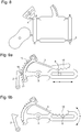
- a first embodiment of a watch mechanism according to the invention is represented in different positions on the Figures 1 to 5 .
- the mechanism of the invention is intended to be mounted on a watch movement, either in an integrated manner or in a modular manner.
- the mechanism aims to transform, on demand, an input value into an output value that varies in a similar or inverted way to the input value. It is for that reason likely to be in two states, an inverter state as represented on the Figures 1 and 2 and a follower state as represented on the figures 4 and 5 .
- the particular position of the mechanism represented in figure 3 is the one in which the mechanism is likely to change state.
- the mechanism comprises a diamond-shaped deformable structure ABCD, comprising four coplanar segments connected in pairs by their vertices pivotally.
- the ABCD diamond has an AD input segment adjacent to an AB output segment, both rotated around a pivot axis X perpendicular to the plane of the diamond and passing through a first vertex A which is common to the input and output segments AB and which is locked in translation in the plane of the diamond ABCD. This means that the vertex A remains fixed in contrast to the other three vertices that can move in the plane of the ABCD rhombus.
- the mechanism also comprises a lever 1 pivotally mounted about the pivot axis X, the lever 1 being kinematically connected in rotation, about the pivot axis X, to a second vertex C of the diamond, opposite to the first vertex A.
- the lever 1 comprises an oblong opening 12 extending in a radial direction with reference to the pivot axis X and at least partially housing a pin 8 pivotally connecting, by their apex, that is to say the second top C, the third DC and fourth CB segments of the diamond.
- the oblong opening 12 has a width substantially equal to the diameter of the pin 8 and constitutes a slide in which the pin 8 can slide. It is obvious that any equivalent slide link system can be used, for example the oblong opening and the pin can be replaced by two pins flanking a parallel segment.
- the mechanism also comprises a first locking member 2 in the form of a pivoting arm whose one end is provided with a notch 10 arranged to cooperate with the end of the lever 1.
- the first locking member 2 is able to move between a position locked, in which the notch 10 covers the end of the lever 1 so as to lock the lever 1 in rotation about the pivot axis X, and an unlocked position in which the first locking member 2 does not hinder the rotation of the lever 1.
- the mechanism also comprises a second locking member 3, pivoted in Y on the lever 1 and one end has a hook 9 adapted to cooperate with the pin 8 so as to lock the pin 8 in translation in the radial direction.
- the second locking member 3 is able to move between a locked position, in which the second vertex C is locked in translation in a radial direction with reference to the pivot axis X, and an unlocked position in which the second locking member 3 does not interfere with the radial displacement of the second vertex C.
- the mechanism further comprises a first return means not shown, tending to maintain the first locking member 2 against a control device 4, described below.
- the first return means is a resilient return means
- a desmodromic connection can be used between the control device 4 and the first locking member 2.
- a second biasing means tends to hold the second locking member 3 in its locked position as shown in FIG. Figures 3 to 6 .
- the action of the second return means allows the second locking member to lock the pin 8 in translation in the radial direction.
- the second return means may, for example, be an elastic means or a magnetic means.
- the mechanism is arranged so that there is always only one of the first and second locking members 2, 3 in the locked position, the other of the first and second locking members 2, 3 then being in position. unlocked position.
- the mechanism is in its inverter state when the first locking member is locked, and in its follower state when the second member is locked.
- the movements of the first 2 and second 3 locking members, corresponding to changes in the state of the mechanism are performed in a synchronized manner.
- the first locking member 2 comprises a stop 11 intended to cooperate with a lever arm 15 that comprises the second locking member 3, in order to move the second locking member 3 in its unlocked position when the first locking member 2 moves to its locked position.
- the second locking member 3 moves into its locked position under the action of the second return means.
- the mechanism also comprises the control device 4 which is able to control the displacement of the first locking member 2 between its locked and unlocked positions.
- the control device 4 is here made using a Maltese cross 13 rotated by an indexing finger 14 intended to be itself driven by the movement.
- the displacement of the first locking member 2 by the control device 4 occurs when the lever 1 and the pin 8 are in a particular position called permutation, as shown in FIG. figure 3 .
- the angular position of the input segment AD is governed by the displacement of a probe 5, integral with the input segment AD, and arranged to follow the profile of a cam 6 intended to be rotated by a watch movement.
- the input segment AD could also be integral with a sector gear able to receive the input value represented by the angular position of the input segment AD.
- the output segment AB is secured to a toothed sector 7 adapted to mesh with a toothed wheel or a rack to transmit the output value of the mechanism.
- the figure 6 represents a schematic diagram of the mechanism in its inverter state, the diagonal AC of the diamond ABCD being locked in rotation around the axis X.
- the angular position ⁇ of the input segment AD represents the input value of the mechanism whereas the output value is represented by the angular position ⁇ of the output segment AB.
- the permutation value p corresponds to values of 45 ° for the angles ⁇ and ⁇ , which means that the diamond ABCD is a square when the mechanism is in the follower state.
- the ABCD diamond rotates in one piece around the pivot axis X so that the output value varies similarly to the input value.
- the output value ⁇ is equal to the input value ⁇ .
- the output value ⁇ varies inversely with the input value ⁇ .
- the change of state occurs at the permutation value p which is not necessarily zero.
- the output value can be transmitted using gear sector 7 to another mechanism or display device.
- a display means such as a marker, integral with the output segment AB and able to indicate the output value represented by the angular position of the output segment AB.
- the permutation from one state to the other of the mechanism can only occur at the permutation value p in the configuration of the figure 3 , it is preferable that the control device 4 is synchronized with the displacement of the cam 6.
- the figure 7 gives an illustration of the inversion of a function by the inverting mechanism. The change of state occurs at a time t p .
- the left part of the graph corresponds to the follower state in which the input value ⁇ coincides with the output value ⁇ .
- the left part of the graph corresponds to the inverter state in which the output value ⁇ varies inversely with the input value ⁇ around the permutation value p.
- the ABCD diamond is integrally formed, each segment of the rhombus being connected to the adjacent segments by flexible elements acting as a pivot.
- the pivot axis X is also a virtual pivot axis formed by two deformable flexible arms connecting the input segment AD to a fixed base.
- the lever 1 and the first and second locking members 2, 3 can also be pivoted using virtual pivots.
- the present invention covers all combinations using physical pivots or virtual pivots.
- the Figures 9a and 9b present the lever 1 and the first and second locking members 2, 3 of a second embodiment of the invention. Unlike the first embodiment presented, the permutation value p is here variable.
- the figure 9a corresponds to the inverter state of the mechanism in which the first locking member 2 is in a locked position.
- the first locking member 2 comprises a tip 16 which is housed between two teeth of a toothing 17 secured to the lever 1. Upon penetrating the toothing 17, the tip 16 presses on a lever arm 15 that includes the second locking member 3 which holds it in an unlocked position in which the pin 8 is free to move radially with reference to the pivot axis X.
- the figure 9b corresponds to the follower state in which the second locking member 3 is in a locked position.
- the second locking member 3 comprises a rack 18 whose toothing cooperates with the pin 8 to lock it in translation when the first locking member 2 is placed in its unlocked position.
- the first 2 and second 3 locking members comprise a plurality of notches respectively hooks.
- the permutation value is variable.
- the adjustment can be made by the movement or by the user according to a suitable adjustment device.
- the values of permutations here take values varying in discrete steps but it is also possible to envisage a continuous variation by reducing the value of the pitch.
- the mechanism according to the invention makes it possible to selectively invert an input function. Many applications of this mechanism are conceivable.
- a retrograde display can alternate its movement.
- the reference means of the retrograde display can evolve together with the permutation.
- a pusher correction device can act in both directions of correction depending on the state in which one chooses to place the mechanism, the permutation being effected when the correction device is at rest.
- the present invention is not limited to the illustrated example and is susceptible of various variations and modifications which will become apparent to those skilled in the art.
- the roles of the segments AD and AB can be reversed, the segment AD then being an output segment and the segment AB being an input segment.
Landscapes
- Physics & Mathematics (AREA)
- General Physics & Mathematics (AREA)
- Geometry (AREA)
- Electric Clocks (AREA)
- Mechanical Control Devices (AREA)
- Transmission Devices (AREA)
Abstract
- un losange (ABCD) déformable, comportant quatre segments coplanaires reliés deux à deux par leurs sommets de façon pivotante, dont un segment d'entré (AD) adjacent à un segment de sortie (AB), tous deux pivotés autour d'un axe de pivot (X) perpendiculaire au plan du losange et passant par un premier sommet (A) commun aux segments d'entrée (AD) et de sortie (AB) et bloqué en translation dans le plan du losange (ABCD),
- un levier (1) monté pivotant autour de l'axe de pivot (X), le levier (1) étant cinématiquement lié en rotation, autour de l'axe de pivot (X), à un deuxième sommet (C) du losange, opposé au premier sommet (A),
- un premier organe de blocage (2) apte à se déplacer entre une position verrouillée, dans laquelle le levier (1) est bloqué en rotation autour de l'axe de pivot (X), et une position déverrouillée dans laquelle le premier organe de blocage (2) n'entrave pas la rotation du levier (1),
- un second organe de blocage (3) apte à se déplacer entre une position verrouillée, dans laquelle le deuxième sommet (C) est bloqué en translation selon une direction radiale en référence à l'axe de pivot (X), et une position déverrouillée dans laquelle le second organe de blocage (3) n'entrave pas le déplacement radial du deuxième sommet (C), le mécanisme étant agencé de manière à ce que l'un des organes de blocage (2, 3) se trouve en position verrouillée lorsque l'autre est en position déverrouillée,
- un dispositif de commande (4) apte à commander le déplacement du premier organe de blocage (2) entre ses positions verrouillée et déverrouillée.
Description
- La présente invention se rapporte au domaine de l'horlogerie. Elle concerne plus particulièrement un mécanisme d'horlogerie capable de réaliser une opération mathématique.
- On connait les inverseurs qui permettent de transformer automatiquement le mouvement rotatif bidirectionnel de la masse oscillante en un mouvement de rotation unidirectionnel destiné à l'armage du barillet. La présente invention se propose de présenter un mécanisme inverseur qui soit capable de transformer, à la demande, une fonction d'entrée en une fonction de sortie variant d'une façon similaire ou inversée à la fonction d'entrée. A cette fin, le mécanisme est apte à fournir une valeur de sortie égale ou opposée à une valeur d'entrée.
- De façon plus précise, l'invention concerne un mécanisme d'horlogerie comportant :
- un losange déformable, comportant quatre segments coplanaires reliés deux à deux par leurs sommets de façon pivotante, dont un segment d'entrée adjacent à un segment de sortie, tous deux pivotés autour d'un axe de pivot perpendiculaire au plan du losange et passant par un premier sommet qui est commun aux segments d'entrée et de sortie et qui est bloqué en translation dans le plan du losange,
- un levier monté pivotant autour de l'axe de pivot, le levier étant cinématiquement lié en rotation, autour de l'axe de pivot, à un deuxième sommet du losange, opposé au premier sommet,
- un premier organe de blocage apte à se déplacer entre une position verrouillée, dans laquelle le levier est bloqué en rotation autour de l'axe de pivot, et une position déverrouillée dans laquelle le premier organe de blocage n'entrave pas la rotation du levier,
- un second organe de blocage apte à se déplacer entre une position verrouillée, dans laquelle le deuxième sommet est bloqué en translation selon une direction radiale en référence à l'axe de pivot, et une position déverrouillée dans laquelle le second organe de blocage n'entrave pas le déplacement radial du deuxième sommet, le mécanisme étant agencé de manière à ce que l'un des premier et second organes de blocage se trouve en position verrouillée lorsque l'autre des premier et second organes de blocage est en position déverrouillée,
- un dispositif de commande apte à commander le déplacement du premier organe de blocage entre ses positions verrouillée et déverrouillée.
- Ainsi, la position angulaire du segment d'entrée représentant la valeur d'entrée du mécanisme, la position angulaire du segment de sortie représente une valeur de sortie variant similairement à la valeur d'entrée lorsque le premier organe de blocage est en position déverrouillée et variant à l'inverse de cette valeur lorsque le premier organe de blocage est en position verrouillée.
- Le mécanisme ainsi décrit permet de fournir, à la demande, une valeur de sortie égale ou opposée à une valeur d'entrée.
- Selon un aspect avantageux de l'invention, le mécanisme comporte un premier moyen de rappel tendant à maintenir le premier organe de blocage en appui contre le dispositif de commande.
- Selon un autre aspect avantageux de l'invention, le mécanisme comporte une liaison desmodromique entre le dispositif de commande et le premier organe de blocage.
- Selon un autre aspect avantageux, le mécanisme comporte un second moyen de rappel tendant à maintenir le second organe de blocage dans sa position verrouillée.
- Selon un autre aspect avantageux de l'invention, le premier organe de blocage est agencé pour déplacer le second organe de blocage dans sa position déverrouillée lorsque le premier organe de blocage se déplace dans sa position verrouillée.
- Selon un autre aspect avantageux de l'invention, le segment d'entrée est solidaire d'un palpeur agencé pour suivre le profil d'une came destinée à être entraînée en rotation par un mécanisme d'horlogerie commandé par un mouvement horloger ou par un utilisateur.
- Selon un autre aspect avantageux de l'invention, le segment de sortie est solidaire d'un secteur denté apte à transmettre la valeur de sortie représentée par la position angulaire du segment de sortie.
- Selon un autre aspect avantageux de l'invention, le levier comporte une ouverture oblongue s'étendant dans une direction radiale en référence à l'axe de pivot et logeant au moins partiellement une goupille connectant de façon pivotante par leur sommet, constitué par le deuxième sommet, les troisième et quatrième segments du losange.
- Selon un autre aspect avantageux de l'invention, le deuxième organe de blocage est pivoté sur le levier et comporte un crochet coopérant avec la goupille de façon à pouvoir bloquer la goupille en translation selon la direction radiale.
- Selon un autre aspect avantageux de l'invention, le premier organe de blocage est pivoté et comporte une encoche coopérant avec le levier de façon à pouvoir bloquer le levier en rotation autour de l'axe de pivot.
- D'autres détails de l'invention apparaîtront plus clairement à la lecture de la description qui suit, faite en référence aux dessins annexés dans lesquels :
- les
figures 1 à 5 représentent un premier mode de réalisation d'un mécanisme de l'invention dans différentes positions, - la
figure 6 représente une vue schématique du mécanisme dans l'état inverseur, - la
figure 7 représente un graphe de fonctions entrée et sortie du mécanisme, - la
figure 8 représente une variante d'exécution du premier mode de réalisation, et - les
figures 9a et 9b représentent le levier et les premier et deuxième organes de blocage d'un deuxième mode de réalisation de l'invention. - Un premier mode de réalisation d'un mécanisme d'horlogerie selon l'invention est représenté dans différentes positions sur les
figures 1 à 5 . Le mécanisme de l'invention est destiné à être monté sur un mouvement horloger, soit de façon intégrée, soit de façon modulaire. Le mécanisme a pour objectif de transformer, à la demande, une valeur d'entrée en une valeur de sortie variant d'une façon similaire ou inversée à la valeur d'entrée. Il est pour cela susceptible de se trouver dans deux états, un état inverseur tel que représenté sur lesfigures 1 et 2 et un état suiveur tel que représenté sur lesfigures 4 et5 . La position particulière du mécanisme représentée à lafigure 3 est celle dans laquelle le mécanisme est susceptible de changer d'état. - Le mécanisme comporte une structure déformable en forme de losange ABCD, comportant quatre segments coplanaires reliés deux à deux par leurs sommets de façon pivotante. Le losange ABCD comporte un segment d'entré AD adjacent à un segment de sortie AB, tous deux pivotés autour d'un axe de pivot X perpendiculaire au plan du losange et passant par un premier sommet A qui est commun aux segments d'entrée AD et de sortie AB et qui est bloqué en translation dans le plan du losange ABCD. Cela signifie que le sommet A reste fixe au contraire des trois autres sommets qui peuvent se déplacer dans le plan du losange ABCD.
- Le mécanisme comporte également un levier 1 monté pivotant autour de l'axe de pivot X, le levier 1 étant cinématiquement lié en rotation, autour de l'axe de pivot X, à un deuxième sommet C du losange, opposé au premier sommet A. Le levier 1 comporte une ouverture oblongue 12 s'étendant dans une direction radiale en référence à l'axe de pivot X et logeant au moins partiellement une goupille 8 connectant de façon pivotante, par leur sommet, c'est-à-dire le deuxième sommet C, les troisième DC et quatrième CB segments du losange. L'ouverture oblongue 12 a une largeur sensiblement égale au diamètre de la goupille 8 et constitue une glissière dans laquelle la goupille 8 peut coulisser. Il est bien évident que tout système de liaison glissière équivalent peut être utilisé, par exemple l'ouverture oblongue et la goupille peuvent être remplacées par deux goupilles encadrant un segment parallèle.
- Le mécanisme comporte également un premier organe de blocage 2 en forme de bras pivotant dont une extrémité est pourvue d'une encoche 10 agencée pour coopérer avec l'extrémité du levier 1. Le premier organe de blocage 2 est apte à se déplacer entre une position verrouillée, dans laquelle l'encoche 10 recouvre l'extrémité du levier 1 de façon à bloquer le levier 1 en rotation autour de l'axe de pivot X, et une position déverrouillée dans laquelle le premier organe de blocage 2 n'entrave pas la rotation du levier 1.
- Le mécanisme comporte également un second organe de blocage 3, pivoté en Y sur le levier 1 et dont une extrémité comporte un crochet 9 apte à coopérer avec la goupille 8 de façon à pouvoir bloquer la goupille 8 en translation selon la direction radiale. Le second organe de blocage 3 est apte à se déplacer entre une position verrouillée, dans laquelle le deuxième sommet C est bloqué en translation selon une direction radiale en référence à l'axe de pivot X, et une position déverrouillée dans laquelle le second organe de blocage 3 n'entrave pas le déplacement radial du deuxième sommet C.
- Le mécanisme comporte en outre un premier moyen de rappel non représenté, tendant à maintenir le premier organe de blocage 2 en appui contre un dispositif de commande 4, décrit ci-après. Typiquement, le premier moyen de rappel est un moyen de rappel élastique Alternativement à un moyen de rappel, une liaison desmodromique peut être utilisée entre le dispositif de commande 4 et le premier organe de blocage 2.
- Un second moyen de rappel, non représenté, tend à maintenir le second organe de blocage 3 dans sa position verrouillée telle que représentée au
figures 3 à 6 . L'action du second moyen de rappel permet au second organe de blocage de bloquer la goupille 8 en translation selon la direction radiale. Le second moyen de rappel peut, par exemple, être un moyen élastique ou un moyen magnétique. - Le mécanisme est agencé de manière à ce qu'il n'y ait toujours qu'un seul des premier et second organes de blocage 2, 3 en position verrouillée, l'autre des premier et second organes de blocage 2, 3 étant alors en position déverrouillée. Le mécanisme est dans son état inverseur lorsque le premier organe de blocage est verrouillé, et dans son état suiveur lorsque le second organe est verrouillé. Autrement dit, les déplacements des premier 2 et second 3 organes de blocage, correspondant à des changements d'état du mécanisme, s'effectuent de façon synchronisée. Pour cela, le premier organe de blocage 2 comporte une butée 11 destinée à coopérer avec un bras de levier 15 que comporte le second organe de blocage 3, afin de déplacer le second organe de blocage 3 dans sa position déverrouillée lorsque le premier organe de blocage 2 se déplace dans sa position verrouillée. Inversement, lorsque le premier organe de blocage 2 se déplace dans sa position déverrouillée, le second organe de blocage 3 se déplace dans sa position verrouillée sous l'action du second moyen de rappel.
- Le mécanisme comporte également le dispositif de commande 4 qui est apte à commander le déplacement du premier organe de blocage 2 entre ses positions verrouillée et déverrouillée. Le dispositif de commande 4 est ici réalisé à l'aide d'une croix de Malte 13 entrainée en rotation par un doigt d'indexation 14 destiné à être lui-même entrainé par le mouvement. Le déplacement du premier organe de blocage 2 par le dispositif de commande 4 intervient lorsque le levier 1 et la goupille 8 sont dans une position particulière dite de permutation, telle que représentée à la
figure 3 . - La position angulaire du segment d'entrée AD est régie par le déplacement d'un palpeur 5, solidaire du segment d'entrée AD, et agencé pour suivre le profil d'une came 6 destinée à être entraînée en rotation par un mouvement horloger. Alternativement, le segment d'entrée AD pourrait également être solidaire d'un secteur denté apte à recevoir la valeur d'entrée représentée par la position angulaire du segment d'entrée AD.
- Le segment de sortie AB est solidaire d'un secteur denté 7 apte à engrener avec une roue dentée ou une crémaillère pour transmettre la valeur de sortie du mécanisme.
- La
figure 6 représente un schéma de principe du mécanisme dans son état inverseur, la diagonale AC du losange ABCD étant bloquée en rotation autour de l'axe X. La position angulaire α du segment d'entrée AD, représente la valeur d'entrée du mécanisme alors que la valeur de sortie est représentée par la position angulaire β du segment de sortie AB. Dans le premier mode de réalisation représenté, la valeur de permutation p correspond à des valeurs de 45° pour les angles α et β ce qui signifie que le losange ABCD est un carré lorsque le mécanisme est dans l'état suiveur. - Lorsque le mécanisme est dans l'état suiveur, c'est-à-dire quand le premier organe de blocage 2 est en position déverrouillée, le losange ABCD pivote de façon monobloc autour de l'axe de pivot X de telle sorte que la valeur de sortie varie similairement à la valeur d'entrée. Avec les repères choisis pour la
figure 6 , la valeur de sortie β est égale à la valeur d'entrée α. - Lorsque le mécanisme est dans l'état inverseur représenté à la
figure 6 , c'est-à-dire quand le premier organe de blocage 2 est en position verrouillée, la valeur de sortie β varie à l'inverse de la valeur d'entrée α. Le changement d'état s'effectue à la valeur de permutation p qui n'est pas nécessairement nulle. La valeur de sortie s'exprime ainsi : β = 2p - α. Dans le cas particulier où la valeur de permutation p est nulle, la valeur de sortie β est l'opposée de la valeur d'entrée α. - La valeur de sortie peut être transmise à l'aide du secteur dentée 7 à destination d'un autre mécanisme ou d'un dispositif d'affichage. Alternativement, il est possible de prévoir un moyen d'affichage tel un repère, solidaire du segment de sortie AB et apte à indiquer la valeur de sortie représentée par la position angulaire du segment de sortie AB.
- Dans le premier mode de réalisation, la permutation d'un état à l'autre du mécanisme ne pouvant intervenir qu'à la valeur de permutation p dans la configuration de la
figure 3 , il est préférable que le dispositif de commande 4 soit synchronisé avec le déplacement de la came 6. Lafigure 7 donne une illustration de l'inversion d'une fonction par le mécanisme inverseur. Le changement d'état a lieu à un instant tp. La partie gauche du graphe correspond à l'état suiveur dans lequel la valeur d'entrée α est confondue avec la valeur de sortie β. La partie gauche du graphe correspond à l'état inverseur dans lequel la valeur de sortie β varie de manière inversée à la valeur d'entrée α autour de la valeur de permutation p. - Selon une variante d'exécution représentée à la
figure 8 , le losange ABCD est formé de façon monobloc, chaque segment du losange étant relié aux segments adjacents par des éléments flexibles faisant office de pivot. Dans cette variante, l'axe de pivot X est également un axe de pivot virtuel formé par deux bras flexibles déformables reliant le segment d'entrée AD à une base fixe. De la même façon, le levier 1 et les premier et deuxième organes de blocage 2, 3 peuvent également être pivotés à l'aide de pivots virtuels. La présente invention couvre toutes les combinaisons faisant appel à des pivots physiques ou des pivots virtuels. - Les
figures 9a et 9b présentent le levier 1 et les premier et deuxième organes 2, 3 de blocage d'un deuxième mode de réalisation de l'invention. Contrairement au premier mode de réalisation présenté, la valeur de permutation p est ici variable. - La
figure 9a correspond à l'état inverseur du mécanisme dans lequel le premier organe de blocage 2 est dans une position verrouillée. Le premier organe de blocage 2 comporte une pointe 16 se logeant entre deux dents d'une denture 17 solidaire du levier 1. En pénétrant dans la denture 17, la pointe 16 appuie sur un bras de levier 15 que comporte le second organe de blocage 3 ce qui le maintient dans une position déverrouillée dans laquelle la goupille 8 est libre de se déplacer radialement en référence à l'axe de pivot X. - La
figure 9b correspond à l'état suiveur dans lequel le second organe de blocage 3 est dans une position verrouillée. Le second organe de blocage 3 comporte une crémaillère 18 dont la denture coopère avec la goupille 8 pour la bloquer en translation lorsque le premier organe de blocage 2 est placé dans sa position déverrouillée. - Dans le deuxième mode de réalisation représenté sur les
figures 9a et 9b , les premier 2 et deuxième 3 organes de blocage comportent une pluralité d'encoches respectivement de crochets. Ainsi la valeur d'entrée à laquelle s'effectue le déplacement des organes de blocage 2, 3 entre leurs positions verrouillées et déverrouillées, dite valeur de permutation, est variable. Le réglage peut être fait par le mouvement ou par l'utilisateur selon un dispositif de réglage approprié. Les valeurs de permutations prennent ici des valeurs variant par pas discrets mais il est également possible d'envisager une variation continue en réduisant la valeur du pas. - Ainsi le mécanisme selon l'invention permet de réaliser l'inversion sélective d'une fonction d'entrée. De nombreuses applications de ce mécanisme sont envisageables.
- Un affichage rétrograde peut alterner son mouvement. Pour faciliter la lecture de l'information, les moyens de repère de l'affichage rétrograde peuvent évoluer conjointement à la permutation.
- Un dispositif de correction par poussoir peut agir dans les deux sens de correction en fonction de l'état dans lequel on choisit de placer le mécanisme, la permutation s'effectuant lorsque le dispositif de correction est au repos.
- La présente invention ne se limite pas à l'exemple illustré et est susceptible de diverses variantes et modifications qui apparaîtront de manière évidente à l'homme du métier. Ainsi par exemple, les rôles des segments AD et AB peuvent être inversés, le segment AD étant alors un segment de sortie et le segment AB étant un segment d'entrée.
Claims (14)
- Mécanisme d'horlogerie caractérisé en ce qu'il comporte :- un losange (ABCD) déformable, comportant quatre segments coplanaires reliés deux à deux par leurs sommets de façon pivotante, dont un segment d'entré (AD) adjacent à un segment de sortie (AB), tous deux pivotés autour d'un axe de pivot (X) perpendiculaire au plan du losange et passant par un premier sommet (A) qui est commun aux segments d'entrée (AD) et de sortie (AB) et qui est bloqué en translation dans le plan du losange (ABCD),- un levier (1) monté pivotant autour de l'axe de pivot (X), le levier (1) étant cinématiquement lié en rotation, autour de l'axe de pivot (X), à un deuxième sommet (C) du losange, opposé au premier sommet (A),- un premier organe de blocage (2) apte à se déplacer entre une position verrouillée, dans laquelle le levier (1) est bloqué en rotation autour de l'axe de pivot (X), et une position déverrouillée dans laquelle le premier organe de blocage (2) n'entrave pas la rotation du levier (1),- un second organe de blocage (3) apte à se déplacer entre une position verrouillée, dans laquelle le deuxième sommet (C) est bloqué en translation selon une direction radiale en référence à l'axe de pivot (X), et une position déverrouillée dans laquelle le second organe de blocage (3) n'entrave pas le déplacement radial du deuxième sommet (C), le mécanisme étant agencé de manière à ce que l'un des premier et second organes de blocage (2, 3) se trouve en position verrouillée lorsque l'autre des premier et second organes de blocage (2, 3) est en position déverrouillée,- un dispositif de commande (4) apte à commander le déplacement du premier organe de blocage (2) entre ses positions verrouillée et déverrouillée,et en ce que la position angulaire du segment de sortie (AB) représente une valeur de sortie variant similairement à une valeur d'entrée lorsque le premier organe de blocage (2) est en position déverrouillée et variant à l'inverse de cette valeur lorsque le premier organe de blocage (2) est en position verrouillée, la valeur d'entrée étant représentée par la position angulaire du segment d'entrée (AD).
- Mécanisme selon la revendication 1, caractérisée en ce qu'il comporte un premier moyen de rappel tendant à maintenir le premier organe de blocage (2) en appui contre le dispositif de commande (4).
- Mécanisme selon la revendication 1, caractérisé en ce qu'il comporte une liaison desmodromique entre le dispositif de commande (4) et le premier organe de blocage (2).
- Mécanisme selon l'une des revendications précédentes, caractérisée en ce qu'il comporte un second moyen de rappel tendant à maintenir le second organe de blocage (3) dans sa position verrouillée.
- Mécanisme selon l'une des revendications précédentes, caractérisée en ce que le premier organe de blocage (2) est agencé pour déplacer le second organe de blocage (3) dans sa position déverrouillée lorsque le premier organe de blocage (2) se déplace dans sa position verrouillée.
- Mécanisme selon l'une des revendications précédentes, caractérisée en ce que le segment d'entrée (AD) est solidaire d'un palpeur (5) agencé pour suivre le profil d'une came (6) destinée à être entraînée en rotation par un mouvement horloger ou par un utilisateur.
- Mécanisme selon l'une des revendications 1 à 5, caractérisée en ce que le segment d'entrée (AD) est solidaire d'un secteur denté apte à recevoir la valeur d'entrée représentée par la position angulaire du segment d'entrée (AD).
- Mécanisme selon l'une des revendications précédentes, caractérisée en ce que le segment de sortie (AB) est solidaire d'un secteur denté (7) apte à transmettre la valeur de sortie représentée par la position angulaire du segment de sortie (AB).
- Mécanisme selon l'une des revendications 1 à 7, caractérisée en ce qu'il comporte un repère solidaire du segment de sortie (AB) et apte à indiquer la valeur de sortie représentée par la position angulaire du segment de sortie (AB).
- Mécanisme selon l'une des revendications précédentes, caractérisée en ce que le levier (1) comporte une ouverture oblongue (12) s'étendant dans une direction radiale en référence à l'axe de pivot (X) et logeant au moins partiellement une goupille (8) connectant de façon pivotante par leur sommet, constitué par le deuxième sommet (C), les troisième (DC) et quatrième (CB) segments du losange.
- Mécanisme selon l'une des revendications précédentes, caractérisée en ce que le deuxième organe de blocage (3) est pivoté sur le levier (1) et comporte un crochet (9) coopérant avec la goupille (8) de façon à pouvoir bloquer la goupille (8) en translation selon la direction radiale.
- Mécanisme selon l'une des revendications précédentes, caractérisée en ce que le premier organe de blocage (2) est pivoté et comporte une encoche (10) coopérant avec le levier (1) de façon à pouvoir bloquer le levier (1) en rotation autour de l'axe de pivot. (X)
- Mécanisme selon les revendications 11 et 12, caractérisée en ce que les premier (2) et deuxième (3) organes de blocage comportent une pluralité d'encoches respectivement de crochets.
- Mécanisme selon l'une des revendications précédentes, caractérisé en ce que la valeur d'entrée à laquelle s'effectue le déplacement des organes de blocage (2, 3) entre leur position verrouillée et déverrouillée est variable.
Priority Applications (4)
| Application Number | Priority Date | Filing Date | Title |
|---|---|---|---|
| EP17173324.9A EP3410231B1 (fr) | 2017-05-29 | 2017-05-29 | Mécanisme d'horlogerie |
| US15/972,285 US10606215B2 (en) | 2017-05-29 | 2018-05-07 | Timepiece mechanism |
| JP2018097677A JP6533851B2 (ja) | 2017-05-29 | 2018-05-22 | 計時器用機構 |
| CN201810520986.3A CN108931911B (zh) | 2017-05-29 | 2018-05-28 | 钟表机构 |
Applications Claiming Priority (1)
| Application Number | Priority Date | Filing Date | Title |
|---|---|---|---|
| EP17173324.9A EP3410231B1 (fr) | 2017-05-29 | 2017-05-29 | Mécanisme d'horlogerie |
Publications (2)
| Publication Number | Publication Date |
|---|---|
| EP3410231A1 true EP3410231A1 (fr) | 2018-12-05 |
| EP3410231B1 EP3410231B1 (fr) | 2021-06-30 |
Family
ID=59009527
Family Applications (1)
| Application Number | Title | Priority Date | Filing Date |
|---|---|---|---|
| EP17173324.9A Active EP3410231B1 (fr) | 2017-05-29 | 2017-05-29 | Mécanisme d'horlogerie |
Country Status (4)
| Country | Link |
|---|---|
| US (1) | US10606215B2 (fr) |
| EP (1) | EP3410231B1 (fr) |
| JP (1) | JP6533851B2 (fr) |
| CN (1) | CN108931911B (fr) |
Cited By (1)
| Publication number | Priority date | Publication date | Assignee | Title |
|---|---|---|---|---|
| EP4650884A1 (fr) * | 2024-05-16 | 2025-11-19 | Patek Philippe Sa Geneve | Mécanisme d'entraînement pour affichage sautant |
Families Citing this family (6)
| Publication number | Priority date | Publication date | Assignee | Title |
|---|---|---|---|---|
| EP3486735B1 (fr) * | 2017-11-20 | 2020-09-30 | Montres Breguet S.A. | Mécanisme horloger de remise à zéro de la seconde à came en colimaçon |
| EP3605243A1 (fr) * | 2018-07-31 | 2020-02-05 | Montres Breguet S.A. | Mecanisme d'affichage d'horlogerie a geometrie variable avec aiguille elastique |
| EP3869280B1 (fr) * | 2020-02-19 | 2024-04-17 | Montres Breguet S.A. | Mecanisme d'affichage d'horlogerie |
| EP4336274B1 (fr) * | 2022-09-08 | 2025-05-28 | Montres Breguet S.A. | Mecanisme d'actionnement pour une aiguille d'affichage flexible |
| EP4538804A1 (fr) * | 2023-10-10 | 2025-04-16 | Montres Breguet S.A. | Composant d'un mouvement horloger comportant une articulation apte à être verrouillée |
| CH721553A1 (fr) * | 2024-01-26 | 2025-07-31 | Richemont Int Sa | Dispositif d'affichage pour mouvement horloger |
Citations (1)
| Publication number | Priority date | Publication date | Assignee | Title |
|---|---|---|---|---|
| CH694175A5 (fr) * | 1999-12-16 | 2004-08-13 | Agenhor Sa | Affichage rétrograde. |
Family Cites Families (8)
| Publication number | Priority date | Publication date | Assignee | Title |
|---|---|---|---|---|
| JPS5335499Y2 (fr) * | 1974-01-23 | 1978-08-30 | ||
| USD357883S (en) * | 1994-03-08 | 1995-05-02 | Krauss Kenneth W | Clock hand |
| EP1637942A1 (fr) * | 2004-09-15 | 2006-03-22 | Frédéric Piguet S.A. | Pièce d'horlogerie à quantième comprenant un dispositif d'équation du temps marchante |
| EP1777598B1 (fr) * | 2005-10-21 | 2012-02-15 | Rolex Sa | Pièce d'horlogerie munie d'un mécanisme de mesure de durées prédéterminées réglables |
| RU2592776C2 (ru) * | 2012-02-27 | 2016-07-27 | Бланпэн Са | Универсальный подвижный механизм уравнения времени и способ его установки |
| EP2824521B1 (fr) * | 2013-07-12 | 2025-03-26 | Rolex Sa | Mécanisme horloger, mouvement horloger et pièce d'horlogerie |
| CH713069A2 (fr) * | 2016-10-25 | 2018-04-30 | Eta Sa Mft Horlogere Suisse | Montre mécanique avec résonateur rotatif isochrone, insensible aux positions. |
| EP3410232B1 (fr) * | 2017-05-29 | 2021-07-21 | Montres Breguet S.A. | Mécanisme d'horlogerie |
-
2017
- 2017-05-29 EP EP17173324.9A patent/EP3410231B1/fr active Active
-
2018
- 2018-05-07 US US15/972,285 patent/US10606215B2/en active Active
- 2018-05-22 JP JP2018097677A patent/JP6533851B2/ja active Active
- 2018-05-28 CN CN201810520986.3A patent/CN108931911B/zh active Active
Patent Citations (1)
| Publication number | Priority date | Publication date | Assignee | Title |
|---|---|---|---|---|
| CH694175A5 (fr) * | 1999-12-16 | 2004-08-13 | Agenhor Sa | Affichage rétrograde. |
Cited By (1)
| Publication number | Priority date | Publication date | Assignee | Title |
|---|---|---|---|---|
| EP4650884A1 (fr) * | 2024-05-16 | 2025-11-19 | Patek Philippe Sa Geneve | Mécanisme d'entraînement pour affichage sautant |
Also Published As
| Publication number | Publication date |
|---|---|
| JP2018200312A (ja) | 2018-12-20 |
| US10606215B2 (en) | 2020-03-31 |
| CN108931911B (zh) | 2020-06-19 |
| EP3410231B1 (fr) | 2021-06-30 |
| CN108931911A (zh) | 2018-12-04 |
| US20180341224A1 (en) | 2018-11-29 |
| JP6533851B2 (ja) | 2019-06-19 |
Similar Documents
| Publication | Publication Date | Title |
|---|---|---|
| EP3410231B1 (fr) | Mécanisme d'horlogerie | |
| EP2984526B1 (fr) | Mecanisme de selection et d'actionnement des fonctions d'un mouvement horloger | |
| EP2945026B1 (fr) | Mécanisme de correction rapide d'horlogerie | |
| EP3602202B1 (fr) | Dispositif de réglage de fonctions d'une pièce d'horlogerie | |
| CH711749A1 (fr) | Mécanisme de calendrier pour pièce d'horlogerie. | |
| CH702803B1 (fr) | Mécanisme de correction d'au moins deux informations affichées autres que l'heure courante, pour mouvement horloger. | |
| EP3629102B1 (fr) | Mécanisme d'affichage à guichet unique | |
| EP1684133A2 (fr) | Mouvement d'horlogerie | |
| CH713820A2 (fr) | Mécanisme d'horlogerie capable de réaliser une opération mathématique. | |
| EP2884345B1 (fr) | Sautoir pour mouvement d'horlogerie | |
| EP4270114A1 (fr) | Dispositif de selection et de commande de fonctions d'un mouvement horloger | |
| CH718458A1 (fr) | Mécanisme d'actionnement pour mouvement horloger, en particulier mécanisme de chronographe comportant un tel mécanisme d'actionnement. | |
| CH708338A2 (fr) | Mécanisme correcteur pas-à-pas. | |
| WO2010026216A1 (fr) | Mecanisme d'affichage d'une information periodique | |
| CH713117B1 (fr) | Boîte de montre à lunette tournante verrouillable. | |
| FR2973122A1 (fr) | Mecanisme d'actionnement pour mouvement horloger et mouvement horloger correspondant | |
| EP2765463B1 (fr) | Mécanisme de transmission de mouvements axiaux et rotatifs entre deux axes décalés et pièce d'horlogerie comportant ce mécanisme | |
| CH720212B1 (fr) | Mouvement horloger comprenant un module de liaison cinématique interposé entre un dispositif de sélection et de commande de fonctions et un dispositif d'affichage | |
| EP3913443B1 (fr) | Dispositif de commande pour mécanismes horlogers | |
| EP4462192B1 (fr) | Dispositif d'affichage pour mouvement horloger | |
| CH708741A2 (fr) | Dispositif correcteur pour pièce d'horlogerie. | |
| EP1791038A1 (fr) | Mouvement horloger | |
| CH715152A1 (fr) | Mécanisme d'affichage du quantième de type grande date. | |
| EP4571427A1 (fr) | Dispositif de sélection et d'actionnement d'au moins deux fonctions d'un mouvement d'horlogerie | |
| CH720984B1 (fr) | Mécanisme de commande pour pièce d'horlogerie |
Legal Events
| Date | Code | Title | Description |
|---|---|---|---|
| PUAI | Public reference made under article 153(3) epc to a published international application that has entered the european phase |
Free format text: ORIGINAL CODE: 0009012 |
|
| STAA | Information on the status of an ep patent application or granted ep patent |
Free format text: STATUS: THE APPLICATION HAS BEEN PUBLISHED |
|
| AK | Designated contracting states |
Kind code of ref document: A1 Designated state(s): AL AT BE BG CH CY CZ DE DK EE ES FI FR GB GR HR HU IE IS IT LI LT LU LV MC MK MT NL NO PL PT RO RS SE SI SK SM TR |
|
| AX | Request for extension of the european patent |
Extension state: BA ME |
|
| STAA | Information on the status of an ep patent application or granted ep patent |
Free format text: STATUS: REQUEST FOR EXAMINATION WAS MADE |
|
| 17P | Request for examination filed |
Effective date: 20190605 |
|
| RBV | Designated contracting states (corrected) |
Designated state(s): AL AT BE BG CH CY CZ DE DK EE ES FI FR GB GR HR HU IE IS IT LI LT LU LV MC MK MT NL NO PL PT RO RS SE SI SK SM TR |
|
| RIC1 | Information provided on ipc code assigned before grant |
Ipc: G04B 19/08 20060101ALI20201223BHEP Ipc: G04B 19/02 20060101AFI20201223BHEP Ipc: G04B 13/00 20060101ALI20201223BHEP Ipc: G04B 27/00 20060101ALI20201223BHEP |
|
| GRAP | Despatch of communication of intention to grant a patent |
Free format text: ORIGINAL CODE: EPIDOSNIGR1 |
|
| STAA | Information on the status of an ep patent application or granted ep patent |
Free format text: STATUS: GRANT OF PATENT IS INTENDED |
|
| INTG | Intention to grant announced |
Effective date: 20210202 |
|
| GRAS | Grant fee paid |
Free format text: ORIGINAL CODE: EPIDOSNIGR3 |
|
| GRAA | (expected) grant |
Free format text: ORIGINAL CODE: 0009210 |
|
| STAA | Information on the status of an ep patent application or granted ep patent |
Free format text: STATUS: THE PATENT HAS BEEN GRANTED |
|
| AK | Designated contracting states |
Kind code of ref document: B1 Designated state(s): AL AT BE BG CH CY CZ DE DK EE ES FI FR GB GR HR HU IE IS IT LI LT LU LV MC MK MT NL NO PL PT RO RS SE SI SK SM TR |
|
| REG | Reference to a national code |
Ref country code: CH Ref legal event code: EP |
|
| REG | Reference to a national code |
Ref country code: AT Ref legal event code: REF Ref document number: 1406901 Country of ref document: AT Kind code of ref document: T Effective date: 20210715 |
|
| REG | Reference to a national code |
Ref country code: DE Ref legal event code: R096 Ref document number: 602017041111 Country of ref document: DE |
|
| REG | Reference to a national code |
Ref country code: IE Ref legal event code: FG4D Free format text: LANGUAGE OF EP DOCUMENT: FRENCH |
|
| REG | Reference to a national code |
Ref country code: LT Ref legal event code: MG9D |
|
| PG25 | Lapsed in a contracting state [announced via postgrant information from national office to epo] |
Ref country code: FI Free format text: LAPSE BECAUSE OF FAILURE TO SUBMIT A TRANSLATION OF THE DESCRIPTION OR TO PAY THE FEE WITHIN THE PRESCRIBED TIME-LIMIT Effective date: 20210630 Ref country code: HR Free format text: LAPSE BECAUSE OF FAILURE TO SUBMIT A TRANSLATION OF THE DESCRIPTION OR TO PAY THE FEE WITHIN THE PRESCRIBED TIME-LIMIT Effective date: 20210630 Ref country code: BG Free format text: LAPSE BECAUSE OF FAILURE TO SUBMIT A TRANSLATION OF THE DESCRIPTION OR TO PAY THE FEE WITHIN THE PRESCRIBED TIME-LIMIT Effective date: 20210930 |
|
| REG | Reference to a national code |
Ref country code: NL Ref legal event code: MP Effective date: 20210630 |
|
| REG | Reference to a national code |
Ref country code: AT Ref legal event code: MK05 Ref document number: 1406901 Country of ref document: AT Kind code of ref document: T Effective date: 20210630 |
|
| PG25 | Lapsed in a contracting state [announced via postgrant information from national office to epo] |
Ref country code: LV Free format text: LAPSE BECAUSE OF FAILURE TO SUBMIT A TRANSLATION OF THE DESCRIPTION OR TO PAY THE FEE WITHIN THE PRESCRIBED TIME-LIMIT Effective date: 20210630 Ref country code: GR Free format text: LAPSE BECAUSE OF FAILURE TO SUBMIT A TRANSLATION OF THE DESCRIPTION OR TO PAY THE FEE WITHIN THE PRESCRIBED TIME-LIMIT Effective date: 20211001 Ref country code: NO Free format text: LAPSE BECAUSE OF FAILURE TO SUBMIT A TRANSLATION OF THE DESCRIPTION OR TO PAY THE FEE WITHIN THE PRESCRIBED TIME-LIMIT Effective date: 20210930 Ref country code: SE Free format text: LAPSE BECAUSE OF FAILURE TO SUBMIT A TRANSLATION OF THE DESCRIPTION OR TO PAY THE FEE WITHIN THE PRESCRIBED TIME-LIMIT Effective date: 20210630 Ref country code: RS Free format text: LAPSE BECAUSE OF FAILURE TO SUBMIT A TRANSLATION OF THE DESCRIPTION OR TO PAY THE FEE WITHIN THE PRESCRIBED TIME-LIMIT Effective date: 20210630 |
|
| PG25 | Lapsed in a contracting state [announced via postgrant information from national office to epo] |
Ref country code: EE Free format text: LAPSE BECAUSE OF FAILURE TO SUBMIT A TRANSLATION OF THE DESCRIPTION OR TO PAY THE FEE WITHIN THE PRESCRIBED TIME-LIMIT Effective date: 20210630 Ref country code: CZ Free format text: LAPSE BECAUSE OF FAILURE TO SUBMIT A TRANSLATION OF THE DESCRIPTION OR TO PAY THE FEE WITHIN THE PRESCRIBED TIME-LIMIT Effective date: 20210630 Ref country code: AT Free format text: LAPSE BECAUSE OF FAILURE TO SUBMIT A TRANSLATION OF THE DESCRIPTION OR TO PAY THE FEE WITHIN THE PRESCRIBED TIME-LIMIT Effective date: 20210630 Ref country code: ES Free format text: LAPSE BECAUSE OF FAILURE TO SUBMIT A TRANSLATION OF THE DESCRIPTION OR TO PAY THE FEE WITHIN THE PRESCRIBED TIME-LIMIT Effective date: 20210630 Ref country code: PT Free format text: LAPSE BECAUSE OF FAILURE TO SUBMIT A TRANSLATION OF THE DESCRIPTION OR TO PAY THE FEE WITHIN THE PRESCRIBED TIME-LIMIT Effective date: 20211102 Ref country code: NL Free format text: LAPSE BECAUSE OF FAILURE TO SUBMIT A TRANSLATION OF THE DESCRIPTION OR TO PAY THE FEE WITHIN THE PRESCRIBED TIME-LIMIT Effective date: 20210630 Ref country code: RO Free format text: LAPSE BECAUSE OF FAILURE TO SUBMIT A TRANSLATION OF THE DESCRIPTION OR TO PAY THE FEE WITHIN THE PRESCRIBED TIME-LIMIT Effective date: 20210630 Ref country code: SM Free format text: LAPSE BECAUSE OF FAILURE TO SUBMIT A TRANSLATION OF THE DESCRIPTION OR TO PAY THE FEE WITHIN THE PRESCRIBED TIME-LIMIT Effective date: 20210630 Ref country code: SK Free format text: LAPSE BECAUSE OF FAILURE TO SUBMIT A TRANSLATION OF THE DESCRIPTION OR TO PAY THE FEE WITHIN THE PRESCRIBED TIME-LIMIT Effective date: 20210630 |
|
| PG25 | Lapsed in a contracting state [announced via postgrant information from national office to epo] |
Ref country code: PL Free format text: LAPSE BECAUSE OF FAILURE TO SUBMIT A TRANSLATION OF THE DESCRIPTION OR TO PAY THE FEE WITHIN THE PRESCRIBED TIME-LIMIT Effective date: 20210630 |
|
| REG | Reference to a national code |
Ref country code: DE Ref legal event code: R097 Ref document number: 602017041111 Country of ref document: DE |
|
| PG25 | Lapsed in a contracting state [announced via postgrant information from national office to epo] |
Ref country code: DK Free format text: LAPSE BECAUSE OF FAILURE TO SUBMIT A TRANSLATION OF THE DESCRIPTION OR TO PAY THE FEE WITHIN THE PRESCRIBED TIME-LIMIT Effective date: 20210630 |
|
| PLBE | No opposition filed within time limit |
Free format text: ORIGINAL CODE: 0009261 |
|
| STAA | Information on the status of an ep patent application or granted ep patent |
Free format text: STATUS: NO OPPOSITION FILED WITHIN TIME LIMIT |
|
| PG25 | Lapsed in a contracting state [announced via postgrant information from national office to epo] |
Ref country code: AL Free format text: LAPSE BECAUSE OF FAILURE TO SUBMIT A TRANSLATION OF THE DESCRIPTION OR TO PAY THE FEE WITHIN THE PRESCRIBED TIME-LIMIT Effective date: 20210630 |
|
| 26N | No opposition filed |
Effective date: 20220331 |
|
| PG25 | Lapsed in a contracting state [announced via postgrant information from national office to epo] |
Ref country code: IT Free format text: LAPSE BECAUSE OF FAILURE TO SUBMIT A TRANSLATION OF THE DESCRIPTION OR TO PAY THE FEE WITHIN THE PRESCRIBED TIME-LIMIT Effective date: 20210630 |
|
| REG | Reference to a national code |
Ref country code: BE Ref legal event code: MM Effective date: 20220531 |
|
| PG25 | Lapsed in a contracting state [announced via postgrant information from national office to epo] |
Ref country code: MC Free format text: LAPSE BECAUSE OF FAILURE TO SUBMIT A TRANSLATION OF THE DESCRIPTION OR TO PAY THE FEE WITHIN THE PRESCRIBED TIME-LIMIT Effective date: 20210630 Ref country code: LU Free format text: LAPSE BECAUSE OF NON-PAYMENT OF DUE FEES Effective date: 20220529 |
|
| PG25 | Lapsed in a contracting state [announced via postgrant information from national office to epo] |
Ref country code: LT Free format text: LAPSE BECAUSE OF FAILURE TO SUBMIT A TRANSLATION OF THE DESCRIPTION OR TO PAY THE FEE WITHIN THE PRESCRIBED TIME-LIMIT Effective date: 20210630 Ref country code: IE Free format text: LAPSE BECAUSE OF NON-PAYMENT OF DUE FEES Effective date: 20220529 |
|
| PG25 | Lapsed in a contracting state [announced via postgrant information from national office to epo] |
Ref country code: BE Free format text: LAPSE BECAUSE OF NON-PAYMENT OF DUE FEES Effective date: 20220531 |
|
| P01 | Opt-out of the competence of the unified patent court (upc) registered |
Effective date: 20230611 |
|
| PG25 | Lapsed in a contracting state [announced via postgrant information from national office to epo] |
Ref country code: HU Free format text: LAPSE BECAUSE OF FAILURE TO SUBMIT A TRANSLATION OF THE DESCRIPTION OR TO PAY THE FEE WITHIN THE PRESCRIBED TIME-LIMIT; INVALID AB INITIO Effective date: 20170529 |
|
| PG25 | Lapsed in a contracting state [announced via postgrant information from national office to epo] |
Ref country code: MK Free format text: LAPSE BECAUSE OF FAILURE TO SUBMIT A TRANSLATION OF THE DESCRIPTION OR TO PAY THE FEE WITHIN THE PRESCRIBED TIME-LIMIT Effective date: 20210630 Ref country code: CY Free format text: LAPSE BECAUSE OF FAILURE TO SUBMIT A TRANSLATION OF THE DESCRIPTION OR TO PAY THE FEE WITHIN THE PRESCRIBED TIME-LIMIT Effective date: 20210630 |
|
| PG25 | Lapsed in a contracting state [announced via postgrant information from national office to epo] |
Ref country code: TR Free format text: LAPSE BECAUSE OF FAILURE TO SUBMIT A TRANSLATION OF THE DESCRIPTION OR TO PAY THE FEE WITHIN THE PRESCRIBED TIME-LIMIT Effective date: 20210630 |
|
| PG25 | Lapsed in a contracting state [announced via postgrant information from national office to epo] |
Ref country code: MT Free format text: LAPSE BECAUSE OF FAILURE TO SUBMIT A TRANSLATION OF THE DESCRIPTION OR TO PAY THE FEE WITHIN THE PRESCRIBED TIME-LIMIT Effective date: 20210630 |
|
| PGFP | Annual fee paid to national office [announced via postgrant information from national office to epo] |
Ref country code: DE Payment date: 20250423 Year of fee payment: 9 |
|
| PGFP | Annual fee paid to national office [announced via postgrant information from national office to epo] |
Ref country code: GB Payment date: 20250423 Year of fee payment: 9 |
|
| PGFP | Annual fee paid to national office [announced via postgrant information from national office to epo] |
Ref country code: FR Payment date: 20250423 Year of fee payment: 9 |
|
| PGFP | Annual fee paid to national office [announced via postgrant information from national office to epo] |
Ref country code: CH Payment date: 20250601 Year of fee payment: 9 |