EP3410178A1 - Method, device and computer program for virtual adapting of a spectacle frame - Google Patents
Method, device and computer program for virtual adapting of a spectacle frame Download PDFInfo
- Publication number
- EP3410178A1 EP3410178A1 EP17173929.5A EP17173929A EP3410178A1 EP 3410178 A1 EP3410178 A1 EP 3410178A1 EP 17173929 A EP17173929 A EP 17173929A EP 3410178 A1 EP3410178 A1 EP 3410178A1
- Authority
- EP
- European Patent Office
- Prior art keywords
- head
- frame
- metadata
- spectacle frame
- model
- Prior art date
- Legal status (The legal status is an assumption and is not a legal conclusion. Google has not performed a legal analysis and makes no representation as to the accuracy of the status listed.)
- Pending
Links
Images


Classifications
-
- G—PHYSICS
- G02—OPTICS
- G02C—SPECTACLES; SUNGLASSES OR GOGGLES INSOFAR AS THEY HAVE THE SAME FEATURES AS SPECTACLES; CONTACT LENSES
- G02C13/00—Assembling; Repairing; Cleaning
- G02C13/003—Measuring during assembly or fitting of spectacles
-
- G—PHYSICS
- G02—OPTICS
- G02C—SPECTACLES; SUNGLASSES OR GOGGLES INSOFAR AS THEY HAVE THE SAME FEATURES AS SPECTACLES; CONTACT LENSES
- G02C7/00—Optical parts
- G02C7/02—Lenses; Lens systems ; Methods of designing lenses
- G02C7/024—Methods of designing ophthalmic lenses
- G02C7/027—Methods of designing ophthalmic lenses considering wearer's parameters
-
- A—HUMAN NECESSITIES
- A61—MEDICAL OR VETERINARY SCIENCE; HYGIENE
- A61B—DIAGNOSIS; SURGERY; IDENTIFICATION
- A61B5/00—Measuring for diagnostic purposes; Identification of persons
- A61B5/103—Detecting, measuring or recording devices for testing the shape, pattern, colour, size or movement of the body or parts thereof, for diagnostic purposes
- A61B5/107—Measuring physical dimensions, e.g. size of the entire body or parts thereof
- A61B5/1079—Measuring physical dimensions, e.g. size of the entire body or parts thereof using optical or photographic means
-
- G—PHYSICS
- G02—OPTICS
- G02C—SPECTACLES; SUNGLASSES OR GOGGLES INSOFAR AS THEY HAVE THE SAME FEATURES AS SPECTACLES; CONTACT LENSES
- G02C7/00—Optical parts
- G02C7/02—Lenses; Lens systems ; Methods of designing lenses
- G02C7/024—Methods of designing ophthalmic lenses
- G02C7/028—Special mathematical design techniques
-
- G—PHYSICS
- G06—COMPUTING; CALCULATING OR COUNTING
- G06F—ELECTRIC DIGITAL DATA PROCESSING
- G06F30/00—Computer-aided design [CAD]
- G06F30/10—Geometric CAD
- G06F30/17—Mechanical parametric or variational design
-
- G—PHYSICS
- G06—COMPUTING; CALCULATING OR COUNTING
- G06F—ELECTRIC DIGITAL DATA PROCESSING
- G06F30/00—Computer-aided design [CAD]
- G06F30/20—Design optimisation, verification or simulation
- G06F30/27—Design optimisation, verification or simulation using machine learning, e.g. artificial intelligence, neural networks, support vector machines [SVM] or training a model
-
- G—PHYSICS
- G06—COMPUTING; CALCULATING OR COUNTING
- G06Q—INFORMATION AND COMMUNICATION TECHNOLOGY [ICT] SPECIALLY ADAPTED FOR ADMINISTRATIVE, COMMERCIAL, FINANCIAL, MANAGERIAL OR SUPERVISORY PURPOSES; SYSTEMS OR METHODS SPECIALLY ADAPTED FOR ADMINISTRATIVE, COMMERCIAL, FINANCIAL, MANAGERIAL OR SUPERVISORY PURPOSES, NOT OTHERWISE PROVIDED FOR
- G06Q30/00—Commerce
- G06Q30/06—Buying, selling or leasing transactions
- G06Q30/0601—Electronic shopping [e-shopping]
- G06Q30/0621—Item configuration or customization
-
- G—PHYSICS
- G06—COMPUTING; CALCULATING OR COUNTING
- G06T—IMAGE DATA PROCESSING OR GENERATION, IN GENERAL
- G06T19/00—Manipulating 3D models or images for computer graphics
- G06T19/20—Editing of 3D images, e.g. changing shapes or colours, aligning objects or positioning parts
-
- G—PHYSICS
- G06—COMPUTING; CALCULATING OR COUNTING
- G06T—IMAGE DATA PROCESSING OR GENERATION, IN GENERAL
- G06T7/00—Image analysis
- G06T7/30—Determination of transform parameters for the alignment of images, i.e. image registration
- G06T7/33—Determination of transform parameters for the alignment of images, i.e. image registration using feature-based methods
-
- G—PHYSICS
- G16—INFORMATION AND COMMUNICATION TECHNOLOGY [ICT] SPECIALLY ADAPTED FOR SPECIFIC APPLICATION FIELDS
- G16H—HEALTHCARE INFORMATICS, i.e. INFORMATION AND COMMUNICATION TECHNOLOGY [ICT] SPECIALLY ADAPTED FOR THE HANDLING OR PROCESSING OF MEDICAL OR HEALTHCARE DATA
- G16H20/00—ICT specially adapted for therapies or health-improving plans, e.g. for handling prescriptions, for steering therapy or for monitoring patient compliance
- G16H20/40—ICT specially adapted for therapies or health-improving plans, e.g. for handling prescriptions, for steering therapy or for monitoring patient compliance relating to mechanical, radiation or invasive therapies, e.g. surgery, laser therapy, dialysis or acupuncture
-
- G—PHYSICS
- G16—INFORMATION AND COMMUNICATION TECHNOLOGY [ICT] SPECIALLY ADAPTED FOR SPECIFIC APPLICATION FIELDS
- G16H—HEALTHCARE INFORMATICS, i.e. INFORMATION AND COMMUNICATION TECHNOLOGY [ICT] SPECIALLY ADAPTED FOR THE HANDLING OR PROCESSING OF MEDICAL OR HEALTHCARE DATA
- G16H30/00—ICT specially adapted for the handling or processing of medical images
- G16H30/40—ICT specially adapted for the handling or processing of medical images for processing medical images, e.g. editing
-
- G—PHYSICS
- G16—INFORMATION AND COMMUNICATION TECHNOLOGY [ICT] SPECIALLY ADAPTED FOR SPECIFIC APPLICATION FIELDS
- G16H—HEALTHCARE INFORMATICS, i.e. INFORMATION AND COMMUNICATION TECHNOLOGY [ICT] SPECIALLY ADAPTED FOR THE HANDLING OR PROCESSING OF MEDICAL OR HEALTHCARE DATA
- G16H40/00—ICT specially adapted for the management or administration of healthcare resources or facilities; ICT specially adapted for the management or operation of medical equipment or devices
- G16H40/60—ICT specially adapted for the management or administration of healthcare resources or facilities; ICT specially adapted for the management or operation of medical equipment or devices for the operation of medical equipment or devices
- G16H40/63—ICT specially adapted for the management or administration of healthcare resources or facilities; ICT specially adapted for the management or operation of medical equipment or devices for the operation of medical equipment or devices for local operation
-
- G—PHYSICS
- G06—COMPUTING; CALCULATING OR COUNTING
- G06T—IMAGE DATA PROCESSING OR GENERATION, IN GENERAL
- G06T2207/00—Indexing scheme for image analysis or image enhancement
- G06T2207/30—Subject of image; Context of image processing
- G06T2207/30196—Human being; Person
-
- G—PHYSICS
- G06—COMPUTING; CALCULATING OR COUNTING
- G06T—IMAGE DATA PROCESSING OR GENERATION, IN GENERAL
- G06T2210/00—Indexing scheme for image generation or computer graphics
- G06T2210/16—Cloth
-
- G—PHYSICS
- G06—COMPUTING; CALCULATING OR COUNTING
- G06T—IMAGE DATA PROCESSING OR GENERATION, IN GENERAL
- G06T2219/00—Indexing scheme for manipulating 3D models or images for computer graphics
- G06T2219/20—Indexing scheme for editing of 3D models
- G06T2219/2004—Aligning objects, relative positioning of parts
Definitions
- the present application relates to methods, apparatuses and computer programs for the virtual fitting of spectacle frames.
- Under a spectacle frame is in accordance with DIN EN ISO 7998: 2006-01 and DIN EN ISO 8624: 2015-12 to understand a frame or a holder can be worn by means of the / glasses on the head.
- the term as used here includes in particular rimless spectacle frames.
- Such spectacle frames are colloquially referred to as eyeglass frames.
- Virtual placement of a spectacle frame in the context of the present application refers to fitting a model of a spectacle frame to a model of a head on a computing device, usually associated with a graphical representation of fitting the spectacle frame to a person's head on a display, for example a computer screen.
- a virtual placement of a spectacle frame is for example from the US 2003/0123026 A1 or the US 2002/105530 A1 known.
- the virtual placement of the eyeglass frame serves primarily to facilitate a user's choice between different eyeglass frames by displaying a graphical representation of the user's head together with the eyeglass frame.
- the WO 2015/101738 A2 discloses a method for virtual adjustment of a spectacle frame to a user.
- a model of the user's head in particular a model of the nose and a model of the two ears of the user is used.
- a required deformation of the spectacle frame is determined by minimizing an overlapping area so that the spectacle frame fits on the user's head. This deformation can then be applied by a machine or manually to the corresponding real eyeglass frame.
- a position of the spectacle frame with respect to the nose can be automatically optimized. This optimization is relatively computationally intensive, and depending on the starting values of the optimization, it is not necessarily ensured that an optimal adaptation actually takes place.
- the US 9,286,715 B2 discloses a method for the virtual fitting of glasses. Here are defined on both a spectacle frame as well as on a head several points. A Positioning of the eyeglass frame on the head is accomplished by matching selected points on the eyeglass frame with selected points on the head. A change of position occurs by changing the selected points. This allows positioning with an accuracy that is for the purpose of US 9,286,715 B2 Getting a virtual try-on to get a visual impression is sufficient. An exact fit, based on which an optician can then make a real adjustment of a spectacle frame, is not achieved here.
- the above-described prior art allows a virtual putting on a pair of glasses and for example in the WO 2015/101738 A2 to a certain extent also adapting the spectacles to the user in order then to transfer this adaptation to a real spectacle frame, so that the user can then be provided with spectacles with the spectacle frame directly with the least possible further adjustments.
- the method of WO 2015/101738 A2 but comparatively computationally intensive, since an optimization based on the superposition of 3D models is performed.
- it is uncertain in the optimization method of this document whether an optimum is actually found, or whether the optimization process, for example, "gets stuck" in a local minimum of a variable to be optimized.
- a method for the virtual placement of a spectacle frame according to claim 1, a computer program according to claim 14 and a corresponding apparatus according to claim 15 are provided.
- the subclaims define further embodiments.
- a virtual eyeglass placement method comprising: virtual fine positioning of the eyeglass frame on the head based on a 3D model of a head and a 3D model of a spectacle frame.
- the inventive method is characterized by a virtual coarse positioning of the spectacle frame on the head based on head metadata for the 3D model of the head and frame metadata for the 3D model of the spectacle frame before fine positioning.
- the method may further include displaying the head with the eyeglass frame positioned thereon, which displays e.g. by means of a different computing device than the coarse and / or fine positioning is feasible.
- coarse positioning and fine positioning are to be understood relative, i.
- fine positioning makes the position determined during coarse positioning more precise.
- the header metadata and the frame metadata for rough positioning, coarse positioning can be done quickly and with comparatively little computational effort.
- the rough positioning results in a starting point for the following fine positioning, which can accelerate the fine positioning, since the fine positioning is already started from an approximately correct position of the spectacle frame. This reduces the risk that in the fine positioning a position is found that does not correspond to a desired optimum.
- the 3-D models of the head and the frame itself for the fine positioning, a high accuracy can be achieved in the fine positioning, whereby the fine positioning is less computationally expensive due to the previous coarse positioning.
- a 3D model is to be understood as meaning a three-dimensional representation of real objects which are present as a data record in a storage medium, for example a memory of a computer or a data carrier.
- a 3D mesh consisting of a set of 3D points, also called vertices, and links between points, also known as edges, can be used.
- This connection form in the simplest case a triangle mesh.
- 3D mesh only the surface of an object is described, not the volume.
- the network does not necessarily have to be closed. If, for example, the head is described in the form of a net, it appears like a mask. More about such 3D models can be found in Rough JY, Yeh PC.
- voxel grid which represents a volumetric representation.
- the space is divided into small cubes or cuboids, which are called voxels.
- voxels For each voxel, in the simplest case, the presence or absence of the object to be displayed is stored in the form of a binary value (1 or 0). With an edge length of the voxels of 1 mm and a volume of 300 mm x 300 mm x 300 mm, which represents a typical volume for a head, a total of 27 million such voxels are thus obtained.
- Such Volxel grids are for example in M. Niessner, M. Zollhofer, S. Izadi, and M. Stamminger. "Real-time 3D reconstruction at scale using voxel hashing". ACM Trans. Graph. 32, 6, Article 169 (November 2013) ,. DOI: https://doi.org/10.1145/2508363.2508374 described s.
- the 3D model of the head and / or the 3D model of the spectacle frame can in particular be a 3D model with texture.
- a 3D model with texture is understood to mean a 3D model which additionally contains the color information of the surface points of the real object. By using a 3D model with texture a color realistic representation of the head and the frame is possible.
- the color information can be contained directly in the vertices as an attribute, for example as an RGB (red-green-blue) color value, or a pair of texture coordinates is attached to each vertex as an attribute. These coordinates are then to be understood as image coordinates (pixel positions) in an additional texture image.
- the texture of, for example, the triangles of the triangle mesh mentioned above is then generated by interpolation from the pixels of the texture image.
- the color information can be stored in the voxels themselves.
- the resolution of the texture then corresponds to the size of the voxels in the voxel representation.
- the conversion of the voxel grid into a mesh describing the surface is required, which is referred to as surface reconstruction.
- Metadata is data that contains information about the features of the model but not the model itself.
- the metadata may provide additional information about the models and / or may include prominent points or curves based on the particular model. Metadata are also generally discussed in the Wikipedia article "Metadata," as of March 5, 2017. References to Wikipedia, unless otherwise stated, refer to the German-language Wikipedia (de.wikipedia.org).
- Positioning is "virtual" because the process takes place in a computer like a computer and not the real spectacle frame is placed on the real head.
- the frame metadata preferably comprises first edition information which defines one or more locations of the spectacle frame on which the spectacle frame rests on the head, and / or the header metadata thereby defines second edition information defining one or more locations of the head against which the spectacle frame rests on the head.
- Positions can be points, points, curves or surfaces.
- the first support information preferably comprises a contact point which identifies a point in the region of a nose bridge of the spectacle frame, in particular in a middle of the nose bridge of the spectacle frame, a support region which identifies a region of the spectacle arms of the spectacle frame.
- nose bridge and temple are used here as in DIN EN ISO 8624: 2015-12, published in December 2015 and DIN EN ISO 7998: 2006-01, published in January 2006.
- the coarse positioning of the spectacle frame can be made on the head.
- the coarse positioning can also be supported, in particular if changes in shape of the spectacle frame described below are required by bending and / or changes in position of the temples.
- Nose bridge and eyeglass temple are parts of the eyeglass frame, on which the eyeglass frame typically rests on the head, so that with this choice of metadata simply the actual circumstances corresponding positioning is vorappelbar.
- the frame metadata can be determined in advance together with the 3D model of the spectacle frame for a variety of different spectacle frames and stored in a storage medium, and then retrieved for carrying out the method. In this way, the data is available quickly.
- the 3D model of the head can be created for example by means of stereoscopic image recordings.
- an object in this case the head, is recorded from several directions, the recording positions being known. This can be done by several cameras arranged rigidly to each other. By identifying corresponding features in the captured images, the model can then be created taking into account the known acquisition positions. More about such a determination of 3D models can be found, for example, in H. Hirschmuller, "Stereo Processing by Semiglobal Matching and Mutual Information" in IEEE Transactions on Pattern Analysis and Machine Intelligence, vol. 30, no. 2, pp. 328-341, Feb. 2008: 10.1109 / TPAMI.2007.1166 ).
- the 3D model of the spectacle frame can be provided, for example, by the manufacturer.
- the frame metadata is determined manually.
- a user interface can be provided in which the spectacle frame is graphically displayed on a display on the basis of the model. Points and / or contours of the spectacle frame can then be selected manually, for example by clicking with a mouse and a correspondingly displayed mouse pointer or by direct marking on a touch-sensitive screen.
- the above-mentioned support point can be clicked as a single point, and the support area can be selected as a contour line or contour polynomial.
- rotary axes can be manually marked as metadata on hinges of the spectacle frame.
- the support area is automatically determined, for example, as a contour line on an underside of each eyeglass temple, for example by an image recognition algorithm. In this case, no user input is required.
- a fully automatic determination of the frame metadata is provided. This is preferably done with machine learning methods as described in the Wikipedia article “ Machine Learning ", as of March 8, 2017 , are described. As training data for this machine learning metadata can be used, which were created for a number of spectacle frames manually or partially manually as described above.
- the determination of the frame metadata includes a determination, in particular automatic determination of prominent points in the 3D model of the frame.
- Distinctive points are points that have specific, given properties that can be defined in so-called 3D feature descriptors (3D feature descriptors).
- 3D feature descriptors Such prominent points represent a comparatively small volume of data, and established algorithms can be used to determine the prominent points. More details about such a determination of prominent points by means of 3D feature descriptors is eg in Samuele Salti, Federico Tombari, Riccardo Specialetti, and Luigi Di Stefano. 2015. Learning a Descriptor-Specific 3D Keypoint Detector. In Proceedings of the 2015 IEEE International Conference on Computer Vision (ICCV) (ICCV '15).
- Such predetermined properties may, for example, be a curvature of the model in the vicinity of the points include.
- 3D feature descriptors are so-called "Fast Point Feature Histograms" (FPFH), as they are known in RB Ruso "Semantic 3D Object Maps for Everyday Manipulation in Human Living Environments", Dissertation at the TU München 2009, page 57ff , to be discribed.
- Such distinctive points are then preferably classified into relevant and non-relevant points. This will allow subsequent steps to be restricted to the relevant points, reducing the amount of data being processed.
- This can be done in particular by means of supervised learning, as described in the Wikipedia article " Supervised Learning ", as of March 8, 2017 , are described.
- the points identified in the determination of prominent points for example, are displayed on a display together with a representation of the version, and point classes can then be assigned manually to the respective points.
- point classes can then be linked to the 3D feature descriptor for each point.
- the point classes indicate which element of the eyeglass frame indicates the respective point or where the respective point lies on the eyeglass frame. Examples of point classes are, for example, "hinge outer upper left” for a point located on a left hinge outside and top, “hinge outside bottom left” for a corresponding point lying down, corresponding classes for the right hinge, "center -Bridge-Front "for a midpoint of the nose bridge on the front,” center bridge-back "for a point on the nose bridge on a back etc.
- the front is the side of the spectacle frame, which when putting the spectacle frame from the head of the putting Person is facing away
- the back is the side of the spectacle frame, which faces the head of the person.
- Random forests Machine learning 45.1 (2001): 5-32 .), for example, as implemented by the class “cv :: ml :: RTrees” in the software library "Open CV”, which are used for training and classification can, see "http://docs.opencv.org/3.1.0/d0/d65/classcv_1_1ml_1_1RTrees.html”.
- Another Random Forest procedure can be introduced in the Matlab software using the TreeBagger class.
- SVM support vector machine
- a coordinate transformation is performed after the identification and classification of the prominent points.
- frame metadata and / or 3D models of the frame for different versions can be transformed to a common coordinate system. This facilitates the subsequent processing since the same coordinate system can be assumed for each spectacle frame.
- such a coordinate transformation is performed by a major axis transformation on the set of prominent points classified as relevant.
- the principal axis analysis is for example in Wikipedia article " Main axis transformation ", as of March 9, 2017 , described.
- coordinate transformation is a rule-based coordinate transformation by fixed assignment of a coordinate origin and directions of coordinate axes on the basis of the prominent points.
- a prominent point of the above-mentioned class "center-bridge-front” may serve as a coordinate origin and difference vectors between given points or linear combinations of the like difference vectors as coordinate axes.
- the difference of a point of the above-mentioned class "hinge outer upper right” to a point of the class "hinge outer upper left” can be used as a coordinate axis.
- a horizontal direction corresponding to a line connecting the eyes of the head is defined as the y-direction defining a vertical direction and the z-direction defining a direction perpendicular to the x- and y-directions .
- the above-mentioned plane of symmetry is then the y-z plane.
- this coordinate system serves only as an example, and other arrangements of the axes or even use of spherical coordinates instead of Cartesian coordinates are possible.
- predetermined components of the spectacle frame are then located.
- the position of nose bridges and hinges of the spectacle frame can be determined. This can be done on the basis of the classified prominent points, which can be manually selected as already explained above or can also be determined automatically as described.
- the position of the hinges of the spectacles can be determined on the basis of prominent points, which were determined outside or inside the hinges, in particular by points of classes such as "hinge outside top left” and "hinge outside bottom left” as described above.
- the calculation of a hinge axis is performed as the average of such landmarks.
- a corresponding formula can be used by replacing the points on the left side with points on the right side. That way is the Determining a hinge axis, which lies on the hinge axis in the interior of the spectacle frame, based on externally visible points possible.
- the nose bridge can similarly be defined as the average of points of the "center-bridge-front” and "center-bridge-rear” classes as explained above.
- a segmentation of the 3D model of the frame into components is performed, wherein the components may include, in particular, components for the temples and components that describe the eyeglass frame apart from the temples.
- Such segmentation allows the various components to be analyzed individually to determine frame metadata, which reduces the amount of data to be processed.
- the segmentation can be effected in particular on the basis of the prominent points and / or on the basis of the localization of nose bridge and / or hinges as explained above.
- the cutting planes can be defined by a respective reference point p and a normal vector n, which is perpendicular to the plane. Then, for a vertex or voxel of the 3D model whose position is defined by coordinates v (corresponding to the Cartesian coordinate representation of the point), either ⁇ v, n> ⁇ ⁇ p, n> or ⁇ v, n>> ⁇ p, n>.
- ⁇ > denotes the Euclidean scalar product.
- the point v lies on one or the other side of the cutting plane. So a simple segmentation in components is possible.
- the respective hinge axis point can be used in this approach as a reference point of the sectional plane, which can be determined as described above.
- the normal vector for the cutting plane can then be the z-axis of the coordinate system in the above coordinate transformation, that is to say the direction in which the eyeglass temples run.
- the vertices or voxels for which ⁇ v, n> ⁇ ⁇ p, n> define the respective temple.
- the abovementioned bearing area of the bearing information can be calculated on the basis of the segmented eyeglass temple.
- a potential earmount area is determined.
- Z components of planes bounding this potential ear rest area can be used as a predetermined ratio ⁇ and ⁇ to the length of the temple in the z direction, so that: ⁇ ⁇ v Z - a z / I z ⁇ ⁇
- ⁇ and ⁇ are predetermined values which, for example, can be predetermined by the manufacturer for a respective spectacle frame or can also be determined as empirical values from many spectacle frames.
- a z is the z-component of the point a
- I z is the length of the eyeglass temple in the z-direction, corresponding to b z - a z
- v z is the z component of a vertex or voxel of the 3D model.
- vertices or voxels whose z-component v z has the above relationship they are potential ear-ear area, that is, for these vertices or voxels: v z > ⁇ ⁇ I z + a z and v z ⁇ ⁇ I z + a z
- the support area can then be determined as a support point quantity or circulation curve by means of a calculation with a sliding window (sliding window).
- a sliding window sliding window
- a window of fixed width for example, width between 0.5 mm and 3 mm, eg 1 mm in the z direction
- a fixed set step for example, also between 0.5 mm and 3 mm, for Example, about 1 mm
- the amount of vertexes or voxels of the potential bearing area that lie in the window is first determined.
- a maximum s of these scalar products s is generally assigned unambiguously to an assigned vertex or voxel with the coordinates v. If there are multiple maximum scalar products in a window, a predetermined vertex or voxel, such as that first calculated with the maximum value, is taken as the vertex or voxel v for that window.
- this curve can be smoothed by filters, for example by means of a Gaussian filter, or a curve can be adapted to the points, for example a spline approximation can be performed by means of B-splines, as described in the Wikipedia article " Spline ", as of March 9, 2017 , is described.
- An example of a fixed direction vector would be the vector (0, -1, 0) in the coordinate system defined above.
- the support point would always be the lowest point of the eyeglass temple.
- the header metadata includes an ear clip point, which is selected, for example, by manually selecting a point on a representation of the ears of the model.
- a window is selected around this ear point in the 3D model of the head, for example all vertices or voxels which have an z value which is a maximum of a predetermined distance, for example a maximum of between 0.25 mm and 1 mm, for example a maximum of 0, 5 mm away from this ear point.
- the mean of this window's vertex is determined, and the normalized difference vector ear point minus mean is defined as the direction vector d.
- a support curve can be automatically determined as a support area in a relatively simple manner and then used in further steps of the method for positioning the spectacle frame on the head, as will be explained in more detail later.
- the frame metadata may also include expected ear points on the temples, which may be manually selected. These expected ear points can then serve as a starting point for the virtual positioning of the glasses, that is, the glasses are first placed with these points on the ears. This can speed up virtual positioning.
- the metadata may include dots indicating the position of such nose pads. These points can also be selected manually or determined by machine learning.
- the frame metadata may also include bending information regarding a bendability of the frame, in particular the temple.
- the glasses can then be virtually adjusted in virtual positioning by bending to the head, and these adjustments can then be applied to a corresponding real eyeglass frame.
- Examples of such information are, for example, information as to whether and how far a rotation about hinge axes is possible (for example, in the case of plastic hinged hinges).
- Eyeglass hinges have a stop - eg at a maximum opening of 180 degrees. This stop can be realized with some hinges by means of a spring, so that an opening beyond 180 degrees is possible. A firm stop without spring deforms the bow when bent. It is coded in the information as eg a type of the hinge - thus fixed or sprung.
- the flexibility of the strap is coded;
- Spring-loaded hinges use a rigid model of the bracket.
- Another example is information about a possible adjustment of the inclination on the eyeglass temple, that is to say a rotation of the eyeglass temple about the x-axis relative to the rest of the eyeglass frame. This is with many Metal frames possible by bending the brackets on the hinges up or down.
- This information may also indicate that no adjustment of the inclination is possible.
- the information may, for example, be present as yes / no information (adjustment of the inclination possible or not) or also as an angle range within which the inclination can be changed.
- a bending of the eyeglass temple itself can be defined, for example by means of a bending function.
- a bending function may for example describe a multivariate polynomial on the z-axis and an offset in the x and xy directions.
- the deformation of the frame edge of the spectacle frame caused by a bending of the stirrups can also be modeled, for example by a multivariate polynomial or a multivariate spline function (for example tensor product of a B-spline base, cf. De Boor, Carl, et al. "A practical guide to splines". Vol. 27. New York: Springer-Verlag, 1978, Chapter XVII .).
- Such bending is possible in particular with thin temple straps or very elastic temple straps.
- the above information may be provided for deflections and adjustments of the temples in various directions, for example in the x and y directions according to the above coordinate system.
- the header metadata includes a position of the eyes which can then be used for horizontal alignment of the eyeglass frame.
- these metadata indicate the position of the eyes, for example of the pupils in the zero-viewing direction (see DIN EN ISO 13666: 2013-10, 5.33), as point coordinates.
- the head metadata may include ear attachment points, as already mentioned above, which indicate a bearing point of the earhooks on the ears. This metadata makes it easy to position the eyeglasses on the ears.
- the header metadata may include an attachment point and / or a description of the nasal bridge.
- This metadata can be used for coarse positioning of the eyeglass frame on the head.
- the touchdown point is a point at or at the nose in the 3D model of the head, which can be brought in particular with a coarse positioning with the above-mentioned contact point of the frame metadata in accordance.
- header metadata may be manually determined as previously discussed for the revision metadata as discussed above, for example by selecting corresponding points or curves in a representation of the head based on the 3D model. However, they can also be determined completely or partially automatically, for example with machine learning as discussed above.
- two-dimensional image data of the head is used to automatically determine head metadata.
- 2D images are available in any case when the 3D model is created by means of camera images of the head of several calibrated positions. Calibrated positions means that the positions of the images are known, so that the 3D model can be calculated based on the images taken and the positions.
- 2D images can also be created from the 3D model with texture by image synthesis (also called rendering). Information about this can be found in the article " Ricksynthese "on Wikipedia, as of 10 March 2017 , to find.
- facial features of the subject such as eyelids, eyebrows, bridge of the nose, eyes, and the like may then be identified by image recognition methods (also referred to as object detectors). Suitable methods for this purpose are provided for example in the software library “dlib”, “http://blog.dlib.net/2014/08/real-time-face-pose-estimation.html", as of 10 March 2017, or in V. Kazemi et al., "One Millisecond Face Alignment with an Ensemble of Regression Trees " X.
- 3D model for example the 3D mesh
- head metadata for example the 3D point as head metadata.
- an inverse projection matrix is used for the projection.
- the projection matrix sits down thereby from a solid state transformation of the coordinate system of the model, for example, 3D mesh, in the camera coordinate system of the camera used and the camera matrix together.
- These matrices employ a camera device with calibrated positions for image acquisition to capture the 3D model as well as the 2D image, or are determined from the captured images as part of the determination of the 3D model Richard Hartley and Andrew Zisserman. 2000. Multiple View Geometry in Computer Vision. Cambridge University Press, New York, NY, USA .
- facial features in the 2D images may also be marked by hand, for which purpose the 2D image may be displayed on a display.
- Mixed forms are also possible in which the facial features are automatically determined as explained above and then a correction can be made by hand.
- the above-mentioned nose bridge area may be provided as a 3D curve.
- a method according to the method for determining the contact area of the eyeglass temple as already described above can be used.
- the sliding window method described above may be used, wherein as the direction vector d of the above formulas, a direction of the head (which may be, for example, a coordinate axis such as the z-axis of the 3D model) oriented rearwardly in the head direction. This direction can be determined in the determination of the head.
- the direction vector d here corresponds to the direction of the head rotation or the viewing direction as in the European patent application 17153559.4 described, which can be determined by means of a centering device, which in the European patent application 17153556.0 is disclosed;
- a filtering can also be performed here, for example by means of Gaussian filters and / or a spline approximation.
- the interval on the y-axis is used here as the parameterization of the curve of the nose bridge. So you get a function that provides the corresponding 3D point on the bridge of the nose for every y-value.
- the above-mentioned attachment point can then be determined on the basis of this 3D curve for the nose bridge region.
- a plane in which a connecting line of the eye positions of the 3D model lies and in which the viewing direction lies is cut with the nose-back curve, which serves as a starting point s for the determination of the support point.
- that point of the nose-back curve is determined which has the smallest value in the viewing direction, that is, furthest back (FIG. Direction of the back of the 3D model).
- a fixed offset in the y direction can still be added to determine the y value and by means of the above parameterization of the curve the touchdown point.
- a touchdown point can be determined which, together with the support point of the socket metadata, can be used for initial positioning of the eyeglass frame that is relatively close to a final position, which can accelerate subsequent optimization.
- the head metadata can then be stored together with the 3D model of the head and thus be used for different version. This saves recalculation of the header metadata for different versions.
- the virtual positioning based on the metadata may preferably include coarse positioning based on the metadata to provide a starting point for the subsequent further adaptation.
- the above-mentioned attachment point on the bridge of the nose can be brought into conformity with the contact point of the spectacle frame.
- the z-axis of the socket that is, the direction of the eyeglass temple
- the viewing direction denotes the viewing direction.
- the socket can be rotated around the x-axis, that is to say the pretilt of the socket changes, so that the support area of the temple piece rests on the ear support points.
- a section of the support area is calculated with a cylindrical surface, wherein the cylindrical surface is the cylinder axis coincides with the rotational axis of the socket (in the above x-axis coordinate system).
- the rotation axis runs through the support point.
- the radius of the cylinder is the distance of the respective ear contact point from the axis of rotation.
- the point of intersection on the cylinder directly gives the angle by which the socket is bent or reclined.
- the cylinder section can be calculated by iterative line cylinder sections.
- the support area (for example, the support curve determined above) can initially be used in a coarser segment representation, that is to say with a lower resolution, in order to accelerate the calculation.
- coarsened segment representation the connecting line between the above-mentioned starting point a and end point b may be used.
- This determination by means of iterative line cylinder sections can be made as follows: The point of intersection of this connection line with the cylinder is denoted by S. Then, in an iterative refinement, the z-coordinate z S of S is used to determine an associated real curve point. Although this is no longer on the cylinder surface, it can still be used as an approximation to determine the angle. In addition, another iteration step can now be performed. In this case, points k (z s - ⁇ ) and k (z s + ⁇ ) on the curve with a distance ⁇ around z s are used, which in a next iteration function as new start and end points instead of a and b.
- the frame is bent, for which purpose the above-mentioned bending information of the frame metadata, which describes a bendability of the frame, is used.
- the method described above with cylinder cuts can be used again.
- the bending information is a multivariate bending function as discussed above, an optimization may be performed using as cost function a distance of the ear attachment point from the support area of the temple.
- a cost function is generally a function which changes depending on one or more parameters to be optimized and is brought to a maximum or minimum for optimization.
- the parameter of the bending function responsible for the strength of the bend is selected as the parameter to be optimized.
- an approximation of the mathematical inverse function is also possible by a polynomial.
- the bending function D z (x) is additionally modeled as a polynomial; the inverse function D z -1 (d) of which is also approximated by a polynomial, for example, by giving individual discrete ones
- [x1, x2, .., xn] sample the function and apply a new polynomial approximation to [D z (x1), D z (x2), ..., D z (xn)] with values [D z -1 ( D z (x1)), D z -1 (D z (z2)), ..., D z -1 (D z (xn))].
- Bending of the socket can also be done by adjusting the inclination to the yoke by rotation in the z-direction (ie bending the yokes about the x-axis).
- the above-mentioned cylinder cutting method can again be used, the ear starting point is used for the construction of the cylinder and is cut with the support curve.
- the fine positioning of the socket is at least substantially limited to an x-y plane. In essence, this means that a change in position in the z-direction is at least not more than 10% or not more than 5% of a change in position in the x-y plane, and in particular can also be zero.
- the frame is shifted in the x-y direction until there is no collision between the 3D model of the spectacle frame and the 3D model of the head.
- the surface of the 3D model of the head can be lowered slightly (for example, between 0.3 mm and 1 mm) in order to take into account deformation of the skin on bearing surfaces of the spectacle frame. In this way, a more realistic adaptation can be made possible.
- no collision means that the 3D model of the frame and the 3D model of the head do not share common space.
- a basic suitability of the spectacle frame for the respective head can be determined by checking whether a lower edge of the spectacle frame collides with a cheek area of the head in the respective models.
- virtual positioning may further include positioning the nose pads.
- This adaptation is modeled in one embodiment as rotation of the nose pads about a center of rotation.
- the nose pads can be segmented from the remaining part of the spectacle frame, which can be done as mentioned above. This adjustment can bend after the above be demonstrated. The fine positioning can be performed again with each change of the nose pads.
- main axes of the nose pads can be selected, which can be determined, for example, with the above-mentioned principal component analysis.
- the rotation can be restricted to two angles around the two major axes resulting from the principal component analysis to the largest eigenvalues.
- a cost function for optimizing the position of the nose pads a reciprocal of the area where the nose pads contact the nose can be used to maximize one reach wide circulation. In this way, the position of the nose pads can be virtually adapted, which can then be transferred to a real version. In this way, the adaptation of the nose pads on the real version of the real head is not necessary or only to a very small extent.
- a certain presettable prone eg 9 °
- This fixed pre-tilt will then be maintained by changing the inclination, even if the glasses are later moved, as will be explained later.
- the display of the head with the spectacle frame positioned thereon can be done by conventional image synthesis methods, see the above-mentioned Wikipedia article on image synthesis.
- the camera can be used as a texture in particular, which also served to create the 3D model, as this results in a natural image impression.
- Illumination can be set or specified for the image synthesis, and the image synthesis can then be carried out, for example, by means of so-called raytracing, see Wikipedia article " Ray Tracing ", March 10, 2017 ,
- virtual light sources corresponding to ambient lighting can be used in capturing the images of the head.
- this ambient lighting is determined when taking pictures.
- a panoramic camera that is, a panoramic camera with a large angle of view
- imaging systems for creating the 3D model may include a lighting device in a known position, which then also as a position of a Illumination is used for image synthesis.
- image synthesis lenses in the version can be taken into account in order to give the viewer the most natural image impression possible.
- the method may further comprise changing the position of the spectacle frame based on user input.
- the user can customize the seat of a pair of glasses according to his wishes, or an optician can still make modifications.
- the user can be provided with a suitable user interface, for example the navigation can be effected by mouse movements or by touching a touch-sensitive screen (touchpad).
- the method can be combined with other spectacle fitting methods, for example centering methods, as described, for example, in European patent application no. 17153560.2 are described.
- a virtual centering can be carried out according to the methods described there after the above adjustment of the socket, which improves the accuracy of the centering.
- the touchdown point of the metadata can be changed on the touchdown point selected by the user.
- virtual adaptation of further versions of this modified touchdown point which is preferred by the user can then be used.
- the user can rotate the model and view it from the side.
- the rotation can be limited so that, for example, areas for which there is no texture, such as the back of the head of the user, are not visible.
- a virtual observation position can approach the 3D model of the head, and / or the sensitivity of the movement to input by the user (mouse pointer, touchpad and the like) can decrease when turning towards the back of the head.
- the user can also rotate the socket around the xy axis to account for facial asymmetries.
- the abovementioned method can be carried out by means of a device for virtual spectacle fitting, which has a processor and a display, wherein a corresponding computer program with a program code for carrying out the method runs on the processor.
- the computer program can be stored on a memory of the device or can also be provided via a cloud.
- the computing device can also be implemented by means of a distributed system which has various separate components.
- the calculation of the metadata or the calculation of the model of the head from recorded image data can be carried out on a comparatively high-performance computer, for example an external server, which can also have coprocessors, such as graphics processors.
- the Fig. 1A shows an embodiment of a device for virtual eyewear adaptation according to an embodiment.
- the device of Fig. 1A includes a computing device 11, a processor 12 and a memory 13.
- the memory 13 is used for storing data and includes in the embodiment of Fig. 1A a Random Access Memory (RAM), a Read Only Memory (ROM), and one or more mass storage media (hard disc, solid state disc, optical drive, etc.).
- RAM Random Access Memory
- ROM Read Only Memory
- mass storage media hard disc, solid state disc, optical drive, etc.
- the device of Fig. 1A also has a display 16 on which a person's head is displayed together with a spectacle frame when the computer program is executed on the processor 12.
- User input can be made via one or more input devices 17, for example keyboard and mouse. Additionally or alternatively, the display 16 may be a touch screen to make input.
- the device of Fig. 1A further comprises an interface 14 to a network 18 via which data can be received.
- data can be received.
- 3D models of spectacle frames with texture can be received here.
- data is also sent via the interface 14 to another computing device in order to carry out calculations there, such as the mentioned metadata calculations.
- the device comprises Fig. 1A optionally a camera device 15, via which multiple images of the person can be taken from different directions and from this as described the 3D model can be determined.
- the Fig. 1B shows an embodiment of a camera device 15 of the Fig. 1A ,
- a semi-circular array 110 of cameras is attached to a pillar 19.
- a person can then stand in such a way that a head 111 of the person as in Fig. 1B is positioned in the semicircular assembly 110 and can be picked up from different directions. From this, as already explained, a 3D model of the head 111 can be created, wherein the texture of the model also results from the image recordings.
- the camera device of the Fig. 1B a panoramic camera 112 in order to determine illumination during image acquisition, which can then be used as described for image synthesis.
- the Fig. 2 shows a method according to an embodiment.
- a 3D model of a user's head is provided, for example on the basis of camera images as described above, in particular with images of the camera device 15 of FIG Fig. 1A .
- a socket 3D model for a spectacle frame to be fitted is provided, for example by a manufacturer.
- step 22 head metadata is provided based on the head 3D model as described above, and in step 23, frame metadata based on the frame 3D model is provided, as also described above. Steps 20 to 23 may also be performed in a different order. Thus, step 22 can be exchanged with step 21.
- the provisioning of the metadata in steps 22 and 23 may be done by recalculating the metadata or by reading previously computed metadata from a memory.
- the metadata can be calculated and provided as discussed above.
- step 24 the eyeglass frame is then virtually positioned, ie, fitted to the head using the header metadata and the frame metadata.
- virtual positioning includes coarse positioning based on the head metadata and frame metadata, and fine positioning based on the 3D models of the head and the eyeglass frame.
- step 25 the head with the spectacle frame is then displayed on a display, in the case of the device of Fig. 1A on the display 16.
- the user can then judge the appearance of the eyeglass frame on the head.
- step 26 if necessary, the position of the spectacle frame on the head can be moved as described, for example, be moved on the nose. This can be done by the user or by an optician.
- adjustment data describing the fitting of the glasses to the head can then be used to fit real glasses.
- the brackets of the real eyeglass frame can be bent as in the virtual adaptation of the model.
- Fig. 2 The procedure of Fig. 2 can be repeated for multiple spectacle frames to give the user an idea of the appearance of different spectacle frames. Based on the representations, the user can then opt for a spectacle frame.
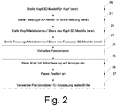
- FIGS. 3A and 3C show a representation for explaining a 3D model of a head.
- 31 denotes an example of a usable coordinate system.
- Fig. 3A is a 3D model 30 in the form of a triangle network with a plurality of nodes, which are connected by lines, shown.
- fig. 3B is shown a combination 31 of the triangle mesh and a texture.
- the Fig. 3C shows a representation 32, as it can be done on the basis of the model on a screen in which only the texture is visible, but not the individual vertices that are in the FIGS. 3A and 3B are shown explicitly for clarity.
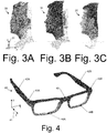
- the Fig. 4 shows a representation of a spectacle frame based on the model together with a coordinate system 41.
- the spectacle frame 40 of Fig. 4 has a right temple piece 42A, a left temple piece 42B, a right hinge 43A, a left hinge 43B, a right frame edge 44A, a left frame edge 44B, and a
- FIG. 12 is a flowchart of a method of determining frame metadata, that is, an example of an implementation of step 23 of FIG Fig. 2 .
- step 50 prominent points in the 3D model of the frame are determined using 3D feature descriptors.
- step 51 these distinctive points are classified and filtered.
- points can also be marked manually, as in FIGS. 6A and 6B is illustrated.
- the spectacle frame 40 which already with reference to the Fig. 4 described on a display and relevant points are marked.
- FIGS. 6A and 6B show as examples Ohrauflagena 61, hinge points 62, positions of nose pads 63 and a center 64 of the nose bridge, which can serve as a support point. It should be noted that the support point does not have to lie directly on the glasses, but especially in the case of nose pads can also be spaced from the actual version.
- step 52 of the Fig. 5 A coordinate transformation into the coordinate system of the major axis of the marked points classified in step 51 is performed by a principal component analysis (PCA), and in step 53, nasal bridges and hinges are located by means of the classified prominent points. Techniques for this have also been described above.
- PCA principal component analysis
- step 54 a point of the nasal bridge support for coarse positioning is then determined as a support point, as already described.
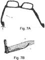
- step 55 the 3D model of the eyeglass frame is segmented into components (left eyeglass temple, right eyeglass temple and the remainder), and in step 56, an overlay area on the temple underside is determined in the form of a platen curve, as already described.
- the strap base on which the pad curve is determined is in Fig. 7A for a spectacle frame 70 and in a corresponding enlarged view of Fig. 7B for the eyeglass temple 71 and 72 shown as a single-point representation.
- FIG. 12 is a flowchart of a method for determining the layup curve, that is, a more detailed implementation of step 56 of FIG Fig. 5 .
- step 80 starting point and end point of the respective bracket part (left eyeglass temple or right temple) are described.
- the procedure of Fig. 8 is carried out separately for the left temple and the right temple.
- step 81 a potential ear pad area is determined, and in step 82, the pad curve is determined using the described sliding window technique.
- the steps 80-82 are carried out as described above in more detail.
- the Fig. 9 shows a flowchart of a method for virtual adjustment and positioning of a spectacle frame on a head, using the models and metadata discussed above.
- the Fig. 9 provides an implementation example for steps 24-26 of Fig. 2 represents.
- step 90 of the Fig. 9 a coarse positioning takes place, wherein the support point of the metadata of the spectacle frame and the touchdown point of the metadata of the head are brought into agreement. Then, in step 91, a bending of the socket takes place, in which case the cylinder-cutting methods already explained are used. In versions where an inclination can be changed, that is, the inclination can be changed by rotation of the stirrup around the x-axis (the coordinate system 41 of FIG Fig. 4 used). Spectacle frames in which the frame metadata indicate that such rotation is not possible, step 92 may be skipped.
- step 93 a fine positioning of the socket in the xy plane is then carried out, in which case the techniques already described above for the fine positioning are used.
- step 94 an image synthesis of the socket and the head is then carried out according to the positioning in steps 90-93, wherein as explained light sources can be taken into account.
- step 95 an interaction of the user with the illustrated model, that is, the display of the socket and the head, with one or more input devices (for example, the input devices 17 of FIG Fig. 1A ).
- a navigation as indicated in step 96 can take place, that is to say the displayed model can be rotated, enlarged or reduced.
- the step 94 is then carried out again, that is to say the image is newly displayed in accordance with the navigation. It can also be an input, also referred to as a gesture, to rotate the socket, inter alia, as described asymmetries in the face to compensate. In this case, then the calculation of the positioning from step 92 again. Finally, the glasses can be moved up and down on the bridge of the nose. This corresponds to a change in the initial coarse positioning, and so in this case the procedure is repeated from steps 90 using the newly determined position on the bridge of the nose as coarse positioning of step 90.
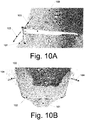
- FIG. 14 shows representations of a head 100 together with a spectacle frame 102 for illustrating method steps of FIG Fig. 9
- the Fig. 10A illustrates how the eyeglass frame 102 on a nose bridge 101 of the head 100 according to arrows 103 can be moved up and down. This is an example for movement on the bridge of the nose according to step 96.
- the Fig. 10B FIG. 12 illustrates a bending of the brackets of the spectacle frame 102 according to arrows 104, as they are in step 91 of FIG Fig. 9 is carried out.
- the Fig. 11 shows a representation to the already explained above rotation of the socket about the x-axis explained by means of a cylinder section.
- the Fig. 11 shows a 3D model of a head 110 and a 3D model of a spectacle frame 111 each as a 3D mesh.
- the socket was first positioned on the basis of a contact point 116.
- An axis 115 extends in the x-direction through the support point 116.
- a cylinder, indicated by circles 112, 113 has a radius to an ear point of the 3D model of the head 110 on.
- the intersection of the cylinder with a support region of the spectacle frame represented by the 3D model of the spectacle frame 111 with the cylinder gives a direction for the spectacle arms of the spectacle frame and thus an angle about which the spectacle frame is to rotate about the axis 115.
- a rotation is carried out so that the eyeglass temples now run in the direction of the lines 1110A, 1110B.
Abstract
Es werden Verfahren, Computerprogramme und Vorrichtungen zur virtuellen Brillenanprobe beschrieben. Hierfür werden 3D-Modelle eines Kopfes und einer Brillenfassung sowie Kopf-Metadaten auf Basis des Modells des Kopfes und Fassungs-Metadaten auf Basis des Modells der Fassung bereitgestellt. Die Kopf-Metadaten umfassen dabei Auflageinformationen, insbesondere einen Auflagepunkt, welcher zum erstmaligen Positionieren der Brillenfassung an dem Kopf dienen kann, und/oder einen Auflagebereich, welcher einen Bereich der Bügel der Fassung zur Auflage auf den Ohren des Kopfes beschreibt. Mit Hilfe derartiger Metadaten kann eine schnelle und verhältnismäßig wenig rechenaufwändige Positionierung der Brillenfassung auf dem Kopf erreicht werden.

Description
Die vorliegende Anmeldung betrifft Verfahren, Vorrichtungen und Computerprogramme zum virtuellen Anpassen von Brillenfassungen. Unter einer Brillenfassung ist dabei in Übereinstimmung mit DIN EN ISO 7998:2006-01 und DIN EN ISO 8624:2015-12 ein Gestell oder eine Halterung zu verstehen, mittels dem/der Brillengläser am Kopf getragen werden können. Der Begriff wie hier verwendet beinhaltet insbesondere auch randlose Brillenfassungen. Derartige Brillenfassungen werden umgangssprachlich auch als Brillengestelle bezeichnet. Ein virtuelles Aufsetzen einer Brillenfassung bezeichnet im Rahmen der vorliegenden Anmeldung ein Anpassen eines Modells einer Brillenfassung an ein Modell eines Kopfes auf einer Recheneinrichtung, üblicherweise verbunden mit einer graphischen Darstellung des Anpassens der Brillenfassung auf einen Kopf einer Person auf einer Anzeige, beispielsweise einem Computerbildschirm.The present application relates to methods, apparatuses and computer programs for the virtual fitting of spectacle frames. Under a spectacle frame is in accordance with DIN EN ISO 7998: 2006-01 and DIN EN ISO 8624: 2015-12 to understand a frame or a holder can be worn by means of the / glasses on the head. The term as used here includes in particular rimless spectacle frames. Such spectacle frames are colloquially referred to as eyeglass frames. Virtual placement of a spectacle frame in the context of the present application refers to fitting a model of a spectacle frame to a model of a head on a computing device, usually associated with a graphical representation of fitting the spectacle frame to a person's head on a display, for example a computer screen.
Ein virtuelles Aufsetzen einer Brillenfassung ist beispielsweise aus der
Die
Die
Von dem Unternehmen Volumental ist ein Demonstrationsvideo der Software "Vacker" auf "https://www.volumental.com/face-scanning/", Stand 5. März 2017, verfügbar, bei welcher ein Kopf mit einer aufgesetzten Brille dargestellt ist und Parameter der Brille mittels Schiebereglern modifizierbar sind, beispielsweise des Sitzes der Brille auf dem Nasenrücken oder auch andere Parameter wie Fassungsscheibenwinkel und Vorneigung (vgl. DIN EN ISO). Auch eine Farbe der Brillenfassung oder eine Farbe der Scharniere der Brillenfassung können ausgewählt werden.From the company Volumental a demonstration video of the software "Vacker" on "https://www.volumental.com/face-scanning/", as of March 5, 2017, is available, in which a head is shown with an attached glasses and parameters the glasses are modifiable by means of sliders, for example, the seat of the glasses on the bridge of the nose or other parameters such as frame angle and preadjustment (see DIN EN ISO). Also, a color of the spectacle frame or a color of the hinges of the spectacle frame can be selected.
Videos, die einen Workflow einer virtuellen Brillenanpassung zeigen, sind auf dem Webportal von Alain Afflelou/Ditto verfügbar, vergleiche beispielsweise "https://www.youtube.com/watch?v=awNs2cEoZ7Y" oder "https://www.youtube.com/watch?v=ZsBV4FkcU8U", Stand 5. März 2017. Dabei wird ein Computer mit integrierter Kamera als Aufnahmesystem genutzt, und es können Fassungen ausgewählt werden. Bei dieser Herangehensweise erfolgt die Brillenanpassung gleichsam auf einem Livevideo des Benutzers, welches über die Kamera aufgenommen wird.Videos that show a workflow of a virtual eyewear adjustment are available on the web portal of Alain Afflelou / Ditto, for example, see "https://www.youtube.com/watch?v=awNs2cEoZ7Y" or "https://www.youtube. com / watch? v = ZsBV4FkcU8U ", March 5, 2017. A computer with an integrated camera is used as the recording system, and versions can be selected. In this approach, the eyewear adjustment takes place as it were on a live video of the user, which is recorded on the camera.
Der oben erläuterte Stand der Technik erlaubt ein virtuelles Aufsetzen einer Brille und beispielsweise bei der
Es ist ausgehend hiervon eine Aufgabe der vorliegenden Erfindung,It is an object of the present invention to provide
Verfahren, Vorrichtungen sowie entsprechende Computerprogramme bereitzustellen, mit denen der Rechenaufwand reduziert werden kann und/oder die Gefahr, dass ein Optimierungsverfahren nicht zu einem Optimum führt, reduziert wird.To provide methods, devices and corresponding computer programs, with which the computational effort can be reduced and / or the risk that an optimization process does not lead to an optimum, is reduced.
Erfindungsgemäß wird ein Verfahren zum virtuellen Aufsetzen einer Brillenfassung nach Anspruch 1, ein Computerprogramm nach Anspruch 14 sowie eine entsprechende Vorrichtung nach Anspruch 15 bereitgestellt. Die Unteransprüche definieren weitere Ausführungsformen.According to the invention, a method for the virtual placement of a spectacle frame according to claim 1, a computer program according to
Erfindungsgemäß wird ein Verfahren zum virtuellen Brillenaufsetzen bereitgestellt, umfassend: virtuelles Feinpositionieren der Brillenfassung auf dem Kopf aus Basis eines 3D-Modells eines Kopfes und eines 3D-Modells einer Brillenfassung.
Gekennzeichnet ist das erfindungsgemäße Verfahren durch ein virtuelles Grobpositionieren der Brillenfassung auf dem Kopf auf Basis von Kopf-Metadaten für das 3D-Modell des Kopfes und von Fassungs-Metadaten für das 3D-Modell der Brillenfassung vor dem Feinpositionieren.According to the invention, there is provided a virtual eyeglass placement method comprising: virtual fine positioning of the eyeglass frame on the head based on a 3D model of a head and a 3D model of a spectacle frame.
The inventive method is characterized by a virtual coarse positioning of the spectacle frame on the head based on head metadata for the 3D model of the head and frame metadata for the 3D model of the spectacle frame before fine positioning.
Das Verfahren kann weiter ein Anzeigen des Kopfes mit der darauf positionierten Brillenfassung umfassen, wobei dieses Anzeigen z.B. mittels einer anderen Recheneinrichtung als das Grob- und/oder Feinpositionieren durchführbar ist.The method may further include displaying the head with the eyeglass frame positioned thereon, which displays e.g. by means of a different computing device than the coarse and / or fine positioning is feasible.
Die Begriffe "Grobpositionieren" und "Feinpositionieren" sind dabei relativ zu verstehen, d.h. das Feinpositionieren präzisiert die zunächst beim Grobpositionieren bestimmte Position.The terms "coarse positioning" and "fine positioning" are to be understood relative, i. The fine positioning makes the position determined during coarse positioning more precise.
Durch das Heranziehen der Kopf-Metadaten und der Fassungs-Metadaten für das Grobpositionieren kann das Grobpositionieren schnell und mit vergleichsweise geringem Rechenaufwand erfolgen. Zudem ergibt sich durch das Grobpositionieren ein Startpunkt für das folgende Feinpositionieren, welcher das Feinpositionieren beschleunigen kann, da das Feinpositionieren bereits von einer annähernd korrekten Position der Brillenfassung gestartet wird. Dies reduziert die Gefahr, dass bei dem Feinpositionieren eine Position gefunden wird, die nicht einem gewünschten Optimum entspricht. Indem für das Feinpositionieren die 3-D Modelle des Kopfes und der Fassung selbst herangezogen werden, kann dann eine hohe Genauigkeit bei der Feinpositionierung erreicht werden, wobei wegen des vorangegangenen Grobpositionierens die Feinpositionierung dann insgesamt weniger rechenaufwändig ist.By using the header metadata and the frame metadata for rough positioning, coarse positioning can be done quickly and with comparatively little computational effort. In addition, the rough positioning results in a starting point for the following fine positioning, which can accelerate the fine positioning, since the fine positioning is already started from an approximately correct position of the spectacle frame. This reduces the risk that in the fine positioning a position is found that does not correspond to a desired optimum. By using the 3-D models of the head and the frame itself for the fine positioning, a high accuracy can be achieved in the fine positioning, whereby the fine positioning is less computationally expensive due to the previous coarse positioning.
Unter einem 3D-Modell ist dabei eine dreidimensionale Repräsentation von realen Objekten zu verstehen, die als Datensatz in einem Speichermedium, beispielsweise einem Speicher eines Computers oder einem Datenträger, vorliegen. Eine solche dreidimensionale Repräsentation kann beispielsweise ein 3D-Netz (englisch "3D mesh"), bestehend aus einem Satz von 3D-Punkten, die auch als Vertices bezeichnet werden, und Verbindungen zwischen den Punkten, die auch als Edges bezeichnet werden. Diese Verbindung bilden im einfachsten Fall ein Dreiecksnetz (englisch triangle mesh). Bei einer derartigen Repräsentation als 3D-Netz wird nur die Oberfläche eines Objekts beschrieben, nicht das Volumen. Das Netz muss nicht notwendigerweise geschlossen sein. Wird also beispielsweise der Kopf in Form eines Netzes beschrieben, so erscheint er wie eine Maske. Näheres zu derartigen 3D-Modellen findet sich in
Eine weitere Möglichkeit der Repräsentation eines 3D-Modells ist ein Voxel-Gitter (englisch "voxel grid"), welches eine volumenhafte Repräsentation darstellt. Dabei wird der Raum in kleine Würfel oder Quader eingeteilt, welche als Voxel bezeichnet werden. Für jedes Voxel wird im einfachsten Fall die An- oder Abwesenheit des darzustellenden Objekts in Form eines Binärwerts (1 oder 0) gespeichert. Bei einer Kantenlänge der Voxel von 1 mm und einem Volumen von 300 mm x 300 mm x 300 mm, was ein typisches Volumen für einen Kopf darstellt, erhält man somit insgesamt 27 Millionen derartiger Voxel. Derartige Volxel-Gitter sind beispielsweise in
Das 3D-Modell des Kopfes und/oder das 3D-Modell der Brillenfassung kann insbesondere ein 3D-Modell mit Textur sein. Unter einem 3D-Modell mit Textur versteht man ein 3D-Modell, in dem zusätzlich die Farbinformation der Oberflächenpunkte des realen Objekts enthalten ist. Durch die Verwendung eines 3D-Modells mit Textur ist eine farbrealistische Darstellung des Kopfes und der Brillenfassung möglich.The 3D model of the head and / or the 3D model of the spectacle frame can in particular be a 3D model with texture. A 3D model with texture is understood to mean a 3D model which additionally contains the color information of the surface points of the real object. By using a 3D model with texture a color realistic representation of the head and the frame is possible.
Dabei kann die Farbinformation direkt in den Vertices als Attribut enthalten sein, zum Beispiel als RGB (Rot Grün Blau)-Farbenwert, oder es wird an jeden Vertex als Attribut ein Paar von Texturkoordinaten gehängt. Diese Koordinaten sind dann als Bildkoordinaten (Pixelpositionen) in einem zusätzlichen Texturbild zu verstehen. Die Textur beispielsweise der oben erwähnten Dreiecke des Dreiecksnetzes wird dann durch Interpolation aus den Pixeln des Texturbildes erzeugt.In this case, the color information can be contained directly in the vertices as an attribute, for example as an RGB (red-green-blue) color value, or a pair of texture coordinates is attached to each vertex as an attribute. These coordinates are then to be understood as image coordinates (pixel positions) in an additional texture image. The texture of, for example, the triangles of the triangle mesh mentioned above is then generated by interpolation from the pixels of the texture image.
Bei der Speicherung als Voxel-Gitter kann die Farbinformation in den Voxeln selbst gespeichert werden. Die Auflösung der Textur entspricht dann bei der Voxel-Darstellung der Größe der Voxel. Für hochauflösende Texturen ist die Umwandlung des Voxel-Gitters in ein Netz, welches die Oberfläche beschreibt, erforderlich, was als Oberflächenrekonstruktion (englisch surface reconstruction) bezeichnet wird. (siehe z.B.
Unter Metadaten sind Daten zu verstehen, welche Informationen über die Merkmale des Modells, jedoch nicht das Modell selbst enthalten. Insbesondere können die Metadaten Zusatzinformationen zu den Modellen liefern und/oder markante Punkte oder Kurven basierend auf dem jeweiligen Modell enthalten. Metadaten sind auch in dem Wikipedia-Artikel "Metadaten", Stand 5. März 2017, allgemein erläutert. Referenzen auf Wikipedia beziehen sich, sofern nichts anderes angegeben ist, auf die deutschsprachige Wikipedia (de.wikipedia.org).Metadata is data that contains information about the features of the model but not the model itself. In particular, the metadata may provide additional information about the models and / or may include prominent points or curves based on the particular model. Metadata are also generally discussed in the Wikipedia article "Metadata," as of March 5, 2017. References to Wikipedia, unless otherwise stated, refer to the German-language Wikipedia (de.wikipedia.org).
Durch die Verwendung derartiger Metadaten, welche vorab erstellt werden können, ist wie oben erwähnt auf einfache Weise eine schnelle Positionierung und auch Änderung der Position der Brillenfassung auf dem Kopf möglich, verglichen mit der Verwendung der kompletten 3D-Modelle, die typischerweise wesentlich umfangreicher sind.By using such metadata, which can be prepared in advance, as mentioned above, it is easily possible to quickly position and also change the position of the spectacle frame on the head, compared to the use of the complete 3D models, which are typically considerably more extensive.
"Virtuell" ist das Positionieren deswegen, weil der Vorgang in einem Rechner wie einem Computer geschieht und nicht die reale Brillenfassung auf den realen Kopf gesetzt wird.Positioning is "virtual" because the process takes place in a computer like a computer and not the real spectacle frame is placed on the real head.
Bevorzugt umfassen die Fassung-Metadaten dabei erste Auflageinformationen, die eine oder mehrere Stellen der Brillenfassung definieren, an denen die Brillenfassung auf dem Kopf aufliegt, und/oder die Kopf-Metadaten dabei zweite Auflageinformationen, die eine oder mehrere Stellen des Kopfes definieren, an denen die Brillenfassung auf dem Kopf aufliegt. Stellen können dabei Punkte, Punktmengen, Kurven oder Flächen sein. Mittels solcher erster und/oder zweiter Auflageinformationen kann das virtuelle Anpassen der Brillenfassung beschleunigt werden, da nicht für alle Berechnungen und Schritte beim Anpassen das gesamte 3D-Modell der Brillenfassung herangezogen werden muss.In this case, the frame metadata preferably comprises first edition information which defines one or more locations of the spectacle frame on which the spectacle frame rests on the head, and / or the header metadata thereby defines second edition information defining one or more locations of the head against which the spectacle frame rests on the head. Positions can be points, points, curves or surfaces. By means of such first and / or second edition information, the virtual adjustment of the spectacle frame can be accelerated since the entire 3D model of the spectacle frame does not have to be used for all calculations and steps in the adaptation.
Bevorzugt umfassen die ersten Auflageinformationen dabei einen Auflagepunkt, welcher einen Punkt im Bereich einer Nasenbrücke der Brillenfassung, insbesondere in einer Mitte der Nasenbrücke der Brillenfassung, kennzeichnet, einen Auflagebereich, der einen Bereich der Brillenbügel der Brillenfassung kennzeichnet.In this case, the first support information preferably comprises a contact point which identifies a point in the region of a nose bridge of the spectacle frame, in particular in a middle of the nose bridge of the spectacle frame, a support region which identifies a region of the spectacle arms of the spectacle frame.
Die Begriffe Nasenbrücke und Brillenbügel werden hier wie in der DIN EN ISO 8624:2015-12, veröffentlicht im Dezember 2015 und der DIN EN ISO 7998:2006-01, veröffentlicht im Januar 2006 verwendet.The terms nose bridge and temple are used here as in DIN EN ISO 8624: 2015-12, published in December 2015 and DIN EN ISO 7998: 2006-01, published in January 2006.
Mittels eines derartigen Auflagepunkts kann die Grobpositionierung der Brillenfassung an dem Kopf erfolgen. Mittels des Auflagebereichs kann die Grobpositionierung ebenfalls unterstützt werden, insbesondere auch wenn weiter unten beschriebene Formänderungen der Brillenfassung durch Biegen und/oder Positionsänderungen der Brillenbügel erforderlich sind. Nasenbrücke und Brillenbügel sind dabei Teile der Brillenfassung, an denen die Brillenfassung typischerweise auf dem Kopf aufliegt, sodass mit dieser Wahl der Metadaten einfach eine den tatsächlichen Gegebenheiten entsprechende Positionierung vornehmbar ist.By means of such a support point, the coarse positioning of the spectacle frame can be made on the head. By means of the support region, the coarse positioning can also be supported, in particular if changes in shape of the spectacle frame described below are required by bending and / or changes in position of the temples. Nose bridge and eyeglass temple are parts of the eyeglass frame, on which the eyeglass frame typically rests on the head, so that with this choice of metadata simply the actual circumstances corresponding positioning is vornehmbar.
Die Fassungs-Metadaten können dabei zusammen mit dem 3D-Modell der Brillenfassung für einer Vielzahl verschiedener Brillenfassungen vorab bestimmt und in einem Speichermedium abgelegt sein, und dann für die Durchführung des Verfahrens abgerufen werden. Auf diese Weise stehen die Daten schnell zur Verfügung.The frame metadata can be determined in advance together with the 3D model of the spectacle frame for a variety of different spectacle frames and stored in a storage medium, and then retrieved for carrying out the method. In this way, the data is available quickly.
Das 3D-Modell des Kopfes kann beispielsweise mittels stereoskopischer Bildaufnahmen erstellt werden. Bei derartigen stereoskopischen Bildaufnahmen wird ein Objekt, in diesem Fall der Kopf aus mehreren Richtungen aufgenommen, wobei die Aufnahmepositionen bekannt sind. Dies kann durch mehrere starr zueinander angeordnete Kameras erfolgen. Durch Identifizierung einander entsprechender Merkmale in den aufgenommen Bildern kann dann unter Berücksichtigung der bekannten Aufnahmepositionen das Modell erstellt werden. Näheres zu einer derartigen Bestimmung von 3D-Modellen findet sich beispielsweise in
Das 3D-Modell der Brillenfassung kann beispielsweise herstellerseitig bereitgestellt werden.The 3D model of the spectacle frame can be provided, for example, by the manufacturer.
Für die Bestimmung der Fassungs-Metadaten gibt es verschiedene Möglichkeiten, wobei die verschiedenen Möglichkeiten auch miteinander kombiniert werden können. Beispielsweise können verschiedene Metadaten der Fassungs-Metadaten mit unterschiedlichen Möglichkeiten bestimmt werden. Derartige Möglichkeiten werden nun erläutert.There are various ways of determining the frame metadata, and the different options can be combined. For example, different metadata of the frame metadata may be determined in different ways. Such possibilities will now be explained.
Bei manchen Ausführungsformen werden die Fassungs-Metadaten manuell bestimmt. Eine derartige manuelle Bestimmung erlaubt eine Bestimmung der Fassung-Metadaten ohne größeren Rechenaufwand und gibt einem Benutzer eine vollständige Kontrolle über die Fassungs-Metadaten. Hierzu kann eine Benutzerschnittstelle bereitgestellt werden, bei der die Brillenfassung auf Basis des Modells graphisch auf einer Anzeige dargestellt wird. Punkte und/oder Konturen der Brillenfassung können dann manuell ausgewählt werden, beispielsweise durch Anklicken mit einer Maus und einem entsprechend dargestellten Mauszeiger oder durch direktes Markieren auf einem berührungsempfindlichen Bildschirm. Dabei kann insbesondere der oben erwähnte Auflagepunkt als einzelner Punkt angeklickt werden, und der Auflagebereich kann als Konturlinie oder Konturpolynom ausgewählt werden. Zudem können als Metadaten Drehachsen an Scharnieren der Brillenfassung manuell markiert werden.In some embodiments, the frame metadata is determined manually. Such manual determination allows determination of the frame metadata without much computational effort and gives a user complete control over the frame metadata. For this purpose, a user interface can be provided in which the spectacle frame is graphically displayed on a display on the basis of the model. Points and / or contours of the spectacle frame can then be selected manually, for example by clicking with a mouse and a correspondingly displayed mouse pointer or by direct marking on a touch-sensitive screen. In this case, in particular, the above-mentioned support point can be clicked as a single point, and the support area can be selected as a contour line or contour polynomial. In addition, rotary axes can be manually marked as metadata on hinges of the spectacle frame.
Bei einer anderen Ausführungsform wird der Auflagebereich beispielsweise als Konturlinie an einer Unterseite jedes Brillenbügels automatisch bestimmt, beispielsweise durch einen Bilderkennungsalgorithmus. In diesem Fall ist keine Benutzereingabe erforderlich.In another embodiment, the support area is automatically determined, for example, as a contour line on an underside of each eyeglass temple, for example by an image recognition algorithm. In this case, no user input is required.
Schließlich wird bei anderen Ausführungsbeispielen eine vollautomatische Bestimmung der Fassungs-Metadaten bereitgestellt. Dies erfolgt bevorzugt mit Verfahren des maschinellen Lernens, wie sie im Wikipedia Artikel "
Bei einem bevorzugten Ausführungsbeispiel umfasst das Bestimmen der Fassungs-Metadaten eine Bestimmung, insbesondere automatische Bestimmung von markanten Punkten in dem 3D-Modell der Fassung. Markante Punkte sind dabei Punkte, die bestimmte, vorgegebene Eigenschaften haben, welche in sogenannten 3D-Merkmalsdeskriptoren (3D-Feature-Deskriptoren) definiert sein können. Solche markanten Punkte stellen ein vergleichsweise kleines Datenvolumen dar, und zur Bestimmung der markanten Punkte können etablierte Algorithmen herangezogen werden. Näheres zu einer solchen Bestimmung markanter Punkte mittels 3D-Merkmalsdeskriptoren ist z.B. in
So bestimmte markante Punkte werden dann bevorzugt in relevante und nicht relevante Punkte klassifiziert. So können nachfolgende Schritte auf die relevanten Punkte eingeschränkt werden, sodass die zu verarbeitende Datenmenge reduziert wird. Dies kann insbesondere mittels Verfahren des Überwachten Lernens (Supervised Learning) geschehen, wie sie in dem Wikipedia Artikel "
Diese Verknüpfung kann dann als Datensatz zu jeder Fassung hinterlegt werden, beispielsweise als .XML-Datei. Die Punkteklassen geben an, welches Element der Brillenfassung der jeweilige Punkt angibt oder wo der jeweilige Punkt auf der Brillenfassung liegt. Beispiele für Punkteklassen sind zum Beispiel "Scharnier außen oben links" für einen Punkt, der an einem linken Brillenscharnier außen und oben liegt, "Scharnier außen unten links" für einen entsprechenden Punkt, der unten liegt, entsprechende Klassen für das rechte Scharnier, "Zentrum-Brücke-Vorne" für einen Mittelpunkt der Nasenbrücke auf der Vorderseite, "Zentrum-Brücke-Hinten" für einen Punkt auf der Nasenbrücke auf einer Rückseite etc. Die Vorderseite ist dabei die Seite der Brillenfassung, welche beim Aufsetzen der Brillenfassung vom Kopf der aufsetzenden Person abgewandt ist, und die Rückseite ist die Seite der Brillenfassung, die dem Kopf der Person zugewandt ist.This link can then be stored as a record for each version, for example as an .XML file. The point classes indicate which element of the eyeglass frame indicates the respective point or where the respective point lies on the eyeglass frame. Examples of point classes are, for example, "hinge outer upper left" for a point located on a left hinge outside and top, "hinge outside bottom left" for a corresponding point lying down, corresponding classes for the right hinge, "center -Bridge-Front "for a midpoint of the nose bridge on the front," center bridge-back "for a point on the nose bridge on a back etc. The front is the side of the spectacle frame, which when putting the spectacle frame from the head of the putting Person is facing away, and the back is the side of the spectacle frame, which faces the head of the person.
Beim unterstützten Lernen gibt es verschiedene mögliche Algorithmen, um so die für die markanten Punkte erlernten Punkteklassen in ein Modell zu überführen und dieses Modell anzuwenden, um dann nach der Lernphase für einen mit einem 3D-Merkmaldeskriptor aufgefundenen Punkt die jeweilige Punkteklasse automatisch zu ermitteln. Siehe hierzu auch "
Ein weiterer möglicher Algorithmus ist die Verwendung einer sogenannten "Support Vector Machine (SVM)", wie sie ebenfalls in der oben erwähnten Software Bibliothek Open CV bereitgestellt wird.Another possible algorithm is the use of a so-called "support vector machine (SVM)", as it is also provided in the above-mentioned software library Open CV.
Mittels derartiger Algorithmen können markante Punkte dann automatisch identifiziert werden, was die Verarbeitung des 3D-Modells der Brillenfassung erleichtert, da nach der Trainingsphase dann keine Benutzereingabe mehr nötig ist, um die markanten Punkte zu identifizieren.By means of such algorithms distinctive points can then be automatically identified, which facilitates the processing of the 3D model of the spectacle frame, since after the training phase then no more user input is necessary to identify the prominent points.
Bevorzugt wird nach der Identifizierung und Klassifizierung der markanten Punkte eine Koordinatentransformation durchgeführt. Durch eine derartige Koordinatentransformation können Fassungs-Metadaten und/oder 3D-Modelle der Fassung für verschiedene Fassungen auf ein gemeinsames Koordinatensystem transformiert werden. Dies erleichtert die nachfolgende Verarbeitung, da für jede Brillenfassung von dem gleichen Koordinatensystem ausgegangen werden kann.Preferably, a coordinate transformation is performed after the identification and classification of the prominent points. By such a coordinate transformation, frame metadata and / or 3D models of the frame for different versions can be transformed to a common coordinate system. This facilitates the subsequent processing since the same coordinate system can be assumed for each spectacle frame.
Bei manchen Ausführungsbeispielen wird eine derartige Koordinatentransformation mittels einer Hauptachsentransformation auf der Menge der als relevant klassifizierten markanten Punkte durchgeführt. Die Hauptachsentransformation (im Englischen "principal component analysis", PCA) ist beispielsweise indem Wikipedia Artikel "
Eine andere Möglichkeit der Koordinatentransformation ist eine regelbasierte Koordinatentransformation durch feste Zuordnung eines Koordinatenursprungs und Richtungen von Koordinatenachsen auf Basis der markanten Punkte. Beispielsweise kann ein markanter Punkte der oben erwähnten Klasse "Zentrum-Brücke-Vorne" als Koordinatenursprung dienen und Differenzvektoren zwischen vorgegebenen Punkten oder Linearkombinationen aus der artigen Differenzvektoren als Koordinatenachsen. So kann die Differenz eines Punktes der oben erwähnten Klasse "Scharnier außen oben rechts" zu einem Punkt der Klasse "Scharnier außen oben links" als Koordinatenachse verwendet werden.Another possibility of the coordinate transformation is a rule-based coordinate transformation by fixed assignment of a coordinate origin and directions of coordinate axes on the basis of the prominent points. For example, a prominent point of the above-mentioned class "center-bridge-front" may serve as a coordinate origin and difference vectors between given points or linear combinations of the like difference vectors as coordinate axes. Thus, the difference of a point of the above-mentioned class "hinge outer upper right" to a point of the class "hinge outer upper left" can be used as a coordinate axis.
Bei einem derartigen Koordinatensystem mit einem Zentrum der Nasenbrücke als Ursprung verläuft dann eine Symmetrieebene der Brillenfassung durch diesen Ursprung. Im Folgenden wird für die Erklärungen angenommen, dass die Brillenbügel der Brillenfassung im Wesentlichen in z-Richtung orientiert sind, eine Verbindungslinie der Scharniere der Brillenfassung parallel zur x-Achse liegt und eine y-Richtung senkrecht hierzu steht. In anderen Worten ist bei aufrechter Haltung des Kopfes als x-Richtung eine horizontale Richtung entsprechend einer Verbindungslinie der Augen des Kopfes definiert, als y-Richtung eine vertikale Richtung definiert und als z-Richtung eine Richtung senkrecht zu der x- und y-Richtung definiert. Die oben erwähnte Symmetrieebene ist dann die y-z-Ebene. Dieses Koordinatensystem dient jedoch nur als Beispiel, und es sind auch andere Anordnungen der Achsen oder auch eine Verwendung von Kugelkoordinaten statt kartesischer Koordinaten möglich.In such a coordinate system with a center of the nose bridge as the origin then runs a plane of symmetry of the spectacle frame by this origin. In the following it is assumed for the explanations that the eyeglass frame of the spectacle frame are oriented substantially in the z-direction, a connecting line of the hinges of the spectacle frame is parallel to the x-axis and a y-direction is perpendicular thereto. In other words, when the head is kept upright as the x-direction, a horizontal direction corresponding to a line connecting the eyes of the head is defined as the y-direction defining a vertical direction and the z-direction defining a direction perpendicular to the x- and y-directions , The above-mentioned plane of symmetry is then the y-z plane. However, this coordinate system serves only as an example, and other arrangements of the axes or even use of spherical coordinates instead of Cartesian coordinates are possible.
Bei einem Ausführungsbeispiel werden dann vorgegebene Komponenten der Brillenfassung lokalisiert. Insbesondere kann die Position von Nasenbrücken und Scharnieren der Brillenfassung bestimmt werden. Dies kann auf Basis der klassifizierten markanten Punkte erfolgen, welche wie bereits oben erläutert manuell ausgewählt werden können oder auch automatisch wie beschrieben bestimmt werden können. Beispielsweise kann die Position der Scharniere der Brille auf Basis von markanten Punkten, die außen oder innen bei den Scharnieren bestimmt wurden, bestimmt werden, insbesondere durch Punkte von Klassen wie "Scharnier außen oben links" und "Scharnier außen unten links" wie oben beschrieben. Bei einem Ausführungsbeispiel erfolgt die Berechnung eines Scharnierachspunktes als Mittelwert derartiger markanter Punkte. Insbesondere kann ein Scharnierachspunkt links gemäß 
Die Nasenbrücke kann in ähnlicher Weise als Durchschnitt von Punkten der Klassen "Zentrum-Brücke-Vorne" und "Zentrum-Brücke-Hinten" wie oben erläutert definiert werden.The nose bridge can similarly be defined as the average of points of the "center-bridge-front" and "center-bridge-rear" classes as explained above.
Bei manchen Ausführungsbeispielen erfolgt zur Bestimmung der Fassungs-Metadaten eine Segmentierung des 3D-Modells der Fassung in Komponenten, wobei die Komponenten insbesondere Komponenten für die Brillenbügel und Komponenten, welche die Brillenfassung abgesehen von den Brillenbügeln beschreiben, umfassen können. Durch eine derartige Segmentierung können die verschiedenen Komponenten einzeln zur Bestimmung von Fassungs-Metadaten analysiert werden, was die zu verarbeitende Datenmenge reduziert. Die Segmentierung kann dabei insbesondere auf Basis der markanten Punkte und/oder auf Basis der Lokalisierung von Nasenbrücke und/oder Scharnieren wie oben erläutert erfolgen.In some embodiments, to determine the frame metadata, a segmentation of the 3D model of the frame into components is performed, wherein the components may include, in particular, components for the temples and components that describe the eyeglass frame apart from the temples. Such segmentation allows the various components to be analyzed individually to determine frame metadata, which reduces the amount of data to be processed. The segmentation can be effected in particular on the basis of the prominent points and / or on the basis of the localization of nose bridge and / or hinges as explained above.
Hierzu können Schnittebenen im Raum definiert werden, welche die Punkte (Vertices) oder Voxel des 3D-Modells unterteilen.You can define section planes in space that divide the vertices or voxels of the 3D model.
Die Schnittebenen können dabei durch einen jeweiligen Aufpunkt p und einen Normalenvektor n, welcher auf der Ebene senkrecht steht, definiert werden. Dann gilt für einen Vertex oder Voxel des 3D-Modells, dessen Position durch Koordinaten v (entsprechend der kartesischen Koordinatendarstellung des Punktes) definiert wird, entweder <v, n> ≤ <p, n> oder <v, n> > <p, n>. Dabei bezeichnet <> das euklidische Skalarprodukt. Der Normalenvektor n ist dabei auf eine Länge 1 normiert, das heißt <n, n> = 1.The cutting planes can be defined by a respective reference point p and a normal vector n, which is perpendicular to the plane. Then, for a vertex or voxel of the 3D model whose position is defined by coordinates v (corresponding to the Cartesian coordinate representation of the point), either <v, n> ≤ <p, n> or <v, n>> <p, n>. Here <> denotes the Euclidean scalar product. The normal vector n is normalized to a length 1, that is, <n, n> = 1.
Je nachdem welche der beiden Relationen gilt, liegt der Punkt v auf der einen oder der anderen Seite der Schnittebene. So ist eine einfache Segmentierung in Komponenten möglich.Depending on which of the two relations applies, the point v lies on one or the other side of the cutting plane. So a simple segmentation in components is possible.
Zur Segmentierung der Brillenfassung kann bei dieser Herangehensweise als Aufpunkt der Schnittebene der jeweilige Scharnierachspunkt verwendet werden, welcher wie oben beschrieben bestimmt werden kann. Als normalen Vektor für die Schnittebene kann dann die z-Achse des Koordinatensystems bei der obigen Koordinatentransformation dienen, das heißt die Richtung, in die die Brillenbügel verlaufen. Die Vertices oder Voxel, für die dann <v, n> ≤ <p, n> definieren den jeweiligen Brillenbügel.For segmentation of the spectacle frame, the respective hinge axis point can be used in this approach as a reference point of the sectional plane, which can be determined as described above. The normal vector for the cutting plane can then be the z-axis of the coordinate system in the above coordinate transformation, that is to say the direction in which the eyeglass temples run. The vertices or voxels for which <v, n> ≤ <p, n> define the respective temple.
Auf Basis der so segmentierten Komponenten können dann weitere Metadaten berechnet werden. So kann der oben erwähnte Auflagebereich der Auflageinformationen auf Basis der segmentierten Brillenbügel berechnet werden. Indem die segmentierten Komponenten verwendet werden, müssen weniger Daten bei der Bestimmung der Metadaten verwendet werden als wenn das komplette 3D-Modell verwendet werden würde, wodurch die Berechnung beschleunigt werden kann.Based on the segmented components, further metadata can be calculated. Thus, the abovementioned bearing area of the bearing information can be calculated on the basis of the segmented eyeglass temple. By using the segmented components, less data must be used in determining the metadata than if the complete 3D model were used, which can speed up the computation.
Zur Bestimmung des Auflagebereichs kann bei einem Ausführungsbeispiel folgendes Verfahren für jeden der segmentierten Brillenbügel verwendet werden:
- Zunächst wird ein Anfangspunkt a und ein Endpunkt b des jeweiligen Brillenbügels aus dem jeweiligen segmentierten Brillenbügel des 3D-Modells der Brillenfassung bestimmt. Bei dem oben genannten Koordinatensystem kann derjenige Punkt des segmentierten Brillenbügels, welcher einen minimalen Wert seiner z-Komponente aufweist, der Anfangspunkt a und ein Punkt, welcher einen maximalen Wert der z-Komponente aufweist, der Endpunkt b sein.
- First, a starting point a and an end point b of the respective eyeglass temple are determined from the respective segmented eyeglass temple of the 3D model of the eyeglass frame. In the above-mentioned coordinate system, the point of the segmented eyeglass temple having a minimum value of its z-component, the starting point a, and a point having a maximum value of the z-component may be the end point b.
Als nächstes wird ein potenzieller Ohrauflagebereich bestimmt. Z-Komponenten von Ebenen, welche diesen potenziellen Ohrauflagebereich begrenzen, können als vorgegebenes Verhältnis α und β zu der Länge des Brillenbügels in z-Richtung verwendet werden, sodass gilt: ![]()
![]()
az ist die z-Komponente des Punktes a, und Iz ist die Länge des Brillenbügels in z-Richtung, entsprechend bz- az. vz ist die z-Komponente eines Vertex oder Voxels des 3D-Modells. Für Vertices oder Voxel, für deren z-Komponente vz die obige Beziehung gilt, gehören zum potenziellen Ohrauflagebereich, das heißt für diese Vertices oder Voxel gilt: ![]()
![]()
![]()
![]()
Der Auflagebereich kann dann als Auflagepunktmenge oder Auflagekurve mittels einer Berechnung mit sich schrittweise verschiebendem Fenster (sliding window) ermittelt werden. Hierzu wird in z-Richtung ein Fenster von fest eingestellter Breite (beispielsweise Breite zwischen 0,5 mm und 3 mm, z.B. 1 mm in z-Richtung) und einer fest eingestellten Schrittweite (beispielsweise ebenfalls zwischen 0,5 mm und 3 mm, zum Beispiel etwa 1 mm) über den potenziellen Ohrauflagebereich geschoben. Für jede Position des Fensters wird zunächst die Menge der Vertices oder Voxel des potenziellen Auflagebereichs, die im Fenster liegen ermittelt. Anschließend wird für jeden dieser Vertices oder Voxel das Skalarprodukt s mit einem Richtungsvektor d gebildet, s = <v, d>, wobei v wieder die Koordinaten des Vertex oder Voxels angibt.The support area can then be determined as a support point quantity or circulation curve by means of a calculation with a sliding window (sliding window). For this purpose, in the z-direction, a window of fixed width (for example, width between 0.5 mm and 3 mm, eg 1 mm in the z direction) and a fixed set step (for example, also between 0.5 mm and 3 mm, for Example, about 1 mm) over the potential ear rest area. For each position of the window, the amount of vertexes or voxels of the potential bearing area that lie in the window is first determined. Subsequently, for each of these vertices or voxels, the scalar product s is formed with a direction vector d, s = <v, d>, where v again indicates the coordinates of the vertex or voxel.
Ein Maximum s dieser Skalarprodukte s ist in der Regel eindeutig einem zugeordneten Vertex oder Voxel mit den Koordinaten v̂ zugeordnet. Falls mehrere maximale Skalarprodukte in einem Fenster vorliegen, wird ein vorbestimmtes Vertex oder Voxel, beispielsweise das zuerst mit dem Maximalwert berechnete, als Vertex oder Voxel v̂ für dieses Fenster genommen. Die Menge der so aufgefundenen Koordinaten v̂ für alle Fenster, geordnet beispielsweise nach aufsteigendem z-Wert, ergibt eine Anordnung von Punkten, welche den Auflagebereich als Auflagekurve charakterisieren. Diese Kurve kann bei Ausführungsbeispielen durch Filter geglättet werden, beispielsweise mittels eines Gaußfilters, oder es kann eine Kurve an die Punkte angepasst werden, beispielsweise eine Spline-Approximation mittels B-Splines durchgeführt werden, wie diese in dem Wikipedia Artikel "
Als Richtungsvektor d wird dabei ein normierter Vektor angenommen, das heißt <d, d> = 1. Dieser kann für den linken und rechten Brillenbügel jeweils fest gewählt werden. Ein Beispiel für einen fest gewählten Richtungsvektor wäre der Vektor (0 , -1 , 0) in dem oben definierten Koordinatensystem. In diesem Fall wäre der Auflagepunkt immer der tiefste Punkt des Brillenbügels. Präziser wird die Lage des Bügels bei nach innen gerichteter Auflagekurve, also z.B. ![]()
![]()
![]()
![]()
Bei manchen Ausführungsbeispielen enthalten die Kopf-Metadaten einen Ohrauflagepunkt, welcher beispielsweise durch manuelles Auswählen eines Punktes auf einer Darstellung der Ohren des Modells gewählt wird. In diesem Fall kann zur Bestimmung des Richtungsvektors d ein Fenster um diesen Ohrauflagepunkt in dem 3D-Modell des Kopfes gewählt werden, zum Beispiel alle Vertices oder Voxel, welche einen z-Wert aufweisen, der maximal eine vorgegebene Distanz, beispielsweise maximal zwischen 0,25 mm und 1 mm, beispielsweise maximal 0,5 mm, von diesem Ohrauflagepunkt entfernt wird. Dann wird der Mittelwert dieses aller Vertices des Fensters bestimmt, und der normierte Differenzvektor Ohrauflagepunkt minus Mittelwert als Richtungsvektor d definiert.In some embodiments, the header metadata includes an ear clip point, which is selected, for example, by manually selecting a point on a representation of the ears of the model. In this case, to determine the direction vector d a window is selected around this ear point in the 3D model of the head, for example all vertices or voxels which have an z value which is a maximum of a predetermined distance, for example a maximum of between 0.25 mm and 1 mm, for example a maximum of 0, 5 mm away from this ear point. Then the mean of this window's vertex is determined, and the normalized difference vector ear point minus mean is defined as the direction vector d.
Auf diese Weise kann eine Auflagekurve als Auflagebereich auf relative einfache Weise automatisch bestimmt werden und dann in weiteren Schritten des Verfahrens zur Positionierung der Brillenfassung an dem Kopf verwendet werden, wie später noch näher erläutert werden wird.In this way, a support curve can be automatically determined as a support area in a relatively simple manner and then used in further steps of the method for positioning the spectacle frame on the head, as will be explained in more detail later.
Zur Beschleunigung der Anpassung können die Fassungs-Metadaten zudem erwartete Ohrauflagepunkte an den Brillenbügeln umfassen, welche manuell ausgewählt werden können. Diese erwarteten Ohrauflagepunkte können dann als Startpunkt beim virtuellen Positionieren der Brille dienen, das heißt die Brille wird zunächst mit diesen Punkten auf den Ohren platziert. Dies kann das virtuelle Positionieren beschleunigen.To speed up the adaptation, the frame metadata may also include expected ear points on the temples, which may be manually selected. These expected ear points can then serve as a starting point for the virtual positioning of the glasses, that is, the glasses are first placed with these points on the ears. This can speed up virtual positioning.
Zudem können die Metadaten im Falle von Brillenfassungen, welche Nasenpads aufweisen, Punkte umfassen, welche die Position derartiger Nasenpads bezeichnen. Auch diese Punkte können manuell ausgewählt werden oder mit maschinellem Lernen bestimmt werden.In addition, in the case of spectacle frames having nose pads, the metadata may include dots indicating the position of such nose pads. These points can also be selected manually or determined by machine learning.
Die Fassungs-Metadaten können zudem Biegeinformationen hinsichtlich einer Biegefähigkeit der Fassung, insbesondere der Brillenbügel umfassen. Mit derartigen Informationen kann die Brille dann beim virtuellen Positionieren virtuell durch Biegen an den Kopf angepasst werden, und diese Anpassungen können dann auf eine entsprechende reale Brillenfassung angewendet werden. Beispiele für derartige Informationen sind beispielsweise eine Information, ob und wie weit eine Rotation um Scharnierachsen möglich ist (zum Beispiel bei Kunststofffassungen mit gefedertem Scharnier) Brillenscharniere haben einen Anschlag - z.B. bei maximaler Öffnung von 180 Grad. Dieser Anschlag kann bei einigen Scharnieren mittels einer Feder realisiert sein, so dass eine Öffnung über 180 Grad hinaus möglich ist. Bei festem Anschlag ohne Feder wird bei Aufbiegung der Bügel deformiert. Es wird in der Information als z.B. ein Typ des Scharniers kodiert - also fix oder gefedert. Zusätzlich wird die Flexibilität des Bügels kodiert; bei gefederten Scharnieren wird dabei ein starres Modell des Bügels verwendet. Ein weiteres Beispiel ist eine Information über eine mögliche Verstellung der Inklination am Brillenbügel, das heißt eine Rotation der Brillenbügel um die x-Achse relativ zur restlichen Brillenfassung. Dies ist bei vielen Metallfassungen durch Verbiegung der Bügel an den Scharnieren nach oben oder unten möglich.The frame metadata may also include bending information regarding a bendability of the frame, in particular the temple. With such information, the glasses can then be virtually adjusted in virtual positioning by bending to the head, and these adjustments can then be applied to a corresponding real eyeglass frame. Examples of such information are, for example, information as to whether and how far a rotation about hinge axes is possible (for example, in the case of plastic hinged hinges). Eyeglass hinges have a stop - eg at a maximum opening of 180 degrees. This stop can be realized with some hinges by means of a spring, so that an opening beyond 180 degrees is possible. A firm stop without spring deforms the bow when bent. It is coded in the information as eg a type of the hinge - thus fixed or sprung. In addition, the flexibility of the strap is coded; Spring-loaded hinges use a rigid model of the bracket. Another example is information about a possible adjustment of the inclination on the eyeglass temple, that is to say a rotation of the eyeglass temple about the x-axis relative to the rest of the eyeglass frame. This is with many Metal frames possible by bending the brackets on the hinges up or down.
Diese Information kann auch angeben, dass keine Verstellung der Inklination möglich ist. Die Information kann beispielsweise als Ja/Nein-Information (Verstellen der Inklination möglich oder nicht) oder auch als Winkelbereich, innerhalb dem die Inklination verändert werden kann, vorliegen.This information may also indicate that no adjustment of the inclination is possible. The information may, for example, be present as yes / no information (adjustment of the inclination possible or not) or also as an angle range within which the inclination can be changed.
Zudem kann ein Aufbiegen der Brillenbügel selbst definiert werden, beispielsweise mittels einer Biegefunktion. Als eine derartige Biegefunktion kann beispielsweise ein multivariates Polynom über der z-Achse und einem Offset in x- und xy-Richtung beschreiben. Zudem kann auch die durch ein Aufbiegen der Bügel hervorgerufene Deformation des Fassungsrandes der Brillenfassung modelliert werden, beispielsweise durch ein multivariates Polynom oder eine multivariate Spline-Funktion (zum Beispiel Tensorprodukt einer B-Spline-Basis, siehe
Ein derartiges Aufbiegen ist insbesondere bei dünnen Brillenbügeln oder sehr elastischen Brillenbügeln möglich.Such bending is possible in particular with thin temple straps or very elastic temple straps.
Die obigen Informationen können für Verbiegungen und Anpassungen der Brillenbügel in verschiedenen Richtungen, beispielsweise in x- und y-Richtung gemäß dem obigen Koordinatensystem, bereitgestellt werden.The above information may be provided for deflections and adjustments of the temples in various directions, for example in the x and y directions according to the above coordinate system.
Als nächstes werden Varianten und Bestimmungsmöglichkeiten für die Kopf-Metadaten gemäß verschiedenen Ausführungsformen diskutiert.Next, variations and determinations for the header metadata according to various embodiments will be discussed.
Bevorzugt umfassen die Kopf-Metadaten eine Position der Augen, welche dann für eine horizontale Ausrichtung der Brillenfassung verwendet werden können. Diese Metadaten geben beispielsweise die Position der Augen, beispielsweise der Pupillen in Nullblickrichtung (siehe DIN EN ISO 13666:2013-10, 5.33), als Punktkoordinaten an. Des Weiteren können die Kopf-Metadaten Ohraufsetzpunkte, wie bereits oben erwähnt, umfassen, welche einen Auflagepunkt der Brillenbügel auf den Ohren angeben. Durch diese Metadaten ist eine einfache Positionierung der Brillenbügel auf den Ohren möglich.Preferably, the header metadata includes a position of the eyes which can then be used for horizontal alignment of the eyeglass frame. For example, these metadata indicate the position of the eyes, for example of the pupils in the zero-viewing direction (see DIN EN ISO 13666: 2013-10, 5.33), as point coordinates. Furthermore, the head metadata may include ear attachment points, as already mentioned above, which indicate a bearing point of the earhooks on the ears. This metadata makes it easy to position the eyeglasses on the ears.
Zudem können die Kopf-Metadaten einen Aufsetzpunkt und/oder eine Beschreibung des Nasenrückens umfassen. Diese Metadaten können zur Grobpositionierung der Brillenfassung am Kopf dienen. Der Aufsetzpunkt ist dabei ein Punkt an oder bei der Nase im 3D-Modell des Kopfes, welcher insbesondere mit einer Grobpositionierung mit dem oben erwähnten Auflagepunkt der Fassungs-Metadaten in Übereinstimmung gebracht werden kann.In addition, the header metadata may include an attachment point and / or a description of the nasal bridge. This metadata can be used for coarse positioning of the eyeglass frame on the head. The touchdown point is a point at or at the nose in the 3D model of the head, which can be brought in particular with a coarse positioning with the above-mentioned contact point of the frame metadata in accordance.
Derartige Kopf-Metadaten können wie bereits für die Fassung-Metadaten wie oben diskutiert manuell bestimmt werden, beispielsweise durch Auswählen entsprechender Punkte oder Kurven in einer Darstellung des Kopfes auf Basis des 3D-Modells. Sie können aber auch ganz oder teilweise automatisch bestimmt werden, beispielsweise mit maschinellem Lernen wie oben diskutiert.Such header metadata may be manually determined as previously discussed for the revision metadata as discussed above, for example by selecting corresponding points or curves in a representation of the head based on the 3D model. However, they can also be determined completely or partially automatically, for example with machine learning as discussed above.
Bei anderen Ausführungsformen werden zusätzlich zu dem 3D-Modell des Kopfes zweidimensionale Bilddaten des Kopfes zur automatischen Bestimmung von Kopf-Metadaten herangezogen. Derartige 2D-Bilder stehen ohnehin zur Verfügung, wenn das 3D-Modell mittels Kameraaufnahmen des Kopfes von mehreren kalibrierten Positionen erstellt wird. Kalibrierte Positionen bedeutet, dass die die Positionen der Bildaufnahmen bekannt sind, sodass auf Basis der aufgenommen Bilder und der Positionen dann das 3D-Modell berechnet werden kann. Alternativ können 2D-Bilder auch aus dem 3D-Modell mit Textur durch Bildsynthese (auch als Rendern bezeichnet) erzeugt werden. Informationen hierzu sind beispielsweise im Artikel "
In derartigen 2D-Bildern können dann Gesichtsmerkmale der Person wie Augenlider, Augenbrauen, Nasenrücken, Augen und dergleichen durch Bilderkennungsverfahren (auch als Objektdetektoren bezeichnet) identifiziert werden. Geeignete Verfahren hierzu sind beispielsweise in der Software-Bibliothek "dlib", "http://blog.dlib.net/2014/08/real-time-face-pose-estimation.html", Stand 10. März 2017, bereitgestellt oder in
Diese so identifizierten Punkte oder Bereiche in dem zweidimensionalen Bild werden anschließen auf das 3D-Modell (beispielsweise das 3D-Netz) des Kopfes projiziert und stehen somit als 3D-Punke als Kopf-Metadaten zur Verfügung. Bei einer bevorzugten Ausführungsform wird zur Projektion eine inverse Projektionsmatrix verwendet. Die Projektionsmatrix setzt sich dabei aus einer Festkörpertransformation von dem Koordinatensystem des Modells, beispielsweise 3D-Netzes, in das Kamerakoordinatensystem der verwendeten Kamera und der Kameramatrix zusammen. Diese Matrizen sind, wenn wie oben beschrieben, eine Kameraeinrichtung mit kalibrierten Positionen für die Bildaufnahme zur Aufnahme des 3D-Modells sowie des 2D-Bildes verwendet wird, gegeben oder werden im Rahmen der Bestimmung des 3D-Modells aus den aufgenommen Bildern bestimmt.(Siehe
Auf diese Weise kann die Projektion schnell erfolgen, da die erforderlichen Matrizen bereits aus der Bestimmung des 3D-Modells bekannt sind. Bei einer alternativen Ausführungsform können Gesichtsmerkmale in den 2D-Bildern auch von Hand markiert werden, wozu das 2D-Bild auf einer Anzeige dargestellt werden kann. Auch Mischformen sind möglich, bei welchen die Gesichtsmerkmale automatisch wie oben erläutert bestimmt werden und dann von Hand noch eine Korrektur erfolgen kann.In this way, the projection can be done quickly because the required matrices are already known from the determination of the 3D model. In an alternative embodiment, facial features in the 2D images may also be marked by hand, for which purpose the 2D image may be displayed on a display. Mixed forms are also possible in which the facial features are automatically determined as explained above and then a correction can be made by hand.
Der oben erwähnte Nasenrückenbereich kann als eine 3D-Kurve bereitgestellt werden. Hierzu kann ein Verfahren entsprechend dem Verfahren zum Bestimmen des Auflagebereichs der Brillenbügel wie bereits oben beschrieben zum Einsatz kommen. Insbesondere kann das oben beschriebene Verfahren mit gleitendem Fenster verwendet werden, wobei als Richtungsvektor d der obigen Formeln eine Richtung des Kopfes (welche beispielsweise eine Koordinatenachse wie die z-Achse des 3D-Modells) sein kann, welche in Kopfrichtung nach hinten orientiert ist. Diese Richtung kann bei der Bestimmung des Kopfes mitbestimmt werden. Der Richtungsvektor d entspricht hier der Richtung der Kopfdrehung bzw. der Blickrichtung wie in der europäischen Patentanmeldung
Wie für den Auflagebereich kann auch hier eine Filterung beispielsweise mittels Gaußfiltern und/oder eine Spline-Approximation durchgeführt werden.As for the support area, a filtering can also be performed here, for example by means of Gaussian filters and / or a spline approximation.
Als Parametrisierung der Kurve des Nasenrückens wird hier das Intervall auf der y-Achse verwendet. Man erhält also eine Funktion, die für jeden y-Wert den zugehörigen 3D-Punkt auf dem Nasenrücken liefert.The interval on the y-axis is used here as the parameterization of the curve of the nose bridge. So you get a function that provides the corresponding 3D point on the bridge of the nose for every y-value.
Der oben erwähnte Aufsatzpunkt kann dann auf Basis dieser 3D-Kurve für den Nasenrückenbereich bestimmt werden. Hierzu wird bei einer Ausführungsform eine Ebene, in welcher eine Verbindungslinie der Augenpositionen des 3D-Modells liegt und in welcher die Blickrichtung liegt, mit der Nasenrückenkurve geschnitten, was einen Startpunkt s für die Bestimmung des Auflagepunkts dient. In einer Umgebung dieses Punktes s, beispielsweise innerhalb eines vorgegebenen Bereichs (einer vorgegebenen Distanz, beispielsweise ± 3 mm, ± 2 mm etc.) wird dann derjenige Punkt der Nasenrückenkurve bestimmt, welcher den kleinsten Wert in Blickrichtung aufweist, das heißt am weitesten hinten (Richtung des Hinterkopfs des 3D-Modells) gelegen ist. Zum y-Wert dieses Punktes kann noch ein fester Offset in y-Richtung addiert werden, um den y-Wert und mittels obiger Parametrisierung der Kurve den Aufsetzpunkt zu ermitteln. Auf diese Weise kann ein Aufsetzpunkt ermittelt werden, welcher zusammen mit dem Auflagepunkt der Fassungs-metadaten für eine anfängliche Positionierung der Brillenfassung verwendet werden kann, die relative nahe an einer endgültigen Position liegt, was eine nachfolgende Optimierung beschleunigen kann.The above-mentioned attachment point can then be determined on the basis of this 3D curve for the nose bridge region. For this purpose, in one embodiment, a plane in which a connecting line of the eye positions of the 3D model lies and in which the viewing direction lies is cut with the nose-back curve, which serves as a starting point s for the determination of the support point. In an environment of this point s, for example, within a predetermined range (a predetermined distance, for example, ± 3 mm, ± 2 mm, etc.), that point of the nose-back curve is determined which has the smallest value in the viewing direction, that is, furthest back (FIG. Direction of the back of the 3D model). For the y value of this point, a fixed offset in the y direction can still be added to determine the y value and by means of the above parameterization of the curve the touchdown point. In this way, a touchdown point can be determined which, together with the support point of the socket metadata, can be used for initial positioning of the eyeglass frame that is relatively close to a final position, which can accelerate subsequent optimization.
Die Kopf-Metadaten können dann zusammen mit dem 3D-Modell des Kopfes abgespeichert werden und somit für verschiedene Fassung verwendet werden. Dies erspart Neuberechnungen der Kopf-Metadaten für verschiedene Fassungen.The head metadata can then be stored together with the 3D model of the head and thus be used for different version. This saves recalculation of the header metadata for different versions.
Das virtuelle Positionieren auf Basis der Metadaten kann bevorzugt eine Grobpositionierung auf Basis der Metadaten umfassen, um einen Startpunkt für die nachfolgende weitere Anpassung bereitzustellen. Hier kann insbesondere der oben erwähnte Aufsetzpunkt auf dem Nasenrücken mit dem Auflagepunkt der Brillenfassung in Übereinstimmung gebracht werden. Dabei kann die z-Achse der Fassung (das heißt die Richtung der Brillenbügel) mit einer entsprechenden Achse des 3D-Modells des Kopfes, welche die Blickrichtung bezeichnet, zur Deckung gebracht werden.The virtual positioning based on the metadata may preferably include coarse positioning based on the metadata to provide a starting point for the subsequent further adaptation. Here, in particular, the above-mentioned attachment point on the bridge of the nose can be brought into conformity with the contact point of the spectacle frame. In this case, the z-axis of the socket (that is, the direction of the eyeglass temple) can be brought into coincidence with a corresponding axis of the 3D model of the head, which denotes the viewing direction.
Nach diesem Teil der Grobpositionierung kann bei einer Ausführungsform die Fassung derart um die x-Achse rotiert, das heißt die Vorneigung der Fassung verändert, dass der Auflagebereich der Brillenbügel auf den Ohrauflagepunkten anliegt. Dies wird zunächst für jeden Bügel getrennt durchgeführt. Hierzu wird bei einer Ausführungsform ein Schnitt des Auflagebereichs mit einer Zylinderfläche berechnet, wobei die Zylinderfläche die Zylinderachse mit der Rotationsachse der Fassung (in dem obigen Koordinatensystem der x-Achse) übereinstimmt. Die Rotationsachse verläuft dabei durch den Auflagepunkt. Der Radius des Zylinders ist der Abstand des jeweiligen Ohrauflagepunktes von der Rotationsachse. Der Schnittpunkt auf dem Zylinder ergibt direkt den Winkel, um den die Fassung vorgeneigt wird oder zurückgeneigt wird. Der Zylinderschnitt kann dabei durch iterative Linienzylinderschnitte berechnet werden. Dabei kann der Auflagebereich (beispielsweise die oben ermittelte Auflagekurve) zunächst in vergröberter Segmentdarstellung verwendet werden, das heißt mit geringerer Auflösung, um die Berechnung zu beschleunigen. Beispielsweise kann im einfachsten Fall als vergröberte Segmentdarstellung die Verbindungslinie zwischen dem oben erwähnten Anfangspunkt a und Endpunkt b verwendet werden.After this part of the coarse positioning, in one embodiment, the socket can be rotated around the x-axis, that is to say the pretilt of the socket changes, so that the support area of the temple piece rests on the ear support points. This is done separately for each hanger. For this purpose, in one embodiment, a section of the support area is calculated with a cylindrical surface, wherein the cylindrical surface is the cylinder axis coincides with the rotational axis of the socket (in the above x-axis coordinate system). The rotation axis runs through the support point. The radius of the cylinder is the distance of the respective ear contact point from the axis of rotation. The point of intersection on the cylinder directly gives the angle by which the socket is bent or reclined. The cylinder section can be calculated by iterative line cylinder sections. In this case, the support area (for example, the support curve determined above) can initially be used in a coarser segment representation, that is to say with a lower resolution, in order to accelerate the calculation. For example, in the simplest case, as coarsened segment representation, the connecting line between the above-mentioned starting point a and end point b may be used.
Diese Bestimmung mittels iterativer Linienzylinderschnitte kann wie folgt vorgenommen werden: Der Schnittpunkt dieser Verbindungslinie mit dem Zylinder sei mit S bezeichnet. Dann wird bei einer iterativen Verfeinerung die z-Koordinate zS von S verwendet, um einen zugehörigen realen Kurvenpunkt zu ermitteln. Dieser liegt zwar nicht mehr auf der Zylinderfläche, kann dennoch als Näherung verwendet werden, um den Winkel zu bestimmen. Zusätzlich kann bei nun ein weiterer Iterationsschritt durchgeführt werden. Dabei werden Punkte k(zs - ε) und k(zs + ε) auf der Kurve mit einem Abstand ε um zS verwendet, die in einer nächsten Iteration als neue Anfangs- und Endpunkte anstatt von a und b fungieren.This determination by means of iterative line cylinder sections can be made as follows: The point of intersection of this connection line with the cylinder is denoted by S. Then, in an iterative refinement, the z-coordinate z S of S is used to determine an associated real curve point. Although this is no longer on the cylinder surface, it can still be used as an approximation to determine the angle. In addition, another iteration step can now be performed. In this case, points k (z s - ε) and k (z s + ε) on the curve with a distance ε around z s are used, which in a next iteration function as new start and end points instead of a and b.
Nach dieser Positionierung erfolgt ein Biegen der Fassung, wozu die oben erwähnten Biegeinformationen der Fassungs-Metadaten, welche eine Biegefähigkeit der Fassung beschreiben, herangezogen werden.After this positioning, the frame is bent, for which purpose the above-mentioned bending information of the frame metadata, which describes a bendability of the frame, is used.
Hierzu kann wieder das oben beschriebene Verfahren mit Zylinderschnitten angewendet werden. Falls die Biegeinformation wie oben diskutiert als multivariate Biegefunktion vorliegt, kann eine Optimierung durchgeführt werden, bei der als Kostenfunktion ein Abstand des Ohrauflagepunktes von dem Auflagebereich des Bügels verwendet wird. Eine Kostenfunktion ist dabei allgemein eine Funktion, welche sich in Abhängigkeit von einem oder mehreren zu optimierenden Parametern verändert und zur Optimierung auf ein Maximum oder Minimum gebracht wird. Der für die Stärke der Biegung verantwortliche Parameter der Biegefunktion wird dabei als zu optimierender Parameter gewählt. Bei einer einfachen polynomialen Biegefunktion für die Aufbiegung in x-Richtung ist eine Näherung der mathematischen Umkehrfunktion ebenfalls durch ein Polynom möglich. Hierfür wird für eine Verbiegung in x-Richtung an der Stelle z die Biegefunktion Dz(x) additiv als Polynom modelliert; die Umkehrfunktion Dz -1(d) davon wird ebenfalls durch ein Polynom angenähert, z.B. indem man an einzelnen diskreten Stellen [x1,x2,..,xn] die Funktion abtastet und eine neue Polynomapproximation auf [Dz (x1), Dz (x2),..., Dz (xn)] mit Werten [Dz -1(Dz (x1)), Dz -1(Dz(z2)),..., Dz -1(Dz(xn))] durchführt.. In diesem Fall kann direkt die Aufbiegung der Auflagekurve auf den x-Wert des Ohransatzpunktes ermittelt werden, indem die Umkehrfunktion für z=Auflageposition und x=Differenz Ohransatz zu Auflagepunkt angewendet wird.For this purpose, the method described above with cylinder cuts can be used again. If the bending information is a multivariate bending function as discussed above, an optimization may be performed using as cost function a distance of the ear attachment point from the support area of the temple. A cost function is generally a function which changes depending on one or more parameters to be optimized and is brought to a maximum or minimum for optimization. The parameter of the bending function responsible for the strength of the bend is selected as the parameter to be optimized. In a simple polynomial bending function for the bending in the x direction, an approximation of the mathematical inverse function is also possible by a polynomial. For this purpose, for a bending in the x direction at the point z, the bending function D z (x) is additionally modeled as a polynomial; the inverse function D z -1 (d) of which is also approximated by a polynomial, for example, by giving individual discrete ones Let [x1, x2, .., xn] sample the function and apply a new polynomial approximation to [D z (x1), D z (x2), ..., D z (xn)] with values [D z -1 ( D z (x1)), D z -1 (D z (z2)), ..., D z -1 (D z (xn))]. In this case, the deflection of the support curve on the x Value of the ear attachment point can be determined by applying the inverse function for z = support position and x = difference ear approach to support point.
Das Biegen der Fassung kann auch eine Anpassung der Inklination an den Bügel durch Rotation in z-Richtung durchgeführt werden (das heißt eine Verbiegung der Bügel um die x-Achse). Auch hier kann wieder die oben erwähnte Zylinderschnittmethode verwendet werden, wobei der Ohransatzpunkt für die Konstruktion des Zylinders verwendet wird und mit der Auflagekurve geschnitten wird.Bending of the socket can also be done by adjusting the inclination to the yoke by rotation in the z-direction (ie bending the yokes about the x-axis). Again, the above-mentioned cylinder cutting method can again be used, the ear starting point is used for the construction of the cylinder and is cut with the support curve.
Bei einer bevorzugten Ausführungsform ist die Feinpositionierung der Fassung zumindest im Wesentlichen auf eine x-y-Ebene beschränkt. Im Wesentlichen bedeutet dabei, dass eine Positionsveränderung in z-Richtung zumindest nicht mehr als 10% oder nicht mehr als 5% einer Positionsveränderung in der x-y-Ebene beträgt, insbesondere auch 0 sein kann. Dabei wird die Fassung in x-y-Richtung verschoben, bis keine Kollision zwischen dem 3D-Modell der Brillenfassung und dem 3D-Modell des Kopfes vorliegt. Für diese Feinpositionierung kann die Oberfläche des 3D-Modells des Kopfes geringfügig abgesenkt werden (beispielsweise zwischen 0,3 mm und 1 mm), um eine Verformung der Haut an Auflageflächen der Brillenfassung zu berücksichtigen. Auf diese Weise kann eine realistischere Anpassung ermöglicht werden. Keine Kollision bedeutet in diesem Fall, dass das 3D-Model der Fassung und das 3D-Modell des Kopfes keine gemeinsamen Raumbereiche aufweisen. Nach der Feinpositionierung kann der oben genannte Biegevorgang erneut durchgeführt werden, um die Anpassung weiter zu verbessern.In a preferred embodiment, the fine positioning of the socket is at least substantially limited to an x-y plane. In essence, this means that a change in position in the z-direction is at least not more than 10% or not more than 5% of a change in position in the x-y plane, and in particular can also be zero. The frame is shifted in the x-y direction until there is no collision between the 3D model of the spectacle frame and the 3D model of the head. For this fine positioning, the surface of the 3D model of the head can be lowered slightly (for example, between 0.3 mm and 1 mm) in order to take into account deformation of the skin on bearing surfaces of the spectacle frame. In this way, a more realistic adaptation can be made possible. In this case, no collision means that the 3D model of the frame and the 3D model of the head do not share common space. After the fine positioning, the above-mentioned bending operation can be performed again to further improve the matching.
Bei einer bevorzugten Ausführungsform kann nach diesem Schritt eine prinzipielle Eignung der Brillenfassung für den jeweiligen Kopf ermittelt werden, indem überprüft wird, ob ein unterer Rand der Brillenfassung mit einem Wangenbereich des Kopfes in den jeweiligen Modellen kollidiert.In a preferred embodiment, after this step, a basic suitability of the spectacle frame for the respective head can be determined by checking whether a lower edge of the spectacle frame collides with a cheek area of the head in the respective models.
Bei Fassungen mit Nasenpads, wie sie häufig bei Metallfassungen vorliegt, kann das virtuelle Positionieren weiter ein Positionieren der Nasenpads umfassen. Diese Anpassung wird bei einem Ausführungsbeispiel als Rotation der Nasenpads um ein Rotationszentrum modelliert. Hierzu können die Nasenpads vom restlichen Teil der Brillenfassung segmentiert werden, was wie oben erwähnt geschehen kann. Diese Anpassung kann nachdem oben genannten Biegen vorgeführt werden. Die Feinpositionierung kann bei jeder Änderung der Nasenpads erneut durchgeführt werden.For nose pad versions, as is often the case with metal frames, virtual positioning may further include positioning the nose pads. This adaptation is modeled in one embodiment as rotation of the nose pads about a center of rotation. For this purpose, the nose pads can be segmented from the remaining part of the spectacle frame, which can be done as mentioned above. This adjustment can bend after the above be demonstrated. The fine positioning can be performed again with each change of the nose pads.
Als Rotationsachsen können Hauptachsen der Nasenpads gewählt werden, welche beispielsweise mit der oben erwähnten Hauptkomponentenanalyse bestimmt werden können. Die Rotation kann auf zwei Winkel um die beiden sich aus der Hauptkomponentenanalyse ergebenden Hauptachsen zu den größten Eigenwerten eingeschränkt werden Als Kostenfunktion für eine Optimierung der Position der Nasenpads kann ein Kehrwert der Fläche, auf der die Nasenpads die Nase berühren, verwendet werden, um eine möglichst breite Auflage zu erreichen. Auf diese Weise kann auch die Position der Nasenpads virtuell angepasst werden, was dann auf eine reelle Fassung übertragen werden kann. Auf diese Weise ist die Anpassung der Nasenpads an der realen Fassung an den realen Kopf nicht oder nur noch in sehr geringem Umfang nötig.As axes of rotation, main axes of the nose pads can be selected, which can be determined, for example, with the above-mentioned principal component analysis. The rotation can be restricted to two angles around the two major axes resulting from the principal component analysis to the largest eigenvalues. As a cost function for optimizing the position of the nose pads, a reciprocal of the area where the nose pads contact the nose can be used to maximize one reach wide circulation. In this way, the position of the nose pads can be virtually adapted, which can then be transferred to a real version. In this way, the adaptation of the nose pads on the real version of the real head is not necessary or only to a very small extent.
Bei manchen Ausführungsformen kann bei dieser Veränderung der Inklination eine bestimmte voreinstellbare Vorneigung (beispielsweise 9°) vorgegeben werden. Diese fest eingestellte Vorneigung bleibt dann durch Veränderung der Inklination erhalten, auch wenn die Brille später verschoben wird, wie später näher erläutert werden wird.In some embodiments, with this change in inclination, a certain presettable prone (eg 9 °) may be specified. This fixed pre-tilt will then be maintained by changing the inclination, even if the glasses are later moved, as will be explained later.
Das Anzeigen des Kopfes mit der darauf positionierten Brillenfassung kann mittels herkömmlicher Bildsyntheseverfahren geschehen, siehe den oben erwähnten Wikipedia-Artikel zur Bildsynthese. Hierzu können als Textur insbesondere Kamerabilder verwendet werden, welche auch zum Erstellen des 3D-Modells dienten, da dies einen natürlichen Bildeindruck ergibt. Für die Bildsynthese kann eine Beleuchtung eingestellt oder vorgegeben werden, und die Bildsynthese kann dann beispielsweise mittels sogenanntem Raytracing (Strahlverfolgung) erfolgen, siehe Wikipedia-Artikel "
Hierfür können virtuelle Lichtquellen entsprechend einer Umgebungsbeleuchtung beim Aufnehmen der Bilder des Kopfes verwendet werden. Bevorzugt wird diese Umgebungsbeleuchtung bei dem Aufnehmen der Bilder bestimmt. Um diese Umgebungsbeleuchtung zu bestimmen, kann insbesondere an dem Kamerasystem, welches zur Bildaufnahme für die Erstellung des 3D-Modells des Kopfes verwendet wird, eine Panoramakamera (das heißt eine Panoramakamera mit großem Bildwinkel) verwendet werden, welche die Umgebung aufnimmt, um Lichtquellen zu identifizieren. Bei anderen Ausführungsformen können derartige Systeme zur Bildaufnahme zum Erstellen des 3D-Modells eine Beleuchtungseinrichtung in bekannter Position aufweisen, die dann auch als Position einer Beleuchtung für die Bildsynthese verwendet wird. Bei dieser Bildsynthese können Brillengläser in der Fassung mit berücksichtigt werden, um dem Betrachter einen möglichst natürlichen Bildeindruck zu geben. In diesem Fall können insbesondere Reflexe, welche sich bei Verwendung von Spiegelungsschichten ergeben, berücksichtigt werden. Bei einer bevorzugten Ausführungsform sind Modelle für verschiedene Typen von Entspiegelungsschichten vorhanden, so wie Modelle für verschiedene Glastypen, um dem Benutzer einen Eindruck über verschiedene Schichten zu geben. Bei der Bildsynthese erscheint die Wirkung von Entspiegelungsschichten dabei insbesondere in Form von Reflexen in der Seitenansicht.
Das Verfahren kann weiterhin ein Verändern der Position der Brillenfassung auf Basis von Benutzereingaben umfassen. So kann der Benutzer den Sitz einer Brille nach seinen Wünschen anpassen, oder ein Optiker kann noch Modifikationen vornehmen. Hierzu kann dem Benutzer eine geeignete Benutzeroberfläche bereitgestellt sein, beispielsweise kann die Navigation durch Mausbewegungen oder durch Berühren eines berührungsempfindlichen Bildschirms (Touchpad) erfolgen.For this, virtual light sources corresponding to ambient lighting can be used in capturing the images of the head. Preferably, this ambient lighting is determined when taking pictures. In order to determine this ambient lighting, in particular on the camera system which is used for image acquisition for the creation of the 3D model of the head, a panoramic camera (that is, a panoramic camera with a large angle of view) can be used, which receives the environment to identify light sources , In other embodiments, such imaging systems for creating the 3D model may include a lighting device in a known position, which then also as a position of a Illumination is used for image synthesis. In this image synthesis lenses in the version can be taken into account in order to give the viewer the most natural image impression possible. In this case, in particular reflections which result when using reflective layers can be taken into account. In a preferred embodiment, there are models for different types of antireflection coatings, such as models for different types of glass, to give the user an idea of different layers. In image synthesis, the effect of antireflection coatings appears in particular in the form of reflections in the side view.
The method may further comprise changing the position of the spectacle frame based on user input. Thus, the user can customize the seat of a pair of glasses according to his wishes, or an optician can still make modifications. For this purpose, the user can be provided with a suitable user interface, for example the navigation can be effected by mouse movements or by touching a touch-sensitive screen (touchpad).
Das Verfahren kann mit anderen Verfahren zur Brillenanpassung, beispielsweise Zentrierverfahren, kombiniert werden, wie sie beispielsweise in der europäischen Patentanmeldung Nr.
Wählt der Benutzer bei dieser Interaktion einen Aufsetzpunkt der Brillenfassung auf der Nase, welcher von dem Aufsatzpunkt der Metadaten abweicht, kann der Aufsetzpunkt der Metadaten auf dem vom Benutzer gewählten Aufsetzpunkt verändert werden. Beim virtuellen Anpassen weiterer Fassungen kann dann dieser geänderte Aufsetzpunkt, welcher von dem Benutzer bevorzugt wird, verwendet werden.If, during this interaction, the user chooses a touchdown point of the eyeglass frame on the nose that deviates from the metadata attachment point, the touchdown point of the metadata can be changed on the touchdown point selected by the user. When virtual adaptation of further versions of this modified touchdown point, which is preferred by the user can then be used.
Bei der Interaktion kann der Benutzer das Modell drehen und von der Seite betrachten. Dabei kann die Drehung begrenzt werden, sodass beispielsweise Bereiche, für die keine Textur vorliegt, wie ein Hinterkopf des Benutzers, nicht betrachtbar sind. Hierzu kann beispielsweise bei einem Bewegen Richtung Hinterkopf eine virtuelle Beobachtungsposition an das 3D-Modell des Kopfes heranrücken, und/oder die Sensitivität der Bewegung gegenüber Eingabe des Benutzers (Mauszeiger, Touchpad und dergleichen) kann beim Drehen in Richtung Hinterkopf nachlassen. Zudem kann der Benutzer auch die Fassung um die x-y-Achse drehen, um Asymmetrien im Gesicht zu berücksichtigen.In the interaction, the user can rotate the model and view it from the side. In this case, the rotation can be limited so that, for example, areas for which there is no texture, such as the back of the head of the user, are not visible. For this purpose, for example, when moving in the direction of the back of the head, a virtual observation position can approach the 3D model of the head, and / or the sensitivity of the movement to input by the user (mouse pointer, touchpad and the like) can decrease when turning towards the back of the head. In addition, the user can also rotate the socket around the xy axis to account for facial asymmetries.
Das oben genannte Verfahren kann mittels einer Vorrichtung zur virtuellen Brillenanpassung durchgeführt werden, welche einen Prozessor und eine Anzeige aufweist, wobei auf dem Prozessor ein entsprechendes Computerprogramm mit einem Programmcode zur Durchführung des Verfahrens läuft. Das Computerprogramm kann auf einem Speicher der Vorrichtung abgespeichert sein oder auch über eine Cloud bereit gestellt sein. Dabei ist zu beachten, dass die Recheneinrichtung auch mittels eines verteilten Systems implementiert sein kann, welches verschiedene separate Komponenten aufweist. Beispielsweise kann die Berechnung der Metadaten oder die Berechnung des Modells des Kopfes aus aufgenommen Bilddaten auf einem vergleichsweise leistungsstarken Rechner, beispielsweise einem externen Server, welcher auch Coprozessoren wie Graphikprozessoren aufweisen kann, durchgeführt werden. Durch die Verwendung der Metadaten ist die Positionierung der Brille auf der Fassung und das nachfolgende Darstellen weniger rechenintensiv, sodass dies auch auf leistungsschwächeren Einheiten, wie beispielsweise auf mobilen Endgeräten wie Tablets oder Smartphones, in entsprechenden Anwendungsprogrammen oder auch über das Internet mittels eines Browsers durchführbar ist.The abovementioned method can be carried out by means of a device for virtual spectacle fitting, which has a processor and a display, wherein a corresponding computer program with a program code for carrying out the method runs on the processor. The computer program can be stored on a memory of the device or can also be provided via a cloud. It should be noted that the computing device can also be implemented by means of a distributed system which has various separate components. For example, the calculation of the metadata or the calculation of the model of the head from recorded image data can be carried out on a comparatively high-performance computer, for example an external server, which can also have coprocessors, such as graphics processors. By using the metadata, the positioning of the glasses on the frame and the subsequent presentation is less computationally intensive, so that this is also feasible on less powerful units, such as on mobile devices such as tablets or smartphones, in appropriate application programs or over the Internet by means of a browser feasible ,
Die Erfindung wird nachfolgend anhand von bevorzugten Ausführungsbeispielen unter Bezugnahme auf die beigefügte Zeichnungen näher erläutert. Es zeigen:
-
Fig. 1A eine Vorrichtung zur virtuellen Brillenanpassung gemäß einem Ausführungsbeispiel, -
Fig. 1B ein Beispiel für eine Implementierung einer Kameraeinrichtung derFig. 1A , -
Fig. 2 ein Flussdiagram eines Verfahrens gemäß einem Ausführungsbeispiel, -
Figuren 3A bis 3Dzur Veranschaulichung von 3D-Modellen eines Kopfes, -
Fig. 4 eine Darstellung zur Veranschaulichung eines 3D-Modells einer Brillenfassung, -
Fig. 5 ein Flussdiagram eines Verfahrens zur Bestimmung von Fassung-Metadaten gemäß einem Ausführungsbeispiel, -
Figuren 6A und 6B Darstellung zur Veranschaulichung des manuellen Bestimmens von Metadaten, -
Figuren 7A und 7B Darstellungen von Brillenfassungen, -
Fig. 8 ein Flussdiagram eines Verfahrens zum Bestimmen einer Auflagekurve, -
Fig. 9 ein Flussdiagram eines Verfahrens zur Brillenanpassung, -
Figuren 10A und 10B Darstellungen zur Veranschaulichung von Schritten des Verfahrens derFig. 9 , und -
Fig. 11 eine Darstellung zur Veranschaulichung einer Rotation der Brillenfassung.
-
Fig. 1A a device for virtual eyewear adaptation according to an embodiment, -
Fig. 1B an example of an implementation of a camera device ofFig. 1A . -
Fig. 2 a flow chart of a method according to an embodiment, -
FIGS. 3A to 3D Views to illustrate 3D models of a head, -
Fig. 4 a representation for illustrating a 3D model of a spectacle frame, -
Fig. 5 4 is a flowchart of a method for determining frame metadata according to an embodiment; -
Figures 6A and 6B Representation illustrating the manual determination of metadata -
FIGS. 7A and 7B Representations of spectacle frames, -
Fig. 8 a flow chart of a method for determining a support curve, -
Fig. 9 a flow chart of a method for adjusting glasses, -
Figures 10A and 10B Illustrations illustrating steps of the method ofFig. 9 , and -
Fig. 11 a representation for illustrating a rotation of the spectacle frame.
Die
Die Vorrichtung der
Die Vorrichtung der
Zum Erstellen eines 3D-Modells eines Kopfes einer Person, an welche die Brille anzupassen ist, umfasst die Vorrichtung der
Die
Die
In Schritt 22 werden Kopf-Metadaten auf Basis des Kopf-3D-Modells bereitgestellt, wie bereits oben beschrieben, und in Schritt 23 werden Fassungs-Metadaten auf Basis des Fassungs-3D-Modells bereitgestellt, wie ebenso oben beschrieben. Die Schritte 20 bis 23 können auch in anderer Reihenfolge ausgeführt werden. So kann Schritt 22 mit Schritt 21 vertauscht werden. Das Bereitstellen der Metadaten in Schritt 22 und 23 kann durch Neuberechnung der Metadaten oder durch Lesen zuvor berechneter Metadaten aus einem Speicher erfolgen.In
Die Metadaten können dabei wie oben diskutiert berechnet und bereitgestellt werden.The metadata can be calculated and provided as discussed above.
In Schritt 24 wird dann die Brillenfassung virtuell positioniert, d.h. an den Kopf unter Verwendung der Kopf-Metadaten und der Fassungs-metadaten angepasst. Hierfür kommen die bereits diskutierten Verfahren zum Einsatz. Das virtuelle Positionieren umfasst also ein Grobpositionieren auf Basis der Kopf-Metadaten und Fassungs-Metadaten und ein Feinpositionieren auf Basis der 3D-Modelle des Kopfes und der Brillenfassung.In
In Schritt 25 wird der Kopf mit der Brillenfassung dann auf einer Anzeige dargestellt, im Falle der Vorrichtung der
In Schritt 26 kann dann bei Bedarf die Position der Brillenfassung auf dem Kopf wie beschrieben verschoben werden, beispielsweise auf der Nase verschoben werden. Dies kann durch den Benutzer oder auch durch einen Optiker geschehen.In
Optional können dann Anpassungsdaten, welche die Anpassung der Brille an den Kopf beschreiben werden, dann zur Anpassung einer realen Brille verwendet werden. Beispielsweise können die Bügel der realen Brillenfassung wie bei der virtuellen Anpassung des Modells gebogen werden.Optionally, then adjustment data describing the fitting of the glasses to the head can then be used to fit real glasses. For example, the brackets of the real eyeglass frame can be bent as in the virtual adaptation of the model.
Das Verfahren der
Verschiedene Schritte des Verfahrens der
Die
Die
In Schritt 52 der
In Schritt 54 wird dann als Auflagepunkt ein Punkt der Nasenrückenauflage für die Grobpositionierung bestimmt, wie bereits beschrieben. In Schritt 55 wird das 3D-Modell der Brillenfassung in Komponenten segmentiert (linker Brillenbügel, rechter Brillenbügel und die übrige Fassung), und in Schritt 56 wird ein Auflagebereich an der Bügelunterseite in Form einer Auflagekurve bestimmt, wie bereits beschrieben.In
Die Bügelunterseite, auf der die Auflagekurve bestimmt wird, ist in
Die
Die
In Schritt 90 der
In Schritt 93 wird dann eine Feinpositionierung der Fassung in der x-y-Ebene vorgenommen, wobei hier die bereits oben für die Feinpositionierung beschriebenen Techniken zum Einsatz kommen. In Schritt 94 erfolgt dann eine Bildsynthese der Fassung und des Kopfes entsprechend der Positionierung in den Schritten 90-93, wobei wie erläutert Lichtquellen berücksichtigt werden können. In Schritt 95 erfolgt dann eine Interaktion des Benutzers mit dem dargestellten Modell, das heißt der Anzeige der Fassung und des Kopfes, mit einem oder mehrerer Eingabegeräten (zum Beispiel den Eingabegeräten 17 der
Die
Die
Mit den beschriebenen Verfahren und Vorrichtungen kann somit virtuell eine genaue Anpassung einer Brillenfassung an einem Kopf vorgenommen werden, welche dann optional gemäß Schritt 27 der
Claims (15)
wobei die Kopf-Metadaten auf Basis der segmentierten Bügelteile berechnete Auflagebereiche für die Ohren des Kopfes umfassen.Method according to one of claims 1-9, characterized in that the provision of the frame metadata segmentation of the 3D model of the spectacle frame in components of the spectacle frame, wherein the components preferably at least one component from the group
wherein the head metadata based on the segmented strap parts comprise calculated resting areas for the ears of the head.
Priority Applications (18)
| Application Number | Priority Date | Filing Date | Title |
|---|---|---|---|
| EP17173929.5A EP3410178A1 (en) | 2017-06-01 | 2017-06-01 | Method, device and computer program for virtual adapting of a spectacle frame |
| BR112019025221-5A BR112019025221B1 (en) | 2017-06-01 | 2018-06-01 | PROCESS, DEVICE AND COMPUTER PROGRAM FOR VIRTUAL ADJUSTMENT OF AN EYEGLASSES FRAME |
| KR1020197038783A KR102204810B1 (en) | 2017-06-01 | 2018-06-01 | Method, apparatus and computer program for virtually adjusting eyeglass frames |
| ES19215572T ES2887926T3 (en) | 2017-06-01 | 2018-06-01 | Procedure, device and computer program for the virtual adaptation of a spectacle frame |
| CN201880048493.2A CN110892315B (en) | 2017-06-01 | 2018-06-01 | Method, apparatus and computer program for virtual fitting of spectacle frames |
| CN202011201842.5A CN112505950A (en) | 2017-06-01 | 2018-06-01 | Method, apparatus and computer program for virtual fitting of spectacle frames |
| CA3082637A CA3082637C (en) | 2017-06-01 | 2018-06-01 | Method, device and computer program for virtually adjusting the spectacle frame |
| BR122022022446-6A BR122022022446B1 (en) | 2017-06-01 | 2018-06-01 | PROCESS AND DEVICE FOR VIRTUAL ADJUSTMENT OF AN EYEGLASSES FRAME |
| JP2019566300A JP6808855B2 (en) | 2017-06-01 | 2018-06-01 | Methods, devices, and computer programs for virtually adjusting eyeglass frames |
| EP18727024.4A EP3631570B1 (en) | 2017-06-01 | 2018-06-01 | Method, device and computer program for virtual adapting of a spectacle frame |
| CA3082642A CA3082642C (en) | 2017-06-01 | 2018-06-01 | Method, device and computer program for virtually adjusting the spectacle frame |
| EP19215572.9A EP3671324B1 (en) | 2017-06-01 | 2018-06-01 | Method, device and computer program for virtual adapting of a spectacle frame |
| CA3065878A CA3065878C (en) | 2017-06-01 | 2018-06-01 | Method, device and computer program for virtually adjusting the spectacle frame |
| PCT/EP2018/064519 WO2018220203A2 (en) | 2017-06-01 | 2018-06-01 | Method, device and computer program for virtually adjusting a spectacle frame |
| EP19215546.3A EP3657236B1 (en) | 2017-06-01 | 2018-06-01 | Method, device and computer program for virtual adapting of a spectacle frame |
| CN202011200903.6A CN112462533B (en) | 2017-06-01 | 2018-06-01 | Method, apparatus and computer program for virtual fitting of spectacle frames |
| US16/699,590 US11215845B2 (en) | 2017-06-01 | 2019-11-30 | Method, device, and computer program for virtually adjusting a spectacle frame |
| US17/173,565 US11262597B2 (en) | 2017-06-01 | 2021-02-11 | Method, device, and computer program for virtually adjusting a spectacle frame |
Applications Claiming Priority (1)
| Application Number | Priority Date | Filing Date | Title |
|---|---|---|---|
| EP17173929.5A EP3410178A1 (en) | 2017-06-01 | 2017-06-01 | Method, device and computer program for virtual adapting of a spectacle frame |
Publications (1)
| Publication Number | Publication Date |
|---|---|
| EP3410178A1 true EP3410178A1 (en) | 2018-12-05 |
Family
ID=59021319
Family Applications (4)
| Application Number | Title | Priority Date | Filing Date |
|---|---|---|---|
| EP17173929.5A Pending EP3410178A1 (en) | 2017-06-01 | 2017-06-01 | Method, device and computer program for virtual adapting of a spectacle frame |
| EP19215572.9A Active EP3671324B1 (en) | 2017-06-01 | 2018-06-01 | Method, device and computer program for virtual adapting of a spectacle frame |
| EP18727024.4A Active EP3631570B1 (en) | 2017-06-01 | 2018-06-01 | Method, device and computer program for virtual adapting of a spectacle frame |
| EP19215546.3A Active EP3657236B1 (en) | 2017-06-01 | 2018-06-01 | Method, device and computer program for virtual adapting of a spectacle frame |
Family Applications After (3)
| Application Number | Title | Priority Date | Filing Date |
|---|---|---|---|
| EP19215572.9A Active EP3671324B1 (en) | 2017-06-01 | 2018-06-01 | Method, device and computer program for virtual adapting of a spectacle frame |
| EP18727024.4A Active EP3631570B1 (en) | 2017-06-01 | 2018-06-01 | Method, device and computer program for virtual adapting of a spectacle frame |
| EP19215546.3A Active EP3657236B1 (en) | 2017-06-01 | 2018-06-01 | Method, device and computer program for virtual adapting of a spectacle frame |
Country Status (9)
| Country | Link |
|---|---|
| US (2) | US11215845B2 (en) |
| EP (4) | EP3410178A1 (en) |
| JP (1) | JP6808855B2 (en) |
| KR (1) | KR102204810B1 (en) |
| CN (3) | CN112505950A (en) |
| BR (1) | BR122022022446B1 (en) |
| CA (3) | CA3082637C (en) |
| ES (1) | ES2887926T3 (en) |
| WO (1) | WO2018220203A2 (en) |
Cited By (12)
| Publication number | Priority date | Publication date | Assignee | Title |
|---|---|---|---|---|
| EP3620846A1 (en) * | 2018-09-06 | 2020-03-11 | Fielmann Ventures GmbH | Method and system for virtual anatomical matching of spectacles |
| WO2020201427A1 (en) | 2019-04-03 | 2020-10-08 | Carl Zeiss Ag | Apparatus for supplying energy to an active eye implant |
| US10890784B2 (en) | 2017-06-08 | 2021-01-12 | Carl Zeiss Vision International Gmbh | Methods, devices, and computer program for determining a near-vision point |
| WO2021062440A1 (en) * | 2019-09-24 | 2021-04-01 | Bespoke, Inc. d/b/a Topology Eyewear | Systems and methods for adjusting stock eyewear frames using a 3d scan of facial features |
| WO2021122826A1 (en) * | 2019-12-19 | 2021-06-24 | Essilor International | Method for determining a value of at least one geometrico-morphological parameter of a subject wearing an eyewear |
| US11215850B2 (en) | 2017-07-06 | 2022-01-04 | Carl Zeiss Vision International Gmbh | Method, device, and computer program for the virtual fitting of a spectacle frame |
| EP4006628A1 (en) * | 2020-11-27 | 2022-06-01 | Fielmann Ventures GmbH | Computer implemented method for providing and positioning of spectacles and for centration of the spectacle glasses |
| WO2022148978A3 (en) * | 2021-01-11 | 2022-09-01 | Cubitts KX Limited | Frame adjustment system |
| WO2022263654A1 (en) * | 2021-06-18 | 2022-12-22 | Acep France | Method for fitting virtual glasses |
| WO2023083867A1 (en) * | 2021-11-09 | 2023-05-19 | YOU MAWO GmbH | Method and system for making a virtual prediction about a real fit of a real spectacle frame on the head of a person with an individual head geometry |
| EP4227732A1 (en) | 2022-02-14 | 2023-08-16 | Carl Zeiss Vision International GmbH | Method for head image recording and corresponding mobile device |
| US11915381B2 (en) | 2017-07-06 | 2024-02-27 | Carl Zeiss Ag | Method, device and computer program for virtually adjusting a spectacle frame |
Families Citing this family (21)
| Publication number | Priority date | Publication date | Assignee | Title |
|---|---|---|---|---|
| US10685457B2 (en) | 2018-11-15 | 2020-06-16 | Vision Service Plan | Systems and methods for visualizing eyewear on a user |
| DE102018009811A1 (en) * | 2018-12-13 | 2020-06-18 | YOU MAWO GmbH | Method for generating manufacturing data for manufacturing glasses for a person |
| US10825260B2 (en) * | 2019-01-04 | 2020-11-03 | Jand, Inc. | Virtual try-on systems and methods for spectacles |
| US11488239B2 (en) * | 2019-08-26 | 2022-11-01 | Warby Parker Inc. | Virtual fitting systems and methods for spectacles |
| EP3809304A1 (en) * | 2019-10-18 | 2021-04-21 | Carl Zeiss Vision International GmbH | Computer-implemented method for determining a parametric substitute model of a spectacle frame element, device and systems using such a method |
| DE102020104536A1 (en) | 2020-02-20 | 2021-08-26 | Carl Zeiss Vision International Gmbh | Methods and devices for three-dimensional eye reconstruction |
| CN115803750B (en) | 2020-04-15 | 2024-01-30 | 沃比帕克公司 | Virtual try-on system for glasses using a frame of reference |
| CN111467131B (en) * | 2020-04-30 | 2022-05-27 | 浙江大学 | Automatic design method for 3D printing customized goggles frame |
| EP4014104A1 (en) * | 2020-06-05 | 2022-06-22 | Maria Tashjian | Technologies for virtually trying-on items |
| US20230221585A1 (en) * | 2020-07-31 | 2023-07-13 | Tribe Gmbh | Method and device for automatically determining production parameters for a pair of spectacles |
| CN112328084A (en) * | 2020-11-12 | 2021-02-05 | 北京态璞信息科技有限公司 | Positioning method and device of three-dimensional virtual glasses and electronic equipment |
| CN113034220A (en) * | 2021-03-02 | 2021-06-25 | 张世贤 | Method, system, equipment and storage medium for preparing glasses frame based on reverse engineering |
| DE102021109381A1 (en) * | 2021-04-14 | 2022-10-20 | YOU MAWO GmbH | INDIVIDUALIZED EYEGLASSES FRAMES AND METHOD FOR GENERATION OF THEIR GEOMETRY DATA |
| JP2022186156A (en) * | 2021-06-04 | 2022-12-15 | 富士通株式会社 | Feature value calculation program, feature value calculation method, and information processing apparatus |
| US20220390771A1 (en) * | 2021-06-07 | 2022-12-08 | Blink Technologies Inc. | System and method for fitting eye wear |
| CN117616326A (en) * | 2021-07-15 | 2024-02-27 | 谷歌有限责任公司 | Image-based adaptation of wearable computing devices |
| US20230046950A1 (en) * | 2021-08-12 | 2023-02-16 | Google Llc | Image based detection of fit for a head mounted wearable computing device |
| IT202100030014A1 (en) * | 2021-11-26 | 2023-05-26 | Luxottica Group S P A | ENTIRELY VIRTUAL PROCEDURE FOR MEASUREMENTS OF OPTOMETRIC QUANTITIES. |
| EP4249994A1 (en) * | 2022-03-23 | 2023-09-27 | Essilor International | Improved detection of an outline of a spectacle frame |
| CN115937964B (en) * | 2022-06-27 | 2023-12-15 | 北京字跳网络技术有限公司 | Method, device, equipment and storage medium for estimating gesture |
| CN116309759B (en) * | 2023-05-25 | 2023-08-15 | 南京信息工程大学 | Point cloud coarse registration method based on rapid triangular feature histogram |
Citations (8)
| Publication number | Priority date | Publication date | Assignee | Title |
|---|---|---|---|---|
| WO2001088654A2 (en) * | 2000-05-18 | 2001-11-22 | Visionix Ltd. | Spectacles fitting system and fitting methods |
| US20020105530A1 (en) | 2001-02-06 | 2002-08-08 | Roman Waupotitsch | Interactive try-on platform for eyeglasses |
| US20130088490A1 (en) * | 2011-04-04 | 2013-04-11 | Aaron Rasmussen | Method for eyewear fitting, recommendation, and customization using collision detection |
| FR3016051A1 (en) * | 2014-01-02 | 2015-07-03 | Essilor Int | METHOD FOR DETERMINING AT LEAST ONE GEOMETRIC PARAMETER OF A PERSONALIZED FRAME OF EYEWEAR AND METHOD OF DETERMINING THE ASSOCIATED CUSTOM FRAME |
| WO2015101738A2 (en) | 2014-01-02 | 2015-07-09 | Essilor International (Compagnie Generale D'optique) | Method for fitting a predetermined glasses frame for the use thereof by a given wearer |
| US9286715B2 (en) | 2012-05-23 | 2016-03-15 | Glasses.Com Inc. | Systems and methods for adjusting a virtual try-on |
| WO2016164859A1 (en) * | 2015-04-10 | 2016-10-13 | Bespoke, Inc. | Systems and methods for creating eyewear with multi-focal lenses |
| ES2604806A2 (en) * | 2016-03-03 | 2017-03-09 | Indo Optical S.L. | Procedure for ordering glasses and manufacturing and supply procedures and corresponding device (Machine-translation by Google Translate, not legally binding) |
Family Cites Families (24)
| Publication number | Priority date | Publication date | Assignee | Title |
|---|---|---|---|---|
| DE3436133A1 (en) * | 1984-10-02 | 1986-04-10 | Wilhelm St. Moritz Anger | METHOD FOR PRODUCING EYEWEAR |
| WO1999040526A1 (en) * | 1998-02-03 | 1999-08-12 | Tsuyoshi Saigo | Simulation system for wearing glasses |
| KR100523742B1 (en) | 2002-03-26 | 2005-10-26 | 김소운 | System and Method for 3-Dimension Simulation of Glasses |
| DE10216824B4 (en) * | 2002-04-16 | 2006-03-02 | Thomas Doro | Method and apparatus for constructing a custom goggle |
| US7071936B2 (en) * | 2002-05-01 | 2006-07-04 | Microsoft Corporation | Systems and methods for providing signal-specialized parametrization |
| GB2464856B (en) | 2004-09-24 | 2010-06-30 | Vision Rt Ltd | Image processing system for use with a patient positioning device |
| JP3770499B1 (en) * | 2004-11-02 | 2006-04-26 | 任天堂株式会社 | GAME DEVICE AND GAME PROGRAM |
| EP2161611A1 (en) | 2008-09-04 | 2010-03-10 | Essilor International (Compagnie Générale D'Optique) | Method for optimizing the settings of an ophtalmic system |
| EP3036701A4 (en) * | 2013-08-22 | 2017-01-18 | Bespoke, Inc. | Method and system to create custom products |
| CN103456008A (en) * | 2013-08-26 | 2013-12-18 | 刘晓英 | Method for matching face and glasses |
| CN104408764B (en) * | 2014-11-07 | 2017-05-24 | 成都好视界眼镜有限公司 | Method, device and system for trying on glasses in virtual mode |
| CN107408315B (en) * | 2015-02-23 | 2021-12-07 | Fittingbox公司 | Process and method for real-time, physically accurate and realistic eyewear try-on |
| US10284816B2 (en) | 2015-03-23 | 2019-05-07 | Intel Corporation | Facilitating true three-dimensional virtual representation of real objects using dynamic three-dimensional shapes |
| CN104898832B (en) * | 2015-05-13 | 2020-06-09 | 深圳彼爱其视觉科技有限公司 | Intelligent terminal-based 3D real-time glasses try-on method |
| CN104881114B (en) * | 2015-05-13 | 2019-09-03 | 深圳彼爱其视觉科技有限公司 | A kind of angular turn real-time matching method based on 3D glasses try-in |
| NL2014891B1 (en) * | 2015-05-29 | 2017-01-31 | Maydo B V | Method for manufacturing a spectacle frame adapted to a spectacle wearer. |
| DE102016110903A1 (en) | 2015-06-14 | 2016-12-15 | Facense Ltd. | Head-mounted devices for measuring physiological reactions |
| CN105842875B (en) * | 2016-06-07 | 2018-07-24 | 杭州美戴科技有限公司 | A kind of spectacle frame design method based on face three-dimensional measurement |
| US9990780B2 (en) * | 2016-10-03 | 2018-06-05 | Ditto Technologies, Inc. | Using computed facial feature points to position a product model relative to a model of a face |
| EP3355102A1 (en) | 2017-01-27 | 2018-08-01 | Carl Zeiss Vision International GmbH | Computer-implemented method for determining centring parameters |
| EP3355100A1 (en) | 2017-01-27 | 2018-08-01 | Carl Zeiss Vision International GmbH | Device for determining centring parameters for spectacle adaptation |
| EP3355103A1 (en) | 2017-01-27 | 2018-08-01 | Carl Zeiss AG | Computer-implemented method for determining centring parameters |
| FR3065295A1 (en) | 2017-04-12 | 2018-10-19 | Frederic Clodion | DEVICE FOR MEASURING 3D MEASUREMENTS AND VIEWS FOR DETERMINING THE MORPHOLOGICAL PARAMETERS OF THE FACE AND MANUFACTURING SUNGLASSES TO MEASURE |
| US10292286B2 (en) | 2017-07-31 | 2019-05-14 | Apple Inc. | Patterned glass layers in electronic devices |
-
2017
- 2017-06-01 EP EP17173929.5A patent/EP3410178A1/en active Pending
-
2018
- 2018-06-01 EP EP19215572.9A patent/EP3671324B1/en active Active
- 2018-06-01 JP JP2019566300A patent/JP6808855B2/en active Active
- 2018-06-01 CA CA3082637A patent/CA3082637C/en active Active
- 2018-06-01 CN CN202011201842.5A patent/CN112505950A/en active Pending
- 2018-06-01 ES ES19215572T patent/ES2887926T3/en active Active
- 2018-06-01 BR BR122022022446-6A patent/BR122022022446B1/en active IP Right Grant
- 2018-06-01 CN CN202011200903.6A patent/CN112462533B/en active Active
- 2018-06-01 CA CA3082642A patent/CA3082642C/en active Active
- 2018-06-01 CA CA3065878A patent/CA3065878C/en active Active
- 2018-06-01 KR KR1020197038783A patent/KR102204810B1/en active IP Right Grant
- 2018-06-01 EP EP18727024.4A patent/EP3631570B1/en active Active
- 2018-06-01 EP EP19215546.3A patent/EP3657236B1/en active Active
- 2018-06-01 WO PCT/EP2018/064519 patent/WO2018220203A2/en active Application Filing
- 2018-06-01 CN CN201880048493.2A patent/CN110892315B/en active Active
-
2019
- 2019-11-30 US US16/699,590 patent/US11215845B2/en active Active
-
2021
- 2021-02-11 US US17/173,565 patent/US11262597B2/en active Active
Patent Citations (10)
| Publication number | Priority date | Publication date | Assignee | Title |
|---|---|---|---|---|
| WO2001088654A2 (en) * | 2000-05-18 | 2001-11-22 | Visionix Ltd. | Spectacles fitting system and fitting methods |
| US20030123026A1 (en) | 2000-05-18 | 2003-07-03 | Marc Abitbol | Spectacles fitting system and fitting methods useful therein |
| US20020105530A1 (en) | 2001-02-06 | 2002-08-08 | Roman Waupotitsch | Interactive try-on platform for eyeglasses |
| US20130088490A1 (en) * | 2011-04-04 | 2013-04-11 | Aaron Rasmussen | Method for eyewear fitting, recommendation, and customization using collision detection |
| US9286715B2 (en) | 2012-05-23 | 2016-03-15 | Glasses.Com Inc. | Systems and methods for adjusting a virtual try-on |
| FR3016051A1 (en) * | 2014-01-02 | 2015-07-03 | Essilor Int | METHOD FOR DETERMINING AT LEAST ONE GEOMETRIC PARAMETER OF A PERSONALIZED FRAME OF EYEWEAR AND METHOD OF DETERMINING THE ASSOCIATED CUSTOM FRAME |
| WO2015101738A2 (en) | 2014-01-02 | 2015-07-09 | Essilor International (Compagnie Generale D'optique) | Method for fitting a predetermined glasses frame for the use thereof by a given wearer |
| US20160327811A1 (en) | 2014-01-02 | 2016-11-10 | Essilor International (Compagnie Generale D'optique) | Method for fitting an actual predetermined glasses frame for the use thereof by a given wearer |
| WO2016164859A1 (en) * | 2015-04-10 | 2016-10-13 | Bespoke, Inc. | Systems and methods for creating eyewear with multi-focal lenses |
| ES2604806A2 (en) * | 2016-03-03 | 2017-03-09 | Indo Optical S.L. | Procedure for ordering glasses and manufacturing and supply procedures and corresponding device (Machine-translation by Google Translate, not legally binding) |
Non-Patent Citations (16)
| Title |
|---|
| "Bildsynthese", WIKIPEDIA, - March 2017 (2017-03-01) |
| "Machine Learning Overview", VON OPEN SOURCE COMPUTER VISION, March 2017 (2017-03-01) |
| "Metadaten", WIKIPEDIA, - 5 March 2017 (2017-03-05) |
| "Vacker. Face scanning", VOLUMENTAL, 5 March 2017 (2017-03-05), Retrieved from the Internet <URL:https://www.volumental.com/face-scanning> |
| BREIMAN, LEO.: "Random forests", MACHINE LEARNING, vol. 45.1, 2001, pages 5 - 32, XP019213368, DOI: doi:10.1023/A:1010933404324 |
| CIGNONI, PAOLO ET AL.: "Meshlab: an open-source mesh processing tool", EUROGRAPHICS ITALIAN CHAPTER CONFERENCE, vol. 2008 |
| DAVIS KING: "Real-Time Face Pose Estimation", BLOG DLIB, 28 August 2014 (2014-08-28), Retrieved from the Internet <URL:http://blog.dlib.net/2014/08/real-time-face-pose-estimation.html> |
| DE BOOR, CARL ET AL.: "A practical guide to splines", vol. 27, 1978, SPRINGER-VERLAG |
| H. HIRSCHMÜLLER: "Stereo Processing by Semiglobal Matching and Mutual Information", IEEE TRANSACTIONS ON PATTERN ANALYSIS AND MACHINE INTELLIGENCE, vol. 30, no. 2, February 2008 (2008-02-01), pages 328 - 341, XP011195575, DOI: doi:10.1109/TPAMI.2007.1166 |
| M. NIESSNER ET AL: "Real-time 3D reconstruction at scale using voxel hashing", ACM TRANS. GRAPH., vol. 32, November 2013 (2013-11-01), pages 6, Retrieved from the Internet <URL:https://doi.org/10.1145/2508363.2508374> |
| R.B. RUSO: "Semantic 3D Object Maps for Everyday Manipulation in Human Living Environments", DISSERTATION, 2009, pages 57ff |
| RAU J-Y; YEH P-C.: "A Semi-Automatic Image-Based Close Range 3D Modeling Pipeline Using a Multi-Camera Configuration", SENSORS (BASEL, SWITZERLAND, vol. 12, no. 8, 2012, pages 11271 - 11293 |
| RICHARD HARTLEY; ANDREW ZISSERMAN: "Multiple View Geometry in Computer Vision", 2000, CAMBRIDGE UNIVERSITY PRESS |
| SAMUELE SALTI ET AL: "Proceedings of the 2015 IEEE International Conference on Computer Vision (ICCV) (ICCV '15", 2015, IEEE COMPUTER SOCIETY, article "Learning a Descriptor-Specific 3D Keypoint Detector", pages: 2318 - 2326 |
| V. KAZEMI ET AL.: "One Millisecond Face Alignment with an Ensemble of Regression Trees", CVPR14, 2014 |
| X. ZHU ET AL: "Face detection, pose estimation and landmark localization in the wild", CVPR 2012, 2 October 2013 (2013-10-02), Retrieved from the Internet <URL:https://www.ics.uci.edu/~xzhu/face/> |
Cited By (20)
| Publication number | Priority date | Publication date | Assignee | Title |
|---|---|---|---|---|
| US10890784B2 (en) | 2017-06-08 | 2021-01-12 | Carl Zeiss Vision International Gmbh | Methods, devices, and computer program for determining a near-vision point |
| US11915381B2 (en) | 2017-07-06 | 2024-02-27 | Carl Zeiss Ag | Method, device and computer program for virtually adjusting a spectacle frame |
| US11215850B2 (en) | 2017-07-06 | 2022-01-04 | Carl Zeiss Vision International Gmbh | Method, device, and computer program for the virtual fitting of a spectacle frame |
| US11221504B2 (en) | 2017-07-06 | 2022-01-11 | Carl Zeiss Vision International Gmbh | Method, device, and computer program for the virtual fitting of a spectacle frame |
| EP3620846A1 (en) * | 2018-09-06 | 2020-03-11 | Fielmann Ventures GmbH | Method and system for virtual anatomical matching of spectacles |
| DE102018121742A1 (en) * | 2018-09-06 | 2020-03-12 | Fielmann Ventures GmbH | Method and system for virtual anatomical adjustment of glasses |
| DE102018121742B4 (en) | 2018-09-06 | 2023-05-11 | Fielmann Ventures GmbH | Method and system for the virtual anatomical fitting of glasses |
| WO2020201427A1 (en) | 2019-04-03 | 2020-10-08 | Carl Zeiss Ag | Apparatus for supplying energy to an active eye implant |
| CN114730101A (en) * | 2019-09-24 | 2022-07-08 | 贝斯普客有限公司D/B/A拓扑眼镜 | System and method for adjusting inventory eyeglass frames using 3D scanning of facial features |
| US11366343B2 (en) | 2019-09-24 | 2022-06-21 | Bespoke, Inc. | Systems and methods for adjusting stock eyewear frames using a 3D scan of facial features |
| US11592691B2 (en) | 2019-09-24 | 2023-02-28 | Bespoke, Inc. | Systems and methods for generating instructions for adjusting stock eyewear frames using a 3D scan of facial features |
| WO2021062440A1 (en) * | 2019-09-24 | 2021-04-01 | Bespoke, Inc. d/b/a Topology Eyewear | Systems and methods for adjusting stock eyewear frames using a 3d scan of facial features |
| WO2021122826A1 (en) * | 2019-12-19 | 2021-06-24 | Essilor International | Method for determining a value of at least one geometrico-morphological parameter of a subject wearing an eyewear |
| EP4006628A1 (en) * | 2020-11-27 | 2022-06-01 | Fielmann Ventures GmbH | Computer implemented method for providing and positioning of spectacles and for centration of the spectacle glasses |
| WO2022148978A3 (en) * | 2021-01-11 | 2022-09-01 | Cubitts KX Limited | Frame adjustment system |
| WO2022263654A1 (en) * | 2021-06-18 | 2022-12-22 | Acep France | Method for fitting virtual glasses |
| FR3124069A1 (en) * | 2021-06-18 | 2022-12-23 | Acep France | Process for trying on virtual glasses |
| WO2023083867A1 (en) * | 2021-11-09 | 2023-05-19 | YOU MAWO GmbH | Method and system for making a virtual prediction about a real fit of a real spectacle frame on the head of a person with an individual head geometry |
| EP4227732A1 (en) | 2022-02-14 | 2023-08-16 | Carl Zeiss Vision International GmbH | Method for head image recording and corresponding mobile device |
| WO2023152373A1 (en) | 2022-02-14 | 2023-08-17 | Carl Zeiss Vision International Gmbh | Method for head image recording and corresponding mobile device |
Also Published As
| Publication number | Publication date |
|---|---|
| BR112019025221A2 (en) | 2020-06-16 |
| EP3657236B1 (en) | 2020-12-16 |
| CA3082642A1 (en) | 2018-12-06 |
| CA3082637C (en) | 2022-10-25 |
| US20210165245A1 (en) | 2021-06-03 |
| US11215845B2 (en) | 2022-01-04 |
| US11262597B2 (en) | 2022-03-01 |
| WO2018220203A3 (en) | 2019-01-24 |
| CN110892315A (en) | 2020-03-17 |
| CN112462533B (en) | 2022-09-09 |
| JP2020522076A (en) | 2020-07-27 |
| CA3065878A1 (en) | 2018-12-06 |
| EP3631570A2 (en) | 2020-04-08 |
| CA3065878C (en) | 2021-04-06 |
| CN110892315B (en) | 2021-03-12 |
| US20200103675A1 (en) | 2020-04-02 |
| BR122022022446B1 (en) | 2023-10-24 |
| CN112462533A (en) | 2021-03-09 |
| CA3082637A1 (en) | 2018-12-06 |
| JP6808855B2 (en) | 2021-01-06 |
| ES2887926T3 (en) | 2021-12-29 |
| CN112505950A (en) | 2021-03-16 |
| EP3671324A1 (en) | 2020-06-24 |
| CA3082642C (en) | 2022-09-13 |
| EP3631570B1 (en) | 2020-10-21 |
| WO2018220203A2 (en) | 2018-12-06 |
| KR102204810B1 (en) | 2021-01-20 |
| KR20200005671A (en) | 2020-01-15 |
| EP3671324B1 (en) | 2021-05-12 |
| EP3657236A1 (en) | 2020-05-27 |
Similar Documents
| Publication | Publication Date | Title |
|---|---|---|
| EP3671324B1 (en) | Method, device and computer program for virtual adapting of a spectacle frame | |
| EP3649505B1 (en) | Method, device and computer program for virtual adapting of a spectacle frame | |
| EP3642670B1 (en) | Method, device and computer program for virtual adapting of a spectacle frame | |
| DE102018121742B4 (en) | Method and system for the virtual anatomical fitting of glasses | |
| WO2015117906A1 (en) | 2d image analyzer | |
| EP3702832B1 (en) | Method, devices and computer program for determining a close-up viewpoint | |
| WO2018138258A1 (en) | Method, computing device, and computer program for providing a mounting edge model | |
| WO2020119842A1 (en) | Method for generating manufacturing data for manufacturing spectacles for a person, and system therefor | |
| DE102021129171B3 (en) | METHOD, SYSTEM AND COMPUTER PROGRAM FOR VIRTUALLY PREDICTING A REAL FIT OF A REAL EYEGLASSES FRAME ON THE HEAD OF A PERSON WITH AN INDIVIDUAL HEAD GEOMETRY | |
| WO2022022765A1 (en) | Method and device for automatically determining production parameters for a pair of spectacles | |
| BR122022022441B1 (en) | PROCESS AND DEVICE FOR VIRTUAL ADJUSTMENT OF AN EYEGLASSES FRAME |
Legal Events
| Date | Code | Title | Description |
|---|---|---|---|
| PUAI | Public reference made under article 153(3) epc to a published international application that has entered the european phase |
Free format text: ORIGINAL CODE: 0009012 |
|
| STAA | Information on the status of an ep patent application or granted ep patent |
Free format text: STATUS: THE APPLICATION HAS BEEN PUBLISHED |
|
| AK | Designated contracting states |
Kind code of ref document: A1 Designated state(s): AL AT BE BG CH CY CZ DE DK EE ES FI FR GB GR HR HU IE IS IT LI LT LU LV MC MK MT NL NO PL PT RO RS SE SI SK SM TR |
|
| AX | Request for extension of the european patent |
Extension state: BA ME |
|
| STAA | Information on the status of an ep patent application or granted ep patent |
Free format text: STATUS: REQUEST FOR EXAMINATION WAS MADE |
|
| 17P | Request for examination filed |
Effective date: 20190605 |
|
| RBV | Designated contracting states (corrected) |
Designated state(s): AL AT BE BG CH CY CZ DE DK EE ES FI FR GB GR HR HU IE IS IT LI LT LU LV MC MK MT NL NO PL PT RO RS SE SI SK SM TR |
|
| STAA | Information on the status of an ep patent application or granted ep patent |
Free format text: STATUS: EXAMINATION IS IN PROGRESS |
|
| 17Q | First examination report despatched |
Effective date: 20220301 |