EP3410120B1 - Cell separation system and method - Google Patents
Cell separation system and method Download PDFInfo
- Publication number
- EP3410120B1 EP3410120B1 EP16890780.6A EP16890780A EP3410120B1 EP 3410120 B1 EP3410120 B1 EP 3410120B1 EP 16890780 A EP16890780 A EP 16890780A EP 3410120 B1 EP3410120 B1 EP 3410120B1
- Authority
- EP
- European Patent Office
- Prior art keywords
- cartridge
- chip
- base plate
- channel
- cell separation
- Prior art date
- Legal status (The legal status is an assumption and is not a legal conclusion. Google has not performed a legal analysis and makes no representation as to the accuracy of the status listed.)
- Active
Links
Images


Classifications
-
- G—PHYSICS
- G01—MEASURING; TESTING
- G01N—INVESTIGATING OR ANALYSING MATERIALS BY DETERMINING THEIR CHEMICAL OR PHYSICAL PROPERTIES
- G01N15/00—Investigating characteristics of particles; Investigating permeability, pore-volume or surface-area of porous materials
- G01N15/10—Investigating individual particles
- G01N15/1023—Microstructural devices for non-optical measurement
-
- B—PERFORMING OPERATIONS; TRANSPORTING
- B01—PHYSICAL OR CHEMICAL PROCESSES OR APPARATUS IN GENERAL
- B01L—CHEMICAL OR PHYSICAL LABORATORY APPARATUS FOR GENERAL USE
- B01L3/00—Containers or dishes for laboratory use, e.g. laboratory glassware; Droppers
- B01L3/50—Containers for the purpose of retaining a material to be analysed, e.g. test tubes
- B01L3/502—Containers for the purpose of retaining a material to be analysed, e.g. test tubes with fluid transport, e.g. in multi-compartment structures
- B01L3/5027—Containers for the purpose of retaining a material to be analysed, e.g. test tubes with fluid transport, e.g. in multi-compartment structures by integrated microfluidic structures, i.e. dimensions of channels and chambers are such that surface tension forces are important, e.g. lab-on-a-chip
- B01L3/502715—Containers for the purpose of retaining a material to be analysed, e.g. test tubes with fluid transport, e.g. in multi-compartment structures by integrated microfluidic structures, i.e. dimensions of channels and chambers are such that surface tension forces are important, e.g. lab-on-a-chip characterised by interfacing components, e.g. fluidic, electrical, optical or mechanical interfaces
-
- B—PERFORMING OPERATIONS; TRANSPORTING
- B03—SEPARATION OF SOLID MATERIALS USING LIQUIDS OR USING PNEUMATIC TABLES OR JIGS; MAGNETIC OR ELECTROSTATIC SEPARATION OF SOLID MATERIALS FROM SOLID MATERIALS OR FLUIDS; SEPARATION BY HIGH-VOLTAGE ELECTRIC FIELDS
- B03C—MAGNETIC OR ELECTROSTATIC SEPARATION OF SOLID MATERIALS FROM SOLID MATERIALS OR FLUIDS; SEPARATION BY HIGH-VOLTAGE ELECTRIC FIELDS
- B03C1/00—Magnetic separation
- B03C1/005—Pretreatment specially adapted for magnetic separation
- B03C1/01—Pretreatment specially adapted for magnetic separation by addition of magnetic adjuvants
-
- B—PERFORMING OPERATIONS; TRANSPORTING
- B03—SEPARATION OF SOLID MATERIALS USING LIQUIDS OR USING PNEUMATIC TABLES OR JIGS; MAGNETIC OR ELECTROSTATIC SEPARATION OF SOLID MATERIALS FROM SOLID MATERIALS OR FLUIDS; SEPARATION BY HIGH-VOLTAGE ELECTRIC FIELDS
- B03C—MAGNETIC OR ELECTROSTATIC SEPARATION OF SOLID MATERIALS FROM SOLID MATERIALS OR FLUIDS; SEPARATION BY HIGH-VOLTAGE ELECTRIC FIELDS
- B03C1/00—Magnetic separation
- B03C1/02—Magnetic separation acting directly on the substance being separated
- B03C1/025—High gradient magnetic separators
- B03C1/031—Component parts; Auxiliary operations
- B03C1/033—Component parts; Auxiliary operations characterised by the magnetic circuit
- B03C1/0332—Component parts; Auxiliary operations characterised by the magnetic circuit using permanent magnets
-
- B—PERFORMING OPERATIONS; TRANSPORTING
- B03—SEPARATION OF SOLID MATERIALS USING LIQUIDS OR USING PNEUMATIC TABLES OR JIGS; MAGNETIC OR ELECTROSTATIC SEPARATION OF SOLID MATERIALS FROM SOLID MATERIALS OR FLUIDS; SEPARATION BY HIGH-VOLTAGE ELECTRIC FIELDS
- B03C—MAGNETIC OR ELECTROSTATIC SEPARATION OF SOLID MATERIALS FROM SOLID MATERIALS OR FLUIDS; SEPARATION BY HIGH-VOLTAGE ELECTRIC FIELDS
- B03C1/00—Magnetic separation
- B03C1/02—Magnetic separation acting directly on the substance being separated
- B03C1/28—Magnetic plugs and dipsticks
- B03C1/288—Magnetic plugs and dipsticks disposed at the outer circumference of a recipient
-
- G—PHYSICS
- G01—MEASURING; TESTING
- G01N—INVESTIGATING OR ANALYSING MATERIALS BY DETERMINING THEIR CHEMICAL OR PHYSICAL PROPERTIES
- G01N15/00—Investigating characteristics of particles; Investigating permeability, pore-volume or surface-area of porous materials
- G01N15/10—Investigating individual particles
- G01N15/1031—Investigating individual particles by measuring electrical or magnetic effects
-
- B—PERFORMING OPERATIONS; TRANSPORTING
- B01—PHYSICAL OR CHEMICAL PROCESSES OR APPARATUS IN GENERAL
- B01L—CHEMICAL OR PHYSICAL LABORATORY APPARATUS FOR GENERAL USE
- B01L2200/00—Solutions for specific problems relating to chemical or physical laboratory apparatus
- B01L2200/02—Adapting objects or devices to another
- B01L2200/026—Fluid interfacing between devices or objects, e.g. connectors, inlet details
- B01L2200/027—Fluid interfacing between devices or objects, e.g. connectors, inlet details for microfluidic devices
-
- B—PERFORMING OPERATIONS; TRANSPORTING
- B01—PHYSICAL OR CHEMICAL PROCESSES OR APPARATUS IN GENERAL
- B01L—CHEMICAL OR PHYSICAL LABORATORY APPARATUS FOR GENERAL USE
- B01L2200/00—Solutions for specific problems relating to chemical or physical laboratory apparatus
- B01L2200/06—Fluid handling related problems
- B01L2200/0647—Handling flowable solids, e.g. microscopic beads, cells, particles
- B01L2200/0652—Sorting or classification of particles or molecules
-
- B—PERFORMING OPERATIONS; TRANSPORTING
- B01—PHYSICAL OR CHEMICAL PROCESSES OR APPARATUS IN GENERAL
- B01L—CHEMICAL OR PHYSICAL LABORATORY APPARATUS FOR GENERAL USE
- B01L2300/00—Additional constructional details
- B01L2300/08—Geometry, shape and general structure
- B01L2300/0809—Geometry, shape and general structure rectangular shaped
- B01L2300/0816—Cards, e.g. flat sample carriers usually with flow in two horizontal directions
-
- B—PERFORMING OPERATIONS; TRANSPORTING
- B01—PHYSICAL OR CHEMICAL PROCESSES OR APPARATUS IN GENERAL
- B01L—CHEMICAL OR PHYSICAL LABORATORY APPARATUS FOR GENERAL USE
- B01L2400/00—Moving or stopping fluids
- B01L2400/04—Moving fluids with specific forces or mechanical means
- B01L2400/0403—Moving fluids with specific forces or mechanical means specific forces
- B01L2400/043—Moving fluids with specific forces or mechanical means specific forces magnetic forces
-
- B—PERFORMING OPERATIONS; TRANSPORTING
- B01—PHYSICAL OR CHEMICAL PROCESSES OR APPARATUS IN GENERAL
- B01L—CHEMICAL OR PHYSICAL LABORATORY APPARATUS FOR GENERAL USE
- B01L2400/00—Moving or stopping fluids
- B01L2400/04—Moving fluids with specific forces or mechanical means
- B01L2400/0475—Moving fluids with specific forces or mechanical means specific mechanical means and fluid pressure
- B01L2400/0487—Moving fluids with specific forces or mechanical means specific mechanical means and fluid pressure fluid pressure, pneumatics
-
- B—PERFORMING OPERATIONS; TRANSPORTING
- B01—PHYSICAL OR CHEMICAL PROCESSES OR APPARATUS IN GENERAL
- B01L—CHEMICAL OR PHYSICAL LABORATORY APPARATUS FOR GENERAL USE
- B01L3/00—Containers or dishes for laboratory use, e.g. laboratory glassware; Droppers
- B01L3/50—Containers for the purpose of retaining a material to be analysed, e.g. test tubes
- B01L3/502—Containers for the purpose of retaining a material to be analysed, e.g. test tubes with fluid transport, e.g. in multi-compartment structures
- B01L3/5027—Containers for the purpose of retaining a material to be analysed, e.g. test tubes with fluid transport, e.g. in multi-compartment structures by integrated microfluidic structures, i.e. dimensions of channels and chambers are such that surface tension forces are important, e.g. lab-on-a-chip
- B01L3/502769—Containers for the purpose of retaining a material to be analysed, e.g. test tubes with fluid transport, e.g. in multi-compartment structures by integrated microfluidic structures, i.e. dimensions of channels and chambers are such that surface tension forces are important, e.g. lab-on-a-chip characterised by multiphase flow arrangements
- B01L3/502776—Containers for the purpose of retaining a material to be analysed, e.g. test tubes with fluid transport, e.g. in multi-compartment structures by integrated microfluidic structures, i.e. dimensions of channels and chambers are such that surface tension forces are important, e.g. lab-on-a-chip characterised by multiphase flow arrangements specially adapted for focusing or laminating flows
-
- B—PERFORMING OPERATIONS; TRANSPORTING
- B01—PHYSICAL OR CHEMICAL PROCESSES OR APPARATUS IN GENERAL
- B01L—CHEMICAL OR PHYSICAL LABORATORY APPARATUS FOR GENERAL USE
- B01L9/00—Supporting devices; Holding devices
- B01L9/52—Supports specially adapted for flat sample carriers, e.g. for plates, slides, chips
- B01L9/527—Supports specially adapted for flat sample carriers, e.g. for plates, slides, chips for microfluidic devices, e.g. used for lab-on-a-chip
-
- B—PERFORMING OPERATIONS; TRANSPORTING
- B03—SEPARATION OF SOLID MATERIALS USING LIQUIDS OR USING PNEUMATIC TABLES OR JIGS; MAGNETIC OR ELECTROSTATIC SEPARATION OF SOLID MATERIALS FROM SOLID MATERIALS OR FLUIDS; SEPARATION BY HIGH-VOLTAGE ELECTRIC FIELDS
- B03C—MAGNETIC OR ELECTROSTATIC SEPARATION OF SOLID MATERIALS FROM SOLID MATERIALS OR FLUIDS; SEPARATION BY HIGH-VOLTAGE ELECTRIC FIELDS
- B03C2201/00—Details of magnetic or electrostatic separation
- B03C2201/18—Magnetic separation whereby the particles are suspended in a liquid
-
- B—PERFORMING OPERATIONS; TRANSPORTING
- B03—SEPARATION OF SOLID MATERIALS USING LIQUIDS OR USING PNEUMATIC TABLES OR JIGS; MAGNETIC OR ELECTROSTATIC SEPARATION OF SOLID MATERIALS FROM SOLID MATERIALS OR FLUIDS; SEPARATION BY HIGH-VOLTAGE ELECTRIC FIELDS
- B03C—MAGNETIC OR ELECTROSTATIC SEPARATION OF SOLID MATERIALS FROM SOLID MATERIALS OR FLUIDS; SEPARATION BY HIGH-VOLTAGE ELECTRIC FIELDS
- B03C2201/00—Details of magnetic or electrostatic separation
- B03C2201/26—Details of magnetic or electrostatic separation for use in medical or biological applications
-
- G—PHYSICS
- G01—MEASURING; TESTING
- G01N—INVESTIGATING OR ANALYSING MATERIALS BY DETERMINING THEIR CHEMICAL OR PHYSICAL PROPERTIES
- G01N15/00—Investigating characteristics of particles; Investigating permeability, pore-volume or surface-area of porous materials
- G01N15/10—Investigating individual particles
- G01N2015/1006—Investigating individual particles for cytology
-
- G—PHYSICS
- G01—MEASURING; TESTING
- G01N—INVESTIGATING OR ANALYSING MATERIALS BY DETERMINING THEIR CHEMICAL OR PHYSICAL PROPERTIES
- G01N15/00—Investigating characteristics of particles; Investigating permeability, pore-volume or surface-area of porous materials
- G01N15/10—Investigating individual particles
- G01N2015/1028—Sorting particles
Definitions
- the present invention relates to a system and method for cell separation. More specifically, the present invention relates to a system for cell separation in which an injection part and a separation part necessary for cell separation are provided on the same cartridge so that they can be coupled to and separated from each other by one-time operation and accurate coupling of the cell separation cartridge to a base plate can be easily checked, and a method for cell separation using the system.
- Cancer cells in blood refer collectively to cancer cells present in the peripheral blood of cancer patients and are defined as cancer cells that fall off from primary or metastatic lesions.
- approaches have been developed to use cancer cells in blood as potent biomarkers for cancer diagnosis, analysis of therapeutic prognosis, and analysis of micrometastasis.
- a very low concentration of cancer cells is distributed in blood.
- one cancer cell is present per billion normal cells or one to ten million leukocytes in blood.
- Cancer cells are difficult to accurately analyze due to the presence of interfering factors such as contaminants and air bubbles during analysis.
- systems for separating cancer cells from blood are still relatively expensive given that the number of cancer patients is rapidly increasing every year. Most of such systems are disposable and are discarded after use. In addition to this economic burden, the systems are complicated to install.
- a method for separating cancer cells from blood involves three steps, i.e. blood sample production, sample injection, and cancer cell separation.
- the blood sample is prepared by mixing and binding blood, an antibody reacting specifically with cancer cells, and a functional material for downstream cancer cell separation such as a magnetic material.
- the blood sample is injected into a system for cancer cell separation. It is important to inject an accurate amount of the blood sample at a constant flow rate while precluding the entrance of interfering factors, such as contaminants and air bubbles.
- the magnetic material previously bound to the blood is used as a carrier for cancer cell separation.
- the system usually includes a plurality of divided flow channels for cancer cells and non-cancer cells. It is important to secure accurate separation of cancer cells by maintaining the flow rates of the substances flowing through the flow channels at constant levels.
- Patent Document 1 relates to a method and reagent for rapidly and effectively separating circulating cancer cells and proposes a technique for separating cancer cells from a mixture of blood collected from a patent and a ligand (the can be detected due to its specific reaction with cancer cells).
- Patent Document 2 proposes a technique for separating cancer cells using ferromagnetic wires.
- this patent document fails to consider technical details for securing preset values for flow channels during discharge and the same amount and rate of substances flowing through the flow channels. Particularly, channels are usually used to accommodate separated cancer cells in a given container. At this time, the flow rate of the cancer cells in each flow channel may vary depending on the length and height of the channel, causing poor separation accuracy.
- Patent Document 3 discloses a microparticle analysis device including a micro-fluidic chip configured to have a region into which a sample liquid containing a magnetic microparticle and a non-magnetic microparticle is introduced, and a microfluidic channel communicating with the region on a downstream side in a liquid sending direction, a magnetic field generating section configured to form a magnetic field in an internal space of the region, and a detecting section configured to detect an optical, electrical, or magnetic characteristic of a microparticle passing through the microfluidic channel.
- Patent Document 4 relates to a system and method for processing and detecting nucleic acids from a set of biological samples.
- the system comprises a capture plate and a capture plate module configured to facilitate binding of nucleic acids within the set of biological samples to magnetic beads, a molecular diagnostic module configured to receive nucleic acids bound to magnetic beads, isolate nucleic acids, and analyze nucleic acids, comprising a cartridge receiving module, a heating/cooling subsystem and a magnet configured to facilitate isolation of nucleic acids, a valve actuation subsystem configured to control fluid flow through a microfluidic cartridge for processing nucleic acids, and an optical subsystem for analysis of nucleic acids, a fluid handling system configured to deliver samples and reagents to components of the system to facilitate molecular diagnostic protocols, and an assay strip configured to combine nucleic acid samples with molecular diagnostic reagents for analysis of nucleic acids.
- Patent Document 5 proposes a cartridge for a magnetic flow cytometer, mainly extending in a x-y-plane, with an inlet for injecting a sample into the cartridge, a blister for a buffer solution with magnetic markers to mark pregiven particles of the sample, an outlet, and a fluid channel.
- the fluid channel comprises a first part that connects the inlet with the blister and a second part that connects the first part with the outlet, wherein the second part of the fluid channel comprises an enrichment zone with mechanical guiding structures to focus marked particles of the sample in a predetermined subsection of the fluid channel and a measuring zone between the enrichment zone and the outlet.
- Patent Document 6 relates to a device for detecting an analyte in a sample.
- the device comprises a fluidic network and an integrated circuitry component.
- the fluidic network comprises a sample zone, a cleaning zone and a detection zone.
- the fluidic network contains a magnetic particle and/or a signal particle. A sample containing an analyte is introduced, and the analyte interacts with the magnetic particle and/or the signal particle through affinity agents.
- a microcoil array or a mechanically movable permanent magnet is functionally coupled to the fluidic network, which are activatable to generate a magnetic field within a portion of the fluidic network, and move the magnetic particle from the sample zone to the detection zone.
- a detection element is present which detects optical or electrical signals from the signal particle, thus indicating the presence of the analyte.
- the present invention has been made in an effort to solve the problems of the prior art, and one object of the present invention is to secure high accuracy of blood sample injection and cell separation by minimizing the entrance of contaminants
- a further object of the present invention is to provide a system for cell separation in which expensive or easy-to-recycle members are provided on the same cartridge or base plate so that they can be coupled to and separated from each other by one-time operation.
- Another object of the present invention is to provide a system for cell separation in which accurate coupling between a cartridge and a base plate is previously checked to secure accurate cell separation when the cartridge is replaced with a new one.
- a cell separation system includes: a cartridge having a polygonal shape in cross section and including an injection part, a separation chip separating a flow channel of a sample injected through the injection part and being located downstream of the injection part to separate cancer cells, and a discharge part; and a base plate coupled to the cartridge through its upper surface and including a magnetic chip for cancer cell capture, wherein the separation chip of the cartridge is separably coupled to the magnetic chip of the base plate, liquid sensors, and valves.
- the discharge part, the liquid sensors, and the valves are provided downstream of the separation chip and the liquid sensors and the valves are located on an upper surface of the base plate to come into contact with discharge channels formed on a lower surface of the cartridge and serve to previously detect the inflow of air bubbles during discharge and adjust the flow of substances.
- the channels of the discharge part of the cartridge are in contact with the liquid sensors and the valves when the cartridge is coupled to the base plate.
- the separation chip includes a top plate having holes into which pipes are insertable, each hole including a first portion having a larger diameter and a second portion having a smaller diameter.
- the separation chip includes a second member coupled to the top plate through a tape applied to the upper surface thereof and a first member located under the second member and coupled to the lower surface of the second member through a tape applied to the lower surface of the second member. Portions of the second member are cut-off to form channels in the second member, the holes are formed so as to penetrate through the upper and lower surfaces of the top plate and to be in communication with the channels, and the pipes are inserted into the first portions of the holes at acute angles to the upper surface of the top plate.
- the magnetic chip includes a wire pattern that is parabolic from one side to the other side thereof.
- the top plate of the separation chip of the cell separation system according to the present invention is made of a plastic.
- the channels of the cell separation system include a first channel and a second channel in communication with the first channel and branched into a plurality of sub-channels, each of which includes a first portion and a second portion in communication with the first portion, the first portion being widened toward the second portion and the second portion being tapered toward a third channel in communication with the second channel.
- the channels of the cell separation system according to the present invention include a first channel and a second channel in communication with the first channel, branched into a plurality of sub-channels, and having an arc shape.
- the channels of the cell separation system according to the present invention include a first channel and a second channel in communication with the first channel and branched into a plurality of sub-channels, a plurality of protrusions being formed on the first channel or the second channel.
- the protrusions include first protrusions and second protrusions underlying or adjacent to the first protrusions.
- filters are located on and in communication with the channels and have predetermined spaces.
- the cell separation cartridge has a plane cut at a specific angle at one side thereof, the edge of the cut plane is higher than the lower surface of the cartridge, and the cartridge has a recess engaged with a pin at the other side thereof.
- the base plate has a plane formed at one side thereof to press the edge of the cut plane of the cartridge while in contact with the edge of the cut plane of the cartridge and connected from a position higher than the edge of the cut plane of the cartridge to a position lower than the edge, and includes a pin member provided at the other side thereof and engaged with the recess of the cartridge.
- the pin member has the ability to always return to the central position and includes a protrusion horizontally rotatable at full 360°, both end edges of the coupling plane of the cartridge at one side where the cartridge is coupled to the base plate are cut at a predetermined angle, and both end edges of the coupling plane of the base plate facing the coupling plane of the cartridge are cut at the same angle such that both end edges of the coupling plane of the cartridge match and are coupled to the both end edges of the coupling plane of the base plate.
- the separation chip of the cartridge of the cell separation system has a polygonal shape in cross section is patterned at a predetermined position and includes holes matching the magnetic chip of the base plate at one or more edges thereof.
- the magnetic chip of the base plate has a polygonal shape in cross section, is patterned at a predetermined position, and includes holes matching the separation chip of the cartridge at one or more edges thereof.
- the distances between the magnetic chip of the base plate and the holes and the pattern formed in the magnetic chip are the same as those between the separation chip of the cartridge and the holes and the pattern formed in the separation chip.
- the base plate and the cartridge have the same shape and the same number of the holes or the pattern on the cartridge matches the pattern on the base plate.
- a method for cell separation uses the cell separation system. Specifically, the method includes: fixing the separation chip to the cell separation cartridge and fixing the magnetic chip to the base plate; coupling the cut plane of one side of the cell separation cartridge to one side of the base plate; engaging the recess formed at the other end of the cell separation cartridge with the pin formed at the other end of the base plate; and confirming whether the holes of the separation chip of the cartridge match the holes of the magnetic chip of the base plate.
- the injection part and the separation part necessary for cell separation are provided on the same cartridge so that they can be coupled to and separated from each other by one-time operation and accurate coupling of the setting can be checked.
- a group of easy-to-replace members and a group of difficult-to-replace members are separately provided on the same cartridge or plate. This construction is effective in improving the reuse efficiency of the cell separation system.
- the separation chip of the cell separation system according to the present invention is made of a plastic that can be wasted after completion of examination. Therefore, the separation chip does not need to be washed.
- the separation chip can be produced by a relatively simple technique rather than by a semiconductor technique or MEMS technique, which contributes to production cost saving.
- the separation chip can be produced on a large scale, securing economic efficiency while ensuring constant quality.
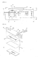
- FIG. 1 illustrates a top cross-sectional view of a cell separation system according to one embodiment of the present invention.
- the cell separation system consists essentially of a cartridge 10 and a base plate 50.
- the cartridge 10 has a polygonal shape in cross section and includes an injection part 20 and a separation chip 30. Blood, a sample bound with a functional additive for downstream separation and a buffer solution enter through the injection part 20.
- the injection part 20 has three inlet ports 21 and 22, as illustrated in FIG. 1 . Care should be taken to avoid the entrance of contaminants during injection.
- constant amounts of the blood, the functional additive, and the buffer solution should be always injected at constant flow rates.
- a sample loop 23 having a predetermined volume is interposed between the injection part 20 and the downstream separation chip 30 such that the amount and flow rate of the sample injected are maintained constant.
- the separation chip 30 is located downstream of the injection part 20 to separate cancer cells.
- the injection part 20 is interconnected to the separation chip 30 through the sample loop 23 or general channels.
- the separation chip 30 receives the sample and the buffer solution from the injection part 20 through two channels 31 and 32 connected to the injection part 20.
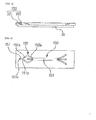
- FIG. 2 illustrates one embodiment of the separation chip 30 of the cell separation system according to the present invention.
- the separation chip 30 consists of a top plate, a first member, and a second member.
- the magnetic chip 35 is coupled to the bottom of the separation chip 30.
- the shape of the top plate 100 is similar to that of a thin rectangular plate.
- the first member 110 is similar to a plate whose thickness is smaller than its length and width.
- the top plate 100 is coupled to the first member 110.
- the second member 120 is interposed between the top plate 100 and the first member 110.
- the thickness of the second member 120 is designed to be smaller than the length and width thereof.
- the separation chip 30 of the cell separation system uses a double-sided adhesive tape as the second member 120. Accordingly, the top plate 100 is coupled to the first member 110 by an adhesive applied to the upper and lower surfaces of the second member 120.
- a plurality of holes are formed in the separation chip 30. Specifically, a hole 220a through which a sample solution is introduced and a hole 220b through which the buffer solution such as saline is introduced are formed at one side of the top plate 100. A hole 220c through which magnetic bead-bound cells are discharged and holes 220d and 220e through which other materials are discharged are formed at the other side of the top plate 100. The plurality of holes are in communication with the channels and pipes 170 are inserted into the holes.
- the magnetic chip 35 of the cell separation system is smaller in length and width than the separation chip 30, as illustrated in FIG. 1 .
- a wire-shaped magnetic chip pattern 200 is parabolic from one side to the other side of the magnetic chip 35. Specifically, the wire pattern 200 is located from the starting point of a third channel 153, one of the channels 150, where cells are separated, to the end point of the third channel 153. That is, the vertex of the parabolic wire pattern 200 is formed close to the end point of the third channel 153.
- the separation chip 30 of the cell separation system may be made of a plastic. Specifically, one or more of the top plate 100, the first member 110, and the second member 120 may be made of a plastic. Any plastic polymer may be used for the separation chip 30. Polycarbonate is preferred because its transparency and strength are above predetermined levels.
- each of the holes consists of a first portion 221 and a second portion 222.
- the first portion 221 has a relatively large diameter compared to the second portion 222.
- the number of the holes 220 formed when the top plate 100 is coupled to the second member 120 may vary depending on the total number of the introduction holes formed at one side of the separation chip 30 and the discharge holes formed at the other side of the separation chip 30.
- the rate of the solution introduced into a hole may be rather unstable.
- the channel may also be displaced when the separation chip is handled by an unskilled user.
- the separation chip 30 ensures stable introduction/flow of the solutions into/in the channels.
- the separation chip 30 is constructed such that the pipes 170 are inserted at acute angles to the upper surface 102 of the top plate.
- the holes 220a to 220e are inclined at acute angles to the upper surface 102 of the top plate.
- the pipes 170 inserted into the holes 220a to 220e also form acute angles to the upper surface 102 of the top plate.
- solutions are introduced into channels through syringes.
- the introduction holes are at right angles or substantially right angles to the syringes. The large angles relative to the injection lines lead to an increase in injection pressure, and as a result, smooth flows of the solutions are not ensured, increasing the probability of cell retention.
- the acute angles between the pipes inserted into the holes and the upper surface of the top plate lead to low flow resistance, and as a result, smooth flows of the solutions are ensured, decreasing the probability of cell retention and improving the durability of the chip.
- solutions are injected in the vertical direction through introduction holes or discharge holes.
- interference may be caused by tubes in communication with channels and made of a synthetic rubber such as PDMS.
- the use of the pipes in the cell separation system of the present invention and the connection of the pipes to the introduction holes and the discharge holes at acute angles rather than at right angles facilitate observation in the introduction holes 230 or the discharge holes 240 and prevent interference with the tubes 175 when a lens is focused on the introduction holes 230 or the discharge holes 240, enabling easy observation of the solution flows.
- FIG. 4 illustrates a first embodiment of the channels.
- a first channel 151 in communication with the introduction hole 220a is located in the middle of the top plate 100 in the widthwise direction of the top plate 100 and is formed at one side of the top plate 100 in the lengthwise direction of the top plate 100.
- One side 151a of the first channel may be in communication with the introduction hole 220a and the other side 151b of the first channel is in communication with a second channel 152.
- the second channel 152 includes a plurality of branched sub-channels.
- each of the branched sub-channels includes a first portion 152a and a second portion 152b.
- the first portion 152a of the branched sub-channel extends upward from the first channel 151 in the right direction and has a predetermined length.
- the second portion 152b of the branched sub-channel is in communication with the first portion 152a of the branched sub-channel.
- the second portion 152b of the branched sub-channel extends downward from the other side of the first portion 152a of the branched sub-channel and has a predetermined length.
- the first portion 152a of the branched sub-channel is widened toward the second portion 152b of the branched sub-channel.
- the second portion 152b of the branched sub-channel is tapered from the other side of the first portion 152a of the branched sub-channel toward a third channel 153 in communication with the second portion 152b of the branched sub-channel. That is, the portion of the branched sub-channel where the other side of the first portion 152a is connected to the one side of the second portion 152b is bent such that a flow of a solution is changed and is widened such that cells in the solution spread widely throughout the entire channel ("redistribution effect") based on the vortex flow.
- FIG. 5 illustrates a second embodiment of the channels of the separation chip 30 of the cell separation system.
- a first channel 151 in communication with the introduction hole 220a formed at one side of the top plate 100 is located in the middle of the top plate 100 in the widthwise direction of the top plate 100 and is formed at one side of the top plate 100 in the lengthwise direction of the top plate 100.
- the first channel 151 is smaller in length than a second channel 152 in communication with the first channel 151.
- the second channel 152 includes a plurality of branched sub-channels. As illustrated in FIGS. 5 and 6 , the second channel 152 may have an arc shape.
- the second channel 152 is located above and below the middle of the top plate 100 in the widthwise direction of the top plate 100 and may be branched into a plurality of sub-channels.
- the number of the branched sub-channels above the middle of the top plate 100 in the widthwise direction of the top plate 100 is at least two and the number of the branched sub-channels below the middle of the top plate 100 in the widthwise direction of the top plate 100 is at least two.
- FIG. 6 A third embodiment of the channels of the separation chip 30 of the cell separation system according to the present invention is illustrated in FIG. 6 .
- the separation chip 30 includes a plurality of branched sub-channels of a second channel 152 at one side of the top plate 100. Some of the branched sub-channels are combined into one before in communication with a third channel 153.
- the branched sub-channels are located above and below the middle of the top plate 100 in the widthwise direction of the top plate 100.
- the number of the branched sub-channels above the middle of the top plate 100 in the widthwise direction of the top plate 100 is two and the number of the branched sub-channels below the middle of the top plate 100 in the widthwise direction of the top plate 100 is two.
- the two branched sub-channels located above the middle of the top plate 100 in the widthwise direction of the top plate 100 are defined as a 2-1 st channel 1521 and a 2-2 nd channel 1522 and the two branched sub-channels located below the middle of the top plate 100 in the widthwise direction of the top plate 100 are defined as a 2-3 rd channel 1523 and a 2-4 th channel 1524.
- a portion of the 2-1 st channel 1521 and a portion of the 2-2 nd channel 1522 are combined to form one channel before in communication with the third channel 153.
- the portion 1521b of the 2-1 st channel 1521 is adjacent to the third channel 153 and the portion 1522b of the 2-2 nd channel 1522 is adjacent to the third channel 153.
- the portion 1521b of the 2-1 st channel and the portion 1522b of the 2-2 nd channel are combined into one and are in communication with the third channel 153.
- the separation chip 30 of the cell separation system may include filters located on the channels.
- a filter is located on the first channel 151 or the second channel 152 of the separation chip 30.
- the filter 180 may be provided in plurality on the second channel 152. Specifically, one filter 180 may be located on the first portion 152a of the second channel and one filter 180 may be located on the second portion 152b of the second channel. It should be understood that one or more filters 180 may also be located on the first channel 151.
- the filters 180 are in communication with the channels 150 and have predetermined spaces. In the cell separation system of the present invention, the filters serve to remove gases (air) present in a solution flowing in the channels.
- FIG. 7 The arrangement of the filters on the channels of the separation chip 30 of the cell separation system according to the present invention is illustrated in FIG. 7 .
- the filters 180 are located on the channels 150.
- protrusions 190 may be formed in the separation chip 30.
- the second channel 152 is in communication with the first channel 151 and is branched into a plurality of sub-channels. The protrusions 190 are formed on the first channel 151 or the second channel 152.
- the protrusions 190 are located on the second member 120 in which the channels 150 are formed.
- the channels 150 are formed by cutting off portions of the second member 120 along the shapes of the channels 150, which has been previously described.
- the protrusions 190 are formed on the channels 150 by cutting off portions other than the portions occupied by the protrusions 190 in the width direction of the channel 150.
- the protrusions 190 are slightly higher than the cut-off portions.
- the distances between the adjacent protrusions 190 are designed to be smaller than the size of air particles mixed in the solution. When the solution is introduced into the channels 150, the protrusions can prevent air particles mixed in the solution from flowing into the channels 150.
- the shape of the protrusions 190 is not limited as long as the protrusions 190 can filter air particles.
- the protrusions 190 may be rectangular, circular or diamond in shape.
- the protrusions 190 formed on the first channel 151 or the second channel 152 may also be arranged in one or more rows. That is, the protrusions 190 may include first protrusions A and second protrusions B underlying or adjacent to the first protrusions A, as illustrated in FIG. 8 .
- Cancer cells separated by the separation chip 30 and the magnetic chip 35 and blood free of cancer cells are accommodated in separate containers.
- the cancer cells and the blood are usually discharged through the simply connected channels.
- the use of the channels affects the internal pressure of each flow channel of the upstream separation unit. That is, when it is desired to separate cancer cells and a blood sample free of cancer cells, the rates and amounts of the substances flowing through the flow channels should be constant for accurate separation. If large amounts of the substances flow through some of the flow channels or the substances flow at high rates, the substances are concentrated on only the particular flow channels, causing errors in the separation of cancer cells. If the heights of the channels connected to external containers are not the same and the lengths of the channels are different, the rates and amounts of the substances flowing through the flow channels vary.
- the cell separation system of the present invention further includes a discharge part 40 ( FIG. 1 ), liquid sensors 60, and valves 70 provided downstream of the separation chip 30.
- the liquid sensors 60 and valves 70 serve to previously detect the inflow of air bubbles during discharge and adjust the flow of the substances.
- the important considerations in the spirit of the cell separation system according to the present invention are economic efficiency and convenience.
- the cell separation system is designed such that the cartridge 10 is separably coupled to the base plate 50 instead of integrating the two elements into one unit. Due to this design, disposable elements are distinguished from reusable elements. That is, the cartridge 10 of the cell separation system according to the present invention consists of the injection part 20, the separation chip 30, and the discharge part 40, which are disposable elements. In contrast, the magnetic chip 35 provided in the base plate 50 and the liquid sensors 60 and the valves 70 of the discharge part 40 are reusable elements. The cartridge 10 is coupled to the upper surface of the base plate 50.
- the liquid sensors 60 and the valves 70 located on the upper surface of the base plate 50 come into contact with the discharge channels formed on the lower surface of the cartridge 10, as illustrated in FIG. 9 . Due to this construction, the presence of air bubbles can be checked and the amounts of the substances flowing through the channels can be adjusted during discharge.
- the cartridge 10 is separably coupled to the base plate 50 after one-time use, as described above.
- the mechanism of separable coupling of these elements is important.
- the cell separation system of the present invention has a characteristic structure for coupling the cartridge 10 to the base plate 50.
- the cartridge 10 has a plane cut obliquely at a specific angle at one side thereof and has a recess 11 engaged with a pin 51 at the other side thereof, as illustrated in FIGS. 1 and 10 .
- the base plate 50 is adapted for the cartridge 10.
- the base plate 50 has a cut coupling plane 52 formed at one side thereof to press and fix the obliquely cut plane of the cartridge 10.
- the pin 51 is provided at the other side of the base plate 50 and is engaged with the recess 11 of the cartridge 10.A more detailed description will be given with reference to FIG. 10 .
- the coupling plane 52 formed at one side of the base plate 50 is connected from a position higher than an edge 12 of the cut plane of the cartridge 10 to a position lower than the edge 12 while in contact with the edge 12 so as to press the edge 12.
- the pin member 51 provided at the other side of the base plate 50 can be engaged with the recess 11 of the cartridge 10. Any pin member that can be connected to the recess 11 may be used.
- the pin is thrust when the recess 11 of the cartridge 10 is pushed toward the pin for engagement and is returned to its original position to again fix the recess.
- a side thrust pin is used that has a protrusion horizontally rotatable at full 360° and is capable of always returning to the central position.
- the cell separation system of the present invention uses inexpensive elements to construct the cartridge 10 and difficult-to-reuse elements to construct the base plate 50, as described above. Due to these constructions, the cartridge 10 is separated from the base plate 50 and is wasted after one-time use. Thereafter, a new cartridge 10 is coupled to the base plate 50. Accordingly, the new cartridge 10 should be accurately coupled to the base plate 50 for cancer cell separation. Specifically, the cancer cell flow channel formed in the separation chip 30 separating the sample flow channel of the cartridge 10 should accurately match the magnetic chip 35 provided in the base plate 50, and the liquid sensors 60 and the valves 70 provided on the base plate 50 should be coupled to each other such that the channels of the discharge part 40 provided in the cartridge 10 can be measured and controlled.
- the cell separation system of the present invention includes two technical features.
- both widthwise ends of the interface where the cartridge 10 is coupled to the base plate 50 are cut at the same angle to form planes 13 and 53.
- the formation of the cut planes enables accurate coupling between the cartridge 10 and the base plate 50.
- the planes 13 are formed by cutting both widthwise ends of one side of the cartridge 10 coupled to the base plate 50 at a predetermined angle and the planes 53 are formed by cutting both widthwise ends of the side of the base plate 50 facing the one side of the cartridge 10 at the same angle. Due to this feature, the cartridge 10 is engaged with the base plate 50.
- both ends of the cartridge 10 naturally and accurately match both ends of the base plate 50, enabling engagement of the cartridge 10 with the base plate 50.
- holes 33 and a pattern 34 formed on the separation chip 30 of the cartridge 10 match holes 201 and a pattern 202 formed on the magnetic chip 35 of the base plate 50.
- the separation chip 30 of the cartridge 10 has a polygonal shape in cross section, is patterned at a predetermined position, and includes holes 33 matching the magnetic chip 35 of the base plate 50 at one or more edges thereof.
- the magnetic chip 35 of the base plate 50 has a polygonal shape in cross section, is patterned at a predetermined position, and includes holes 201 matching the separation chip 30 of the cartridge 30 at one or more edges thereof.
- the distances between the magnetic chip 35 of the base plate 50 and the holes 201 and the pattern 202 formed in the magnetic chip are the same as those between the separation chip 30 of the cartridge 10 and the holes 33 and the pattern 34 formed in the separation chip.
- the holes 33 formed in the separation chip 30 of the cartridge 10 accurately match the holes 201 formed in the magnetic chip 35 of the base plate 50 such that the separation chip 30 and the magnetic chip 35 accurately match each other.
- a determination is made as to whether the pattern 34 formed in the separation chip 30 and the pattern 202 formed in the magnetic chip 35 match each other.
- the cartridge 10 and the base plate 50 have the same shape and the same number of the holes or the pattern on the cartridge 10 matches the pattern on the base plate 50.
- the present invention also provides a method for cell separation using the cell separation system.
- the method includes: fixing the separation chip 30 to the cell separation cartridge 10 and fixing the magnetic chip 35 to the base plate 50; coupling the cut plane of one side of the cell separation cartridge 10 to one side of the base plate 50; engaging the recess 11 formed at the other end of the cell separation cartridge 10 with the pin 51 formed at the other end of the base plate; confirming whether the holes 33 of the separation chip 30 of the cartridge 10 match the holes 201 of the magnetic chip 35 of the base plate 50; and confirming whether the pattern 34 of the separation chip 30 of the cartridge 10 matches the pattern 202 of the magnetic chip 35 of the base plate 50.
Landscapes
- Chemical & Material Sciences (AREA)
- Health & Medical Sciences (AREA)
- General Health & Medical Sciences (AREA)
- Analytical Chemistry (AREA)
- Dispersion Chemistry (AREA)
- Physics & Mathematics (AREA)
- Immunology (AREA)
- General Physics & Mathematics (AREA)
- Biochemistry (AREA)
- Life Sciences & Earth Sciences (AREA)
- Pathology (AREA)
- Hematology (AREA)
- Clinical Laboratory Science (AREA)
- Chemical Kinetics & Catalysis (AREA)
- Apparatus Associated With Microorganisms And Enzymes (AREA)
- Fluid Mechanics (AREA)
Description
- The present invention relates to a system and method for cell separation. More specifically, the present invention relates to a system for cell separation in which an injection part and a separation part necessary for cell separation are provided on the same cartridge so that they can be coupled to and separated from each other by one-time operation and accurate coupling of the cell separation cartridge to a base plate can be easily checked, and a method for cell separation using the system.
- 27.9% of all deaths in Korea in 2015 resulted from cancer and the number thereof was 76,855. Cancer deaths are rising steadily every year. Lung cancer was the leading cause of cancer death in Korea and its rate was 17,399 in 2015. The rates of liver cancer, gastric cancer, and pancreatic cancer in both Korean men and women increase in this order. Most of these cancer patients do not die of their primary tumors but of metastases of a broad range of multiple tumor colonies formed by malignant cells that are separated from initial tumors and often migrate to distal sites through blood. Primary tumors detected in the initial stage can be removed by surgery, radiotherapy or chemotherapy but cancer cells circulating in the bloodstream are present at very low concentrations that are difficult to detect. For this reason, the likelihood of success of initial detection of cancer cells in blood is substantially low. Cancer cells in blood refer collectively to cancer cells present in the peripheral blood of cancer patients and are defined as cancer cells that fall off from primary or metastatic lesions. In recent years, approaches have been developed to use cancer cells in blood as potent biomarkers for cancer diagnosis, analysis of therapeutic prognosis, and analysis of micrometastasis. As described above, a very low concentration of cancer cells is distributed in blood. For example, one cancer cell is present per billion normal cells or one to ten million leukocytes in blood. Cancer cells are difficult to accurately analyze due to the presence of interfering factors such as contaminants and air bubbles during analysis. In addition, systems for separating cancer cells from blood are still relatively expensive given that the number of cancer patients is rapidly increasing every year. Most of such systems are disposable and are discarded after use. In addition to this economic burden, the systems are complicated to install.
- Specifically, a method for separating cancer cells from blood involves three steps, i.e. blood sample production, sample injection, and cancer cell separation. The blood sample is prepared by mixing and binding blood, an antibody reacting specifically with cancer cells, and a functional material for downstream cancer cell separation such as a magnetic material. Then, the blood sample is injected into a system for cancer cell separation. It is important to inject an accurate amount of the blood sample at a constant flow rate while precluding the entrance of interfering factors, such as contaminants and air bubbles. The magnetic material previously bound to the blood is used as a carrier for cancer cell separation. The system usually includes a plurality of divided flow channels for cancer cells and non-cancer cells. It is important to secure accurate separation of cancer cells by maintaining the flow rates of the substances flowing through the flow channels at constant levels.
- Many technologies for cancer cell separation have been investigated so far. Patent Document 1 relates to a method and reagent for rapidly and effectively separating circulating cancer cells and proposes a technique for separating cancer cells from a mixture of blood collected from a patent and a ligand (the can be detected due to its specific reaction with cancer cells). However, this patent document fails to consider the problems of contamination during injection of the blood sample and inaccurate separation of cancer cells. Patent Document 2 proposes a technique for separating cancer cells using ferromagnetic wires. However, this patent document fails to consider technical details for securing preset values for flow channels during discharge and the same amount and rate of substances flowing through the flow channels. Particularly, channels are usually used to accommodate separated cancer cells in a given container. At this time, the flow rate of the cancer cells in each flow channel may vary depending on the length and height of the channel, causing poor separation accuracy.
- Further, Patent Document 3 discloses a microparticle analysis device including a micro-fluidic chip configured to have a region into which a sample liquid containing a magnetic microparticle and a non-magnetic microparticle is introduced, and a microfluidic channel communicating with the region on a downstream side in a liquid sending direction, a magnetic field generating section configured to form a magnetic field in an internal space of the region, and a detecting section configured to detect an optical, electrical, or magnetic characteristic of a microparticle passing through the microfluidic channel. Patent Document 4 relates to a system and method for processing and detecting nucleic acids from a set of biological samples. The system comprises a capture plate and a capture plate module configured to facilitate binding of nucleic acids within the set of biological samples to magnetic beads, a molecular diagnostic module configured to receive nucleic acids bound to magnetic beads, isolate nucleic acids, and analyze nucleic acids, comprising a cartridge receiving module, a heating/cooling subsystem and a magnet configured to facilitate isolation of nucleic acids, a valve actuation subsystem configured to control fluid flow through a microfluidic cartridge for processing nucleic acids, and an optical subsystem for analysis of nucleic acids, a fluid handling system configured to deliver samples and reagents to components of the system to facilitate molecular diagnostic protocols, and an assay strip configured to combine nucleic acid samples with molecular diagnostic reagents for analysis of nucleic acids. Patent Document 5 proposes a cartridge for a magnetic flow cytometer, mainly extending in a x-y-plane, with an inlet for injecting a sample into the cartridge, a blister for a buffer solution with magnetic markers to mark pregiven particles of the sample, an outlet, and a fluid channel. The fluid channel comprises a first part that connects the inlet with the blister and a second part that connects the first part with the outlet, wherein the second part of the fluid channel comprises an enrichment zone with mechanical guiding structures to focus marked particles of the sample in a predetermined subsection of the fluid channel and a measuring zone between the enrichment zone and the outlet. The measuring zone comprising a magnetic field sensor in the predetermined subsection of the fluid channel in order to provide simplified and accelerated means for measuring particles, in particular concentrations of particles, of a sample. Patent Document 6 relates to a device for detecting an analyte in a sample. The device comprises a fluidic network and an integrated circuitry component. The fluidic network comprises a sample zone, a cleaning zone and a detection zone. The fluidic network contains a magnetic particle and/or a signal particle. A sample containing an analyte is introduced, and the analyte interacts with the magnetic particle and/or the signal particle through affinity agents. A microcoil array or a mechanically movable permanent magnet is functionally coupled to the fluidic network, which are activatable to generate a magnetic field within a portion of the fluidic network, and move the magnetic particle from the sample zone to the detection zone. A detection element is present which detects optical or electrical signals from the signal particle, thus indicating the presence of the analyte.
-
- 1: International Patent Publication
WO 2003/065042 - 2:
Korean Patent Publication No. 2015-0058955 - 3:
European Patent Publication EP 2 191 895 A1 - 4: US Patent Publication
US 2015/151300 A1 - 5:
International Patent Publication WO 2015/176744 A1 - 6: US Patent Publication
US 2012/322683 A1 - The present invention has been made in an effort to solve the problems of the prior art, and one object of the present invention is to secure high accuracy of blood sample injection and cell separation by minimizing the entrance of contaminants
- A further object of the present invention is to provide a system for cell separation in which expensive or easy-to-recycle members are provided on the same cartridge or base plate so that they can be coupled to and separated from each other by one-time operation.
- Another object of the present invention is to provide a system for cell separation in which accurate coupling between a cartridge and a base plate is previously checked to secure accurate cell separation when the cartridge is replaced with a new one.
- A cell separation system according to one aspect of the present invention includes: a cartridge having a polygonal shape in cross section and including an injection part, a separation chip separating a flow channel of a sample injected through the injection part and being located downstream of the injection part to separate cancer cells, and a discharge part; and a base plate coupled to the cartridge through its upper surface and including a magnetic chip for cancer cell capture, wherein the separation chip of the cartridge is separably coupled to the magnetic chip of the base plate, liquid sensors, and valves.
- The discharge part, the liquid sensors, and the valves are provided downstream of the separation chip and the liquid sensors and the valves are located on an upper surface of the base plate to come into contact with discharge channels formed on a lower surface of the cartridge and serve to previously detect the inflow of air bubbles during discharge and adjust the flow of substances.
- The channels of the discharge part of the cartridge are in contact with the liquid sensors and the valves when the cartridge is coupled to the base plate.
- The separation chip includes a top plate having holes into which pipes are insertable, each hole including a first portion having a larger diameter and a second portion having a smaller diameter. The separation chip includes a second member coupled to the top plate through a tape applied to the upper surface thereof and a first member located under the second member and coupled to the lower surface of the second member through a tape applied to the lower surface of the second member. Portions of the second member are cut-off to form channels in the second member, the holes are formed so as to penetrate through the upper and lower surfaces of the top plate and to be in communication with the channels, and the pipes are inserted into the first portions of the holes at acute angles to the upper surface of the top plate.
- Preferably, in the cell separation system of the present invention, the magnetic chip includes a wire pattern that is parabolic from one side to the other side thereof.
- Preferably, the top plate of the separation chip of the cell separation system according to the present invention is made of a plastic.
- Preferably, the channels of the cell separation system according to the present invention include a first channel and a second channel in communication with the first channel and branched into a plurality of sub-channels, each of which includes a first portion and a second portion in communication with the first portion, the first portion being widened toward the second portion and the second portion being tapered toward a third channel in communication with the second channel.
- Preferably, the channels of the cell separation system according to the present invention include a first channel and a second channel in communication with the first channel, branched into a plurality of sub-channels, and having an arc shape.
- Preferably, the channels of the cell separation system according to the present invention include a first channel and a second channel in communication with the first channel and branched into a plurality of sub-channels, a plurality of protrusions being formed on the first channel or the second channel.
- Preferably, the protrusions include first protrusions and second protrusions underlying or adjacent to the first protrusions.
- Preferably, in the cell separation system of the present invention, filters are located on and in communication with the channels and have predetermined spaces.
- Preferably, in the cell separation system of the present invention, the cell separation cartridge has a plane cut at a specific angle at one side thereof, the edge of the cut plane is higher than the lower surface of the cartridge, and the cartridge has a recess engaged with a pin at the other side thereof. The base plate has a plane formed at one side thereof to press the edge of the cut plane of the cartridge while in contact with the edge of the cut plane of the cartridge and connected from a position higher than the edge of the cut plane of the cartridge to a position lower than the edge, and includes a pin member provided at the other side thereof and engaged with the recess of the cartridge.
- The pin member has the ability to always return to the central position and includes a protrusion horizontally rotatable at full 360°, both end edges of the coupling plane of the cartridge at one side where the cartridge is coupled to the base plate are cut at a predetermined angle, and both end edges of the coupling plane of the base plate facing the coupling plane of the cartridge are cut at the same angle such that both end edges of the coupling plane of the cartridge match and are coupled to the both end edges of the coupling plane of the base plate.
- The separation chip of the cartridge of the cell separation system according to the present invention has a polygonal shape in cross section is patterned at a predetermined position and includes holes matching the magnetic chip of the base plate at one or more edges thereof. The magnetic chip of the base plate has a polygonal shape in cross section, is patterned at a predetermined position, and includes holes matching the separation chip of the cartridge at one or more edges thereof. The distances between the magnetic chip of the base plate and the holes and the pattern formed in the magnetic chip are the same as those between the separation chip of the cartridge and the holes and the pattern formed in the separation chip. Here, the base plate and the cartridge have the same shape and the same number of the holes or the pattern on the cartridge matches the pattern on the base plate.
- A method for cell separation according to a further aspect of the present invention uses the cell separation system. Specifically, the method includes: fixing the separation chip to the cell separation cartridge and fixing the magnetic chip to the base plate; coupling the cut plane of one side of the cell separation cartridge to one side of the base plate; engaging the recess formed at the other end of the cell separation cartridge with the pin formed at the other end of the base plate; and confirming whether the holes of the separation chip of the cartridge match the holes of the magnetic chip of the base plate.
- In the system and method for cell separation according to the present invention, the injection part and the separation part necessary for cell separation are provided on the same cartridge so that they can be coupled to and separated from each other by one-time operation and accurate coupling of the setting can be checked.
- In addition, a group of easy-to-replace members and a group of difficult-to-replace members are separately provided on the same cartridge or plate. This construction is effective in improving the reuse efficiency of the cell separation system.
- Particularly, the separation chip of the cell separation system according to the present invention is made of a plastic that can be wasted after completion of examination. Therefore, the separation chip does not need to be washed. The separation chip can be produced by a relatively simple technique rather than by a semiconductor technique or MEMS technique, which contributes to production cost saving. In addition, the separation chip can be produced on a large scale, securing economic efficiency while ensuring constant quality.
-
-
FIG. 1 is a top cross-sectional view of a cell separation system according to one embodiment of the present invention. -
FIG. 2 illustrates a first embodiment of aseparation chip 30 according to one embodiment of the present invention. -
FIG. 3 illustrates the construction of holes of aseparation chip 30 according to one embodiment of the present invention. -
FIG. 4 illustrates a first embodiment of channels of aseparation chip 30 according to one embodiment of the present invention. -
FIG. 5 illustrates a second embodiment of channels of aseparation chip 30 according to one embodiment of the present invention. -
FIG. 6 illustrates a third embodiment of channels of aseparation chip 30 according to one embodiment of the present invention. -
FIG. 7 illustrates the locations of filters on channels of aseparation chip 30 according to one embodiment of the present invention. -
FIG. 8 illustrates the construction of filters of aseparation chip 30 according to one embodiment of the present invention. -
FIG. 9 is a top cross-sectional view of a base plate according to one embodiment of the present invention. -
FIG. 10 is a cross-sectional view illustrating an arrangement in which a cell separation cartridge and a base plate are fixed to each other according to one embodiment of the present invention. -
FIG. 11 illustrates a structure in which a cell separation cartridge is fixed to a base plate according to one embodiment of the present invention. -
FIG. 12 illustrates a structure in which aseparation chip 30 on a cartridge is coupled to a magnetic chip on a base plate. - A system and method for cell separation according to the present invention will now be described with reference to the accompanying drawings.
- In the present application, it is to be understood that the terms such as "including" or "having," etc., are intended to indicate the existence of the features, numbers, steps, elements, parts, or combinations thereof disclosed in the specification, and are not intended to preclude the possibility that one or more other features, numbers, steps, elements, parts, or combinations thereof may exist or may be added.
- Unless otherwise defined, all terms used herein, including technical or scientific terms, have the same meanings as those generally understood by those with ordinary knowledge in the field of art to which the present invention belongs. Such terms as those defined in a generally used dictionary are to be interpreted to have the meanings equal to the contextual meanings in the relevant field of art, and are not to be interpreted to have ideal or excessively formal meanings unless clearly defined in the present application.
-
FIG. 1 illustrates a top cross-sectional view of a cell separation system according to one embodiment of the present invention. Referring toFIG. 1 , the cell separation system consists essentially of acartridge 10 and abase plate 50. Thecartridge 10 has a polygonal shape in cross section and includes aninjection part 20 and aseparation chip 30. Blood, a sample bound with a functional additive for downstream separation and a buffer solution enter through theinjection part 20. To this end, theinjection part 20 has threeinlet ports FIG. 1 . Care should be taken to avoid the entrance of contaminants during injection. In addition, constant amounts of the blood, the functional additive, and the buffer solution should be always injected at constant flow rates. The entrance of an interfering substance other than the blood, the functional additive, and the buffer solution may produce errors in subsequent analysis. As described above, since only a very small amount of cancer cells is present in blood, the entrance of a small amount of an interfering substance may cause significant errors in analysis results. Changes in the flow rates or the amounts of the substances injected may lead to changes in the rates of the substances flowing through flow channels in a downstream separation step, increasing the possibility of errors during separation. Thus, as illustrated inFIG. 1 , asample loop 23 having a predetermined volume is interposed between theinjection part 20 and thedownstream separation chip 30 such that the amount and flow rate of the sample injected are maintained constant. In the cell separation system, theseparation chip 30 is located downstream of theinjection part 20 to separate cancer cells. Theinjection part 20 is interconnected to theseparation chip 30 through thesample loop 23 or general channels. Theseparation chip 30 receives the sample and the buffer solution from theinjection part 20 through twochannels injection part 20. - In the present invention, a magnetic material bound to an antibody reacting specifically with cancer cells is used to separate the cancer cells. Cancer cells in blood are bound to the magnetic material during mixing with the blood. To this end, the
separation chip 30 of thecartridge 10 is separably coupled to amagnetic chip 35 of thebase plate 50. Due to this construction, theseparation chip 30 made of a plastic can be wasted after one-time use.FIG. 2 illustrates one embodiment of theseparation chip 30 of the cell separation system according to the present invention. Referring toFIG. 2 , theseparation chip 30 consists of a top plate, a first member, and a second member. Themagnetic chip 35 is coupled to the bottom of theseparation chip 30. - First, the construction of the
separation chip 30 will be discussed. The shape of thetop plate 100 is similar to that of a thin rectangular plate. Thefirst member 110 is similar to a plate whose thickness is smaller than its length and width. Thetop plate 100 is coupled to thefirst member 110. Here, thesecond member 120 is interposed between thetop plate 100 and thefirst member 110. The thickness of thesecond member 120 is designed to be smaller than the length and width thereof. Theseparation chip 30 of the cell separation system uses a double-sided adhesive tape as thesecond member 120. Accordingly, thetop plate 100 is coupled to thefirst member 110 by an adhesive applied to the upper and lower surfaces of thesecond member 120. - A plurality of holes are formed in the
separation chip 30. Specifically, ahole 220a through which a sample solution is introduced and ahole 220b through which the buffer solution such as saline is introduced are formed at one side of thetop plate 100. Ahole 220c through which magnetic bead-bound cells are discharged andholes top plate 100. The plurality of holes are in communication with the channels andpipes 170 are inserted into the holes. - The
magnetic chip 35 of the cell separation system is smaller in length and width than theseparation chip 30, as illustrated inFIG. 1 . A wire-shapedmagnetic chip pattern 200 is parabolic from one side to the other side of themagnetic chip 35. Specifically, thewire pattern 200 is located from the starting point of athird channel 153, one of thechannels 150, where cells are separated, to the end point of thethird channel 153. That is, the vertex of theparabolic wire pattern 200 is formed close to the end point of thethird channel 153. - The
separation chip 30 of the cell separation system may be made of a plastic. Specifically, one or more of thetop plate 100, thefirst member 110, and thesecond member 120 may be made of a plastic. Any plastic polymer may be used for theseparation chip 30. Polycarbonate is preferred because its transparency and strength are above predetermined levels. - Unlike in the prior art, the channels are not directly connected to the
separation chip 30 of the cell separation system but are connected to theseparation chip 30 of the cell separation system through the pipes, as described above. For these connections, the diameters of the holes 220 formed in thetop plate 100 and in communication with thechannels 150 vary depending on the lengths of the channels.FIG. 3 illustrates the construction of the holes of theseparation chip 30 of the cell separation system. Referring toFIG. 3 , each of the holes consists of a first portion 221 and a second portion 222. The first portion 221 has a relatively large diameter compared to the second portion 222. With these dimensions, thepipes 170 can be inserted into the corresponding holes. The number of the holes 220 formed when thetop plate 100 is coupled to thesecond member 120 may vary depending on the total number of the introduction holes formed at one side of theseparation chip 30 and the discharge holes formed at the other side of theseparation chip 30. When a solution is directly introduced into a channel without using a pipe, as in the prior art, the rate of the solution introduced into a hole may be rather unstable. The channel may also be displaced when the separation chip is handled by an unskilled user. In contrast, since thepipes 170 are inserted into theholes 220a to 220e and solutions flow fromtubes 175 into thechannels 150 via thepipes 170, theseparation chip 30 ensures stable introduction/flow of the solutions into/in the channels. - The
separation chip 30 is constructed such that thepipes 170 are inserted at acute angles to theupper surface 102 of the top plate. For this construction, theholes 220a to 220e are inclined at acute angles to theupper surface 102 of the top plate. In this case, thepipes 170 inserted into theholes 220a to 220e also form acute angles to theupper surface 102 of the top plate. According to the prior art, solutions are introduced into channels through syringes. In this case, the introduction holes are at right angles or substantially right angles to the syringes. The large angles relative to the injection lines lead to an increase in injection pressure, and as a result, smooth flows of the solutions are not ensured, increasing the probability of cell retention. In contrast, according to the cell separation system of the present invention, the acute angles between the pipes inserted into the holes and the upper surface of the top plate lead to low flow resistance, and as a result, smooth flows of the solutions are ensured, decreasing the probability of cell retention and improving the durability of the chip. According to the prior art, solutions are injected in the vertical direction through introduction holes or discharge holes. In this case, when a lens moves for close observation of the introduction holes or the discharge holes, interference may be caused by tubes in communication with channels and made of a synthetic rubber such as PDMS. In contrast, the use of the pipes in the cell separation system of the present invention and the connection of the pipes to the introduction holes and the discharge holes at acute angles rather than at right angles facilitate observation in the introduction holes 230 or the discharge holes 240 and prevent interference with thetubes 175 when a lens is focused on the introduction holes 230 or the discharge holes 240, enabling easy observation of the solution flows. - In the
separation chip 30 of the cell separation system, the channels may be embodied in various different forms.FIG. 4 illustrates a first embodiment of the channels. Referring toFIG. 4 , afirst channel 151 in communication with theintroduction hole 220a is located in the middle of thetop plate 100 in the widthwise direction of thetop plate 100 and is formed at one side of thetop plate 100 in the lengthwise direction of thetop plate 100. Oneside 151a of the first channel may be in communication with theintroduction hole 220a and theother side 151b of the first channel is in communication with asecond channel 152. Thesecond channel 152 includes a plurality of branched sub-channels. The following description will be given mainly on the overlying branched sub-channels in the widthwise direction of thetop plate 100. First, each of the branched sub-channels includes afirst portion 152a and asecond portion 152b. Thefirst portion 152a of the branched sub-channel extends upward from thefirst channel 151 in the right direction and has a predetermined length. Thesecond portion 152b of the branched sub-channel is in communication with thefirst portion 152a of the branched sub-channel. Thesecond portion 152b of the branched sub-channel extends downward from the other side of thefirst portion 152a of the branched sub-channel and has a predetermined length. Thefirst portion 152a of the branched sub-channel is widened toward thesecond portion 152b of the branched sub-channel. In contrast, thesecond portion 152b of the branched sub-channel is tapered from the other side of thefirst portion 152a of the branched sub-channel toward athird channel 153 in communication with thesecond portion 152b of the branched sub-channel. That is, the portion of the branched sub-channel where the other side of thefirst portion 152a is connected to the one side of thesecond portion 152b is bent such that a flow of a solution is changed and is widened such that cells in the solution spread widely throughout the entire channel ("redistribution effect") based on the vortex flow. If the width of the branched sub-channel is maintained constant, cells flow along only one wall of the channel after passage through the bent portion where the other side of thefirst portion 152a of the branched sub-channel is connected to the one side of thesecond portion 152b.FIG. 5 illustrates a second embodiment of the channels of theseparation chip 30 of the cell separation system. As well illustrated inFIG. 5 , afirst channel 151 in communication with theintroduction hole 220a formed at one side of thetop plate 100 is located in the middle of thetop plate 100 in the widthwise direction of thetop plate 100 and is formed at one side of thetop plate 100 in the lengthwise direction of thetop plate 100. For reference, thefirst channel 151 is smaller in length than asecond channel 152 in communication with thefirst channel 151. Thesecond channel 152 includes a plurality of branched sub-channels. As illustrated inFIGS. 5 and 6 , thesecond channel 152 may have an arc shape. Thesecond channel 152 is located above and below the middle of thetop plate 100 in the widthwise direction of thetop plate 100 and may be branched into a plurality of sub-channels. The number of the branched sub-channels above the middle of thetop plate 100 in the widthwise direction of thetop plate 100 is at least two and the number of the branched sub-channels below the middle of thetop plate 100 in the widthwise direction of thetop plate 100 is at least two. - A third embodiment of the channels of the
separation chip 30 of the cell separation system according to the present invention is illustrated inFIG. 6 . Theseparation chip 30 includes a plurality of branched sub-channels of asecond channel 152 at one side of thetop plate 100. Some of the branched sub-channels are combined into one before in communication with athird channel 153. The branched sub-channels are located above and below the middle of thetop plate 100 in the widthwise direction of thetop plate 100. The number of the branched sub-channels above the middle of thetop plate 100 in the widthwise direction of thetop plate 100 is two and the number of the branched sub-channels below the middle of thetop plate 100 in the widthwise direction of thetop plate 100 is two. In the following description, the two branched sub-channels located above the middle of thetop plate 100 in the widthwise direction of thetop plate 100 are defined as a 2-1stchannel 1521 and a 2-2ndchannel 1522 and the two branched sub-channels located below the middle of thetop plate 100 in the widthwise direction of thetop plate 100 are defined as a 2-3rdchannel 1523 and a 2-4thchannel 1524. A portion of the 2-1stchannel 1521 and a portion of the 2-2ndchannel 1522 are combined to form one channel before in communication with thethird channel 153. Specifically, theportion 1521b of the 2-1stchannel 1521 is adjacent to thethird channel 153 and theportion 1522b of the 2-2ndchannel 1522 is adjacent to thethird channel 153. Theportion 1521b of the 2-1st channel and theportion 1522b of the 2-2nd channel are combined into one and are in communication with thethird channel 153. - The
separation chip 30 of the cell separation system according to the present invention may include filters located on the channels. Referring toFIG. 7 , a filter is located on thefirst channel 151 or thesecond channel 152 of theseparation chip 30. Thefilter 180 may be provided in plurality on thesecond channel 152. Specifically, onefilter 180 may be located on thefirst portion 152a of the second channel and onefilter 180 may be located on thesecond portion 152b of the second channel. It should be understood that one ormore filters 180 may also be located on thefirst channel 151. Thefilters 180 are in communication with thechannels 150 and have predetermined spaces. In the cell separation system of the present invention, the filters serve to remove gases (air) present in a solution flowing in the channels. When a gas-containing solution passes through thefilters 180, the gases float above the solution due to their different specific gravities. The gases are confined in the spaces of thefilters 180 in communication with thechannels 150. The collected gases are removed from the solution.The arrangement of the filters on the channels of theseparation chip 30 of the cell separation system according to the present invention is illustrated inFIG. 7 . As illustrated inFIG. 7 , thefilters 180 are located on thechannels 150. As illustrated inFIG. 8 ,protrusions 190 may be formed in theseparation chip 30. As illustrated inFIG. 7 , thesecond channel 152 is in communication with thefirst channel 151 and is branched into a plurality of sub-channels. Theprotrusions 190 are formed on thefirst channel 151 or thesecond channel 152. Theprotrusions 190 are located on thesecond member 120 in which thechannels 150 are formed. Thechannels 150 are formed by cutting off portions of thesecond member 120 along the shapes of thechannels 150, which has been previously described. Here, theprotrusions 190 are formed on thechannels 150 by cutting off portions other than the portions occupied by theprotrusions 190 in the width direction of thechannel 150. Theprotrusions 190 are slightly higher than the cut-off portions. The distances between theadjacent protrusions 190 are designed to be smaller than the size of air particles mixed in the solution. When the solution is introduced into thechannels 150, the protrusions can prevent air particles mixed in the solution from flowing into thechannels 150. The shape of theprotrusions 190 is not limited as long as theprotrusions 190 can filter air particles. For example, theprotrusions 190 may be rectangular, circular or diamond in shape. Theprotrusions 190 formed on thefirst channel 151 or thesecond channel 152 may also be arranged in one or more rows. That is, theprotrusions 190 may include first protrusions A and second protrusions B underlying or adjacent to the first protrusions A, as illustrated inFIG. 8 . - Cancer cells separated by the
separation chip 30 and themagnetic chip 35 and blood free of cancer cells are accommodated in separate containers. In this course, the cancer cells and the blood are usually discharged through the simply connected channels. However, the use of the channels affects the internal pressure of each flow channel of the upstream separation unit. That is, when it is desired to separate cancer cells and a blood sample free of cancer cells, the rates and amounts of the substances flowing through the flow channels should be constant for accurate separation. If large amounts of the substances flow through some of the flow channels or the substances flow at high rates, the substances are concentrated on only the particular flow channels, causing errors in the separation of cancer cells. If the heights of the channels connected to external containers are not the same and the lengths of the channels are different, the rates and amounts of the substances flowing through the flow channels vary. To solve these problems, the cell separation system of the present invention further includes a discharge part 40 (FIG. 1 ),liquid sensors 60, andvalves 70 provided downstream of theseparation chip 30. Theliquid sensors 60 andvalves 70 serve to previously detect the inflow of air bubbles during discharge and adjust the flow of the substances. - The important considerations in the spirit of the cell separation system according to the present invention are economic efficiency and convenience. The cell separation system is designed such that the
cartridge 10 is separably coupled to thebase plate 50 instead of integrating the two elements into one unit. Due to this design, disposable elements are distinguished from reusable elements. That is, thecartridge 10 of the cell separation system according to the present invention consists of theinjection part 20, theseparation chip 30, and thedischarge part 40, which are disposable elements. In contrast, themagnetic chip 35 provided in thebase plate 50 and theliquid sensors 60 and thevalves 70 of thedischarge part 40 are reusable elements. Thecartridge 10 is coupled to the upper surface of thebase plate 50. Here, theliquid sensors 60 and thevalves 70 located on the upper surface of thebase plate 50 come into contact with the discharge channels formed on the lower surface of thecartridge 10, as illustrated inFIG. 9 . Due to this construction, the presence of air bubbles can be checked and the amounts of the substances flowing through the channels can be adjusted during discharge. - In the cell separation system of the present invention, the
cartridge 10 is separably coupled to thebase plate 50 after one-time use, as described above. Thus, the mechanism of separable coupling of these elements is important. To this end, the cell separation system of the present invention has a characteristic structure for coupling thecartridge 10 to thebase plate 50. First, thecartridge 10 has a plane cut obliquely at a specific angle at one side thereof and has arecess 11 engaged with apin 51 at the other side thereof, as illustrated inFIGS. 1 and10 . Thebase plate 50 is adapted for thecartridge 10. Thebase plate 50 has acut coupling plane 52 formed at one side thereof to press and fix the obliquely cut plane of thecartridge 10. Thepin 51 is provided at the other side of thebase plate 50 and is engaged with therecess 11 of the cartridge 10.A more detailed description will be given with reference toFIG. 10 . Thecoupling plane 52 formed at one side of thebase plate 50 is connected from a position higher than anedge 12 of the cut plane of thecartridge 10 to a position lower than theedge 12 while in contact with theedge 12 so as to press theedge 12. Thepin member 51 provided at the other side of thebase plate 50 can be engaged with therecess 11 of thecartridge 10. Any pin member that can be connected to therecess 11 may be used. Preferably, the pin is thrust when therecess 11 of thecartridge 10 is pushed toward the pin for engagement and is returned to its original position to again fix the recess. Accordingly, in one embodiment of the present invention, a side thrust pin is used that has a protrusion horizontally rotatable at full 360° and is capable of always returning to the central position. - The cell separation system of the present invention uses inexpensive elements to construct the
cartridge 10 and difficult-to-reuse elements to construct thebase plate 50, as described above. Due to these constructions, thecartridge 10 is separated from thebase plate 50 and is wasted after one-time use. Thereafter, anew cartridge 10 is coupled to thebase plate 50. Accordingly, thenew cartridge 10 should be accurately coupled to thebase plate 50 for cancer cell separation. Specifically, the cancer cell flow channel formed in theseparation chip 30 separating the sample flow channel of thecartridge 10 should accurately match themagnetic chip 35 provided in thebase plate 50, and theliquid sensors 60 and thevalves 70 provided on thebase plate 50 should be coupled to each other such that the channels of thedischarge part 40 provided in thecartridge 10 can be measured and controlled. To accurately implement this, the cell separation system of the present invention includes two technical features. According to the first feature, both widthwise ends of the interface where thecartridge 10 is coupled to thebase plate 50 are cut at the same angle to formplanes cartridge 10 and thebase plate 50. This feature will be described in detail with reference toFIG. 11 . Theplanes 13 are formed by cutting both widthwise ends of one side of thecartridge 10 coupled to thebase plate 50 at a predetermined angle and theplanes 53 are formed by cutting both widthwise ends of the side of thebase plate 50 facing the one side of thecartridge 10 at the same angle. Due to this feature, thecartridge 10 is engaged with thebase plate 50. When thecartridge 10 and thebase plate 50 are cut at the same angle, both ends of thecartridge 10 naturally and accurately match both ends of thebase plate 50, enabling engagement of thecartridge 10 with thebase plate 50. - According to the second feature, holes 33 and a
pattern 34 formed on theseparation chip 30 of thecartridge 10 match holes 201 and apattern 202 formed on themagnetic chip 35 of thebase plate 50. Referring toFIG. 12 , theseparation chip 30 of thecartridge 10 has a polygonal shape in cross section, is patterned at a predetermined position, and includes holes 33 matching themagnetic chip 35 of thebase plate 50 at one or more edges thereof. Themagnetic chip 35 of thebase plate 50 has a polygonal shape in cross section, is patterned at a predetermined position, and includes holes 201 matching theseparation chip 30 of thecartridge 30 at one or more edges thereof. The distances between themagnetic chip 35 of thebase plate 50 and the holes 201 and thepattern 202 formed in the magnetic chip are the same as those between theseparation chip 30 of thecartridge 10 and the holes 33 and thepattern 34 formed in the separation chip. Thus, when thecartridge 10 is coupled to thebase plate 50, the holes 33 formed in theseparation chip 30 of thecartridge 10 accurately match the holes 201 formed in themagnetic chip 35 of thebase plate 50 such that theseparation chip 30 and themagnetic chip 35 accurately match each other. To confirm whether theseparation chip 30 accurately matches themagnetic chip 35 after coupling of thecartridge 10 to thebase plate 50, a determination is made as to whether thepattern 34 formed in theseparation chip 30 and thepattern 202 formed in themagnetic chip 35 match each other. To this end, it is preferred that thecartridge 10 and thebase plate 50 have the same shape and the same number of the holes or the pattern on thecartridge 10 matches the pattern on thebase plate 50. - The present invention also provides a method for cell separation using the cell separation system. The method includes: fixing the
separation chip 30 to thecell separation cartridge 10 and fixing themagnetic chip 35 to thebase plate 50; coupling the cut plane of one side of thecell separation cartridge 10 to one side of thebase plate 50; engaging therecess 11 formed at the other end of thecell separation cartridge 10 with thepin 51 formed at the other end of the base plate; confirming whether the holes 33 of theseparation chip 30 of thecartridge 10 match the holes 201 of themagnetic chip 35 of thebase plate 50; and confirming whether thepattern 34 of theseparation chip 30 of thecartridge 10 matches thepattern 202 of themagnetic chip 35 of thebase plate 50. - Although the particulars of the present disclosure have been described in detail, it will be obvious to those skilled in the art that such particulars are merely preferred embodiments and are not intended to limit the scope of the present disclosure; the invention being defined by the appended claims.
Claims (12)
- A cell separation system comprising: a cartridge (10) having a polygonal shape in cross section and comprising an injection part (20), a separation chip (30) separating a flow channel of a sample injected through the injection part (20) and being located downstream of the injection part (20) to separate cancer cells, and a discharge part (40); and a base plate (50) coupled to the cartridge (10) through its upper surface and comprising a magnetic chip (35) for cancer cell capture, wherein the separation chip (30) of the cartridge (10) is separably coupled to the magnetic chip (35) of the base plate (50), liquid sensors (60), and valves (70), and characterized in that: the discharge part (40), the liquid sensors (60), and the valves (70) are provided downstream of the separation chip (30) and the liquid sensors (60) and the valves (70) are located on an upper surface of the base plate (50) to come into contact with discharge channels formed on a lower surface of the cartridge (10) and serve to previously detect the inflow of air bubbles during discharge and adjust the flow of substances, wherein the channels of the discharge part (40) of the cartridge (10) are in contact with the liquid sensors (60) and the valves (70) when the cartridge (10) is coupled to the base plate (50),wherein the separation chip (30) comprises a top plate (100) having holes (220, 220a, 220b, 220c, 220d, 220e) into which pipes (170) are insertable, each hole (220, 220a, 220b, 220c, 220d, 220e) comprising a first portion (221) having a larger diameter and a second portion (222) having a smaller diameter,wherein the separation chip (30) comprises a second member (120) coupled to the top plate (100) through a tape applied to the upper surface thereof and a first member (110) located under the second member (120) and coupled to the lower surface of the second member (120) through a tape applied to the lower surface of the second member (120); portions of the second member (120) are cut-off to form channels (150) in the second member (120); the holes (220, 220a, 220b, 220c, 220d, 220e) are formed so as to penetrate through the upper and lower surfaces of the top plate (100) and to be in communication with the channels (150); and the pipes (170) are inserted into the first portions (221) of the holes (220, 220a, 220b, 220c, 220d, 220e) at acute angles to the upper surface of the top plate (100).
- The cell separation system according to claim 1, wherein the top plate (100) is made of a plastic.
- The cell separation system according to claim 1, wherein the magnetic chip (35) comprises a wire pattern (200) that is parabolic from one side to the other side thereof.
- The cell separation system according to claim 1, wherein the channels (150) comprise a first channel (151) and a second channel (152) in communication with the first channel (151) and branched into a plurality of sub-channels, wherein:
each of the sub-channels comprises a first portion (152a) and a second portion (152b) in communication with the first portion (152a), the first portion (152a) being widened toward the second portion (152b) and the second portion (152b) being tapered toward a third channel (153) in communication with the second channel (152), orthe sub-channels have an arc shape, ora plurality of protrusions (190) is formed on the first channel (151) or the second channel (152), wherein the protrusions (190) preferably comprise first protrusions (A) and second protrusions (B) underlying or adjacent to the first protrusions (A). - The cell separation system according to claim 1, wherein filters (180) are located on the channels (150).
- The cell separation system according to claim 1, wherein the cell separation cartridge (10) has a plane cut at a specific angle at one side thereof, an edge (12) of the cut plane is higher than a lower surface of the cartridge (10), and the cartridge (10) has a recess (11) engaged with a pin at another side thereof.
- The cell separation system according to claim 6, wherein the base plate (50) has a plane formed at one side thereof to press the edge (12) of the cut plane of the cartridge (10) while in contact with the edge (12) of the cut plane of the cartridge (10) and connected from a position higher than the edge (12) of the cut plane of the cartridge (10) to a position lower than the edge (12), and includes a pin member (51), preferably having the ability to always return to the central position and comprising a protrusion horizontally rotatable at full 360°, provided at the other side thereof and engaged with the recess (11) of the cartridge (10).
- The cell separation system according to claim 6, wherein both end edges of a coupling plane of the cartridge (10) at one side where the cartridge (10) is coupled to the base plate (50) are cut at a predetermined angle, and both end edges of a coupling plane (52) of the base plate (50) facing the coupling plane of the cartridge (10) are cut at the same angle such that both end edges of the coupling plane of the cartridge (10) match and are coupled to the both end edges of the coupling plane (52) of the base plate (50).
- The cell separation system according to claim 1, wherein the separation chip (30) of the cartridge (10) has a polygonal shape in cross section and is patterned at a predetermined position, and comprises holes (33) matching the magnetic chip (35) of the base plate (50) at one or more edges thereof.
- The cell separation system according to claim 9, wherein the magnetic chip (35) of the base plate (50) has a polygonal shape in cross section, is patterned at a predetermined position, and comprises holes (201) matching the separation chip (30) of the cartridge (10) at one or more edges thereof; and the distances between the magnetic chip (35) of the base plate (50) and the holes (201) and the pattern (202) formed in the magnetic chip (35) are the same as those between the separation chip (30) of the cartridge (10) and the holes (33) and the pattern (34) formed in the separation chip (30).
- The cell separation system according to claim 10, wherein the holes (201) of the magnetic chip (35) are the same as the holes (33) of the separation chip (30) in shape and number, or the pattern (202) of the magnetic chip (35) is matched with the pattern (34) of the separation chip (30).
- A method for cell separation using the cell separation system according to one of the claims 1 to 11 comprising: coupling a cut plane of one side of a cell separation cartridge (10) to one side of a base plate (50), wherein an edge (12) of the cut plane is higher than the lower surface of the cartridge (10) and the base plate (50) has a plane formed at one side thereof to press the edge (12) of the cut plane of the cartridge (10) while in contact with the edge (12) of the cut plane of the cartridge (12) and connected from a position higher than the edge (12) of the cut plane of the cartridge (10) to a position lower than the edge (12); engaging a recess (11) formed at the other end of the cell separation cartridge (10) with a pin formed at the other end of the base plate (50); and confirming whether holes (33) of a separation chip (30) of the cartridge (10) match holes (201) of a magnetic chip (35) of the base plate (50).
Applications Claiming Priority (2)
| Application Number | Priority Date | Filing Date | Title |
|---|---|---|---|
| KR1020160019173A KR101667351B1 (en) | 2016-02-18 | 2016-02-18 | Disposable Discrimination Chip |
| PCT/KR2016/015502 WO2017142190A1 (en) | 2016-02-18 | 2016-12-29 | Cell separation chip and system |
Publications (3)
| Publication Number | Publication Date |
|---|---|
| EP3410120A1 EP3410120A1 (en) | 2018-12-05 |
| EP3410120A4 EP3410120A4 (en) | 2019-08-28 |
| EP3410120B1 true EP3410120B1 (en) | 2021-10-13 |
Family
ID=57244165
Family Applications (1)
| Application Number | Title | Priority Date | Filing Date |
|---|---|---|---|
| EP16890780.6A Active EP3410120B1 (en) | 2016-02-18 | 2016-12-29 | Cell separation system and method |
Country Status (3)
| Country | Link |
|---|---|
| EP (1) | EP3410120B1 (en) |
| KR (1) | KR101667351B1 (en) |
| ES (1) | ES2901003T3 (en) |
Families Citing this family (8)
| Publication number | Priority date | Publication date | Assignee | Title |
|---|---|---|---|---|
| US10758906B2 (en) * | 2016-02-18 | 2020-09-01 | Genobio, Inc. | Cell separation chip and system |
| KR101723072B1 (en) | 2016-12-29 | 2017-04-05 | 주식회사 지노바이오 | Cell separation system |
| KR101723082B1 (en) * | 2016-12-29 | 2017-04-05 | 주식회사 지노바이오 | Cell Separator |
| KR102048617B1 (en) * | 2017-12-28 | 2020-01-08 | 주식회사 지노바이오 | Discrimination Chip |
| KR102048616B1 (en) * | 2017-12-28 | 2019-11-25 | 주식회사 지노바이오 | Discrimination Chip |
| US20230067319A1 (en) * | 2021-08-30 | 2023-03-02 | Shanghai Ruiyu Biotech Co., Ltd. | Particle detection device and operation method |
| CN113866158B (en) * | 2021-08-30 | 2024-02-09 | 上海睿钰生物科技有限公司 | Particle detection device and operation method thereof |
| KR102399411B1 (en) * | 2021-10-18 | 2022-05-18 | 주식회사 지노바이오 | Disposable Separation Chip |
Family Cites Families (11)
| Publication number | Priority date | Publication date | Assignee | Title |
|---|---|---|---|---|
| US8383043B2 (en) * | 2004-05-14 | 2013-02-26 | Honeywell International Inc. | Analyzer system |
| EP1492887A1 (en) * | 2002-04-11 | 2005-01-05 | Sequenom, Inc. | Methods and devices for performing chemical reactions on a solid support |
| JP4767806B2 (en) * | 2006-09-26 | 2011-09-07 | 浜松ホトニクス株式会社 | Tip holder |
| US8409877B2 (en) * | 2006-12-29 | 2013-04-02 | Intel Corporation | Enzymatic signal generation and detection of binding complexes in stationary fluidic chip |
| JP2010151777A (en) * | 2008-11-19 | 2010-07-08 | Sony Corp | Microparticle analyzer, microchip, and method for analyzing microparticle |
| US9604213B2 (en) * | 2012-02-13 | 2017-03-28 | Neumodx Molecular, Inc. | System and method for processing and detecting nucleic acids |
| KR101810941B1 (en) * | 2012-11-26 | 2017-12-20 | 한국전자통신연구원 | Multiple discrimination device and method for fabricating the device |
| US10202577B2 (en) * | 2013-10-18 | 2019-02-12 | The General Hospital Corporation | Microfluidic sorting using high gradient magnetic fields |
| KR102140036B1 (en) | 2013-11-21 | 2020-07-31 | 인제대학교 산학협력단 | Device for separation and capturing of micro particle |
| WO2015176744A1 (en) * | 2014-05-20 | 2015-11-26 | Siemens Aktiengesellschaft | Cartridge for a magnetic flow cytometer, a magnetic flow cytometer, and method for analysing a sample with such a cartridge |
| JP5897681B2 (en) * | 2014-10-08 | 2016-03-30 | ソニー株式会社 | Microchip and fine particle analyzer |
-
2016
- 2016-02-18 KR KR1020160019173A patent/KR101667351B1/en active Active
- 2016-12-29 ES ES16890780T patent/ES2901003T3/en active Active
- 2016-12-29 EP EP16890780.6A patent/EP3410120B1/en active Active
Non-Patent Citations (1)
| Title |
|---|
| None * |
Also Published As
| Publication number | Publication date |
|---|---|
| EP3410120A1 (en) | 2018-12-05 |
| KR101667351B1 (en) | 2016-10-18 |
| EP3410120A4 (en) | 2019-08-28 |
| ES2901003T3 (en) | 2022-03-21 |
Similar Documents
| Publication | Publication Date | Title |
|---|---|---|
| EP3410120A1 (en) | Cell separation chip and system | |
| CN108686721B (en) | Micro-fluidic chip for separating and detecting whole blood sample and detection method thereof | |
| AU2023285752A1 (en) | Polymer microfiltration devices, methods of manufacturing the same and the uses of the microfiltration devices | |
| EP2291509B1 (en) | Microfluidic isolation of tumor cells or other rare cells from whole blood or other liquids | |
| EP2902784B1 (en) | Assay device using porous medium | |
| CN107400623B (en) | Micro-fluidic chip for automatically capturing circulating tumor cells and automatic capturing method thereof | |
| US9908117B2 (en) | Microfluidic separation device, separation method using the same and kit for separating circulating rare cells from blood using the same | |
| WO2020023916A1 (en) | System and method for sample preparation in gmr-based detection of biomarkers | |
| KR101389554B1 (en) | Fluidic channel of flow cytometry and detecting method thereof | |
| WO2021036074A1 (en) | Microfluidic chip, and in vitro test device including same | |
| CN109486653A (en) | Trace cell capture system based on micro-fluidic and immune Magneto separate dual strategy | |
| KR102140036B1 (en) | Device for separation and capturing of micro particle | |
| EP3816274B1 (en) | Rare cell capture system and application thereof | |
| Kim et al. | Cancer marker-free enrichment and direct mutation detection in rare cancer cells by combining multi-property isolation and microfluidic concentration | |
| KR102367263B1 (en) | Microfluidic mixer and microfluidic device comprising the same | |
| US9322047B2 (en) | Methods of and devices for capturing circulating tumor cells | |
| US20240116050A1 (en) | Microfluidic bubble trap | |
| US10758906B2 (en) | Cell separation chip and system | |
| KR102353300B1 (en) | Circulating tumor cells sorting chip | |
| EP4400845A1 (en) | Disposable separation chip | |
| KR20140032094A (en) | Microfluidic device easy to capture target material and method for separating target material using the same | |
| CN116212990B (en) | A microfluidic detection card for multi-parameter biochemical molecular detection | |
| KR101723082B1 (en) | Cell Separator | |
| KR102353301B1 (en) | Circulating tumor cells sorting chip | |
| CN211463195U (en) | Centrifugal micro-fluidic chip system |
Legal Events
| Date | Code | Title | Description |
|---|---|---|---|
| STAA | Information on the status of an ep patent application or granted ep patent |
Free format text: STATUS: THE INTERNATIONAL PUBLICATION HAS BEEN MADE |
|
| PUAI | Public reference made under article 153(3) epc to a published international application that has entered the european phase |
Free format text: ORIGINAL CODE: 0009012 |
|
| STAA | Information on the status of an ep patent application or granted ep patent |
Free format text: STATUS: REQUEST FOR EXAMINATION WAS MADE |
|
| 17P | Request for examination filed |
Effective date: 20180830 |
|
| AK | Designated contracting states |
Kind code of ref document: A1 Designated state(s): AL AT BE BG CH CY CZ DE DK EE ES FI FR GB GR HR HU IE IS IT LI LT LU LV MC MK MT NL NO PL PT RO RS SE SI SK SM TR |
|
| AX | Request for extension of the european patent |
Extension state: BA ME |
|
| DAV | Request for validation of the european patent (deleted) | ||
| DAX | Request for extension of the european patent (deleted) | ||
| RIC1 | Information provided on ipc code assigned before grant |
Ipc: G01N 15/10 20060101ALN20190524BHEP Ipc: B01L 3/00 20060101AFI20190524BHEP Ipc: B03C 1/033 20060101ALN20190524BHEP |
|
| A4 | Supplementary search report drawn up and despatched |
Effective date: 20190730 |
|
| RIC1 | Information provided on ipc code assigned before grant |
Ipc: G01N 15/10 20060101ALI20190724BHEP Ipc: B03C 1/01 20060101ALI20190724BHEP Ipc: B03C 1/033 20060101ALI20190724BHEP Ipc: B01L 3/00 20060101AFI20190724BHEP Ipc: B03C 1/28 20060101ALI20190724BHEP Ipc: B01L 9/00 20060101ALN20190724BHEP |
|
| STAA | Information on the status of an ep patent application or granted ep patent |
Free format text: STATUS: EXAMINATION IS IN PROGRESS |
|
| 17Q | First examination report despatched |
Effective date: 20200227 |
|
| REG | Reference to a national code |
Ref country code: DE Ref legal event code: R079 Ref document number: 602016065006 Country of ref document: DE Free format text: PREVIOUS MAIN CLASS: G01N0035000000 Ipc: B01L0003000000 |
|
| GRAP | Despatch of communication of intention to grant a patent |
Free format text: ORIGINAL CODE: EPIDOSNIGR1 |
|
| STAA | Information on the status of an ep patent application or granted ep patent |
Free format text: STATUS: GRANT OF PATENT IS INTENDED |
|
| RIC1 | Information provided on ipc code assigned before grant |
Ipc: B01L 9/00 20060101ALN20210415BHEP Ipc: G01N 15/10 20060101ALI20210415BHEP Ipc: B03C 1/28 20060101ALI20210415BHEP Ipc: B03C 1/033 20060101ALI20210415BHEP Ipc: B03C 1/01 20060101ALI20210415BHEP Ipc: B01L 3/00 20060101AFI20210415BHEP |
|
| INTG | Intention to grant announced |
Effective date: 20210430 |
|
| GRAS | Grant fee paid |
Free format text: ORIGINAL CODE: EPIDOSNIGR3 |
|
| GRAA | (expected) grant |
Free format text: ORIGINAL CODE: 0009210 |
|
| STAA | Information on the status of an ep patent application or granted ep patent |
Free format text: STATUS: THE PATENT HAS BEEN GRANTED |
|
| AK | Designated contracting states |
Kind code of ref document: B1 Designated state(s): AL AT BE BG CH CY CZ DE DK EE ES FI FR GB GR HR HU IE IS IT LI LT LU LV MC MK MT NL NO PL PT RO RS SE SI SK SM TR |
|
| RAP3 | Party data changed (applicant data changed or rights of an application transferred) |
Owner name: GENOBIO, INC. |
|
| REG | Reference to a national code |
Ref country code: GB Ref legal event code: FG4D |
|
| REG | Reference to a national code |
Ref country code: CH Ref legal event code: EP |
|
| REG | Reference to a national code |
Ref country code: DE Ref legal event code: R096 Ref document number: 602016065006 Country of ref document: DE |
|
| REG | Reference to a national code |
Ref country code: IE Ref legal event code: FG4D |
|
| REG | Reference to a national code |
Ref country code: AT Ref legal event code: REF Ref document number: 1437775 Country of ref document: AT Kind code of ref document: T Effective date: 20211115 |
|
| REG | Reference to a national code |
Ref country code: DE Ref legal event code: R081 Ref document number: 602016065006 Country of ref document: DE Owner name: GENOBIO CORP.,, KR Free format text: FORMER OWNER: GENOBIO, INC., SEOUL, KR |
|
| RAP4 | Party data changed (patent owner data changed or rights of a patent transferred) |
Owner name: GENOBIO, CORP. |
|
| REG | Reference to a national code |
Ref country code: SE Ref legal event code: TRGR |
|
| REG | Reference to a national code |
Ref country code: NL Ref legal event code: FP |
|
| REG | Reference to a national code |
Ref country code: LT Ref legal event code: MG9D |
|
| REG | Reference to a national code |
Ref country code: AT Ref legal event code: MK05 Ref document number: 1437775 Country of ref document: AT Kind code of ref document: T Effective date: 20211013 |
|
| REG | Reference to a national code |
Ref country code: ES Ref legal event code: FG2A Ref document number: 2901003 Country of ref document: ES Kind code of ref document: T3 Effective date: 20220321 |
|
| REG | Reference to a national code |
Ref country code: NL Ref legal event code: PD Owner name: GENOBIO, CORP.; KR Free format text: DETAILS ASSIGNMENT: CHANGE OF OWNER(S), CHANGE OF LEGAL ENTITY; FORMER OWNER NAME: GENOBIO, INC. Effective date: 20220221 |
|
| PG25 | Lapsed in a contracting state [announced via postgrant information from national office to epo] |
Ref country code: RS Free format text: LAPSE BECAUSE OF FAILURE TO SUBMIT A TRANSLATION OF THE DESCRIPTION OR TO PAY THE FEE WITHIN THE PRESCRIBED TIME-LIMIT Effective date: 20211013 Ref country code: LT Free format text: LAPSE BECAUSE OF FAILURE TO SUBMIT A TRANSLATION OF THE DESCRIPTION OR TO PAY THE FEE WITHIN THE PRESCRIBED TIME-LIMIT Effective date: 20211013 Ref country code: FI Free format text: LAPSE BECAUSE OF FAILURE TO SUBMIT A TRANSLATION OF THE DESCRIPTION OR TO PAY THE FEE WITHIN THE PRESCRIBED TIME-LIMIT Effective date: 20211013 Ref country code: BG Free format text: LAPSE BECAUSE OF FAILURE TO SUBMIT A TRANSLATION OF THE DESCRIPTION OR TO PAY THE FEE WITHIN THE PRESCRIBED TIME-LIMIT Effective date: 20220113 Ref country code: AT Free format text: LAPSE BECAUSE OF FAILURE TO SUBMIT A TRANSLATION OF THE DESCRIPTION OR TO PAY THE FEE WITHIN THE PRESCRIBED TIME-LIMIT Effective date: 20211013 |
|
| PG25 | Lapsed in a contracting state [announced via postgrant information from national office to epo] |
Ref country code: IS Free format text: LAPSE BECAUSE OF FAILURE TO SUBMIT A TRANSLATION OF THE DESCRIPTION OR TO PAY THE FEE WITHIN THE PRESCRIBED TIME-LIMIT Effective date: 20220213 Ref country code: PT Free format text: LAPSE BECAUSE OF FAILURE TO SUBMIT A TRANSLATION OF THE DESCRIPTION OR TO PAY THE FEE WITHIN THE PRESCRIBED TIME-LIMIT Effective date: 20220214 Ref country code: PL Free format text: LAPSE BECAUSE OF FAILURE TO SUBMIT A TRANSLATION OF THE DESCRIPTION OR TO PAY THE FEE WITHIN THE PRESCRIBED TIME-LIMIT Effective date: 20211013 Ref country code: NO Free format text: LAPSE BECAUSE OF FAILURE TO SUBMIT A TRANSLATION OF THE DESCRIPTION OR TO PAY THE FEE WITHIN THE PRESCRIBED TIME-LIMIT Effective date: 20220113 Ref country code: LV Free format text: LAPSE BECAUSE OF FAILURE TO SUBMIT A TRANSLATION OF THE DESCRIPTION OR TO PAY THE FEE WITHIN THE PRESCRIBED TIME-LIMIT Effective date: 20211013 Ref country code: HR Free format text: LAPSE BECAUSE OF FAILURE TO SUBMIT A TRANSLATION OF THE DESCRIPTION OR TO PAY THE FEE WITHIN THE PRESCRIBED TIME-LIMIT Effective date: 20211013 Ref country code: GR Free format text: LAPSE BECAUSE OF FAILURE TO SUBMIT A TRANSLATION OF THE DESCRIPTION OR TO PAY THE FEE WITHIN THE PRESCRIBED TIME-LIMIT Effective date: 20220114 |
|
| REG | Reference to a national code |
Ref country code: DE Ref legal event code: R097 Ref document number: 602016065006 Country of ref document: DE |
|
| PG25 | Lapsed in a contracting state [announced via postgrant information from national office to epo] |
Ref country code: SM Free format text: LAPSE BECAUSE OF FAILURE TO SUBMIT A TRANSLATION OF THE DESCRIPTION OR TO PAY THE FEE WITHIN THE PRESCRIBED TIME-LIMIT Effective date: 20211013 Ref country code: SK Free format text: LAPSE BECAUSE OF FAILURE TO SUBMIT A TRANSLATION OF THE DESCRIPTION OR TO PAY THE FEE WITHIN THE PRESCRIBED TIME-LIMIT Effective date: 20211013 Ref country code: RO Free format text: LAPSE BECAUSE OF FAILURE TO SUBMIT A TRANSLATION OF THE DESCRIPTION OR TO PAY THE FEE WITHIN THE PRESCRIBED TIME-LIMIT Effective date: 20211013 Ref country code: MC Free format text: LAPSE BECAUSE OF FAILURE TO SUBMIT A TRANSLATION OF THE DESCRIPTION OR TO PAY THE FEE WITHIN THE PRESCRIBED TIME-LIMIT Effective date: 20211013 Ref country code: EE Free format text: LAPSE BECAUSE OF FAILURE TO SUBMIT A TRANSLATION OF THE DESCRIPTION OR TO PAY THE FEE WITHIN THE PRESCRIBED TIME-LIMIT Effective date: 20211013 Ref country code: DK Free format text: LAPSE BECAUSE OF FAILURE TO SUBMIT A TRANSLATION OF THE DESCRIPTION OR TO PAY THE FEE WITHIN THE PRESCRIBED TIME-LIMIT Effective date: 20211013 Ref country code: CZ Free format text: LAPSE BECAUSE OF FAILURE TO SUBMIT A TRANSLATION OF THE DESCRIPTION OR TO PAY THE FEE WITHIN THE PRESCRIBED TIME-LIMIT Effective date: 20211013 |
|
| PLBE | No opposition filed within time limit |
Free format text: ORIGINAL CODE: 0009261 |
|
| STAA | Information on the status of an ep patent application or granted ep patent |
Free format text: STATUS: NO OPPOSITION FILED WITHIN TIME LIMIT |
|
| 26N | No opposition filed |
Effective date: 20220714 |
|
| REG | Reference to a national code |
Ref country code: BE Ref legal event code: MM Effective date: 20211231 |
|
| PG25 | Lapsed in a contracting state [announced via postgrant information from national office to epo] |
Ref country code: LU Free format text: LAPSE BECAUSE OF NON-PAYMENT OF DUE FEES Effective date: 20211229 Ref country code: IE Free format text: LAPSE BECAUSE OF NON-PAYMENT OF DUE FEES Effective date: 20211229 Ref country code: AL Free format text: LAPSE BECAUSE OF FAILURE TO SUBMIT A TRANSLATION OF THE DESCRIPTION OR TO PAY THE FEE WITHIN THE PRESCRIBED TIME-LIMIT Effective date: 20211013 |
|
| PG25 | Lapsed in a contracting state [announced via postgrant information from national office to epo] |
Ref country code: SI Free format text: LAPSE BECAUSE OF FAILURE TO SUBMIT A TRANSLATION OF THE DESCRIPTION OR TO PAY THE FEE WITHIN THE PRESCRIBED TIME-LIMIT Effective date: 20211013 Ref country code: BE Free format text: LAPSE BECAUSE OF NON-PAYMENT OF DUE FEES Effective date: 20211231 |
|
| PG25 | Lapsed in a contracting state [announced via postgrant information from national office to epo] |
Ref country code: CY Free format text: LAPSE BECAUSE OF FAILURE TO SUBMIT A TRANSLATION OF THE DESCRIPTION OR TO PAY THE FEE WITHIN THE PRESCRIBED TIME-LIMIT Effective date: 20211013 |
|
| PG25 | Lapsed in a contracting state [announced via postgrant information from national office to epo] |
Ref country code: HU Free format text: LAPSE BECAUSE OF FAILURE TO SUBMIT A TRANSLATION OF THE DESCRIPTION OR TO PAY THE FEE WITHIN THE PRESCRIBED TIME-LIMIT; INVALID AB INITIO Effective date: 20161229 |
|
| PG25 | Lapsed in a contracting state [announced via postgrant information from national office to epo] |
Ref country code: MK Free format text: LAPSE BECAUSE OF FAILURE TO SUBMIT A TRANSLATION OF THE DESCRIPTION OR TO PAY THE FEE WITHIN THE PRESCRIBED TIME-LIMIT Effective date: 20211013 |
|
| PG25 | Lapsed in a contracting state [announced via postgrant information from national office to epo] |
Ref country code: TR Free format text: LAPSE BECAUSE OF FAILURE TO SUBMIT A TRANSLATION OF THE DESCRIPTION OR TO PAY THE FEE WITHIN THE PRESCRIBED TIME-LIMIT Effective date: 20211013 |
|
| PG25 | Lapsed in a contracting state [announced via postgrant information from national office to epo] |
Ref country code: MT Free format text: LAPSE BECAUSE OF FAILURE TO SUBMIT A TRANSLATION OF THE DESCRIPTION OR TO PAY THE FEE WITHIN THE PRESCRIBED TIME-LIMIT Effective date: 20211013 |
|
| REG | Reference to a national code |
Ref country code: CH Ref legal event code: U11 Free format text: ST27 STATUS EVENT CODE: U-0-0-U10-U11 (AS PROVIDED BY THE NATIONAL OFFICE) Effective date: 20260107 |
|
| PGFP | Annual fee paid to national office [announced via postgrant information from national office to epo] |
Ref country code: IT Payment date: 20251230 Year of fee payment: 10 |
|
| PGFP | Annual fee paid to national office [announced via postgrant information from national office to epo] |
Ref country code: NL Payment date: 20251230 Year of fee payment: 10 Ref country code: FR Payment date: 20251230 Year of fee payment: 10 |
|
| PGFP | Annual fee paid to national office [announced via postgrant information from national office to epo] |
Ref country code: SE Payment date: 20251230 Year of fee payment: 10 |
|
| PGFP | Annual fee paid to national office [announced via postgrant information from national office to epo] |
Ref country code: GB Payment date: 20260106 Year of fee payment: 10 |
|
| PGFP | Annual fee paid to national office [announced via postgrant information from national office to epo] |
Ref country code: ES Payment date: 20260130 Year of fee payment: 10 |
|
| PGFP | Annual fee paid to national office [announced via postgrant information from national office to epo] |
Ref country code: DE Payment date: 20260102 Year of fee payment: 10 |
|
| PGFP | Annual fee paid to national office [announced via postgrant information from national office to epo] |
Ref country code: CH Payment date: 20260107 Year of fee payment: 10 |