EP3410096A1 - Biological sample imaging device and biological sample imaging method - Google Patents
Biological sample imaging device and biological sample imaging method Download PDFInfo
- Publication number
- EP3410096A1 EP3410096A1 EP17744092.2A EP17744092A EP3410096A1 EP 3410096 A1 EP3410096 A1 EP 3410096A1 EP 17744092 A EP17744092 A EP 17744092A EP 3410096 A1 EP3410096 A1 EP 3410096A1
- Authority
- EP
- European Patent Office
- Prior art keywords
- biological sample
- flow channel
- liquid flow
- imaging
- imaging device
- Prior art date
- Legal status (The legal status is an assumption and is not a legal conclusion. Google has not performed a legal analysis and makes no representation as to the accuracy of the status listed.)
- Granted
Links
Images




Classifications
-
- G—PHYSICS
- G01—MEASURING; TESTING
- G01N—INVESTIGATING OR ANALYSING MATERIALS BY DETERMINING THEIR CHEMICAL OR PHYSICAL PROPERTIES
- G01N15/00—Investigating characteristics of particles; Investigating permeability, pore-volume or surface-area of porous materials
- G01N15/10—Investigating individual particles
- G01N15/14—Optical investigation techniques, e.g. flow cytometry
- G01N15/1404—Handling flow, e.g. hydrodynamic focusing
-
- G—PHYSICS
- G01—MEASURING; TESTING
- G01N—INVESTIGATING OR ANALYSING MATERIALS BY DETERMINING THEIR CHEMICAL OR PHYSICAL PROPERTIES
- G01N15/00—Investigating characteristics of particles; Investigating permeability, pore-volume or surface-area of porous materials
-
- G—PHYSICS
- G01—MEASURING; TESTING
- G01N—INVESTIGATING OR ANALYSING MATERIALS BY DETERMINING THEIR CHEMICAL OR PHYSICAL PROPERTIES
- G01N15/00—Investigating characteristics of particles; Investigating permeability, pore-volume or surface-area of porous materials
- G01N15/10—Investigating individual particles
- G01N15/14—Optical investigation techniques, e.g. flow cytometry
- G01N15/1456—Optical investigation techniques, e.g. flow cytometry without spatial resolution of the texture or inner structure of the particle, e.g. processing of pulse signals
- G01N15/1459—Optical investigation techniques, e.g. flow cytometry without spatial resolution of the texture or inner structure of the particle, e.g. processing of pulse signals the analysis being performed on a sample stream
-
- G—PHYSICS
- G01—MEASURING; TESTING
- G01N—INVESTIGATING OR ANALYSING MATERIALS BY DETERMINING THEIR CHEMICAL OR PHYSICAL PROPERTIES
- G01N33/00—Investigating or analysing materials by specific methods not covered by groups G01N1/00 - G01N31/00
- G01N33/48—Biological material, e.g. blood, urine; Haemocytometers
- G01N33/483—Physical analysis of biological material
- G01N33/487—Physical analysis of biological material of liquid biological material
- G01N33/493—Physical analysis of biological material of liquid biological material urine
-
- G—PHYSICS
- G01—MEASURING; TESTING
- G01N—INVESTIGATING OR ANALYSING MATERIALS BY DETERMINING THEIR CHEMICAL OR PHYSICAL PROPERTIES
- G01N35/00—Automatic analysis not limited to methods or materials provided for in any single one of groups G01N1/00 - G01N33/00; Handling materials therefor
- G01N35/08—Automatic analysis not limited to methods or materials provided for in any single one of groups G01N1/00 - G01N33/00; Handling materials therefor using a stream of discrete samples flowing along a tube system, e.g. flow injection analysis
-
- G—PHYSICS
- G01—MEASURING; TESTING
- G01N—INVESTIGATING OR ANALYSING MATERIALS BY DETERMINING THEIR CHEMICAL OR PHYSICAL PROPERTIES
- G01N15/00—Investigating characteristics of particles; Investigating permeability, pore-volume or surface-area of porous materials
- G01N15/06—Investigating concentration of particle suspensions
-
- G—PHYSICS
- G01—MEASURING; TESTING
- G01N—INVESTIGATING OR ANALYSING MATERIALS BY DETERMINING THEIR CHEMICAL OR PHYSICAL PROPERTIES
- G01N15/00—Investigating characteristics of particles; Investigating permeability, pore-volume or surface-area of porous materials
- G01N15/10—Investigating individual particles
- G01N15/14—Optical investigation techniques, e.g. flow cytometry
- G01N15/1404—Handling flow, e.g. hydrodynamic focusing
- G01N15/1409—Handling samples, e.g. injecting samples
-
- G—PHYSICS
- G01—MEASURING; TESTING
- G01N—INVESTIGATING OR ANALYSING MATERIALS BY DETERMINING THEIR CHEMICAL OR PHYSICAL PROPERTIES
- G01N15/00—Investigating characteristics of particles; Investigating permeability, pore-volume or surface-area of porous materials
- G01N15/04—Investigating sedimentation of particle suspensions
- G01N15/042—Investigating sedimentation of particle suspensions by centrifuging and investigating centrifugates
- G01N2015/045—Investigating sedimentation of particle suspensions by centrifuging and investigating centrifugates by optical analysis
-
- H—ELECTRICITY
- H04—ELECTRIC COMMUNICATION TECHNIQUE
- H04N—PICTORIAL COMMUNICATION, e.g. TELEVISION
- H04N23/00—Cameras or camera modules comprising electronic image sensors; Control thereof
Definitions
- the present invention relates to a biological sample imaging device and a biological sample imaging method, and particularly to imaging of liquid biological samples containing particles, such as urine and blood.
- a urine sample contains particles such as red blood cells, white blood cells, epithelial cells, and urinary casts, and observing these particles in the urine sample is effective in diagnosing diseases of the kidney and the urinary tract.
- the prior art documents below each disclose a device for imaging particles contained in a biological sample such as a urine sample.
- an axial concentration effect acts on the particles in the biological sample. That is, according to fluid dynamics, the flow rate of the biological sample increases as the biological sample approaches the center axis of the liquid flow channel, and the particles in the biological sample gather around the center axis of the liquid flow channel, where the flow rate is highest.
- This axial concentration effect greatly acts on large-sized particles. As a result, the large-sized particles are flowed at a high flow rate to the downstream side, and the density of the large-sized particles increases near a downstream end of the biological sample (at the head of the biological sample) flowing through the liquid flow channel.
- a urine sample In a urine sample, generally, large-sized particles such as epithelial cells and urinary casts are low in density, but the density of these particles can be increased in a downstream end portion of the biological sample by using the aforementioned axial concentration effect. By increasing the density of the particles, the particles can be efficiently reflected in images. Meanwhile, in image-taking with a camera, an imaging range has a two-dimensional expansion to some extent. However, if a particle imaging range is set in the downstream end portion of the biological sample, large-sized particles are concentrated and overlap each other in a downstream end portion of the imaging range, which makes it difficult to reflect the individual particles in images.
- the imaging range is set on the upstream side of the downstream end portion of the biological sample so as to be apart from the downstream end portion, there is a possibility that a sufficient number of large-sized particles are not present within the imaging range. In this case, a sufficient number of large-sized particles cannot be reflected in images.
- an object of the present invention is to provide a biological sample imaging device and a biological sample imaging method that are capable of disposing a sufficient number of large-sized particles in a biological sample so as to be moderately dispersed within an imaging range.
- a biological sample imaging device includes: a liquid flow channel through which a liquid biological sample containing particles flows, the liquid flow channel having, at a predetermined position, an imaging range within which images of the particles contained in the biological sample are taken; a pump configured to cause the biological sample, which has been introduced from a container into the liquid flow channel, to flow in a forward direction from an upstream side toward a downstream side or in a direction reverse to the forward direction; a pump controller configured to cause the pump to sequentially perform a first operation of causing the biological sample introduced into the liquid flow channel to flow in the forward direction, and a second operation of causing the biological sample to flow in the reverse direction; and an imaging unit configured to take, within the imaging range, images of the particles contained in the biological sample that remains in the liquid flow channel after the second operation.
- a biological sample imaging method includes: a first step of introducing a biological sample containing particles into a liquid flow channel; a second step of causing the biological sample introduced into the liquid flow channel to flow in a forward direction from an upstream side toward a downstream side; a third step of causing the biological sample to flow in a reverse direction after the second step; and an imaging step of taking, within an imaging range set on the liquid flow channel, images of the particles contained in the biological sample that remains in the liquid flow channel after the third step.
- a biological sample imaging device and a biological sample imaging method that are capable of disposing a sufficient number of large-sized particles in a biological sample so as to be moderately dispersed within an imaging range.
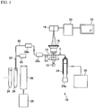
- FIG. 1 is a configuration diagram showing a biological sample imaging device according to an embodiment of the present invention.
- the biological sample imaging device 10 shown in FIG. 1 is an apparatus for taking images of particles in a liquid biological sample containing the particles.
- a urine sample is used as an example of the biological sample, and images of particles such as red blood cells, white blood cells, epithelial cells, and urinary casts in the urine sample are taken by the biological sample imaging device 10.
- the epithelial cells include squamous cells, transitional cells, and tubular epithelial cells.
- Examples of the urinary casts include hyaline casts, epithelial casts, red blood cell casts, white blood cell casts, fatty casts, granular casts, and waxy casts.
- the biological sample is not limited to urine, and may be blood, coelomic fluid, or the like.
- the biological sample may be a liquid directly collected from an organism, or may be a sample obtained by diluting the liquid with another liquid.
- the biological sample may be a sample obtained by dissolving particles collected from an organism into a liquid.
- particles contained in the urine sample particles such as red blood cells and white blood cells, each having a particle size of about 7 ⁇ m, are referred to as small particles in the present embodiment. Meanwhile, particles such as epithelial cells and urinary casts, each having a particle size of about 20 to 40 ⁇ m, are referred to as large particles in the present embodiment.
- the biological sample imaging device 10 includes a liquid flow channel 40, a light source 12, an objective lens 16, a camera 18, a data processing unit 20, a display unit 22, a syringe pump 24, a washing liquid container 26, a suction nozzle actuator 30, a washing chamber 36, and a waste liquid container 38.
- the liquid flow channel 40 includes a rod-shaped hollow suction nozzle 32, a liquid flow channel inside a second sensor 28b, a liquid flow channel inside a first sensor 28a, and an imaging cell 14 arranged in order from the upstream side.
- the liquid flow channel 40 further includes tubes 41, such as silicon tubes, connected to these components.
- the imaging cell 14 is formed from a translucent material into a plate shape.
- the imaging cell 14 has an inner space formed in a flat rectangular-parallelepiped shape, through which the urine sample flows. Thus, the imaging cell 14 allows observation of the urine sample held in the inner space from the outside.
- An upstream end of the liquid flow channel 40 is a tip of the suction nozzle 32, and a downstream end thereof is a suction/discharge port of the syringe pump 24.
- An inner space of the liquid flow channel 40 has a circular cross section, except a portion inside the imaging cell 14.
- a first position A is set on the upstream side of the imaging cell 14, and a second position B is set on the upstream side of the first position A. The first position A and the second position B will be described later in detail.
- the light source 12 includes a convex lens and a light emitting element such as an LED.
- the light source 12 is disposed directly below the imaging cell 14. Light emitted from the light emitting element is converted to parallel light by the convex lens, and the parallel light enters the imaging cell 14 made of a translucent material, from a lower portion of the imaging cell 14.
- the camera 18 is a CCD image sensor or a CMOS image sensor. The camera 18 is disposed directly above the imaging cell 14 together with the objective lens 16. The objective lens 16 and the camera 18 constitute a microscope camera. The microscope camera generates image data of the urine sample filled in the imaging cell 14.
- the display unit 22 is a display panel such as an LCD or an OLED. The display unit 22 displays information such as the image data generated by the camera 18.
- the data processing unit 20 is a computer system composed of a CPU and a memory as main components, and the camera 18 and the display unit 22 are connected to the data processing unit 20. Furthermore, although not illustrated in FIG. 1 , the following components are also connected to the data processing unit 20: the light source 12; a piston actuator 24a of the syringe pump 24; a solenoid valve provided in the tube between the syringe pump 24 and the washing liquid container 26; the first sensor 28a; the second sensor 28b; the suction nozzle actuator 30; and a solenoid valve provided in a drain tube of the washing chamber 36.
- An image analysis program and various control programs are installed on the data processing unit 20.
- the data processing unit 20 causes the display unit 22 to display the image data generated by the camera 18.
- the data processing unit 20 analyzes the image data generated by the camera 18, and detects particles reflected in the image data. Moreover, the data processing unit 20 controls the piston actuator 24a, the suction nozzle actuator 30, and the respective solenoid valves. Of the various functions to be implemented by the data processing unit 20, part or all of them may be implemented by another type of hardware such as ASIC or FPGA.
- the syringe pump 24 generates a negative pressure or a positive pressure with respect to the liquid flow channel 40 to cause a liquid or a gas to flow through the liquid flow channel 40 in a forward direction from the upstream end toward the downstream end or in a direction reverse to the forward direction.
- the syringe pump 24 sucks the urine sample from a sample container 34 such as a test tube, and fills the inner space of the imaging cell 14 with the urine sample. Further, the syringe pump 24 causes a liquid or a gas in the liquid flow channel 40 to flow reversely.
- the syringe pump 24 includes a cylinder and a piston that is inserted in the cylinder, and the piston actuator 24a is mounted to the piston.
- the piston actuator 24a which is an electric drive means such as a motor, pulls out the piston from the cylinder (forward actuation), or pushes the piston into the cylinder (reverse actuation).
- An opening is provided at a side surface of the cylinder.
- a tube which connects the inside of the washing liquid container 26 to the inside of the syringe pump 24, is connected to the opening.
- the suction nozzle actuator 30 causes the suction nozzle 32 to move in the up-down and left-right directions in accordance with a command from the data processing unit 20. Specifically, a plurality of sample containers 34 held in a rack are transported, by a transporting means such as a belt conveyor, to a suction position of the biological sample imaging device 10. The suction nozzle actuator 30 inserts the suction nozzle 32 in one of the sample containers 34 sequentially selected by the data processing unit 20, and pulls out the suction nozzle 32 from the sample container 34. When the suction nozzle 32 or the liquid flow channel 40 is washed, the suction nozzle actuator 30 inserts the suction nozzle 32 in the washing chamber 36.
- Each of the first sensor 28a and the second sensor 28b outputs data according to the type of an object (liquid or gas) that flows through a sensor position in the liquid flow channel 40.
- a conductivity sensor may be used as the first sensor 28a and the second sensor 28b.
- the conductivity sensor is provided so as to come into contact with the biological sample that passes through the liquid flow channel 40.
- the conductivity sensor includes two tubular electrodes separately disposed on the upstream side and the downstream side. The conductivity sensor outputs the conductivity of the object that flows between the electrodes.
- an optical sensor may be used as the first sensor 28a and the second sensor 28b.
- the optical sensor includes a light emitter and a light receiver arranged opposed to each other via a tube in which the biological sample flows.
- An object that flows in the tube is irradiated with light emitted from the light emitter, and a signal reflecting the intensity of the light that has transmitted through the object is outputted from the light receiver.
- FIG. 2A schematically shows the inside of a tube 41 during the forward actuation of the syringe pump 24.
- the liquid flow channel 40 such as the tube 41 is filled with a washing liquid 102 in the initial state.
- a biological sample 104 is filled in the imaging cell 14, firstly, a small amount of air 100 is sucked, and thereafter, a predetermined amount of the biological sample 104 is sucked from the sample container 34. Therefore, as shown in FIG. 2A , the air 100 (air gap) is positioned on the upstream side of the washing liquid 102, and the biological sample 104 is positioned on the upstream side of the air 100.
- the flow rate of the biological sample increases as the biological sample approaches the center axis of the liquid flow channel 40. Then, the particles in the biological sample gather around the center axis of the liquid flow channel 40, where the flow rate is highest.
- This axial concentration effect greatly acts on large particles such as epithelial cells 114 and urinary casts 116. As a result, the epithelial cells 114 and the urinary casts 116 are carried to the downstream side at a high flow rate.
- the density of the epithelial cells 114 and the urinary casts 116 is increased around a downstream end 104a of the biological sample 104 which flows through the liquid flow channel 40. Since red blood cells 112 and white blood cells 110 have sufficiently small particle sizes with respect to the flow-rate profile of the liquid flow channel 40, the axial concentration effect can be ignored.
- FIG. 3 is a distribution chart of large particles and small particles in the biological sample 104 immediately after the syringe pump 24 is forwardly actuated.
- the vertical axis indicates a value obtained by dividing the particle density (number of particles per unit volume) in the liquid flow channel 40 by the particle density in the sample container 34.
- the horizontal axis indicates the volume from the downstream end 104a of the biological sample 104. As shown in FIG. 3 , in the direction from the upstream end to the downstream end of the biological sample 104 (in the direction to the right in FIG. 3 ), the particle density of the large particles such as the epithelial cells 114 and the urinary casts 116 increases.
- the particle density ratio of the large particles reaches about 300% near the downstream end 104a of the biological sample 104. That is, by causing the biological sample 104 to flow through the liquid flow channel 40, the effect of condensing the large particles can be obtained. Therefore, by taking images of an area around the downstream end 104a of the biological sample 104 after the biological sample 104 is caused to flow through the liquid flow channel 40, images of the large particles such as the epithelial cells 114 and the urinary casts 116 can be efficiently taken.
- the particle density ratio of the small particles decreases in the direction from the upstream end to the downstream end of the biological sample 104.
- the particle density ratio of the small particles is less than 100% at any position. The reason of this is considered as follows. That is, as described above, the axial concentration effect hardly acts on the small particles.
- the biological sample 104 is diluted toward the downstream side by the washing liquid 102 attached to an inner wall surface of the liquid flow channel 40.
- the density of the large particles such as the epithelial cells 114 and the urinary casts 116 can be increased near the downstream end 104a of the biological sample 104.
- Increasing the density of the particles allows the particles to be efficiently reflected in images.
- the imaging cell 14 has an inner space that expands in the horizontal direction, and the entirety or a part of the inner space is set as an imaging range for the camera 18. If the downstream end 104a of the biological sample 104 is located within the imaging range, the large particles are concentrated in a part of the imaging range, and are overlapped with each other in the vertical direction, which makes it difficult to reflect the individual particles in images.
- a pump control is executed, by which the large particles concentrated around the downstream end 104a of the biological sample 104 is dispersed again. That is, in the present embodiment, forward actuation of the syringe pump 24 is temporarily stopped immediately before the biological sample 104 enters the inner space of the imaging cell 14. Specifically, when the downstream end 104a of the biological sample 104 has reached the first position A (refer to FIG. 1 ) that is set on the upstream side of the imaging cell 14, the operation of the syringe pump 24 is stopped. Then, the syringe pump 24 is reversely actuated until the downstream end 104a of the biological sample 104 reaches the second position B. The second position B is set on the upstream side relative to the first position A. That is, the biological sample 104 is pushed back to the upstream side.
- FIG. 2B schematically shows the inside of the liquid flow channel 40 during the reverse actuation of the syringe pump 24.
- the biological sample 104 moves to the upstream side, that is, toward the suction nozzle 32.
- the axial concentration effect greatly acts on the large particles such as the epithelial cells 114 and the urinary casts 116. Therefore, the large particles concentrated around the downstream end 104a move in the upstream direction relative to the small particles, as shown in FIG. 2B .
- the large particles concentrated around the downstream end 104a can be favorably dispersed to a portion apart from the downstream end 104a.
- the syringe pump 24 When the downstream end 104a of the biological sample 104 has reached the second position B, the syringe pump 24 is temporarily stopped, and then the syringe pump 24 is forwardly actuated until the downstream end 104a of the biological sample 104 reaches a third position C.
- the third position C is set on the downstream side of the imaging cell 14 in the liquid flow channel 40.
- the inner space of the imaging cell 14 can be filled with the biological sample 104.
- FIG. 4A is a perspective view of the imaging cell 14.
- the imaging cell 14 includes: an inner space 14e for holding a urine sample; and an inflow path 14f and an outflow path 14g, through which the inner space 14e communicates with the outside.
- the imaging cell 14 has a rectangular parallelepiped outer shape that is flat and extends in one direction.
- the inner space 14e also has a rectangular parallelepiped shape that is flat and extends in one direction.
- the inner space 14e is arranged along the outer shape of the imaging cell 14. The imaging cell 14 is placed so that the bottom surface of the inner space 14e becomes horizontal.
- the inner space 14e is sandwiched, in the vertical direction, by a thin plate part 14a and a thin plate part 14b which are parallel and opposed to each other. At least the thin plate part 14a and the thin plate part 14b of the imaging cell 14 are formed from a translucent material such as glass or resin.
- the inner space 14e has a rectangular parallelepiped shape that extends in one direction as described above, and the surface at one end thereof in the longitudinal direction is an upstream end 14c while the surface at the other end thereof in the longitudinal direction is a downstream end 14d.
- the inflow path 14f communicating with an opening at a side surface of the imaging cell 14 is formed in a portion, of a side wall of the imaging cell 14, right next to the upstream end 14c of the inner space 14e.
- the outflow path 14g communicating with an opening at the side surface of the imaging cell 14 is formed in a portion, of the side wall of the imaging cell 14, right next to the downstream end 14d of the inner space 14e.
- a tube 41 communicating with the first sensor 28a is connected to the inflow path 14f, and a tube 41 communicating with the syringe pump 24 is connected to the outflow path 14g.
- the light source 12 is disposed below the imaging cell 14, and parallel light enters the imaging cell 14 from the thin plate part 14b side.
- the microscope camera composed of the objective lens 16 and the camera 18 is disposed above the imaging cell 14.
- the microscope camera takes an image of the urine sample filled in the inner space 14e, through the thin plate part 14a.
- the imaging range range utilized for display and/or image analysis
- the imaging range may be a part of the inner space 14e.
- FIG. 4B schematically shows a cross section of the imaging cell 14 immediately after the imaging cell 14 has been filled with the biological sample 104.
- FIG. 4C schematically shows a cross section of the imaging cell 14 after a predetermined time period has passed from the filling with the biological sample 104.
- the particles are floating in the space between the thin plate part 14a and the thin plate part 14b.
- the particles are precipitated at the bottom as shown in FIG. 4C .
- the microscope camera composed of the objective lens 16 and the camera 18 is focused on the vicinity of the surfaces of the particles precipitated at the bottom, and takes a macrophotograph.
- a sufficient number of large particles are present between the thin plate part 14a and the thin plate part 14b, and moreover, the large particles are favorably dispersed. Therefore, even when the large particles are precipitated at the bottom, the large particles hardly overlap each other in the vertical direction. As a result, images of the individual large particles can be clearly taken.
- the height of the inner space 14e i.e., the interval between the thin plate part 14a and the thin plate part 14b, is smaller than the dimension of any part of the liquid flow channel 40, except the imaging cell 14.
- the height of the inner space 14e is smaller than the inner diameters of the suction nozzle 32 and the tube 41 provided on the upstream side relative to the imaging cell 14.
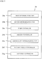
- FIG. 5 is a functional block diagram showing the data processing unit 20.
- the data processing unit 20 is configured by a computer system, and implements various functions by executing programs.
- the data processing unit 20 functionally includes a first determination unit 20a, a second determination unit 20b, a pump controller 20c, an imaging controller 20d, an abnormality determination unit 20e, a suction nozzle controller 20f, and an agitation controller 20g.
- the first determination unit 20a determines that the downstream end 104a of the biological sample 104 has reached the first position A provided on the liquid flow channel 40. For example, the first determination unit 20a may determine that the downstream end 104a of the biological sample 104 has reached the first position A, on the basis of the suction amount or the discharge amount of the syringe pump 24. The suction amount or the discharge amount of the syringe pump 24 can be determined based on the operation amount of the piston actuator 24a. In addition, the cross-sectional area of the liquid flow channel 40 is already known, and the internal capacity of the liquid flow channel 40 from the upstream end to the first position A is also already known. Accordingly, when the suction amount of the syringe pump 24 has reached the known internal capacity, the first determination unit 20a can determine that the downstream end 104a of the biological sample 104 has reached the first position A provided on the liquid flow channel 40.
- the first determination unit 20a may determine that the downstream end 104a of the biological sample 104 has reached the first position A, on the basis of an output from a sensor provided in the liquid flow channel 40.
- a conductivity sensor may be disposed at the first position A, and the first determination unit 20a may determine that the downstream end 104a of the biological sample 104 has reached the first position A, on the basis of the conductivity outputted from the conductivity sensor.
- the air 100 is caused to be adjacent to the downstream side of the biological sample 104, when the conductivity of the biological sample 104 is detected while the conductivity of the air 100 is being detected, this timing allows the determination that the downstream end 104a of the biological sample 104 has reached the position of the conductivity sensor, i.e., the first position A.
- the first determination unit 20a may determine that the downstream end 104a of the biological sample 104 has reached the first position A, on the basis of both an output from the sensor and the suction amount/discharge amount of the syringe pump 24.
- the first sensor 28a is mounted on the upstream side relative to the first position A, and the internal capacity of the liquid flow channel 40 from the detection position of the first sensor 28a to the first position A is already known.
- the first determination unit 20a can determine that the downstream end 104a of the biological sample 104 has reached the first position A.
- the second determination unit 20b determines that the downstream end 104a of the biological sample 104 has reached the second position B provided on the liquid flow channel 40. This determination can be performed similarly to the determination by the first determination unit 20a. For example, the internal capacity of the liquid flow channel 40 from the first position A to the second position B is already known. Therefore, the syringe pump 24 is reversely actuated from the state where the downstream end 104a of the biological sample 104 is located at the first position A, then if the discharge amount thereof reaches the known internal capacity, it can be determined that the downstream end 104a has reached the second position B.
- the second determination unit 20b may determine that the downstream end 104a of the biological sample 104 has reached the second position B, on the basis of an output from a sensor provided in the liquid flow channel 40.
- a conductivity sensor may be disposed at the second position B, and the second determination unit 20b may determine that the downstream end 104a of the biological sample 104 has reached the second position B, on the basis of the conductivity outputted from the conductivity sensor.
- the air 100 is caused to be adjacent to the downstream side of the biological sample 104, when the conductivity of the air 100 is detected while the conductivity of the biological sample 104 is being detected, this timing allows the determination that the downstream end 104a of the biological sample 104 has reached the position of the conductivity sensor, i.e., the second position B.
- the pump controller 20c instructs the operation of the piston actuator 24a.
- the pump controller 20c causes the syringe pump 24 to sequentially perform: a first operation (forward actuation) in which the biological sample 104, having been introduced into the liquid flow channel 40, is caused to flow in the forward direction, and the downstream end 104a thereof is caused to reach the first position A; and a second operation (reverse operation) in which the biological sample 104 is caused to flow in the reverse direction, and the downstream end 104a thereof is caused to reach the second position B.
- the first operation includes: a liquid introducing operation of introducing a predetermined amount of the biological sample 104 from the tip of the suction nozzle 32 into the liquid flow channel 40; and an air introducing operation of, after the liquid introducing operation, pulling up the suction nozzle 32 from the sample container 34, and introducing air from the tip of the suction nozzle 32 into the liquid flow channel 40.
- the pump controller 20c causes the piston actuator 24a to perform a third operation of causing the biological sample 104 to flow in the forward direction again.
- the downstream end 104a of the biological sample 104 is caused to reach the third position C.
- the third position C may be set at the downstream end 14d of the inner space 14e of the imaging cell 14, or at any position that is near the imaging cell 14 and on the downstream side relative to the downstream end 14d.
- the third operation is performed with the tip of the suction nozzle 32 being pulled up from the liquid surface in the sample container 34.
- the downstream end 104a of the biological sample 104 can be prevented from entering the imaging range. There is a possibility that the washing liquid 102 or the like attached to the inner wall of the liquid flow channel 40 is mixed into a portion around the downstream end 104a of the biological sample 104. If the third position C is set on the downstream side relative to the inner space 14e of the imaging cell 14, image-taking of the biological sample 104 can be performed while avoiding such a portion.
- the large particles concentrated around the downstream end 104a of the biological sample 104 due to the first operation are pushed back to the downstream side, whereby a sufficient number of large particles can be ensured within the imaging range. Further, the second operation allows the large particles to be favorably dispersed within the imaging range.
- the first position A is set on the upstream side relative to the inner space 14e of the imaging cell 14, which is the imaging range.
- the large particles can be dispersed in the liquid flow channel 40 at the upstream side of the imaging cell 14, and thereafter, the biological sample 104 can be filled in the imaging cell 14. Therefore, the large particles such as the epithelial cells 114 and the urinary casts 116 can be prevented from clogging the imaging cell 14. That is, since the height of the inner space 14e of the imaging cell 14 is very low as mentioned above, clogging of the large particles is a concern. However, according to the present embodiment, such clogging can be prevented.
- the internal capacity from the second position B to the tip of the suction nozzle 32 is desired to be greater than the internal capacity of the liquid flow channel 40 at least within the imaging range (the internal capacity of the inner space 14e of the imaging cell 14). Otherwise, the already sucked biological sample 104 is discharged from the tip of the suction nozzle 32 due to the second operation.
- the internal capacity of the liquid flow channel 40 from the second position B to the upstream end 14c of the imaging cell 14 is desired to be not greater than 10 times the internal capacity of the liquid flow channel 40 within the imaging range, that is, the internal capacity of the inner space 14e of the imaging cell 14.
- the movement amount of the biological sample 104 during the third operation can be reduced, thereby preventing the large particles from being again concentrated around the downstream end 104a of the biological sample 104 due to the third operation.
- the second operation is performed with the tip of the suction nozzle 32 being pulled up from the liquid surface in the sample container 34. Thus, air is prevented from being supplied into the sample container 34.
- the internal capacity of the liquid flow channel 40 from the first position A to the second position B is desired to be not greater than one-tenth of the internal capacity from the tip of the suction nozzle 32 to the first position A.
- the imaging controller 20d waits for elapse of a predetermined time period required for precipitation of the particles, and then causes the camera 18 to take images of the particles in the biological sample 104 within the imaging range, that is, within the inner space 14e of the imaging cell 14.
- the images taken of the biological sample 104 are displayed on the display unit 22, or used for image analysis.
- the imaging controller 20d takes images of the biological sample 104 for each of the plurality of sample containers 34 held in the rack. At this time, the pump controller 20c performs the aforementioned first to third operations for each biological sample 104.
- the abnormality determination unit 20e detects an abnormality that the amount of the biological sample 104 sucked from the sample container 34 is less than a specified amount, when the biological sample 104 is supplied into the imaging cell 14. Specifically, a shortage monitoring period is provided after start of the air introduction in the first operation, and if air is detected by the second sensor 28b during the shortage monitoring period, it is determined that the biological sample 104 is insufficient.
- the shortage monitoring period is a period during which a specified amount of the biological sample 104 should pass through the detection position of the second sensor 28b. When such an abnormality is detected, the abnormality is displayed on the display unit 22, for example.
- the abnormality determination unit 20e can improve the reliability of the images of the biological sample 104.
- the suction nozzle controller 20f instructs the operation of the suction nozzle actuator 30.
- the agitation controller 20g causes the biological sample 104 in the sample container 34 to be agitated.
- an agitation nozzle (not shown) is inserted in the sample container 34, and a certain amount of the biological sample 104 is sucked by using an agitation pump (not shown), and thereafter, the sucked biological sample 104 is returned to the sample container 34 by the agitation pump, thereby agitating the biological sample 104 in the sample container 34.
- the biological sample 104 in the sample container 34 may be agitated by discharging air from the agitation nozzle.
- the biological sample 104 may be agitated by using the syringe pump 24 and the suction nozzle 32 in the same manner as described above.
- an exemplary structure is adopted in which an agitation nozzle (not shown) is formed integrally with the suction nozzle 32, and the biological sample 104 in the sample container 34 is agitated by using an agitation pump (not shown) different from the syringe pump 24.
- the integrated agitation nozzle and suction nozzle 32 can be actuated together by the suction nozzle actuator 30.
- FIG. 6 shows, in a time series manner, how the biological sample 104 flows through the liquid flow channel 40.
- FIG. 7A and FIG. 7B are flowcharts showing the operation of the biological sample imaging device 10.
- the pump controller 20c causes the syringe pump 24 to suck a certain volume of air 100 while the suction nozzle 32 is not inserted in the sample container 34, thereby introducing the certain volume of air 100 to an end of the liquid flow channel 40 to form an air gap (S101 in FIG. 7A , and (b) of FIG. 6 ). For example, about 25 ⁇ L of air 100 may be sucked into the liquid flow channel 40.
- the suction nozzle actuator 30 causes the suction nozzle 32 to be inserted in one sample container 34 together with an agitation nozzle (not shown) (S102 in FIG. 7A ). Then, the agitation controller 20g causes the biological sample 104 contained in the sample container 34 to be agitated (S103 in FIG. 7A ).
- the pump controller 20c forwardly drives the piston actuator 24a to suck a specified amount of the biological sample 104 from the sample container 34 (S104 in FIG. 7A ). For example, about 300 ⁇ L of the biological sample 104 may be sucked into the liquid flow channel 40.
- the abnormality determination unit 20e monitors a rapid decrease in the conductivity outputted from the second sensor 28b, that is, it monitors passing of the air gap. If the conductivity does not rapidly decrease, the abnormality determination unit 20e determines that the operation of the syringe pump 24 is abnormal, and ends the process.
- the abnormality determination unit 20e determines whether or not the conductivity outputted from the second sensor 28b is equal to or higher than a predetermined threshold (S105 in FIG. 7A ). If the conductivity is less than the predetermined threshold, the abnormality determination unit 20e determines that abnormality has occurred in the biological sample 104, and ends the process.
- the suction nozzle controller 20f causes the suction nozzle actuator 30 to pull up the suction nozzle 32 from the sample container 34 (S106 in FIG. 7A ).
- the pump controller 20c causes air to be sucked from the suction nozzle 32 (S107 in FIG. 7A ).
- a shortage monitoring period is set, and the abnormality determination unit 20e monitors a rapid decrease in the conductivity outputted from the second sensor 28b. If the conductivity rapidly decreases, the abnormality determination unit 20e determines that the biological sample 104 is less than the specified amount, and ends the process.
- the pump controller 20c causes the suction of air to be performed until the air 100 is detected by the first sensor 28a (S108 in FIG. 7A ).
- the suction of air causes the biological sample 104 having been introduced into the liquid flow channel 40 to move to the downstream side. If the conductivity that is outputted from the first sensor 28a rapidly decreases, it can be determined that the air 100 has taken the place of the object, i.e., the washing liquid 102, located at the detection position of the first sensor 28a. At this timing, the downstream end of the air 100 (air gap) reaches the detection position of the first sensor 28a ((d) of FIG. 6 ).
- the pump controller 20c further causes a predetermined amount of air to be sucked (S109 in FIG. 7A , (e) of FIG. 6 ).
- the first determination unit 20a determines whether or not the suction amount of the syringe pump 24 has reached the predetermined amount, and the pump controller 20c stops the operation of the syringe pump 24 when the suction amount of the syringe pump 24 has reached the predetermined amount.
- the suction amount of the syringe pump 24 in S109 is a value obtained by adding the volume of the air 100 (air gap) to the internal capacity from the detection position of the first sensor 28a to the first position A.
- the downstream end 104a of the biological sample 104 reaches the first position A.
- the first position A may be provided about 60 ⁇ L upstream of the upstream end 14c of the inner space 14e of the imaging cell 14.
- the operation from S104 to S109 corresponds to the first operation of the syringe pump 24.
- the pump controller 20c instructs the piston actuator 24a to perform reverse actuation, thereby causing a predetermined amount of air to be discharged from the upstream end of the liquid flow channel 40 (S110 in FIG. 7B ).
- the second determination unit 20b determines whether or not the discharge amount of the syringe pump 24 has reached the predetermined amount, and the pump controller 20c stops the operation of the syringe pump 24 if the discharge amount of the syringe pump 24 has reached the predetermined amount.
- the discharge amount of the syringe pump 24 is equal to the internal capacity from the first position A to the second position B.
- the discharge amount may be about 30 ⁇ L.
- the downstream end 104a of the biological sample 104 reaches the second position B ((f) of FIG. 6 ).
- the operation in S110 corresponds to the second operation of the syringe pump 24.
- the pump controller 20c instructs the piston actuator 24a to perform forward actuation, and causes a predetermined amount of air to be sucked (S111 in FIG. 7B ). Specifically, it is determined whether or not the suction amount of the syringe pump 24 has reached the predetermined amount, and the pump controller 20c stops the operation of the syringe pump 24 if the suction amount of the syringe pump 24 has reached the predetermined amount.
- the suction amount of the syringe pump 24 is equal to the internal capacity of the liquid flow channel 40 from the second position B to the third position C. For example, this suction amount may be about 120 ⁇ L.
- this suction amount may be about 120 ⁇ L.
- the capacity between the downstream end 14d of the imaging cell 14 and the third position C, which is the imaging range, may be 20 ⁇ L.
- the capacity of the inner space 14e of the imaging cell 14 is 15 ⁇ L, a portion corresponding to 20 ⁇ L to 35 ⁇ L from the downstream end 104a of the biological sample 104 is filled in the inner space 14e of the imaging cell 14.
- the operation in S111 corresponds to the third operation of the syringe pump 24.
- the biological sample 104 is filled in the inner space 14e of the imaging cell 14, and the imaging controller 20d causes image data of the biological sample 104 to be generated (S112 in FIG. 7B ).
- washing of the liquid flow channel 40 and the syringe pump 24 is performed (S113 in FIG. 7B ).
- the suction nozzle controller 20f instructs the suction nozzle actuator 30 to insert the suction nozzle 32 in the washing chamber 36.
- the piston of the syringe pump 24 is sufficiently pulled out, and the washing liquid stored in the washing liquid container 26 flows into the syringe pump 24 when the solenoid valve between the syringe pump 24 and the washing liquid container 26 is opened.
- the washing liquid immediately reaches the tip of the suction nozzle 32, whereby the inside of the liquid flow channel 40 and the inside of the syringe pump 24 are washed throughout.
- the air, the urine sample, and the washing liquid are discharged from the suction nozzle 32 to be stored in the waste liquid container 38. Thereafter, the solenoid valve provided in a drain of the washing chamber 36 is temporarily closed, whereby the washing liquid is stored in the washing chamber 36. Thereafter, the solenoid valve is opened. Thus, the outside of the suction nozzle 32 is also washed.
- the washing liquid may be supplied from the suction nozzle 32 or from an exclusive channel, to the washing chamber 36.
- FIG. 8A is a distribution chart of the large particles after the biological sample 104 has been caused to flow through the liquid flow channel 40 by the biological sample imaging device 10.
- FIG. 8B is a distribution chart of the small particles after the biological sample 104 has been caused to flow through the liquid flow channel 40 by the biological sample imaging device 10.
- a broken line indicates the number of large particles per unit volume (about 70/ ⁇ L) that is measured by a flow cytometer. The broken line indicates the number of large particles per unit volume in the sample container 34. As shown in FIG.
- the number of large particles per unit volume is 1.5 times or more at any position within the range of 165 ⁇ L from the downstream end 104a of the biological sample 104. Accordingly, it is found that, also within the imaging range, the number of large particles per unit volume is 1.5 times or more as compared with the original number of large particles per unit volume.
- a broken line indicates the number of small particles per unit volume (about 790/ ⁇ L) that is measured by a flow cytometer. It is found that 80% or more is ensured as compared with the original number of small particles per unit volume.
- the pump controller 20c causes the syringe pump 24 to perform the first operation, whereby large cells such as the epithelial cells 114 and the urinary casts 116 can be concentrated around the downstream end 104a of the biological sample 104. Thereafter, the pump controller 20c causes the syringe pump 24 to perform the second operation, whereby the large particles concentrated around the downstream end 104a of the biological sample 104 can be dispersed to the upstream side.
- the inner space 14e of the imaging cell 14 is filled with the biological sample 104 that has been caused to forwardly and reversely flow through the liquid flow channel 40. Therefore, a sufficient number of large particles are present in the imaging cell 14, and moreover, these large particles are moderately dispersed, whereby the individual large particles can be reflected in images taken by the camera 18. As a result, the accuracy of the urine test can be improved.
- the epithelial cells 114 appear in urine due to damage of a kidney or the urinary tract, and images thereof are important information for judging which portion of the kidney or urinary tract is damaged and the extent of the damage.
- the images of the epithelial cells 114 are used for diagnosis of diseases such as cystitis and urethritis.
- the urinary casts 116 appear in urine when a renal tubular lumen is temporarily closed and thereafter urine flows again, and images thereof are also important information for judging which portion of the kidney or urinary tract is abnormal and the extent of the abnormality.
- the images of the urinary casts 116 are used for diagnosis of diseases such as chronic nephritis, glomerulonephritis, pyelonephritis, and nephrotic syndrome.
- diseases such as chronic nephritis, glomerulonephritis, pyelonephritis, and nephrotic syndrome.
- large particles such as the epithelial cells 114 and the urinary casts 116 are contained in a urine sample.
- even a small number of large particles provide clinically very important findings as described above.
- the biological sample imaging device 10 the large particles in the urine sample, which provide such important findings, can be efficiently reflected in images so as not to overlap each other, through the aforementioned concentration and dispersion processes.
- the reliability of the urine test can be significantly improved.
- the present invention is not limited to the above embodiment. Various modifications of the above embodiment can be made, and these modifications are also within the scope of the present invention.
- the first sensor 28a and the second sensor 28b are used in the above description, these sensors are not necessarily required for controlling the position of the downstream end 104a of the biological sample 104.
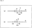
- the third operation by the pump controller 20c is not necessarily required. That is, as shown in FIG. 9 , the first position A may be provided on the downstream side relative to the imaging range of the imaging cell 14, and the second position B may be provided at the downstream end of the imaging range of the imaging cell 14 or on the downstream side relative to the downstream end. In this case, the inner space 14e of the imaging cell 14 is filled with the biological sample 104 immediately after the second operation has been performed. Thus, the time interval from start of suction of the biological sample 104 to image-taking by the camera 18 can be reduced.
- the biological sample imaging device and the biological sample imaging method according to the present invention can be favorably used for, for example, image-taking of a liquid biological sample containing particles, such as urine and blood.
Landscapes
- Health & Medical Sciences (AREA)
- Chemical & Material Sciences (AREA)
- Life Sciences & Earth Sciences (AREA)
- Physics & Mathematics (AREA)
- Pathology (AREA)
- Biochemistry (AREA)
- General Health & Medical Sciences (AREA)
- General Physics & Mathematics (AREA)
- Immunology (AREA)
- Analytical Chemistry (AREA)
- Engineering & Computer Science (AREA)
- Dispersion Chemistry (AREA)
- Biomedical Technology (AREA)
- Urology & Nephrology (AREA)
- Biophysics (AREA)
- Hematology (AREA)
- Molecular Biology (AREA)
- Food Science & Technology (AREA)
- Medicinal Chemistry (AREA)
- Investigating Or Analysing Biological Materials (AREA)
- Sampling And Sample Adjustment (AREA)
- Automatic Analysis And Handling Materials Therefor (AREA)
Abstract
Description
- The present invention relates to a biological sample imaging device and a biological sample imaging method, and particularly to imaging of liquid biological samples containing particles, such as urine and blood.
- A urine sample contains particles such as red blood cells, white blood cells, epithelial cells, and urinary casts, and observing these particles in the urine sample is effective in diagnosing diseases of the kidney and the urinary tract. The prior art documents below each disclose a device for imaging particles contained in a biological sample such as a urine sample.
-
- [PTL 1] International Publication
WO 2008/007725 - [PTL 2] International Publication
WO 2013/056415 - In a test for a liquid biological sample such as a urine sample, adopting a structure, in which the biological sample is supplied from a container to an imaging cell (imaging range) through a liquid flow channel such as a tube or a pipe, is advantageous for automation of the test. In the process of investigating this structure, the inventors of the present invention have obtained the findings below.
- That is, when the biological sample is caused to flow through the liquid flow channel as described above, an axial concentration effect acts on the particles in the biological sample. That is, according to fluid dynamics, the flow rate of the biological sample increases as the biological sample approaches the center axis of the liquid flow channel, and the particles in the biological sample gather around the center axis of the liquid flow channel, where the flow rate is highest. This axial concentration effect greatly acts on large-sized particles. As a result, the large-sized particles are flowed at a high flow rate to the downstream side, and the density of the large-sized particles increases near a downstream end of the biological sample (at the head of the biological sample) flowing through the liquid flow channel.
- In a urine sample, generally, large-sized particles such as epithelial cells and urinary casts are low in density, but the density of these particles can be increased in a downstream end portion of the biological sample by using the aforementioned axial concentration effect. By increasing the density of the particles, the particles can be efficiently reflected in images. Meanwhile, in image-taking with a camera, an imaging range has a two-dimensional expansion to some extent. However, if a particle imaging range is set in the downstream end portion of the biological sample, large-sized particles are concentrated and overlap each other in a downstream end portion of the imaging range, which makes it difficult to reflect the individual particles in images. Furthermore, if the imaging range is set on the upstream side of the downstream end portion of the biological sample so as to be apart from the downstream end portion, there is a possibility that a sufficient number of large-sized particles are not present within the imaging range. In this case, a sufficient number of large-sized particles cannot be reflected in images.
- Therefore, an object of the present invention is to provide a biological sample imaging device and a biological sample imaging method that are capable of disposing a sufficient number of large-sized particles in a biological sample so as to be moderately dispersed within an imaging range.
- A biological sample imaging device according to one aspect of the present invention includes: a liquid flow channel through which a liquid biological sample containing particles flows, the liquid flow channel having, at a predetermined position, an imaging range within which images of the particles contained in the biological sample are taken; a pump configured to cause the biological sample, which has been introduced from a container into the liquid flow channel, to flow in a forward direction from an upstream side toward a downstream side or in a direction reverse to the forward direction; a pump controller configured to cause the pump to sequentially perform a first operation of causing the biological sample introduced into the liquid flow channel to flow in the forward direction, and a second operation of causing the biological sample to flow in the reverse direction; and an imaging unit configured to take, within the imaging range, images of the particles contained in the biological sample that remains in the liquid flow channel after the second operation.
- A biological sample imaging method includes: a first step of introducing a biological sample containing particles into a liquid flow channel; a second step of causing the biological sample introduced into the liquid flow channel to flow in a forward direction from an upstream side toward a downstream side; a third step of causing the biological sample to flow in a reverse direction after the second step; and an imaging step of taking, within an imaging range set on the liquid flow channel, images of the particles contained in the biological sample that remains in the liquid flow channel after the third step.
- According to the present invention, it is possible to realize a biological sample imaging device and a biological sample imaging method that are capable of disposing a sufficient number of large-sized particles in a biological sample so as to be moderately dispersed within an imaging range.
-
- [
FIG. 1] FIG. 1 is a configuration diagram of a biological sample imaging device according to one embodiment of the present invention. - [
FIG. 2A] FIG. 2A is a diagram schematically showing the inside of a liquid flow channel when a pump is forwardly actuated. - [
FIG. 2B] FIG. 2B is a diagram schematically showing the inside of the liquid flow channel when the pump is reversely actuated. - [
FIG. 3] FIG. 3 is a distribution chart of large particles and small particles in a biological sample immediately after the pump is forwardly actuated. - [
FIG. 4A] FIG. 4A is a perspective view showing an imaging cell. - [
FIG. 4B] FIG. 4B is a diagram schematically showing a cross section of the imaging cell immediately after the imaging cell is filled with the biological sample. - [
FIG. 4C] FIG. 4C is a diagram schematically showing a cross section of the imaging cell after a predetermined time period has passed from the filling of the imaging cell with the biological sample. - [
FIG. 5] FIG. 5 is a functional block diagram of a data processing unit. - [
FIG. 6] FIG. 6 is a diagram showing, in a time series manner, how an object such as a biological sample flows through the liquid flow channel. - [
FIG. 7A] FIG. 7A is a flowchart showing the operation of the biological sample imaging device according to the embodiment of the present invention. - [
FIG. 7B] FIG. 7B is a flowchart showing the operation of the biological sample imaging device according to the embodiment of the present invention. - [
FIG. 8A] FIG. 8A is a distribution chart of large particles after the biological sample is caused to flow through the liquid flow channel by the biological sample imaging device according to the embodiment of the present invention. - [
FIG. 8B] FIG. 8B is a distribution chart of small particles after the biological sample is caused to flow through the liquid flow channel by the biological sample imaging device according to the embodiment of the present invention. - [
FIG. 9] FIG. 9 is a diagram showing another example of pump control by the biological sample imaging device according to the embodiment of the present invention. - Hereinafter, an embodiment of the present invention will be described in detail with reference to the drawings.
-
FIG. 1 is a configuration diagram showing a biological sample imaging device according to an embodiment of the present invention. The biologicalsample imaging device 10 shown inFIG. 1 is an apparatus for taking images of particles in a liquid biological sample containing the particles. In this embodiment, a urine sample is used as an example of the biological sample, and images of particles such as red blood cells, white blood cells, epithelial cells, and urinary casts in the urine sample are taken by the biologicalsample imaging device 10. Examples of the epithelial cells include squamous cells, transitional cells, and tubular epithelial cells. Examples of the urinary casts include hyaline casts, epithelial casts, red blood cell casts, white blood cell casts, fatty casts, granular casts, and waxy casts. - The biological sample is not limited to urine, and may be blood, coelomic fluid, or the like. The biological sample may be a liquid directly collected from an organism, or may be a sample obtained by diluting the liquid with another liquid. Alternatively, the biological sample may be a sample obtained by dissolving particles collected from an organism into a liquid.
- Of the particles contained in the urine sample, particles such as red blood cells and white blood cells, each having a particle size of about 7 µm, are referred to as small particles in the present embodiment. Meanwhile, particles such as epithelial cells and urinary casts, each having a particle size of about 20 to 40 µm, are referred to as large particles in the present embodiment.
- As shown in
FIG. 1 , the biologicalsample imaging device 10 according to the present embodiment includes aliquid flow channel 40, alight source 12, anobjective lens 16, acamera 18, adata processing unit 20, adisplay unit 22, asyringe pump 24, a washingliquid container 26, asuction nozzle actuator 30, awashing chamber 36, and awaste liquid container 38. Theliquid flow channel 40 includes a rod-shapedhollow suction nozzle 32, a liquid flow channel inside asecond sensor 28b, a liquid flow channel inside afirst sensor 28a, and animaging cell 14 arranged in order from the upstream side. Theliquid flow channel 40 further includestubes 41, such as silicon tubes, connected to these components. Theimaging cell 14 is formed from a translucent material into a plate shape. Theimaging cell 14 has an inner space formed in a flat rectangular-parallelepiped shape, through which the urine sample flows. Thus, theimaging cell 14 allows observation of the urine sample held in the inner space from the outside. An upstream end of theliquid flow channel 40 is a tip of thesuction nozzle 32, and a downstream end thereof is a suction/discharge port of thesyringe pump 24. An inner space of theliquid flow channel 40 has a circular cross section, except a portion inside theimaging cell 14. On theliquid flow channel 40, a first position A is set on the upstream side of theimaging cell 14, and a second position B is set on the upstream side of the first position A. The first position A and the second position B will be described later in detail. - The
light source 12 includes a convex lens and a light emitting element such as an LED. Thelight source 12 is disposed directly below theimaging cell 14. Light emitted from the light emitting element is converted to parallel light by the convex lens, and the parallel light enters theimaging cell 14 made of a translucent material, from a lower portion of theimaging cell 14. Thecamera 18 is a CCD image sensor or a CMOS image sensor. Thecamera 18 is disposed directly above theimaging cell 14 together with theobjective lens 16. Theobjective lens 16 and thecamera 18 constitute a microscope camera. The microscope camera generates image data of the urine sample filled in theimaging cell 14. Thedisplay unit 22 is a display panel such as an LCD or an OLED. Thedisplay unit 22 displays information such as the image data generated by thecamera 18. - The
data processing unit 20 is a computer system composed of a CPU and a memory as main components, and thecamera 18 and thedisplay unit 22 are connected to thedata processing unit 20. Furthermore, although not illustrated inFIG. 1 , the following components are also connected to the data processing unit 20: thelight source 12; apiston actuator 24a of thesyringe pump 24; a solenoid valve provided in the tube between thesyringe pump 24 and thewashing liquid container 26; thefirst sensor 28a; thesecond sensor 28b; thesuction nozzle actuator 30; and a solenoid valve provided in a drain tube of thewashing chamber 36. An image analysis program and various control programs are installed on thedata processing unit 20. Thedata processing unit 20 causes thedisplay unit 22 to display the image data generated by thecamera 18. In addition, thedata processing unit 20 analyzes the image data generated by thecamera 18, and detects particles reflected in the image data. Moreover, thedata processing unit 20 controls thepiston actuator 24a, thesuction nozzle actuator 30, and the respective solenoid valves. Of the various functions to be implemented by thedata processing unit 20, part or all of them may be implemented by another type of hardware such as ASIC or FPGA. - The
syringe pump 24 generates a negative pressure or a positive pressure with respect to theliquid flow channel 40 to cause a liquid or a gas to flow through theliquid flow channel 40 in a forward direction from the upstream end toward the downstream end or in a direction reverse to the forward direction. Specifically, thesyringe pump 24 sucks the urine sample from asample container 34 such as a test tube, and fills the inner space of theimaging cell 14 with the urine sample. Further, thesyringe pump 24 causes a liquid or a gas in theliquid flow channel 40 to flow reversely. Thesyringe pump 24 includes a cylinder and a piston that is inserted in the cylinder, and thepiston actuator 24a is mounted to the piston. In accordance with a command from thedata processing unit 20, thepiston actuator 24a, which is an electric drive means such as a motor, pulls out the piston from the cylinder (forward actuation), or pushes the piston into the cylinder (reverse actuation). An opening is provided at a side surface of the cylinder. A tube, which connects the inside of the washingliquid container 26 to the inside of thesyringe pump 24, is connected to the opening. When the piston is pulled out from the cylinder and thereby the inner space between the piston and the cylinder comes to have a predetermined capacity or more, the inside of the washingliquid container 26 becomes communicable with the inside of thesyringe pump 24. - The
suction nozzle actuator 30 causes thesuction nozzle 32 to move in the up-down and left-right directions in accordance with a command from thedata processing unit 20. Specifically, a plurality ofsample containers 34 held in a rack are transported, by a transporting means such as a belt conveyor, to a suction position of the biologicalsample imaging device 10. Thesuction nozzle actuator 30 inserts thesuction nozzle 32 in one of thesample containers 34 sequentially selected by thedata processing unit 20, and pulls out thesuction nozzle 32 from thesample container 34. When thesuction nozzle 32 or theliquid flow channel 40 is washed, thesuction nozzle actuator 30 inserts thesuction nozzle 32 in thewashing chamber 36. - Each of the
first sensor 28a and thesecond sensor 28b outputs data according to the type of an object (liquid or gas) that flows through a sensor position in theliquid flow channel 40. For example, a conductivity sensor may be used as thefirst sensor 28a and thesecond sensor 28b. The conductivity sensor is provided so as to come into contact with the biological sample that passes through theliquid flow channel 40. For example, the conductivity sensor includes two tubular electrodes separately disposed on the upstream side and the downstream side. The conductivity sensor outputs the conductivity of the object that flows between the electrodes. Instead of the conductivity sensor, an optical sensor may be used as thefirst sensor 28a and thesecond sensor 28b. The optical sensor includes a light emitter and a light receiver arranged opposed to each other via a tube in which the biological sample flows. An object that flows in the tube is irradiated with light emitted from the light emitter, and a signal reflecting the intensity of the light that has transmitted through the object is outputted from the light receiver. - A description is now given of how particles in the biological sample behave when the biological sample flows in the
liquid flow channel 40.FIG. 2A schematically shows the inside of atube 41 during the forward actuation of thesyringe pump 24. - As described later in detail, the
liquid flow channel 40 such as thetube 41 is filled with awashing liquid 102 in the initial state. When abiological sample 104 is filled in theimaging cell 14, firstly, a small amount ofair 100 is sucked, and thereafter, a predetermined amount of thebiological sample 104 is sucked from thesample container 34. Therefore, as shown inFIG. 2A , the air 100 (air gap) is positioned on the upstream side of thewashing liquid 102, and thebiological sample 104 is positioned on the upstream side of theair 100. - As already described above, in the
liquid flow channel 40 such as thetube 41, the flow rate of the biological sample increases as the biological sample approaches the center axis of theliquid flow channel 40. Then, the particles in the biological sample gather around the center axis of theliquid flow channel 40, where the flow rate is highest. This axial concentration effect greatly acts on large particles such asepithelial cells 114 andurinary casts 116. As a result, theepithelial cells 114 and theurinary casts 116 are carried to the downstream side at a high flow rate. Thus, as shown inFIG. 2A , the density of theepithelial cells 114 and theurinary casts 116 is increased around adownstream end 104a of thebiological sample 104 which flows through theliquid flow channel 40. Sincered blood cells 112 andwhite blood cells 110 have sufficiently small particle sizes with respect to the flow-rate profile of theliquid flow channel 40, the axial concentration effect can be ignored. -
FIG. 3 is a distribution chart of large particles and small particles in thebiological sample 104 immediately after thesyringe pump 24 is forwardly actuated. The vertical axis indicates a value obtained by dividing the particle density (number of particles per unit volume) in theliquid flow channel 40 by the particle density in thesample container 34. The horizontal axis indicates the volume from thedownstream end 104a of thebiological sample 104. As shown inFIG. 3 , in the direction from the upstream end to the downstream end of the biological sample 104 (in the direction to the right inFIG. 3 ), the particle density of the large particles such as theepithelial cells 114 and theurinary casts 116 increases. That is, the particle density ratio of the large particles reaches about 300% near thedownstream end 104a of thebiological sample 104. That is, by causing thebiological sample 104 to flow through theliquid flow channel 40, the effect of condensing the large particles can be obtained. Therefore, by taking images of an area around thedownstream end 104a of thebiological sample 104 after thebiological sample 104 is caused to flow through theliquid flow channel 40, images of the large particles such as theepithelial cells 114 and theurinary casts 116 can be efficiently taken. - Unlike the large particles, the particle density ratio of the small particles such as the
red blood cells 112 and thewhite blood cells 110 decreases in the direction from the upstream end to the downstream end of thebiological sample 104. The particle density ratio of the small particles is less than 100% at any position. The reason of this is considered as follows. That is, as described above, the axial concentration effect hardly acts on the small particles. In addition, thebiological sample 104 is diluted toward the downstream side by thewashing liquid 102 attached to an inner wall surface of theliquid flow channel 40. - As described above, when the
biological sample 104 is caused to flow through theliquid flow channel 40, the density of the large particles such as theepithelial cells 114 and theurinary casts 116 can be increased near thedownstream end 104a of thebiological sample 104. Increasing the density of the particles allows the particles to be efficiently reflected in images. However, as described later in detail, theimaging cell 14 has an inner space that expands in the horizontal direction, and the entirety or a part of the inner space is set as an imaging range for thecamera 18. If thedownstream end 104a of thebiological sample 104 is located within the imaging range, the large particles are concentrated in a part of the imaging range, and are overlapped with each other in the vertical direction, which makes it difficult to reflect the individual particles in images. On the other hand, if a portion, of thebiological sample 104, a predetermined distance apart from thedownstream end 104a is located within the imaging range, there is a possibility that a sufficient number of large particles are not present in such a portion. In this case, a sufficient number of large particles cannot be reflected in images. - Therefore, in the present embodiment, a pump control is executed, by which the large particles concentrated around the
downstream end 104a of thebiological sample 104 is dispersed again. That is, in the present embodiment, forward actuation of thesyringe pump 24 is temporarily stopped immediately before thebiological sample 104 enters the inner space of theimaging cell 14. Specifically, when thedownstream end 104a of thebiological sample 104 has reached the first position A (refer toFIG. 1 ) that is set on the upstream side of theimaging cell 14, the operation of thesyringe pump 24 is stopped. Then, thesyringe pump 24 is reversely actuated until thedownstream end 104a of thebiological sample 104 reaches the second position B. The second position B is set on the upstream side relative to the first position A. That is, thebiological sample 104 is pushed back to the upstream side. -
FIG. 2B schematically shows the inside of theliquid flow channel 40 during the reverse actuation of thesyringe pump 24. When thesyringe pump 24 is reversely actuated, thebiological sample 104 moves to the upstream side, that is, toward thesuction nozzle 32. Also in this case, the axial concentration effect greatly acts on the large particles such as theepithelial cells 114 and the urinary casts 116. Therefore, the large particles concentrated around thedownstream end 104a move in the upstream direction relative to the small particles, as shown inFIG. 2B . Thus, by reversely actuating thesyringe pump 24 only by a predetermined volume, the large particles concentrated around thedownstream end 104a can be favorably dispersed to a portion apart from thedownstream end 104a. - When the
downstream end 104a of thebiological sample 104 has reached the second position B, thesyringe pump 24 is temporarily stopped, and then thesyringe pump 24 is forwardly actuated until thedownstream end 104a of thebiological sample 104 reaches a third position C. The third position C is set on the downstream side of theimaging cell 14 in theliquid flow channel 40. Thus, the inner space of theimaging cell 14 can be filled with thebiological sample 104. - A description is now given of the
imaging cell 14.FIG. 4A is a perspective view of theimaging cell 14. As shown inFIG. 4A , theimaging cell 14 includes: aninner space 14e for holding a urine sample; and aninflow path 14f and anoutflow path 14g, through which theinner space 14e communicates with the outside. Theimaging cell 14 has a rectangular parallelepiped outer shape that is flat and extends in one direction. Theinner space 14e also has a rectangular parallelepiped shape that is flat and extends in one direction. Theinner space 14e is arranged along the outer shape of theimaging cell 14. Theimaging cell 14 is placed so that the bottom surface of theinner space 14e becomes horizontal. - The
inner space 14e is sandwiched, in the vertical direction, by athin plate part 14a and athin plate part 14b which are parallel and opposed to each other. At least thethin plate part 14a and thethin plate part 14b of theimaging cell 14 are formed from a translucent material such as glass or resin. - The
inner space 14e has a rectangular parallelepiped shape that extends in one direction as described above, and the surface at one end thereof in the longitudinal direction is anupstream end 14c while the surface at the other end thereof in the longitudinal direction is adownstream end 14d. Theinflow path 14f communicating with an opening at a side surface of theimaging cell 14 is formed in a portion, of a side wall of theimaging cell 14, right next to theupstream end 14c of theinner space 14e. Likewise, theoutflow path 14g communicating with an opening at the side surface of theimaging cell 14 is formed in a portion, of the side wall of theimaging cell 14, right next to thedownstream end 14d of theinner space 14e. Atube 41 communicating with thefirst sensor 28a is connected to theinflow path 14f, and atube 41 communicating with thesyringe pump 24 is connected to theoutflow path 14g. - The
light source 12 is disposed below theimaging cell 14, and parallel light enters theimaging cell 14 from thethin plate part 14b side. The microscope camera composed of theobjective lens 16 and thecamera 18 is disposed above theimaging cell 14. The microscope camera takes an image of the urine sample filled in theinner space 14e, through thethin plate part 14a. Although it is preferable that the imaging range (range utilized for display and/or image analysis) of the microscope camera is the entirety of the rectangular parallelepipedinner space 14e, the imaging range may be a part of theinner space 14e. -
FIG. 4B schematically shows a cross section of theimaging cell 14 immediately after theimaging cell 14 has been filled with thebiological sample 104.FIG. 4C schematically shows a cross section of theimaging cell 14 after a predetermined time period has passed from the filling with thebiological sample 104. As shown inFIG. 4B , immediately after theimaging cell 14 has been filled with thebiological sample 104, the particles are floating in the space between thethin plate part 14a and thethin plate part 14b. However, after the predetermined time period has passed, the particles are precipitated at the bottom as shown inFIG. 4C . The microscope camera composed of theobjective lens 16 and thecamera 18 is focused on the vicinity of the surfaces of the particles precipitated at the bottom, and takes a macrophotograph. According to the present embodiment, a sufficient number of large particles are present between thethin plate part 14a and thethin plate part 14b, and moreover, the large particles are favorably dispersed. Therefore, even when the large particles are precipitated at the bottom, the large particles hardly overlap each other in the vertical direction. As a result, images of the individual large particles can be clearly taken. - Although the width of the
inner space 14e is sufficiently large, the height of theinner space 14e, i.e., the interval between thethin plate part 14a and thethin plate part 14b, is smaller than the dimension of any part of theliquid flow channel 40, except theimaging cell 14. In particular, the height of theinner space 14e is smaller than the inner diameters of thesuction nozzle 32 and thetube 41 provided on the upstream side relative to theimaging cell 14. By adopting this configuration, the particles in theinner space 14e can be quickly precipitated to be ready for image-taking. -
FIG. 5 is a functional block diagram showing thedata processing unit 20. As described above, thedata processing unit 20 is configured by a computer system, and implements various functions by executing programs. As shown inFIG. 5 , thedata processing unit 20 functionally includes afirst determination unit 20a, asecond determination unit 20b, apump controller 20c, animaging controller 20d, anabnormality determination unit 20e, asuction nozzle controller 20f, and anagitation controller 20g. - The
first determination unit 20a determines that thedownstream end 104a of thebiological sample 104 has reached the first position A provided on theliquid flow channel 40. For example, thefirst determination unit 20a may determine that thedownstream end 104a of thebiological sample 104 has reached the first position A, on the basis of the suction amount or the discharge amount of thesyringe pump 24. The suction amount or the discharge amount of thesyringe pump 24 can be determined based on the operation amount of thepiston actuator 24a. In addition, the cross-sectional area of theliquid flow channel 40 is already known, and the internal capacity of theliquid flow channel 40 from the upstream end to the first position A is also already known. Accordingly, when the suction amount of thesyringe pump 24 has reached the known internal capacity, thefirst determination unit 20a can determine that thedownstream end 104a of thebiological sample 104 has reached the first position A provided on theliquid flow channel 40. - The
first determination unit 20a may determine that thedownstream end 104a of thebiological sample 104 has reached the first position A, on the basis of an output from a sensor provided in theliquid flow channel 40. For example, a conductivity sensor may be disposed at the first position A, and thefirst determination unit 20a may determine that thedownstream end 104a of thebiological sample 104 has reached the first position A, on the basis of the conductivity outputted from the conductivity sensor. According to the present embodiment, since theair 100 is caused to be adjacent to the downstream side of thebiological sample 104, when the conductivity of thebiological sample 104 is detected while the conductivity of theair 100 is being detected, this timing allows the determination that thedownstream end 104a of thebiological sample 104 has reached the position of the conductivity sensor, i.e., the first position A. - Alternatively, the
first determination unit 20a may determine that thedownstream end 104a of thebiological sample 104 has reached the first position A, on the basis of both an output from the sensor and the suction amount/discharge amount of thesyringe pump 24. For example, thefirst sensor 28a is mounted on the upstream side relative to the first position A, and the internal capacity of theliquid flow channel 40 from the detection position of thefirst sensor 28a to the first position A is already known. Therefore, when the suction amount of thesyringe pump 24 reaches the known internal capacity after the timing when thefirst sensor 28a determines that thedownstream end 104a of thebiological sample 104 has reached the detection position of thefirst sensor 28a, thefirst determination unit 20a can determine that thedownstream end 104a of thebiological sample 104 has reached the first position A. - The
second determination unit 20b determines that thedownstream end 104a of thebiological sample 104 has reached the second position B provided on theliquid flow channel 40. This determination can be performed similarly to the determination by thefirst determination unit 20a. For example, the internal capacity of theliquid flow channel 40 from the first position A to the second position B is already known. Therefore, thesyringe pump 24 is reversely actuated from the state where thedownstream end 104a of thebiological sample 104 is located at the first position A, then if the discharge amount thereof reaches the known internal capacity, it can be determined that thedownstream end 104a has reached the second position B. - Alternatively, the
second determination unit 20b may determine that thedownstream end 104a of thebiological sample 104 has reached the second position B, on the basis of an output from a sensor provided in theliquid flow channel 40. For example, a conductivity sensor may be disposed at the second position B, and thesecond determination unit 20b may determine that thedownstream end 104a of thebiological sample 104 has reached the second position B, on the basis of the conductivity outputted from the conductivity sensor. According to the present embodiment, since theair 100 is caused to be adjacent to the downstream side of thebiological sample 104, when the conductivity of theair 100 is detected while the conductivity of thebiological sample 104 is being detected, this timing allows the determination that thedownstream end 104a of thebiological sample 104 has reached the position of the conductivity sensor, i.e., the second position B. - The
pump controller 20c instructs the operation of thepiston actuator 24a. In particular, when thebiological sample 104 is filled in theimaging cell 14, thepump controller 20c causes thesyringe pump 24 to sequentially perform: a first operation (forward actuation) in which thebiological sample 104, having been introduced into theliquid flow channel 40, is caused to flow in the forward direction, and thedownstream end 104a thereof is caused to reach the first position A; and a second operation (reverse operation) in which thebiological sample 104 is caused to flow in the reverse direction, and thedownstream end 104a thereof is caused to reach the second position B. The first operation includes: a liquid introducing operation of introducing a predetermined amount of thebiological sample 104 from the tip of thesuction nozzle 32 into theliquid flow channel 40; and an air introducing operation of, after the liquid introducing operation, pulling up thesuction nozzle 32 from thesample container 34, and introducing air from the tip of thesuction nozzle 32 into theliquid flow channel 40. Thus, by causing air to flow through the upstream side of thebiological sample 104, the amount of thebiological sample 104 required for image-taking can be reduced. After the second operation, thepump controller 20c causes thepiston actuator 24a to perform a third operation of causing thebiological sample 104 to flow in the forward direction again. Thus, thedownstream end 104a of thebiological sample 104 is caused to reach the third position C. The third position C may be set at thedownstream end 14d of theinner space 14e of theimaging cell 14, or at any position that is near theimaging cell 14 and on the downstream side relative to thedownstream end 14d. The third operation is performed with the tip of thesuction nozzle 32 being pulled up from the liquid surface in thesample container 34. - If the third position C is set on the downstream side relative to the
inner space 14e of theimaging cell 14, thedownstream end 104a of thebiological sample 104 can be prevented from entering the imaging range. There is a possibility that thewashing liquid 102 or the like attached to the inner wall of theliquid flow channel 40 is mixed into a portion around thedownstream end 104a of thebiological sample 104. If the third position C is set on the downstream side relative to theinner space 14e of theimaging cell 14, image-taking of thebiological sample 104 can be performed while avoiding such a portion. - Since the aforementioned second operation is performed in the present embodiment, the large particles concentrated around the
downstream end 104a of thebiological sample 104 due to the first operation are pushed back to the downstream side, whereby a sufficient number of large particles can be ensured within the imaging range. Further, the second operation allows the large particles to be favorably dispersed within the imaging range. - The first position A is set on the upstream side relative to the
inner space 14e of theimaging cell 14, which is the imaging range. Thus, the large particles can be dispersed in theliquid flow channel 40 at the upstream side of theimaging cell 14, and thereafter, thebiological sample 104 can be filled in theimaging cell 14. Therefore, the large particles such as theepithelial cells 114 and theurinary casts 116 can be prevented from clogging theimaging cell 14. That is, since the height of theinner space 14e of theimaging cell 14 is very low as mentioned above, clogging of the large particles is a concern. However, according to the present embodiment, such clogging can be prevented. - The internal capacity from the second position B to the tip of the
suction nozzle 32 is desired to be greater than the internal capacity of theliquid flow channel 40 at least within the imaging range (the internal capacity of theinner space 14e of the imaging cell 14). Otherwise, the already suckedbiological sample 104 is discharged from the tip of thesuction nozzle 32 due to the second operation. - The internal capacity of the
liquid flow channel 40 from the second position B to theupstream end 14c of theimaging cell 14 is desired to be not greater than 10 times the internal capacity of theliquid flow channel 40 within the imaging range, that is, the internal capacity of theinner space 14e of theimaging cell 14. Thus, the movement amount of thebiological sample 104 during the third operation can be reduced, thereby preventing the large particles from being again concentrated around thedownstream end 104a of thebiological sample 104 due to the third operation. - The second operation is performed with the tip of the
suction nozzle 32 being pulled up from the liquid surface in thesample container 34. Thus, air is prevented from being supplied into thesample container 34. - The internal capacity of the
liquid flow channel 40 from the first position A to the second position B is desired to be not greater than one-tenth of the internal capacity from the tip of thesuction nozzle 32 to the first position A. When the extent of pushing back the large particles in the reverse direction is relatively reduced, the particle condensing effect due to the axial concentration effect is maintained, whereby a sufficient number of large particles can be ensured within the imaging range. - When the operation of the
syringe pump 24 is stopped after the third operation by thepump controller 20c, theimaging controller 20d waits for elapse of a predetermined time period required for precipitation of the particles, and then causes thecamera 18 to take images of the particles in thebiological sample 104 within the imaging range, that is, within theinner space 14e of theimaging cell 14. Thus, the images taken of thebiological sample 104 are displayed on thedisplay unit 22, or used for image analysis. - The
imaging controller 20d takes images of thebiological sample 104 for each of the plurality ofsample containers 34 held in the rack. At this time, thepump controller 20c performs the aforementioned first to third operations for eachbiological sample 104. - The
abnormality determination unit 20e detects an abnormality that the amount of thebiological sample 104 sucked from thesample container 34 is less than a specified amount, when thebiological sample 104 is supplied into theimaging cell 14. Specifically, a shortage monitoring period is provided after start of the air introduction in the first operation, and if air is detected by thesecond sensor 28b during the shortage monitoring period, it is determined that thebiological sample 104 is insufficient. The shortage monitoring period is a period during which a specified amount of thebiological sample 104 should pass through the detection position of thesecond sensor 28b. When such an abnormality is detected, the abnormality is displayed on thedisplay unit 22, for example. Theabnormality determination unit 20e can improve the reliability of the images of thebiological sample 104. Thesuction nozzle controller 20f instructs the operation of thesuction nozzle actuator 30. - Before the first operation by the
pump controller 20c, theagitation controller 20g causes thebiological sample 104 in thesample container 34 to be agitated. For example, an agitation nozzle (not shown) is inserted in thesample container 34, and a certain amount of thebiological sample 104 is sucked by using an agitation pump (not shown), and thereafter, the suckedbiological sample 104 is returned to thesample container 34 by the agitation pump, thereby agitating thebiological sample 104 in thesample container 34. Alternatively, thebiological sample 104 in thesample container 34 may be agitated by discharging air from the agitation nozzle. Thebiological sample 104 may be agitated by using thesyringe pump 24 and thesuction nozzle 32 in the same manner as described above. In the present embodiment, an exemplary structure is adopted in which an agitation nozzle (not shown) is formed integrally with thesuction nozzle 32, and thebiological sample 104 in thesample container 34 is agitated by using an agitation pump (not shown) different from thesyringe pump 24. The integrated agitation nozzle andsuction nozzle 32 can be actuated together by thesuction nozzle actuator 30. - Hereinafter, the operation of the biological
sample imaging device 10 is described in a time series manner.FIG. 6 shows, in a time series manner, how thebiological sample 104 flows through theliquid flow channel 40.FIG. 7A andFIG. 7B are flowcharts showing the operation of the biologicalsample imaging device 10. - When images of particles in a urine sample are taken by the biological
sample imaging device 10, a plurality ofsample containers 34 are transported to the suction position while being held in the rack as described above. The entirety of theliquid flow channel 40 is, in the initial state, filled with the washing liquid 102 ((a) ofFIG. 6 ). Next, thepump controller 20c causes thesyringe pump 24 to suck a certain volume ofair 100 while thesuction nozzle 32 is not inserted in thesample container 34, thereby introducing the certain volume ofair 100 to an end of theliquid flow channel 40 to form an air gap (S101 inFIG. 7A , and(b) ofFIG. 6 ). For example, about 25 µL ofair 100 may be sucked into theliquid flow channel 40. - Next, the
suction nozzle actuator 30 causes thesuction nozzle 32 to be inserted in onesample container 34 together with an agitation nozzle (not shown) (S102 inFIG. 7A ). Then, theagitation controller 20g causes thebiological sample 104 contained in thesample container 34 to be agitated (S103 inFIG. 7A ). - Thereafter, the
pump controller 20c forwardly drives thepiston actuator 24a to suck a specified amount of thebiological sample 104 from the sample container 34 (S104 inFIG. 7A ). For example, about 300 µL of thebiological sample 104 may be sucked into theliquid flow channel 40. During the suction process, theabnormality determination unit 20e monitors a rapid decrease in the conductivity outputted from thesecond sensor 28b, that is, it monitors passing of the air gap. If the conductivity does not rapidly decrease, theabnormality determination unit 20e determines that the operation of thesyringe pump 24 is abnormal, and ends the process. - When suction of the specified amount of
biological sample 104 is completed ((c) ofFIG. 6 ), theabnormality determination unit 20e determines whether or not the conductivity outputted from thesecond sensor 28b is equal to or higher than a predetermined threshold (S105 inFIG. 7A ). If the conductivity is less than the predetermined threshold, theabnormality determination unit 20e determines that abnormality has occurred in thebiological sample 104, and ends the process. - Thereafter, the
suction nozzle controller 20f causes thesuction nozzle actuator 30 to pull up thesuction nozzle 32 from the sample container 34 (S106 inFIG. 7A ). Next, thepump controller 20c causes air to be sucked from the suction nozzle 32 (S107 inFIG. 7A ). In the initial stage of this suction process, a shortage monitoring period is set, and theabnormality determination unit 20e monitors a rapid decrease in the conductivity outputted from thesecond sensor 28b. If the conductivity rapidly decreases, theabnormality determination unit 20e determines that thebiological sample 104 is less than the specified amount, and ends the process. - The
pump controller 20c causes the suction of air to be performed until theair 100 is detected by thefirst sensor 28a (S108 inFIG. 7A ). The suction of air causes thebiological sample 104 having been introduced into theliquid flow channel 40 to move to the downstream side. If the conductivity that is outputted from thefirst sensor 28a rapidly decreases, it can be determined that theair 100 has taken the place of the object, i.e., thewashing liquid 102, located at the detection position of thefirst sensor 28a. At this timing, the downstream end of the air 100 (air gap) reaches the detection position of thefirst sensor 28a ((d) ofFIG. 6 ). - Thereafter, the
pump controller 20c further causes a predetermined amount of air to be sucked (S109 inFIG. 7A , (e) ofFIG. 6 ). Specifically, thefirst determination unit 20a determines whether or not the suction amount of thesyringe pump 24 has reached the predetermined amount, and thepump controller 20c stops the operation of thesyringe pump 24 when the suction amount of thesyringe pump 24 has reached the predetermined amount. The suction amount of thesyringe pump 24 in S109 is a value obtained by adding the volume of the air 100 (air gap) to the internal capacity from the detection position of thefirst sensor 28a to the first position A. Thus, thedownstream end 104a of thebiological sample 104 reaches the first position A. The first position A may be provided about 60 µL upstream of theupstream end 14c of theinner space 14e of theimaging cell 14. The operation from S104 to S109 corresponds to the first operation of thesyringe pump 24. - Thereafter, the
pump controller 20c instructs thepiston actuator 24a to perform reverse actuation, thereby causing a predetermined amount of air to be discharged from the upstream end of the liquid flow channel 40 (S110 inFIG. 7B ). Specifically, thesecond determination unit 20b determines whether or not the discharge amount of thesyringe pump 24 has reached the predetermined amount, and thepump controller 20c stops the operation of thesyringe pump 24 if the discharge amount of thesyringe pump 24 has reached the predetermined amount. The discharge amount of thesyringe pump 24 is equal to the internal capacity from the first position A to the second position B. For example, the discharge amount may be about 30 µL. Thus, thedownstream end 104a of thebiological sample 104 reaches the second position B ((f) ofFIG. 6 ). The operation in S110 corresponds to the second operation of thesyringe pump 24. - Next, the
pump controller 20c instructs thepiston actuator 24a to perform forward actuation, and causes a predetermined amount of air to be sucked (S111 inFIG. 7B ). Specifically, it is determined whether or not the suction amount of thesyringe pump 24 has reached the predetermined amount, and thepump controller 20c stops the operation of thesyringe pump 24 if the suction amount of thesyringe pump 24 has reached the predetermined amount. The suction amount of thesyringe pump 24 is equal to the internal capacity of theliquid flow channel 40 from the second position B to the third position C. For example, this suction amount may be about 120 µL. Thus, thedownstream end 104a of thebiological sample 104 reaches the third position C ((g) ofFIG. 6 ). For example, the capacity between thedownstream end 14d of theimaging cell 14 and the third position C, which is the imaging range, may be 20 µL. In this case, if the capacity of theinner space 14e of theimaging cell 14 is 15 µL, a portion corresponding to 20 µL to 35 µL from thedownstream end 104a of thebiological sample 104 is filled in theinner space 14e of theimaging cell 14. The operation in S111 corresponds to the third operation of thesyringe pump 24. - According to the aforementioned pump control, the
biological sample 104 is filled in theinner space 14e of theimaging cell 14, and theimaging controller 20d causes image data of thebiological sample 104 to be generated (S112 inFIG. 7B ). - After the image-taking, washing of the
liquid flow channel 40 and thesyringe pump 24 is performed (S113 inFIG. 7B ). Specifically, thesuction nozzle controller 20f instructs thesuction nozzle actuator 30 to insert thesuction nozzle 32 in thewashing chamber 36. At this timing, the piston of thesyringe pump 24 is sufficiently pulled out, and the washing liquid stored in thewashing liquid container 26 flows into thesyringe pump 24 when the solenoid valve between thesyringe pump 24 and thewashing liquid container 26 is opened. The washing liquid immediately reaches the tip of thesuction nozzle 32, whereby the inside of theliquid flow channel 40 and the inside of thesyringe pump 24 are washed throughout. The air, the urine sample, and the washing liquid are discharged from thesuction nozzle 32 to be stored in thewaste liquid container 38. Thereafter, the solenoid valve provided in a drain of thewashing chamber 36 is temporarily closed, whereby the washing liquid is stored in thewashing chamber 36. Thereafter, the solenoid valve is opened. Thus, the outside of thesuction nozzle 32 is also washed. The washing liquid may be supplied from thesuction nozzle 32 or from an exclusive channel, to thewashing chamber 36. When washing of theliquid flow channel 40 and thesyringe pump 24 has ended, thesuction nozzle 32 is pulled out from thewashing chamber 36, and is moved to a stand-by position to ready for suction of the urine sample from thenext sample container 34. -
FIG. 8A is a distribution chart of the large particles after thebiological sample 104 has been caused to flow through theliquid flow channel 40 by the biologicalsample imaging device 10.FIG. 8B is a distribution chart of the small particles after thebiological sample 104 has been caused to flow through theliquid flow channel 40 by the biologicalsample imaging device 10. InFIG. 8A , a broken line indicates the number of large particles per unit volume (about 70/µL) that is measured by a flow cytometer. The broken line indicates the number of large particles per unit volume in thesample container 34. As shown inFIG. 8A , after thebiological sample 104 has been caused to flow through theliquid flow channel 40, the number of large particles per unit volume is 1.5 times or more at any position within the range of 165 µL from thedownstream end 104a of thebiological sample 104. Accordingly, it is found that, also within the imaging range, the number of large particles per unit volume is 1.5 times or more as compared with the original number of large particles per unit volume. - In
FIG. 8B , a broken line indicates the number of small particles per unit volume (about 790/µL) that is measured by a flow cytometer. It is found that 80% or more is ensured as compared with the original number of small particles per unit volume. - According to the aforementioned biological
sample imaging device 10, thepump controller 20c causes thesyringe pump 24 to perform the first operation, whereby large cells such as theepithelial cells 114 and theurinary casts 116 can be concentrated around thedownstream end 104a of thebiological sample 104. Thereafter, thepump controller 20c causes thesyringe pump 24 to perform the second operation, whereby the large particles concentrated around thedownstream end 104a of thebiological sample 104 can be dispersed to the upstream side. Theinner space 14e of theimaging cell 14 is filled with thebiological sample 104 that has been caused to forwardly and reversely flow through theliquid flow channel 40. Therefore, a sufficient number of large particles are present in theimaging cell 14, and moreover, these large particles are moderately dispersed, whereby the individual large particles can be reflected in images taken by thecamera 18. As a result, the accuracy of the urine test can be improved. - Of the large particles in the urine sample whose images arc taken by the biological
sample imaging device 10, theepithelial cells 114 appear in urine due to damage of a kidney or the urinary tract, and images thereof are important information for judging which portion of the kidney or urinary tract is damaged and the extent of the damage. For example, the images of theepithelial cells 114 are used for diagnosis of diseases such as cystitis and urethritis. The urinary casts 116 appear in urine when a renal tubular lumen is temporarily closed and thereafter urine flows again, and images thereof are also important information for judging which portion of the kidney or urinary tract is abnormal and the extent of the abnormality. For example, the images of theurinary casts 116 are used for diagnosis of diseases such as chronic nephritis, glomerulonephritis, pyelonephritis, and nephrotic syndrome. Generally, only a small number of large particles such as theepithelial cells 114 and theurinary casts 116 are contained in a urine sample. However, even a small number of large particles provide clinically very important findings as described above. According to the biologicalsample imaging device 10, the large particles in the urine sample, which provide such important findings, can be efficiently reflected in images so as not to overlap each other, through the aforementioned concentration and dispersion processes. Thus, according to the present embodiment, the reliability of the urine test can be significantly improved. - The present invention is not limited to the above embodiment. Various modifications of the above embodiment can be made, and these modifications are also within the scope of the present invention. For example, while the
first sensor 28a and thesecond sensor 28b are used in the above description, these sensors are not necessarily required for controlling the position of thedownstream end 104a of thebiological sample 104. - The third operation by the
pump controller 20c is not necessarily required. That is, as shown inFIG. 9 , the first position A may be provided on the downstream side relative to the imaging range of theimaging cell 14, and the second position B may be provided at the downstream end of the imaging range of theimaging cell 14 or on the downstream side relative to the downstream end. In this case, theinner space 14e of theimaging cell 14 is filled with thebiological sample 104 immediately after the second operation has been performed. Thus, the time interval from start of suction of thebiological sample 104 to image-taking by thecamera 18 can be reduced. - The biological sample imaging device and the biological sample imaging method according to the present invention can be favorably used for, for example, image-taking of a liquid biological sample containing particles, such as urine and blood.
-
- 10
- biological sample imaging device
- 12
- light source
- 14
- imaging cell
- 14a, 14b
- thin plate part
- 14c
- upstream end
- 14d
- downstream end
- 14e
- inner space
- 14f
- inflow path
- 14g
- outflow path
- 16
- objective lens
- 18
- camera
- 20
- data processing unit
- 20a
- first determination unit
- 20b
- second determination unit
- 20c
- pump controller
- 20d
- imaging controller
- 20e
- abnormality determination unit
- 20f
- suction nozzle controller
- 20g
- agitation controller
- 22
- display unit
- 24
- syringe pump
- 24a
- piston actuator
- 26
- washing liquid container
- 28a
- first sensor
- 28b
- second sensor
- 30
- suction nozzle actuator
- 32
- suction nozzle
- 34
- sample container
- 36
- washing chamber
- 38
- waste liquid container
- 40
- liquid flow channel
- 41
- tube
- 100
- air (air gap)
- 102
- washing liquid
- 104
- biological sample
- 110
- white blood cell
- 112
- red blood cell
- 114
- epithelial cell
- 116
- urine cast
- A
- first position
- B
- second position
- C
- third position
Claims (20)
- A biological sample imaging device comprising:a liquid flow channel through which a liquid biological sample containing particles flows, the liquid flow channel having, at a predetermined position, an imaging range within which images of the particles contained in the biological sample are taken;a pump configured to cause the biological sample, which has been introduced from a container into the liquid flow channel, to flow in a forward direction from an upstream side toward a downstream side or in a direction reverse to the forward direction;a pump controller configured to cause the pump to sequentially perform a first operation of causing the biological sample introduced into the liquid flow channel to flow in the forward direction, and a second operation of causing the biological sample to flow in the reverse direction; andan imaging unit configured to take, within the imaging range, images of the particles contained in the biological sample that remains in the liquid flow channel after the second operation.
- The biological sample imaging device of claim 1, further comprising:a first determination unit configured to determine that a downstream end of the biological sample introduced into the liquid flow channel has reached a first position in the liquid flow channel; anda second determination unit configured to determine that the downstream end of the biological sample introduced into the liquid flow channel has reached a second position on an upstream side relative to the first position in the liquid flow channel, whereinthe pump controller causes the downstream end of the biological sample to reach the first position through the first operation, and causes the downstream end of the biological sample to reach the second position through the second operation.
- The biological sample imaging device of claim 2, wherein
the first position is provided on the upstream side relative to the imaging range, the pump controller further causes the pump to perform a third operation of causing the biological sample to flow in the forward direction, after the second operation, and
the imaging unit takes the images of the particles contained in the biological sample present within the imaging range, after the third operation. - The biological sample imaging device of claim 3, wherein
the pump controller, in the third operation, causes the downstream end of the biological sample to reach a downstream side relative to the imaging range, and
the imaging unit takes the images of the particles contained in the biological sample present within the imaging range, with the downstream end of the biological sample being present on the downstream side relative to the imaging range. - The biological sample imaging device of claim 3, wherein
the third operation is performed, with the upstream end of the liquid flow channel being pulled up from a liquid surface in the container. - The biological sample imaging device of claim 2, wherein
the first position is provided on the downstream side relative to the imaging range, and the second position is provided at the downstream end of the imaging range or on the downstream side relative to the downstream end. - The biological sample imaging device of claim 2, wherein
the first determination unit determines that the downstream end of the biological sample has reached the first position, on the basis of a suction amount or a discharge amount of the pump. - The biological sample imaging device of claim 2, wherein
the second determination unit determines that the downstream end of the biological sample has reached the second position, on the basis of an suction amount or a discharge amount of the pump. - The biological sample imaging device of claim 2, further comprising a first sensor configured to output data according to a type of an object that flows through the liquid flow channel, wherein
the first determination unit determines that the downstream end of the biological sample has reached the first position, on the basis of the data outputted from the first sensor. - The biological sample imaging device of claim 9, further comprising a second sensor configured to output data according to the type of the object that flows through the liquid flow channel, wherein
a detection position, by the second sensor, of the object that flows through the liquid flow channel is provided on the upstream side relative to the detection position of the first sensor in the liquid flow channel. - The biological sample imaging device of claim 2, wherein
an internal capacity of the liquid flow channel from the upstream end of the liquid flow channel to the second position is greater than an internal capacity of the liquid flow channel at least within the imaging range. - The biological sample imaging device of claim 1, wherein
the liquid flow channel includes: a suction nozzle configured to suck the biological sample; an imaging cell having an inner space to be filled with the biological sample; and a tube configured to supply, to the imaging cell, the biological sample sucked by the suction nozzle,
the imaging cell has a space region, sandwiched by opposing thin plate parts, into which the biological sample is introduced, and
the imaging range is provided in an entirety or a part of the space region. - The biological sample imaging device of claim 12, wherein
an interval between the thin plate parts is shorter than at least one of inner diameters of the tube and the suction nozzle. - The biological sample imaging device of claim 1, wherein
the biological sample is urine. - The biological sample imaging device of claim 1, wherein
the first operation includes: a liquid introducing operation of introducing the biological sample into the liquid flow channel from an upstream end of the liquid flow channel; and an air introducing operation of introducing air into the liquid flow channel from the upstream end of the liquid flow channel after the liquid introducing operation. - The biological sample imaging device of claim 10, wherein
the first operation includes: a liquid introducing operation of introducing the biological sample into the liquid flow channel from an upstream end of the liquid flow channel; and an air introducing operation of introducing air into the liquid flow channel from the upstream end of the liquid flow channel after the liquid introducing operation,
the biological sample imaging device further comprising an abnormality determination unit configured to determine that the biological sample introduced into the liquid flow channel through the liquid introducing operation is insufficient, when air is detected by the second sensor during a monitoring period provided after start of the air introducing operation. - The biological sample imaging device of claim 15, wherein
the second operation is performed, with the upstream end of the liquid flow channel being pulled up from a liquid surface in the container. - The biological sample imaging device of claim 1, further comprising an agitation means configured to agitate the biological sample stored in the container before the first operation.
- The biological sample imaging device of claim 1, wherein
the pump controller causes a plurality of biological samples to be sequentially introduced into the liquid flow channel from a plurality of containers, and causes the pump to perform the first operation and the second operation for each biological sample, and
the imaging unit sequentially takes images of the biological samples that are sequentially introduced into the liquid flow channel from the plurality of containers. - A biological sample imaging method comprising:a first step of introducing a biological sample containing particles into a liquid flow channel;a second step of causing the biological sample introduced into the liquid flow channel to flow in a forward direction from an upstream side toward a downstream side;a third step of causing the biological sample to flow in a reverse direction after the second step; andan imaging step of taking, within an imaging range set on the liquid flow channel, images of the particles contained in the biological sample that remains in the liquid flow channel after the third step.
Applications Claiming Priority (2)
| Application Number | Priority Date | Filing Date | Title |
|---|---|---|---|
| JP2016016018A JP6134402B1 (en) | 2016-01-29 | 2016-01-29 | Biological sample imaging apparatus and biological sample imaging method |
| PCT/JP2017/001955 WO2017130862A1 (en) | 2016-01-29 | 2017-01-20 | Biological sample imaging device and biological sample imaging method |
Publications (3)
| Publication Number | Publication Date |
|---|---|
| EP3410096A1 true EP3410096A1 (en) | 2018-12-05 |
| EP3410096A4 EP3410096A4 (en) | 2019-10-09 |
| EP3410096B1 EP3410096B1 (en) | 2025-01-08 |
Family
ID=58745807
Family Applications (1)
| Application Number | Title | Priority Date | Filing Date |
|---|---|---|---|
| EP17744092.2A Active EP3410096B1 (en) | 2016-01-29 | 2017-01-20 | Biological sample imaging device and biological sample imaging method |
Country Status (5)
| Country | Link |
|---|---|
| US (1) | US11360017B2 (en) |
| EP (1) | EP3410096B1 (en) |
| JP (1) | JP6134402B1 (en) |
| CN (1) | CN108474725B (en) |
| WO (1) | WO2017130862A1 (en) |
Families Citing this family (7)
| Publication number | Priority date | Publication date | Assignee | Title |
|---|---|---|---|---|
| WO2016103728A1 (en) * | 2014-12-26 | 2016-06-30 | シスメックス株式会社 | Cell imaging device, cell imaging method, and sample cell |
| WO2018235383A1 (en) * | 2017-06-21 | 2018-12-27 | ソニー株式会社 | Sample liquid-feeding device, flow cytometer, and sample liquid-feeding method |
| CN111323360B (en) * | 2018-12-14 | 2022-07-05 | 中国科学院深圳先进技术研究院 | Image acquisition equipment and detection device for particles in liquid |
| JP7549647B2 (en) * | 2019-08-19 | 2024-09-11 | ザルトリウス バイオアナリティカル インストゥルメンツ, インコーポレイテッド | Systems and methods for separate gas detection between samples - Patents.com |
| WO2022074817A1 (en) * | 2020-10-09 | 2022-04-14 | 三菱重工業株式会社 | Analysis system and management system, analysis method, and analysis program |
| JP7428672B2 (en) * | 2021-02-03 | 2024-02-06 | 株式会社日立製作所 | particle measuring device |
| JPWO2023149206A1 (en) * | 2022-02-04 | 2023-08-10 |
Family Cites Families (31)
| Publication number | Priority date | Publication date | Assignee | Title |
|---|---|---|---|---|
| JPS63129998A (en) * | 1986-11-21 | 1988-06-02 | Hitachi Ltd | Determination of alakaline phosphatase |
| JP2501460B2 (en) * | 1988-03-23 | 1996-05-29 | オリンパス光学工業株式会社 | How to measure hematocrit |
| JPH08266891A (en) * | 1995-04-03 | 1996-10-15 | Hitachi Ltd | Particle handling equipment |
| US5726751A (en) * | 1995-09-27 | 1998-03-10 | University Of Washington | Silicon microchannel optical flow cytometer |
| US6251615B1 (en) * | 1998-02-20 | 2001-06-26 | Cell Analytics, Inc. | Cell analysis methods |
| US20020028471A1 (en) * | 1998-02-20 | 2002-03-07 | Oberhardt Bruce J. | Cell analysis methods and apparatus |
| AU2869599A (en) * | 1998-02-20 | 1999-09-06 | Sanguinex | Cell analysis methods and apparatus |
| DE19923074A1 (en) | 1999-05-13 | 2000-11-16 | Karl Voelker Stiftung An Der F | Apparatus for imaging particles, e.g. cells or emulsion droplets, comprises a high-resolution video microscope with an electronic camera trained on a flash-illuminated agitated particle suspension |
| JP4759188B2 (en) * | 2000-09-18 | 2011-08-31 | シスメックス株式会社 | Blood cell detector and blood analyzer equipped with the same |
| US6825926B2 (en) * | 2002-11-19 | 2004-11-30 | International Remote Imaging Systems, Inc. | Flow cell for urinalysis diagnostic system and method of making same |
| WO2007143615A2 (en) * | 2006-06-02 | 2007-12-13 | Luminex Corporation | Systems and methods for performing measurements of one or more analytes comprising using magnetic particles and applying a magnetic field |
| US7968832B2 (en) | 2006-07-12 | 2011-06-28 | Toyo Boseki Kabushiki Kaisha | Analyzer and use thereof |
| US20080070311A1 (en) * | 2006-09-19 | 2008-03-20 | Vanderbilt University | Microfluidic flow cytometer and applications of same |
| CA2684221A1 (en) * | 2007-04-12 | 2008-10-23 | Regents Of The University Of Minnesota | Systems and methods for analyzing a particulate |
| CN103543093B (en) * | 2007-06-07 | 2016-08-10 | 技术研究及发展基金有限公司 | Cell measurement equipment |
| US8266951B2 (en) * | 2007-12-19 | 2012-09-18 | Los Alamos National Security, Llc | Particle analysis in an acoustic cytometer |
| JP2010175354A (en) * | 2009-01-29 | 2010-08-12 | Hitachi High-Technologies Corp | Urine sediment analyzer |
| JP5380106B2 (en) * | 2009-02-20 | 2014-01-08 | シスメックス株式会社 | Analysis device, analysis method, and computer program |
| CA2756045A1 (en) * | 2009-03-20 | 2010-09-23 | Biorad Laboratories, Inc. | Serial-line-scan-encoded multi-color fluorescence microscopy and imaging flow cytometry |
| JP5586889B2 (en) * | 2009-07-29 | 2014-09-10 | 株式会社日立ハイテクノロジーズ | Particle image analyzer |
| CN103025859A (en) * | 2010-05-25 | 2013-04-03 | 阿尔利克斯公司 | Methods and apparatuses for detection of positional freedom of particles in biological and chemical analyses and applications in immunodiagnostics |
| JP5843516B2 (en) * | 2010-08-25 | 2016-01-13 | アークレイ株式会社 | Analysis apparatus and analysis method |
| US8761486B2 (en) * | 2011-02-22 | 2014-06-24 | Bio-Rad Laboratories, Inc. | Line scan cytometry systems and methods |
| EP2708901B1 (en) * | 2011-05-09 | 2019-08-07 | Konica Minolta, Inc. | Microchip liquid feeding system |
| US9174216B2 (en) * | 2013-03-13 | 2015-11-03 | DeNovo Science, Inc. | System for capturing and analyzing cells |
| WO2013056415A1 (en) * | 2011-10-18 | 2013-04-25 | 长沙高新技术产业开发区爱威科技实业有限公司 | Automatic detection control device for sample tangible ingredient analyzer and control method thereof |
| DE102012211626A1 (en) | 2012-07-04 | 2014-01-09 | Siemens Aktiengesellschaft | Arrangement for quantifying cells of a cell suspension |
| JP6220575B2 (en) | 2013-06-27 | 2017-10-25 | シスメックス株式会社 | Sample processing apparatus and abnormality detection method for sample processing apparatus |
| AU2014352822B2 (en) * | 2013-11-22 | 2019-06-20 | The General Hospital Corporation | Microfluidic methods and systems for isolating particle clusters |
| US9551644B2 (en) * | 2014-07-11 | 2017-01-24 | Intellicyt | Methods and apparatus for real-time detection and clearing of a clog |
| WO2017108647A1 (en) * | 2015-12-22 | 2017-06-29 | Radiometer Medical | Method of detecting the presence or absence of a clot in a liquid sample analyzer |
-
2016
- 2016-01-29 JP JP2016016018A patent/JP6134402B1/en active Active
-
2017
- 2017-01-20 WO PCT/JP2017/001955 patent/WO2017130862A1/en not_active Ceased
- 2017-01-20 EP EP17744092.2A patent/EP3410096B1/en active Active
- 2017-01-20 CN CN201780007712.8A patent/CN108474725B/en active Active
-
2018
- 2018-07-20 US US16/040,868 patent/US11360017B2/en active Active
Also Published As
| Publication number | Publication date |
|---|---|
| EP3410096A4 (en) | 2019-10-09 |
| JP2017134017A (en) | 2017-08-03 |
| JP6134402B1 (en) | 2017-05-24 |
| US11360017B2 (en) | 2022-06-14 |
| US20180356330A1 (en) | 2018-12-13 |
| CN108474725A (en) | 2018-08-31 |
| WO2017130862A1 (en) | 2017-08-03 |
| EP3410096B1 (en) | 2025-01-08 |
| CN108474725B (en) | 2021-09-03 |
Similar Documents
| Publication | Publication Date | Title |
|---|---|---|
| EP3410096B1 (en) | Biological sample imaging device and biological sample imaging method | |
| EP3421968B1 (en) | Optical particle analysis using sheath flow | |
| CN101236149B (en) | Stream type cell detection device and its accomplished stream type cell detection method | |
| KR101836375B1 (en) | Discharge device for liquid material containing particles | |
| US9500665B2 (en) | Sample processing apparatus and an error detecting method for sample processing apparatus | |
| JP4593404B2 (en) | Liquid sample suction monitoring method and apparatus, and liquid sample analyzer | |
| CN101893569B (en) | Microparticle measuring device | |
| US9989469B2 (en) | Sample analyzer and method for controlling a sample analyzer | |
| US10228363B2 (en) | Urine sample analyzer and urine sample dispensing method | |
| JP6124285B2 (en) | Circulating cancer cell trap | |
| WO2005103642A1 (en) | Methods of separating, identifying and dispensing specimen and device therefor, and analyzing device method | |
| EP4040138A1 (en) | Particle measuring device | |
| CN104607431A (en) | Container cleaning device, discharge member for container cleaning device, and analyzer | |
| WO2022068523A1 (en) | Detection system for detecting biological fluid sample | |
| WO2012172992A1 (en) | Sensor chip used in specimen detection device and specimen detection device using sensor chip | |
| CN106018859B (en) | Urine sample analytical equipment and urine sample method for filling | |
| US10605715B2 (en) | Flow cytometer and particle detection method | |
| JP2011137676A (en) | Dispensing apparatus, automatic analyzer, and method of measuring amount of liquid | |
| JP5118573B2 (en) | Object processing equipment | |
| KR102375817B1 (en) | Specimen analysis apparatus | |
| US11788944B2 (en) | Microparticle measuring apparatus with measurement and cleaning modes | |
| JP7167037B2 (en) | Abnormal detection method for automatic analyzer and specimen pipetting mechanism | |
| KR20260072719A (en) | A droplet analysis device and a method of washing droplet transfer channel by the droplet analysis device | |
| WO2016117042A1 (en) | Analysis device |
Legal Events
| Date | Code | Title | Description |
|---|---|---|---|
| STAA | Information on the status of an ep patent application or granted ep patent |
Free format text: STATUS: THE INTERNATIONAL PUBLICATION HAS BEEN MADE |
|
| PUAI | Public reference made under article 153(3) epc to a published international application that has entered the european phase |
Free format text: ORIGINAL CODE: 0009012 |
|
| STAA | Information on the status of an ep patent application or granted ep patent |
Free format text: STATUS: REQUEST FOR EXAMINATION WAS MADE |
|
| 17P | Request for examination filed |
Effective date: 20180725 |
|
| AK | Designated contracting states |
Kind code of ref document: A1 Designated state(s): AL AT BE BG CH CY CZ DE DK EE ES FI FR GB GR HR HU IE IS IT LI LT LU LV MC MK MT NL NO PL PT RO RS SE SI SK SM TR |
|
| AX | Request for extension of the european patent |
Extension state: BA ME |
|
| DAV | Request for validation of the european patent (deleted) | ||
| DAX | Request for extension of the european patent (deleted) | ||
| A4 | Supplementary search report drawn up and despatched |
Effective date: 20190905 |
|
| RIC1 | Information provided on ipc code assigned before grant |
Ipc: G01N 15/00 20060101AFI20190830BHEP Ipc: G01N 35/08 20060101ALI20190830BHEP Ipc: G01N 15/04 20060101ALN20190830BHEP Ipc: G01N 15/14 20060101ALI20190830BHEP Ipc: G01N 33/493 20060101ALI20190830BHEP Ipc: G01N 15/06 20060101ALN20190830BHEP |
|
| STAA | Information on the status of an ep patent application or granted ep patent |
Free format text: STATUS: EXAMINATION IS IN PROGRESS |
|
| 17Q | First examination report despatched |
Effective date: 20210615 |
|
| GRAP | Despatch of communication of intention to grant a patent |
Free format text: ORIGINAL CODE: EPIDOSNIGR1 |
|
| STAA | Information on the status of an ep patent application or granted ep patent |
Free format text: STATUS: GRANT OF PATENT IS INTENDED |
|
| INTG | Intention to grant announced |
Effective date: 20240819 |
|
| RAP3 | Party data changed (applicant data changed or rights of an application transferred) |
Owner name: SYSMEX CORPORATION |
|
| GRAS | Grant fee paid |
Free format text: ORIGINAL CODE: EPIDOSNIGR3 |
|
| GRAA | (expected) grant |
Free format text: ORIGINAL CODE: 0009210 |
|
| STAA | Information on the status of an ep patent application or granted ep patent |
Free format text: STATUS: THE PATENT HAS BEEN GRANTED |
|
| AK | Designated contracting states |
Kind code of ref document: B1 Designated state(s): AL AT BE BG CH CY CZ DE DK EE ES FI FR GB GR HR HU IE IS IT LI LT LU LV MC MK MT NL NO PL PT RO RS SE SI SK SM TR |
|
| REG | Reference to a national code |
Ref country code: GB Ref legal event code: FG4D |
|
| REG | Reference to a national code |
Ref country code: CH Ref legal event code: EP |
|
| REG | Reference to a national code |
Ref country code: DE Ref legal event code: R096 Ref document number: 602017087239 Country of ref document: DE |
|
| REG | Reference to a national code |
Ref country code: IE Ref legal event code: FG4D |
|
| REG | Reference to a national code |
Ref country code: LT Ref legal event code: MG9D |
|
| REG | Reference to a national code |
Ref country code: NL Ref legal event code: MP Effective date: 20250108 |
|
| REG | Reference to a national code |
Ref country code: AT Ref legal event code: MK05 Ref document number: 1758609 Country of ref document: AT Kind code of ref document: T Effective date: 20250108 |
|
| PG25 | Lapsed in a contracting state [announced via postgrant information from national office to epo] |
Ref country code: NL Free format text: LAPSE BECAUSE OF FAILURE TO SUBMIT A TRANSLATION OF THE DESCRIPTION OR TO PAY THE FEE WITHIN THE PRESCRIBED TIME-LIMIT Effective date: 20250108 |
|
| PG25 | Lapsed in a contracting state [announced via postgrant information from national office to epo] |
Ref country code: RS Free format text: LAPSE BECAUSE OF FAILURE TO SUBMIT A TRANSLATION OF THE DESCRIPTION OR TO PAY THE FEE WITHIN THE PRESCRIBED TIME-LIMIT Effective date: 20250408 |
|
| PG25 | Lapsed in a contracting state [announced via postgrant information from national office to epo] |
Ref country code: FI Free format text: LAPSE BECAUSE OF FAILURE TO SUBMIT A TRANSLATION OF THE DESCRIPTION OR TO PAY THE FEE WITHIN THE PRESCRIBED TIME-LIMIT Effective date: 20250108 |
|
| PG25 | Lapsed in a contracting state [announced via postgrant information from national office to epo] |
Ref country code: PL Free format text: LAPSE BECAUSE OF FAILURE TO SUBMIT A TRANSLATION OF THE DESCRIPTION OR TO PAY THE FEE WITHIN THE PRESCRIBED TIME-LIMIT Effective date: 20250108 |
|
| PG25 | Lapsed in a contracting state [announced via postgrant information from national office to epo] |
Ref country code: ES Free format text: LAPSE BECAUSE OF FAILURE TO SUBMIT A TRANSLATION OF THE DESCRIPTION OR TO PAY THE FEE WITHIN THE PRESCRIBED TIME-LIMIT Effective date: 20250108 |
|
| PG25 | Lapsed in a contracting state [announced via postgrant information from national office to epo] |
Ref country code: IS Free format text: LAPSE BECAUSE OF FAILURE TO SUBMIT A TRANSLATION OF THE DESCRIPTION OR TO PAY THE FEE WITHIN THE PRESCRIBED TIME-LIMIT Effective date: 20250508 Ref country code: NO Free format text: LAPSE BECAUSE OF FAILURE TO SUBMIT A TRANSLATION OF THE DESCRIPTION OR TO PAY THE FEE WITHIN THE PRESCRIBED TIME-LIMIT Effective date: 20250408 |
|
| PG25 | Lapsed in a contracting state [announced via postgrant information from national office to epo] |
Ref country code: HR Free format text: LAPSE BECAUSE OF FAILURE TO SUBMIT A TRANSLATION OF THE DESCRIPTION OR TO PAY THE FEE WITHIN THE PRESCRIBED TIME-LIMIT Effective date: 20250108 |
|
| PG25 | Lapsed in a contracting state [announced via postgrant information from national office to epo] |
Ref country code: LV Free format text: LAPSE BECAUSE OF FAILURE TO SUBMIT A TRANSLATION OF THE DESCRIPTION OR TO PAY THE FEE WITHIN THE PRESCRIBED TIME-LIMIT Effective date: 20250108 Ref country code: PT Free format text: LAPSE BECAUSE OF FAILURE TO SUBMIT A TRANSLATION OF THE DESCRIPTION OR TO PAY THE FEE WITHIN THE PRESCRIBED TIME-LIMIT Effective date: 20250508 |
|
| PG25 | Lapsed in a contracting state [announced via postgrant information from national office to epo] |
Ref country code: GR Free format text: LAPSE BECAUSE OF FAILURE TO SUBMIT A TRANSLATION OF THE DESCRIPTION OR TO PAY THE FEE WITHIN THE PRESCRIBED TIME-LIMIT Effective date: 20250409 Ref country code: BG Free format text: LAPSE BECAUSE OF FAILURE TO SUBMIT A TRANSLATION OF THE DESCRIPTION OR TO PAY THE FEE WITHIN THE PRESCRIBED TIME-LIMIT Effective date: 20250108 |
|
| PG25 | Lapsed in a contracting state [announced via postgrant information from national office to epo] |
Ref country code: AT Free format text: LAPSE BECAUSE OF FAILURE TO SUBMIT A TRANSLATION OF THE DESCRIPTION OR TO PAY THE FEE WITHIN THE PRESCRIBED TIME-LIMIT Effective date: 20250108 |
|
| REG | Reference to a national code |
Ref country code: CH Ref legal event code: PL |
|
| PG25 | Lapsed in a contracting state [announced via postgrant information from national office to epo] |
Ref country code: SE Free format text: LAPSE BECAUSE OF FAILURE TO SUBMIT A TRANSLATION OF THE DESCRIPTION OR TO PAY THE FEE WITHIN THE PRESCRIBED TIME-LIMIT Effective date: 20250108 |
|
| PG25 | Lapsed in a contracting state [announced via postgrant information from national office to epo] |
Ref country code: LU Free format text: LAPSE BECAUSE OF NON-PAYMENT OF DUE FEES Effective date: 20250120 |
|
| PG25 | Lapsed in a contracting state [announced via postgrant information from national office to epo] |
Ref country code: SM Free format text: LAPSE BECAUSE OF FAILURE TO SUBMIT A TRANSLATION OF THE DESCRIPTION OR TO PAY THE FEE WITHIN THE PRESCRIBED TIME-LIMIT Effective date: 20250108 |
|
| REG | Reference to a national code |
Ref country code: DE Ref legal event code: R097 Ref document number: 602017087239 Country of ref document: DE |
|
| PG25 | Lapsed in a contracting state [announced via postgrant information from national office to epo] |
Ref country code: DK Free format text: LAPSE BECAUSE OF FAILURE TO SUBMIT A TRANSLATION OF THE DESCRIPTION OR TO PAY THE FEE WITHIN THE PRESCRIBED TIME-LIMIT Effective date: 20250108 |
|
| PG25 | Lapsed in a contracting state [announced via postgrant information from national office to epo] |
Ref country code: MC Free format text: LAPSE BECAUSE OF FAILURE TO SUBMIT A TRANSLATION OF THE DESCRIPTION OR TO PAY THE FEE WITHIN THE PRESCRIBED TIME-LIMIT Effective date: 20250108 |
|
| PG25 | Lapsed in a contracting state [announced via postgrant information from national office to epo] |
Ref country code: BE Free format text: LAPSE BECAUSE OF NON-PAYMENT OF DUE FEES Effective date: 20250131 |
|
| PG25 | Lapsed in a contracting state [announced via postgrant information from national office to epo] |
Ref country code: CH Free format text: LAPSE BECAUSE OF NON-PAYMENT OF DUE FEES Effective date: 20250131 |
|
| PG25 | Lapsed in a contracting state [announced via postgrant information from national office to epo] |
Ref country code: CZ Free format text: LAPSE BECAUSE OF FAILURE TO SUBMIT A TRANSLATION OF THE DESCRIPTION OR TO PAY THE FEE WITHIN THE PRESCRIBED TIME-LIMIT Effective date: 20250108 Ref country code: EE Free format text: LAPSE BECAUSE OF FAILURE TO SUBMIT A TRANSLATION OF THE DESCRIPTION OR TO PAY THE FEE WITHIN THE PRESCRIBED TIME-LIMIT Effective date: 20250108 |
|
| REG | Reference to a national code |
Ref country code: BE Ref legal event code: MM Effective date: 20250131 |
|
| PG25 | Lapsed in a contracting state [announced via postgrant information from national office to epo] |
Ref country code: RO Free format text: LAPSE BECAUSE OF FAILURE TO SUBMIT A TRANSLATION OF THE DESCRIPTION OR TO PAY THE FEE WITHIN THE PRESCRIBED TIME-LIMIT Effective date: 20250108 |
|
| PG25 | Lapsed in a contracting state [announced via postgrant information from national office to epo] |
Ref country code: SK Free format text: LAPSE BECAUSE OF FAILURE TO SUBMIT A TRANSLATION OF THE DESCRIPTION OR TO PAY THE FEE WITHIN THE PRESCRIBED TIME-LIMIT Effective date: 20250108 |
|
| PLBE | No opposition filed within time limit |
Free format text: ORIGINAL CODE: 0009261 |
|
| STAA | Information on the status of an ep patent application or granted ep patent |
Free format text: STATUS: NO OPPOSITION FILED WITHIN TIME LIMIT |
|
| 26N | No opposition filed |
Effective date: 20251009 |
|
| PGFP | Annual fee paid to national office [announced via postgrant information from national office to epo] |
Ref country code: GB Payment date: 20251127 Year of fee payment: 10 |
|
| PGFP | Annual fee paid to national office [announced via postgrant information from national office to epo] |
Ref country code: FR Payment date: 20251128 Year of fee payment: 10 |
|
| PG25 | Lapsed in a contracting state [announced via postgrant information from national office to epo] |
Ref country code: IE Free format text: LAPSE BECAUSE OF NON-PAYMENT OF DUE FEES Effective date: 20250120 |
|
| PG25 | Lapsed in a contracting state [announced via postgrant information from national office to epo] |
Ref country code: IT Free format text: LAPSE BECAUSE OF FAILURE TO SUBMIT A TRANSLATION OF THE DESCRIPTION OR TO PAY THE FEE WITHIN THE PRESCRIBED TIME-LIMIT Effective date: 20250108 |
|
| PGFP | Annual fee paid to national office [announced via postgrant information from national office to epo] |
Ref country code: DE Payment date: 20251203 Year of fee payment: 10 |