EP3410073B1 - System and method for adjusting the correlation between a visual display perspective and a flight path of an aircraft - Google Patents
System and method for adjusting the correlation between a visual display perspective and a flight path of an aircraft Download PDFInfo
- Publication number
- EP3410073B1 EP3410073B1 EP18172516.9A EP18172516A EP3410073B1 EP 3410073 B1 EP3410073 B1 EP 3410073B1 EP 18172516 A EP18172516 A EP 18172516A EP 3410073 B1 EP3410073 B1 EP 3410073B1
- Authority
- EP
- European Patent Office
- Prior art keywords
- aircraft
- visual display
- current
- perspective
- transition
- Prior art date
- Legal status (The legal status is an assumption and is not a legal conclusion. Google has not performed a legal analysis and makes no representation as to the accuracy of the status listed.)
- Active
Links
- 230000000007 visual effect Effects 0.000 title claims description 60
- 238000000034 method Methods 0.000 title claims description 34
- 230000007704 transition Effects 0.000 claims description 42
- 230000001133 acceleration Effects 0.000 claims description 5
- 230000008859 change Effects 0.000 claims description 5
- 238000004891 communication Methods 0.000 claims description 3
- 230000006870 function Effects 0.000 description 6
- 239000003550 marker Substances 0.000 description 5
- 230000009471 action Effects 0.000 description 4
- 238000012545 processing Methods 0.000 description 3
- 230000015572 biosynthetic process Effects 0.000 description 2
- 238000010586 diagram Methods 0.000 description 2
- 230000008569 process Effects 0.000 description 2
- 238000003786 synthesis reaction Methods 0.000 description 2
- 206010010301 Confusion and disorientation Diseases 0.000 description 1
- 238000013459 approach Methods 0.000 description 1
- 230000003247 decreasing effect Effects 0.000 description 1
- 238000013461 design Methods 0.000 description 1
- 238000005516 engineering process Methods 0.000 description 1
- 230000003287 optical effect Effects 0.000 description 1
- 230000004044 response Effects 0.000 description 1
- 230000002123 temporal effect Effects 0.000 description 1
Images

Classifications
-
- G—PHYSICS
- G05—CONTROLLING; REGULATING
- G05D—SYSTEMS FOR CONTROLLING OR REGULATING NON-ELECTRIC VARIABLES
- G05D1/00—Control of position, course, altitude or attitude of land, water, air or space vehicles, e.g. using automatic pilots
- G05D1/08—Control of attitude, i.e. control of roll, pitch, or yaw
- G05D1/0808—Control of attitude, i.e. control of roll, pitch, or yaw specially adapted for aircraft
-
- G—PHYSICS
- G09—EDUCATION; CRYPTOGRAPHY; DISPLAY; ADVERTISING; SEALS
- G09B—EDUCATIONAL OR DEMONSTRATION APPLIANCES; APPLIANCES FOR TEACHING, OR COMMUNICATING WITH, THE BLIND, DEAF OR MUTE; MODELS; PLANETARIA; GLOBES; MAPS; DIAGRAMS
- G09B9/00—Simulators for teaching or training purposes
- G09B9/02—Simulators for teaching or training purposes for teaching control of vehicles or other craft
- G09B9/08—Simulators for teaching or training purposes for teaching control of vehicles or other craft for teaching control of aircraft, e.g. Link trainer
- G09B9/30—Simulation of view from aircraft
- G09B9/32—Simulation of view from aircraft by projected image
- G09B9/323—Simulation of view from aircraft by projected image the projection screen being made of LCD panels
-
- G—PHYSICS
- G01—MEASURING; TESTING
- G01C—MEASURING DISTANCES, LEVELS OR BEARINGS; SURVEYING; NAVIGATION; GYROSCOPIC INSTRUMENTS; PHOTOGRAMMETRY OR VIDEOGRAMMETRY
- G01C23/00—Combined instruments indicating more than one navigational value, e.g. for aircraft; Combined measuring devices for measuring two or more variables of movement, e.g. distance, speed or acceleration
- G01C23/005—Flight directors
-
- G—PHYSICS
- G01—MEASURING; TESTING
- G01S—RADIO DIRECTION-FINDING; RADIO NAVIGATION; DETERMINING DISTANCE OR VELOCITY BY USE OF RADIO WAVES; LOCATING OR PRESENCE-DETECTING BY USE OF THE REFLECTION OR RERADIATION OF RADIO WAVES; ANALOGOUS ARRANGEMENTS USING OTHER WAVES
- G01S19/00—Satellite radio beacon positioning systems; Determining position, velocity or attitude using signals transmitted by such systems
- G01S19/01—Satellite radio beacon positioning systems transmitting time-stamped messages, e.g. GPS [Global Positioning System], GLONASS [Global Orbiting Navigation Satellite System] or GALILEO
- G01S19/13—Receivers
- G01S19/24—Acquisition or tracking or demodulation of signals transmitted by the system
- G01S19/26—Acquisition or tracking or demodulation of signals transmitted by the system involving a sensor measurement for aiding acquisition or tracking
-
- G—PHYSICS
- G05—CONTROLLING; REGULATING
- G05D—SYSTEMS FOR CONTROLLING OR REGULATING NON-ELECTRIC VARIABLES
- G05D1/00—Control of position, course, altitude or attitude of land, water, air or space vehicles, e.g. using automatic pilots
- G05D1/10—Simultaneous control of position or course in three dimensions
- G05D1/101—Simultaneous control of position or course in three dimensions specially adapted for aircraft
-
- H—ELECTRICITY
- H04—ELECTRIC COMMUNICATION TECHNIQUE
- H04B—TRANSMISSION
- H04B7/00—Radio transmission systems, i.e. using radiation field
- H04B7/14—Relay systems
- H04B7/15—Active relay systems
- H04B7/185—Space-based or airborne stations; Stations for satellite systems
- H04B7/18502—Airborne stations
- H04B7/18506—Communications with or from aircraft, i.e. aeronautical mobile service
Definitions
- the present invention generally relates to visual display systems for aircraft, and more particularly relates to a system and method for adjusting the correlation between visual display perspective and a flight path of an aircraft.
- Modern aircraft contain visual display systems that provide pilots and/or flight crews with substantial amounts of important navigation, operational and situational awareness information including information about the environment and terrain outside the aircraft.
- multi-functional aircraft displays can provide flight crews with computer-enhanced three-dimensional perspective images of terrain especially during conditions of low visibility. These images can include three-dimensional background and terrain information as well as graphics that represent pitch reference lines, airspeed, flight path information, altitude, attitude, etc.
- the terrain imagery of the background can be high resolution, computer-generated terrain image data derived from databases and onboard vision sensor systems.
- EP2101155 discloses a visual display system including a visual display element configured to display a visual display with three-dimensional, conformal background information at a first perspective; and a processor coupled to the visual display.
- US2016/343260 discloses a system for displaying information related to a flight of an aircraft comprising a dynamic synthesis image generating module, configured to generate at least two successive transition synthesis images between an image according to a first type of perspective and an image according to a second type of perspective, or between an image according to a second type of perspective and an image according to a first type of perspective, respectively, and to command the display thereof at successive transition moments.
- a dynamic synthesis image generating module configured to generate at least two successive transition synthesis images between an image according to a first type of perspective and an image according to a second type of perspective, or between an image according to a second type of perspective and an image according to a first type of perspective, respectively, and to command the display thereof at successive transition moments.
- a method for a method for adjusting any correlation between a visual display perspective and a default display view of an aircraft comprises: determining the default display view for an inflight aircraft; determining the current orientation of the visual display for the crew of the inflight aircraft; comparing the default display view with the orientation of the visual display to determine if the visual display's perspective needs to transition to reflect the default display view; and selecting a rate of transition of the visual display's perspective that is based on current aircraft performance parameters
- a system for adjusting any correlation between an onboard visual display perspective and a flight path of an in-flight aircraft.
- the system comprises: a display element that provides a visual display for the crew of the in-flight aircraft; a sensor system that determines the flight path for the in-flight aircraft and current aircraft performance parameters; and a processor in operable communication with the display element and the sensor system, the processor configured to compare the flight path with the orientation of the visual display to determine if the visual display perspective needs to transition to reflect the flight path, where the processor selects a rate of transition of the visual display's perspective based on the current aircraft performance parameters.
- Embodiments of the present system and method provide for adjusting the correlation between the visual display and the flight path of an aircraft in a smooth and natural transition process. The transition is based on aircraft performance parameters and intended to avoid unexpected pilot responses or disorientation.
- FIG. 1 depicts a block diagram of a visual display system 100 for an aircraft, such as a helicopter or other type of aircraft, in accordance with an exemplary embodiment.
- the system 100 includes a processor 102, a user input element 106, a visual display element 108, a sensor system 110, a navigation system 112, and a database 114, which are coupled to one another with a high-speed data communications bus 104 or another connection scheme.
- the processor 102, user input element 106, display element 108, sensor system 110, navigation system 112, and database 114 can be individual components or integrated with one another, either onboard or external to the aircraft.
- system 100 can be arranged as an integrated system (e.g., aircraft display system, PFD system, etc.) or a subsystem of a more comprehensive aircraft system (e.g., Flight Management System, navigation and control system, target aiming and control system, collision alert and/or avoidance system, weather avoidance system, etc.).
- integrated system e.g., aircraft display system, PFD system, etc.
- subsystem of a more comprehensive aircraft system e.g., Flight Management System, navigation and control system, target aiming and control system, collision alert and/or avoidance system, weather avoidance system, etc.
- the processor 102 can be a computer processor such as, for example, a microprocessor, digital signal processor, or any suitable processor capable of at least receiving and/or retrieving aircraft status information, navigation and control information (e.g., from navigation system 112 and/or sensor system 110), and high resolution terrain information (e.g., from database 114 and sensor system 110), and generating suitable display control signals for the display element 108.
- the display control signals can be used to generate a display with, for example, aircraft status information, navigation and control information (including, for example, a zero-pitch reference line, heading indicators, tapes for airspeed and altitude, flight path information or similar type of aircraft aiming symbol, etc.), and three-dimensional terrain and other background information.
- the processor 102 can include algorithms that can compare the current or intended flight path information to the background information at a particular perspective, and dynamically adjust the display signals such that the flight path information can be accurately displayed.
- the database 114 can be a memory device (e.g., non-volatile memory, disk, drive, tape, optical storage device, mass storage device, etc.).
- the database 114 can include terrain and other background information stored as either absolute coordinate data or as a function of an aircraft's position.
- the database 114 can include, for example, the locations and elevations of natural terrain obstacles such as mountains or other elevated ground areas; the locations and elevations of man-made obstacles such as radio antenna towers, buildings, bridges, etc.; boundaries and elevations of restricted airspace; and navigation data such as localized targets, runways, navigational waypoints, and position beacons.
- the sensor system 110 can include one or more visual sensors and other types of sensors that provide information for the database 114 and/or processor 102.
- the information provided by the sensor system 110 can include navigation and control information, as well as background and terrain information.
- the navigation system 112 can provide navigation data associated with the aircraft's current status, position and flight direction (e.g., heading, course, track, attitude, and any flight path information.) to the processor 102.
- the navigation system 112 can form part of a larger flight management system and can include, for example, an inertial navigation system, and a satellite navigation system (e.g., Global Positioning System).
- the navigation system 112 can include suitable position and direction determination devices that can provide the processor 102 with at least an aircraft's current position (e.g., in latitudinal and longitudinal form), the real-time direction (e.g., heading, course, track, etc.) of the aircraft in its flight path, and other important flight information (e.g., pitch, airspeed, altitude, attitude, etc.).
- suitable position and direction determination devices can provide the processor 102 with at least an aircraft's current position (e.g., in latitudinal and longitudinal form), the real-time direction (e.g., heading, course, track, etc.) of the aircraft in its flight path, and other important flight information (e.g., pitch, airspeed, altitude, attitude, etc.).
- the display element 108 may include any device or apparatus suitable for displaying various types of computer-generated symbols and information representing, for example, natural and man-made terrain and other background information, pitch, heading, flight path, airspeed, altitude, attitude, target data, flight path marker data, and any type of flight path information in an integrated, multi-color or monochrome form (e.g., flat-panel color display).
- a cockpit display screen may be used to display the above-described flight information and terrain symbols and data
- exemplary embodiments discussed herein are not intended to be so limited and can include any suitable type of display medium capable of visually presenting multi-colored or monochrome flight information and terrain symbols and data for a pilot or other flight crew member, and in particular, but not exclusively, on a continuous, three-dimensional perspective view aircraft display.
- many known display monitors are suitable for displaying such information, symbols and data, such as, for example, various CRT and flat-panel display systems (e.g., CRT displays, LCDs, OLED displays, plasma displays, projection displays, HDDs, Heads-Up Displays/HUDs, etc.).
- CRT displays CRT displays, LCDs, OLED displays, plasma displays, projection displays, HDDs, Heads-Up Displays/HUDs, etc.
- the user input element 106 includes, but is not limited to, keyboards, pointer devices, touch screens, microphones, etc. In some embodiments, the user input element 106 includes more than one type of input element. In other embodiments, the system 100 does not include any user input element 106, and/or the user input element 106 is only used to override automated functions of the system 100.
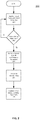
- FIG.2 depicts a flow chart showing the method for adjusting the correlation between a visual display perspective and a flight path of an aircraft 200 in accordance with one embodiment.
- the visual display of the aircraft initially provides a display at a default perspective 210.
- the default perspective depends on the emphasis of the current task in the phase of flight of the aircraft.
- the default view may be the current flight path orientation, the current heading orientation, etc.
- the display of the trajectory will take precedence. For example, as an aircraft begins an approach for a landing, the display will center on the landing target. Conversely, if the current phase of flight demands heading as the more important measure (e.g., slow hovering of a helicopter), the display will center on the current heading of the aircraft.
- the system on board the aircraft 100 will determine the flight path, heading, attitude, etc. of the aircraft, the orientation of the visual display optimal for current phase of flight, and compare and determine if the two adequately correlate 212.
- the direction of travel is of primary importance. If sufficient correlation exists between the flight path in the visual display, the system will maintain the default perspective along the path. However, if the flight path and the default visual display differ significantly, the system will begin a transition of the visual display to reflect the flight path of the aircraft. In examples of a helicopter slowing down to hover operations, the optimal visual perspective or default perspective for the hover operations is the current heading orientation. As such, when visual perspective and default perspective differs significantly, the system will begin a transition of the visual display to the heading orientation.
- the current aircraft performance parameters are retrieved 214 by the sensor system 110, the navigation system 112 and the database 114.
- the aircraft performance parameters may include: the heading change rate of the aircraft ( i . e ., rate of turn); the lateral acceleration of the aircraft; the vertical acceleration of the aircraft; the yaw rate of the aircraft; the ground speed of the aircraft; etc.
- the performance parameters are collected by software module on board the aircraft and provided to the processor 102 of the system 100.
- the processor 102 determines the transition rate of the visual display to reflect the default view orientation such as flight path 216 or heading based on the performance parameters and transitions the visual display to reflect the flight path 218 or heading.
- the transition rate is measured in degrees per second in some embodiments.
- the transition rate may vary widely. For example, a transition rate of 1° per second is considered very slow while a transition rate of 20° per second is considered very fast. In some embodiments, the transition rate may be in the range from 5°-15° per second with a default rate of 10° per second. In other embodiments, the transition rate for a transition event needs not to be a fixed value.
- Achieving a smooth and natural transition between the display view and the aircraft heading is based on using the aircraft dynamics as the primary driving source for the transition rate. For example, if the aircraft parameter change rates or accelerations are small, the display view transition will happen slowly over a longer period. Conversely, a large changing rate of the parameters typically results in a quicker change of display perspectives. The overall goal is avoiding pilot confusion and disorientation. In addition, a pilot of the aircraft may manually select the transition rate based on personal preference.
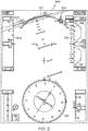
- FIG. 3 depicts a visual display for helicopter in accordance with an exemplary embodiment. If the flight path information can be accurately displayed at the default perspective 212, the method 200 will continue displaying at the default perspective 210. The method 200 will also continue to receive the flight path information and continue to evaluate the flight path information within the default perspective on an ongoing basis.
- the flight path information is represented by marker 304, which is not an accurate representation of the true flight path relative to the background 310.
- the flight path marker 304 provides a general guidance, but it is not accurate as indicated to the pilot by its dashed/ghosted nature. This discrepancy can potentially cause confusion for the pilot, and at the very least, fails to provide useful flight path information.
- the method 200 will proceed to retrieve current aircraft performance parameters 214, determine a transition rate 216, and transition the visual display to reflect the flight path 218.
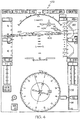
- a transitioned display 400 is shown in FIG. 4 with continued reference to FIG 3 .
- the background 410 has been shifted up and to the right.
- a marker 404 accurately indicates the flight path information relative to the displayed background 410.
- the transition from the default display 300 of FIG. 3 to the adjusted display 400 of FIG. 4 is smooth and natural so as not to disorient the pilot.
- the system 100 In determining the transition rate, the system 100 generally considers the angle and direction of the flight path information and ensures that the flight path marker 404 can be displayed relative to the background 410 within the viewing area of the display.
- the system 100 shifts the perspective in one or more of the horizontal and/or vertical directions to accommodate the angle and direction. This provides the flight crew with an accurate representation of the actual flight path information relative to the background 410. In an intuitive sense, this adjustment represents the action of a pilot turning his or her head to get a better view of the intended flight direction out of a window of a helicopter.
- the display mimics this perspective with the three-dimensional background 410 and the flight path information.
- the adjusted perspective can be indicated by the dashed nature of a zero-pitch reference line 402 or size, position, and color change of the aircraft symbol on the display. Certain textual annunciations or indications may also be provided.
- the display can be adjusted by increasing or decreasing the scaling of the perspective. In other words, the system 100 can "zoom out" such that the flight path information can be accurately displayed relative to the background 410.
- the perspective can be adjusted manually by the flight crew with the user input element 106.
- the method 200 can be particularly useful for displaying accurate flight path information during certain phases of flight, such as for example, take-off and landing.
- the flight path information can include current or intended flight path information and/or can include user-selected flight path information.
- exemplary methods may include additional or fewer steps or may be performed in the context of a larger processing scheme.
- the specific embodiments illustrated below are directed at helicopters, the methods and system may be used in various embodiments employing various types of displays, such as displays in space craft, aircraft, rotorcraft, and unmanned air vehicles (UAV).
- embodiments of the present invention are suitable for use on CRT, LCD, plasma displays or any other existing display technology.
- Skilled artisans may implement the described functionality in varying ways for each particular application, but such implementation decisions should not be interpreted as causing a departure from the scope of the present invention.
- an embodiment of a system or a component may employ various integrated circuit components, e.g., memory elements, digital signal processing elements, logic elements, look-up tables, or the like, which may carry out a variety of functions under the control of one or more microprocessors or other control devices.
- integrated circuit components e.g., memory elements, digital signal processing elements, logic elements, look-up tables, or the like, which may carry out a variety of functions under the control of one or more microprocessors or other control devices.
- DSP digital signal processor
- ASIC application specific integrated circuit
- FPGA field programmable gate array
- a general-purpose processor may be a microprocessor, but in the alternative, the processor may be any conventional processor, controller, microcontroller, or state machine.
- a processor may also be implemented as a combination of computing devices, e.g., a combination of a DSP and a microprocessor, a plurality of microprocessors, one or more microprocessors in conjunction with a DSP core, or any other such configuration.
- a software module may reside in RAM memory, flash memory, ROM memory, EPROM memory, EEPROM memory, registers, hard disk, a removable disk, a CD-ROM, or any other form of storage medium known in the art.
- An exemplary storage medium is coupled to the processor such that the processor can read information from, and write information to, the storage medium.
- the storage medium may be integral to the processor.
- the processor and the storage medium may reside in an ASIC.
- the ASIC may reside in a user terminal.
- the processor and the storage medium may reside as discrete components in a user terminal
Landscapes
- Engineering & Computer Science (AREA)
- Physics & Mathematics (AREA)
- General Physics & Mathematics (AREA)
- Radar, Positioning & Navigation (AREA)
- Remote Sensing (AREA)
- Aviation & Aerospace Engineering (AREA)
- Computer Networks & Wireless Communication (AREA)
- Theoretical Computer Science (AREA)
- Astronomy & Astrophysics (AREA)
- Signal Processing (AREA)
- Automation & Control Theory (AREA)
- Business, Economics & Management (AREA)
- Educational Administration (AREA)
- Educational Technology (AREA)
- Traffic Control Systems (AREA)
- Navigation (AREA)
Description
- The present invention generally relates to visual display systems for aircraft, and more particularly relates to a system and method for adjusting the correlation between visual display perspective and a flight path of an aircraft.
- Modern aircraft contain visual display systems that provide pilots and/or flight crews with substantial amounts of important navigation, operational and situational awareness information including information about the environment and terrain outside the aircraft. In fact, multi-functional aircraft displays can provide flight crews with computer-enhanced three-dimensional perspective images of terrain especially during conditions of low visibility. These images can include three-dimensional background and terrain information as well as graphics that represent pitch reference lines, airspeed, flight path information, altitude, attitude, etc. In some implementations, the terrain imagery of the background can be high resolution, computer-generated terrain image data derived from databases and onboard vision sensor systems.
- One problem with visual displays for aircraft is that the flight path of the aircraft and the perspective of the flight display may deviate significantly. This is particularly true for helicopters and other roto-aircraft. Typically, the flight display system will transition its' perspective to align with that of the true flight path of the aircraft. However, sudden changes in the displayed perspectives may lead to pilot disorientation.
EP2101155 discloses a visual display system including a visual display element configured to display a visual display with three-dimensional, conformal background information at a first perspective; and a processor coupled to the visual display.US2016/343260 discloses a system for displaying information related to a flight of an aircraft comprising a dynamic synthesis image generating module, configured to generate at least two successive transition synthesis images between an image according to a first type of perspective and an image according to a second type of perspective, or between an image according to a second type of perspective and an image according to a first type of perspective, respectively, and to command the display thereof at successive transition moments. Hence, there is a need for a system and method for adjusting the correlation between a visual display perspective and a flight path of an aircraft. - The invention is set out in accordance with the appended claims. This summary is provided to describe select concepts in a simplified form that are further described in the Detailed Description. This summary is not intended to identify key or essential features of the claimed subject matter, nor is it intended to be used as an aid in determining the scope of the claimed subject matter.
- A method is provided for a method for adjusting any correlation between a visual display perspective and a default display view of an aircraft. The method comprises: determining the default display view for an inflight aircraft; determining the current orientation of the visual display for the crew of the inflight aircraft; comparing the default display view with the orientation of the visual display to determine if the visual display's perspective needs to transition to reflect the default display view; and selecting a rate of transition of the visual display's perspective that is based on current aircraft performance parameters
- A system is provided for adjusting any correlation between an onboard visual display perspective and a flight path of an in-flight aircraft. The system comprises: a display element that provides a visual display for the crew of the in-flight aircraft; a sensor system that determines the flight path for the in-flight aircraft and current aircraft performance parameters; and a processor in operable communication with the display element and the sensor system, the processor configured to compare the flight path with the orientation of the visual display to determine if the visual display perspective needs to transition to reflect the flight path, where the processor selects a rate of transition of the visual display's perspective based on the current aircraft performance parameters.
- Furthermore, other desirable features and characteristics of the system and method will become apparent from the subsequent detailed description and the appended claims, taken in conjunction with the accompanying drawings and the preceding background.
- The present invention will hereinafter be described in conjunction with the following drawing figures, wherein like numerals denote like elements, and wherein:
-
FIG. 1 depicts a block diagram of a visual display system in accordance with an exemplary embodiment; -
FIG.2 depicts a flow chart showing the method for adjusting the correlation between a visual display perspective and a flight path of an aircraft in accordance with an exemplary embodiment; -
FIG.3 depicts a visual display for helicopter in accordance with an exemplary embodiment; and -
FIG. 4 depicts a visual display for helicopter that has been adjusted relative to the display shown inFIG. 3 in accordance with an exemplary embodiment. - The following detailed description is merely exemplary in nature and is not intended to limit the invention or the application and uses of the invention. As used herein, the word "exemplary" means "serving as an example, instance, or illustration." Thus, any embodiment described herein as "exemplary" is not necessarily to be construed as preferred or advantageous over other embodiments. All the embodiments described herein are exemplary embodiments provided to enable persons skilled in the art to make or use the invention and not to limit the scope of the invention which is defined by the claims. Furthermore, there is no intention to be bound by any expressed or implied theory presented in the preceding technical field, background, brief summary, or the following detailed description.
- A system and method for adjusting the correlation between the visual display perspective of an aircraft and its flight path have been developed. Embodiments of the present system and method provide for adjusting the correlation between the visual display and the flight path of an aircraft in a smooth and natural transition process. The transition is based on aircraft performance parameters and intended to avoid unexpected pilot responses or disorientation.
-
FIG. 1 depicts a block diagram of avisual display system 100 for an aircraft, such as a helicopter or other type of aircraft, in accordance with an exemplary embodiment. Thesystem 100 includes aprocessor 102, auser input element 106, avisual display element 108, asensor system 110, anavigation system 112, and adatabase 114, which are coupled to one another with a high-speeddata communications bus 104 or another connection scheme. Theprocessor 102,user input element 106,display element 108,sensor system 110,navigation system 112, anddatabase 114 can be individual components or integrated with one another, either onboard or external to the aircraft. Also, for example,system 100 can be arranged as an integrated system (e.g., aircraft display system, PFD system, etc.) or a subsystem of a more comprehensive aircraft system (e.g., Flight Management System, navigation and control system, target aiming and control system, collision alert and/or avoidance system, weather avoidance system, etc.). The various components of thesystem 100 will be generally described first and then followed by a more detailed explanation of their relationship to exemplary embodiments. - The
processor 102 can be a computer processor such as, for example, a microprocessor, digital signal processor, or any suitable processor capable of at least receiving and/or retrieving aircraft status information, navigation and control information (e.g., fromnavigation system 112 and/or sensor system 110), and high resolution terrain information (e.g., fromdatabase 114 and sensor system 110), and generating suitable display control signals for thedisplay element 108. The display control signals can be used to generate a display with, for example, aircraft status information, navigation and control information (including, for example, a zero-pitch reference line, heading indicators, tapes for airspeed and altitude, flight path information or similar type of aircraft aiming symbol, etc.), and three-dimensional terrain and other background information. As discussed in greater detail below, theprocessor 102 can include algorithms that can compare the current or intended flight path information to the background information at a particular perspective, and dynamically adjust the display signals such that the flight path information can be accurately displayed. - The
database 114 can be a memory device (e.g., non-volatile memory, disk, drive, tape, optical storage device, mass storage device, etc.). Thedatabase 114 can include terrain and other background information stored as either absolute coordinate data or as a function of an aircraft's position. Thedatabase 114 can include, for example, the locations and elevations of natural terrain obstacles such as mountains or other elevated ground areas; the locations and elevations of man-made obstacles such as radio antenna towers, buildings, bridges, etc.; boundaries and elevations of restricted airspace; and navigation data such as localized targets, runways, navigational waypoints, and position beacons. - The
sensor system 110 can include one or more visual sensors and other types of sensors that provide information for thedatabase 114 and/orprocessor 102. The information provided by thesensor system 110 can include navigation and control information, as well as background and terrain information. - The
navigation system 112 can provide navigation data associated with the aircraft's current status, position and flight direction (e.g., heading, course, track, attitude, and any flight path information.) to theprocessor 102. Thenavigation system 112 can form part of a larger flight management system and can include, for example, an inertial navigation system, and a satellite navigation system (e.g., Global Positioning System). For one exemplary embodiment, thenavigation system 112 can include suitable position and direction determination devices that can provide theprocessor 102 with at least an aircraft's current position (e.g., in latitudinal and longitudinal form), the real-time direction (e.g., heading, course, track, etc.) of the aircraft in its flight path, and other important flight information (e.g., pitch, airspeed, altitude, attitude, etc.). - The
display element 108 may include any device or apparatus suitable for displaying various types of computer-generated symbols and information representing, for example, natural and man-made terrain and other background information, pitch, heading, flight path, airspeed, altitude, attitude, target data, flight path marker data, and any type of flight path information in an integrated, multi-color or monochrome form (e.g., flat-panel color display). Although a cockpit display screen may be used to display the above-described flight information and terrain symbols and data, exemplary embodiments discussed herein are not intended to be so limited and can include any suitable type of display medium capable of visually presenting multi-colored or monochrome flight information and terrain symbols and data for a pilot or other flight crew member, and in particular, but not exclusively, on a continuous, three-dimensional perspective view aircraft display. As such, many known display monitors are suitable for displaying such information, symbols and data, such as, for example, various CRT and flat-panel display systems (e.g., CRT displays, LCDs, OLED displays, plasma displays, projection displays, HDDs, Heads-Up Displays/HUDs, etc.). - The
user input element 106 includes, but is not limited to, keyboards, pointer devices, touch screens, microphones, etc. In some embodiments, theuser input element 106 includes more than one type of input element. In other embodiments, thesystem 100 does not include anyuser input element 106, and/or theuser input element 106 is only used to override automated functions of thesystem 100. -
FIG.2 , with continued reference toFIG. 1 , depicts a flow chart showing the method for adjusting the correlation between a visual display perspective and a flight path of anaircraft 200 in accordance with one embodiment. The visual display of the aircraft initially provides a display at adefault perspective 210. The default perspective depends on the emphasis of the current task in the phase of flight of the aircraft. For example, the default view may be the current flight path orientation, the current heading orientation, etc. If the trajectory of the aircraft is more important at the current phase of flight than the current heading, the display of the trajectory will take precedence. For example, as an aircraft begins an approach for a landing, the display will center on the landing target. Conversely, if the current phase of flight demands heading as the more important measure (e.g., slow hovering of a helicopter), the display will center on the current heading of the aircraft. - The system on board the
aircraft 100 will determine the flight path, heading, attitude, etc. of the aircraft, the orientation of the visual display optimal for current phase of flight, and compare and determine if the two adequately correlate 212. In the example of an aircraft flying along a path at certain speed, the direction of travel is of primary importance. If sufficient correlation exists between the flight path in the visual display, the system will maintain the default perspective along the path. However, if the flight path and the default visual display differ significantly, the system will begin a transition of the visual display to reflect the flight path of the aircraft. In examples of a helicopter slowing down to hover operations, the optimal visual perspective or default perspective for the hover operations is the current heading orientation. As such, when visual perspective and default perspective differs significantly, the system will begin a transition of the visual display to the heading orientation. - If a transition is required, the current aircraft performance parameters are retrieved 214 by the
sensor system 110, thenavigation system 112 and thedatabase 114. The aircraft performance parameters may include: the heading change rate of the aircraft (i.e., rate of turn); the lateral acceleration of the aircraft; the vertical acceleration of the aircraft; the yaw rate of the aircraft; the ground speed of the aircraft; etc. The performance parameters are collected by software module on board the aircraft and provided to theprocessor 102 of thesystem 100. Theprocessor 102 determines the transition rate of the visual display to reflect the default view orientation such asflight path 216 or heading based on the performance parameters and transitions the visual display to reflect theflight path 218 or heading. - The transition rate is measured in degrees per second in some embodiments. The transition rate may vary widely. For example, a transition rate of 1° per second is considered very slow while a transition rate of 20° per second is considered very fast. In some embodiments, the transition rate may be in the range from 5°-15° per second with a default rate of 10° per second. In other embodiments, the transition rate for a transition event needs not to be a fixed value.
- Achieving a smooth and natural transition between the display view and the aircraft heading is based on using the aircraft dynamics as the primary driving source for the transition rate. For example, if the aircraft parameter change rates or accelerations are small, the display view transition will happen slowly over a longer period. Conversely, a large changing rate of the parameters typically results in a quicker change of display perspectives. The overall goal is avoiding pilot confusion and disorientation. In addition, a pilot of the aircraft may manually select the transition rate based on personal preference.
-
FIG. 3 , with continued reference toFIGS. 1 and2 , depicts a visual display for helicopter in accordance with an exemplary embodiment. If the flight path information can be accurately displayed at thedefault perspective 212, themethod 200 will continue displaying at thedefault perspective 210. Themethod 200 will also continue to receive the flight path information and continue to evaluate the flight path information within the default perspective on an ongoing basis. - However, the example depicted by
FIG. 3 shows the helicopter is taking off and the actual flight path is almost straight up. As such, the flight path information is at too great an angle to be represented accurately on the limited dimensions of the display. InFIG. 3 , the flight path information is represented bymarker 304, which is not an accurate representation of the true flight path relative to thebackground 310. Theflight path marker 304 provides a general guidance, but it is not accurate as indicated to the pilot by its dashed/ghosted nature. This discrepancy can potentially cause confusion for the pilot, and at the very least, fails to provide useful flight path information. - If confronted with a situation shown in
FIG. 3 , themethod 200 will proceed to retrieve currentaircraft performance parameters 214, determine atransition rate 216, and transition the visual display to reflect theflight path 218. A transitioneddisplay 400 is shown inFIG. 4 with continued reference toFIG 3 . As a result of the transition, thebackground 410 has been shifted up and to the right. Amarker 404 accurately indicates the flight path information relative to the displayedbackground 410. The transition from thedefault display 300 ofFIG. 3 to the adjusteddisplay 400 ofFIG. 4 is smooth and natural so as not to disorient the pilot. Although the examples shown inFIGS. 3 and4 use the vertical component of the flight path to indicate the transition process controlled by using aircraft dynamic parameters, it should be understood that such a controlled transition can be applied to the lateral direction component of the flight path (ground track), when the default view is transitioned from heading to or from current ground track directions - In determining the transition rate, the
system 100 generally considers the angle and direction of the flight path information and ensures that theflight path marker 404 can be displayed relative to thebackground 410 within the viewing area of the display. Thesystem 100 shifts the perspective in one or more of the horizontal and/or vertical directions to accommodate the angle and direction. This provides the flight crew with an accurate representation of the actual flight path information relative to thebackground 410. In an intuitive sense, this adjustment represents the action of a pilot turning his or her head to get a better view of the intended flight direction out of a window of a helicopter. The display mimics this perspective with the three-dimensional background 410 and the flight path information. The adjusted perspective can be indicated by the dashed nature of a zero-pitch reference line 402 or size, position, and color change of the aircraft symbol on the display. Certain textual annunciations or indications may also be provided. In other embodiments, the display can be adjusted by increasing or decreasing the scaling of the perspective. In other words, thesystem 100 can "zoom out" such that the flight path information can be accurately displayed relative to thebackground 410. In an alternate embodiment, the perspective can be adjusted manually by the flight crew with theuser input element 106. - As noted above, the
method 200 can be particularly useful for displaying accurate flight path information during certain phases of flight, such as for example, take-off and landing. The flight path information can include current or intended flight path information and/or can include user-selected flight path information. It should also be understood that exemplary methods may include additional or fewer steps or may be performed in the context of a larger processing scheme. Furthermore, it will be understood by one of skill in the art that although the specific embodiments illustrated below are directed at helicopters, the methods and system may be used in various embodiments employing various types of displays, such as displays in space craft, aircraft, rotorcraft, and unmanned air vehicles (UAV). Moreover, embodiments of the present invention are suitable for use on CRT, LCD, plasma displays or any other existing display technology. - Those of skill in the art will appreciate that the various illustrative logical blocks, modules, circuits, and algorithm steps described in connection with the embodiments disclosed herein may be implemented as electronic hardware, computer software, or combinations of both. Some of the embodiments and implementations are described above in terms of functional and/or logical block components (or modules) and various processing steps. However, it should be appreciated that such block components (or modules) may be realized by any number of hardware, software, and/or firmware components configured to perform the specified functions. To clearly illustrate this interchangeability of hardware and software, various illustrative components, blocks, modules, circuits, and steps have been described above generally in terms of their functionality. Whether such functionality is implemented as hardware or software depends upon the particular application and design constraints imposed on the overall system. Skilled artisans may implement the described functionality in varying ways for each particular application, but such implementation decisions should not be interpreted as causing a departure from the scope of the present invention. For example, an embodiment of a system or a component may employ various integrated circuit components, e.g., memory elements, digital signal processing elements, logic elements, look-up tables, or the like, which may carry out a variety of functions under the control of one or more microprocessors or other control devices. In addition, those skilled in the art will appreciate that embodiments described herein are merely exemplary implementations.
- The various illustrative logical blocks, modules, and circuits described in connection with the embodiments disclosed herein may be implemented or performed with a general purpose processor, a digital signal processor (DSP), an application specific integrated circuit (ASIC), a field programmable gate array (FPGA) or other programmable logic device, discrete gate or transistor logic, discrete hardware components, or any combination thereof designed to perform the functions described herein. A general-purpose processor may be a microprocessor, but in the alternative, the processor may be any conventional processor, controller, microcontroller, or state machine. A processor may also be implemented as a combination of computing devices, e.g., a combination of a DSP and a microprocessor, a plurality of microprocessors, one or more microprocessors in conjunction with a DSP core, or any other such configuration.
- The steps of a method or algorithm described in connection with the embodiments disclosed herein may be embodied directly in hardware, in a software module executed by a processor, or in a combination of the two. A software module may reside in RAM memory, flash memory, ROM memory, EPROM memory, EEPROM memory, registers, hard disk, a removable disk, a CD-ROM, or any other form of storage medium known in the art. An exemplary storage medium is coupled to the processor such that the processor can read information from, and write information to, the storage medium. In the alternative, the storage medium may be integral to the processor. The processor and the storage medium may reside in an ASIC. The ASIC may reside in a user terminal. In the alternative, the processor and the storage medium may reside as discrete components in a user terminal
- In this document, relational terms such as first and second, and the like may be used solely to distinguish one entity or action from another entity or action without necessarily requiring or implying any actual such relationship or order between such entities or actions. Numerical ordinals such as "first," "second," "third," etc. simply denote different singles of a plurality and do not imply any order or sequence unless specifically defined by the claim language. The sequence of the text in any of the claims does not imply that process steps must be performed in a temporal or logical order according to such sequence unless it is specifically defined by the language of the claim. The process steps may be interchanged in any order without departing from the scope of the invention as long as such an interchange does not contradict the claim language and is not logically nonsensical.
- Furthermore, depending on the context, words such as "connect" or "coupled to" used in describing a relationship between different elements do not imply that a direct physical connection must be made between these elements. For example, two elements may be connected to each other physically, electronically, logically, or in any other manner, through one or more additional elements.
- While at least one exemplary embodiment has been presented in the foregoing detailed description of the invention, it should be appreciated that a vast number of variations exist. It should also be appreciated that the exemplary embodiment or exemplary embodiments are only examples, and are not intended to limit the scope, applicability, or configuration of the invention in any way. Rather, the foregoing detailed description will provide those skilled in the art with a convenient road map for implementing an exemplary embodiment of the invention. It being understood that various changes may be made in the function and arrangement of elements described in an exemplary embodiment without departing from the scope of the invention as set forth in the appended claims.
Claims (13)
- A method, performed by a processor located on board an inflight aircraft, for adjusting any correlation between a current perspective of a visual display and a default perspective of the visual display of the inflight aircraft, comprising:determining the default perspective (210) of the visual display for the inflight aircraft;determining the current perspective (210) of the visual display for the crew of the inflight aircraft;comparing the default perspective of the visual display with the current perspective of the visual display to determine if the current perspective of the visual display needs to transition (212) to reflect the default perspective of the visual display;characterized by:selecting a rate of transition (216) of the current perspective of the visual display that is based on current aircraft performance parameters (214); andtransitioning the current perspective of the visual display (218) to reflect the default perspective of the visual display at the selected rate of transition.
- The method of Claim 1, where the default perspective of the visual display is the current flight path.
- The method of Claim 1, where the default perspective of the visual display is the current heading orientation.
- The method of Claim 1, where the current aircraft performance parameters comprise a heading change rate of the aircraft.
- The method of Claim 1, where the current aircraft performance parameters comprise lateral acceleration of the aircraft.
- The method of Claim 1, where the current aircraft performance parameters comprise vertical acceleration of the aircraft.
- The method of Claim 1, where the current aircraft performance parameters comprise yaw rate of the aircraft.
- The method of Claim 1, where the current aircraft performance parameters comprise ground speed of the aircraft.
- The method of Claim 1, where the rate of transition is from 1°- 20° per second.
- The method of Claim 1, where the rate of transition is from 5° - 15° per second.
- The method of Claim 1, where the rate of transition is approximately 10° per second.
- The method of Claim 1, where a pilot of the aircraft takes over the selecting a rate of transition and manually selecting the rate of transition based on personal preference.
- A system for adjusting any correlation between a current perspective of a visual display and a flight path of an in-flight aircraft, comprising:a display element (108) that provides a visual display for the crew of the in-flight aircraft;a sensor system (110) that determines the flight path for the in-flight aircraft and current aircraft performance parameters; anda processor (102) in operable communication (104) with the display element (108) and the sensor system (110), characterized by the processor (102) configured to compare the flight path with the current perspective of the visual display to determine if the current perspective of the visual display needs to transition to reflect the flight path, characterised in that the processor (102) selects and implements a rate of transition of the current perspective of the visual display based on the current aircraft performance parameters.
Applications Claiming Priority (1)
| Application Number | Priority Date | Filing Date | Title |
|---|---|---|---|
| US15/607,835 US10332413B2 (en) | 2017-05-30 | 2017-05-30 | System and method for adjusting the correlation between a visual display perspective and a flight path of an aircraft |
Publications (2)
| Publication Number | Publication Date |
|---|---|
| EP3410073A1 EP3410073A1 (en) | 2018-12-05 |
| EP3410073B1 true EP3410073B1 (en) | 2020-05-13 |
Family
ID=62186301
Family Applications (1)
| Application Number | Title | Priority Date | Filing Date |
|---|---|---|---|
| EP18172516.9A Active EP3410073B1 (en) | 2017-05-30 | 2018-05-15 | System and method for adjusting the correlation between a visual display perspective and a flight path of an aircraft |
Country Status (3)
| Country | Link |
|---|---|
| US (2) | US10332413B2 (en) |
| EP (1) | EP3410073B1 (en) |
| CN (1) | CN108983796B (en) |
Families Citing this family (6)
| Publication number | Priority date | Publication date | Assignee | Title |
|---|---|---|---|---|
| WO2016149039A1 (en) * | 2015-03-17 | 2016-09-22 | Sikorsky Aircraft Corporation | Trajectory control of a vehicle |
| US10332413B2 (en) * | 2017-05-30 | 2019-06-25 | Honeywell International Inc. | System and method for adjusting the correlation between a visual display perspective and a flight path of an aircraft |
| AU2018241119A1 (en) * | 2017-10-06 | 2019-05-02 | Tata Consultancy Services Limited | System and method for flight delay prediction |
| US11267555B2 (en) * | 2018-01-08 | 2022-03-08 | GEOSAT Aerospace & Technology | Methods and unmanned aerial vehicles for longer duration flights |
| JP6557887B1 (en) | 2019-01-07 | 2019-08-14 | 修二 山口 | Tooth moving instruments |
| CN112185172B (en) * | 2019-07-01 | 2024-03-26 | 波音公司 | Aircraft flight information system and method |
Family Cites Families (30)
| Publication number | Priority date | Publication date | Assignee | Title |
|---|---|---|---|---|
| FR2666428B1 (en) * | 1990-09-05 | 1994-09-23 | Aerospatiale | METHOD OF VIEWING ON A SCREEN ON BOARD AN AIRPLANE, SYMBOLS FOR PILOTAGE. |
| US5614897A (en) | 1995-03-29 | 1997-03-25 | The Secretary Of State For Defence In Her Britannic Majesty's Government Of The United Kingdom Of Great Britain And Northern Ireland | Aircraft flight instrument displays |
| US5978715A (en) * | 1997-10-15 | 1999-11-02 | Dassault Aviation | Apparatus and method for aircraft display and control |
| US6112141A (en) * | 1997-10-15 | 2000-08-29 | Dassault Aviation | Apparatus and method for graphically oriented aircraft display and control |
| US6038498A (en) * | 1997-10-15 | 2000-03-14 | Dassault Aviation | Apparatus and mehod for aircraft monitoring and control including electronic check-list management |
| US6057786A (en) * | 1997-10-15 | 2000-05-02 | Dassault Aviation | Apparatus and method for aircraft display and control including head up display |
| AU6488400A (en) | 1999-04-01 | 2000-11-10 | Ricardo A. Price | Electronic flight instrument displays |
| US6486799B1 (en) | 1999-07-19 | 2002-11-26 | The University Of West Florida | Computer based human-centered display system |
| DE19955664C2 (en) * | 1999-11-19 | 2003-07-17 | Eads Deutschland Gmbh | Flight guidance display for use in aircraft cockpit and aircraft simulation systems |
| US8132117B2 (en) | 2002-07-08 | 2012-03-06 | Innovative Solutions And Support, Inc. | Method and system for highlighting an image representative of a flight parameter of an aircraft |
| US7604595B2 (en) | 2004-06-22 | 2009-10-20 | General Electric Company | Method and system for performing real time navigation of ultrasound volumetric data |
| US7307549B2 (en) * | 2005-07-05 | 2007-12-11 | Gulfstream Aerospace Corporation | Standby display aircraft management system |
| US7908078B2 (en) | 2005-10-13 | 2011-03-15 | Honeywell International Inc. | Perspective-view visual runway awareness and advisory display |
| US8339284B2 (en) | 2008-03-11 | 2012-12-25 | Honeywell International Inc. | Method and apparatus for displaying flight path information in rotocraft |
| US8195347B2 (en) * | 2009-05-28 | 2012-06-05 | The Boeing Company | Method and system for approach decision display |
| US8767040B2 (en) * | 2012-01-11 | 2014-07-01 | Google Inc. | Method and system for displaying panoramic imagery |
| FR2988510B1 (en) | 2012-03-20 | 2015-07-24 | Airbus Operations Sas | METHOD AND DEVICE FOR DISPLAYING METEOROLOGICAL INFORMATION ON AN AIRCRAFT SCREEN |
| US9377325B2 (en) * | 2013-03-18 | 2016-06-28 | Honeywell International Inc. | System and method for graphically displaying airspace speed data |
| US9047771B1 (en) * | 2014-03-07 | 2015-06-02 | The Boeing Company | Systems and methods for ground collision avoidance |
| JP6293304B2 (en) * | 2014-05-21 | 2018-03-14 | エスゼット ディージェイアイ テクノロジー カンパニー リミテッドSz Dji Technology Co.,Ltd | Remote control device, control system, and control method |
| FR3029618B1 (en) | 2014-12-05 | 2019-09-27 | Thales | SYSTEM FOR SYNTHETIC VISUALIZATION COMPRISING LANDSCAPE ADAPTATION MEANS DISPLAY |
| US10053226B2 (en) * | 2014-12-24 | 2018-08-21 | Environmental Tectonics Corp. | Aircraft-vision systems and methods for maintaining situational awareness and spatial orientation |
| FR3031585B1 (en) * | 2015-01-08 | 2020-01-10 | Airbus Operations | METHOD AND DEVICE FOR AIDING THE PILOTAGE OF AN AIRCRAFT, AT LEAST ONE FLIGHT PHASE HAVING A PLURALITY OF STEPPING STEPS. |
| US9581465B2 (en) * | 2015-01-20 | 2017-02-28 | Honeywell International Inc. | Apparatus and method for displaying a synthetic vision system view direction |
| WO2016149039A1 (en) * | 2015-03-17 | 2016-09-22 | Sikorsky Aircraft Corporation | Trajectory control of a vehicle |
| FR3036511B1 (en) | 2015-05-19 | 2019-12-20 | Dassault Aviation | SYSTEM FOR VIEWING INFORMATION RELATING TO AN AIRCRAFT FLIGHT AND ASSOCIATED METHOD |
| CN104950695B (en) * | 2015-07-15 | 2018-02-27 | 浙江工业大学 | A kind of general unmanned plane vision emulation platform |
| CN105391988A (en) * | 2015-12-11 | 2016-03-09 | 谭圆圆 | Multi-view unmanned aerial vehicle and multi-view display method thereof |
| US10388171B2 (en) * | 2017-02-15 | 2019-08-20 | Honeywell International Inc. | Cockpit display systems and methods for generating cockpit displays including direct approach energy management symbology |
| US10332413B2 (en) * | 2017-05-30 | 2019-06-25 | Honeywell International Inc. | System and method for adjusting the correlation between a visual display perspective and a flight path of an aircraft |
-
2017
- 2017-05-30 US US15/607,835 patent/US10332413B2/en active Active
-
2018
- 2018-05-15 EP EP18172516.9A patent/EP3410073B1/en active Active
- 2018-05-29 CN CN201810530216.7A patent/CN108983796B/en active Active
-
2019
- 2019-05-20 US US16/417,215 patent/US11056018B2/en active Active
Non-Patent Citations (1)
| Title |
|---|
| None * |
Also Published As
| Publication number | Publication date |
|---|---|
| CN108983796B (en) | 2023-09-26 |
| CN108983796A (en) | 2018-12-11 |
| US11056018B2 (en) | 2021-07-06 |
| US20180350258A1 (en) | 2018-12-06 |
| US20190311646A1 (en) | 2019-10-10 |
| EP3410073A1 (en) | 2018-12-05 |
| US10332413B2 (en) | 2019-06-25 |
Similar Documents
| Publication | Publication Date | Title |
|---|---|---|
| EP2899509B1 (en) | System and method for displaying flight path information in rotocraft | |
| EP2101155B1 (en) | Method and apparatus for displaying flight path information in rotorcraft | |
| EP3410073B1 (en) | System and method for adjusting the correlation between a visual display perspective and a flight path of an aircraft | |
| EP2993655B1 (en) | Aircraft systems and methods for displaying spacing information | |
| EP2182325B1 (en) | Aircraft display system for display of flight path information | |
| EP2696171B1 (en) | Aircraft systems and methods for displaying weather information along a flight path | |
| EP2148176B1 (en) | Aircraft display system with obstacle warning envelope | |
| EP3444570B1 (en) | Aircraft systems and methods for unusual attitude recovery | |
| EP3029419B1 (en) | System and method for aiding a pilot in locating an out of view landing site | |
| EP2154484B1 (en) | Method and system for operating a display device on-board an aircraft | |
| EP1959239A1 (en) | Target zone display system and method | |
| EP2613125B1 (en) | System and method for indicating a perspective cockpit field-of-view on a vertical situation display | |
| EP2679961A2 (en) | Aircraft systems and methods for attitude recovery | |
| EP2846134B1 (en) | Helicopter system and method for integrating collective flight director cues | |
| EP3309518B1 (en) | System and method for generating and displaying an aircraft orientation cue |
Legal Events
| Date | Code | Title | Description |
|---|---|---|---|
| PUAI | Public reference made under article 153(3) epc to a published international application that has entered the european phase |
Free format text: ORIGINAL CODE: 0009012 |
|
| STAA | Information on the status of an ep patent application or granted ep patent |
Free format text: STATUS: REQUEST FOR EXAMINATION WAS MADE |
|
| 17P | Request for examination filed |
Effective date: 20180515 |
|
| AK | Designated contracting states |
Kind code of ref document: A1 Designated state(s): AL AT BE BG CH CY CZ DE DK EE ES FI FR GB GR HR HU IE IS IT LI LT LU LV MC MK MT NL NO PL PT RO RS SE SI SK SM TR |
|
| AX | Request for extension of the european patent |
Extension state: BA ME |
|
| RIC1 | Information provided on ipc code assigned before grant |
Ipc: H04B 7/185 20060101ALI20191108BHEP Ipc: G01C 23/00 20060101AFI20191108BHEP |
|
| GRAP | Despatch of communication of intention to grant a patent |
Free format text: ORIGINAL CODE: EPIDOSNIGR1 |
|
| STAA | Information on the status of an ep patent application or granted ep patent |
Free format text: STATUS: GRANT OF PATENT IS INTENDED |
|
| INTG | Intention to grant announced |
Effective date: 20200103 |
|
| GRAS | Grant fee paid |
Free format text: ORIGINAL CODE: EPIDOSNIGR3 |
|
| GRAA | (expected) grant |
Free format text: ORIGINAL CODE: 0009210 |
|
| STAA | Information on the status of an ep patent application or granted ep patent |
Free format text: STATUS: THE PATENT HAS BEEN GRANTED |
|
| AK | Designated contracting states |
Kind code of ref document: B1 Designated state(s): AL AT BE BG CH CY CZ DE DK EE ES FI FR GB GR HR HU IE IS IT LI LT LU LV MC MK MT NL NO PL PT RO RS SE SI SK SM TR |
|
| REG | Reference to a national code |
Ref country code: GB Ref legal event code: FG4D |
|
| REG | Reference to a national code |
Ref country code: CH Ref legal event code: EP |
|
| REG | Reference to a national code |
Ref country code: DE Ref legal event code: R096 Ref document number: 602018004391 Country of ref document: DE |
|
| REG | Reference to a national code |
Ref country code: AT Ref legal event code: REF Ref document number: 1270877 Country of ref document: AT Kind code of ref document: T Effective date: 20200615 |
|
| REG | Reference to a national code |
Ref country code: LT Ref legal event code: MG4D |
|
| REG | Reference to a national code |
Ref country code: NL Ref legal event code: MP Effective date: 20200513 |
|
| PG25 | Lapsed in a contracting state [announced via postgrant information from national office to epo] |
Ref country code: LT Free format text: LAPSE BECAUSE OF FAILURE TO SUBMIT A TRANSLATION OF THE DESCRIPTION OR TO PAY THE FEE WITHIN THE PRESCRIBED TIME-LIMIT Effective date: 20200513 Ref country code: GR Free format text: LAPSE BECAUSE OF FAILURE TO SUBMIT A TRANSLATION OF THE DESCRIPTION OR TO PAY THE FEE WITHIN THE PRESCRIBED TIME-LIMIT Effective date: 20200814 Ref country code: NO Free format text: LAPSE BECAUSE OF FAILURE TO SUBMIT A TRANSLATION OF THE DESCRIPTION OR TO PAY THE FEE WITHIN THE PRESCRIBED TIME-LIMIT Effective date: 20200813 Ref country code: IS Free format text: LAPSE BECAUSE OF FAILURE TO SUBMIT A TRANSLATION OF THE DESCRIPTION OR TO PAY THE FEE WITHIN THE PRESCRIBED TIME-LIMIT Effective date: 20200913 Ref country code: PT Free format text: LAPSE BECAUSE OF FAILURE TO SUBMIT A TRANSLATION OF THE DESCRIPTION OR TO PAY THE FEE WITHIN THE PRESCRIBED TIME-LIMIT Effective date: 20200914 Ref country code: SE Free format text: LAPSE BECAUSE OF FAILURE TO SUBMIT A TRANSLATION OF THE DESCRIPTION OR TO PAY THE FEE WITHIN THE PRESCRIBED TIME-LIMIT Effective date: 20200513 Ref country code: FI Free format text: LAPSE BECAUSE OF FAILURE TO SUBMIT A TRANSLATION OF THE DESCRIPTION OR TO PAY THE FEE WITHIN THE PRESCRIBED TIME-LIMIT Effective date: 20200513 |
|
| PG25 | Lapsed in a contracting state [announced via postgrant information from national office to epo] |
Ref country code: HR Free format text: LAPSE BECAUSE OF FAILURE TO SUBMIT A TRANSLATION OF THE DESCRIPTION OR TO PAY THE FEE WITHIN THE PRESCRIBED TIME-LIMIT Effective date: 20200513 Ref country code: LV Free format text: LAPSE BECAUSE OF FAILURE TO SUBMIT A TRANSLATION OF THE DESCRIPTION OR TO PAY THE FEE WITHIN THE PRESCRIBED TIME-LIMIT Effective date: 20200513 Ref country code: BG Free format text: LAPSE BECAUSE OF FAILURE TO SUBMIT A TRANSLATION OF THE DESCRIPTION OR TO PAY THE FEE WITHIN THE PRESCRIBED TIME-LIMIT Effective date: 20200813 Ref country code: RS Free format text: LAPSE BECAUSE OF FAILURE TO SUBMIT A TRANSLATION OF THE DESCRIPTION OR TO PAY THE FEE WITHIN THE PRESCRIBED TIME-LIMIT Effective date: 20200513 |
|
| REG | Reference to a national code |
Ref country code: AT Ref legal event code: MK05 Ref document number: 1270877 Country of ref document: AT Kind code of ref document: T Effective date: 20200513 |
|
| PG25 | Lapsed in a contracting state [announced via postgrant information from national office to epo] |
Ref country code: AL Free format text: LAPSE BECAUSE OF FAILURE TO SUBMIT A TRANSLATION OF THE DESCRIPTION OR TO PAY THE FEE WITHIN THE PRESCRIBED TIME-LIMIT Effective date: 20200513 Ref country code: NL Free format text: LAPSE BECAUSE OF FAILURE TO SUBMIT A TRANSLATION OF THE DESCRIPTION OR TO PAY THE FEE WITHIN THE PRESCRIBED TIME-LIMIT Effective date: 20200513 |
|
| PG25 | Lapsed in a contracting state [announced via postgrant information from national office to epo] |
Ref country code: SM Free format text: LAPSE BECAUSE OF FAILURE TO SUBMIT A TRANSLATION OF THE DESCRIPTION OR TO PAY THE FEE WITHIN THE PRESCRIBED TIME-LIMIT Effective date: 20200513 Ref country code: EE Free format text: LAPSE BECAUSE OF FAILURE TO SUBMIT A TRANSLATION OF THE DESCRIPTION OR TO PAY THE FEE WITHIN THE PRESCRIBED TIME-LIMIT Effective date: 20200513 Ref country code: CZ Free format text: LAPSE BECAUSE OF FAILURE TO SUBMIT A TRANSLATION OF THE DESCRIPTION OR TO PAY THE FEE WITHIN THE PRESCRIBED TIME-LIMIT Effective date: 20200513 Ref country code: RO Free format text: LAPSE BECAUSE OF FAILURE TO SUBMIT A TRANSLATION OF THE DESCRIPTION OR TO PAY THE FEE WITHIN THE PRESCRIBED TIME-LIMIT Effective date: 20200513 Ref country code: ES Free format text: LAPSE BECAUSE OF FAILURE TO SUBMIT A TRANSLATION OF THE DESCRIPTION OR TO PAY THE FEE WITHIN THE PRESCRIBED TIME-LIMIT Effective date: 20200513 Ref country code: AT Free format text: LAPSE BECAUSE OF FAILURE TO SUBMIT A TRANSLATION OF THE DESCRIPTION OR TO PAY THE FEE WITHIN THE PRESCRIBED TIME-LIMIT Effective date: 20200513 Ref country code: DK Free format text: LAPSE BECAUSE OF FAILURE TO SUBMIT A TRANSLATION OF THE DESCRIPTION OR TO PAY THE FEE WITHIN THE PRESCRIBED TIME-LIMIT Effective date: 20200513 Ref country code: IT Free format text: LAPSE BECAUSE OF FAILURE TO SUBMIT A TRANSLATION OF THE DESCRIPTION OR TO PAY THE FEE WITHIN THE PRESCRIBED TIME-LIMIT Effective date: 20200513 |
|
| REG | Reference to a national code |
Ref country code: DE Ref legal event code: R097 Ref document number: 602018004391 Country of ref document: DE |
|
| PG25 | Lapsed in a contracting state [announced via postgrant information from national office to epo] |
Ref country code: SK Free format text: LAPSE BECAUSE OF FAILURE TO SUBMIT A TRANSLATION OF THE DESCRIPTION OR TO PAY THE FEE WITHIN THE PRESCRIBED TIME-LIMIT Effective date: 20200513 Ref country code: MC Free format text: LAPSE BECAUSE OF FAILURE TO SUBMIT A TRANSLATION OF THE DESCRIPTION OR TO PAY THE FEE WITHIN THE PRESCRIBED TIME-LIMIT Effective date: 20200513 Ref country code: PL Free format text: LAPSE BECAUSE OF FAILURE TO SUBMIT A TRANSLATION OF THE DESCRIPTION OR TO PAY THE FEE WITHIN THE PRESCRIBED TIME-LIMIT Effective date: 20200513 |
|
| PLBE | No opposition filed within time limit |
Free format text: ORIGINAL CODE: 0009261 |
|
| REG | Reference to a national code |
Ref country code: BE Ref legal event code: MM Effective date: 20200531 |
|
| STAA | Information on the status of an ep patent application or granted ep patent |
Free format text: STATUS: NO OPPOSITION FILED WITHIN TIME LIMIT |
|
| PG25 | Lapsed in a contracting state [announced via postgrant information from national office to epo] |
Ref country code: LU Free format text: LAPSE BECAUSE OF NON-PAYMENT OF DUE FEES Effective date: 20200515 |
|
| 26N | No opposition filed |
Effective date: 20210216 |
|
| PG25 | Lapsed in a contracting state [announced via postgrant information from national office to epo] |
Ref country code: IE Free format text: LAPSE BECAUSE OF NON-PAYMENT OF DUE FEES Effective date: 20200515 |
|
| PG25 | Lapsed in a contracting state [announced via postgrant information from national office to epo] |
Ref country code: BE Free format text: LAPSE BECAUSE OF NON-PAYMENT OF DUE FEES Effective date: 20200531 Ref country code: SI Free format text: LAPSE BECAUSE OF FAILURE TO SUBMIT A TRANSLATION OF THE DESCRIPTION OR TO PAY THE FEE WITHIN THE PRESCRIBED TIME-LIMIT Effective date: 20200513 |
|
| REG | Reference to a national code |
Ref country code: CH Ref legal event code: PL |
|
| PG25 | Lapsed in a contracting state [announced via postgrant information from national office to epo] |
Ref country code: LI Free format text: LAPSE BECAUSE OF NON-PAYMENT OF DUE FEES Effective date: 20210531 Ref country code: CH Free format text: LAPSE BECAUSE OF NON-PAYMENT OF DUE FEES Effective date: 20210531 |
|
| PG25 | Lapsed in a contracting state [announced via postgrant information from national office to epo] |
Ref country code: TR Free format text: LAPSE BECAUSE OF FAILURE TO SUBMIT A TRANSLATION OF THE DESCRIPTION OR TO PAY THE FEE WITHIN THE PRESCRIBED TIME-LIMIT Effective date: 20200513 Ref country code: MT Free format text: LAPSE BECAUSE OF FAILURE TO SUBMIT A TRANSLATION OF THE DESCRIPTION OR TO PAY THE FEE WITHIN THE PRESCRIBED TIME-LIMIT Effective date: 20200513 Ref country code: CY Free format text: LAPSE BECAUSE OF FAILURE TO SUBMIT A TRANSLATION OF THE DESCRIPTION OR TO PAY THE FEE WITHIN THE PRESCRIBED TIME-LIMIT Effective date: 20200513 |
|
| PG25 | Lapsed in a contracting state [announced via postgrant information from national office to epo] |
Ref country code: MK Free format text: LAPSE BECAUSE OF FAILURE TO SUBMIT A TRANSLATION OF THE DESCRIPTION OR TO PAY THE FEE WITHIN THE PRESCRIBED TIME-LIMIT Effective date: 20200513 |
|
| P01 | Opt-out of the competence of the unified patent court (upc) registered |
Effective date: 20230525 |
|
| PGFP | Annual fee paid to national office [announced via postgrant information from national office to epo] |
Ref country code: GB Payment date: 20240521 Year of fee payment: 7 |
|
| PGFP | Annual fee paid to national office [announced via postgrant information from national office to epo] |
Ref country code: DE Payment date: 20240529 Year of fee payment: 7 |
|
| PGFP | Annual fee paid to national office [announced via postgrant information from national office to epo] |
Ref country code: FR Payment date: 20240527 Year of fee payment: 7 |