EP3409996B1 - Adaptateur pour la fixation d'un terminal de paiement electronique sur un support - Google Patents
Adaptateur pour la fixation d'un terminal de paiement electronique sur un support Download PDFInfo
- Publication number
- EP3409996B1 EP3409996B1 EP18174718.9A EP18174718A EP3409996B1 EP 3409996 B1 EP3409996 B1 EP 3409996B1 EP 18174718 A EP18174718 A EP 18174718A EP 3409996 B1 EP3409996 B1 EP 3409996B1
- Authority
- EP
- European Patent Office
- Prior art keywords
- electronic payment
- payment terminal
- adapter
- support
- clip
- Prior art date
- Legal status (The legal status is an assumption and is not a legal conclusion. Google has not performed a legal analysis and makes no representation as to the accuracy of the status listed.)
- Active
Links
Images

Classifications
-
- G—PHYSICS
- G07—CHECKING-DEVICES
- G07G—REGISTERING THE RECEIPT OF CASH, VALUABLES, OR TOKENS
- G07G1/00—Cash registers
- G07G1/0018—Constructional details, e.g. of drawer, printing means, input means
-
- F—MECHANICAL ENGINEERING; LIGHTING; HEATING; WEAPONS; BLASTING
- F16—ENGINEERING ELEMENTS AND UNITS; GENERAL MEASURES FOR PRODUCING AND MAINTAINING EFFECTIVE FUNCTIONING OF MACHINES OR INSTALLATIONS; THERMAL INSULATION IN GENERAL
- F16M—FRAMES, CASINGS OR BEDS OF ENGINES, MACHINES OR APPARATUS, NOT SPECIFIC TO ENGINES, MACHINES OR APPARATUS PROVIDED FOR ELSEWHERE; STANDS; SUPPORTS
- F16M11/00—Stands or trestles as supports for apparatus or articles placed thereon ; Stands for scientific apparatus such as gravitational force meters
- F16M11/02—Heads
- F16M11/04—Means for attachment of apparatus; Means allowing adjustment of the apparatus relatively to the stand
- F16M11/041—Allowing quick release of the apparatus
-
- F—MECHANICAL ENGINEERING; LIGHTING; HEATING; WEAPONS; BLASTING
- F16—ENGINEERING ELEMENTS AND UNITS; GENERAL MEASURES FOR PRODUCING AND MAINTAINING EFFECTIVE FUNCTIONING OF MACHINES OR INSTALLATIONS; THERMAL INSULATION IN GENERAL
- F16M—FRAMES, CASINGS OR BEDS OF ENGINES, MACHINES OR APPARATUS, NOT SPECIFIC TO ENGINES, MACHINES OR APPARATUS PROVIDED FOR ELSEWHERE; STANDS; SUPPORTS
- F16M11/00—Stands or trestles as supports for apparatus or articles placed thereon ; Stands for scientific apparatus such as gravitational force meters
- F16M11/02—Heads
- F16M11/04—Means for attachment of apparatus; Means allowing adjustment of the apparatus relatively to the stand
- F16M11/06—Means for attachment of apparatus; Means allowing adjustment of the apparatus relatively to the stand allowing pivoting
- F16M11/10—Means for attachment of apparatus; Means allowing adjustment of the apparatus relatively to the stand allowing pivoting around a horizontal axis
-
- G—PHYSICS
- G07—CHECKING-DEVICES
- G07G—REGISTERING THE RECEIPT OF CASH, VALUABLES, OR TOKENS
- G07G1/00—Cash registers
- G07G1/12—Cash registers electronically operated
-
- H—ELECTRICITY
- H05—ELECTRIC TECHNIQUES NOT OTHERWISE PROVIDED FOR
- H05K—PRINTED CIRCUITS; CASINGS OR CONSTRUCTIONAL DETAILS OF ELECTRIC APPARATUS; MANUFACTURE OF ASSEMBLAGES OF ELECTRICAL COMPONENTS
- H05K7/00—Constructional details common to different types of electric apparatus
- H05K7/14—Mounting supporting structure in casing or on frame or rack
- H05K7/1401—Mounting supporting structure in casing or on frame or rack comprising clamping or extracting means
-
- H—ELECTRICITY
- H05—ELECTRIC TECHNIQUES NOT OTHERWISE PROVIDED FOR
- H05K—PRINTED CIRCUITS; CASINGS OR CONSTRUCTIONAL DETAILS OF ELECTRIC APPARATUS; MANUFACTURE OF ASSEMBLAGES OF ELECTRICAL COMPONENTS
- H05K7/00—Constructional details common to different types of electric apparatus
- H05K7/14—Mounting supporting structure in casing or on frame or rack
- H05K7/16—Mounting supporting structure in casing or on frame or rack on hinges or pivots
Definitions
- the field of the invention is that of electronic terminals.
- the invention relates to electronic payment terminals intended to be used on fixed supports and the securing of these terminals on these supports.
- supports are known such as fixing feet or masts on which electronic payment terminals are fixed. This type of device is frequently found at the cash desks of stores.
- the electronic payment terminals are secured to these supports by means of a system of screws which prevent the electronic payment terminal from unhooking from the support and from falling.
- electronic payment terminals it is preferable for electronic payment terminals to be separated from their support and placed in a secure safe when they are not in use, for example outside of business opening hours.
- the merchant Before the opening of his business, the merchant must secure each of the electronic payment terminals in his fleet on their respective support using a conventional tool (a screwdriver). Then, when closing his business, the merchant must separate the electronic payment terminals from their support to store them in the secure safe.
- a conventional tool a screwdriver
- the merchant enters the amount of the transaction on the electronic payment terminal and then rotates the latter, by rotation of the support, towards the customer so that he can carry out the transaction by all confidentiality (insertion of the card then entry of the PIN code).
- a drawback of this known technique lies in the fact that the operations of securing and dissociating electronic payment terminals on their support, which can be performed several times a day, are time consuming for the person who performs them.
- the invention provides an adapter for the reversible attachment of an electronic payment terminal to a support.
- the adapter comprises a body on which is mounted a reversible securing clip from the electronic payment terminal to the support.
- the body also has at least two through holes located on either side of a notch and intended to cooperate with means for locking the electronic payment terminal on the adapter.
- the adapter has means for receiving locking means making it possible, if the merchant wishes, to lock the electronic payment terminal on the adapter in order to provide greater security compared to simple clipping of the electronic payment terminal. on the adapter.
- the invention is based on a new and inventive approach for securing and decoupling an electronic payment terminal on a support (for example a fixing foot), by the implementation of an adapter, between the support and the electronic payment terminal, comprising a clip for securing the electronic payment terminal to the support.
- electronic payment terminals are fixed to their support by means of at least one screw and it is therefore necessary to use a tool (a screwdriver) to secure and separate the electronic payment terminal of support.
- the fastening clip of the invention facilitates the installation and uninstallation of the electronic payment terminal on its support since a simple pressure of the user on the clip allows the fastening / separation of the electronic payment terminal.
- the clip is pivotally mounted on the body of the adapter.
- the clip has a return element located between the clip and the body.
- connection and separation of the electronic payment terminal on the support is carried out by a simple pressure of the user on the clip, for example via the electronic payment terminal.
- This pressure must simply be greater than the return force of the return element.
- the return element is in the form of a spring.
- the body has at least one through hole for fixing means of the adapter on the support.
- this hole makes it possible to fix the adapter on any support.
- the fixing means are in the form of two fixing screws which pass through two holes provided in the adapter and then come to cooperate with two tapped holes provided on the support. These means of fixing the adapter to the support are not accessible when the electronic payment terminal is secured to the adapter, thus ensuring a high level of security.
- the through holes are intended to cooperate with means for fixing an intermediate locking element forming the locking means and the notch is configured to cooperate with a locking pin of the element. intermediate lock.
- locking means for example a Kensington® type lock
- the notch formed between the through holes thus allows the passage of a locking pin, for example the pin of the Kensington® lock, which then cooperates with a suitable opening made in the shell of the electronic payment terminal.
- the intermediate element can only be unlocked by a specific tool, which improves / increases the security of the electronic payment terminal when it is secured to the support by means of the adapter of the invention.
- the adapter of the invention it is not necessary to implement an additional locking cable since the intermediate element is directly fixed to the adapter. The security of the electronic payment terminal is therefore increased relatively simply.
- the notch is configured to cooperate with a screw forming the locking means.
- a variant of the locking means consists in implementing a locking screw.
- a locking screw also makes it possible to improve / increase the security of the electronic payment terminal when it is secured to the support.
- the security level of such a locking screw is lower than the security level provided by the intermediate element since in this case, a conventional tool (a screwdriver) allows the unlocking of the electronic payment terminal.
- the invention also provides an electronic payment terminal configured to cooperate with an adapter as described above.
- the electronic payment terminal comprises a rear cover having a housing adapted to receive the adapter.
- the rear cover of the electronic payment terminal has a housing adapted to the shape of the body of the adapter to receive the latter and leave only a single degree of freedom for the adapter-rear cover assembly.
- the only authorized degree of freedom for the assembly is that of inserting and removing the electronic payment terminal, when the securing clip allows it.
- the housing has an insertion and abutment groove for the clip securing the adapter.
- the groove present in the housing makes it possible to receive and maintain the securing clip so as to suppress the last degree of freedom of the adapter-back cover assembly to prevent the withdrawal of the electronic payment terminal from the adapter. .
- the rear cover has, in the vicinity of the housing, a blind hole intended to cooperate with the means for locking the electronic payment terminal on the adapter.
- the blind hole formed in the rear cover of the electronic payment terminal is able to cooperate either with the locking screw, or with the locking pin of the intermediate element, which is for example in the form a Kensington® lock. It should be noted that it is not possible to implement both the locking screw and the intermediate element.
- this blind hole makes it possible, by means of locking means, to secure the electronic payment terminal.
- the principle of the invention is based on the implementation of an adapter comprising a securing clip in order to secure, in a reversible and simple manner, an electronic payment terminal to a support (for example a support leg).
- this fixing technique implements an adapter 2 by means of which an electronic payment terminal can be secured on a support 1.
- locking means 4 can be provided in addition to the adapter 2, in order to secure the attachment of the electronic payment terminal to the support 1. These locking means will be described in more detail in the following embodiments.
- the support 1, on which the electronic payment terminal can be secured is in this example in the form of a fixing foot.
- the support 1 has a base 12 intended to be firmly fixed to the furniture of a shop for example.
- a fixed part 11 is secured, at a first end, to the base 12 and is extended, at a second end, by a pivoting part 13 movable in rotation relative to the fixed part 11 along a vertical axis.
- the electronic payment terminal attached to this support 1 can take several positions, in particular during a transaction.
- the electronic payment terminal can be oriented towards the merchant when the latter enters the amount of the transaction for example, then oriented towards the customer so that the latter inserts his payment card and then enters his PIN code for example.
- the pivoting part 13 comprises a rotary head 14 able to pivot along a horizontal axis. This pivoting is particularly useful for orienting the electronic payment terminal more or less horizontally, in order for example to facilitate access to the keys for entering the PIN code.
- the rotary head 14 comprises means 15 for fixing the adapter 2 to the support 1.
- the fixing means 15 are in the form of two fixing screws 151 which pass through holes 211 made in the adapter 2 and which then cooperate with tapped holes 152 formed in the rotary head 14.
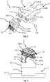
- the figure 2 illustrates an exploded view of the adapter 2 according to this first embodiment of the invention.
- the adapter 2 comprises a body 21 which has a complex shape, for example a generally rectangular shape having chamfered angles. It is obviously understood that any other shape of the body can be proposed to solve the technical problem, without departing from the general principle of the invention.
- the body 21 of the adapter 2 has a lower surface (not visible in the figures) intended to bear against the rotary head 14 of the support 1 and an upper surface 210 intended to cooperate with the rear cover 3 of the electronic payment terminal (illustrated for example in Figures 4A and 4B ).
- the body 21 comprises, substantially in the center of the latter, two through holes 211 passing through the fixing screws 151 which make it possible to fix the adapter 2 to the rotary head 14 of the support 1.
- the adapter 2 comprises a securing clip 22 which makes it possible to control the securing and detaching of the electronic payment terminal on the support 1.
- the clip 22 has a pressure surface, or bearing surface, 221a inclined and extended by a rectilinear surface 221b.
- the rectilinear surface 221b comprises a retaining stud 222 and a fixing base 223.
- the retaining stud 222 protrudes from the rectilinear surface 221b and has a substantially triangular shape.
- the fixing base 223 of the clip 22 has a circular lumen at each of its ends.
- the clip 22 is intended to be secured to the body 21 of the adapter 2.
- the body 21 comprises a housing 215 formed between the lower and upper surfaces 210.
- the housing 215 is configured to receive the fixing base 223 of the clip 22 and has, like the fixing base 223, two circular lights.
- a fixing rod 225 which passes through the lights of the fixing base 223 and those of the housing 215, makes it possible to secure the fixing base 223 of the clip 22 to the body 21, while allowing the clip 22 to pivot relative to the body 21.
- a return element 224 in this example in the form of a spring, is disposed in the housing 215, between the clip 22 for securing and the body 21. Such a return element 224 allows, when a user exerts pressure on the bearing surface 221 of the clip, then releases it, to recall the clip 22 in a so-called nominal or rest position.
- the user When the electronic payment terminal is attached to the adapter 2, the user holds the payment terminal in his hand and comes into contact with the latter against the adapter 2. By pressing on the payment terminal, the user presses in a vertical direction and downwards as indicated by the arrow "P" illustrated on the figure 2 . The return element 224 is then in a compressed position (not shown). When the pressure of the user on the payment terminal, and therefore on the clip 22, is no longer maintained, the return element 224 makes it possible to return the clip 22 to its nominal position (that illustrated on the figures 1 and 2 ).
- This implementation of the various elements forming the adapter 2 according to this embodiment thus allows easy attachment and without tools of the electronic payment terminal on a support 1.
- a simple pressure of the user on the payment terminal when the latter is in contact with the adapter 2 moves the securing clip 22 and makes it possible to position the electronic payment terminal on the body 21 of the adapter 2, the electronic payment terminal being held on the adapter when the user pressure is released.
- the user for example the merchant
- the user wishes to separate the electronic payment terminal from the support 1
- he exerts pressure directly on the clip 22 of the adapter 2 making it possible to free the electronic payment terminal from the body 21 of the adapter 22.
- the adapter 2 further comprises, on an edge of its upper surface 210 (the upper edge of the body 21 as illustrated in the figure 2 ) means 23 for receiving locking means 4 from the electronic payment terminal on the adapter 2.
- the reception means 23 comprise two through holes 231a, 231b located on either side of a notch 232.
- the implementation of the reception means 23 of the locking means 4 of the electronic payment terminal on the adapter 2 will be described in more detail in relation to the other embodiments of the invention.
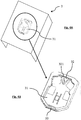
- the rear cover 3 of an electronic payment terminal is adapted to cooperate with the adapter 2. More specifically, the rear cover 3 has a housing 31 of shape corresponding to the shape of the upper surface 210 of the body 21 of the adapter 2.
- the body 21 of the adapter 2 is received in the housing 31 of the rear cover 3, in order to maintain the electronic payment terminal on the adapter (itself fixed on the support 1 for example).
- the corresponding shapes of the body 21 and of the housing 31 make it possible to leave only one degree of freedom in assembly, that allowing the insertion and removal of the body 21 from the adapter 2 in the housing 31 of the rear cover 3 of the electronic payment terminal.
- the housing 31 comprises, in the vicinity of one of its edges (for example the upper edge illustrated in the figure 4B ) a protuberance 32 intended to cooperate, when the adapter 2 is secured to the rear cover 3, with the notch 232 of the adapter 2.
- the protrusion 32 has a blind hole 321 capable of cooperating with the locking means 4 of the electronic payment terminal on the support 1, via the adapter 2 (described in the following embodiments).
- the rear cover 3 further comprises, in the vicinity of another edge of the housing 31 (the lower edge on the figure 4B ), a groove 33 intended to cooperate with the holding stud 222 of the securing clip 22, thus allowing the electronic payment terminal to be held on the adapter 2.
- the adapter 2 After having definitively fixed the adapter 2 on the fixing foot 1 (by means of the fixing screws 151 for example), it suffices to clip the electronic payment terminal onto the adapter 2.
- This operation does not require any additional action on the part of the user since when the terminal is brought into contact against the adapter 2 by the user, the groove 33 of the rear cover 3 guides the holding stud 222 of the clip 22 and compresses the return element 224.
- the adapter 2 can be inserted into the housing 31 of the rear cover 3 and held in the latter by the interaction between the holding stud 222 and the groove 33.
- the attachment of the payment terminal to the adapter 2 may require user pressure on the pressure surface 221a of the clip 2 in order to move the return element 224 into its compressed position, thus allowing the insertion of the body 21 into the housing 31 of the rear cover 3.
- the separation of the electronic payment terminal is also done by a simple pressure P of the user on the pressure surface of the clip 22 to compress the return element 224 and allow the removal of the adapter 2 from the housing 31 of the rear cover 3.
- connection and separation of the electronic payment terminal on the support are simple and quick. In addition, these operations do not require any tool, whether conventional or specific.
- locking means 4 of the electronic payment terminal on the support 1 via the adapter 2 in the form of an intermediate locking element 41.
- the intermediate locking element 41 is in the form of a Kensington® type lock (registered trademark). This type of lock 41 is well known for securing electronic devices such as computers, for example.
- the Kensington® lock 41 has been adapted to be fixed directly (and not via a cable) to the adapter 2, by means of two fixing screws 43 which cooperate respectively with the through holes 231a and 231b of the 'adapter 2.
- a locking pin 42 of the intermediate element 41 projects relative to the upper surface of the intermediate element 41 (as illustrated in the figure 3 ) and is thus located in the notch 232 provided in the body 21 of the adapter.
- the locking pin 42 is thus able to cooperate with the blind hole 321 of the rear cover 3 of the electronic payment terminal in order to lock the latter on the adapter 2 and thus secure the attachment of the electronic payment terminal.
- the locking and unlocking of the intermediate element 41 is done, conventionally and in a known manner, by means of a specific tool such as a wrench.
- the intermediate locking element 41 acts in addition to the clip 22 for securing the electronic payment terminal to the support 1.
- the intermediate locking element 41 provides an additional level of security, optional , compared to the use of the clip 22 alone.
- locking means 4 in the form of a locking screw.
- Such a locking screw is intended to secure the attachment of the electronic payment terminal to the support 1.
- an intermediate piece is mounted on the body 21 of the adapter 2 and is held on the latter by two retaining screws cooperating with the through holes 231a and 231b of the adapter 2.
- the intermediate piece includes a threaded hole which is intended to receive the locking screw. More specifically, the head of the locking screw comes into contact against the lower surface of the intermediate piece and the threaded rod of the locking screw extends through the tapped hole until it cooperates with the blind hole 321 of the rear cover. 3 of the electronic payment terminal in order to lock and thus secure the attachment of the electronic payment terminal to the adapter 2, and therefore to the support 1.
- the locking screw acts in addition to the clip 22 for securing the electronic payment terminal to the support 1.
- this locking screw makes it possible to provide an additional level of security compared to the use of the clip 22 alone.
- the level of security provided by the locking screw provides an intermediate level of securing the attachment of the electronic payment terminal to the support, between the securing clip 22 alone (first securing level) and the combination of the clip 22 and the intermediate element 41 (high level of security because it requires a specific tool).
- the adapter 2 of the invention can also be implemented for wireless electronic payment terminals which are detached from their support (the charging base for example) so that the customer can carry out the transaction in complete confidentiality (insertion of card + PIN code entry).
Landscapes
- Engineering & Computer Science (AREA)
- General Engineering & Computer Science (AREA)
- Physics & Mathematics (AREA)
- General Physics & Mathematics (AREA)
- Mechanical Engineering (AREA)
- Microelectronics & Electronic Packaging (AREA)
- Cash Registers Or Receiving Machines (AREA)
- Details Of Connecting Devices For Male And Female Coupling (AREA)
Description
- Le domaine de l'invention est celui des terminaux électroniques.
- Plus précisément, l'invention concerne des terminaux de paiement électronique destinés à être utilisés sur des supports fixes et la solidarisation de ces terminaux sur ces supports.
- On s'attache plus particulièrement dans la suite de ce document à décrire la problématique existant dans le domaine des terminaux de paiement électronique, à laquelle ont été confrontés les inventeurs de la présente demande de brevet. L'invention ne se limite bien sûr pas à ce domaine particulier d'application, mais présente un intérêt pour tous terminaux électroniques devant faire face à une problématique proche ou similaire.
- On connaît, dans l'état de la technique, des supports tels que des pieds de fixation ou des mâts sur lesquels sont fixés des terminaux de paiement électronique. On retrouve fréquemment ce type de dispositif aux caisses des magasins.
- Les terminaux de paiement électronique sont solidarisés à ces supports par le biais d'un système de vis qui empêchent que le terminal de paiement électronique ne se décroche du support et ne chute.
- Pour des raisons de sécurité, il est préférable que les terminaux de paiement électronique soient désolidarisés de leur support et placés dans un coffre sécurisé lorsqu'ils ne sont pas utilisés, par exemple en dehors des horaires d'ouverture du commerce.
- Ainsi, avant l'ouverture de son commerce, le commerçant doit solidariser chacun des terminaux de paiement électronique de son parc sur leur support respectif à l'aide d'un outil classique (un tournevis). Ensuite, lors de la fermeture de son commerce, le commerçant doit désolidariser les terminaux de paiement électronique de leur support pour les ranger dans le coffre sécurisé.
- Selon cette technique connue, pour effectuer l'opération de paiement, le commerçant saisit le montant de la transaction sur le terminal de paiement électronique puis fait pivoter ce dernier, par rotation du support, vers le client afin qu'il puisse effectuer la transaction en toute confidentialité (insertion de la carte puis saisie du code PIN).
- Un inconvénient de cette technique connue réside dans le fait que les opérations de solidarisation et de désolidarisation des terminaux de paiement électronique sur leur support, qui peuvent être réalisées plusieurs fois par jour, sont chronophages pour la personne qui les réalise.
- En outre, la nécessité d'utiliser un outil, bien que classique, complique l'installation et la désinstallation des terminaux et affecte donc également le temps nécessaire à la réalisation de ces opérations.
- Un exemple d'adaptateur selon le préambule de la revendication 1 est divulgué dans le document
EP2463746 . - En d'autres termes, il n'existe actuellement aucun système simple et rapide permettant de solidariser et désolidariser un terminal de paiement électronique à un support.
- L'invention propose un adaptateur pour la solidarisation réversible d'un terminal de paiement électronique à un support.
- Selon l'invention, l'adaptateur comprend un corps sur lequel est monté un clip de solidarisation réversible du terminal de paiement électronique au support. Selon l'invention, le corps présente en outre au moins deux trous traversants situés de part et d'autre d'une encoche et destinés à coopérer avec des moyens de verrouillage du terminal de paiement électronique sur l'adaptateur. Ainsi, l'adaptateur présente des moyens de réception de moyens de verrouillage permettant, si le commerçant le souhaite, de verrouiller le terminal de paiement électronique sur l'adaptateur afin d'assurer une sécurité supérieure par rapport au simple clipsage du terminal de paiement électronique sur l'adaptateur.
- Ainsi, l'invention repose sur une approche nouvelle et inventive de solidarisation et de désolidarisation d'un terminal de paiement électronique sur un support (par exemple un pied de fixation), par la mise en œuvre d'un adaptateur, entre le support et le terminal de paiement électronique, comprenant un clip de solidarisation du terminal de paiement électronique au support.
- L'utilisation d'un tel adaptateur permet une installation/désinstallation rapide du terminal de paiement électronique sur son support par le commerçant car, contrairement à l'art antérieur, la mise en œuvre du clip de solidarisation permet de s'affranchir de l'utilisation d'un outil pour solidariser/désolidariser le terminal de paiement électronique au/du support.
- En effet, selon les techniques connues, les terminaux de paiement électronique sont fixés à leur support par le biais d'au moins une vis et il est donc nécessaire d'utiliser un outil (un tournevis) pour solidariser et désolidariser le terminal de paiement électronique du support.
- Le clip de solidarisation de l'invention facilite l'installation et la désinstallation du terminal de paiement électronique sur son support puisqu'une simple pression de l'utilisateur sur le clip permet la solidarisation/désolidarisation du terminal de paiement électronique.
- Selon un aspect particulier de l'invention, le clip est monté pivotant sur le corps de l'adaptateur.
- Selon un autre aspect particulier de l'invention, le clip présente un élément de rappel situé entre le clip et le corps.
- Ainsi, la solidarisation et la désolidarisation du terminal de paiement électronique sur le support s'effectuent par une simple pression de l'utilisateur sur le clip, par exemple via le terminal de paiement électronique. Cette pression doit simplement être supérieure à la force de rappel de l'élément de rappel.
- Selon un aspect particulier de l'invention, l'élément de rappel se présente sous la forme d'un ressort.
- Selon un autre aspect particulier de l'invention, le corps présente au moins un trou de passage de moyens de fixation de l'adaptateur sur le support.
- La mise en œuvre de ce trou permet de fixer l'adaptateur sur tout support. Par exemple, les moyens de fixation se présentent sous la forme de deux vis de fixation qui passent à travers deux trous ménagés dans l'adaptateur et viennent ensuite coopérer avec deux trous taraudés ménagés sur le support. Ces moyens de fixation de l'adaptateur au support ne sont pas accessibles lorsque le terminal de paiement électronique est solidarisé à l'adaptateur, assurant ainsi un niveau de sécurité élevé.
- Selon un aspect particulier de l'invention, les trous traversants sont destinés à coopérer avec des moyens de fixation d'un élément de verrouillage intermédiaire formant les moyens de verrouillage et l'encoche est configurée pour coopérer avec un pion de verrouillage de l'élément de verrouillage intermédiaire.
- Ainsi, des moyens de verrouillage, par exemple un verrou de type Kensington®, peuvent être fixés sur l'adaptateur par le biais des trous traversants. L'encoche ménagée entre les trous traversants permet ainsi le passage d'un pion de verrouillage, par exemple le pion du verrou Kensington®, qui coopère ensuite avec une ouverture adaptée ménagée dans la coque du terminal de paiement électronique.
- L'élément intermédiaire ne peut être déverrouillé que par un outil spécifique, ce qui améliore/augmente la sécurité du terminal de paiement électronique lorsqu'il est solidarisé au support par le biais de l'adaptateur de l'invention. En outre, grâce à l'adaptateur de l'invention, il n'est pas nécessaire de mettre en œuvre de câble de verrouillage additionnel puisque l'élément intermédiaire est directement fixé sur l'adaptateur. La sécurisation du terminal de paiement électronique est donc augmentée de façon relativement simple.
- Selon un aspect particulier de l'invention, l'encoche est configurée pour coopérer avec une vis formant les moyens de verrouillage.
- Ainsi, une variante des moyens de verrouillage consiste à mettre en œuvre une vis de verrouillage. Une telle vis de verrouillage permet également d'améliorer/augmenter la sécurité du terminal de paiement électronique lorsqu'il est solidarisé au support. Toutefois, le niveau de sécurité d'une telle vis de verrouillage est inférieur au niveau de sécurité fourni par l'élément intermédiaire puisque dans ce cas, un outil classique (un tournevis) permet le déverrouillage du terminal de paiement électronique.
- Ainsi, l'adaptateur de l'invention propose à son utilisateur trois niveaux de sécurité, à savoir :
- un premier niveau de sécurisation, dans lequel le terminal de paiement électronique est solidarisé au support uniquement par le clip de solidarisation ;
- un niveau de sécurité intermédiaire, dans lequel le terminal de paiement électronique est solidarisé au support par le clip de solidarisation et sécurisé par une vis de verrouillage ; et
- un niveau de sécurité élevé, dans lequel dans lequel le terminal de paiement électronique est solidarisé au support par le clip de solidarisation et sécurisé par un élément de verrouillage intermédiaire (un verrou de type Kensington, par exemple).
- L'invention propose également un terminal de paiement électronique configuré pour coopérer avec un adaptateur tel que décrit précédemment.
- Selon l'invention, le terminal de paiement électronique comprend un capot arrière présentant un logement adapté pour recevoir l'adaptateur.
- Ainsi, le capot arrière du terminal de paiement électronique présente un logement adapté à la forme du corps de l'adaptateur pour recevoir ce dernier et ne laisser qu'un seul degré de liberté à l'ensemble adaptateur-capot arrière. Le seul degré de liberté autorisé de l'ensemble est celui permettant d'insérer et retirer le terminal de paiement électronique, lorsque le clip de solidarisation le permet.
- Selon un aspect particulier de l'invention, le logement présente une rainure d'insertion et de butée du clip de solidarisation de l'adaptateur.
- Selon cet aspect particulier, la rainure présente dans le logement permet de recevoir et maintenir le clip de solidarisation de façon à supprimer le dernier degré de liberté de l'assemblage adaptateur-capot arrière pour empêcher le retrait du terminal de paiement électronique de l'adaptateur.
- Selon un aspect particulier de l'invention, le capot arrière présente, au voisinage du logement, un trou borgne destiné à coopérer avec les moyens de verrouillage du terminal de paiement électronique sur l'adaptateur.
- Selon cet aspect particulier, le trou borgne ménagé dans le capot arrière du terminal de paiement électronique est apte à coopérer soit avec la vis de verrouillage, ou soit avec le pion de verrouillage de l'élément intermédiaire, qui se présente par exemple sous la forme d'un verrou Kensington®. Il est à noter qu'il n'est pas possible de mettre en œuvre à la fois la vis de verrouillage et l'élément intermédiaire.
- Ainsi, la mise en œuvre de ce trou borgne permet, par le biais des moyens de verrouillage de sécuriser le terminal de paiement électronique.
- D'autres caractéristiques et avantages de l'invention apparaîtront à la lecture de la description suivante, donnée à titre d'exemple indicatif et non limitatif, et des dessins annexés, parmi lesquels :
- la
figure 1 est une vue éclatée des différents éléments, et notamment d'un adaptateur permettant la fixation d'un terminal de paiement électronique à un support, selon un mode de réalisation de l'invention ; - la
figure 2 est une vue éclatée d'un adaptateur selon un mode de réalisation de l'invention ; - la
figure 3 illustre, en perspective, un adaptateur fixé sur un support, selon un mode de réalisation de l'invention ; - la
figure 4A illustre, en perspective, le capot arrière d'un terminal de paiement électronique configuré pour coopérer avec l'adaptateur de lafigure 2 ; - la
figure 4b est une vue de détail du capot arrière d'un terminal de lafigure 4A . - Le principe de l'invention repose sur la mise en œuvre d'un adaptateur comprenant un clip de solidarisation afin de solidariser, de manière réversible et simple, un terminal de paiement électronique à un support (par exemple un pied de support).
- On présente maintenant, en relation avec les
figures 1 et2 , une technique de fixation d'un terminal de paiement électronique à un support, mettant en œuvre un adaptateur selon un premier mode de réalisation de l'invention. - Plus précisément, cette technique de fixation met en œuvre un adaptateur 2 par l'intermédiaire duquel un terminal de paiement électronique peut être solidarisé sur un support 1.
- Optionnellement, des moyens de verrouillage 4 peuvent être prévus en plus de l'adaptateur 2, afin de sécuriser la fixation du terminal de paiement électronique sur le support 1. Ces moyens de verrouillage seront décrits plus en détails dans les modes de réalisation suivants.
- Le support 1, sur lequel le terminal de paiement électronique peut être solidarisé, se présente dans cet exemple sous la forme d'un pied de fixation. Il existe de nombreux exemples de supports pour terminal de paiement électronique, permettant de maintenir le terminal de paiement électronique en position facile d'utilisation, que ce soit pour le commerçant comme pour le client.
- Selon l'exemple illustré en
figures 1 et3 , le support 1 présente une embase 12 destinée à être solidement fixée au mobilier d'un commerce par exemple. Une partie fixe 11 est solidaire, à une première extrémité, de l'embase 12 et est prolongée, à une deuxième extrémité, par une partie pivotante 13 mobile en rotation par rapport à la partie fixe 11 selon un axe vertical. De cette manière, le terminal de paiement électronique fixé à ce support 1 peut prendre plusieurs positions, notamment lors d'une transaction. Ainsi, le terminal de paiement électronique peut être orienté face au commerçant lorsque celui-ci saisit le montant de la transaction par exemple, puis orienté face au client afin que celui-ci insère sa carte de paiement puis saisisse son code PIN par exemple. - La partie pivotante 13 comporte une tête rotative 14 apte à pivoter selon un axe horizontal. Ce pivotement est notamment utile pour orienter le terminal de paiement électronique plus ou moins horizontalement, afin par exemple de faciliter l'accès aux touches pour la saisie du code PIN.
- La tête rotative 14 comprend des moyens de fixation 15 de l'adaptateur 2 sur le support 1. Dans l'exemple illustré sur la
figure 1 , les moyens de fixation 15 se présentent sous la forme de deux vis de fixation 151 qui passent à travers des trous 211 ménagés dans l'adaptateur 2 et qui coopèrent ensuite avec des trous 152 taraudés ménagés dans la tête rotative 14. - La
figure 2 illustre une vue éclatée de l'adaptateur 2 selon ce premier mode de réalisation de l'invention. L'adaptateur 2 comprend un corps 21 qui présente une forme complexe, par exemple une forme générale rectangulaire présentant des angles chanfreinés. On comprend bien évidemment que toute autre forme du corps peut être proposée pour résoudre le problème technique, sans s'éloigner du principe général de l'invention. - Le corps 21 de l'adaptateur 2 présente une surface inférieure (non visible sur les figures) destinée à venir en appui contre la tête rotative 14 du support 1 et une surface supérieure 210 destinée à coopérer avec le capot arrière 3 du terminal de paiement électronique (illustré par exemple en
figures 4A et 4B ). - Le corps 21 comprend, sensiblement au centre de ce dernier, deux trous 211 traversants de passage des vis de fixation 151 qui permettent de fixer l'adaptateur 2 sur la tête rotative 14 du support 1.
- Selon ce mode de réalisation de l'invention, l'adaptateur 2 comprend un clip 22 de solidarisation qui permet de commander la solidarisation et la désolidarisation du terminal de paiement électronique sur le support 1.
- Le clip 22 présente une surface de pression, ou surface d'appui, 221a inclinée et prolongée par une surface rectiligne 221b.
- La surface rectiligne 221b comprend un plot de maintien 222 et une base de fixation 223. Le plot de maintien 222 fait saillie par rapport à la surface rectiligne 221b et présente une forme sensiblement triangulaire. La base de fixation 223 du clip 22 présente une lumière circulaire à chacune de ses extrémités.
- Le clip 22 est destiné à être solidarisé au corps 21 de l'adaptateur 2. Pour ce faire, le corps 21 comprend un logement 215 ménagé entre les surfaces inférieure et supérieure 210. Le logement 215 est configuré pour recevoir la base de fixation 223 du clip 22 et présente, comme la base de fixation 223, deux lumières circulaires.
- Ainsi, une tige de fixation 225, qui passe au travers des lumières de la base de fixation 223 et de celles du logement 215, permet de solidariser la base de fixation 223 du clip 22 au corps 21, tout en permettant au clip 22 de pivoter par rapport au corps 21.
- Un élément de rappel 224, se présentant dans cet exemple sous la forme d'un ressort, est disposé dans le logement 215, entre le clip 22 de solidarisation et le corps 21. Un tel élément de rappel 224 permet, lorsqu'un utilisateur exerce une pression sur la surface d'appui 221 du clip, puis la relâche, de rappeler le clip 22 dans une position dite nominale ou de repos.
- Lors de la solidarisation du terminal de paiement électronique sur l'adaptateur 2, l'utilisateur tient le terminal de paiement dans sa main et vient mettre en contact ce dernier contre l'adaptateur 2. En appuyant sur le terminal de paiement, l'utilisateur réalise une pression qui s'effectue dans une direction verticale et vers le bas comme indiqué par la flèche « P » illustrée sur la
figure 2 . L'élément de rappel 224 se trouve alors dans une position comprimée (non illustrée). Lorsque la pression de l'utilisateur sur le terminal de paiement, et donc sur le clip 22, n'est plus maintenue, l'élément de rappel 224 permet de ramener le clip 22 dans sa position nominale (celle illustrée sur lesfigures 1 et2 ). - Cette mise en œuvre des différents éléments formant l'adaptateur 2 selon ce mode de réalisation permet ainsi une fixation aisée et sans outil du terminal de paiement électronique sur un support 1. En effet, comme indiqué ci-dessus, une simple pression de l'utilisateur sur le terminal de paiement lorsque ce dernier est en contact avec l'adaptateur 2 déplace le clip 22 de solidarisation et permet de positionner le terminal de paiement électronique sur le corps 21 de l'adaptateur 2, le terminal de paiement électronique étant maintenu sur l'adaptateur lorsque la pression de l'utilisateur est relâchée. De la même manière, si l'utilisateur (par exemple le commerçant) souhaite désolidariser le terminal de paiement électronique du support 1, il exerce une pression directement sur le clip 22 de l'adaptateur 2, permettant de libérer le terminal de paiement électronique du corps 21 de l'adaptateur 22.
- L'adaptateur 2 comprend, en outre, sur un bord de sa surface supérieure 210 (le bord supérieur du corps 21 comme illustré sur la
figure 2 ) des moyens de réception 23 de moyens de verrouillage 4 du terminal de paiement électronique sur l'adaptateur 2. - Les moyens de réception 23 comprennent deux trous traversants 231a, 231b situés de part et d'autre d'une encoche 232. La mise en œuvre des moyens de réception 23 des moyens de verrouillage 4 du terminal de paiement électronique sur l'adaptateur 2 sera décrite plus en détail en relation avec les autres modes de réalisation de l'invention.
- Comme illustré sur les
figures 4A et 4B , le capot arrière 3 d'un terminal de paiement électronique est adapté pour coopérer avec l'adaptateur 2. Plus précisément, le capot arrière 3 présente un logement 31 de forme correspondant à la forme de la surface supérieure 210 du corps 21 de l'adaptateur 2. - Ainsi, le corps 21 de l'adaptateur 2 est reçu dans le logement 31 du capot arrière 3, afin de maintenir le terminal de paiement électronique sur l'adaptateur (lui-même fixé sur le support 1 par exemple). Les formes correspondantes du corps 21 et du logement 31 permettent de ne laisser qu'un seul degré de liberté à l'assemblage, celui permettant l'insertion et le retrait du corps 21 de l'adaptateur 2 dans le logement 31 du capot arrière 3 du terminal de paiement électronique.
- Selon ce mode de réalisation, le logement 31 comprend, au voisinage d'un de ses bords (par exemple le bord supérieur illustré sur la
figure 4B ) une protubérance 32 destinée à coopérer, lorsque l'adaptateur 2 est solidarisé au capot arrière 3, avec l'encoche 232 de l'adaptateur 2. - La protubérance 32 présente un trou borgne 321 apte à coopérer avec les moyens de verrouillage 4 du terminal de paiement électronique sur le support 1, via l'adaptateur 2 (décrits dans les modes de réalisation suivants).
- Le capot arrière 3 comprend en outre, au voisinage d'un autre bord du logement 31 (le bord inférieur sur la
figure 4B ), une rainure 33 destinée à coopérer avec le plot de maintien 222 du clip 22 de solidarisation, permettant ainsi au terminal de paiement électronique d'être maintenu sur l'adaptateur 2. - La solidarisation d'un terminal de paiement électronique sur le support 1 est donc très simple.
- En effet, après avoir fixé de façon définitive l'adaptateur 2 sur le pied de fixation 1 (par le biais des vis de fixations 151 par exemple), il suffit de venir clipper le terminal de paiement électronique sur l'adaptateur 2. Cette opération ne nécessite aucune action supplémentaire de la part de l'utilisateur puisque lorsque le terminal est amené en contact contre l'adaptateur 2 par l'utilisateur, la rainure 33 du capot arrière 3 guide le plot de maintien 222 du clip 22 et comprime l'élément de rappel 224. Ainsi, l'adaptateur 2 peut être inséré dans le logement 31 du capot arrière 3 et maintenu dans ce dernier par l'interaction entre le plot de maintien 222 et la rainure 33.
- Dans une variante, la solidarisation du terminal de paiement sur l'adaptateur 2 peut nécessiter une pression de l'utilisateur sur la surface de pression 221a du clip 2 afin de déplacer l'élément de rappel 224 dans sa position comprimée, permettant ainsi l'insertion du corps 21 dans le logement 31 du capot arrière 3.
- La désolidarisation du terminal de paiement électronique se fait également par une simple pression P de l'utilisateur sur la surface de pression du clip 22 pour comprimer l'élément de rappel 224 et permettre le retrait de l'adaptateur 2 du logement 31 du capot arrière 3.
- Ainsi, la solidarisation et la désolidarisation du terminal de paiement électronique sur le support sont simples et rapides. De plus, ces opérations ne nécessitent pas d'outil, qu'il soit classique ou spécifique.
- Dans un deuxième mode de réalisation particulier de l'invention, illustré sur la
figure 3 , il est possible de mettre en œuvre, de façon optionnelle, des moyens de verrouillage 4 (du terminal de paiement électronique sur le support 1 via l'adaptateur 2) se présentant sous la forme d'un élément de verrouillage intermédiaire 41. - Dans l'exemple illustré, l'élément de verrouillage intermédiaire 41 se présente sous la forme d'un verrou de type Kensington® (marque déposée). Ce type de verrou 41 est bien connu pour sécuriser des dispositifs électroniques comme des ordinateurs, par exemple.
- Ici, le verrou 41 Kensington® a été adapté afin d'être fixé directement (et non via un câble) à l'adaptateur 2, par le biais de deux vis de fixation 43 qui coopèrent respectivement avec les trous traversants 231a et 231b de l'adaptateur 2.
- Un pion de verrouillage 42 de l'élément intermédiaire 41 fait saillie par rapport à la surface supérieure de l'élément intermédiaire 41 (comme illustré sur la
figure 3 ) et se situe ainsi dans l'encoche 232 prévue dans le corps 21 de l'adaptateur. - Le pion de verrouillage 42 est ainsi apte à coopérer avec le trou borgne 321 du capot arrière 3 du terminal de paiement électronique afin de verrouiller ce dernier sur l'adaptateur 2 et ainsi sécuriser la fixation du terminal de paiement électronique.
- Le verrouillage et le déverrouillage de l'élément intermédiaire 41 se fait, classiquement et de manière connue, par le biais d'un outil spécifique telle une clé.
- La mise en œuvre d'un tel élément intermédiaire 41 permet de s'affranchir de l'utilisation d'un câble de verrouillage et facilite ainsi la sécurisation de la fixation du terminal de paiement électronique.
- Il convient de noter que l'élément de verrouillage intermédiaire 41 vient agir en complément du clip 22 de solidarisation du terminal de paiement électronique au support 1. Ainsi, l'élément de verrouillage intermédiaire 41 permet d'apporter un niveau de sécurité supplémentaire, optionnel, par rapport à l'utilisation du clip 22 seul.
- Dans un troisième mode de réalisation particulier de l'invention (non illustré), il est possible de mettre en œuvre, de façon optionnelle également, des moyens de verrouillage 4 se présentant sous la forme d'une vis de verrouillage.
- Une telle vis de verrouillage est destinée à venir sécuriser la fixation du terminal de paiement électronique sur le support 1.
- Pour ce faire, une pièce intermédiaire est montée sur le corps 21 de l'adaptateur 2 et est maintenue sur ce dernier par deux vis de maintien coopérant avec les trous traversants 231a et 231b de l'adaptateur 2.
- La pièce intermédiaire comprend un trou taraudé qui est destiné à recevoir la vis de verrouillage. Plus précisément, la tête de la vis de verrouillage vient en contact contre la surface inférieure de la pièce intermédiaire et la tige filetée de la vis de verrouillage s'étend à travers le trou taraudé jusqu'à coopérer avec le trou borgne 321 du capot arrière 3 du terminal de paiement électronique afin de verrouiller et ainsi sécuriser la fixation du terminal de paiement électronique sur l'adaptateur 2, et donc sur le support 1.
- Comme pour l'élément de verrouillage intermédiaire 41, la vis de verrouillage vient agir en complément du clip 22 de solidarisation du terminal de paiement électronique au support 1. Ainsi, cette vis de verrouillage permet d'apporter un niveau de sécurité supplémentaire par rapport à l'utilisation du clip 22 seul.
- Toutefois le verrouillage/déverrouillage du terminal nécessite un tournevis, donc un outil classique. Par conséquent, le niveau de sécurité apporté par la vis de verrouillage offre un niveau intermédiaire de sécurisation de la fixation du terminal de paiement électronique sur le support, entre le clip 22 de solidarisation seul (premier niveau de sécurisation) et la combinaison du clip 22 de solidarisation et l'élément intermédiaire 41 (niveau élevé de sécurisation car nécessitant un outil spécifique).
- L'adaptateur 2 de l'invention peut présenter, selon les différents modes de réalisation décrits ci-dessus, trois niveaux de sécurité, à savoir :
- un premier niveau de sécurité, lorsque le terminal de paiement électronique est solidarisé par le clip 22 seul ;
- un deuxième niveau de sécurité, dit intermédiaire, lorsque le terminal de paiement électronique est solidarisé par le clip 22 et sécurisé par la vis de verrouillage ; et
- un troisième niveau de sécurité, dit élevé, lorsque le terminal de paiement électronique est solidarisé par le clip 22 et sécurisé par l'élément intermédiaire 41.
- L'adaptateur 2 de l'invention peut également être mis en œuvre pour des terminaux de paiement électronique sans fil qui sont désolidarisés de leur support (la base de chargement par exemple) pour que le client puisse effectuer la transaction en toute confidentialité (insertion de la carte + saisie du code PIN).
Claims (10)
- Adaptateur (2) pour la solidarisation réversible d'un terminal de paiement électronique à un support (1), ledit adaptateur (2) comprenant un corps (21) sur lequel est monté un clip (22) de solidarisation réversible dudit terminal de paiement électronique audit support (1), ledit adaptateur (2) étant fixé audit support (1) et la désolidarisation dudit terminal de paiement électronique dudit support (1) étant obtenue par une pression d'un utilisateur sur ledit clip, caractérisé en ce que ledit corps (21) présente en outre au moins deux trous traversants (231a, 231b) situés de part et d'autre d'une encoche (232) et destinés à coopérer avec des moyens de verrouillage (4) dudit terminal de paiement électronique sur ledit adaptateur (2).
- Adaptateur (2) selon la revendication 1, caractérisé en ce que ledit clip (22) est monté pivotant sur ledit corps (21) dudit adaptateur (2).
- Adaptateur (2) selon la revendication 2, caractérisé en ce que ledit clip (22) présente un élément de rappel (224) situé entre ledit clip (22) et ledit corps (21).
- Adaptateur (2) selon la revendication 3, caractérisé en ce que ledit élément de rappel (224) se présente sous la forme d'un ressort.
- Adaptateur (2) selon l'une des revendications 1 à 4, caractérisé en ce que ledit corps (21) présente au moins un trou (211) de passage de moyens de fixation (15) dudit adaptateur (2) sur ledit support (1).
- Adaptateur (2) selon l'une des revendications 1 à 5, caractérisé en ce que lesdits trous traversants (231a, 231b) sont destinés à coopérer avec des moyens de fixation (43) d'un élément de verrouillage intermédiaire (41) formant lesdits moyens de verrouillage (4) et ladite encoche (232) est configurée pour coopérer avec un pion de verrouillage (42) dudit élément de verrouillage intermédiaire (41).
- Adaptateur (2) selon la revendication 5, caractérisé en ce que ladite encoche (232) est configurée pour coopérer avec une vis formant lesdits moyens de verrouillage (4).
- Terminal de paiement électronique configuré pour coopérer avec un adaptateur (2) selon l'une des revendications 1 à 7, caractérisé en ce qu'il comprend un capot arrière (3) présentant un logement (31) adapté pour recevoir ledit adaptateur (2).
- Terminal de paiement électronique selon la revendication 8, caractérisé en ce que ledit logement (31) présente une rainure (33) d'insertion et de butée dudit clip (22) de solidarisation dudit adaptateur (2).
- Terminal de paiement électronique selon la revendication 8 ou 9, caractérisé en ce que ledit capot arrière (3) présente, au voisinage dudit logement (31), un trou borgne (321) destiné à coopérer avec lesdits moyens de verrouillage (4) dudit terminal de paiement électronique sur ledit adaptateur (2).
Applications Claiming Priority (1)
| Application Number | Priority Date | Filing Date | Title |
|---|---|---|---|
| FR1754876A FR3067091B1 (fr) | 2017-06-01 | 2017-06-01 | Adaptateur pour la fixation d'un terminal de paiement electronique sur un support |
Publications (2)
| Publication Number | Publication Date |
|---|---|
| EP3409996A1 EP3409996A1 (fr) | 2018-12-05 |
| EP3409996B1 true EP3409996B1 (fr) | 2020-01-29 |
Family
ID=59381528
Family Applications (1)
| Application Number | Title | Priority Date | Filing Date |
|---|---|---|---|
| EP18174718.9A Active EP3409996B1 (fr) | 2017-06-01 | 2018-05-29 | Adaptateur pour la fixation d'un terminal de paiement electronique sur un support |
Country Status (5)
| Country | Link |
|---|---|
| US (1) | US10332361B2 (fr) |
| EP (1) | EP3409996B1 (fr) |
| CA (1) | CA3006817A1 (fr) |
| ES (1) | ES2787074T3 (fr) |
| FR (1) | FR3067091B1 (fr) |
Family Cites Families (3)
| Publication number | Priority date | Publication date | Assignee | Title |
|---|---|---|---|---|
| NL1012402C2 (nl) * | 1999-06-22 | 2000-12-28 | Vogel S Holding Bv | Bevestigingssysteem alsmede deel geschikt voor een dergelijk bevestigingssysteem. |
| US8988862B2 (en) | 2010-03-09 | 2015-03-24 | Dayton Technologies Limited | Performance display device |
| DE102010054156B4 (de) * | 2010-12-10 | 2013-08-29 | Awek Gmbh | Terminalsystem zum Anbringen eines Endgerätes an einem Ständerwerk und zum elektrischen Koppeln des Endgerätes an ein Netzwerk oder eine Verarbeitungseinheit |
-
2017
- 2017-06-01 FR FR1754876A patent/FR3067091B1/fr not_active Expired - Fee Related
-
2018
- 2018-05-29 ES ES18174718T patent/ES2787074T3/es active Active
- 2018-05-29 EP EP18174718.9A patent/EP3409996B1/fr active Active
- 2018-05-30 CA CA3006817A patent/CA3006817A1/fr active Pending
- 2018-06-01 US US15/995,920 patent/US10332361B2/en active Active
Non-Patent Citations (1)
| Title |
|---|
| None * |
Also Published As
| Publication number | Publication date |
|---|---|
| CA3006817A1 (fr) | 2018-12-01 |
| FR3067091B1 (fr) | 2020-05-08 |
| US10332361B2 (en) | 2019-06-25 |
| ES2787074T3 (es) | 2020-10-14 |
| FR3067091A1 (fr) | 2018-12-07 |
| US20180350200A1 (en) | 2018-12-06 |
| EP3409996A1 (fr) | 2018-12-05 |
Similar Documents
| Publication | Publication Date | Title |
|---|---|---|
| FR2745612A1 (fr) | Systeme de pince de retenue | |
| EP0469503A1 (fr) | Dispositif de logement d'une carte à mémoire | |
| EP0860904A2 (fr) | Connecteur pour le raccordement d'une carte à circuit(s) intégré(s) et boítier équipé d'un tel connecteur | |
| EP3883424B1 (fr) | Embout | |
| CH635706A5 (fr) | Connecteur electrique pour un objet portatif. | |
| CH690800A5 (fr) | Dispositif de fixation amovible d'un bracelet à une boîte de montre. | |
| EP3523786B1 (fr) | Système de conversion d'un terminal de paiement électronique mobile en terminal de paiement électronique fixe | |
| EP1362278A1 (fr) | Dispositif de liaison amovible entre deux elements | |
| EP3016079B1 (fr) | Boitier de terminal équipé d'une trappe amovible à profil curviligne | |
| EP3409996A1 (fr) | Adaptateur pour la fixation d'un terminal de paiement electronique sur un support | |
| FR2757329A1 (fr) | Dispositif de maintien pour l'element de commande d'un appareil telephonique ou un telephone mobile | |
| EP2230412B1 (fr) | Bouton tournant sécurisé | |
| EP1554916B1 (fr) | Dispositif de fixation par verrouillage d un appareil destin e a etre monte dans un rack | |
| FR3065684A1 (fr) | Ensemble de garnissage comprenant une piece deployable | |
| EP2700541B1 (fr) | Mécanisme de fixation rapide | |
| EP0683350A1 (fr) | Dispositif de fixation de caméras sur un trépied | |
| WO2015055910A1 (fr) | Accessoire formant bequille amovible | |
| EP2835125B1 (fr) | Dispositif d'accrochage pour une table d'opération | |
| FR2757810A1 (fr) | Dispositif d'enlevement de facade pour systeme audio monte sur vehicule automobile | |
| EP4321384A1 (fr) | Porte-charge d'un véhicule automobile | |
| FR2928555B1 (fr) | Dispositif de portage de skis | |
| FR3137800A1 (fr) | Prise électrique equipée d’un système d’extraction de prise | |
| FR3068582A1 (fr) | Systeme de fixation securise d’un objet sur un mur | |
| EP2833332A1 (fr) | Dispositif de consigneur acceptant des empreintes de clé différentes | |
| FR2721127A1 (fr) | Serrure à consigne pour chariot de marchandises et son procédé de montage. |
Legal Events
| Date | Code | Title | Description |
|---|---|---|---|
| PUAI | Public reference made under article 153(3) epc to a published international application that has entered the european phase |
Free format text: ORIGINAL CODE: 0009012 |
|
| STAA | Information on the status of an ep patent application or granted ep patent |
Free format text: STATUS: THE APPLICATION HAS BEEN PUBLISHED |
|
| AK | Designated contracting states |
Kind code of ref document: A1 Designated state(s): AL AT BE BG CH CY CZ DE DK EE ES FI FR GB GR HR HU IE IS IT LI LT LU LV MC MK MT NL NO PL PT RO RS SE SI SK SM TR |
|
| AX | Request for extension of the european patent |
Extension state: BA ME |
|
| STAA | Information on the status of an ep patent application or granted ep patent |
Free format text: STATUS: REQUEST FOR EXAMINATION WAS MADE |
|
| 17P | Request for examination filed |
Effective date: 20190603 |
|
| RBV | Designated contracting states (corrected) |
Designated state(s): AL AT BE BG CH CY CZ DE DK EE ES FI FR GB GR HR HU IE IS IT LI LT LU LV MC MK MT NL NO PL PT RO RS SE SI SK SM TR |
|
| RIC1 | Information provided on ipc code assigned before grant |
Ipc: G06Q 20/00 20120101ALI20190619BHEP Ipc: F16M 11/04 20060101AFI20190619BHEP Ipc: F16M 11/10 20060101ALI20190619BHEP Ipc: E05B 73/00 20060101ALI20190619BHEP Ipc: G07F 7/00 20060101ALI20190619BHEP |
|
| GRAP | Despatch of communication of intention to grant a patent |
Free format text: ORIGINAL CODE: EPIDOSNIGR1 |
|
| STAA | Information on the status of an ep patent application or granted ep patent |
Free format text: STATUS: GRANT OF PATENT IS INTENDED |
|
| INTG | Intention to grant announced |
Effective date: 20190731 |
|
| GRAJ | Information related to disapproval of communication of intention to grant by the applicant or resumption of examination proceedings by the epo deleted |
Free format text: ORIGINAL CODE: EPIDOSDIGR1 |
|
| GRAL | Information related to payment of fee for publishing/printing deleted |
Free format text: ORIGINAL CODE: EPIDOSDIGR3 |
|
| STAA | Information on the status of an ep patent application or granted ep patent |
Free format text: STATUS: REQUEST FOR EXAMINATION WAS MADE |
|
| GRAS | Grant fee paid |
Free format text: ORIGINAL CODE: EPIDOSNIGR3 |
|
| GRAR | Information related to intention to grant a patent recorded |
Free format text: ORIGINAL CODE: EPIDOSNIGR71 |
|
| STAA | Information on the status of an ep patent application or granted ep patent |
Free format text: STATUS: GRANT OF PATENT IS INTENDED |
|
| GRAA | (expected) grant |
Free format text: ORIGINAL CODE: 0009210 |
|
| STAA | Information on the status of an ep patent application or granted ep patent |
Free format text: STATUS: THE PATENT HAS BEEN GRANTED |
|
| INTC | Intention to grant announced (deleted) | ||
| INTG | Intention to grant announced |
Effective date: 20191213 |
|
| AK | Designated contracting states |
Kind code of ref document: B1 Designated state(s): AL AT BE BG CH CY CZ DE DK EE ES FI FR GB GR HR HU IE IS IT LI LT LU LV MC MK MT NL NO PL PT RO RS SE SI SK SM TR |
|
| REG | Reference to a national code |
Ref country code: GB Ref legal event code: FG4D Free format text: NOT ENGLISH |
|
| REG | Reference to a national code |
Ref country code: CH Ref legal event code: EP |
|
| REG | Reference to a national code |
Ref country code: AT Ref legal event code: REF Ref document number: 1228748 Country of ref document: AT Kind code of ref document: T Effective date: 20200215 |
|
| REG | Reference to a national code |
Ref country code: IE Ref legal event code: FG4D Free format text: LANGUAGE OF EP DOCUMENT: FRENCH |
|
| REG | Reference to a national code |
Ref country code: DE Ref legal event code: R096 Ref document number: 602018002213 Country of ref document: DE |
|
| REG | Reference to a national code |
Ref country code: NL Ref legal event code: MP Effective date: 20200129 |
|
| PG25 | Lapsed in a contracting state [announced via postgrant information from national office to epo] |
Ref country code: FI Free format text: LAPSE BECAUSE OF FAILURE TO SUBMIT A TRANSLATION OF THE DESCRIPTION OR TO PAY THE FEE WITHIN THE PRESCRIBED TIME-LIMIT Effective date: 20200129 Ref country code: RS Free format text: LAPSE BECAUSE OF FAILURE TO SUBMIT A TRANSLATION OF THE DESCRIPTION OR TO PAY THE FEE WITHIN THE PRESCRIBED TIME-LIMIT Effective date: 20200129 Ref country code: NO Free format text: LAPSE BECAUSE OF FAILURE TO SUBMIT A TRANSLATION OF THE DESCRIPTION OR TO PAY THE FEE WITHIN THE PRESCRIBED TIME-LIMIT Effective date: 20200429 Ref country code: PT Free format text: LAPSE BECAUSE OF FAILURE TO SUBMIT A TRANSLATION OF THE DESCRIPTION OR TO PAY THE FEE WITHIN THE PRESCRIBED TIME-LIMIT Effective date: 20200621 |
|
| REG | Reference to a national code |
Ref country code: LT Ref legal event code: MG4D |
|
| PG25 | Lapsed in a contracting state [announced via postgrant information from national office to epo] |
Ref country code: IS Free format text: LAPSE BECAUSE OF FAILURE TO SUBMIT A TRANSLATION OF THE DESCRIPTION OR TO PAY THE FEE WITHIN THE PRESCRIBED TIME-LIMIT Effective date: 20200529 Ref country code: GR Free format text: LAPSE BECAUSE OF FAILURE TO SUBMIT A TRANSLATION OF THE DESCRIPTION OR TO PAY THE FEE WITHIN THE PRESCRIBED TIME-LIMIT Effective date: 20200430 Ref country code: BG Free format text: LAPSE BECAUSE OF FAILURE TO SUBMIT A TRANSLATION OF THE DESCRIPTION OR TO PAY THE FEE WITHIN THE PRESCRIBED TIME-LIMIT Effective date: 20200429 Ref country code: LV Free format text: LAPSE BECAUSE OF FAILURE TO SUBMIT A TRANSLATION OF THE DESCRIPTION OR TO PAY THE FEE WITHIN THE PRESCRIBED TIME-LIMIT Effective date: 20200129 Ref country code: SE Free format text: LAPSE BECAUSE OF FAILURE TO SUBMIT A TRANSLATION OF THE DESCRIPTION OR TO PAY THE FEE WITHIN THE PRESCRIBED TIME-LIMIT Effective date: 20200129 Ref country code: HR Free format text: LAPSE BECAUSE OF FAILURE TO SUBMIT A TRANSLATION OF THE DESCRIPTION OR TO PAY THE FEE WITHIN THE PRESCRIBED TIME-LIMIT Effective date: 20200129 |
|
| PG25 | Lapsed in a contracting state [announced via postgrant information from national office to epo] |
Ref country code: NL Free format text: LAPSE BECAUSE OF FAILURE TO SUBMIT A TRANSLATION OF THE DESCRIPTION OR TO PAY THE FEE WITHIN THE PRESCRIBED TIME-LIMIT Effective date: 20200129 |
|
| REG | Reference to a national code |
Ref country code: ES Ref legal event code: FG2A Ref document number: 2787074 Country of ref document: ES Kind code of ref document: T3 Effective date: 20201014 |
|
| PG25 | Lapsed in a contracting state [announced via postgrant information from national office to epo] |
Ref country code: DK Free format text: LAPSE BECAUSE OF FAILURE TO SUBMIT A TRANSLATION OF THE DESCRIPTION OR TO PAY THE FEE WITHIN THE PRESCRIBED TIME-LIMIT Effective date: 20200129 Ref country code: SK Free format text: LAPSE BECAUSE OF FAILURE TO SUBMIT A TRANSLATION OF THE DESCRIPTION OR TO PAY THE FEE WITHIN THE PRESCRIBED TIME-LIMIT Effective date: 20200129 Ref country code: SM Free format text: LAPSE BECAUSE OF FAILURE TO SUBMIT A TRANSLATION OF THE DESCRIPTION OR TO PAY THE FEE WITHIN THE PRESCRIBED TIME-LIMIT Effective date: 20200129 Ref country code: LT Free format text: LAPSE BECAUSE OF FAILURE TO SUBMIT A TRANSLATION OF THE DESCRIPTION OR TO PAY THE FEE WITHIN THE PRESCRIBED TIME-LIMIT Effective date: 20200129 Ref country code: EE Free format text: LAPSE BECAUSE OF FAILURE TO SUBMIT A TRANSLATION OF THE DESCRIPTION OR TO PAY THE FEE WITHIN THE PRESCRIBED TIME-LIMIT Effective date: 20200129 Ref country code: RO Free format text: LAPSE BECAUSE OF FAILURE TO SUBMIT A TRANSLATION OF THE DESCRIPTION OR TO PAY THE FEE WITHIN THE PRESCRIBED TIME-LIMIT Effective date: 20200129 Ref country code: CZ Free format text: LAPSE BECAUSE OF FAILURE TO SUBMIT A TRANSLATION OF THE DESCRIPTION OR TO PAY THE FEE WITHIN THE PRESCRIBED TIME-LIMIT Effective date: 20200129 |
|
| REG | Reference to a national code |
Ref country code: DE Ref legal event code: R097 Ref document number: 602018002213 Country of ref document: DE |
|
| REG | Reference to a national code |
Ref country code: AT Ref legal event code: MK05 Ref document number: 1228748 Country of ref document: AT Kind code of ref document: T Effective date: 20200129 |
|
| PLBE | No opposition filed within time limit |
Free format text: ORIGINAL CODE: 0009261 |
|
| STAA | Information on the status of an ep patent application or granted ep patent |
Free format text: STATUS: NO OPPOSITION FILED WITHIN TIME LIMIT |
|
| 26N | No opposition filed |
Effective date: 20201030 |
|
| PG25 | Lapsed in a contracting state [announced via postgrant information from national office to epo] |
Ref country code: IT Free format text: LAPSE BECAUSE OF FAILURE TO SUBMIT A TRANSLATION OF THE DESCRIPTION OR TO PAY THE FEE WITHIN THE PRESCRIBED TIME-LIMIT Effective date: 20200129 Ref country code: AT Free format text: LAPSE BECAUSE OF FAILURE TO SUBMIT A TRANSLATION OF THE DESCRIPTION OR TO PAY THE FEE WITHIN THE PRESCRIBED TIME-LIMIT Effective date: 20200129 Ref country code: MC Free format text: LAPSE BECAUSE OF FAILURE TO SUBMIT A TRANSLATION OF THE DESCRIPTION OR TO PAY THE FEE WITHIN THE PRESCRIBED TIME-LIMIT Effective date: 20200129 |
|
| PG25 | Lapsed in a contracting state [announced via postgrant information from national office to epo] |
Ref country code: SI Free format text: LAPSE BECAUSE OF FAILURE TO SUBMIT A TRANSLATION OF THE DESCRIPTION OR TO PAY THE FEE WITHIN THE PRESCRIBED TIME-LIMIT Effective date: 20200129 Ref country code: PL Free format text: LAPSE BECAUSE OF FAILURE TO SUBMIT A TRANSLATION OF THE DESCRIPTION OR TO PAY THE FEE WITHIN THE PRESCRIBED TIME-LIMIT Effective date: 20200129 |
|
| REG | Reference to a national code |
Ref country code: BE Ref legal event code: MM Effective date: 20200531 |
|
| PG25 | Lapsed in a contracting state [announced via postgrant information from national office to epo] |
Ref country code: LU Free format text: LAPSE BECAUSE OF NON-PAYMENT OF DUE FEES Effective date: 20200529 |
|
| PG25 | Lapsed in a contracting state [announced via postgrant information from national office to epo] |
Ref country code: IE Free format text: LAPSE BECAUSE OF NON-PAYMENT OF DUE FEES Effective date: 20200529 |
|
| PG25 | Lapsed in a contracting state [announced via postgrant information from national office to epo] |
Ref country code: BE Free format text: LAPSE BECAUSE OF NON-PAYMENT OF DUE FEES Effective date: 20200531 |
|
| REG | Reference to a national code |
Ref country code: CH Ref legal event code: PL |
|
| PG25 | Lapsed in a contracting state [announced via postgrant information from national office to epo] |
Ref country code: CH Free format text: LAPSE BECAUSE OF NON-PAYMENT OF DUE FEES Effective date: 20210531 Ref country code: LI Free format text: LAPSE BECAUSE OF NON-PAYMENT OF DUE FEES Effective date: 20210531 |
|
| REG | Reference to a national code |
Ref country code: GB Ref legal event code: 732E Free format text: REGISTERED BETWEEN 20220127 AND 20220202 |
|
| PG25 | Lapsed in a contracting state [announced via postgrant information from national office to epo] |
Ref country code: TR Free format text: LAPSE BECAUSE OF FAILURE TO SUBMIT A TRANSLATION OF THE DESCRIPTION OR TO PAY THE FEE WITHIN THE PRESCRIBED TIME-LIMIT Effective date: 20200129 Ref country code: MT Free format text: LAPSE BECAUSE OF FAILURE TO SUBMIT A TRANSLATION OF THE DESCRIPTION OR TO PAY THE FEE WITHIN THE PRESCRIBED TIME-LIMIT Effective date: 20200129 Ref country code: CY Free format text: LAPSE BECAUSE OF FAILURE TO SUBMIT A TRANSLATION OF THE DESCRIPTION OR TO PAY THE FEE WITHIN THE PRESCRIBED TIME-LIMIT Effective date: 20200129 |
|
| PG25 | Lapsed in a contracting state [announced via postgrant information from national office to epo] |
Ref country code: MK Free format text: LAPSE BECAUSE OF FAILURE TO SUBMIT A TRANSLATION OF THE DESCRIPTION OR TO PAY THE FEE WITHIN THE PRESCRIBED TIME-LIMIT Effective date: 20200129 Ref country code: AL Free format text: LAPSE BECAUSE OF FAILURE TO SUBMIT A TRANSLATION OF THE DESCRIPTION OR TO PAY THE FEE WITHIN THE PRESCRIBED TIME-LIMIT Effective date: 20200129 |
|
| REG | Reference to a national code |
Ref country code: DE Ref legal event code: R081 Ref document number: 602018002213 Country of ref document: DE Owner name: BANKS AND ACQUIRES INTERNATIONAL HOLDING, FR Free format text: FORMER OWNER: INGENICO GROUP, PARIS, FR Ref country code: DE Ref legal event code: R082 Ref document number: 602018002213 Country of ref document: DE Representative=s name: STUMPF PATENTANWAELTE PARTGMBB, DE Ref country code: DE Ref legal event code: R081 Ref document number: 602018002213 Country of ref document: DE Owner name: BANKS AND ACQUIRERS INTERNATIONAL HOLDING, FR Free format text: FORMER OWNER: INGENICO GROUP, PARIS, FR |
|
| REG | Reference to a national code |
Ref country code: DE Ref legal event code: R081 Ref document number: 602018002213 Country of ref document: DE Owner name: BANKS AND ACQUIRERS INTERNATIONAL HOLDING, FR Free format text: FORMER OWNER: BANKS AND ACQUIRES INTERNATIONAL HOLDING, SURESNES, FR |
|
| PGFP | Annual fee paid to national office [announced via postgrant information from national office to epo] |
Ref country code: DE Payment date: 20250521 Year of fee payment: 8 |
|
| PGFP | Annual fee paid to national office [announced via postgrant information from national office to epo] |
Ref country code: FR Payment date: 20250530 Year of fee payment: 8 |
|
| REG | Reference to a national code |
Ref country code: ES Ref legal event code: PC2A Owner name: BANKS AND ACQUIRERS INTERNATIONAL HOLDING Effective date: 20250930 |
|
| PGFP | Annual fee paid to national office [announced via postgrant information from national office to epo] |
Ref country code: ES Payment date: 20250630 Year of fee payment: 8 |
|
| P01 | Opt-out of the competence of the unified patent court (upc) registered |
Free format text: CASE NUMBER: UPC_APP_0000328_3409996/2026 Effective date: 20260106 |
|
| PGFP | Annual fee paid to national office [announced via postgrant information from national office to epo] |
Ref country code: GB Payment date: 20260330 Year of fee payment: 9 |